(issue 4) page - arai india · morth / cmvr / tap-115/116 ... positioned in the fuel tank as in...
TRANSCRIPT
MoRTH / CMVR / TAP-115/116 (Issue 4) Page 200
CHAPTER 2 : TYPE-IV TEST (The Determination of Evaporative Emissions from Vehicles with Spark-Ignition Engines) 1 INTRODUCTION:
This chapter describes a method for the determination of the loss of hydrocarbons by evaporation from the fuel systems of vehicles with spark ignition engines.
This is applicable for the passenger cars manufactured from 1.4.1996.
While preparing this standard considerable assistance has been taken from:
a) 91/441/EEC Air pollution by emission from motor vehicles.
2 DESCRIPTION OF TEST:
The evaporative emission test (Figure 1) consists of four phases: - test preparation, - tank breathing loss determination, - Modified Indian Driving cycle (Part I and Part II) - hot soak loss determination.
Mass emissions of hydrocarbons from the tank breathing loss and the hot soak loss phases are summed to provide an overall result for the test.
4 VEHICLE AND FUEL: 3.1 Vehicle 3.1.1 The vehicle must be in good mechanical condition and have been run in and
driven at least 3000 km or less as per manufacturer's choice before the test. The evaporative emission control system must be connected and functioning correctly over this period and the carbon canister subjected to normal use, neither undergoing abnormal purging nor abnormal loading.
3.2 Fuel 3.2.1 The tests shall be conducted with the reference fuel as specified in the applicable
gazette notification. However, at the manufacturer’s request the tests may be carried out with the commercial fuel.
4 TEST EQUIPMENT 4.1 Chassis dynamometer
MoRTH / CMVR / TAP-115/116 (Issue 4) Page 201
The chassis dynamometer must meet the requirements of Part-III.
4.2 Evaporative emission measurement enclosure.
The evaporative emission measurement enclosure must be a gastight rectangular measuring chamber able to contain the vehicle under test. The vehicle must be accessible from all sides and the enclosure when sealed must be gas tight in accordance with Appendix-I. The inner surface of the enclosure must be impermeable to hydrocarbons. At least one of the surfaces must incorporate a flexible impermeable material to allow the equilibration of pressure changes resulting from small changes in temperature. Wall design must be such as to promote good dissipation of heat. The temperature of the wall must not drop below 293 K (20°C) at any point during testing.
4.1 Analytical systems 4.3.1 Hydrocarbon analyser 4.3.1.1 The atmosphere within the chamber is monitored using a hydrocarbon detector of
the flame ionisation detector (FID) type. Sample gas must be drawn from the midpoint of one side wall or roof of the chamber and any bypass flow must be returned to the enclosure, preferably to a point immediately downstream of the mixing fan.
4.3.1.2 The hydrocarbon analyser must have a response time to 90% of final reading of
less than 1.5 seconds. Its stability shall be better than 2% of full scale at zero and at 80 ± 20% of full scale over a 15-minute period for all operational ranges.
4.3.1.3 The repeatability of the analyser expressed as one standard deviation shall be
better than 1% of full scale deflection at zero and at 80 ± 20% of full scale on all ranges used.
4.3.1.4 The operational ranges of the analyser must be chosen to give best resolution over
the measurement, calibration and leak checking procedures. 4.3.2 Hydrocarbon analyser data recording system: 4.3.2.1 The hydrocarbon analyser must be fitted with a device to record electrical signal
output either by strip chart recorder or other data-processing system at a frequency of at least once per minute. The recording system must have operating characteristics atleast equivalent to the signal being recorded and must provide a permanent record of results. The record shall show a positive indication of the beginning and end of the fuel tank heating and hot soak periods together with the time elapsed between start and completion of each test
4.4 Fuel tank heating
MoRTH / CMVR / TAP-115/116 (Issue 4) Page 202
4.4.1 The fuel in the vehicle tank(s) must be heated by a controllable source of heat, for example a heating pad of 2000 W capacity is suitable. The heating system must apply heat evenly to the tank walls beneath the level of the fuel so as not to cause local overheating of the fuel. Heat must not be applied to the vapour in the tank above the fuel.
4.4.2 The tank heating device must make it possible to evenly heat the fuel in the tank
by 14 K from 289K ( 16 °C) within 60 minutes, with the temperature sensor position as in section 5.1.1. The heating system must be capable of controlling the fuel temperature to ± 1.5 K of the required temperature during the tank heating process.
4.5 Temperature recording 4.5.1 The temperature in the chamber is recorded at two points by temperature sensors
which are connected so as to show a mean value. The measuring points are extended approximately 0.1m into the enclosure from the vertical centre line of each side wall at a height of 0.9 ± 0.2m.
4.5.2 The temperatures of the fuel tank(s) shall be recorded by means of the sensor
positioned in the fuel tank as in section 5.1.1. 4.5.3 Temperatures must, throughout the evaporative emission measurements, be
recorded or entered in to a data processing system at a frequency of at least once per minute.
4.5.4 The accuracy of the temperature recording system must be within ± 1.0 K and the
temperature must be capable of being resolved to 0.4 K.
4.5.5 The recording or data processing system must be capable of resolving time to ± 15 seconds.
4.6 Fans 4.6.1 By the use of one or more fans or blowers with the SHED door(s) open it must be
possible to reduce the hydrocarbons concentration in the chamber to the ambient hydrocarbon level.
4.6.2 The chamber must have one or more fans or blowers of likely capacity 0.1 to 0.5
m3 /s with which to thoroughly mix the atmosphere in the enclosure. It must be possible to attain an even temperature and hydrocarbon concentration in the chamber during measurements. The vehicle in the enclosure must not be subjected to a direct stream of air from the fans or blowers.
4.7 Gases 4.7.1 The following pure gases must be available for calibration and operation:
MoRTH / CMVR / TAP-115/116 (Issue 4) Page 203
- purified synthetic air (purity: < 1 ppm C1 equivalent, ≤ 1 ppm CO, ≤ 400 ppm CO2 , ≤ 0.1 ppm NO) : oxygen content between 18 and 21% by volume. - hydrocarbon analyser fuel gas (40 ± 2% hydrogen, and balance
helium with less than 1 ppm C1 equivalent hydrocarbon, less than 400 ppm CO ). - propane (C3 H8 ), 99.5% minimum purity.
4.7.2 Calibration and span gases shall be available containing mixtures of propane (C3 H8 ) and purified synthetic air. The true concentrations of a calibration gas must be within ± 2% of the stated figures. The accuracy of the diluted gases obtained when using a gas divider must be to within ± 2% of the true value. The concentrations specified in Chapter-3 may also be obtained by the use of a gas divider using synthetic air as the diluent gas.
4.8 Additional equipment 4.8.1 The absolute humidity in the test area must be measurable to within ± 5%.
4.8.2 The pressure within the test area must measurable to within ± 0.1 kPa.
5 TEST PROCEDURE 8.2 Test preparation 5.1.1 The vehicle is mechanically prepared before the test as follows:
- The exhaust system of the vehicle must not exhibit any leaks, - The vehicle may be steam cleaned before the test, - The fuel tank of the vehicle must be equipped with a temperature sensor to
enable the temperature to be measured at the midpoint of the fuel in the fuel tank when filled to 40% of its capacity.
- Additional fittings, adapters of devices must be fitted to allow a complete
draining of the fuel tank. 5.1.2 The vehicle is taken into the test area where the ambient temperature is between
293 and 303 K (20°and 30°C).
5.1.3 The canister of the vehicle is purged for 30 minutes by driving the car at 60 km/h at the dynamometer setting prescribed in Chapter-3 of Part-III or by passing air (at room temperature and humidity) through the canister at a flow rate which is identical to the actual air flow through the canister when operating the car at 60 km/h. The canister is subsequently loaded with two diurnal emissions tests.
MoRTH / CMVR / TAP-115/116 (Issue 4) Page 204
5.1.4 The fuel tank(s) of the vehicle is (are) emptied using the fuel tank drain(s) provided. This must be done so as not to abnormally purge nor abnormally load the evaporative control devices fitted to the vehicle. Removal of the fuel cap(s) will normally be sufficient to achieve this.
5.1.5 The fuel tank(s) is(are) refilled with the specified test fuel at a temperature of
between 283 and 287 K (10° and 14°C) to 40% ± 2% of its/their normal fuel capacity. The vehicle's fuel cap(s) must not be replaced at this point.
5.1.6 In the case of vehicles fitted with more than one fuel tank, all the tanks must be
heated in the same way, as described below. The temperatures of the tanks must be identical to within ± 1.5K.
5.1.7 The fuel may be initially heated to the starting temperature of 289 K (16°C) ± 1 K.
As soon as the fuel reaches a temperature of 287 K (14°C), the fuel tank(s) must be sealed. When the temperature of the fuel tank reaches 289 K (16°C) ± 1K a linear heat build of 14 ± 0.5 K over a period of 60 ± 2 minutes begins. The temperature of the fuel during the heating shall conform to the function below to within ± 1.5 K: TF = T0 + 0.2333 * t where: Tf = required temperature (K) T0 = initial temperature of tank (K) t = time from start of the tank heat build in minutes. The elapsed time of the heat build and temperature rise is recorded.
5.1.8 After a period of not more than one hour, the operations of fuel draining and
filling begin according to 5.1.4, 5.1.5, and 5.1.7.
5.1.9 Within two hours of the end of the first tank heating period the second fuel tank heating operation begins as specified in and must be completed with the recording of the temperature rise and elapsed time of the heat build.
5.1.10 Within one hour of the end of the second tank heat build the vehicle is placed on a
chassis dynamometer and is driven through one Part One and two Part Two Driving cycles on chassis dynamometer. Exhaust emissions are not sampled during this operation.
5.1.11 Within five minutes of completing the preconditioning operation specified in
5.1.11 the engine bonnet must be completely closed and the vehicle driven off the chassis dynamometer and parked in the soak area. The vehicle is parked for a
MoRTH / CMVR / TAP-115/116 (Issue 4) Page 205
minimum of 10 hours and a maximum of 36 hours. The engine oil and coolant temperatures must have reached the temperature of the area of within ± 2 K at the end of the period.
5.2 Tank breathing evaporative emission test 5.2.1 The operation of 5.2.4 may begin not less than nine hours not more than 35 hours
after the preconditioning driving cycle. 5.2.2 The measuring chamber shall be purged for several minutes immediately before
the test until a stable background is obtainable. The chamber mixing fan(s) must be switched on at this time also.
5.2.3 The hydrocarbon analyser must be zeroed and spanned immediately before the
test.
5.2.4 The fuel tank(s) must be emptied as in 5.1.4 and refilled with test fuel at a temperature of between 283 and 287 K (10° and 14°C) to 40 ± 2% of the tank's normal volumetric capacity.
5.2.5 The fuel cap(s) of the vehicle must not be fitted at this point.
In the case of vehicles fitted with more than one fuel tank, all the tanks shall be heated in the same way,as described below. The temperatures of the tanks must be identical to within ± 1.5 K.
5.2.6 The test vehicle shall be brought into the test enclosure with the engine switched off and the windows and luggage compartment open. The fuel tank sensors and the fuel tank heating device, if necessary, shall be connected. Immediately begin recording the fuel temperature and the air temperature within the enclosure. The purging fan if still operating is switched off at this time.
5.2.7 The fuel may be artificially heated to the starting temperature of 289 K (16°C) ± 1
K.
5.2.8 As soon as the fuel temperature reaches 287 K (14°C) the fuel tank(s) must be sealed and the chamber sealed so that it is gas-tight.
5.2.9 As soon as the fuel reaches a temperature of 289K (16°C) ± 1 K.
- the hydrocarbon concentration, barometric pressure and the temperature are measured to give the initial readings C HCi , Pi and Ti , for the tank heat build test.
- a linear heat build of 14 ± 0.5 K over a period of 60 ± 2 minutes shall begin.
The temperature of the fuel during the heating shall conform to the function below to within ± 1.5 K:
Tf = To + 0.2333 * t
MoRTH / CMVR / TAP-115/116 (Issue 4) Page 206
where: Tf = required temperature (K) To = initial temperature of tank (K) t = time from start of the tank heat build in minutes.
5.2.10 The hydrocarbon analyser is zeroed and spanned immediately before the end of
the test.
5.2.11 If the temperature has risen by 14 K ± 0.5 K over the 60 ± 2 minutes period of the test the final hydrocarbon concentration in the enclosure is measured (CHCf ). The time or elapsed time Hcf of this together with the final temperature and barometric pressure T f and P f for the hot soak is recorded.
5.2.12 The heat source is turned off and the enclosure door unsealed and opened. The
heating device and temperature sensor are disconnected from the enclosure apparatus. The vehicle doors and luggage compartment may now be closed and the vehicle removed from the enclosure with the engine switched off.
5.2.13 The vehicle is prepared for the subsequent driving cycle and hot soak evaporative
emission test. The cold start test must follow the tank breathing test by a period of not more than one hour.
5.2.14 The testing agency may consider that the design of the vehicle's fuel system may
allow losses to the outside atmosphere at any point. In this case an engineering analysis must be carried out to the satisfaction of the testing agency to establish that vapours are vented to the carbon canister and that these vapours are adequately purged during vehicle operation.
5.3 Driving Cycle: 5.3.1 The determination for evaporative emissions is concluded with the measurement
of hydrocarbon emissions over a 60 minute hot soak period following modified Indian Driving cycle i.e. through one Part One and Part Two Driving cycles on chassis dynamometer. Following the tank breathing losses test, the vehicle is pushed or otherwise manoeuvred onto the chassis dynamometer with the engine switched off. It is then driven through an urban driving cycle as described in Part-III. Exhaust emissions may be sampled during this operation but the results are not used for the purpose of exhaust emission type approval.
5.4 Hot soak evaporative emissions test: 5.4.1 Before the completion of the test run the measuring chamber must be purged for
several minutes until a stable hydrocarbon background is obtained. The enclosure mixing fan(s) must also be turned on at this time.
5.4.2 The hydrocarbon analyser must be zeroed and spanned immediately prior to the
test.
MoRTH / CMVR / TAP-115/116 (Issue 4) Page 207
5.4.3 At the end of the driving cycle the engine bonnet must be completely closed and all connections between the vehicle and the test stand disconnected. The vehicle is then driven to the measuring chamber with a minimum use of the accelerator pedal. The engine must be turned off before any part of the vehicle enters the measuring chamber. The time at which the engine is switched off is recorded on the evaporative emission measurement data recording system and temperature recording begins. The vehicle's windows and luggage compartments must be opened at this stage, if not already opened.
5.4.4 The vehicle must be pushed or otherwise moved into the measuring chamber with
the engine switched off.
5.4.5 The enclosure doors are closed and sealed gas-tight within two minutes of the engine being switched off and within seven minutes of the end of the driving cycle.
5.4.6 The start of a 60 ± 0.5 minute hot soak period begins when the chamber is sealed.
The hydrocarbon concentration, temperature and barometric pressure are measured to give the initial readings CHCi , Pi and Ti for the hot soak test. These figures are used in the evaporative emission calculation, section 6. The ambient SHED temperature T must not be less than 296 K and not more than 304 K during the 60 minute hot soak period.
5.4.7 The hydrocarbon analyser must be zeroed and spanned immediately before the
end of the 60 ± 0.5 minute test period.
5.4.8 At the end of the 60 ± 0.5 minute test period measure the hydrocarbon concentration in the chamber. The temperature and the barometric pressure are also measured. These are the final readings CHCf , Pf and Tf for the hot soak test used for the calculation in section 6. This completes the evaporative emission test procedure.
6 CALCULATION: 6.1 The evaporative emission tests described in section 5 allow the hydrocarbon
emissions from the tank breathing and hot soak phases to be calculated. Evaporative losses from each of these phases is calculated using the initial and final hydrocarbon concentrations, temperatures and pressures in the enclosure, together with the net enclosure volume.
The formula below is used:
MHC = k * V * 10 -4 [ CHCf * Pf / Tf - CHCi * Pi/ Ti]
where: M HC = mass of hydrocarbon emitted over the test phase
(grams).
MoRTH / CMVR / TAP-115/116 (Issue 4) Page 208
C HC = measured hydrocarbon concentration in the enclosure (ppm(volume)C equivalent).
V = net enclosure volume in cubic metres corrected for the volume of the
vehicle, with the windows and the luggage compartment open. If the volume of the vehicle is not determined a volume of 1.42m3 is subtracted.
T = ambient chamber temperature, K.
P = barometric pressure in kPa. H/C = hydrogen to carbon ratio. k = 1.2 (12 + H/C): when: i is the initial reading. f is the final reading.
H/C is taken to be 2.33 for tank breathing losses. H/C is taken to be 2.20 for hot soak losses.
6.2 Overall results of test
The overall hydrocarbon mass emission for the vehicle is taken to be: M total = M TH + M HS M total = overall mass emissions of the vehicle (grams). M TH = hydrocarbon mass emission for the tank heat build (grams). M HS = hydrocarbon mass emission for the hot soak (grams).
MoRTH / CMVR / TAP-115/116 (Issue 4) Page 209
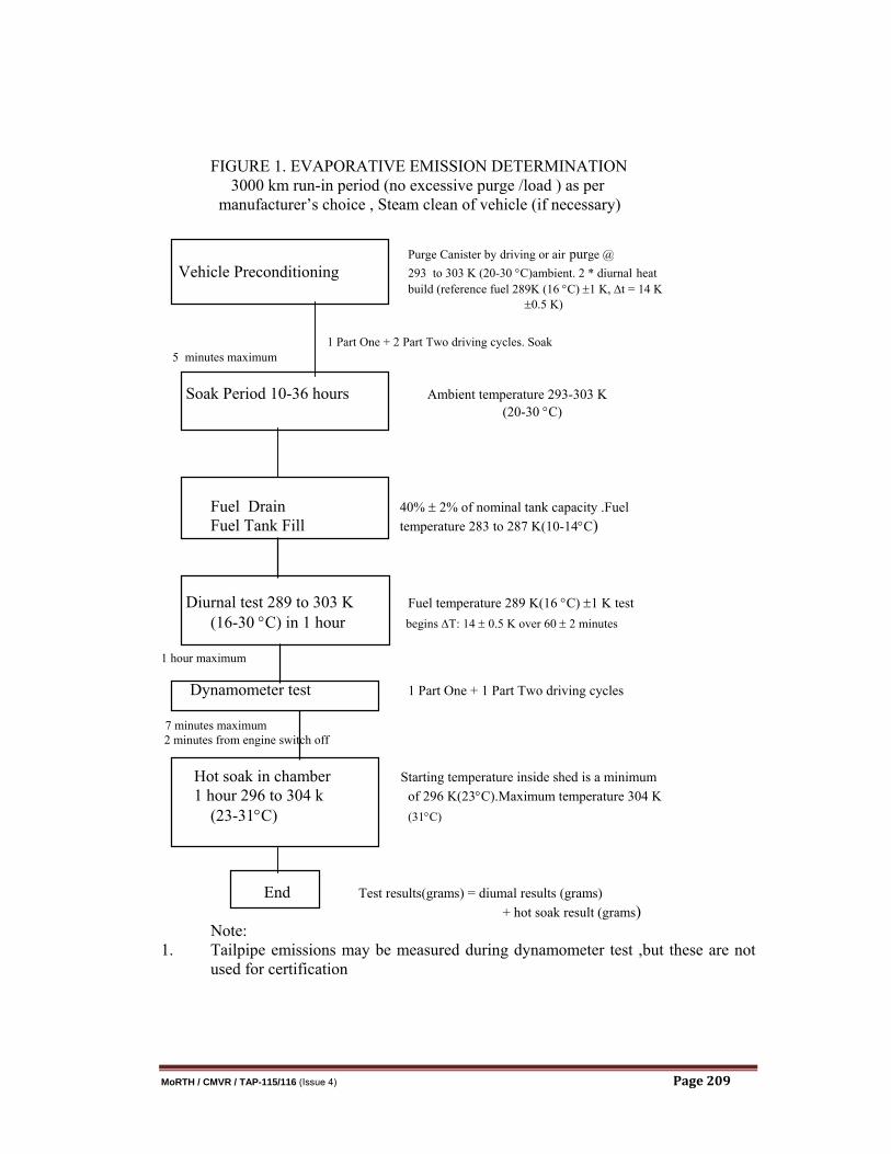
FIGURE 1. EVAPORATIVE EMISSION DETERMINATION 3000 km run-in period (no excessive purge /load ) as per manufacturer’s choice , Steam clean of vehicle (if necessary) Purge Canister by driving or air purge @ Vehicle Preconditioning 293 to 303 K (20-30 °C)ambient. 2 * diurnal heat build (reference fuel 289K (16 °C) ±1 K, ∆t = 14 K
±0.5 K) 1 Part One + 2 Part Two driving cycles. Soak 5 minutes maximum Soak Period 10-36 hours Ambient temperature 293-303 K (20-30 °C) Fuel Drain 40% ± 2% of nominal tank capacity .Fuel Fuel Tank Fill temperature 283 to 287 K(10-14°C) Diurnal test 289 to 303 K Fuel temperature 289 K(16 °C) ±1 K test (16-30 °C) in 1 hour begins ∆T: 14 ± 0.5 K over 60 ± 2 minutes 1 hour maximum Dynamometer test 1 Part One + 1 Part Two driving cycles 7 minutes maximum 2 minutes from engine switch off Hot soak in chamber Starting temperature inside shed is a minimum 1 hour 296 to 304 k of 296 K(23°C).Maximum temperature 304 K (23-31°C) (31°C) End Test results(grams) = diumal results (grams) + hot soak result (grams) Note: 1. Tailpipe emissions may be measured during dynamometer test ,but these are not
used for certification
MoRTH / CMVR / TAP-115/116 (Issue 4) Page 210
7 EXTENSION OF TYPE APPROVAL 7.1 Approval granted to a vehicle type equipped with a control system for evaporative
emissions may be extended under the following conditions : 7.2 The basic principle of fuel/air metering (e.g. single point injection,
carburettor)must be the same.
7.3 The shape of the fuel tank and the material of the fuel tank and liquid fuel hoses must be identical. The worst-case family with regard to the cross-section and approximate hose length must be tested. Whether non-identical vapour liquid separators are acceptable is decided by the test agency responsible for the type approval tests. The fuel tank volume must be within a range of ± 10 %. The setting of the tank relief valve must be identical.
7.4 The method of storage of the fuel vapour must be identical, i.e. trap form and
volume, storage medium, air cleaner(if used for evaporative emission control), etc.
7.5 The carburettor bowl fuel volume must be within a 10 millilitre range. 7.6 The method of purging of the stored vapour must be identical(e.g. air flow, start
point or purge volume over driving cycle). 7.7 The method of sealing and venting of the fuel metering system must be
identical.
7.8 Further notes :
(i) different engine sizes are allowed; (ii) different engine powers are allowed; (iii) automatic and manual gear boxes, two and four wheel transmissions are
allowed; (iv) different body styles are allowed; (v) different wheel and tyre sizes are allowed;
8.0 CONFORMITY OF PRODUCTION: 8.1 For routine end of production-line testing, the holder of the approval may
demonstrate compliance by sampling vehicles which shall meet the following requirements.
8.2 Test for leakage: 8.2.1 Vents to the atmosphere from the emission control system shall be isolated. 8.2.2 A pressure of 370 ± 10 mm of H2O must be applied to the fuel system.
MoRTH / CMVR / TAP-115/116 (Issue 4) Page 211
8.2.3 The pressure must be allowed to stabilize prior to isolating the fuel system from the pressure source.
8.2.4 Following isolation of the fuel system, the pressure must not drop by more than 50
mm of H2O in five minutes. 8.3 Test for Venting: 8.3.1 Vents to the atmosphere from the emission control must be isolated. 8.3.2 A pressure of 370 ± 10 mm of H2O must be applied to the fuel system. 8.3.3 The pressure must be allowed to stabilize prior to isolating the fuel system from
the present source. 8.3.4 The venting outlets from the emission control systems to the atmosphere must be
reinstated to the production condition. 8.3.5 The pressure of the fuel system must drop to below 100 mm of H2O in not less
than 30 seconds but within two minutes. 8.3.6 At the request of the manufacture the functional capacity for venting can be
demonstrated by equivalent alternative procedure. The specific procedure should be demonstrated by the manufacturer to the technical service during the type approval procedure.
8.4 Purge Test: 8.4.1 Equipment capable of detecting an airflow rate of 1.0 litres in one minutes must
be attached to the purge inlet and a pressure vessel of sufficient size to have negligible effect on the purge system must be connected via a switching valve to the purge inlet, or alternatively.
8.4.2 The manufacturer may use a flow meter of his own choice, if acceptable to the competent authority. 8.4.3 The vehicle must be operated in such a manner that any design features of the
purge system that could restrict purge operation is detected and the circumstances noted.
8.4.4 Whilst the engine is operating within the bounds note in 8.4.3 the air flow must be
determined by either. 8.4.4.1 The device indicated in 8.4.1 being switched in. A pressure drop from
atmosphere to a level indicating that a volume of 1.0 litres of air has flowed into the evaporative emission control system within one minute must be observed: or
8.4.4.2 If an alternative flow measuring device is used, a reading of no less than 1.0 litre per minute must be detectable.
MoRTH / CMVR / TAP-115/116 (Issue 4) Page 212
8.4.4.3 At the request of the manufacturer an alternate purge test procedure can be used, if the procedure has been presented to and has been accepted by the technical service during type approval procedure.
8.5 If the requirements of 8.2, 8.3 & 8.4 are not met, the manufacturers must ensure that all necessary steps are taken to re-establish the Conformity of Production as rapidly as possible but in no case exceeding two months by conducting a test on a randomly selected vehicle as per Part VII Chapter 2.