issaquah highlands grand ridge plaza
TRANSCRIPT

ISSAQUAH HIGHLANDS GRAND RIDGE PLAZA
BLOCK 2 – BUILDING 2
SPECIFICATIONS
PRELIMINARY FOR CONSTRUCTION
ARCHITECTS Fuller/Sears Architects
1411 Fourth Avenue, Suite 1306 Seattle, Washington 98101
(206) 682-6170
Contact: Scott Hougham
* 11/19/12 *

FULLER/SEARS ARCHITECTS Grand Ridge Plaza Block2 Building #2
11.19.2012 TABLE OF CONTENTS 00010 - 1 of 4
SECTION 00010
TABLE OF CONTENTS DIVISION I GENERAL REQUIREMENTS Section 01010 Summary of Work 01031 Alteration Project Procedures 01045 Cutting and Patching 01090 Definitions and Standards 01300 Submittals 01352 General LEED Requirements 01400 Quality Control 01450 Structural Testing, Inspection, and Quality Assurance 01500 Construction Facilities 01524 Construction Waste Management 01600 Material and Equipment 01630 Substitutions 01700 Contract Closeout 01740 Warranties 018119 Construction IAQ 019113 Commissioning DIVISION 2 SITE WORK
Refer to Civil Drawings and Geotech Report for additional information. Section 02110 Site Clearing 02200 Earthwork
02205 Aggregate Materials 02500 Site Utilities
02700 Sewerage and Drainage 02710 Foundation Drainage System 02740 Water System
02831 Chain – Link – Fence 02945 Landscape Screen
DIVISION 3 CONCRETE Refer to Structural Drawings for additional information. Section 03100 Concrete Formwork 03200 Concrete Reinforcement 03300 Cast-In-Place Concrete

FULLER/SEARS ARCHITECTS Grand Ridge Plaza Block2 Building #2
11.19.2012 TABLE OF CONTENTS 00010 - 2 of 4
03310 Concrete Work 03345 Concrete Finish 03370 Concrete Curing DIVISION 4 MASONRY Refer to Structural Drawings for additional information. Section 04100 Mortar 04210 Brick Veneer 04220 Concrete Unit Masonry DIVISION 5 METALS Refer to Structural Drawings for additional information. Section 05060 Welding 05120 Structural Steel 05121 Architecturally-Exposed Structural Steel (AESS) 05210 Steel Joist Framing 05310 Steel decking 05400 Cold Form Metal Framing 05500 Metal Fabrications 05515 Metal Ladder 05521 Pipe Railing DIVISION 6 WOOD AND PLASTICS Refer to Structural Drawings for additional information. Section 06105 Miscellaneous Rough Carpentry 06109 Gypsum Sheathing DIVISION 7 THERMAL AND MOISTURE PROTECTION Section 07110 Vapor Barrier 07175 Water Repellents
07270 Air Barriers (WRB-1) 07272 Fluid Applied Air & Water Resistive Barrier (WRB-4) 07460 Hardi Panel Plank
07531 Single-Ply Membrane Roofing-TPO 07600 Flashing and Sheet Metal 07650 Self Adhered Membrane (Wall Opening) WRB-2 07651 Self Adhered Membrane (Parapet) WRB-3 07720 Roof Access Door/Hatch 07900 Joint Sealers

FULLER/SEARS ARCHITECTS Grand Ridge Plaza Block2 Building #2
11.19.2012 TABLE OF CONTENTS 00010 - 3 of 4
DIVISION 8 DOORS AND WINDOWS Section 08100 Metal Doors and Frames 08700 Hardware DIVISION 9 FINISHES Section 09900 Painting Section 09510 Acoustical Ceiling DIVISION 10 SPECIALTIES Section 10440 Signage DIVISION 11 EQUIPMENT - Not Included DIVISION 12 FURNISHINGS - Not Included DIVISION 13 SPECIAL CONSTRUCTION - Not Included DIVISION 14 CONVEYING SYSTEMS - Not Included DIVISION 21 FIRE SUPPRESSION Section 210500 Basic Materials and Methods 211000 Fire Protection DIVISION 22 PLUMBING Section 220500 Basic Materials and Methods 220501 Plumbing 220700 Plumbing Insulation 221123 Plumbing Equipment 222113 Plumbing Piping 224000 Plumbing Fixture DIVISION 22 HEATING VENTILATING AND AIR CONDITIONING Section 230500 Basic Materials and Methods 230593 Testing, Adjustment and Balancing 230700 HVAC Insulation

FULLER/SEARS ARCHITECTS Grand Ridge Plaza Block2 Building #2
11.19.2012 TABLE OF CONTENTS 00010 - 4 of 4
230902 Variable Frequency Drive 233113 Air Distribution 233413 Fans and Vents 237413 Packaged HVAC Units 238239 Heat Transfer DIVISION 26 ELECTRICAL Section 260001 Electrical Design Requirements for LEED v3 Projects 260519 Low-Voltage Electrical Power Conductors and Cables 260526 Grounding and Bonding for Electrical System 260533 Raceway and Bonding for Electrical System 260543 Underground Ducts and Raceways for Electrical System 260553 Identification for Electrical System 262413 Switchboards 262416 Panel boards 262713 Electricity Metering 262726 Wiring Devices 262816 Enclosed Switches and Circuit Breakers DIVISION 27 COMMUNICATIONS Section 271100 Communications Equipment Room Fittings DIVISION 28 ELECTRONIC SAFETY AND SECURITY Section 283111 Digital, Addressable Fire-Alarm System

DIVISION 1

FULLER/SEARS ARCHITECTS Grand Ridge Plaza Block2 Building #2
11.19.2012 SUMMARY OF WORK 01010 – 1 of 5
SECTION 01010
SUMMARY OF WORK PART 1 - GENERAL 1.01 SUMMARY A. Summary of Work: Project consists of construction of Grand Ridge Plaza Blok 2
Building #2 as indicated in Contract Documents. 1. Items noted "NIC" (Not In Contract) will be furnished and installed by Owner or
under separate contract. B. Division 1 - General Requirements: Provisions of General Conditions related to Project
administration and work-related requirements of the Contract, are expanded in Division 1 - General Requirements.
1. General Conditions, Supplementary Conditions and Division 1 - General
Requirements contain information necessary for completion of every part of Project.
2. Where items of Work are done under subcontracts, each item shall be subject to
these conditions. C. Special Definitions: 1. Approved: The terms approved, directed, selected, required, ordered, designated,
accepted, acceptable and satisfactory shall require written action by Architect. 2. Equal, or Approved Equal: The terms equal or approved equal shall require
requests for substitutions for products or manufacturers not specified. a. Requests for substitutions shall be in accordance with requirements of
Section 01630 - Substitutions. 3. Furnish: The term furnish means supply and deliver to Project, unless otherwise
defined in greater detail. 4. Install: The term install is used to describe operations at Project, from inspecting
and unloading, to completion in place, ready for intended use. 5. Provide: The term provide means furnish and install, complete and ready for
intended use, unless otherwise defined in greater detail.

FULLER/SEARS ARCHITECTS Grand Ridge Plaza Block2 Building #2
11.19.2012 SUMMARY OF WORK 01010 – 2 of 5
D. Intent: Drawings and Specifications are intended to provide the basis for proper completion of Work suitable for intended use by Owner.
1. Anything not expressly set forth but which is reasonably implied or necessary for
proper performance of the Project shall be included. 2. In case of an inconsistency within Contract Documents not clarified by addendum,
contractor to provide better quality or greater quantity of Work in accordance with Architect's interpretation. If contractor fails to ask for architect's interpretation contractor will be totally responsible for correcting the condition at no cost.
3. Dimensions: Verify all dimensions indicated on drawings with field dimensions
and conditions before starting work. Resolve all dimensional conflicts and identify to Architect prior to shop drawing review, fabrications and ordering of materials. If Contractor fails to follow these guidelines, the Contractor will be solely responsible for correcting the condition at no cost. Do not scale Drawings.
E. Writing Style: Specifications are written in the imperative mode; except where
specifically intended otherwise, the subject of all imperative statements is the Contractor.
1. Example: "Provide tile" means "Contractor shall provide tile." 1.02 REQUIREMENTS INCLUDED A. This section includes administrative provisions. 1. Work sequence. 2. Contractor use of premises. 3. Coordination. 4. Field engineering. 5. Regulatory requirements and reference standards. 6. Project meetings. 7. Project schedule 1.03 WORK SEQUENCE A. Sequence: Coordinate construction schedule and operations with Architect. 1. Do not remove or alter structural components without prior written approval.

FULLER/SEARS ARCHITECTS Grand Ridge Plaza Block2 Building #2
11.19.2012 SUMMARY OF WORK 01010 – 3 of 5
B. Permits: Apply for, obtain, and pay for permits required to perform Work except for the
building permit which shall be obtained and paid for by the Owner as provided in Article 3.7 of the General Conditions; submit copies to Owner.
C. Existing Conditions: Notify Owner and Architect of existing conditions differing from
those indicated on Drawings in a timely manner. 1.04 CONTRACTOR USE OF PREMISES A. Configurations to areas within contract limits indicated. Portions of the site beyond
areas in which construction operations are indicated are not to be disturbed. B. Coordinate use of premises and access to site under direction of Architect. 1.05 COORDINATION A. Coordinate work to assure efficient and orderly sequence of installation of construction
elements. 1. Make provisions for accommodating items installed by Owner or under separate
contracts. B. Verify characteristics of interrelated operating equipment are compatible; coordinate
work having interdependent responsibilities for installing, connection to, and placing such equipment in service.
C. Coordinate space requirements and installation of mechanical and electrical work which
are indicated diagrammatically on Drawings. 1. Follow routing shown for pipes, ducts, and conduits as closely as possible; make
runs parallel with lines of building and provide complete shop drawing for Architects approval. If contractor fails to do so, contractor will be totally responsible for correcting the condition at no cost.
2. Utilize spaces efficiently to maximize accessibility for other installations, for
maintenance, and for repairs. D. Conceal pipes, ducts, and wiring in finished areas unless otherwise indicated; coordinate
locations of fixtures and outlets with finish elements. 1.06 FIELD ENGINEERING A. Provide field engineering services; establish grades, lines, and levels by use of
recognized engineering survey practices. The Owner will provide layout of property corners, baselines and benchmarks as defined in Article 2 of the General Conditions.
FULLER/SEARS ARCHITECTS Grand Ridge Plaza Block2 Building #2
11.19.2012 SUMMARY OF WORK 01010 – 4 of 5
1. Lay out Work and verify locations during construction. 2. Provide final site survey. B. Locate and protect control and reference points. 1.07 REGULATORY REQUIREMENTS AND REFERENCE STANDARDS A. Regulatory Requirements: 1. Architect has contacted governing authorities and reviewed design requirements
of local, state and federal agencies for applicability to Project. 2. Contractor shall be responsible for contacting governing authorities directly for
necessary information and decisions bearing upon performance of Work. a. Comply with applicable codes and regulations of authorities having
jurisdiction. b. Access: Comply with requirements of both Washington State and Ameri-
cans with Disabilities Act Accessibility Guidelines. B. Reference Standards: 1. For Products specified by association or trade standards, comply with
requirements of referenced standard, except when more rigid requirements are specified or are required by applicable codes.
2. Applicable date of each standard is that in effect as of date on proposal or date on
Contract where no proposal is available, except when a specific date is specified. 1.08 PROJECT TEAM DIRECTORY Owner: Regency Centers 5335 Meadows Rd. Suite 295 Lake Oswego, OR 97035 (503) 603 4729 Contact: Tom Bauwens Architect: Fuller/Sears Architects 1411 4th Avenue, Suite 1306 Seattle, WA 98101 (206) 682-6170

FULLER/SEARS ARCHITECTS Grand Ridge Plaza Block2 Building #2
11.19.2012 SUMMARY OF WORK 01010 – 5 of 5
Contractor: TBD Civil Engineers: MKA 1301 5th Ave #3200 Seattle, WA 98101 (206) 292-1200 Structural: MKA 1301 5th Ave #3200 Seattle, WA 98101 (206) 215 8420 Mechanical Consultant: GLUMAC 1325 4th Ave Suite 1515 Seattle, WA 98101 (206) 262 1010 Electrical Consultant: GLUMAC 1325 4th Ave Suite 1515 Seattle, WA 98101 (206) 262 1010 Landscape: Hewitt 101 Stewart St. Suite 200 Seattle, WA 98101 (206) 624 8154
END OF SECTION

FULLER/SEARS ARCHITECTS Grand Ridge Plaza Block2 Building #2
11.19.2012 ALTERATION PROJECT PROCEDURE 01031 – 1 of 1
SECTION 01031
ALTERATION PROJECT PROCEDURES PART 1 - GENERAL 1.01 SUMMARY A. Owner shall furnish the shell free of all debris, equipment and material as directed by
lease agreement and or demolition plan provided by the Architect. All utilities and services shall be available and located per design documents prior to commencement of work.
END OF SECTION

FULLER/SEARS ARCHITECTS Grand Ridge Plaza Block2 Building #2
11.19.2012 CUTTING AND PATCHING 01045 – 1 of 4
SECTION 01045
CUTTING AND PATCHING PART 1 - GENERAL 1.01 REQUIREMENTS INCLUDED A. Contractor shall be responsible for cutting, fitting and patching required to complete
Work, as provided in Article 3.14 of the General Conditions, and to: 1. Make its parts fit together properly. 2. Uncover work to provide for installation of ill-timed work. 3. Remove and replace defective work. 4. Remove and replace work not conforming to Contract Documents. 5. Remove samples of installed work as required for testing. 6. Provide routine penetrations of non-structural surfaces for installation of piping
and electrical conduit. 1.02 RELATED REQUIREMENTS A. Section 01500: Construction facilities and temporary controls. 1.03 SUBMITTALS A. Submit the following in accordance with Section 01300. B. Submit a written request to Architect well in advance of executing cutting or alteration
which affects: 1. Work of Owner or separate contractor. 2. Structural value or integrity of any element of Project. 3. Integrity of weather-exposed or moisture-resistant elements. 4. Efficiency, operational life, maintenance or safety of operational elements. 5. Visual qualities of sight-exposed elements. C. Request shall include: 1. Identification of Project and description of affected work.

FULLER/SEARS ARCHITECTS Grand Ridge Plaza Block2 Building #2
11.19.2012 CUTTING AND PATCHING 01045 – 2 of 4
2. Necessity for cutting or alteration. 3. Effect on work of Owner or separate contractor, on structural integrity, or
weatherproof integrity of Project. 4. Alternatives to cutting and patching. 5. Cost proposal, when applicable. 6. Written permission of separate contractor whose work will be affected. 7. Description of proposed work including: a. Scope of cutting, patching, alteration, or excavation. b. Products proposed to be used. c. Extent of refinishing to be included. D. Should conditions of Work or schedule indicate a change of products from original
installation, Contractor shall submit request for substitution as specified in Section 01630 - Substitutions.
E. Submit written notice to Architect designating date and time work will be uncovered. 1.04 QUALITY ASSURANCE . A. Requirements for Structural Work: Do not cut and patch structural elements in a
manner that would reduce their load-carrying capacity or load-deflection ratio. B. Operational and Safety Limitations: Do not cut and patch operating elements or safety
related components in a manner that would result in reducing their capacity to perform as intended, or result in increased maintenance, or decreased operational life or safety.
C. Visual Requirements: Do not cut and patch construction exposed on the exterior or in
occupied spaces, in a manner that would, in the Architect's opinion, reduce the building's aesthetic qualities, or result in visual evidence of cutting and patching. Remove and replace Work cut and patched in a visually unsatisfactory manner.
PART 2 - PRODUCTS 2.01 MATERIALS A. Comply with Specifications and standards for each specific product involved.

FULLER/SEARS ARCHITECTS Grand Ridge Plaza Block2 Building #2
11.19.2012 CUTTING AND PATCHING 01045 – 3 of 4
B. Where Specifications and standards have not been provided, provide materials and fabrication consistent with quality of Project and intended for commercial construction.
C. Provide new materials for cutting and patching unless otherwise indicated. PART 3 - EXECUTION 3.01 INSPECTION A. Inspect existing conditions of Project, including elements subject to damage or to
movement during cutting and patching. B. After uncovering work, inspect conditions affecting installation of products, or
performance of work. C. Report unsatisfactory or questionable conditions to Architect in writing; do not proceed
with work until Architect has provided further instructions. 3.02 PREPARATION A. Provide adequate temporary support as necessary to assure structural value or integrity
of affected portion of Work. B. Protect other portions of Project from damage. 3.03 PERFORMANCE A. Execute cutting by methods which provide proper surfaces to receive installation of
repairs and finishes. 1. Execute excavating and backfilling by methods which will prevent settlement and
which will prevent damage to other work. B. Employ same installer or fabricator to perform cutting and patching work as employed
for new construction for: 1. Weather-exposed or moisture resistant elements. 2. Sight-exposed finished surfaces. C. Execute fitting and adjustment of products to provide a finished installation to comply
with specified products, functions, tolerances and finishes. D. Restore work which has been cut or removed; install new products to provide completed
Work in accordance with requirements of Contract Documents. E. Fit work tight to pipes, sleeves, ducts, conduit and penetrations through surfaces.

FULLER/SEARS ARCHITECTS Grand Ridge Plaza Block2 Building #2
11.19.2012 CUTTING AND PATCHING 01045 – 4 of 4
F. Refinish entire surfaces as necessary to provide even finish to match adjacent finishes: 1. For continuous surfaces, refinish to nearest intersection. 2. For an assembly, refinish entire unit. 3.04 CLEANING Thoroughly clean areas and spaces where cutting and patching is performed or used as
access. Remove completely paint, mortar, oils, putty and items of similar nature. Thoroughly clean piping, conduit and similar features before painting or other finishing is applied. Restore damaged pipe covering to its original condition.
END OF SECTION

FULLER/SEARS ARCHITECTS Grand Ridge Plaza Block2 Building #2
11.19.2012 DEFINATIONS AND STANDARD 01090– 1 of 17
SECTION 01090
DEFINITIONS AND STANDARDS
PART 1 – GENERAL 1.01 RELATED WORK ELSEWHERE Refer to the Technical Sections for the items referenced. 1.02 DEFINITIONS A. General: Basic Contract definitions are included in the General Conditions, see Section
01010. 1.03 SPECIFICATION FORMAT AND CONTENT EXPLANATION A. Specification Format: These Specifications are organized into Divisions and Sections
based on the Construction Specifications Institute's 16-Division format and MASTERFORMAT numbering system.
B. Specification Content: This Specification uses certain conventions in the use of
language and the intended meaning of certain terms, words, and phrases when used in particular situations or circumstances. These conventions are explained as follows:
1. Abbreviated Language: Language used in the Specifications and other Contract
Documents is the abbreviated type. Implied words and meanings will be appropriately interpreted. Singular words will be interpreted as plural and plural words interpreted as singular where applicable and where the full context of the Contract Documents so indicates.
2. Imperative and streamlined language is used generally in the Specifications.
Requirements expressed in the imperative mood are to be performed by the Contractor. At certain locations in the text, for clarity, subjective language is used to describe responsibilities that must be fulfilled indirectly by the Contractor, or by others when so noted.
The words "shall be" shall be included by inference wherever a colon (:) is
used within a sentence or phrase. C. Assignment of Specialists: The Specification requires that certain specific construction
activities shall be performed by specialists who are recognized experts in the operations to be performed. The specialists must be engaged for those activities, and assignments are requirements over which the Contractor has no choice or option. Nevertheless, the ultimate responsibility for fulfilling Contract requirements remains with the Contractor.

FULLER/SEARS ARCHITECTS Grand Ridge Plaza Block2 Building #2
11.19.2012 DEFINATIONS AND STANDARD 01090– 2 of 17
1. This requirement shall not be interpreted to conflict with enforcement of building
codes and similar regulations governing the Work. It is also not intended to interfere with local trade union jurisdictional settlements and similar conventions.
1.04 DRAWING SYMBOLS A. Graphic symbols: Where not otherwise noted, symbols are defined by "Architectural
Graphic Standards," published by John Wiley & Sons, Inc. B. Mechanical/Electrical Drawings: Graphic symbols used on mechanical and electrical
Drawings are generally aligned with symbols recommended by ASHRAE. Where appropriate, they are supplemented by more specific symbols recommended by technical associations including ASME, ASPE, IEEE, and similar organizations. Refer instances of uncertainty to the Architect for clarification before proceeding.
1.05 INDUSTRY STANDARDS A. Applicability of Standards: Except where the Contract Documents include more
stringent requirements, applicable construction industry standards have the same force and effect as if bound or copied directly into the Contract Documents. Such standards are made a part of the Contract Documents by reference. Individual Sections indicate which codes and standards the Contractor must keep available at the Project Site for reference.
B. Publication Dates: Where the date of issue of a referenced standard is not specified,
comply with the standard in effect as of the issue date of Contract Documents. C. Conflicting Requirements: Where compliance with two or more standards is specified,
and they establish different or conflicting requirements for minimum quantities or quality levels, the most stringent requirement will be enforced, unless the Contract Documents indicate otherwise. Refer requirements that are different, but apparently equal, and uncertainties as to which quality level is more stringent to the Architect for a decision before proceeding.
D. Copies of Standards: Each entity engaged in construction on the Project is required to
be familiar with industry standards applicable to that entity's construction activity. Copies of applicable standards are not bound with the Contract Documents.
E. Abbreviations and Names: Trade association names and titles of general standards are
frequently abbreviated. Where such acronyms or abbreviations are used in the recognized name of the trade association, standards generating organization, authority having jurisdiction, or other entity applicable to the context of the text provisions, refer to the "Encyclopedia of Associations," published by Gale Research Co., available in most libraries.

FULLER/SEARS ARCHITECTS Grand Ridge Plaza Block2 Building #2
11.19.2012 DEFINATIONS AND STANDARD 01090– 3 of 17
AA Aluminum Association 900 19th St., NW, Suite 300 Washington, DC 20006 202/862-5100 AABC Associated Air Balance Council 1518 K Street NW, Suite 503 Washington, DC 20005 202/737-0202 AAMA American Architectural Manufacturer's Association 1827 Walden Office Square, Suite 104 Schaumberg, IL 60173 847-303-5664 AAN American Association of Nurserymen 1250 Eye Street NW, Suite 500 Washington, DC 20005 202/789-2900 AASHTO American Association of State Highway & Transportation Officials 444 North Capitol St., Suite 249 Washington, DC 20001 202/624-5800 AATCC American Association of Textile Chemists and Colorists P.O. Box 12215 Research Triangle Park, NC 27709 919/549-8141 ACI American Concrete Institute 38800 Country Club Drive Farmington Hills, MI 48331 248-848-3700 ACPA American Concrete Pipe Association 222 W. LasColinas Blvd., Suite 641 Irving, TX 75039 972-506-7216 ADC Air Diffusion Council 104 S. Michigan Ave., Suite 1500 Chicago, IL 60603 312-201-0101

FULLER/SEARS ARCHITECTS Grand Ridge Plaza Block2 Building #2
11.19.2012 DEFINATIONS AND STANDARD 01090– 4 of 17
AHA American Hardboard Association 1210 West N.W. Highway Palatine, IL 60067 847-934-8800 AI Asphalt Institute Research Park Drive P.O. Box 14052 Lexington, KY 40512 606-288-4960 AIA American Institute of Architects 1735 New York Ave., NW Washington, DC 20006 202/626-7300 AIHA American Industrial Hygiene Association 2700 Prosperity Ave, Suite 250 Fairfax, VA 22031 703-849-8888 AISC American Institute of Steel Construction One East Wacker Drive, Suite 3100 Chicago, IL 60601 312-670-2400 AITC American Institute of Timber Construction 7012 S. Revere Parkway, Suite 140 Englewood, CO 80112 303-792-9559 ALI Associated Laboratories 500 S. St. Palatine, IL 60067 312/358-7400 ALSC American Lumber Standards Committee P.O. Box 210 Germantown, MD 20874 301/972-1700 AMCA Air Movement and Control Association 30 W. University Dr. Arlington Heights, IL 60004 312/394-0150 ANSI American National Standards Institute

FULLER/SEARS ARCHITECTS Grand Ridge Plaza Block2 Building #2
11.19.2012 DEFINATIONS AND STANDARD 01090– 5 of 17
11 West 42nd St. 13th Floor New York, NY 10036 212-642-4900 APA American Plywood Association P.O. Box 11700 Tacoma, WA 98411 206/565-6600 ARI Air Conditioning and Refrigeration Institute 4100 N. Fairfax Drive, Suite 200 Arlington, VA 22203 703-524-8800 ARMA Asphalt Roofing Manufacturers Association 6000 Executive Blvd., Suite 201 Rockville, MD 20852 301/231-9050 ASA Acoustical Society of America 500 Sunnyside Blvd. Woodbury, NY 11797 516/349-7800 ASC Adhesive and Sealant Council 1627 K Street NW, Suite 1000 Washington, DC 20006 ASHRAE American Society of Heating, Refrigeration & Air-Conditioning
Engineers 1791 Tullie Circle, NE Atlanta, GA 30329 404/636-8400 ASME American Society of Mechanical Engineers 345 East 47th St. New York, NY 10017 800-THE-ASME ASPE American Society of Plumbing Engineers 3617 Thousand Oaks Blvd., Suite 210 Westlake, CA 91362 805/495-7120

FULLER/SEARS ARCHITECTS Grand Ridge Plaza Block2 Building #2
11.19.2012 DEFINATIONS AND STANDARD 01090– 6 of 17
ASSE American Society of Sanitary Engineering P.O. Box 40362 Bay Village, OH 44140 216/835-3040 ASTM American Society for Testing and Materials 1916 Race St. Philadelphia, PA 19103 215/299-5400 AWI Architectural Woodwork Institute 1952 Isaac Newton Square West Reston, VA 20190 703-733-0600 AWPA American Wood Preservers' Association P.O. Box 849 Stevensville, MD 21666 301/643-4163 AWPB American Wood Preservers Bureau P.O. Box 5283 Springfield, VA 22150 703/339-6660 AWS American Welding Society P.O. Box 351040 550 Le Jeune Rd, NW Miami, FL 33135 305/443-9353 AWWA American Water Works Association 6666 W. Quincy Ave. Denver, CO 80235 303/794-7711

FULLER/SEARS ARCHITECTS Grand Ridge Plaza Block2 Building #2
11.19.2012 DEFINATIONS AND STANDARD 01090– 7 of 17
BHMA Builder's Hardware Manufacturers Association 60 East 42nd St., Room 511 New York, NY 10165 212/682-8142 BIA Brick Institute of America 11490 Commerce Park Drive, Suite 300 Reston, VA 22091 703/620-0010 BIFMA Business and Institutional Furniture Manufacturers Association 2335 Burton St., SE Grand Rapids, MI 49506 616/243-1681 CAUS Color Association of the United States 315 West 3rd. St, Studio 507 New York, NY 10018 212-947-7774 CAGI Compressed Air and Gas Institute c/o Thomas Associates, Inc. 1230 Keith Building Cleveland, OH 44115 216/241-7333 CDA Copper Development Association Box 1840 Greenwich Office Park 2 Greenwich, CT 06836 212-251-7200 CISPI Cast Iron Soil Pipe Institute 1499 Chain Bridge Rd, Suite 203 McLean, VA 22101 703/827-9177 CRI Carpet and Rug Institute 310 Holiday Ave. Dalton, GA 30720 706-226-9925

FULLER/SEARS ARCHITECTS Grand Ridge Plaza Block2 Building #2
11.19.2012 DEFINATIONS AND STANDARD 01090– 8 of 17
CRSI Concrete Reinforcing Steel Institute 933 Plum Grove Road Schaumburg, IL 60173 847-517-1200 CTI Ceramic Tile Institute of America 12061 Jefferson Blvd. Culver City, CA 90230-6219 310-574-7800 / www.ctioa.org DHI Door and Hardware Institute 14150 Newbrook Dr., Suite 200 Chantilly, WA 20151 703-222-2010 / www.dhi.org DLPA Decorative Laminate Products Association 600 S. Federal St, Suite 400 Chicago, IL 60605 312/922-6222 EIMA Exterior Insulation Manufacturers Association 3000 Corporate Center Drive, Suite 270 Morrow, GA 30260 800-294-3462 / www.eifsfacts.com FGMA Flat Glass Marketing Association 3310 Harrison White Lakes Professional Bldg. Topeka, KS 66611 913/266-7013 FM Factory Mutual Engineering and Research 1151 Boston-Providence Turnpike Norwood, MA 02062 617/762-4300 FTI Facing Tile Institute P.O. Box 8880 Canton, OH 44711 216/488-1211 GA Gypsum Association 810 1st St. NE, Suite 510 Washington, DC 20002 202-289-5440 / www.gypsum.org

FULLER/SEARS ARCHITECTS Grand Ridge Plaza Block2 Building #2
11.19.2012 DEFINATIONS AND STANDARD 01090– 9 of 17
HMA Hardwood Manufacturers Association 400 Penn Center Blvd. Pittsburgh, PA 15235 412-829-0770 / www.hadwod.org IEEE Institute of Electrical and Electronic Engineers 345 E. 47th St. New York, NY 10017 212/705-7900 IGCC Insulating Glass Certification Council P.O. Box 9 Henderson Harbor, NY 13651 800-345-3851 / www.igcc.org ILI Indiana Limestone Institute of America Stone City Bank Bldg., Suite 400 Bedford, IN 47421 812/275-4426 / www.iliai.com LPI Lightning Protection Institute 3335 Arlington Heights Rd., Suite E Arlington Heights, IL 60004 800-488-6864 / www.lightning.org MBMA Metal Building Manufacturers' Association 1300 Sumner Ave. Cleveland, OH 44115 216-241-7333 / www.mbma.com MFMA Maple Flooring Manufacturers' Association 60 Revere Drive, Suite 500 Northbrook, IL 60062 847-480-9138 / www.maplefloor.org MIA Marble Institute of America 30 Eden Alley, Suite 301 Columbus, OH 43215 614-228-6194 / www.marble-institute.com ML/SFA Metal Lath/Steel Framing Association 600 S. Federal St., Suite 400 Chicago, IL 60605 312/922-6222 NAAMM National Association of Architectural Metal Mfrs.
FULLER/SEARS ARCHITECTS Grand Ridge Plaza Block2 Building #2
11.19.2012 DEFINATIONS AND STANDARD 01090– 10 of 17
8 S. Michigan Ave, Suite 1000 Chicago, IL 60603 312-332-0405 / www.naamm.org NBGQA National Building Granite Quarries Association 1220 L. St. NW, Suite 100-167 Washington, DC 20005 800-577-2848 / www.nbgga.com NCMA National Concrete Masonry Association 2302 Horse Pen Rd. Herndon, VA 20171 703-713-1900 / www.ncma.org NEC National Electrical Code (by NFPA) NEII National Elevator Industry, Inc. 1677 Country Rt. 64 Salem, NY 12865 518-854-3100 / www.neii.org NEMA National Electrical Manufacturers Association 660 White Plans Rd., Suite 600 Tarrytown, NY 10591 914-524-8650 / www.nema.org NFPA National Fire Protection Association 1 Batterymarch Park Quincy, MA 02269 800-344-3555 / www.nfpa.org N.F.P.A. National Forest Products Association 1250 Connecticut Ave., NW Washington, DC 20036 202/463-2700 NHLA National Hardwood Lumber Association P.O. Box 34518 Memphis, TN 38184 901/377-1818 / www.natlhardwood.org

FULLER/SEARS ARCHITECTS Grand Ridge Plaza Block2 Building #2
11.19.2012 DEFINATIONS AND STANDARD 01090– 11 of 17
NKCA National Kitchen Cabinet Association P.O. Box 6830 Falls Church, VA 22046 703/237-7580 NOFMA National Oak Flooring Manufacturers Association P.O. Box 3009 Memphis, TN 38173 901/526-5016 / www.nofma.org NPA National Particleboard Association 18928 Premiere Court Gaithersburg, MD 20879 301/670-0604 NPCA National Paint and Coatings Association 1500 Rhode Island Avenue, N.W. Washington, DC 20005 202/462-6272 / www.paint.org NRCA National Roofing Contractors Association O’Hare International Center 10255 W. Higgins, RD., Suite 600 Rosemont, IL 60018 847-299-9070 / www.nrca.net NSF National Sanitation Foundation P.O. Box 1468 3475 Plymouth Rd. Ann Arbor, MI 48106 313/769-8010 NSSEA National School Supply and Equipment Association 8300 Colesville Rd, Suite 250 Silver Spring, MO 20910 301-495-0240 / www.nssea.org NTMA National Terrazzo and Mosaic Association 110 E. Market St., Suite 200A Leesburg, VA 20176 800-323-9736 / www.ntma.com NWMA National Woodwork Manufacturers Association (Now NWWDA)

FULLER/SEARS ARCHITECTS Grand Ridge Plaza Block2 Building #2
11.19.2012 DEFINATIONS AND STANDARD 01090– 12 of 17
NWWDA National Wood Window and Door Association (Formerly NWMA) 1400 E. Touhy Ave., #G54 Des Plaines, IL 60018 847-299-5200 PCA Portland Cement Association 5420 Old Orchard Road Skokie, IL 60077 847-966-6200 PCI Prestressed Concrete Institute 209 W. Jackson Blvd., Suite 500 Chicago, IL 60606 312/786-0300 / www.pci.org PEI Porcelain Enamel Institute 5696 Peachtree Parkway Norcross, GA 30092 707-242-2632 / www.porcelainenamel.com RFCI Resilient Floor Covering Institute 401 E. Jefferson St., Suite 102 Rockville, MD 20850 301/340-8580 / www.rfci.com RIS Redwood Inspection Service 591 Redwood Highway, Suite 3100 Mill Valley, CA 94941 RMA Rubber Manufacturers Association 1400 K Street, NW Washington, DC 20005 800-220-7622 / www.rma.org SDI Steel Deck Institute P.O. Box 9506 Canton, OH 44711 216/493-7886 S.D.I. Steel Door Institute 30200 Detroit Rd. Cleveland, OH 44145-1964 440-899-0010 / www.steeldoor.org

FULLER/SEARS ARCHITECTS Grand Ridge Plaza Block2 Building #2
11.19.2012 DEFINATIONS AND STANDARD 01090– 13 of 17
SGCC Safety Glazing Certification Council P.O. Box Henderson Harbor, NY 13651 315-646-2234 / www.sgcc.org SIGMA Sealed Insulating Glass Manufacturers Association 401 N. Michigan Ave, Suite 2400 Chicago, IL 60611 312/644-6610 / www.sigmaonline.org SJI Steel Joist Institute 3127 10th Ave. N. Myrtle Beach, SC 29577 843-626-1995 / www.steeljoist.org SMACNA Sheet Metal & Air Conditioning Contractors National Association 4201 Lafayette Center Dr. Chantilly, VA 20151 703-803-2980 / www.smacna.org SPIB Southern Pine Inspection Bureau 4709 Scenic Hwy. Pensacola, FL 32504 904/434-2611 SPRI Single Ply Roofing Institute The Breeden Co. 104 Wilmont Rd., Suite 201 Deerfield, IL 60015 312/940-8800 SSPC Steel Structures Painting Council 4400 5th Avenue Pittsburgh, PA 15213 412/268-3327 SWI Steel Window Institute (c/o Thomas Associates, Inc.) 1230 Keith Bldg Cleveland, OH 44115 216/241-7333
FULLER/SEARS ARCHITECTS Grand Ridge Plaza Block2 Building #2
11.19.2012 DEFINATIONS AND STANDARD 01090– 14 of 17
TCA Tile Council of America 100 Clemson Research Blvd. Anderson, SC 29625 864-646-TILE / www.tileusa.com TPI Truss Plate Institute 583 D'Onofrio Drive, Suite 200 Madison, WI 53719 608/833-5900 / www.tpinst.org UL Underwriters Laboratories 333 Pfingsten Rd. Northbrook, IL 60062 312/272-8800 WCLIB West Coast Lumber Inspection Bureau P.O. Box 23145 Portland, OR 97223 503/639-0651 WCMA Wallcovering Manufacturers Association 355 Lexington Ave. New York, NY 10017 212/661-4261 WIC Woodwork Institute of California P.O. Box 11428 Fresno, CA 93773 209/233-9035 WRI Wire Reinforcement Institute 8361-A Greensboro Drive McLean, VA 22102 703/790-9790 WSFI Wood and Synthetic Flooring Institute 4415 West Harrison Street, Suite 242 C Hillside, IL 60162 312/449-2933 WLPDIA Western Lath Plaster Drywall Industries Association (Formerly California Lath & Plaster Association) 25332 Narbonne, Suite 170 Lomita, CA 90717 213/539-6080

FULLER/SEARS ARCHITECTS Grand Ridge Plaza Block2 Building #2
11.19.2012 DEFINATIONS AND STANDARD 01090– 15 of 17
WWPA Western Wood Products Association 522 SW 5th Ave., Yeon Bldg. Portland, OR 97204 503/224-3930 / www.wwpa.org W.W.P.A. Woven Wire Products Association 1641 E. Higgins Lake Dr. Roscommon, MI 48653 517-821-6621 / www.wovenwire.org
F. Federal Government Agencies: Names and titles of federal government standard or Specification producing agencies are frequently abbreviated. The following acronyms or abbreviations referenced in the Contract Documents indicate names of standard or Specification producing agencies of the federal government. Names and addresses are subject to change but are believed to be, but are not assured to be, accurate and up to date as of the date of the Contract Documents.
CE Corps of Engineers (US Dept. of the Army) 441 G St. NW Washington, DC 20314 202-761-1683 CFR Code of Federal Regulations Available from the Government Printing Office North Capitol Street between G and H Streets, NW Washington, DC 20402 202/783-3238 (Material is usually first published in the Federal Register) CPSC Consumer Product Safety Commission 4330 East-West Highway Bethesda, MD 20814 301-504-0580 / www.cpsc.gov CS Commercial Standard (U.S. Dept. of Commerce) Government Printing Office Washington, DC 20402 202/377-2000 DOC Department of Commerce 1401 Constitution Ave NW Washington, DC 20230 202-482-1850 DOT Department of Transportation

FULLER/SEARS ARCHITECTS Grand Ridge Plaza Block2 Building #2
11.19.2012 DEFINATIONS AND STANDARD 01090– 16 of 17
400 Seventh Street, SW Washington, DC 20590 202-783-1876 EPA Environmental Protection Agency 401 M Street, SW Washington, DC 20460 202/382-2090 FAA Federal Aviation Administration (U.S. Dept. of Transportation) 800 Independence Avenue, SW Washington, DC 20590 202/366-4000 FCC Federal Communications Commission 445 12th St. SW Washington, DC 20554 202-418-1000 FHA Federal Housing Administration (U.S. Dept. of Housing and Urban Development) 451 Seventh Street, SW Washington, DC 20201 202/755-6422 FS Federal Specifications (from GSA) Specifications Unit (WFSIS) 7th and D Streets, SW Washington, DC 20406 202/472-2205 or 472-2140 GSA General Services Administration F Street and 18th Street, NW Washington, DC 20405 202-708-5082 MIL Military Standardization Documents (U.S. Dept. of Defense) Naval Publications and Forms Center 5801 Tabor Avenue Philadelphia, PA 19120 NIST National Institute of Standards and Technology

FULLER/SEARS ARCHITECTS Grand Ridge Plaza Block2 Building #2
11.19.2012 DEFINATIONS AND STANDARD 01090– 17 of 17
(U.S. Dept. of Commerce) Administration Bldg. #A1134 Gaithersburg, MD 20899 301/975-2300 OSHA Occupational Safety and Health Administration (U.S. Dept. of Labor) 200 Constitutional Ave. NW Washington, DC 20210 800-321-6742 PS Product Standard of NBS (U.S. Dept. of Commerce) Government Printing Office Washington, DC 20402 202/783-3238 USDA U.S. Department of Agriculture Independence Avenue between 12th & 14th Streets, SW Washington, DC 20250 202/447-8732 USPS U.S. Postal Service 1600 Pennsylvania Ave NW Washington, DC 20500 800-275-8777
PART 2 - PRODUCTS (Not Applicable) PART 3 - PRODUCTS (Not Applicable) END OF SECTION 01090

FULLER/SEARS ARCHITECTS Grand Ridge Plaza Block2 Building #2
11.19.2012 SUBMITTALS 01300 – 1 of 6
SECTION 01300
SUBMITTALS
PART 1 – GENERAL 1.01 REQUIREMENTS INCLUDED A. This section describes general procedural requirements for ongoing submittals as
defined in AIA G810. Submittals include all the items listed in this Section 01300. "Submittal Complete" is intended to mean that a complete submittal has been submitted to architect for review. This section includes the following:
1. Construction progress schedules. 2. Schedule of values. 3. Shop drawings. 4. Product data. 5. Samples. 6. Mock-ups. 7. Manufacturers' certificates. 1.02 RELATED REQUIREMENTS A. Section 01400: Test reports, manufacturer's field reports. B. Section 01600: Manufacturers' instructions. C. Section 01630: Substitution requests. D. Section 01700: Closeout submittals. 1. Project record documents. 2. Operating and maintenance data. E. Section 01740: Warranties.

FULLER/SEARS ARCHITECTS Grand Ridge Plaza Block2 Building #2
11.19.2012 SUBMITTALS 01300 – 2 of 6
1.03 PROCEDURES A. Submittals: Transmit each item (all shop drawings, catalog cuts, brochures, mailable
samples, documents and photographs) under AIA Form G810 or a similar approved form submitted to Architect.
1. Identify Project, Contractor, subcontractor, major supplier. 2. Identify pertinent Drawing sheet and detail number, and Specification section
number as appropriate. 3. Provide space for Contractor and Architect review stamps. 4. Contractor: Review and stamp submittals from subcontractors prior to submitting
to Architect. Failure to do so shall result in the Contractor's responsibility to make corrections at no cost to the Owner even if the submittal was approved.
a. Review submittals and indicate where conflicts occur with Contract
Documents and/or with work of other subcontractors. If not clearly indicated, it is the contractor's responsibility to make correction at no cost to the owner even if the submittal was approved, by the architect.
b. Return submittals which vary significantly from Contract Documents for
correction and re-submittal prior to submitting to Architect. c. Submittals which vary significantly from Contract Documents and which
fail to indicate thorough Contractor review prior to submission to Architect will be returned without review.
d. Cursory review and stamping of subcontractor submittal by Contractor shall
not be acceptable. e. Non-compliance or partial compliance with complete submittal process and
requirements will not be acceptable. Contractor is responsible to make correction at no cost to owner even if the submittal was approved.
f. Clearly identify any variance from the contract documents. Failure to do so
shall result in the Contractor's responsibility to make corrections at no cost to the Owner even if the submittal was approved.
5. Preparation: Prepare a separate submittal form for each product or procedure and
identify by referencing the specification section and paragraph number. 6. Mailing: Send the original in every instance which will be the Contractor's record
and final correspondence for every submittal.

FULLER/SEARS ARCHITECTS Grand Ridge Plaza Block2 Building #2
11.19.2012 SUBMITTALS 01300 – 3 of 6
7. It is the Contractors responsibility to obtain a reviewed copy of submittals so as to not interfere with schedule to meet final completion date required. In the event of rejected submittals, the Contractor is responsible to allow for required time for resubmittals.
8. Substitutions must be submitted per Sections 01630, 01600. 9. Sequentially number the transmittal forms. Resubmittals to have original number
with an alphabetic suffix. 10. Apply Contractor's stamp, signed or initialed certifying that review, verification of
Products required, field dimensions, adjacent construction Work, and coordination of information, is in accordance with the requirements of the Work and Contract Documents.
11. Schedule submittals to expedite the Project, and deliver the required number of
copies to Architect at business address. Coordinate submission of related items. 12. Identify variations from Contract Documents and Product or system limitations
which may be detrimental to successful performance of the completed Work. Approval of a variance does not relieve the Contractor from providing all appurtenances necessary to make the item perform as was intended in the original design.
13. Revise and resubmit submittals as required, identify all changes made since
previous submittal. 14. Distribute copies of reviewed submittals to concerned parties. Instruct parties to
promptly report any inability to comply with provisions. 15. Submit shop and detail drawings in related packages. All equipment or material
details which are interdependent or are related in any way must be submitted indicating the complete installation. Submittals shall not be altered once approved for construction. Clearly mark and date revisions. Major revisions must be resubmitted for approval.
16. Thoroughly review all shop and detail drawings, prior to submittal, to assure
coordination with other parts of the Work. Failure to comply will be cause for rejection. Submittals shall bear the Contractor's approval stamp and initials of the reviewer.
17. Components or materials which require shop drawings and which arrive at the job
site prior to approval of shop drawings shall be considered as not being made for this project and shall be subject to rejection and removal from the premises.

FULLER/SEARS ARCHITECTS Grand Ridge Plaza Block2 Building #2
11.19.2012 SUBMITTALS 01300 – 4 of 6
B. Initial Schedules: Submit a comprehensive submittal schedule, initial progress schedule and schedule of value in duplicate within 15 days after award of Contract.
1. After review by Architect revise and resubmit where required. 2. Submit revised progress schedules with each Application for Payment reflecting
changes since previous submittal, failure to do so shall result in postponing the payment process until the submittal of progress schedule.
C. Comply with progress schedule for submittals related to Work progress. Coordinate
submittal of related items. D. After Architect review of submittal, revise and resubmit as required, identify changes
made since previous submittal. E. Distribute copies of reviewed submittals to concerned persons. Instruct recipients to
promptly report any inability to comply. 1.05 SCHEDULE OF VALUES A. Submit typed schedule on AIA Form G703. Contractor's standard media-driven
printout will be considered on request. B. Format: Table of Contents of this Project Manual, with modifications as approved;
identify each line item with number and title of major Specification sections. C. Include in each line item a directly-proportional amount of Contractor overhead and
profit. D. Revise schedule to list change orders for each Application for Payment. 1.06 SHOP DRAWINGS A. Quality: Prepare shop drawings accurately to scale sufficiently large to indicate all
pertinent features of the products and the method of fabrication, connection, erection, or assembly with respect to the Work.
B. Types of Prints Required: 1. Submit shop drawings or supplemental working drawings in the form of one
transparency (sepia, vellum or mylar) of each sheet, two blue line or black line prints of each sheet. 2. Distribution: The Architect and/or the Architect's Consultant will review the
drawings, mark the transparency with appropriate notations, prepare the prints

FULLER/SEARS ARCHITECTS Grand Ridge Plaza Block2 Building #2
11.19.2012 SUBMITTALS 01300 – 5 of 6
for their use, and return the marked transparency to the Contractor. The Contractor will then, at his own expense, make additional copies from the transparency as required for the work.
C. Structural Fabrication and Erection Drawings: All shop drawings which indicate
structural fabrication or erection details shall bear the seal of a Structural Engineer licensed in the State of Washington.
1.07 PRODUCT DATA/MANUFACTURERS' LITERATURE A. Mark each copy to identify applicable Products, models, options, and other data;
supplement manufacturers' standard data to provide information unique to the Work. B. Include manufacturers' installation instructions only when required by Specifications or
specifically requested by Architect. 1. Maintain copy of manufacturer installation instructions and recommendations in
Contractor's field office for review. C. Submit number of copies which Contractor requires, plus three copies which will be
retained by Architect. 1.08 SAMPLES A. Submit full range of manufacturers' standard colors, textures, and patterns for
Architect's selection. B. Submit samples to illustrate functional characteristics of Product, with integral parts and
attachment devices. The sample submitted shall be the exact or precise article. C. Coordinate submittal of different categories for interfacing work. D. Include identification on each sample, giving full information. E. Submit minimum three samples of each item unless otherwise specified. 1. Architect will retain one sample. 2. Provide on sample to Owner. 3. Maintain one sample at Field Office. F. Sizes: Provide following sizes unless otherwise specified: 1. Flat or Sheet Products: Minimum 6" square, maximum 12" x 12". 2. Linear Products: Minimum 6", maximum 12" long.

FULLER/SEARS ARCHITECTS Grand Ridge Plaza Block2 Building #2
11.19.2012 SUBMITTALS 01300 – 6 of 6
3. Bulk Products: Minimum one pint, maximum one gallon. G. Full size samples may be used in the Work upon approval. 1.09 MOCK-UPS A. Building assemblies and/or Inspection components, shall be provided by the Contractor
for in-place and remote field testing to verify compliance with the Contract Documents as specified within the individual trade sections. Do not provide additional materials until approval is received from the Owner and Architect. Failure to comply with erection of mock-up samples shall be deemed as Contractor agreement to refurnish and correct the condition as per architect instruction.
1.10 MANUFACTURERS' CERTIFICATES A. Submit certificates, in duplicate, in accordance with requirements of Specification
section.
END OF SECTION

FULLER/SEARS ARCHITECTS Grand Ridge Plaza Block2 Building #2
11.19.2012 GENERAL LEED REQUIREMENTS 01352 – 1 of 7
SECTION 01 35 20
LEED REQUIREMENTS
PART 1 – GENERAL 1.1 RELATED DOCUMENTS
A. Drawings and general provisions of the Contract, including General and Supplementary Conditions and other Division 1 Specification Sections, apply to this Section.
1.2 SUMMARY
A. Section includes general requirements and procedures for compliance with certain USGBC LEED prerequisites and credits needed for Project to obtain LEED Silver certification based on LEED-CS, Version 2.0. 1. Other LEED prerequisites and credits needed to obtain LEED certification depend on material
selections and may not be specifically identified as LEED requirements. Compliance with requirements needed to obtain LEED prerequisites and credits may be used as one criterion to evaluate substitution requests and comparable product requests.
2. Additional LEED prerequisites and credits needed to obtain the indicated LEED certification depend on Architect's design and other aspects of Project that are not part of the Work of the Contract.
3. A copy of the LEED Project checklist is attached at the end of this Section for information only.
B. Related Sections: 1. Divisions 1 through 16 Sections for LEED requirements specific to the work of each of these
Sections. Requirements may or may not include reference to LEED. 2. 01 52 40 – Construction Waste Management 3. 01 83 00 – Construction Indoor Air Quality 4. 01 91 93 - Commissioning
1.3 DEFINITIONS
A. LEED-CS v2.0: Leadership in Energy & Environmental Design- Core & Shell Development version 2.0. All references to LEED throughout the Construction Documents shall mean LEED-CS v2.0.
B. Reused Material: Salvaged, refurbished or reused materials, products and furnishings that have been returned to active use in the same or related capacity as their original use.
C. Recycled Content: The percentage by weight of constituents that have been recovered or otherwise
diverted from the solid waste stream, either during the manufacturing process (pre-consumer or post-industrial), or after consumer use (post-consumer).
1. "Post-consumer" material is defined as waste material generated by households or by commercial,
industrial, and institutional facilities in their role as end users of the product, which can no longer be used for its intended purpose.
2. "Pre-consumer" material is defined as material diverted from the waste stream during the manufacturing process. Excluded is reutilization of materials such as rework, regrind, or scrap generated in a process and capable of being reclaimed within the same process that generated it.

FULLER/SEARS ARCHITECTS Grand Ridge Plaza Block2 Building #2
11.19.2012 GENERAL LEED REQUIREMENTS 01352 – 2 of 7
a. Scraps, spills or other waste from the original manufacturing process that are combined with other constituents after a minimal amount of reprocessing for use in the further production of the same product are not recycled materials.
D. Regional Materials: Materials that are harvested (extracted or recovered), processed and manufactured
within a radius of 500 miles from the Project location.
1.4 SUBMITTALS
A. General: Submit additional LEED submittals required by other Specification Sections.
B. LEED submittals are in addition to other submittals. If submitted item is identical to that submitted to comply with other requirements, submit duplicate copies as a separate submittal to verify compliance with indicated LEED requirements.
C. Project Materials Cost Data: Provide the necessary cost data requested on the LEED Materials
Calculator including the total Project materials cost and itemized costs of specific materials being tracked for LEED credits. All material costs exclude labor and equipment and the total materials cost is exclusive of Specialties, Conveying Systems and Mechanical and Electrical components.
D. LEED Action Plans: Provide preliminary submittals within 14 days of date established for the Notice to
Proceed indicating how the following requirements will be met:
1. Credit MR 2.1 and Credit MR 2.2: Waste management plan complying with Division 1 Section 01524 "Construction Waste Management."
2. Credit MR 4.1 and Credit MR 4.2: List of proposed materials with recycled content. Indicate cost,
post-consumer recycled content, and pre-consumer recycled content for each product having recycled content.
3. Credit MR 5.1 and Credit MR 5.2: List of proposed regional materials. Identify each regional
material, including its source, cost, and the fraction by weight that is considered regional.
4. Credit EQ 3: Construction IAQ Management Plan: Construction indoor air quality management plan complying with Division 1 Section “Construction IAQ Management.”
E. LEED Progress Reports: Concurrent with each Application for Payment, submit reports summarizing
progress in construction and purchasing activities related to the following credits: 1. Credit MRc2 – Construction Waste Management: Construction waste reduction progress reports
complying with Division 1 Section “Construction Waste Management.” 2. Credit MRc3 – Materials Reuse: Summary of product data and material costs collected for all
salvaged and refurbished materials that have been purchased or installed.
3. Credit MRc4 – Recycled Content: Summary of product data and material costs collected for all recycled content materials that have been purchased or installed.
4. Credit MRc5 – Regional Materials: Summary of manufacturer’s information and material costs
collected for all regional materials that have been purchased or installed.
5. Credit EQc3 – Construction IAQ Management Plan: Construction indoor air quality management reports complying with Division 1 Section “Construction IAQ Management.”
6. Credit EQc4 – Low-Emitting Materials: Summary of product data collected for all adhesives,
sealants, paints, coatings, and carpeting that are installed inside of the building’s moisture barrier.
F. LEED Documentation Submittals:

FULLER/SEARS ARCHITECTS Grand Ridge Plaza Block2 Building #2
11.19.2012 GENERAL LEED REQUIREMENTS 01352 – 3 of 7
1. Credit SSc4.2 – Alternative Transportation, Bicycle Storage and Changing Rooms: Cut sheets of
installed bicycle securing apparatus. 2. Credit SSc6.2 – Stormwater Design, Quality Control: Cut sheets indicating tested removal rates for
stormwater treatment systems.
3. Credit SSc7.2 – Heat Island Effect, Roof: Cut sheets and product data for roofing materials indicating solar reflectance index (SRI).
4. Credit WEc1 – Water Efficient Landscaping: Cut sheets of irrigation system components and
controls contributing to water savings.
5. Credit WEc3 – Water Use Reduction: Cut sheets for all faucets, showers, toilets and urinals indicating flow rates (gallons/minute) and flush volumes (gallons/flush).
6. Credit EAc5 – Measurement & Verification: Cut sheets for sensors and data collection systems
used to provide metering of building energy and water use and performance.
7. Credit MRc2 – Construction Waste Management:
a. Comply with Division 1 Section “Construction Waste Management and Disposal.”
b. Construction Waste Management Plan.
c. Complete LEED construction waste calculations.
d. Itemized waste hauling certificates/receipts for all waste removed from the Project site and documentation of recycling recovery rate for off-site sorting facilities (if waste is commingled).
8. Credit MRc3 – Materials Reuse:
a. Cut sheet or other documentation from the manufacturer/supplier identifying the material as
reused.
b. Material cost. If the cost of the reused material is lower than a comparable new material, include the cost of the new material along with an explanation of assumptions made regarding material value.
9. Credit MRc4 – Recycled Content:
a. Cut sheet, product literature or letter from manufacturer that clearly indicates the percentage
by weight of post-consumer and pre-consumer (post-industrial) recycled content.
b. Material cost.
10. Credit MRc5 – Regional Materials:
a. Cut sheet, product literature or letter from manufacturer indicating the location of harvest, processing and manufacturer.
b. Material cost.
11. Credit EQc3 – Construction IAQ Management Plan, During Construction:
a. Comply with Division 1 Section “Construction IAQ Management.”

FULLER/SEARS ARCHITECTS Grand Ridge Plaza Block2 Building #2
11.19.2012 GENERAL LEED REQUIREMENTS 01352 – 4 of 7
b. Cut sheets indicating MERV values for filtration media used during construction.
12. Credit EQc4.1 – Low-Emitting Materials, Adhesives and Sealants:
a. Product data and Material Safety Data Sheets (MSDS) for all adhesives and sealants used inside the building’s moisture barrier indicating the Volatile Organic Compound (VOC) content of each product and verifying that each product meets the LEED requirements (Refer to “Low Emitting Materials” paragraph in Part 2). Indicate VOC content in grams/liter (g/l) calculated according to 40 CFR 59, Subpart D (EPA method 24).
b. List of all installed adhesives and sealants including manufacturer, quantity used in gallons
and VOC content.
13. Credit EQc4.2 – Low-Emitting Materials, Paints and Coatings:
a. Product data and Material Safety Data Sheets (MSDS) for all paints and coatings used inside the building’s moisture barrier indicating the VOC content of each product and verifying that each product meets the LEED requirements (Refer to “Low Emitting Materials” paragraph in Part 2). Indicate VOC content in grams/liter (g/l) calculated according to 40 CFR 59, Subpart D (EPA method 24).
b. List of all installed paints including manufacturer, quantity used in gallons and VOC content.
14. Credit EQc4.3 – Low-Emitting Materials, Carpet and Flooring:
a. Cut sheets of letter from manufacturer clearly indicating that all carpet products meet the
CRI Green Label Test Program requirements.
b. All resilient flooring must be certified as compliant with the Floorscore standard. Floorscore tests and certifies hard surface flooring and associated products for compliance with California Section 1350 requirements for individual Volatile Organic Compounds (VOCs) of concern. Certified flooring products meeting the standard will bear the FloorScore seal.
15. Credit EQc4.4 – Low-Emitting Materials, Composite Wood: Cut sheets clearly indicating the bonding agents used for each composite wood and agri-fiber product and assembly used in the project and demonstrating that no added urea-formaldehyde resins are used in these products.
1.5 QUALITY ASSURANCE
A. LEED Coordinator: Engage an experienced LEED-Accredited Professional to coordinate LEED requirements. LEED coordinator may also serve as waste management coordinator.
PART 2 – PRODUCTS 2.1 Credit SSc7.2 – Heat Island Effect, Roof
A. Solar Reflectance Index (SRI) must meet the following:
Roof Type Slope SRI Low-Sloped Roof < 2:12 78 Steep-Sloped Roof > 2:12 29
2.2 Credit WEc3 – Water Use Reduction
A. Plumbing fixtures must not exceed the following rates: 1. Pressure assist water closet (=< 1.28 gpf),

FULLER/SEARS ARCHITECTS Grand Ridge Plaza Block2 Building #2
11.19.2012 GENERAL LEED REQUIREMENTS 01352 – 5 of 7
2. Low-flow urinal (=< 0.5 gpf), 3. Aerators on lavs (=< 0.5 gpm),
2.3 RECYCLED CONTENT OF MATERIALS
A. Credit MR 4.1 and Credit MR 4.2: Provide site and building materials with recycled content such that post-consumer recycled content plus 1/2 of pre-consumer recycled content constitutes a targeting 20% but with a minimum of 10% of cost of materials used for Project. 1. Do not include furniture, plumbing, mechanical and electrical components, and specialty items such
as elevators and equipment in the calculation.
2.4 REGIONAL MATERIALS
A. Credit MR 5.1 and Credit MR 5.2: Provide site and building materials that are regionally extracted, processed and manufactured materials targeting 20% but with a minimum of 10% of cost of materials used for Project.
2.5 LOW-EMITTING MATERIALS
A. EQ Credit 4.1: Adhesives and Sealants
1. Adhesives and sealants used on the interior of the building shall comply with the VOC limits of the South Coast Rule #1168 by the South Coast Air Quality Management District, dated July 1, 2005 and rule amendment date of January 7, 2005 (www.aqmd.gov/rules/reg/reg11/r1168.pdf).
2. VOC limits in grams per liter for adhesives and sealants used on interior of building are as follows:
VOC Limit (g/L) Welding and Installation Indoor Carpet Adhesives 50 Carpet Pad Adhesives 50 Wood Flooring Adhesive 100 Rubber Floor Adhesives 60 Subfloor Adhesives 50 Ceramic Tile Adhesives 65 VCT and Asphalt Tile Adhesives 50 Dry Wall and Panel Adhesives 50 Cove Base Adhesives 50 Multipurpose Construction Adhesives 70 Structural Glazing Adhesives 100 PVC Welding 510 CPVC Welding 490 ABS Welding 325 Plastic Cement Welding 250 Adhesive Primer for Plastic 550 Contact Adhesive 80 Special Purpose Contact Adhesive 250 Substrates Metal to metal 30 Plastic foams 50 Porous material except wood 50 Wood 30 Fiberglass 80

FULLER/SEARS ARCHITECTS Grand Ridge Plaza Block2 Building #2
11.19.2012 GENERAL LEED REQUIREMENTS 01352 – 6 of 7
3. Limits on VOCs in grams per liter for carpet
adhesives shall comply with the VOC limits shown below:
B. EQ Credit 4.2: Paints and Coatings 1. Paints applied on the interior of the building shall comply with Green Seal Product Specific
Environmental Requirements (www.greenseal.org/standard/paints.htm). The Green Seal standard is intended for paints and anti-corrosive paints. Both interior and exterior paints are addressed by the standard, but only limits for interior paints apply to a LEED project. Architectural paints coating and primers applied to interior walls as well as Anti-corrosive paints applied to interior ferrous metal shall not exceed the VOC limits as put forth Green Seal Standard GS-11. Limits on VOCs in grams per liter for paints and anti-corrosive paints are as follows:
Interior Coatings VOC Limit (g/L) Non-flat 150 Flat 50 Anti-Corrosive (Green Seal GS-03) 250
2. Clear wood finishes, floor coatings, stain, sealers and shellacs applied to interior elements shall
comply with the VOC limits set forth in the South coast Air Quality Management District (SCAQMD) rule 1113, Architectural Coatings, dated January, 2004.
VOC Limit (g/L)
Clear Wood Finish Varnish 350 Laquer 550 Floor Coatings 100 Sealers Waterproofing sealers 250 Sanding sealers 275 All other sealers 200 Shellac Clear 730 Pigmented 550 Stains 250
C. Credit EQc4.4 – Low-Emitting Materials, Composite Wood: Cut sheets clearly indicating the bonding agents used for each composite wood and agri-fiber product and assembly used in the project and demonstrating that no added urea-formaldehyde resins are used in these products.
Sealants Architectural 250 Other 420 Sealant Primers Architectural- Nonpourous 250 Architectural- Pourous 775 Other 750
VOC Limit (g/L) Adhesives Total VOCs 50

FULLER/SEARS ARCHITECTS Grand Ridge Plaza Block2 Building #2
11.19.2012 GENERAL LEED REQUIREMENTS 01352 – 7 of 7
PART 3 – EXECUTION 3.1 REFRIGERANT AND CLEAN-AGENT FIRE-EXTINGUISHING-AGENT REMOVAL
A. Prerequisite EA 3: Remove CFC-based refrigerants from existing HVAC&R equipment indicated to remain and replace with refrigerants that are not CFC based. Replace or adjust existing equipment to accommodate new refrigerant as described in Division 15 Sections.
END OF SECTION 01352

FULLER/SEARS ARCHITECTS Grand Ridge Plaza Block2 Building #2
11.19.2012 QUALITY CONTROL 01400– 1 of 4
SECTION 01400
QUALITY CONTROL PART 1 - GENERAL 1.01 REQUIREMENTS INCLUDED A. This section describes general quality control requirements including: 1. Manufacturers' field services. 2. Independent testing laboratory services. 3. Mock-ups. 4. Pre qualification of subcontractors. 1.02 RELATED REQUIREMENTS A. Refer to applicable codes and Specification sections for test requirements. 1.03 QUALITY CONTROL, GENERAL A. Maintain quality control over suppliers, manufacturers, products, services, site
conditions, and workmanship, to produce work of specified quality. Quality control services include inspections and tests and related actions including reports, performed by independent agencies and governing authorities. They do not include Contract review activities performed by the Architect.
Inspection and testing services are required to verify compliance with requirements
specified or indicated. These services do not relieve the Contractor of responsibility for compliance with Contract Document requirements.
1.04 MANUFACTURER'S FIELD SERVICES A. When specified in respective Specification sections or as warranted, require
manufacturer or supplier to have qualified personnel provide on-site observations and recommendations.
1. Observe field conditions, including conditions of surfaces and installation. 2. Observe quality workmanship.

FULLER/SEARS ARCHITECTS Grand Ridge Plaza Block2 Building #2
11.19.2012 QUALITY CONTROL 01400– 2 of 4
3. Provide recommendations to assure acceptable installation and workmanship. 4. Where required, start, test, and adjust equipment as applicable. B. Representative shall submit written report to Architect listing observations and
recommendations. 1.05 TESTING LABORATORY SERVICES. A. The Owner will provide testing laboratory services required by local authorities for
conformance to applicable codes and as specified in various specification sections. B. An independent testing laboratory shall perform inspections, test, and other services
required by various Specification sections. 1. Owner will employ and pay for testing laboratory to provide Project-specific
testing under Specification sections indicated as provided by Owner. a. Owner employment of testing laboratory shall not relieve Contractor of
obligation to perform Work in accordance with requirements of Contract Documents.
b. Laboratory may not release, revoke, alter, or enlarge on requirements of
Contract Documents. 2. Re-testing required because of non-conformance to specified requirements shall
be performed by Owner's testing laboratory. a. Payment for re-testing shall be charged to Contractor by deducting
inspection and testing charges from Contract amount. b. Contractor Option: Pay Owner's testing laboratory directly for costs of re-
testing where acceptable to Owner and testing laboratory. 3. Testing shall be limited to Project-specific testing and shall not include general
tests or approvals of materials, equipment or systems. C. Services shall be performed in accordance with requirements of governing authorities
and with specified standards. D. Reports shall be submitted to Architect, owner and appropriate Engineer in duplicate,
giving observations and results of tests, indicating compliance or non-compliance with specified standards and with Contract Documents.

FULLER/SEARS ARCHITECTS Grand Ridge Plaza Block2 Building #2
11.19.2012 QUALITY CONTROL 01400– 3 of 4
1. Where required, testing laboratory shall submit copy of test results directly to enforcing agency.
E. Contractor shall cooperate with testing laboratory personnel; furnish tools, samples of
materials, design mix, equipment, storage and assistance as requested. 1. Notify Architect and testing laboratory sufficiently in advance of expected time
for operations requiring testing services. 1.06 MOCK-UPS A. Erect field samples and mock-ups at Project site in accordance with requirements where
included in Specification section.
PART 2 -PRODUCTS (Not Applicable)
PART 3 –EXECUTION
3.01 REPAIR AND PROTECTION A. General: Upon completion of inspection, testing, sample-taking and similar services,
repair damaged construction and restore substrates and finishes to eliminate deficiencies, including deficiencies in visual qualities of exposed finishes. Comply with Contract Document requirements for "Cutting and Patching."
3.02 REQUIRED INSPECTIONS AND TESTS The following are inspections and tests required of the Inspection and Testing agency. A. Sitework inspections and tests:
1. Compaction and bearing: Test and verify bearing capacity of all load-bearing earth; test compaction of fills for compliance with required densities.
B. Reinforcing Steel: Inspect placement for conformity with approved shop drawings. C. Cast-in-Place Concrete: Make slump tests, at least 3 tests per day during continuous
pours in accordance with requirements for ASTM C143; check and verify batch consistency. Inspect forms and verify sizes and conditions. Furnish continuous inspection during placements. make, cure and test at least 3 test cylinders for each day's pour. Report exact mix tested, minimum size aggregate, location of pour in cylinder in laboratory, slump data, cement brand and type, admixtures used, dates and records of

FULLER/SEARS ARCHITECTS Grand Ridge Plaza Block2 Building #2
11.19.2012 QUALITY CONTROL 01400– 4 of 4
test cylinders, names of inspectors and laboratory personnel and evaluation or analysis of cause in case of failure.
D. Structural Steel Fabrication and Erection (including field welding and high strength
field bolting). E. Metal Deck Installation (including field welding). F. Expansion Bolts and Threaded Expansion Inserts. G. Epoxy Grouted Installations H. Pile Installation and Driven Pile Installation. I. Fire Proofing. J. Shoring. K. Other inspections as required by local, state or federal municipalities.
END OF SECTION

FULLER/SEARS ARCHITECTS Grand Ridge Plaza Block2 Building #2
96212.00 01 45 00 - 1 11/19/12
PART 1 - GENERAL
1.1 RELATED DOCUMENTS
A. The drawings and general provisions of the Contract, including General and Supplementary Conditions and Division 1 Specification Sections, apply to this Section.
1.2 SUMMARY
A. Section Includes: Inspection and testing laboratory services for materials, products, and construction methods as specified hereafter for the work.
B. All special testing and inspections for the Seismic Load Resisting System as described herein.
C. Costs: The costs of the initial services for testing and inspection personnel will be paid by the Owner. If initial tests indicate non-compliance with contract document requirements, any subsequent testing shall be performed by the same personnel and paid for by the contractor. Schedule portions of the work requiring testing and inspections services so as to be continuous and as brief as possible.
D. Code Compliance Inspection and Tests: Inspections and tests not specified herein and required by codes and ordinances, or by plan approval authorities, and made by a legally constituted authority, shall be the responsibility of the contractor, unless otherwise specified.
1.3 REFERENCE STANDARDS
A. General: Comply with the provisions of the latest versions of the publications listed below except as otherwise shown or specified.
B. The Building Code as defined in the Structural Drawings.
C. American Concrete Institute (ACI):
1. ACI 301 Specifications for Structural Concrete
D. American Institute of Steel Construction (AISC):
1. AISC 341 Seismic Provisions for Structural Steel Buildings, dated March 2005, including Supplement No. 1, dated November 2005.
E. American National Standards Institute (ANSI)/American Society for Nondestructive Testing (ASNT):
1. ANSI/ASNT CP-189-1995 2. ANSI/ASNT SNT-TC-1A
FULLER/SEARS ARCHITECTS Grand Ridge Plaza Block2 Building #2
96212.00 01 45 00 - 2 11/19/12
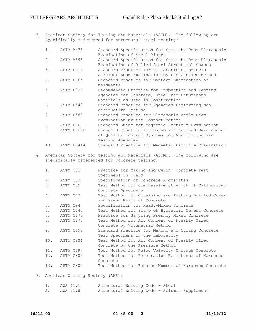
F. American Society for Testing and Materials (ASTM). The following are specifically referenced for structural steel testing:
1. ASTM A435 Standard Specification for Straight-Beam Ultrasonic Examination of Steel Plates
2. ASTM A898 Standard Specification for Straight Beam Ultrasonic Examination of Rolled Steel Structural Shapes
3. ASTM E114 Standard Practice for Ultrasonic Pulse-Echo Straight Beam Examination by the Contact Method
4. ASTM E164 Standard Practice for Contact Examination of Weldments
5. ASTM E329 Recommended Practice for Inspection and Testing Agencies for Concrete, Steel and Bituminous Materials as used in Construction
6. ASTM E543 Standard Practice for Agencies Performing Non-destructive Testing
7. ASTM E587 Standard Practice for Ultrasonic Angle-Beam Examination by the Contact Method
8. ASTM E709 Standard Guide for Magnetic Particle Examination 9. ASTM E1212 Standard Practice for Establishment and Maintenance
of Quality Control Systems for Non-destructive Testing Agencies
10. ASTM E1444 Standard Practice for Magnetic Particle Examination
G. American Society for Testing and Materials (ASTM). The following are specifically referenced for concrete testing:
1. ASTM C31 Practice for Making and Curing Concrete Test Specimens in Field
2. ASTM C33 Specification of Concrete Aggregates 3. ASTM C39 Test Method for Compressive Strength of Cylindrical
Concrete Specimens 4. ASTM C42 Test Method for Obtaining and Testing Drilled Cores
and Sawed Beams of Concrete 5. ASTM C94 Specification for Ready-Mixed Concrete 6. ASTM C143 Test Method for Slump of Hydraulic Cement Concrete 7. ASTM C172 Practice for Sampling Freshly Mixed Concrete 8. ASTM C173 Test Method for Air Content of Freshly Mixed
Concrete by Volumetric Method 9. ASTM C192 Standard Practice for Making and Curing Concrete
Test Specimens in the Laboratory 10. ASTM C231 Test Method for Air Content of Freshly Mixed
Concrete by the Pressure Method 11. ASTM C597 Test Method for Pulse Velocity Through Concrete 12. ASTM C803 Test Method for Penetration Resistance of Hardened
Concrete 13. ASTM C805 Test Method for Rebound Number of Hardened Concrete
H. American Welding Society (AWS):
1. AWS D1.1 Structural Welding Code – Steel 2. AWS D1.8 Structural Welding Code - Seismic Supplement

FULLER/SEARS ARCHITECTS Grand Ridge Plaza Block2 Building #2
96212.00 01 45 00 - 3 11/19/12
1.4 DEFINITIONS
A. Testing Agency refers to the organization or group of organizations responsible for representing the Owner and performing all inspection, testing, and laboratory services as described herein.
B. Seismic Load Resisting System (SLRS) is defined as the assembly of structural elements in the building that resists seismic forces as described in the general structural notes.
C. Demand Critical (DC) welds for the SLRS are identified in the drawings at welded connections as required for quality assurance measures (at welded connections) as specified in AWS D1.8 and AISC 341.
1.5 SUBMITTALS
A. Testing agency shall submit the following:
1. The qualifications of the testing agency management and personnel designated to the project.
2. The testing agency "Written Practice for Quality Assurance." 3. Qualification records for Inspector and NDT technicians designated
for the project. 4. The testing agency NDT procedures, equipment calibration records,
and personnel training records. 5. The testing agency Quality Control Plan for the monitoring and
control of the testing operations. 6. Welding Inspection Procedures. 7. Bolting Inspection Procedures. 8. Shear Connector Stud Inspection Procedures.
B. Test and Inspection Reports: The independent testing and inspection agency or agencies will prepare logs, test reports, and certificates applicable to specific tests and inspections and deliver copies distributed as follows:
1. 1 copy to the Owner 2. 1 copy to the Architect 3. 1 copy to the Structural Engineer 4. 1 copy to the General Contractor 5. Copy or copies, as required, to the building department (or as
required by the authority having jurisdiction)
C. Other tests, certificates, and similar documents shall be obtained by the Contractor and delivered to the Owner and/or Architect in such time as not to delay progress of the work or final payment therefore.
D. Laboratory Reports: Furnish reports of materials and construction as required, including:
1. Description of method of test.

FULLER/SEARS ARCHITECTS Grand Ridge Plaza Block2 Building #2
96212.00 01 45 00 - 4 11/19/12
2. Identification of sample and portion of the work tested.
a. Description of location in the work of the sample. b. Time and date when sample was obtained. c. Weather and climatic conditions at time when sample was
obtained.
3. Evaluation of results of tests including recommendations for action.
E. Inspection Reports: Furnish "Inspection at Site" reports for each site visit documenting activities, observations, and inspections, including notation of weather and climatic conditions, time and date, conditions and status of the work, actions taken, and recommendations or evaluation of the work.
1.6 QUALITY ASSURANCE
A. Qualifications: All inspection and testing required to establish compliance with the contract document requirements, except as may be otherwise specified, shall be made by a prequalified, independent professional testing agency provided, and paid for by the Owner.
B. Certification: Product producers and associations, which have instituted approved systems of quality control and which have been approved by document approval agencies, are not required to have further testing. Concrete mixing plants, plants producing fabricated concrete and wood or plywood products certified by the agency, lumber, plywood grade marked by approved associates, and materials or equipment bearing underwriters' laboratory labels require no further testing and inspection.
C. Written Practice for Quality Assurance: The testing agency shall maintain a written practice for the selection and administration of inspection personnel, describing the training, experience, and examination requirements for qualification and certification of inspection personnel. The written practice shall describe the testing agency procedures for determining the acceptability of the structure in accordance with the applicable codes, standards, and specifications. The written practice shall describe the testing agency inspection procedures, including general inspection, material controls, visual welding inspection, and bolting inspection.
D. Special Inspector Qualifications: All special inspectors shall be trained and competent in accordance with the quality assurance plan.
E. Welding Inspector Qualifications:
1. All welding inspectors shall meet the qualification as set forth in AWS D1.1.
2. For DC welds as noted in the drawings, welding inspectors shall be qualified in accordance with AWS D1.8.

FULLER/SEARS ARCHITECTS Grand Ridge Plaza Block2 Building #2
96212.00 01 45 00 - 5 11/19/12
F. Nondestructive Testing (NDT) Personnel Qualifications: NDT personnel shall be qualified in accordance with AWS D1.8.
G. Bolting Inspector Qualifications: Each bolting inspector shall be trained and qualified to inspect bolting operations and high strength bolted connection for compliance with the Research Council on Structural Connections (RCSC) Specification and the Quality Assurance Plan. Competency shall be demonstrated through the administration of a written examination and through the hands-on demonstration by the Inspector of the methods to be used for bolt installation and inspection.
1.7 CONTRACTOR'S RESPONSIBILITY
A. General: Coordinate quality control activities to avoid delay and to eliminate any need to uncover work for testing or inspection.
B. Access: Furnish free access to the various parts of the work and assist testing and inspection personnel in the performance of their duties at no additional cost to the Owner.
C. Data: Furnish records, drawings, certificates, and similar data as may be required by the testing and inspection personnel to assure compliance with the contract documents.
D. Notice: Furnish notice to Owner and/or Architect and testing and inspection agency not less than 48 hours prior to any time required for such services.
E. Defective Work: Remove and replace any work found defective or not complying with contract document requirements at no additional cost to the Owner. Where testing personnel take cores or cut-outs to verify compliance, repair prior to acceptance.
F. Concrete: If test cylinders for concrete fail to meet design requirements, provide additional tests as may be directed by the Owner and/or Architect. Make core tests in accordance with ASTM C42 and load tests in accordance with ACI 318. Correct all deficiencies found in forms, reinforcing steel, and embedded objects.
G. Structural Steel: Should any weld or structural connection fail to meet design requirements, provide additional testing for structural connections as directed by the Owner and/or Architect or Structural Engineer. Replace or repair all defective connections as directed.
H. Seismic Load Resisting System: The Contractor shall accommodate sufficient time needed by the designated inspector to complete their inspection work as required by AWS D1.1, AWS D1.8, and AISC 341. The Contractor/welder shall only proceed with the work after the completion of the inspection.

FULLER/SEARS ARCHITECTS Grand Ridge Plaza Block2 Building #2
96212.00 01 45 00 - 6 11/19/12
1.8 TESTING AGENCY SERVICES
A. General: Testing agency shall test or obtain certificates of tests of materials and methods of construction, as described herein or elsewhere in the technical specification. The testing agency shall provide the management, personnel, equipment, and services necessary to perform the testing functions as outlined in this section.
B. Inspection Services: The testing agency will have full authority to see that the work is performed in strict accordance with requirements of the contract documents and the directions of the Owner and/or Architect.
C. Welding Procedure Review: The testing agency shall provide a review and approval or rejection of all welding procedures to be used and shall verify compliance with all reference standard requirements.
1.9 TESTS AND INSPECTION REPORTS
A. Laboratory Reports: Furnish reports of materials and construction as required, includes description of method of test; identification of samples and portion of the work tested; description of location in the work of the sample, time and date when sample was obtained, weather and climatic conditions at time when sample was obtained, and an evaluation of results of tests including recommendations for action.
B. Inspection Reports: Furnish "Inspection at Site" reports for each site visit documenting activities, observations, and inspections. Include notation of weather and climatic conditions, time and date, conditions and status of the work, actions taken, and recommendations or evaluation of the work.
1. Include the following in all structural steel test and inspection reports (include all that apply):
a. Welder's certification b. Weld qualification tests c. Visual inspections d. Review of materials testing procedures, including electrodes
used, item inspected e. Magnetic particle tests (MP) f. Radiographic tests (RT) g. Ultrasonic tests (UT) h. Liquid Penetrant tests (LP) i. High-strength bolted connection tests
2. Include the following in all concrete test and inspection reports:
a. Exact mix used and maximum size aggregate b. Location in building for which samples were taken c. Cylinder identification d. Date cylinder received in laboratory e. Slump data f. Concrete supplier's name

FULLER/SEARS ARCHITECTS Grand Ridge Plaza Block2 Building #2
96212.00 01 45 00 - 7 11/19/12
g. Brand and type of cement used
1.10 REPORTING TEST FAILURES
A. Immediately upon inspector's determination of a test failure, the inspector shall telephone results to the Contractor, Owner, and Architect. On the same day, the inspector shall distribute written test results.
1.11 TESTING AND INSPECTION
A. Concrete Formwork: Inspect forms for location, configuration, camber, shoring, sealing of form joints, correct forming material, concrete accessories, and form tie locations. Contractor shall provide the inspector with a copy of the approved formwork/shoring shop drawings.
B. Reinforcing Steel: All steel bars must be positively identified as to heat number and mill analysis.
1. All steel bars that cannot be identified by heat number and mill analysis shall have one tensile and one bend test made for each 2 metric tons or fraction thereof, of each size and kind of reinforcing steel.
2. Testing procedure shall conform to ASTM A615.
C. Concrete Sampling and Testing:
1. Perform the following services as required to assure compliance with requirements of Section 03 30 00, "Cast-In-Place Concrete," of this specification. The contractor shall notify the engineer and inspection-testing agency of the brand and type of cement and sources of aggregates in time for approval, sampling, and testing (if required).
2. Batch Plant Inspection: Batch plant inspection by the inspector shall be as specified in the Building Code. Batch plant(s) shall continuously monitor and control fines content of arriving aggregate at plant prior to batching.
3. Continuous Field Inspection: The inspector shall be present at all times during the placing of structural, reinforced concrete. Prior to placing concrete, he shall inspect and approve, if satisfactory, accuracy of all formwork and quantity and placement of all reinforcing steel.
4. Water: Test in accordance with ASTM C94 and CRC-C 400 as appropriate.
5. Aggregates for normal weight concrete shall be sampled and tested in accordance with ASTM C33.

FULLER/SEARS ARCHITECTS Grand Ridge Plaza Block2 Building #2
96212.00 01 45 00 - 8 11/19/12
6. Samples of concrete for air, slump, unit weight, and strength tests shall be taken in accordance with ASTM C172. Concrete test specimen shall be produced from concrete directly exiting the chute of the truck delivering the concrete.
a. Air Content: Test for air content shall be performed in accordance with ASTM C173 or ASTM C231. A minimum of one test per day shall be conducted.
b. Slump Tests: Slump tests shall be taken every 150 cubic yards delivered for each set of compression strength test cylinders, but not less than one test per hour during continuous pours. Slump shall be tested in accordance with ASTM C143.
c. Strength Tests: Strength tests per ASTM C39 shall be performed on test specimen prepared in accordance with either ASTM C192 for Laboratory Cured Specimen or ASTM C31 for Field Cured Specimen. Strength tests shall conform with the following:
1) Test specimen (cylinders) shall be taken so as to represent as nearly as possible the batch of concrete from which they are taken.
2) Tests shall be performed for each 150 cubic yards of each separate mix design of concrete or fraction thereof being placed each day.
3) The quantity of test specimens shall be produced in order to achieve the following: At least one test at 7 days, at least one test at 28 days, and at least two tests for 6- by 12-inch cylinders or three tests for 4- by 8-inch cylinders at the specified test age as indicated on the structural drawings.
4) An additional test specimen shall be produced should it be necessary to perform further testing. This specimen is to be discarded should the additional testing not be necessary.
5) The strength level of an individual class of concrete for the cured specimen shall be satisfactory if both of the following requirements are met: (1) Average of all sets of three consecutive strength tests equal or exceed the specified compressive strength, (2) No individual class of concrete strength test (average of two cylinders) falls below the specified compressive strength by more than 500 psi.
6) Report exact mix tested, minimum size aggregate, location of pour in the work, cylinder identification, date of receipt of cylinder in laboratory, cement brand and type, and admixtures used.
7. Investigation of Low-Strength Test Results: When any strength test of laboratory-cured or field-cured test cylinder falls below the specified strength requirement by more than 500 psi, or if tests of field-cured cylinders indicate deficiencies in protection

FULLER/SEARS ARCHITECTS Grand Ridge Plaza Block2 Building #2
96212.00 01 45 00 - 9 11/19/12
and curing, steps shall be taken to assure that load-carrying capacity of the structure is not jeopardized.
a. Nondestructive testing in accordance with ASTM C597, ASTM C803, or ASTM C805 may be permitted by the Owner and/or Architect to determine the relative strengths at various locations in the structure as an aid in evaluating concrete strength in place or for selecting areas to be cored. Such tests, unless properly calibrated and correlated with other test data, shall not be used as a basis for acceptance or rejection.
b. When strength of concrete in place is considered potentially deficient, cores shall be obtained and tested in accordance with ASTM C42. At least three representative cores shall be taken from each member or area of concrete in place that is considered potentially deficient. The location of cores shall be determined by the Owner's representative to least impair the strength of the structure.
c. If the concrete in the structure will be dry under service conditions, the cores shall be air-dried (temperature 60 to 80 degrees F), relative humidity less than 60 percent for seven days before testing and shall be tested dry. If the concrete in the structure will be more than superficially wet under service conditions, the cores shall be tested after moisture conditioning in accordance with ASTM C42.
d. Concrete in the area represented by the core testing will be considered adequate if the average strength of the cores is equal to at least 85 percent of the specified strength requirement and if no single core is less than 75 percent of the specified strength requirement.
e. Repair core holes in the concrete found acceptable with an approved dry-pack or non-shrinking mortar.
f. If the core tests are inconclusive or impractical to obtain, or if structural analysis does not confirm the safety of the structure, load tests may be directed by the Owner and/or Architect in accordance with the requirements of ACI 318.
g. Concrete work evaluated by structural analysis or by results of a load test and found deficient shall be corrected in a manner satisfactory to the Owner and/or Architect.
h. All investigations, testing, load tests, and correction of deficiencies shall be performed, and approved by the Owner and/or Architect, at the expense of the Contractor.
D. Masonry:
1. General: The testing agency shall check reinforcing steel placement prior to grouting; quality of block placement and appearance; mortar work; and shall monitor all grouting operations in accordance with the Building Code.
2. The inspection-testing agency shall make field tests of mortar and grout in accordance with the Building Code. Grout shall be tested for each 20 cubic yards of grout placed each day. For mortar one test shall be conducted for every 750 square feet of construction.

FULLER/SEARS ARCHITECTS Grand Ridge Plaza Block2 Building #2
96212.00 01 45 00 - 10 11/19/12
3. Provide prism tests in accordance with the Building Code.
E. Structural Steel – General:
1. Mill Certificates: Mill certificates or affidavits and manufacturer's certification shall be supplied to the inspector for verification of steel materials. Testing laboratory shall be notified at least three weeks in advance of fabrication and supplied with the reports so that shop inspection may be performed.
2. General Inspection:
a. Testing agency shall be at the fabricator's plant to verify that materials used match the mill tests or affidavits of test reports; that fabrication, welding procedures, surface preparation, and shop painting meet specifications; and that the work in progress conforms with project requirements.
b. Testing agency shall visually check fabricated steel delivered to the job to confirm that the work is in compliance with approved shop drawings and shall make any physical tests, measurements, etc., believed to be necessary.
c. Testing agency shall witness and report all corrections performed by the steel fabricator occurring on the fabricators own initiative.
d. Testing agency shall be present during steel erection at all times.
3. Welding Requirements: Special inspection shall be provided by the testing agency for all welding in accordance with the Building Code.
a. Nondestructive testing shall be performed as required by the Building Code and AWS D1.1 as specified herein for all shop and field welds.
b. All welds shall be visually inspected. Welds considered suspect shall be further checked by other means deemed necessary by the welding inspector.
c. Ultrasonically test 100 percent of all complete joint penetration welds and 100 percent of all partial joint penetration column splice welds with effective throats of 1/2 inch or larger. For partial joint penetration welds, rejection shall not be on the basis of the indication rating from the root area of the weld.
d. Ultrasonically test all joints where the base metal is thicker than 1-1/2 inches, when subjected to through-thickness weld shrinkage strains. The joint shall be ultrasonically inspected for discontinuities directly behind such welds after joint completion.
e. When ultrasonic indications arising from the weld root cannot be interpreted as either a weld defect or the backing strip itself, the backing strip shall be removed at the expense of the Contractor, and if no root defect is visible,

FULLER/SEARS ARCHITECTS Grand Ridge Plaza Block2 Building #2
96212.00 01 45 00 - 11 11/19/12
the weld shall be re-tested. If no defect is indicated on this re-test, and no significant amount of weld metal has been removed, no further repair of welding is necessary. If a defect is indicated, it shall be repaired at no expense to the Owner.
f. Perform Magnetic Particle (MP) tests of fillet welds larger than 3/8 inch.
g. The inspector shall perform magnetic particle testing in accordance with ASTM E709 for any questionable welds.
h. See Specification Section 05 12 00, "Structural Steel Framing," for additional test/quality control requirements.
i. Exceptions:
1) When approved by the Building Official, Architect, and Structural Engineer, the rate of testing for ultrasonic testing of complete joint penetration welds may be reduced in accordance with the following:
a) The nondestructive testing rate for an individual welder or welding operator may be reduced to 25 percent, provided the reject rate is demonstrated to be 5 percent or less of the welds tested for the welder or welding operator. A sampling of at least 40 completed welds for a job shall be made for such reduction evaluation. Reject rate is defined as the number of welds containing rejectable defects divided by the number of welds completed.
b) For complete joint penetration groove welds on materials less than 5/16 inch thick, nondestructive testing is not required provided continuous inspection is provided.
c) When approved by the Building Official, nondestructive ultrasonic testing may be performed in the shop of an AISC approved fabricator utilizing qualified welding inspections in the employment of the fabricator.
2) Other ultrasonic or magnetic particle testing may be reduced by approval of the Owner and/or Architect and Structural Engineer upon presentation of satisfactory documentation submitted by the contractor.
4. Bolting Requirements: All inspection shall conform to the requirements of the current edition of the "Specification for Structural Joints Using ASTM A325 or A490 Bolts."
a. For connections using high–strength bolts installed using Load Indicating Washers, the Owner's testing agency need not be present during the entire installation and tightening operation, provided the Owner's testing agency provides the following:

FULLER/SEARS ARCHITECTS Grand Ridge Plaza Block2 Building #2
96212.00 01 45 00 - 12 11/19/12
1) Inspection of the surface and bolt type for conformance to plans and specifications prior to the start of bolting.
2) Verification of the minimum specified bolt tensions visually and by using the feeler gauge as "no go" inspection on a few bolts in each connection (10 percent or two bolts, whichever is greater).
b. For connection using high–strength tension control bolts, the Owners Testing Agency need not be present during the entire installation and tightening operation, provided the Testing Agency provides the following:
1) Inspection of the surface and bolt type for conformance to plans and specifications prior to the start of bolting.
2) Visual inspection of 100 percent of the high-strength bolts for properly installed tension.
5. Miscellaneous Metal: Where miscellaneous angles, channels, studs, and similar shapes are detailed for support of major components of the work, the welds, bolts, and material are subject to the same testing requirement as other structural supporting members.
F. Structural Steel – Seismic Load Resisting System:
1. Welding Inspections at the Seismic Load Resisting System (SLRS): The welder, contractor's quality control personnel, and testing agency's welding inspector shall perform the inspections of all welded connections within the SLRS in accordance with Appendix Q of AISC 341.
2. Nondestructive Testing (NDT) of Welded Joints: For DC welds, Magnetic Particle Testing (MP) and Ultrasonic Testing (UT) shall be conducted by the testing agency at the frequency designated in Appendix Q of AISC 341. MP and UT shall be performed in accordance with the requirements of AWS D1.1, AWS D1.8, and the referenced ASTM standards of this Section.
a. NDT Delay Periods: Final visual inspection may take place immediately upon cooling to ambient temperature. Final NDT, either MP or UT, may not begin until 24 hours after the completion of welding. If delayed cooling such as insulating blankets or post weld heat treatment has been used, the 24-hour delay period shall begin after the steel has reached ambient temperature.
b. At the Contractor's option, Contractor quality control NDT may be performed before the delay period has expired, but shall not be used for final acceptance. In-process MP, such as for verifying the removal of cracks and other discontinuities when backgouging or repairing thermal cut surfaces, may be performed immediately upon completion of the welding or backgouging. No cooling period is necessary. Final MP and UT of the joint or repair shall not be

FULLER/SEARS ARCHITECTS Grand Ridge Plaza Block2 Building #2
96212.00 01 45 00 - 13 11/19/12
performed until the 24-hour delay period is met. Final MP of weld tabs may be performed immediately upon completion.
c. The NDT technician shall perform all NDT, other than visual, required by this Section. NDT shall be performed in a timely manner, so as not to hinder production, and to detect welding problems soon after occurrence so that the Contractor may take corrective measures.
d. The NDT technician shall mark the welds, parts, or joints that have been inspected and accepted with a distinguishing mark or die stamp, and maintain records indicating the specific welds inspected.
3. Additional NDT Testing: In addition to providing NDT of welded joints in the SLRS, the following additional testing shall be performed:
a. For the SLRS and for complete joint penetration welds on ASTM A6 rolled shapes or built-up shapes with a thickness exceeding 1-1/2 inch, the joints shall be ultrasonic tested prior to welding to check for evidence of lamination, inclusions, or other discontinuities in accordance with ASTM A435. The area to be tested is a zone 3 inches above and below each beam flange connection.
b. Column splices with complete joint penetration (CJP) or partial joint penetration (PJP) welds shall be UT tested.
c. Gusset plate to column and base plate connections utilizing CJP welds shall be UT tested.
d. Continuity plates at column webs shall have the column webs examined for cracking using MP testing over a zone 3 inches above and below the continuity plates.
e. Doubler plates that are welded to the column at the "k" area shall have the weld termination areas and adjacent column web inspected using MP testing over a zone 3 inches above and below the doubler plate.
f. Weld access holes shall be inspected using LP or MP testing for base metal cracks and cracks from thermal cutting in accordance with Appendix Q of AISC 341.
G. Steel Decking:
1. General: Periodic inspection shall be provided for field attachment of all steel roof and floor decking; check and verify attachment and location of all closures and accessories.
2. Welding Inspection: In addition to the specified operator qualifications, prior to each welder starting work on the job and periodically as the testing agency determines, each welder shall perform a weld test to demonstrate to the inspector his ability to produce a satisfactory weld. The weld test shall be as follows:
a. Weld at least two samples of deck material to a base steel section simulating the framing with one weld each sample. Twist the deck sample with respect to the base until failure occurs. If the decking tears or if the welds shearing in

FULLER/SEARS ARCHITECTS Grand Ridge Plaza Block2 Building #2
96212.00 01 45 00 - 14 11/19/12
torsion show the proper fusion area, the welds are satisfactory.
b. Questionable welding of the permanent decking shall be checked by the inspector by suitable means, including ultrasonic methods, if applicable.
H. Shear Stud Connectors: Special inspection shall be provided for the shop and field installation of all shear stud connectors in accordance with AWS D1.1. In addition, where the rejection rate for any welder exceeds 5 percent, each stud welded by that welder shall be struck twice by a hammer with a force sufficient to indicate whether or not a quality weld has been obtained. This hammer test is in addition to the two 30 degree bend tests required by AWS D1.1.
1. Visual inspection shall be done after ferrule removal. 2. The inspector shall also check for plumbness, dimensions, and
other requirement, including required stud layout patterns, and when welding is through steel deck, that fusion is complete between studs and underlying beams.
3. Certification of the stud base qualification by manufacturer per AWS D1.1 shall be supplied to the inspector.
I. Drill-In/Power-Driven Anchors: The testing agency shall verify procedures used for installation of all concrete anchors and monitor their installation for compliance with manufacturer's requirements.
J. Nonshrink Grout Sampling and Testing:
1. Perform the following services as required to assure compliance with this specification. The Contractor shall notify the Engineer and inspection-testing agency of the brand and type of nonshrink grout in time for approval, sampling, and testing (if required).
2. The Owner's testing agency shall test the grout for strength, height change, and fluidity daily in accordance with ASTM C1107.
a. Test specimen (cubes) shall be taken so as to represent as nearly as possible the batch of nonshrink grout from which they are taken.
b. Make three test specimens from a batch of nonshrink grout for each period of test or test age.
c. An additional test specimen shall be produced should it be necessary to perform further testing. This specimen is to be discarded should the additional testing not be necessary.
d. Report exact mix tested, location of nonshrink grout in the work, cube identification, date of receipt of cube in laboratory, and nonshrink grout brand and type.

FULLER/SEARS ARCHITECTS Grand Ridge Plaza Block2 Building #2
96212.00 01 45 00 - 15 11/19/12
PART 2 - PRODUCTS - NOT APPLICABLE
PART 3 - EXECUTION - NOT APPLICABLE
END OF SECTION

FULLER/SEARS ARCHITECTS Grand Ridge Plaza Block2 Building #2
11.19.2012 CONSTRCUTION FACILITIES 01500 – 1 of 4
SECTION 01500
CONSTRUCTION FACILITIES PART 1 - GENERAL 1.01 REQUIREMENTS INCLUDED A. This section describes temporary construction facilities and temporary controls. 1. Electricity and lighting. 2. Heat and ventilation. 3. Water and sanitary facilities. 4. Construction aids. 5. Temporary enclosures. 6. Barriers. 7. Cleaning during construction. 8. Project identification. 9. Field offices, telephone service, and storage. B. Contact governing authorities to establish extent of temporary facilities and temporary
controls required by authorities. C. Provide temporary construction facilities and temporary controls as required to conform
with applicable authorities and as required to complete Project in accordance with Contract Documents.
1.02 REQUIRED REQUIREMENTS A. Section 01700: Final Cleaning. 1.03 ELECTRICITY AND LIGHTING A. Provide electrical service required for construction operations, with branch wiring and
distribution boxes located to allow service and lighting by means of construction-type power cords.

FULLER/SEARS ARCHITECTS Grand Ridge Plaza Block2 Building #2
11.19.2012 CONSTRCUTION FACILITIES 01500 – 2 of 4
B. Provide lighting for construction operations.
1. Permanent lighting may be used during construction; maintain lighting and make routine repairs.
1.04 HEAT AND VENTILATION A. Provide heat and ventilation as required to maintain specified conditions for
construction operation, to protect materials and finishes from damage due to temperature and humidity.
1.05 WATER AND SANITARY FACILITIES A. Provide water service required for construction operations; extend branch piping with
outlets located so water is available by use of hoses. B. Provide and maintain sanitary facilities and enclosures as required by applicable
authorities. 1.06 CONSTRUCTION AIDS A. De-watering: Provide and operate drainage and pumping equipment; maintain
excavations and site free of standing water. B. Noise, Dust and Pollution Control: Provide materials and equipment necessary to
comply with local requirements for noise, dust and pollution control. 1. Dust Control: Conform to requirements in Section 51 of the General Conditions. C. Fire Protection: Maintain on-site fire protection facilities as required by applicable
authorities and insurance requirements. 1.07 ENCLOSURES A. Provide temporary weather-tight closures for exterior openings to maintain acceptable
working conditions, for protection for materials, for temporary heating, and to prevent entry of unauthorized persons.
1. Provide doors with self-closing hardware and locks.

FULLER/SEARS ARCHITECTS Grand Ridge Plaza Block2 Building #2
11.19.2012 CONSTRCUTION FACILITIES 01500 – 3 of 4
1.08 BARRIERS A. Provide barriers as required to prevent public entry to construction areas and to protect
adjacent properties from damage from construction operations. 1. Fence: Provide minimum 8'-0" high commercial grade chain-link fence around
construction site; equip with gates with locks as required. B. Provide barricades as required by governing authorities.
C. Provide barriers around trees and plants designated to remain; protect against vehicular traffic, stored materials, dumping, chemically injurious materials, and puddling or continuous running water.
1.09 CLEANING DURING CONSTRUCTION A. Control accumulation of waste materials and rubbish; dispose of materials off-site at
intervals approved by Owner or governing municipality and as defined in Section 46 of the General Conditions.
B. Clean interior areas prior to start of finish work, maintain areas free of dust and other
contaminants during finishing operations. 1.10 PROJECT IDENTIFICATION A. Project Sign: Provide minimum 32 square foot Project identification sign of wood
frame and exterior grade plywood construction, painted, with exhibit lettering by professional sign painter.
1. Design: As furnished by Architect; where requested, provide proposed design to
Architect for approval. 2. List title of Project, names of Owner, Architect, professional consultants, and
Contractor. 3. Erect on site at location established by Architect. B. Other Signs: Subject to approval of Architect and Owner. C. Provide final building address identification as required by code regulations or as
dictated by Fire Marshal. Coordinate size, location and style of letters and/or numerals with Architect prior to installation.

FULLER/SEARS ARCHITECTS Grand Ridge Plaza Block2 Building #2
11.19.2012 CONSTRCUTION FACILITIES 01500 – 4 of 4
1.11 FIELD OFFICES, TELEPHONE SERVICE, AND STORAGE A. Office: Provide weather-tight field office, with lighting, electrical outlets, heating, and
ventilating equipment, and equipped with furniture. 1. Meeting Space: In addition, provide space for Project meetings with table and
chairs to accommodate minimum six persons. 2. Telephone Service: Provide telephone service to field office. 3. Facsimile: Provide separate facsimile line and FAX equipment for field office. B. Storage for Tools, Materials, and Equipment: Provide weather-tight storage, with heat
and ventilation for Products requiring controlled conditions. 1. Maintain adequate space for organized storage and access. 2. Provide lighting for inspection of stored materials. 1.12 REMOVAL A. Remove temporary materials, equipment, services, and construction prior to Substantial
Completion Inspection. B. Clean and repair damage caused by installation or use of temporary facilities. END OF SECTION

FULLER/SEARS ARCHITECTS Grand Ridge Plaza Block2 Building #2
11.19.2012 CONSTRCUTION WASTE MANAGEMENT 01524 – 1 of 4
Section 01 52 40
CONSTRUCTION WASTE MANAGEMENT
PART 1 - GENERAL 1.1 RELATED DOCUMENTS
A. Drawings and general provisions of the Contract, including General and Supplementary Conditions and other Division 1 Specification Sections, apply to this Section.
B. This Section describes demolition and construction waste management and recycling
requirements and includes administrative and procedural requirements for the development and execution of a construction waste management plan.
C. Related Sections include the following:
1. Division 1 Section "LEED Requirements" for administrative procedures to achieve
environmental goals for the Work. 2. Division 1 Section "Temporary Facilities and Controls" requirements for installation,
maintenance and removal of temporary utilities, controls, and facilities during construction.
3. Division 2 Section “Site Demolition” requirements for salvage and recycling of demolition debris.
1.2 CONSTRUCTION WASTE MANAGEMENT REQUIREMENTS
A. The Owner requires that this Project shall generate the least amount of waste possible B. Employ processes that ensure the generation of as little waste as possible due to error, poor
planning, breakage, mishandling, contamination, or other factors. C. Waste disposal in landfills shall be minimized. Resuse, salvage, or recycle as much waste as
economically feasible. D. A minimum of 75% of total project waste shall be diverted from the landfill. E. Contractor shall develop a Waste Management Plan designed to implement these
requirements.
F. All subcontractors shall comply with the project's CWM Plan. All Subcontractor foremen shall sign the CWM Plan Acknowledgment Sheet. Subcontractors who fail to comply with the Waste Management Plan will be subject to back charges or withholding of payment, as deemed appropriate. For instance, Subcontractors who contaminate debris boxes or dumpsters that have been designated for a single material type will be subject to back charge or withheld payment, as deemed appropriate.
1.3 SUBMITTALS
A. Construction Waste Management Plan. B. Waste Disposal Report (on form provided by owner).
C. Weight tickets for all waste materials removed from the site during demolition and construction.

FULLER/SEARS ARCHITECTS Grand Ridge Plaza Block2 Building #2
11.19.2012 CONSTRCUTION WASTE MANAGEMENT 01524 – 2 of 4
1.4 CONSTRUCTION WASTE MANAGEMENT PLAN
A. Prior to the Pre-Construction Conference, or prior to any waste removal, whichever occurs
sooner, the Contractor shall present the Owner designated representative(s) and Architect a Waste Management Plan. The Plan shall contain the following:
1. Analysis of the proposed jobsite waste to be generated during the entire project
construction cycle. Include the types of material to be generated and estimated quantity of each material (in tons).
2. Landfill options: The name, address, and telephone number of the landfill(s) where trash /
waste will be disposed of, the applicable landfill tipping fee(s), and the projected cost of disposing of all project trash / waste in the landfill(s).
3. Alternatives to Landfilling: A list of each material, the projected cost and/or rebate amount of recyclable materials, and estimated quantities (in tons) that may be diverted from landfills by salvage, reuse, or recycling during the course of the Project. The list of materials that should be considered for landfill diversion is to include, at a minimum, the following: a. Concrete b. Asphalt c. Bricks d. Concrete Masonry Units (CMU) e. Clean dimensional wood f. Plywood, OSB, and particle board g. Cardboard h. Paper i. Metals j. Gypsum Wallboard k. Carpet, Furniture, and Appliances l. Paint m. Plastic n. Glass o. Rigid Foam Insulation
4. Material Handling Procedures: A description of the means by which any waste materials identified in item (3) above will be protected from contamination, and a description of the means to be employed in recycling the above materials consistent with requirements for acceptance by designated facilities (source separated, co-mingled, or mixed). If mixed, the accepting facilities’ recycling rate must be certified by a third party and have a average recycling rate of at least 50%. The Waste Management Plan must include the facilities’ approved average recycling rate.
5. Transportation: A description of the means of transportation of the recyclable materials (whether materials will be site-separated and self-hauled to designated centers, or whether mixed materials will be collected by a waste hauler and removed from the site) and destination of materials. The final destination must be approved by Owner designated representative(s).
6. Source Reduction: List processes that minimize waste such as working with suppliers to take back or buy back substandard, rejected or unused items and to deliver supplies using returnable pallets and containers. Also include procedures to minimize breakage, mishandling, contamination, and other factors that reduce job site waste.

FULLER/SEARS ARCHITECTS Grand Ridge Plaza Block2 Building #2
11.19.2012 CONSTRCUTION WASTE MANAGEMENT 01524 – 3 of 4
7. Indicate any instance where compliance with requirements of this specification does not appear to be possible and request resolution from the Owner and Architect.
B. Make any revisions to the Waste Management Plan specified by the Owner and Architect and submit Final Construction Waste Management Plan for approval within 10 calendar days.
PART 2 - PRODUCTS (NOT USED) PART 3 - EXECUTION 3.1 IMPLEMENTATION OF CONSTRUCTION WASTE MANAGEMENT PLAN
A. Manager: The Contractor shall designate an on-site party (or parties) responsible for instructing
workers and sub-contractors, and overseeing and documenting results of the Waste Management Plan for the Project.
B. Distribution: The Contractor shall distribute copies of the Waste Management Plan to the Job
Site Foreman, each Subcontractor, the Owner, and the Architect.
C. Communication: The Contractor shall provide on-site instruction of appropriate separation, handling, and recycling, salvage, reuse, and return methods to be used by all parties at the appropriate stages of the Project. Lists of acceptable / unacceptable materials will be posted on recycling bins and throughout the site. All recycled material lists and signage are to be bilingual and visible on a minimum of two sides of each container.
D. Separation facilities: The Contractor shall provide a specific area to facilitate separation of
materials for potential recycling, salvage, reuse, and return. Recycling and waste bin areas are to be kept neat and clean and clearly marked in order to avoid contamination of materials.
E. Hazardous Waste: Hazardous wastes shall be separated, stored, and disposed of according to
local regulations.
F. Recycling: Separate, store, protect and handle at the site identified recyclable waste products in order to prevent the contamination of materials and to maximize recyclability of identified materials. Arrange for timely pick-ups from the site or deliveries to recycling facility(s) in order to prevent contamination of recyclable materials.
G. Waste Disposal Reports: The Contractor shall submit a Waste Disposal Report with each
Application for Progress Payment. Failure to submit this information shall render the Application for Payment incomplete and shall delay Progress Payment. The Waste Disposal Report shall be submitted on a form provided by the Owner and shall contain the following information:
1. The amount of waste (in tons) landfilled from the Project, the identity of the transfer
station/landfill, the total amount of tipping fees paid at the landfill, the transportation cost, and the total disposal cost. Include manifests, weight tickets, receipts, and invoices.
2. Identify each material recycled, reused, or salvaged from the Project, the amount (in tons), the receiving party, the transportation cost, the amount of any money paid or received for the recycled or salvaged material, and the net total cost or savings of salvage or recycling each material. Attach manifests, weight tickets, receipts, and invoices.
H. At the end of the project the Contractor shall submit a Final Waste Management Report. The
Report shall be submitted on a form acceptable to the Owner and shall contain the following information:

FULLER/SEARS ARCHITECTS Grand Ridge Plaza Block2 Building #2
11.19.2012 CONSTRCUTION WASTE MANAGEMENT 01524 – 4 of 4
1. The total amount of waste (in tons) landfilled from the Project, the identity of the transfer station/landfill, the total amount of tipping fees paid at the landfill, the transportation cost, and the total disposal cost.
2. The total amount (in tons) of each material recycled, reused, or salvaged from the Project, the receiving party, and net cost savings or additional costs resulting from separating and recycling (versus landfilling) each material. The total amount of all materials recycled in tons and the total net cost savings or additional costs.
3. The total percentage of material recycled in tons and total cost savings or additional costs resulting from recycling.
END OF SECTION 01 52 40

FULLER/SEARS ARCHITECTSGrand Ridge Plaza Block2 Building #2
11.19.2012 MATERIAL AND EQUIPMENT 01600 – 1 of 3
SECTION 01600
MATERIAL AND EQUIPMENT PART 1 - GENERAL 1.01 REQUIREMENTS INCLUDED A. This section describes basic requirements governing material and equipment. 1. Workmanship. 2. Manufacturers' instructions. 3. Transportation and handling. 4. Storage and protection. 1.02 RELATED REQUIREMENTS A. Section 01300: Submittal of manufacturers' certificates. B. Section 01700: Operation and maintenance data. 1.03 PRODUCTS A. Products include material, equipment, and systems. B. Comply with Specifications, referenced standards, and applicable codes and regulations
as minimum requirements. C. Provide new materials except as specifically allowed by Contract Documents. 1. Provide secondary materials as recommended by manufacturers of primary
materials. D. Materials required to be supplied in quantity within a Specification section shall be by
one manufacturer, shall be the same, and shall be interchangeable. E. Provide equipment and systems composed of materials from a single manufacturer
except where otherwise recommended by equipment or systems manufacturer or where otherwise indicated in Contract Documents.
F. Name plates: Do not attach or imprint manufacturer or producer nameplates on exposed
surfaces in occupied spaces except for required labels and operating data.

FULLER/SEARS ARCHITECTSGrand Ridge Plaza Block2 Building #2
11.19.2012 MATERIAL AND EQUIPMENT 01600 – 2 of 3
1. Equipment Nameplates: Provide permanent nameplate on service connected and power operated equipment located on easily accessible surface inconspicuous in occupied spaces.
a. Provide name of product and manufacturer; model and serial number,
capacity, speed, rating, and similar information. 1.04 WORKMANSHIP A. Comply with industry standards and applicable codes except when more restrictive
tolerances or requirements indicate more rigid standards or precise workmanship. B. Perform work by persons qualified to produce workmanship of specified quality (5 years
of minimum experience in the exact type of work). C. Secure products in place with positive anchorage devices designed and sized to
withstand stresses, vibration, and racking. 1. Seismic Anchors: Conform with code requirements. D. Install products straight, true-to-line, and in correct relationship to adjacent materials,
with hairline joints, free of rough, sharp and potentially hazardous edges. 1.05 MANUFACTURERS' INSTRUCTIONS A. When work is specified to comply with manufacturers' recommendations or
instructions, distribute copies to persons involved, and maintain one set in field office. 1. Conform with requirements specified in Section 01300 for submittal of
recommendations or instructions to Architect; submit to Architect only where specified or where specifically requested.
B. Perform work in accordance with details of recommendations and instructions and
specified requirements. 1. Should a conflict exist between Specifications and recommendations or
instructions, consult with Architect. C. Where manufacturer's information notes special recommendations in addition to
installation instructions, comply with both recommendations and instructions. 1.06 TRANSPORTATION AND HANDLING A. Transport products by methods to avoid product damage, deliver in undamaged
condition in manufacturer's unopened containers or packaging.

FULLER/SEARS ARCHITECTSGrand Ridge Plaza Block2 Building #2
11.19.2012 MATERIAL AND EQUIPMENT 01600 – 3 of 3
B. Provide equipment and personnel to handle products by methods to prevent soiling and prevent damage.
C. Promptly inspect shipments to assure products comply with requirements, quantities are
correct, and products are undamaged. D. Schedule delivery to minimize long term storage at the site and to prevent overcrowding
of construction spaces. 1.07 STORAGE AND PROTECTION A. Store products in accordance with manufacturer's instructions, with seals and labels
intact and legible. B. Store sensitive products in weather-tight enclosures; maintain within temperature and
humidity ranges required by manufacturer's instructions. C. For exterior storage of fabricated products, place on sloped supports above ground. D. Cover products subject to deterioration with impervious sheet covering, provide
ventilation to avoid condensation and trapping water. E. Take care to use protective covering and blocking materials which do not soil, stain, or
damage materials being protected. F. Store loose granular materials on solid surfaces in a well-drained area; prevent mixing
with foreign matter. G. Arrange storage to provide access for inspection; periodically inspect to assure products
are undamaged and are maintained under required conditions. H. After installation, provide coverings to protect products from damage from traffic and
construction operations, remove when no longer needed. END OF SECTION

FULLER/SEARS ARCHITECTS Grand Ridge Plaza Block2 Building #2
11.19.2012 SUBSTITUTIONS 01630 – 1 of 4
SECTION 01630
SUBSTITUTIONS PART 1 - GENERAL 1.01 REQUIREMENTS INCLUDED A. Provide products listed in Contract Documents, products by manufacturers listed in
Contract Documents, and products meeting specified requirements. B. Procedures are described for requesting substitution of unlisted materials in lieu of
materials named in Specifications or approved for use in addenda and as required by Article 3.5.1 of the General Conditions.
C. The Contractor's Construction Schedule and the Schedule of Submittals are included
under Section 01300 "Submittals" and "Schedules and Reports". D. Standards: Refer to Section 01095 "Definitions and Standards" for applicability of
industry standards to products specified. E. Procedural requirements governing the Contractor's selection of products and product
options are included under Section 01600 "Materials and Equipment." 1.02 PRODUCTS LIST A. After award of the contract, the Contractor will have 10 days to submit a complete list
of proposed major products for installation including manufacturer, trade name and model. The Contractor will lose the right to substitute if this list is not submitted as directed.
B. Tabulate products by Specification number and title. 1.03 CONTRACTOR'S OPTION A. For products specified only by reference standard, select product meeting referenced
standard. B. For products specified by naming one or more products or manufacturers, select
products of any named manufacturer meeting Specifications. C. For product or manufacturer which is not specifically named submit request for
substitution. D. Where terms "or equal", "or approved equal", or similar references are made, submit
request for substitution for product or manufacturer not specifically named in Specifications in accordance with the General Conditions.

FULLER/SEARS ARCHITECTS Grand Ridge Plaza Block2 Building #2
11.19.2012 SUBSTITUTIONS 01630 – 2 of 4
1.04 SUBSTITUTIONS A. Bidding Period: During bidding period, Architect will consider formal requests from
manufacturer's representatives, suppliers, subcontractors and bidding contractors. 1. Formal requests shall be in writing and shall provide sufficient information for
review. 2. Acceptable substitutions will be listed in addenda. 3. Submit requests within 14 calendar days prior to date set for submission of
proposals. 4. Substitution Procedures: Request for substitutions shall contain sufficient
information to assess acceptability of product or system; insufficient information shall be grounds for rejection.
a. Approved substitutions shall be listed in addenda. b. Substitutions may be requested for any product specified unless otherwise
noted. B. Construction Period: Within a period of 20 days after award of Contract, Architect will
consider formal requests for substitutions only from Contractor. 1. After initial period, requests will be considered only when a product becomes
unavailable due to no fault of Contractor. C. Submit separate request for each product and support each request with: 1. Product identification with manufacturer's literature and samples where
applicable. 2. Name and address of similar projects on which product has been used, and date of
installation. D. Where required, itemize comparison of proposed substitution with product specified and
list significant variations. E. Submit data relating to changes in construction schedule. F. Note effect of substitution on other work, products, or separate contracts. 1. Note if acceptance of substitution could require revision of Drawings, details or
Specifications.

FULLER/SEARS ARCHITECTS Grand Ridge Plaza Block2 Building #2
11.19.2012 SUBSTITUTIONS 01630 – 3 of 4
G. Include accurate cost data comparing proposed substitution with product and amount of net change in Contract price.
1. Include costs to other contractors and costs for revisions to Drawings, details or
Specifications. H. Substitutions will not be considered for acceptance when: 1. They are indicated or implied on submittals without a formal request from
Contractor. 2. They are requested directly by a subcontractor or supplier. 3. Acceptance will require substantial revision of Contract Documents. 4. Substitution request are not within time frame noted above. I. Substitute products shall not be ordered without written acceptance of Architect. J. Architect will determine acceptability of proposed substitutions and reserves right to
reject proposals due to insufficient information. 1.05 CONTRACTOR'S REPRESENTATION A. Requests constitute a representation that Contractor: 1. Has investigated proposed product and determined it meets or exceeds, in all
respects, specified product. 2. Will provide same warranty for substitution as for specified product. 3. Will coordinate installation and make other changes which may be required for
Work to be complete in all respects. 4. Waives claims for additional costs which subsequently become apparent. 5. Will pay costs of changes to Drawings, details and Specifications required by
accepted substitutions. B. Substitution Submittal Procedure: 1. Submit three copies of request for substitution for consideration. Limit each
request to one proposed substitution. Provide detailed cost information for specified item and proposed substitute.

FULLER/SEARS ARCHITECTS Grand Ridge Plaza Block2 Building #2
11.19.2012 SUBSTITUTIONS 01630 – 4 of 4
1.06 ARCHITECT'S DUTIES A. Review Contractor's requests for substitutions with reasonable promptness. 1. Upon request, Architect will provide cost for changes to Drawings, details and
Specifications required for substitutions. B. Notify Contractor in writing of decision to accept or reject requested substitution. END OF SECTION

FULLER/SEARS ARCHITECTS Grand Ridge Plaza Block2 Building #2
11.19.2012 CONTRACT CLOSEOUT 01700 – 1 of 4
SECTION 01700
CONTRACT CLOSEOUT PART 1 - GENERAL 1.01 REQUIREMENTS INCLUDED A. This section describes contract closeout procedures. 1. Final inspection. 2. Final cleaning. 3. Record Drawings. 4. Material and finish data. 5. Maintenance Manuals. 6. System demonstration. 1.02 RELATED REQUIREMENTS A. Section 01300: Submittal B. Section 01500: Cleaning during construction. C. Section 01740: Warranties. 1.03 FINAL INSPECTION A. When Work is complete, submit written certification indicating: 1. Work has been inspected for compliance with Contract Documents. 2. Work has been completed in accordance with Contract Documents. 3. Equipment and systems have been tested in presence of Owner's representative
and are operational. 4. Work is complete and ready for final inspection. B. Within a reasonable time, Architect will inspect status of completion. C. Should Architect determine Work is not complete, Contractor will be promptly notified
in writing, giving reasons.

FULLER/SEARS ARCHITECTS Grand Ridge Plaza Block2 Building #2
11.19.2012 CONTRACT CLOSEOUT 01700 – 2 of 4
D. Contractor shall remedy deficiencies and send a second written notice of final
completion; Architect will re-inspect Work. 1. Contractor shall pay for Architect's time and direct expenses where more than two
final completion inspections are required. E. When Architect determines Work is complete, a Notice of Completion will be prepared
in accordance with General Conditions. F. Special Submittals: In addition to submittals required by Contract, submit following. 1. Provide submittals required by governing authorities. 2. Submit final statement of accounting giving total adjusted Contract Sum, previous
payments, and sum remaining due. 1.04 FINAL CLEANING A. Execute final cleaning prior to final inspection. 1. Clean interior and exterior surfaces exposed to view; remove temporary labels,
stains and foreign substances; polish transparent and glossy surfaces; vacuum carpeted and soft surfaces.
2. Clean equipment and fixtures to a sanitary condition, clean filters of mechanical
equipment, replace filters where cleaning is impractical. 3. Clean site; sweep paved areas. 4. Remove waste, surplus materials and rubbish from Project and site. 1.05 RECORD CONTRACT DOCUMENTS A. Keep documents current; do not permanently conceal any work until required
information has been recorded. 1. Owner will provide Contractor with a separate set of prints and reproducible
Drawings to maintain for Project Record Documents. 2. Store reproducible Drawings, one set of Project Manual, and one copy of each
Change Order separate from documents used for construction, for use as Project Record Documents.
3. Indicate actual work on Drawings (civil, landscape, architect, structural,
mechanical, electrical and plumbing).

FULLER/SEARS ARCHITECTS Grand Ridge Plaza Block2 Building #2
11.19.2012 CONTRACT CLOSEOUT 01700 – 3 of 4
4. Indicate actual products used in the Project Manual Specification, including manufacturer, model number and options.
5. Use Record Documents as basis for "as-built" documents indicating actual work
on drawing noted above in 1.05 A3)
B. At Contract closeout submit documents with transmittal letter containing date, Project title, Contractor's name and address, list of documents, and signature of Contractor.
1.06 MATERIAL AND FINISH DATA A. Provide data for primary materials and finishes. B. Submit four sets prior to final inspection, bound in 8-1/2" x 11" three-ring binders with
durable plastic covers, clearly identified regarding extent of contents. C. Arrange by Specification division and give names, addresses, and telephone numbers of
subcontractors and suppliers. List: 1. Trade names, model or type numbers. 2. Cleaning instructions. 3. Product data. 1.07 MAINTENANCE MANUALS A. Provide data for the following: 1. Electrically operated items. 2. Mechanical equipment and controls. 3. Electrical equipment and controls. B. Submit four sets prior to final inspection, bound in 8-1/2" x 11" three-ring binders with
durable plastic covers, clearly identified regarding extent of contents. C. Provide a separate volume for each system, with a table of contents and index tabs for
each volume. D. Arrange by Specification division and gives names, addresses, and telephone numbers
of subcontractors and suppliers. List: 1. Appropriate design criteria. 2. List of equipment and parts lists.

FULLER/SEARS ARCHITECTS Grand Ridge Plaza Block2 Building #2
11.19.2012 CONTRACT CLOSEOUT 01700 – 4 of 4
3. Operating and maintenance instructions. 4. Shop drawings and product data. 1.08 SYSTEM DEMONSTRATION A. Prior to final inspection, demonstrate operation of each system to Owner. B. Instruct Owner's personnel in operation, adjustment, and maintenance of equipment and
systems, using operation and maintenance data as basis of instruction. END OF SECTION

FULLER/SEARS ARCHITECTS Grand Ridge Plaza Block2 Building #2
11.19.2012 WARRANTIES 01740 – 1 of 3
SECTION 01740
WARRANTIES PART 1 - GENERAL 1.01 REQUIREMENTS INCLUDED A. Compile required and incidental warranties required by Specifications. B. These warranties shall be in addition to and not a limitation of other rights Owner may
have against Contractor under Contract Documents and which may be prescribed by law, regardless of wording of warranty.
C. Correction of Work: 1. Contractor shall promptly correct Work rejected by Architect as defective or as
failing to conform to Contract Documents whether or not fabricated, installed or completed.
a. Contractor shall bear costs of correcting such rejected Work, including
compensation for Architect's additional services made necessary because of corrections.
2. If, within one year after date of final acceptance of the completed Project or
designated portion thereof or within one year after acceptance by Owner of designated equipment or within such longer period of time as may be prescribed by law or by terms of any applicable special warranty required by Contract Documents, any of Work is found to be defective or not in accordance with Contract Documents, Contractor shall correct it promptly after receipt of written notice from Owner to do so unless Owner has previously given Contractor written acceptance of such condition.
a. This obligation shall survive termination of Contract. b. Owner shall give such notice promptly after discovery of condition. 3. Nothing contained in these paragraphs shall be construed to establish a period of
limitation with respect to any other obligation which Contractor might have under law or Contract Documents.
a. The establishment of the time period of one year after date of final acceptance
of the completed Project or such longer period of time as may be prescribed by law or by terms of any warranty required by Contract Documents relates only to specific obligation of Contractor to correct Work, and has no relationship to time within which his obligation to comply with Contract Documents may be sought to be enforced, nor to time within which proceedings may be

FULLER/SEARS ARCHITECTS Grand Ridge Plaza Block2 Building #2
11.19.2012 WARRANTIES 01740 – 2 of 3
commenced to establish Contractor's liability with respect to his obligations other than specifically to correct Work.
1.02 FORM OF SUBMITTAL A. Provide duplicate copies, notarized or on Contractor and Manufacturer's letterhead. 1. Assemble documents executed by subcontractors, installers, suppliers, and
manufacturers. 2. Provide table of contents and assemble in binder with durable plastic cover,
clearly identified regarding extent of contents. B. Warranty Form: Submit draft to Owner for approval prior to execution; form shall not
detract from or confuse interpretations of Contract Documents. 1. Warranty shall be countersigned by manufacturer. 2. Where specified, warranty shall be countersigned by subcontractor and installer. a. Provide required warranties for waterproofing and roofing systems
countersigned by subcontractor, installer, and manufacturer. C. Submit final warranties prior to final application for payment. 1. For equipment put into use with Owner's permission during construction, submit
within ten days after first operation. D. Provide information for Owner's personnel regarding proper procedure in case of failure
and instances which might affect validity of warranty. E. Size: 8-1/2" x 11" for three-ring binder; fold larger sheets to fit. 1.03 WARRANTIES A. Warranties are intended to protect Owner against failure of work and against deficient,
defective and faulty materials and workmanship, regardless of sources. B. Limitations: Warranties are not intended to cover failures which result from the
following. 1. Unusual or abnormal phenomena of the elements. 2. Owner's misuse, maltreatment or improper maintenance of work. 3. Vandalism after substantial completion.

FULLER/SEARS ARCHITECTS Grand Ridge Plaza Block2 Building #2
11.19.2012 WARRANTIES 01740 – 3 of 3
4. Insurrection or acts of aggression including war. C. Related Damages and Losses: Remove and replace work which is damaged as result of
failure, or which must be removed and replaced to provide access for correction of warranted work.
D. Warranty Reinstatement: After correction of warranted work, reinstate warranty for
corrected work to date of original warranty expiration, but not less than half original warranty period.
E. Replacement Cost: Replace or restore failing warranted items without regard to
anticipated useful service lives. F. Rejection of Warranties: Owner reserves right to reject unsolicited and coincidental
product warranties which detract from or confuse interpretations of Contract Documents.
END OF SECTION

FULLER/SEARS ARCHITECTS Grand Ridge Plaza Block2 Building #2
11.19.2012 CONSTRUCTION IAQ 018119 – 1 of 3
Section 01 81 19
CONSTRUCTION INDOOR AIR QUALITY
PART 1 - GENERAL
1.1 RELATED DOCUMENTS
A. Drawings and general provisions of the Contract, including General and Supplementary Conditions and other Division 1 Specification Sections, apply to this Section.
B. This Section describes Construction Indoor Air Quality (IAQ) requirements and includes
administrative and procedural requirements for the development and execution of a construction indoor air quality management plan.
C. Related Sections include the following:
1. Division 1 Section "Submittal Procedures" for required administrative procedures. 2. Division 1 Section "Temporary Facilities and Controls" requirements for installation,
maintenance and removal of temporary utilities, controls, and facilities during construction.
3. Division 1 Section “Product Requirements” procedures for storage of interior materials to prevent exposure to moisture and pollutants.
1.2 IAQ MANAGEMENT REQUIREMENTS A. During construction contractor shall meet or exceed the minimum requirements of the Sheet
Metal and Air Conditioning National Contractors Association (SMACNA) IAQ Guidelines for Occupied Buildings under Construction 1995, Chapter 3. These guidelines can be accessed at www.smacna.org.
B. Protect the ventilation system components during construction and clean contaminated
components after construction is complete.
C. Protect stored on-site or installed absorptive materials from moisture damage.
D. Control sources of potential IAQ pollutants by controlling selection of materials and processes used in project construction.
1.3 SUBMITTALS
A. Construction IAQ Management Plan.
B. LEED Submittal template, signed by the general contractor declaring that the Construction IAQ Management Plan has been implemented for the project.
C. 18 photographs documenting various Construction IAQ Management measures implemented
at different times during construction such as duct protection measures and measures to protect on-site stored or installed absorptive materials from moisture.
D. A list of each air filter used during construction (MERV of 8) and at the end of construction.
The list must include the MERV value, manufacturer name and model number. Cut sheets of filtration media used during construction with MERV values highlighted.

FULLER/SEARS ARCHITECTS Grand Ridge Plaza Block2 Building #2
11.19.2012 CONSTRUCTION IAQ 018119 – 2 of 3
1.4 CONSTRUCTION AIR QUALITY MANAGEMENT PLAN
A. Prior to the Pre-Construction Conference, the Contractor shall present the Owner designated representative(s) and Architect a Construction IAQ Management Plan utilizing a format similar to the sample plan provided. Review the applicability of each Control Measure and include those that apply in the Construction IAQ Management Plan.
1. HVAC Protection:
a. Seal the return side of the HVAC system during construction to prevent the deposition of dust and other particulates in HVAC ducts and equipment. At the time of rough installation, or during storage on the construction site and until final startup of the heating and cooling equipment, all duct and other related air distribution component openings shall be covered with tape, plastic, sheet metal, or other methods acceptable methods to the enforcing agency to reduce the amount of dust or debris which may collect in the system.
b. If the system must remain operational during construction include the following strategies that apply: 1) Fit the return side of the HVAC system with temporary filters with a Minimum
Efficiency Reporting Value (MERV) of 8. 2) Isolate the return side of the HVAC system from the surrounding
environment as much as possible (e.g., place all tiles for the ceiling plenum, repair all ducts and air handler leaks).
3) Damper off the return system in the heaviest work areas and seal the return system openings with plastic.
4) Upgrade the filter efficiency where major loading is expected to affect operating HVAC system.
5) Clean permanent return air ductwork per National Air Duct Cleaning Association standards upon completion of all construction and finish installation work.
6) Replace all filtration media prior to occupancy.
2. Source Control: Propose the substitution of non-toxic formulations of materials that are generally the responsibility of the contractor such as caulks, sealants, and cleaning products.
3. Pathway Interruption: Prevent contamination of clean spaces. Include the following strategies that apply: a. Use 100% outside air ventilation (when outside temperatures are between 55
degrees F and 85 degrees F and humidity is between 30% and 60%) with air exhausted directly to the outside during installation of finishes and other VOC emitting materials.
b. Erect some type of barrier between work areas or between the inside and outside of the building to prevent unwanted airflow from dirty to clean areas.
4. Housekeeping: Reduce construction contamination in the building prior to occupancy through HVAC and regular space cleaning activities. a. Store building materials in a weather tight, clean area prior to unpacking for
installation. b. Check for possible damage to building materials from high humidity. c. Clean all coils, air filters, and fans before testing and balancing procedures are
performed.
5. Scheduling: Specify construction sequencing to reduce absorption of VOC’s by materials that act as sinks or contaminant sources. Complete application of wet and odor-emitting

FULLER/SEARS ARCHITECTS Grand Ridge Plaza Block2 Building #2
11.19.2012 CONSTRUCTION IAQ 018119 – 3 of 3
materials such as paints, sealants, and coatings before installing sink materials such as ceiling tiles, carpets, insulation, gypsum products, and fabric-covered furnishings are installed. a. Protect stored on-site or installed absorptive materials from exposure to moisture
through precipitation, plumbing leaks, or condensation from the HVAC system to prevent microbial contamination.
B. Make any revisions to the Construction IAQ Plan specified by the Owner and Architect and submit Construction IAQ Plan for approval within 10 calendar days.
PART 2 - PRODUCTS (NOT USED) PART 3 - EXECUTION
3.1 IMPLEMENTATION OF IAQ MANAGEMENT PLAN
A. Manager: The Contractor shall designate an on-site party (or parties) responsible for instructing workers and overseeing and the IAQ Management Plan for the Project.
B. Distribution: The Contractor shall distribute copies of the IAQ Management Plan to the Job
Site Foreman, each Subcontractor, the Owner, and the Architect.
C. Instruction: The Contractor shall provide on-site instruction of the IAQ procedures and ensure that all participants in the construction process understand the importance of the requirements of the IAQ Management Plan.
END OF SECTION 01 81 19

FULLER/SEARS ARCHITECTS Grand Ridge Plaza Block2 Building #2
11.19.2012 COMMISSIONING 019113 – 1 of 3
SECTION 019113
GENERAL COMMISSIONING REQUIREMENTS
PART 1 - GENERAL
1.1 RELATED DOCUMENTS
A. OPR and BoD documentation are included by reference for information only.
1.2 SUMMARY
A. Section includes general requirements that apply to implementation of commissioning without regard to specific systems, assemblies, or components.
B. Related Sections:
1. Division 01 Section "Facilities Exterior Enclosure Commissioning" for commissioning process activities for building exterior enclosure, roof, and foundation systems, assemblies, equipment, and components.
2. Division 01 Section "Interiors Commissioning" for commissioning process activities for building interiors construction, stairways, and finish systems and assemblies.
3. Division 14 Section "Commissioning of Conveying Equipment" for commissioning process activities for conveying systems, assemblies, equipment, and components.
4. Division 21 Section "Commissioning of Fire Suppression" for commissioning process activities for fire-suppression systems, assemblies, equipment, and components.
5. Division 22 Section "Commissioning of Plumbing" for commissioning process activities for plumbing systems, assemblies, equipment, and components.
6. Division 23 Section "Commissioning of HVAC" for commissioning process activities for HVAC&R systems, assemblies, equipment, and components.
7. Division 25 Section "Commissioning of Integrated Automation" for commissioning process activities for integrated automation systems, assemblies, equipment, and components.
8. Division 26 Section "Commissioning of Electrical Systems" for commissioning process activities for electrical systems, assemblies, equipment, and components.
9. Division 27 Section "Commissioning of Communications" for commissioning process activities for communications systems, assemblies, equipment, and components.
10. Division 28 Section "Commissioning of Electronic Safety and Security" for commissioning process activities for electronic safety and security systems, assemblies, equipment, and components.
1.3 DEFINITIONS
A. BoD: Basis of Design. A document that records concepts, calculations, decisions, and product selections used to meet the OPR and to satisfy applicable regulatory requirements, standards,

FULLER/SEARS ARCHITECTS Grand Ridge Plaza Block2 Building #2
11.19.2012 COMMISSIONING 019113 – 2 of 3
and guidelines. The document includes both narrative descriptions and lists of individual items that support the design process.
B. Commissioning Plan: A document that outlines the organization, schedule, allocation of resources, and documentation requirements of the commissioning process.
C. CxA: Commissioning Authority.
D. OPR: Owner's Project Requirements. A document that details the functional requirements of a project and the expectations of how it will be used and operated. These include Project goals, measurable performance criteria, cost considerations, benchmarks, success criteria, and supporting information.
E. Systems, Subsystems, Equipment, and Components: Where these terms are used together or separately, they shall mean "as-built" systems, subsystems, equipment, and components.
1.4 COMMISSIONING TEAM
A. Members Appointed by Contractor(s): Individuals, each having the authority to act on behalf of the entity he or she represents, explicitly organized to implement the commissioning process through coordinated action. The commissioning team shall consist of, but not be limited to, representatives of each Contractor, including Project superintendent and subcontractors, installers, suppliers, and specialists deemed appropriate by the CxA.
B. Members Appointed by Owner:
1. CxA: The designated person, company, or entity that plans, schedules, and coordinates the commissioning team to implement the commissioning process. Owner will engage the CxA under a separate contract.
2. Representatives of the facility user and operation and maintenance personnel. 3. Architect and engineering design professionals.
1.5 OWNER'S RESPONSIBILITIES
A. Provide the OPR documentation to the CxA and Contractor for information and use.
B. Assign operation and maintenance personnel and schedule them to participate in commissioning team activities.
C. Provide the BoD documentation, prepared by Architect and approved by Owner, to the CxA and Contractor for use in developing the commissioning plan, systems manual, and operation and maintenance training plan.
1.6 CONTRACTOR'S RESPONSIBILITIES
A. Contractor shall assign representatives with expertise and authority to act on its behalf and shall schedule them to participate in and perform commissioning process activities including, but not limited to, the following:

FULLER/SEARS ARCHITECTS Grand Ridge Plaza Block2 Building #2
11.19.2012 COMMISSIONING 019113 – 3 of 3
1. Evaluate performance deficiencies identified in test reports and, in collaboration with entity responsible for system and equipment installation, recommend corrective action.
2. Cooperate with the CxA for resolution of issues recorded in the Issues Log. 3. Attend commissioning team meetings held on a variable basis. 4. Integrate and coordinate commissioning process activities with construction schedule. 5. Review and accept construction checklists provided by the CxA. 6. Complete paper construction checklists as Work is completed and provide to the
Commissioning Authority on a weekly basis. 7. Review and accept commissioning process test procedures provided by the
Commissioning Authority. 8. Complete commissioning process test procedures.
1.7 CxA'S RESPONSIBILITIES
A. Organize and lead the commissioning team.
B. Provide commissioning plan.
C. Convene commissioning team meetings.
D. Provide Project-specific construction checklists and commissioning process test procedures.
E. Verify the execution of commissioning process activities using random sampling. The sampling rate may vary from 1 to 100 percent. Verification will include, but is not limited to, equipment submittals, construction checklists, training, operating and maintenance data, tests, and test reports to verify compliance with the OPR. When a random sample does not meet the requirement, the CxA will report the failure in the Issues Log.
F. Prepare and maintain the Issues Log.
G. Prepare and maintain completed construction checklist log.
H. Witness systems, assemblies, equipment, and component startup.
I. Compile test data, inspection reports, and certificates; include them in the systems manual and commissioning process report.
PART 2 - PRODUCTS (Not Used)
PART 3 - EXECUTION (Not Used)
END OF SECTION 019113

DIVISION 2

FULLER/SEARS ARCHITECTS Grand Ridge Plaza Block2 Building #2
11.19.2012 SITE CLEARING 02110 – 1 of 2
SECTION 02110
SITE CLEARING
PART 1 GENERAL 1.01 SECTION INCLUDES A. Remove surface debris. B. Clear surface plant materials. 1.02 RELATED SECTIONS
A. Section 02200, Earthwork; Excavation. 1.03 REGULATORY REQUIREMENTS A. Conform to applicable code for disposal of debris. B. Coordinate clearing Work with utilities.
PART 2 PRODUCTS Not Used
PART 3 EXECUTION 3.01 PREPARATION A. Verify that existing plant life and features designated to remain are tagged or
identified. 3.2 PROTECTION A. Protect utilities that remain from damage. B. Protect trees, plant growth, and features designated to remain as final landscaping. C. Protect bench marks and existing structures from damage or displacement. 3.03 CLEARING A. Clearing consists of the removal of all natural growth, trees, trash, boulders,
fences and other objects not part of the final project. B. Remove paving, curbs, sidewalk, all site improvements, and landscape features. C. Remove shrubs, and other plant life indicated. Remove stumps, root system to the
following depths:

FULLER/SEARS ARCHITECTS Grand Ridge Plaza Block2 Building #2
11.19.2012 SITE CLEARING 02110 – 2 of 2
1. Structure footings: 2 feet below bottom of footing. 2. Pipe trenches: 18 inches below invert of pipe. 3. Embankment and fills: 1 foot below bottom of fill. D. Clear undergrowth and deadwood without disturbing subsoil. E. Apply herbicide to remaining stumps to inhibit growth. 3.04 REMOVAL, DISPOSAL, AND CLEANUP A. Burning of clearing and grubbing materials shall not be allowed. Accumulation of
debris will not be permitted. All debris and refuse resulting from the clearing and grubbing operations and all un salvaged materials, concrete, pipe fragments, metals and other non-organic material shall be hauled to a waste site secured by the Contractor.
END OF SECTION

FULLER/SEARS ARCHITECTS Grand Ridge Plaza Block2 Building #2
11.19.2012 EARTHWORK 02200 – 1 of 7
SECTION 02200
EARTHWORK
PART 1 GENERAL
1.01 SUMMARY
A. Earthwork.
B. Slab on grade vapor barrier.
C. Utility line trenching, not specified in other Sections.
1.02 RELATED SECTIONS: 02530 - Cement Concrete Paving. 02710 - Foundation Drainage Division 15 -Mechanical Division 16 -Electrical
Drawings, the provisions of the Agreement, including bonds and certificates, the General Conditions, and Division 1 specification sections apply to all work of this Section.
1.03 REFERENCES
A. American Society for Testing and Materials (ASTM): C136 - Method for Sieve Analysis of fine and Coarse Aggregates. D1557- Moisture Density Relations of Soils and Soil-Aggregate Mixtures Using
a 10-lb (4.54 kg) Rammer and 18-Inch (457 mm) Drop. D2103 - Polyethylene Film and Sheeting. D2488 - Description and Identification of Soils (Visual-Manual Procedure)
1.04 SUBMITTALS A . Submit under provisions of Section 01300
B. Record Drawings: Accurately locate active and ends of abandoned utility lines at all locations where exposed by excavation, and where relocated, and record per Section 01720.
C. Certification that blast furnace slag, if proposed for use as fill or drainage material, is free from unacceptable content of hazardous materials.
1.05 QUALITY ASSURANCE
A. Use only appropriate equipment and personnel skilled in earthwork of the type specified.
B. The work of this section is subject to testing and inspection as specified in Section 01410.

FULLER/SEARS ARCHITECTS Grand Ridge Plaza Block2 Building #2
11.19.2012 EARTHWORK 02200 – 2 of 7
C. Soil bearing value and fill materials shall be subject to approval by the Owner’s Geotechnical Engineer prior to placement. Notify the Geotechnical Engineer at least four working days in advance of fill and backfill placement. Designate the proposed borrow areas, and permit the Soil Engineer to obtain samples for testing.
D. Elevations and lines shall be established by a registered civil engineer or a licensed land surveyor, acceptable to the Architect. Preserve all markers and monuments set by the civil engineer or surveyor and, if displaced or lost, immediately replace at no additional cost to the Owner.
E. Unless specified otherwise, perform earthwork in accordance with the geotechnical report entitled, Geotechnical Engineering Recommendations, Key Banks Site, Snoqualmie Ridge Neighborhood Center, Snoqualmie Washington prepared by Associated Earth Sciences Inc. Dated June 21, 2001.
1.06 SHORING
A. The Contractor shall be responsible for the design and installation of all shoring required to maintain the stability of excavations and trenches, and protection of adjacent construction and foundations.
PART 2 PRODUCTS
2.01 MATERIALS
A. Structural Fill: 1. Type 1: Compactable fill; free from particles greater than 6 inches in diameter,
debris, organic materials, alkali, salt, petroleum products and other deleterious substances; suitable moisture content for compaction.
2. Type 2: Non-expansive; predominantly granular; No more than 5% fines when passing a US No. 200 sieve based on the minus 3/4 fraction; free from particles greater than 6 inches in diameter, debris, organic materials, alkali, salt, petroleum products and other deleterious substances; suitable moisture content for compaction.

FULLER/SEARS ARCHITECTS Grand Ridge Plaza Block2 Building #2
11.19.2012 EARTHWORK 02200 – 3 of 7
B. Gravel: Crushed natural stone, free from shale, clay, friable materials, and debris; graded in accordance with ASTM C136.
Sieve
Size Percent Passing
3/4" 100 No. 4 0 - 25 No. 100 0 - 3
C. Sand: Clean manufactured or natural river or bank sand, graded in accordance with ASTM C136:
Sieve
Size Percent Passing
No. 4 100 No. 14 10 - 100 No. 100 4 - 30 No. 200 0 - 5
D. Wall Backfill Material: Well graded sand and gravel with no particles larger than 1 inch, maximum 2 percent passing U.S. No. 200 sieve, or as approved by Owner's geotechnical engineer.
E. Utility Line Bedding Material: Granular; as recommended by the utility line manufacturer.
F. Substitutions: Substitute products will be considered only under the terms and conditions of Section 01630.
PART 3 EXECUTION
3.01 PREPARATION
A. Establish and identify lines, levels, contours, and datum.
B. Maintain, and re-establish if disturbed, all benchmarks, monuments, and other reference points.
C. Before start of grading, establish the location and extent of utilities in the work areas. Maintain, protect, reroute, or extend as required, existing utilities to remain, which pass through the work area. Coordinate interruptions in utility services with users, and with utility companies, as appropriate.
3.02 ROUGH GRADING
A. Rough grade site to levels, profiles, required contours and elevations, ready for finish grading and surface treatment.
B. Cut out areas, to subgrade elevation, which are to receive stabilizing base for paving and sidewalks.

FULLER/SEARS ARCHITECTS Grand Ridge Plaza Block2 Building #2
11.19.2012 EARTHWORK 02200 – 4 of 7
C. Rough grade subsoil systematically to allow for a maximum amount of natural settlement and compaction. Eliminate uneven areas and low spots. Remove roots, branches, stones, and other debris.
D. Slope grade away from building minimum 2 inches in 10 feet unless indicated otherwise on drawings.
E. Remove and dispose of off site all debris, and contaminated and excess soils.
3.03 EXCAVATING
A. Coordinate with work of Section 02370 for excavation in the vicinity of piling work.
B. Excavate to the depths required for structures and fills indicated
C. Protect utilities uncovered by excavation.
D. Remove abandoned utility service lines from areas of excavation; cap, plug or seal such lines and identify at grade.
E. Where unsatisfactory subsoil is encountered, as determined by the Owner's Geotechnical Engineer, remove as directed, and replace with structural fill. Where unsatisfactory subsoil is encountered at locations to receive foundations, remove as directed, and replace with minimum 2000 psi lean mix concrete.
F. Removal of buried rock or boulders of less than 1/2 cu yd is deemed to be within the scope of this Section.
G. Correct unauthorized excavation with Type 2 structural fill compacted to 95 percent of maximum dry density as determined by ASTM D1557, at no additional cost to the Owner.
H. Remove all loose and disturbed soils left in the bottom of footing excavations prior to pouring concrete.
3.04 MOISTURE CONTROL
A. Provide berms, channels, coverings, or other suitable means to direct water away from excavations to prevent softening of water sensitive soils.
B. Provide means to promptly remove and dispose of water entering into excavations. Dewater by means which will ensure dry excavations and the preservation of the final lines and grades at bottoms of excavations.
C Prevent water runoff due to earthwork operations, onto adjacent properties. Provide silt catchment devices as approved by the jurisdictional code authorities.
D. Comply with municipal requirements for discharge of water into municipal sewer systems.
3.05 PREPARATION OF SUBGRADE
A. The subgrade will be inspected by the Owner's Geotechnical Engineer.
B. Proofroll all graded and backfilled areas indicated to receive slabs or pavements.

FULLER/SEARS ARCHITECTS Grand Ridge Plaza Block2 Building #2
11.19.2012 EARTHWORK 02200 – 5 of 7
1. Notify testing laboratory prior to final proofrolling. 2. Take adequate precautions to protect foundation and retaining walls from failure
or displacement due to loads in excess of design, during proofrolling operations. 3. Proofroll with heavy, vibratory roller or loaded dump truck to delineate any soft
or loose soils.. 4. Unsuitable materials revealed by proofrolling shall be removed and replaced with
specified fill materials. Recompact to specified density.
3.06 VAPOR BARRIER AND CAPILLARY BREAK
A. Sequence installation of vapor barrier with earthwork, as appropriate.
B. Exterior Retaining Walls 1. Install vapor barrier against earth side of all concrete retaining/foundation walls,
unless otherwise indicated. Extend from elevation of bottom of floor slab to a minimum of 6 inches below proposed finish grade at side of retaining wall to be exposed.
2. Board Materials: a. Install adhesive to wall and to uncoated surface of membrane material. b. After adhesive has become tacky, position membrane against the wall. Lap
edges 6" and seal with bonding material, or butt edges and seal joints with tape, in accordance with the manufacturer's instructions.
3. Roll Materials: Install in lieu of board type vapor barrier at Contractor's option. Comply with manufacturer's recommendations for installation and joint sealing. Install protection board prior to backfilling.
C. Surfaces to Receive Interior Floor Slabs: 1. Install 4 inch lift of gravel fill; compact to 95 percent of maximum dry density as
determined by ASTM D1557. 2. Place sand layer over aggregate subgrade as necessary to prevent puncturing of
vapor barrier during placement. 3. Place vapor barrier. Lap joints a minimum of 6 inches and seal with tape. Seal
around penetrations; repair all damage to vapor barrier prior to covering. 4. Overlay with 3 inches of compactable fill to underside of slabs to equalize
moisture migration between top and bottom of slab during curing process. The fill shall be kept moist prior to pouring of the concrete slab on grade, but free of self draining water.
3.07 FILL AND BACKFILL
A. Ensure that areas to be backfilled are free from debris, snow, and water, and that ground surfaces are not in a frozen condition.
B. Provide fill and backfill to accommodate the structures and additional fills indicated.
C. Use structural fill at areas to receive pavement and slabs. When conditions prevent type 1 structural fill from being compacted, use imported structural fill on a unit price basis.
D. Use type 2 structural fill under building foundations.
E. Place fill in maximum 8 inch horizontal loose lifts.

FULLER/SEARS ARCHITECTS Grand Ridge Plaza Block2 Building #2
11.19.2012 EARTHWORK 02200 – 6 of 7
F. Wall Backfill: Place wall backfill material as indicated. Use techniques and operate equipment to prevent damage to wall and installed waterproof membrane.
G. Filling and Backfilling Prior to Approvals: 1. Do not fill or backfill prior to approval from the Owner's Geotechnical Engineer. 2. Uncover unapproved work, as directed, at no additional cost to the Owner,
whether or not uncovered work is found to be nonconforming. 3. Remedy nonconforming work.
H. Areas for Subsequent Planting: 1. Planters: Fill with structural fill to within 24 inches of the finished grade] 2. Lawns: Cut and fill as necessary to within 6 inches of finished grade. 3. Coordinate elevations to accommodate topsoil placement as specified in Section
02900.
3.08 COMPACTION
A. Compact each lift to the degree specified until required elevation is attained.
B. Compact all fill and backfill material under pavement and walk areas to 90%, as determined by ASTM D1557, except the top 12 inches shall be compacted to 95%.
C. Compact all fill and backfill material under building foundations to 95%, as obtained by ASTM D1557.
D. Compact all aggregate base material for slabs, foundations, and pavements, to at least 95 of maximum dry density as determined by ASTM D1557.
E. Compaction of fills and backfills by flooding and jetting is prohibited.
F. Compact fill material within landscape areas to 80 percent of maximum dry density for cohesive soils and 85 percent of maximum dry density for cohesionless soils.
F. Tolerances: Compacted subgrades shall be brought to the elevations required to receive the materials listed below within the following tolerances: 1. Concrete Slabs: Plus or minus 1/2 inch. 2. Asphalt Pavement Subbase: Plus or minus 1 inch. 3. Topsoil for Landscaping : Plus or minus 1 inch.
3.09 TRENCHING
A. Where the trenching is not specifically described in other Sections of these Specifications, perform trenching as specified below.
B. Excavation: 1. Make trenches with sufficient width to provide free working space at both sides
of the trench and around the installed item as required for caulking, joining, backfilling, and compacting.
2. Slope trench excavations as recommended by OSHA regulations to prevent cave in. Where sloped trench excavations are not possible, properly shore such trenches in strict accordance with all pertinent rules, regulations, and codes.

FULLER/SEARS ARCHITECTS Grand Ridge Plaza Block2 Building #2
11.19.2012 EARTHWORK 02200 – 7 of 7
3. Elevations: a. Trench as required to provide the elevations shown on the Drawings. b. Where elevations are not shown on the Drawings, trench to sufficient depth
to give a minimum of 18 inches of fill above the top of the pipe measured from the adjacent finished grade, except provide a minimum of 30 inches of cover on asbestos cement pipe.
4. Correction of Faulty Grades: Where trench excavation is inadvertently carried below proper elevation, backfill with properly compacted approved material to provide a firm and unyielding subgrade and/or foundation to the approval of the Soils Engineer and at no additional cost to the Owner.
5. Subsurface Conditions: In areas where soft, unstable materials are encountered at the surface upon which nonexpansive material is to be placed, remove the unstable material and replace it with compacted structural fill, making sufficient depth to develop a firm foundation for the item being installed.
C. Bedding: Place a minimum of 6 inches of bedding material in the trench to fully support the utility line. After installation of the line, fill equally on both sides of the utility line to the midpoint elevation of the line. Hand tamp bedding materials.
D. Backfill: 1. Place fill as specified for the area surrounding the utility line. 2. Hand tamp fill materials which are within 12 inches of the crown of the line.
3.10 CLEAN-UP
A. Upon completion of the work of this Section, remove all rubbish, trash, and debris resulting from operations.
B. Remove equipment and tools; leave the site in a neat and orderly condition acceptable to the Architect.
END OF SECTION

FULLER/SEARS ARCHITECTS Grand Ridge Plaza Block2 Building #2
11.19.2012 AGGREGATE MATERIALS 02205 – 1 of 3
SECTION 02205
AGGREGATE MATERIALS
PART 1 GENERAL 1.01 SUMMARY A. Section Includes: 1. Gravel borrow for fill and backfill. 2. Gravel backfill for foundations below water, sanitary sewer, and storm pipes. 3. Structural fill. 4. Common fill. 1.02 RELATED SECTIONS Section 02200 – Earthwork Section 02260 - Excavation Section 02510 - Asphalt Concrete Pavement 1.03 REFERENCES A. ANSI/ASTM C136 - Method for Sieve Analysis of Fine and Coarse Aggregates B. ANSI/ASTM D1557 - Test Methods for Moisture-Density Relations of Soils and
Soil-Aggregate Mixtures Using 10 lb. Rammer and 18 inch Drop C. ASTM D2922 - Test Methods for Density of Soil and Soil-Aggregate in Place by
Nuclear Methods (Shallow Depth) D. ASTM D3017 - Test Methods for Moisture Content of Soil and Soil-Aggregate
Mixtures
E. Washington State Department of Transportation (WSDOT). Standard Specifications for Road, Bridge, and Municipal Construction
1.04 QUALITY ASSURANCE A. Perform Work in accordance with current Washington State Department of
Transportation (WSDOT) Standard Specifications.
PART 2 PRODUCTS 2.01 AGGREGATE MATERIALS A. Course Aggregate Type Grade 2: Conforming to WSDOT Section 9-03.1(3). B. Fine Aggregate Type Class 1: Conforming to WSDOT Section 9-03.1(2). C. Gravel Borrow: 1. Conform with WSDOT Section 9-03.14. 2. Limit fines to less than 5 percent passing the #200 sieve. D. Structural Fill: The imported structural fill shall conform to the following: 1. Gradation:

FULLER/SEARS ARCHITECTS Grand Ridge Plaza Block2 Building #2
11.19.2012 AGGREGATE MATERIALS 02205 – 2 of 3
Sieve Size Percent Passing 4 inch 100 #4 25-75 #200 5 maximum based on fraction passing the #4 sieve. 2. All structural fill material shall be free of organics, debris, and other
deleterious material. E. Bedding Material for Pipe: 1. Rigid pipe: Conform to WSDOT Section 9-03.15 2. Flexible pipe: Conform to WSDOT Section 9-03.16.
F. Common Fill: Use imported or excavated on-site material, consisting of granular soils free of material deleterious to plant life, particle size, and gradation that 90 percent compaction can be readily attained. May contain native sandy loam of medium texture without heavy clay, sticks, roots, rocks, or pure organic chunks greater than 3 inch diameter.
G. Gravel Backfill for Drains (for foundation drainage): WSDOT 9-03.12 (4) with
no particles greater than one inch, maximum 2% passing through U.S. #200 sieve. 2.02 SOURCE QUALITY CONTROL
A. Field inspection and testing will be performed under provisions of Section 01410. B. Tests and analysis of aggregate material will be performed in accordance with
WSDOT Standard Specifications. C. If tests indicate materials do not meet specified requirements, change material and
retest.
PART 3 EXECUTION
3.01 EXAMINATION
A. Verify substrate has been inspected and gradients and elevations are correct and dry.
B. Verify geotextile materials are properly installed where required. 3.02 PROTECTION
A. Protect geotextile where required from damage or displacement. 3.03 AGGREGATE PLACEMENT A. Spread aggregate over prepared substrate to a total compacted thickness as
indicated on Drawings. B. Place aggregate in maximum 8-inch layers and compact to level indicated on the
Drawings. C. Level and contour surfaces to elevations and gradients indicated.

FULLER/SEARS ARCHITECTS Grand Ridge Plaza Block2 Building #2
11.19.2012 AGGREGATE MATERIALS 02205 – 3 of 3
D. Add small quantities of fine aggregate to course aggregate as appropriate to assist compaction.
E. Add water to assist compaction. If excess water is apparent, remove aggregate
and aerate to reduce moisture content. F. Use mechanical tamping equipment in areas inaccessible to compaction
equipment. 3.04 FIELD QUALITY CONTROL A. Field inspection and testing will be performed under provisions of Section 01410. B. Compaction testing will be performed in accordance with Section 01410. C. If tests indicate Work does not meet specified requirements, remove Work,
replace, and retest. 3.05 STOCKPILING A. Stockpile materials on site within clearing limits and at locations approved by the
Architect. B. Stockpile in sufficient quantities to meet project schedule and requirements. C. Separate differing materials with dividers, or stockpile separately to prevent
mixing. D. Direct surface water away from stockpile site to prevent erosion or deterioration
of materials. Cover all stockpiles with visqueen when not in use.
END OF SECTION

FULLER/SEARS ARCHITECTS Grand Ridge Plaza Block2 Building #2
11.19.2012 SITE UTILITIES 02500 - 1 of 7
SECTION 02500
SITE UTILITIES PART 1 - GENERAL 1.1 RELATED DOCUMENTS A. Drawings and general provisions of the Contract, including General Conditions and
Division 1 specification sections, apply to this Section. B. Related Sections - the following Sections contain requirements that relate to this
Section: 1. Section 01100 – Construction Waste Management 2. Section 02220 - Building Demolition for removal and capping of existing
utilities. 3. Section 02300 - Earthwork. 4. Section 02510 - Water Distributions. 5. Section 02600 - Sewerage and Drainage 6. Section 02755 - Cement Concrete Paving. 7. Section 02811 - Landscape Irrigation. 8. Section 03300 - Cast-In-Place Concrete. 9. Section 15315 - Fire Sprinkler System. 10. Section 15400 - Plumbing Systems. 1.2 SUMMARY A. This Section includes the following:
1. Furnish and install sanitary sewer service, connection to existing sewer main, and clean-outs.
2. Furnish and install domestic water service and connection. 3. Furnish and install fire protection water service and connection. 4. Furnish and install natural gas service and connection. 5. Testing of sanitary sewer and domestic water. 6. Sterilization of water line. 1.3 REFERENCE STANDARDS A. Local Regulatory Agency (City/County) Design Standards and Standard Drawings. B. Standard Specifications for Road, Bridge, and Municipal Construction, current
edition. C. Uniform Plumbing Code (UPC). D. American Water Works Association (AWWA).

02500 - 2 of 7 SITE UTILITIES 11.19.2012
E. American Society for Testing and Materials (ASTM). F. American National Standards Institute (ANSI).
G. Standards from all other agencies having jurisdiction over work. H. City of Seattle, Standard Specifications for Road, Bridge, and Municipal
Construction, current edition. 1.4 SUBMITTALS
A. Section 01330 – Submittal Procedures. B. Submit to Architect manufacturer's drawings and related catalog data for the
following: 1. Piping 2. Clean-outs 3. Valves C. Submit to Architect a detailed Trench Safety Plan in accordance with the
requirements of Section 02300 - Earthwork.
D. VOC Content: Product data and material safety data sheets (MSDS) for adhesives, sealants, paints, coatings and carpet products used on the interior of the building indicating chemical composition and VOC content of each product used.
E. Composite Wood and Agrifiber: Product data indicating the type of resin binder
used, and confirming the product does not contain ureaformaldehyde resin binders. 1.5 QUALITY ASSURANCE A. Notwithstanding, any reference in the Specifications to any article, device, product,
material, form or type of construction by name, make or catalog number, such references shall be interpreted as establishing a standard of quality and alternate items may be submitted for review unless listed item is noted "No Substitution or Alternates Will Be Permitted."
B. Comply with the latest requirements of the following agencies, insofar as they have
jurisdiction over the work: 1. The Local Regulatory Agency (City/County). 2. Local Gas & Electric Company. 3. (CAL-)OSHA (The Federal Occupational Safety and Health Act of 1970). 4. Business and Professions Code of the State of (California). 5. All other agencies having jurisdiction over the work.

FULLER/SEARS ARCHITECTS Grand Ridge Plaza Block2 Building #2
11.19.2012 SITE UTILITIES 02500 - 3 of 7
1.6 PROJECT / SITE CONDITIONS A. Barricade open excavations, made as part of the work described herein, and mark
with warning lights operating from dusk to daylight. B. Site Examination 1. No allowance will be made for any costs incurred by the Contractor,
subsequent to Contract award, due to his failure to have notified the Architect, prior to submitting his proposal, of all discrepancies encountered between the Drawings, Specifications, and actual site conditions which are discernible.
C. The use of explosives will not be permitted. D. Existing Utilities: 1. Locate existing underground utilities in the areas of work. If utilities are to
remain in place, provide adequate means of protection during earthwork operations.
2. Should uncharted or incorrectly charted piping or other utilities be encountered during excavation, consult the Architect immediately for directions as to procedure. Cooperate with Architect and utility companies in keeping respective services and facilities in operation. Repair damaged utilities to satisfaction of the utility owner.
3. Do not interrupt existing utilities serving facilities occupied and used by others, except when permitted in writing by the Architect and then only after acceptable temporary utility services have been provided.
1.7 PROTECTION OF MATERIALS AND PROPERTY A. Protect benchmarks, sidewalks, paving and curbs against damage. 1.8 SITE EXAMINATION A. No allowance will be made for any costs incurred by the Contractor, subsequent to
Contract award, due to his failure to have notified the Architect, prior to submitting his proposal, of all discrepancies encountered between the Drawings, Specifications, and actual site conditions which are discernible.
PART 2 - PRODUCTS 2.1 MATERIALS A. Piping 1. All fittings, flanges, and unions shall be standard manufactured products. 2. Sanitary Sewer a. Vitrified Clay Pipe (VCP), with bell and spigot joints, Subsection 207-8
of the Standard Specifications for Public Works Construction.

02500 - 4 of 7 SITE UTILITIES 11.19.2012
3. Domestic Water a. Copper Tubing: ANSI H23.1; and hard temper Type K for all piping;
wrought copper, solder joint fittings, ANSI B16.18, cast-bronze, threaded, ground joint unions. ANSI B16.18. Solder shall be an alloy of silver containing no lead, zinc or cadmium for water source.
4. Fire Protection Water a. Piping: polyvinyl chloride (PVC) pressure pipe, AWWA Standard
C900, Class 150; bell and spigot ends using elastomeric rings, ASTM D-1869 and E-477
b. Fittings: Ductile iron, mechanical joint, ANSI 21-10 and ANSI 21-11. 5. Natural Gas a. Polyethylene pipe (PEP) and fittings, SDR-11, ASTM D-1248, grade
P23. B. Clean-outs 1. Cast iron clean-out at all areas, complete with serrated shut-off ferrule, brass
plug with neoprene seal, adjustable head and heavy duty scoriated cover secured with screws.
C. Valves: Resilient-seated gate valves, AWWA C-509. D. Fire Department Connection: 2-way exposed siamese type, 2-1/2" double
connector, national standard threads, Sierra S-207, Badger-Powhatan No. 21-207, or equal. Verify with local regulatory agency.
E. Bedding Material: See Section 02300 - Earthwork. F. Portland Cement Concrete: Class "B", Section 90 of CSS, Type II Portland Cement
per ASTM C-150. 2.2 MATERIAL REQUIREMENTS
A. VOC Content: Adhesives, sealants, paints, coatings and carpet products used on the interior of the building shall comply with VOC limits as seen in Section 01352 – LEED Requirements
B. Composite Wood and Agrifiber: All composite wood and agrifiber products shall be
free of urea‐formaldehyde resin binders. PART 3 - EXECUTION 3.1 TRENCHING, EXCAVATION AND BACKFILL A. See Section 02300 - Earthwork for utility trenches.

FULLER/SEARS ARCHITECTS Grand Ridge Plaza Block2 Building #2
11.19.2012 SITE UTILITIES 02500 - 5 of 7
3.2 PLACING PIPE A. Sewer pipe shall be laid in strict conformity to the prescribed line and grade. The
maximum deviation from grade shall not be in excess of 1/4 inch. B. Pipe laying shall proceed upgrade with the bell ends placed upstream. Each section
of pipe shall be laid in such a manner as to form a watertight, concentric joint with the adjoining pipe.
C. Do not allow water to accumulate in trenches or open pipes. 3.3 STERILIZATION A. Purge entire new portion of domestic water system and sterilize with 4 percent
chlorine solution injected into system to a concentration of fifty parts per milliliter allowed to stand for 24 hours. Certify to the Architect that sterilization has been performed.
3.4 TESTING A. Perform tests of the sanitary sewer system in accordance with the testing procedures
of the Local Regulatory Agency (City/County). B. Pressure test pressure domestic water pipe at 150 psig as required by AWWA. Test
operate all valves at least once from closed to open to closed position while valve is under test pressure.
C. Upon completion of testing, certify to the Architect in writing, that the specified
tests have been performed and that the installation complies with the specified requirements.
D. After completion of water lines installation, contractor shall provide Hydrostatic
Test on all the water systems to minimum pressure specified by governing agencies requirements. Contractor shall furnish all material, equipment and labor for such testing. The system may be tested as a unit in sections as directed by the governing agencies and fire department, but each unit tested shall successfully meet the requirements herein specified. The water service shall be considered a part of watermain for test purposes.
E. Final Testing shall be accomplished after completion of the backfill, but in no case
shall there be placement of permanent paving prior to successful completion of the test. Thrust Blocks shall have been in-place for at least 36 hours if high-early strength cement was used or at least 7 days if standard cement was used.
3.5 CLEAN-UP

02500 - 6 of 7 SITE UTILITIES 11.19.2012
A. Keep work areas in workmanlike and safe condition so rubbish, wastes, and debris do not interfere with the work of others. Upon completion of work in this section, remove all rubbish, waste and debris resulting from the operation. Remove all equipment and implements of service and leave entire area in a neat, clean, acceptable condition to the satisfaction of the Architect.
3.6 WASTE MANAGEMENT A. Construction Waste shall be managed in accordance with provisions of Section
01100 - Construction Waste Management. Documentation shall be submitted to satisfy the requirements of that section.
END OF SECTION 02500

FULLER/SEARS ARCHITECTS Grand Ridge Plaza Block2 Building #2
11.19.2012 SITE UTILITIES 02500 - 7 of 7
THIS PAGE
INTENTIONALLY
LEFT BLANK

FULLER/SEARS ARCHITECTS Grand Ridge Plaza Block2 Building #2
11.19.2012 SEWERAGE AND DRAINAGE 02700 – 1 of 5
SECTION 2700
SEWERAGE AND DRAINAGE
PART 1 - GENERAL 1.1 SUMMARY
A. Principal work in this Section: 1. Storm and sanitary sewer piping; 2. Connections to existing utilities; 3. Testing for infiltration and exfiltration; 4. Foundation drainage tile system, complete with required couplings,
accessories and aggregate setting bed and cover.
B. Related Sections: 1. All Division 1 Sections 2. Earthwork: Section 02200
C. Substitutions: Substitutions will be considered only under the terms and conditions of Division 1.
1.2 REFERENCES
A. American Society for Testing and Materials (ASTM): 1. D1785, Standard specifications for Polyvinyl Chloride (PVC) Plastic Pipe,
Schedule 40, 80, and 120. 1.3 SUBMITTALS
A. Procedure: In accordance with Division 1. B. Product Data: Provide a list and manufacturer's literature on all equipment to be
furnished. C. Operation Manual:
1. Provide complete operating, maintenance instructions and catalog sheets for all equipment in accordance with Division 1.
2. Provide copies bound into booklet form. Deliver to the Architect before final inspection.

FULLER/SEARS ARCHITECTS Grand Ridge Plaza Block2 Building #2
11.19.2012 SEWERAGE AND DRAINAGE 02700 – 2 of 5
1.4 QUALITY ASSURANCE
A. Verification of Existing Conditions: 1. Maps, soil investigation reports, and similar reference data are available to
the Contractor, from the Architect, for information only. 2. The Architect assumes no responsibility for any conclusions drawn
therefrom. 3. Contractor responsible to examine the site and determine existing
conditions under which work shall be performed, including subsurface conditions.
1.5 COORDINATION
A. Cutting and Patching 1. Coordinate all cutting and patching required under this Section. 2. Perform cutting in a neat and workmanlike manner, limited in scope to
only that which is necessary to accomplish the work. 3. Patch concrete and asphalt to match existing.
B. Coordinate with excavation work, with installation of piling and lagging, and with installation of shotcrete and poured concrete for routing and piping penetrations.
1.6 DRAWINGS
A. The Drawings are generally diagrammatic. Complete details of the site work which affect the installation may not be shown. Verify site conditions and any other requirements prior to installation.
1.7 TESTS
A. Test all utility lines in accordance with SP-1, the method to be observed by the City Inspector and the Architect.
PART 2 - PRODUCTS 2.1 PIPE
A. Concrete Pipe: 1. Reinforced concrete pipe, bell and spigot type, sizes as noted, per SP-1,
Section 9-05.1 (1). Use rubber "O" rings on all joints. 2. Accessories: Provide wyes, reducers, other joining configurations to suit
condition.

FULLER/SEARS ARCHITECTS Grand Ridge Plaza Block2 Building #2
11.19.2012 SEWERAGE AND DRAINAGE 02700 – 3 of 5
B. Polyvinyl Chloride Pipe: 1. Bell and spigot type with rubber gaskets, per SP-1, Section 9-05.1 (5),
diameter as specified on Drawings. Conform to provisions of ASTM D1785.
2. Accessories: Provide wyes, reducers, tees and other joining configurations to suit conditions.
2.2 ACCESSORIES
A. Pipe Joints: Flexible gasket type, per SP-1 Section 9-04. B. Drainage Tile: Perforated, flexible polyvinyl chloride type; 4 inches inside
diameter; complete with required couplings and fittings. C. Cleanouts: SP-1 Section 7-05.3 (2).
2.3 BACKFILL MATERIALS
A. Course Filter Aggregate: Clean well graded natural gravel or crushed stone, free from shale, clay, organic materials and debris; graded within the following limits:
Sieve Size Percent Passing 1-1/2 inch 100 1 inch 90 to 100 3/4 inch 45 to 100 5/8 inch 30 to 85 2 inch 13 to 55 3/B inch 0 to 30 1/4 inch 0 to 15
PART 3 - EXECUTION
3.1 INSTALLATION
A. Preparation: Confirm that all required site grading, including compaction has been completed prior to installation of drainage lines, sanitary and storm sewers & foundation drainage.
B. General:
1. Set all cleanouts in paved areas flush with the pavement; set all cleanouts in unpaved areas flush with finished grade.
2. Follow sewer pipe manufacturer's installation instructions insofar as they do not conflict with these specifications.

FULLER/SEARS ARCHITECTS Grand Ridge Plaza Block2 Building #2
11.19.2012 SEWERAGE AND DRAINAGE 02700 – 4 of 5
C. Utilities: 1. All construction staking is the responsibility of this Contractor. 2. Construct all storm drains with careful attention to maintaining the line
and grade designated on the Drawings. 3. Construct storm drain lines of reinforced concrete or ductile iron pipe. 4. Provide closed joints, as indicated; construct all pipes entering or exiting
catch basins to meet and match the inside face of said catch basins; securely grout in place with cement concrete. The finished surfaces shall be smooth and even with no sharp or protruding edges.
3.3 TESTING
A. Test all piping before backfilling or covering in the presence of the Architect or his representative. Notify Architect minimum of 48 hours before an expected test.
B. Defective Work: Replace or repair any defective work to the Architect's
satisfaction. C. Payment: Pay all costs for testing required and for additional inspection required
as the result of correcting defective work. D. Uninspected Work: Uncover and replace uninspected work in accordance with
the specifications. 3.4 BACKFILL
A. Minimum cover over storm drain shall be 18". All excavation and backfill to be Class "A" per Section 61 APWA Standard Specifications.
B. Trench backfill, if required, shall be Class "B" type per APWA Section 61,
compacted to 95 percent of maximum density per APWA Section 13-3.10E5 wherever trench excavation is made within the public right-of-way, control density backfill shall be used.
C. Excess Material: Stockpile excess earth not required for backfill as directed by
the General Contractor. D. Foundation drainage shall be gravel as specified in Section 02200; Earthwork.
3.5 FLUSHING AND CLEANING
A. Flush and clean all systems including all structures as directed by the Architect prior to final acceptance by the Owner.
END OF SECTION

FULLER/SEARS ARCHITECTS Grand Ridge Plaza Block2 Building #2
11.19.2012 SEWERAGE AND DRAINAGE 02700 – 5 of 5

FULLER/SEARS ARCHITECTS Grand Ridge Plaza Block2 Building #2
11.19.2012 FOUNDATION DRINAGE SYSTEM 02710 – 1 of 6
SECTION 02710
FOUNDATION DRAINAGE SYSTEM
PART 1 - GENERAL 1.1 SUMMARY
A. Principal work in this Section: 1. Foundation drainage under slab. 2. Foundation drainage shoring wall.
B. Related Sections:
1. All Division 1 Sections. 2. Earthwork: Section 2200.
C. Substitutions: Substitutions will be considered only under the terms and
conditions of Division 1. 1.2 REFERENCES
A. The publications listed below form a part of this specification to the extent referenced. The publications are referred to in the text by basic designation only.
B. American Society for Testing and Materials (ASTM):
1. C 508 Specifications for Asbestos - Cement Underdrain Pipe 2. D 1557 Tests for Moisture-Density Relations of Soils, Using 10-lb.
Rammer and 18-inch Drop. 3. D 1785 Poly Vinyl Chloride (PVC) Plastic Pipe Schedules 40, 80 and
120. 4. D 3212 Specification for Joints for Drain and Sewer Plastic Pipes
Using Flexible Elastomeric Seals. 5. F 477 Elastomeric Seals (Gaskets) for Joining Plastic Pipe.
C. Washington State Department of Transportation (WSDOT): 1. SSS-1 Standard Specifications for Road, Bridge, and Municipal
Construction. 1.3 SUBMITTALS
A. Procedure: In accordance with Division 1. B. Foundation Drainage
1. Submit pipe materials. 2. Submit placement drawing.

FULLER/SEARS ARCHITECTS Grand Ridge Plaza Block2 Building #2
11.19.2012 FOUNDATION DRINAGE SYSTEM 02710 – 2 of 6
1.4 QUALITY ASSURANCE
A. Use only appropriate equipment and personnel skilled in earthwork of the type specified.
B. The work of these Sections is subject to testing and inspection as specified in
Division 1. C. Codes and Standards: Perform all excavation work in compliance with applicable
requirements of Section 02200. D. All fill material shall be subject to approval of the Owner’s Geotechnical
Engineer/Inspector prior to placement. Notify the Owner’s Geotechnical Engineer at least four working days in advance of intended placement of fill. Designate the proposed borrow areas, and permit the Owner’s Geotechnical Engineer to obtain samples for testing and approval prior to commencing earthwork.
E. Conduct all operations to minimize dust, noise, and mud in public areas, in
compliance with requirement of Division 1. F. The adequacy of all soil bearing values will be determined by the Owner’s
Geotechnical Engineer prior to fill placement. G. Elevations and lines shall be established by a registered civil engineer or a
licensed land surveyor, acceptable to the Owner’s Civil Engineer. Preserve all markers and monuments set by the civil engineer or surveyor and, if displaced or lost, immediately replace at no additional cost to the Owner.
1.5 EXISTING CONDITIONS
A. Existing Conditions: Existing Grades and Contours are indicated on the Drawings; grades are bases on spot elevations taken at the site through vegetation and/or site improvements, and represent the best information available on actual existing site conditions.
B. Existing underground lines indicated on the Drawings are located from best
information available. 1. Known utilities have been shown only where their existence is known
from record drawings. Precise locations of these lines as well as careful reconnaissance of all areas for both above and below ground utilities, and protection of same, shall be the responsibility of the Contractor.
2. Existing utility lines to be retained and indicated on the Drawings at locations made known to the Contractor prior to excavation, as well as all utility lines uncovered during excavation, filling, and backfilling operations. Repair or replace such lines if damaged.

FULLER/SEARS ARCHITECTS Grand Ridge Plaza Block2 Building #2
11.19.2012 FOUNDATION DRINAGE SYSTEM 02710 – 3 of 6
C. The Contractor shall be responsible for the design (other than those areas covered on the Drawings) and installation of all shoring required to safely maintain the stability of adjacent structures, soils, and excavations.
PART 2 - PRODUCTS
2.1 PIPE MATERIALS
A. Pipe: Provide the following types of pipe for drainage systems indicated on drawings: include fittings standard with pipe manufacturer in patterns as required for complete installation. Provide wyes and 45-degree elbows for all right angles; provide metal caps for all cleanouts. 1. Perforated Plastic Pipe: Perforated pipes shall be Polyvinyl chloride pipe
conforming to the requirements of ASTM D 1785, Schedule 40. Pipe shall be perforated in accordance with ASTM C 508. Pipe sizes as noted on the drawings.
2. Tight Line Pipe (Closed Line Pipe): Polyvinyl chloride pipe conforming to the requirements of ASTM D 1785, Schedule 40. Sizes as noted on the drawings.
3. Joints: All flexible joints shall conform to the requirements of ASTM D 3212.
4. Seals: All elastomeric seals shall conform to the requirements of ASTM F 477.
2.2 DRAINAGE MATERIAL
A. Filter Fabric: Filter Fabric shall be Mirafi Inc. subsurface drainage fabric, 140 NS.
B. Vertical Drainage Material (VDM) shall be Mirafi Inc. "Miradrain 6000", or approved equal.
2.3 EARTHWORK MATERIALS
A. Gravel Backfill for Drains: As specified in Division - 2, Section “Earthwork”.
PART 3 - EXECUTION 3.1 TRENCHING
A. Perform all trenching required for the installation of items where the trenching is not specifically described in other Sections of these Specifications.
B. Excavation:
1. Make all trenches open and vertical with sufficient width to provide free working space at both sides of the trench and around the installed item as required for caulking, joining, backfilling, and compacting.

FULLER/SEARS ARCHITECTS Grand Ridge Plaza Block2 Building #2
11.19.2012 FOUNDATION DRINAGE SYSTEM 02710 – 4 of 6
2. Elevations: a. Trench as required to provide the elevations not shown on the
Drawings. b. Where elevations are not shown on the Drawings, trench to
sufficient depth to give a minimum of 18 inches of fill above the top of the pipe measured from the adjacent finished grade.
3. Correction of Faulty Grades: Where excavations are inadvertently carried below proper elevation, backfill with properly compacted approved material to provide a firm and unyielding subgrade and increase the depths of foundations where necessary with the approval of the Owner’s Geotechnical Engineer and Owner's Structural Engineer where necessary, at no additional cost to the Owner.
4. Subsurface Conditions: In areas where soft, unstable materials are encountered at the surface upon which nonexpansive material is to be places, remove the unstable material and replace it with material approved by the Owner’s Geotechnical Engineer, making sufficient depth to develop a firm foundation for the item being installed.
5. Trench Bracing: Properly support all trenches in strict accordance with all pertinent rules, regulations, codes.
C. Foundation:
1. Grade the trench bottoms to provide a smooth, firm, and stable foundation free from rock point, throughout.
2. Foundation Materials: Place filter fabric and gravel backfill for drains as indicated.
D. Backfill: Place gravel backfill in layers which will compact to six inches
maximum, concurrently on both sides of trench. Thoroughly compact each layer with mechanical tampers after bringing to required moisture content. Compaction by flooding and jetting is expressly prohibited.
3.2 VERTICAL DRAINAGE MATERIAL
A. The vertical drainage material (VDM) shall be installed in accordance with the manufacturers recommended installation procedures. The VDM shall have the fabric face installed against the shoring wall lagging. The VDM shall be securely attached to the lagging in a manor which is recommended by the manufacturer.
B. The VDM shall be connected to the underslab / foundation drainage system with
the manufactures standard connection boots, tees and appurtenances. C. The VDM shall be installed either in vertical or horizontal strips as recommended
by the manufacturer. Adjacent panels of VDM shall spliced in a minimum of 6 inched overlapped material. Adjacent cores of the VDM shall be snapped together to form a homogenous drainage mat.

FULLER/SEARS ARCHITECTS Grand Ridge Plaza Block2 Building #2
11.19.2012 FOUNDATION DRINAGE SYSTEM 02710 – 5 of 6
D. The VDM shall be placed continuous at all exterior walls including over the soldier piles. The VDM shall be neatly cut, trimmed and protected from damage at areas requiring openings to facilitate the shoring wall tie back de-stressing procedures. Once the tie backs have been de-stressed, the opening shall be patched with VDM and lapped splices as required. At areas where the VDM can not be drained i.e., deep elevator pits. The bottom 12 inches of both faces of the VDM shall be wrapped in polyethylene sheeting to insure that the ground water present is directed towards the nearest drain connection.
3.3 PIPE INSTALLATION
A. Footing and Foundation Drainage System: Lay perforated pipe in straight, even lines on not less than 4 inches of gravel backfill for drains; bedding shall support the bottom 180 degrees of the piping; allow an even fall for drainage as indicated and cover with gravel backfill for drains as indicated. Solid piping shall be laid in the same manner at locations indicated on the drawings.
B. Pipe: Lay plastic pipe with joints as specified.
1. Prior to laying perforated pipe in trench, cover entire pipe with specified filter fabric in as long lengths as practicable. Lap joints not less than 6 inches. Lay perforated pipe with perforations down.
C. Pipe embedded in concrete foundations:
1. All footing drain piping material embedded within the concrete foundation shall be wrapped with two layers of filter fabric and securely fastened in place. This requirement shall be applied to all piping fittings, bends, and appurtenances.
3.4 BACKFILLING
A. As soon as the joints have been inspected by the Owner's Representative/Inspector, fill carefully up to a depth of 6 inches above the pipe, taking care not to dislodge the pipe; tamp carefully around the pipe; fill the remaining trench with compacted layers of backfill not over 8 inches thick up to the required subgrade.
3.5 COMPACTION
A. General: 1. Compact each lift to the degree specified; repeat compaction process until
required elevation is attained. 2. Compact all fill and backfill material to 95%, as obtained by ASTM D
1557, unless notes otherwise. 3. Compact all aggregate base material to at least 95% maximum dry density,
per ASTM D 1557. 4. The moisture content during compaction shall be controlled within 2
percent of the optimum moisture.

FULLER/SEARS ARCHITECTS Grand Ridge Plaza Block2 Building #2
11.19.2012 FOUNDATION DRINAGE SYSTEM 02710 – 6 of 6
5. Compaction of fills and backfills by flooding and jetting is expressly prohibited.
6. Following excavation/foundation construction, remove or recompact loosened soils.
B. Tests: Test in accordance with Division - 2, Section “Earthwork”.
3.6 CLEANOUTS
A. Cleanouts: Provide vertical cleanouts as indicated on the drawings. Cap with metal cover. Coordinate exact locations with the Architect.
END OF SECTION

FULLER/SEARS ARCHITECTS Grand Ridge Plaza Block2 Building #2
11.19.2012 WATER SYSTEM 02740 – 1 of 3
SECTION 02740
WATER SYSTEM
PART 1 GENERAL 1.01 SECTION INCLUDES A. Water main piping, fittings and appurtenances. B. Connection to building water system and governing Water District water. C. Valves, fire hydrants, blowoffs. 1.02 RELATED SECTIONS
A. Section 02200 – Earthwork: Backfilling over piping up to subgrade elevation. 1.03 REFERENCES A. AWWA C151/AWWA C104/AWWA C1LL – Ductile iron pipe, lining and
joints. B. AWWA C509 – Resilient seated gate valves. C. AWWA C502 – Fire hydrants standard for dry barrel fire. D. COC/APWA Specifications. E. Governing Water District – Development guidelines and standards for water
extensions. 1.04 SUBMITTALS A. Submit shop drawings under provisions of Section 01300. B. Submit shop drawings indicating dimensions, layout of piping, gradient of slope
between corners and intersections, locations and elevations of manholes, and cleanouts.
C. Submit product data under provision of Section 01300. D. Submit product data for pipe and pipe accessories. E. Submit manufacturer’s installation instructions under provisions of Section
01300. 1.06 PROJECT RECORD DOCUMENTS A. Submit documents under provision of Section 01700. B. Accurately record location of pipe runs, connections and invert elevations.

FULLER/SEARS ARCHITECTS Grand Ridge Plaza Block2 Building #2
11.19.2012 WATER SYSTEM 02740 – 2 of 3
C. Identify and describe unexpected variations to subsoil conditions or discovery of uncharted utilities.
PART 2 PRODUCTS
2.01 WATER PIPE MATERIALS A. All watermain pipe shall be Ductile Iron, Thickness Class 52 except class 53 for
8” mains, with cement lining according to AWWA Standard H3-71, C151-71 and Cement Lining C014-71.
B. All fittings shall conform to WSDOT/APWA Specifications 9-30.2(I). C. All valves shall be either gate or butterfly type valves and shall conform with
governing Water District Standards. D. All water service shall be copper in conformance with WSDOT/APWA
Specification 9-30.6(3)A. 2.05 BACKFILL MATERIAL A. Backfill shall be per section 7-10 of the WSDOT/APWA Specification.
PART 3 EXECUTION 3.01 EXAMINATION A. Verify that excavation base is ready to receive work, and excavations, dimensions,
and elevations are as indicated on Drawings. B. Beginning of installation means acceptance of existing conditions. C. All work must be inspected and approved by a representative of the Governing
Water District, and 24 hours notice must be given prior to starting work or to schedule inspections.
3.2 PREPARATION A. Hand trim excavations to required elevations. B. Remove large stones or other hard matter, which could impede consistent
backfilling or compaction. C. When trenching operations cut through concrete pavement, the pavement shall be
removed to a width of eighteen inches greater than the top of the trench. Pavement shall be cut ahead of the excavating machine to prevent excessive tearing up of the surfacing and to eliminate ragged edges. Remove roadway or driveway surfaces only in locations as indicated by the plans and specifications and as approved by the Architect.
3.03 INSTALLATION - PIPE A. All pipe shall have a minimum cover of 3 feet, 3.5 feet for 12” – 18” diameter. B. Trench excavation shall conform to WSDOT/ APWA Specification 7 – ’10.

FULLER/SEARS ARCHITECTS Grand Ridge Plaza Block2 Building #2
11.19.2012 WATER SYSTEM 02740 – 3 of 3
C. Bedding shall be according to WSDOT/ APWA Specification 7-17.3(1)A. D. Pipe installation shall be according to WSDOT/ APWA Specification 7-1 1. E. Valves shall be installed in accordance with WSDOT/ APWA Specification 7–12. F. Hydrants shall be installed in accordance with WSDOT/ APWA Specification 7-14. G. Connection to existing District system shall be paid for in advance by a deposit by
the Contractor and shall be completed by district forces. 3.05 FIELD QUALITY CONTROL A. Test pressure for watermain acceptance shall be according to governing Water
District requirements. All purification acceptance testing shall be according to governing Water District requirements.
END OF SECTION

FULLER/SEARS ARCHITECTS Grand Ridge Plaza Block2 Building #2
11.19.2012 CHAIN-LINK-FENCE 02831 – 1 of 4
SECTION 02831
CHAIN LINK AND WOOD FENCE, AND GATES
PART 1 – GENERAL 1.01 DESCRIPTION OF WORK
A. Chain link fence with gates. 1.02 COORDINATION
A. Coordinate fence alignments and post locations with locations and construction of utility alignments, property lines, curbs, walls, and other features.
1.03 SUBMITTALS
A. Submit composite data sheets on all materials and fabric samples for fences and backstops.
B. Provide shop drawings for all gates.
1.04 RELATED WORK
A. Related work in other sections of these Specifications includes but is not limited to:
1. Section 0xxxx – Handrails, Guardrails, and Railings
PART 2 – MATERIALS
2.01 CHAIN LINK FENCE
A. Posts
1. All chain link posts shall be standard powder coated (black) steel pipe, straight and true as to section and unspliced.
2. Chain link line post shall be 2-3/8-inch outside diameter Schedule
40 pipe, weight 3.65 pounds per linear foot.

FULLER/SEARS ARCHITECTS Grand Ridge Plaza Block2 Building #2
11.19.2012 CHAIN-LINK-FENCE 02831 – 2 of 4
3. Chain link terminal posts shall be three-inch outside diameter Schedule 40 pipe, weight 5.79 pounds per linear foot.
4. Chain link post finals shall be standard moisture proof, heavily
powder coated (black), malleable iron securely fastened to posts. B. Post Setting
1. All chain link posts shall be set per the plans. 2. Line post shall be spaced no more than ten (10) feet on center. 3. Concrete for post setting shall conform to the Standard
Specifications of Class “3000” concrete. 4. Tops of post footings shall be as detailed.
C. Brace Assembly
1. All terminal posts shall be furnished with standard complete brace assembly as specified by the fence manufacturer.
D. Tension Bars
1. Tension bars shall be used at all terminal posts. Tension bars shall be of type furnished and fastened as specified by the fence manufacturer and as approved by the Owner.
E. Fabric
1. Nine gauge core wire
0.148-inch steel core wire 2-inch diamond mesh black vinyl coated
2. Knuckle selvage top and bottom
G. Powder coating
1. Powder coating shall be in accordance with ______.
H. Gates

FULLER/SEARS ARCHITECTS Grand Ridge Plaza Block2 Building #2
11.19.2012 CHAIN-LINK-FENCE 02831 – 3 of 4
1. Gate shall be provided where shown on plans and hinged to swing back against fence. Frames shall be two-inch outside diameter powder coated pipe, weight 2.72 pounds per linear foot.
2. All joints shall have welded corner fittings to make a rigid frame.
Welded frames shall be galvanized and/or coated after welding. Gate, hinges, latches, keepers, braces, and all other fittings shall be as specified by the fence manufacturer and approved.
3. Provision shall be made for padlocking all gates in an open (full
open to the inside) or closed position. The device shall be subject to approval by Owner. Owner shall provide all padlocks.
4. Gate widths are nominal, exact widths to be determined in the
field.
PART 3 – EXECUTION 3.01 FENCING
A. Line and Grade: Line and grade shall follow designed finish grade and layout as shown. The Contractor shall notify the Owner’s Representative of his intention to begin fencing.
B. Fasteners: Hot-dip galvanized and field coated steel nails, straps, bolts,
nuts, washers, and other fasteners. C. Installation: Except where coordination with construction of other work
requires (e.g. rockeries), do not begin construction until sub-grade has been completed and approved. Drill holes for post footings in firm, undisturbed or compacted soil. Excavate hole depths approximately three inches lower than post bottom. Excavate deeper as required for adequate support in soft and loose soils, and for posts with heavy lateral loads. Do not waste hole spoils on site.
D. Brace Assemblies: Install braces so posts are plumb when diagonal load is
under proper tension. E. Chain Link and Fabric: Leave two-inch separation between finish grade
and bottom of fabric. Pull fabric taut and secure to posts and rail. Install fabric on fence and anchor to framework so that fabric remains in tension after pulling force is released.

FULLER/SEARS ARCHITECTS Grand Ridge Plaza Block2 Building #2
11.19.2012 CHAIN-LINK-FENCE 02831 – 4 of 4
3.02 CLEANUP
A. Contractor shall leave grounds in good condition, remove all debris and leave fence complete and workable in all details.
3.03 GUARANTEE
A. The Contractor shall guarantee in every detail the material and construction against defects. Any defects that develop within one year from date of final acceptance shall be replaced at no additional expense to the Owner.
END OF SECTION

FULLER/SEARS ARCHITECTS Grand Ridge Plaza Block2 Building #2
11.19.2012 LANDSCAPE SCREENS 02945 – 1 of 2
SECTION 02945
LANDSCAPE SCREEN
PART 1 - GENERAL 1.1 SUMMARY
A. Section Includes: 1. Landscape screen.
1.2 RELATED DOCUMENTS A. Drawings and general provisions of the Contract, including General and Supplementary
Conditions and Division 1 Specification Sections, apply to this Section. B. Related Sections - the following sections contain requirements that relate to this section:
1. Division 1 Section – Construction Waste Management 1.3 SUBMITTALS
A. Comply with Division 1 Section Submittal Procedures.
B. Product Data: Submit Product Data for approval.
C. Shop Drawings: Provide shop drawings showing the extent of Landscape screen, its anchoring system including type and extent of anchors, and component parts.
PART 2 - PRODUCTS 2.1 LANDSCAPE SCREEN
A. Landscape Screen: Prefabricated trellis fence; fabricated from 14 gage galvanized steel wire, welded to form a 2" x 2" face grid, front and back of panel, separated by bent wire trusses, and formed into panels. 1. Manufacturer: Greenscreen; Los Angeles, CA; Tel: 800-450-3494. 2. Size: Each panel is 4 feet wide and 10 feet high x 2" thick, joined in
combinations and spaced as shown on the Drawings. 3. Trim and Accessories:
a. Steel Channel Trim: No. 5104 (closure) provide 1/2" leg x 3-1/8" x 1/2" leg, 20 gage galvanized steel sheet, finish to match landscape screen.
b. Mounting Clips (provide appropriate clip system for particular installation requirements): 1) Clips: No. 5132A, adjustable wide mounting clip, 2-piece adjustable
mounting clip, with stainless steel bolt, washer, and wing nut, finish to match landscape screen.
2) Clips: No. 5132V, adjustable mounting clip 2-piece adjustable mounting clip, with stainless steel bolt, washer, and wing nut, finish to match landscape screen.
c. Spacers: No. 5136, high density, non UV degradable plastic spacer for holding screen away from wall 1/2"; color-white.

FULLER/SEARS ARCHITECTS Grand Ridge Plaza Block2 Building #2
11.19.2012 LANDSCAPE SCREENS 02945 – 2 of 2
d. Accessories: Provide all the system accessories required to incorporate a fully functional Landscape screen system including miscellaneous parts and components, finish all to match landscape screen.
4. Finish: All components EXCEPT spacers and manufacturer provided stainless steel hardware, shall be factory-finished following prep, with a baked-on zinc-rich primer and powder coat paint. a. Color: Black.
5. Mounting Hardware: Stainless steel expansion bolts for fastening to masonry or concrete walls.
PART 3 - EXECUTION 3.1 INSTALLATION
A. General: Install landscape accessories in accordance with manufacturer's written instructions for the conditions shown.
B. Landscape Screen: Locate and install adjustable clips for securing each screen section to wall, equally spaced at approximately 36" o.c., beginning at 6" ± from the top and bottom vertically, and 6" ± in from each vertical edge unless otherwise recommended by the manufacturer. Insert panels, adjust clip and tighten wing nut to secure panels in place. Tops and bottoms of adjacent panels shall align.
3.2 WASTE MANAGEMENT A. Construction Waste shall be managed in accordance with provisions of Division 1
Section - Construction Waste Management. Documentation shall be submitted to satisfy the requirements of that section.
END OF SECTION

DIVISION 3

FULLER/SEARS ARCHITECTS Grand Ridge Plaza Block2 Building #2
96212.00 03 10 00 - 1 11/19/12
PART 1 - GENERAL
1.1 RELATED DOCUMENTS
A. The drawings and general provisions of the Contract, including General and Supplementary Conditions and Division 1 Specification Sections, apply to this Section.
1.2 SUMMARY
A. This section covers design, construction, treatment of formwork to confine and shape concrete to the required dimensions, and formwork accessories.
B. Related Sections:
1. 01 33 00 – Submittal Procedures 2. 01 45 00 – Structural Testing, Inspection, and Quality Assurance 3. 03 20 00 – Concrete Reinforcing 4. 03 30 00 – Cast-in-Place Concrete
1.3 REFERENCE STANDARDS
A. The latest versions of the publications listed below form a part of this Specification; comply with provisions of these publications except as otherwise shown or specified.
1. ACI 117 Standard Specification for Tolerances for Concrete 2. ACI 301 Standard Specifications for Structural Concrete,
including other standards referred to in ACI 301, such as ASTM, etc.
1.4 SUBMITTALS
A. Formwork Shop Drawings: Submit the following in accordance with Section 01 33 00, "Submittal Procedures":
1. Formwork shop drawings sealed by a professional Engineer licensed in the state where the Work will be done.
2. Calculations for formwork, reshoring, and backshoring sealed by a professional Engineer licensed in the state where the Work will be done.
3. Exposed Concrete Surfaces: Show the general construction of forms including jointing, formed joints or reveals, form tie locations, and pattern of form placement, and other items that affect the exposed concrete visually.
4. Formwork Facing Materials: Data on form facing materials proposed for smooth-form finish.
B. Product Data: Include specifications and installation instructions for proprietary materials and items as required, including formwork release

FULLER/SEARS ARCHITECTS Grand Ridge Plaza Block2 Building #2
96212.00 03 10 00 - 2 11/19/12
agents, form liners, manufactured form systems, form ties, and accessories.
C. Construction and Contraction Joints: Submit the location of construction and contraction joints proposed if different from those indicated in the Contract Documents.
D. Testing for Formwork Removal: Data on method for determining strength of concrete for removal of formwork when a method other than field-cured cylinders is proposed.
E. Formwork Removal Plans: Detail plans for formwork removal operations when removal of forms at concrete strengths lower than that specified is proposed.
F. Reshoring and Backshoring Plans: When reshoring or backshoring is required or permitted, submit procedures and plans of operations, before use, sealed by a professional Engineer licensed in the state where Work will be performed.
1.5 QUALITY ASSURANCE
A. Design and construction of concrete formwork is the responsibility of the Contractor. Design and construct formwork to furnish only those lines and shapes indicated on drawings, unless otherwise approved by Architect. Construct formwork for erection in satisfactory sequence and removal without damage to the resulting concrete surface.
B. Allowable Tolerances: Variations from plumb and designated building lines shall not exceed the tolerances specified in ACI 117.
C. Inspections: Refer to Section 01 45 00, "Structural Testing, Inspection, and Quality Assurance," for inspection requirements performed by Owner’s Testing Agency.
D. Embedded Items: Where items, such as embedded plates, reglets, anchors, fastenings, conduit, piping and other items are supplied by other trades and specified elsewhere in the Contract Documents, coordinate and obtain approval of their placement in the forms prior to placing any concrete.
E. Forms for Reuse: Where applicable, construct and erect forms for reuse; withdraw all projecting nails and other objects from contact surfaces before reusing; clean and completely recondition all forms prior to reuse. Obtain approval for form reuse from Owner's Inspector; formwork with patches and repairs affecting the appearance of concrete surfaces will not be allowed.

FULLER/SEARS ARCHITECTS Grand Ridge Plaza Block2 Building #2
96212.00 03 10 00 - 3 11/19/12
PART 2 - PRODUCTS
2.1 MATERIALS
A. Form-Facing Materials: Materials for form faces in contact with concrete shall meet the following requirements unless otherwise specified in the Contract Documents.
1. Rough Form Finish: No form-facing material is specified. 2. Smooth Form Finish: Use plywood, tempered concrete form-grade
hardboard, metal, plastic, paper, or other acceptable materials capable of producing the desired finish. Form-facing materials shall produce a smooth, uniform texture on the concrete. Do not use form-facing materials with raised grain, torn surfaces, worn edges, patches, dents, or other defects that will impair the texture of concrete surfaces. Set the facing materials in an orderly and symmetrical arrangement, and keep the number of seams to a practical minimum.
B. Formwork Accessories: Use commercially manufactured formwork accessories that are partially or wholly embedded in concrete, including ties and hangers. Do not use non-fabricated wire form ties. Where noted in the Contract Documents, use form ties with integral water barrier plates in walls.
C. Formwork Release Agents: Use commercially manufactured formwork release agents that will prevent formwork absorption of moisture, prevent bond with concrete, and not stain the concrete surfaces.
D. Expansion Joint Filler: Premolded expansion joint filler shall conform to ASTM D994, ASTM D1751, or ASTM D1752.
E. Other Embedded Items: Use waterstops, sleeves, inserts, anchors, reglets, dovetail anchor slots, and other embedded items of the material and design indicated in the Contract Documents.
2.2 PERFORMANCE AND DESIGN REQUIREMENTS
A. Design and engineering of formwork shall be the responsibility of the Contractor.
B. Design formwork, shores, reshores, and backshores to carry all loads transmitted to them and to comply with the requirements of the applicable building code. Design formwork to withstand the pressure resulting from placement and vibration of concrete and to maintain specified tolerances.
C. Do not use earth cuts as forms for vertical or sloping surfaces unless required or permitted by Contract Documents.

FULLER/SEARS ARCHITECTS Grand Ridge Plaza Block2 Building #2
96212.00 03 10 00 - 4 11/19/12
D. Maximum deflection of facing materials reflected on concrete surfaces exposed to public view shall be L/240 of the span between structural members of the formwork.
E. Formed Construction: Locate and form construction joints that least impair the strength of the structure. Unless otherwise specified or permitted, locate and detail formed construction joints to the following requirements:
1. Locate construction joints within the middle third of the spans of slabs, beams, and girders. When a beam intersects a girder at this point, offset the joint in the girder a distance equal to or greater than twice the width of the beam.
2. Locate joints in walls and columns at the underside of floors, slabs, beams, or girders and at the tops of footings or floor slabs.
3. Make joints perpendicular to the main reinforcement. 4. Provide keyways as indicated in the Contract Documents.
2.3 FABRICATION AND MANUFACTURE
A. Formwork shall be tight to prevent loss of mortar from concrete.
B. Place 3/4-inch minimum chamfer strips in the corners of formwork to produce beveled edges on permanently exposed surfaces unless otherwise specified. Do not bevel re-entrant corners or edges of formed joints of concrete unless specified in the Contract Documents.
C. Provide temporary openings at the base of column and wall formwork and at other points where necessary to facilitate cleaning and inspection. Arrange such openings in sides of forms where concrete surfaces will be concealed by other materials or construction. Clean and inspect immediately before concrete is placed.
D. Fabricate form ties so ends or end fasteners can be removed with minimum spalling at the faces of concrete.
E. Locate waterstops in joints where indicated in the Contract Documents. Use pieces of pre-molded waterstop with a maximum practical length to hold the number of end joints to a minimum. Make joints in waterstops in accordance with the manufacturer’s recommendations.
PART 3 - EXECUTION
3.1 CONSTRUCTION AND ERECTION OF FORMWORK
A. At construction joints, lap contact surface of the form sheathing for flush surfaces exposed to view over the hardened concrete in the previous placement by 1 inch minimum. Ensure formwork is held firmly against hardened concrete to prevent offsets or loss of mortar at construction joints and to maintain a true surface.

FULLER/SEARS ARCHITECTS Grand Ridge Plaza Block2 Building #2
96212.00 03 10 00 - 5 11/19/12
B. Construct formwork so concrete surfaces conform to the tolerance limits of ACI 117.
C. Provide positive means of adjustment (wedges or jacks) for shores and struts. Make adjustments in the formwork prior to concrete placement. Fasten form wedges in place after final adjustment of forms. Brace formwork securely against lateral deflection and lateral instability.
D. Camber formwork to compensate for anticipated formwork deflections. Set formwork and intermediate screed strips for slabs accurately to produce designated elevations and contours of the finished surface. Ensure that edge forms and screed strips are sufficiently strong to support vibration screeds or roller pipe screeds when the finish specified requires the use of such equipment.
E. When formwork is cambered, set screeds to a like camber to maintain required concrete thickness.
F. Anchor formwork to shores, supporting surfaces, or members to prevent upward or lateral movements of the formwork system during concrete placement.
G. Construct formwork for wall openings to facilitate removal and to counteract swelling of wood formwork.
H. Place sleeves, inserts, anchors, and embedded items required for adjoining work or form support of adjoining work before concrete placement.
I. Position and support expansion joint materials, waterstops, and other embedded items to prevent displacement. Fill voids in sleeves, inserts, and anchor slots temporarily with readily removable material to prevent entry of concrete into voids.
J. Clean surfaces of formwork and embedded materials of mortar, grout, and foreign materials before concrete is placed.
K. Cover surfaces of formwork with an acceptable material that will prevent bond with the concrete. A field-applied formwork release agent or a factory-applied liner may be used. If a formwork release agent is used, apply following these guidelines:
1. Apply to the surfaces of the formwork in accordance with the manufacturer's recommendations before placing reinforcing steel.
2. Do not allow formwork release agent to puddle in the forms. 3. Do not allow formwork release agent to make contact with
reinforcing steel or hardened concrete against which fresh concrete is to be placed.

FULLER/SEARS ARCHITECTS Grand Ridge Plaza Block2 Building #2
96212.00 03 10 00 - 6 11/19/12
3.2 REMOVAL OF FORMWORK
A. When finishing is required, remove forms as soon as removal operations will not damage concrete.
B. Remove top forms on sloping surfaces of concrete as soon as removal will not allow concrete to sag. Perform needed repairs or required treatments at once, and follow immediately with specified curing.
C. Loosen wood formwork for wall openings when this can be accomplished without causing damage to the concrete.
D. Leave formwork and shoring in place to support the weight of concrete in beams, slabs, and in-place structural members until concrete has reached the specified compressive strength. If a lower compressive strength is proposed for removal of formwork and shoring, submit detailed plans for review and acceptance. When shores and other vertical supports are arranged to allow the form-facing material to be removed without loosening or disturbing the shores and supports, the facing material may be removed at an earlier age.
E. Construct formwork to permit easy removal.
3.3 RESHORING AND BACKSHORING
A. While reshoring and backshoring is under way, do not permit any construction load on new construction.
B. During reshoring and backshoring, do not allow concrete in beam, slab, column, or any structural member to be loaded with combined dead and construction loads in excess of the design loads indicated in the Contract Documents at the specified concrete compressive strength.
C. Place reshores and backshores in sequence with stripping operations.
D. Tighten reshores and backshores to carry the required loads without overstressing the concrete members. Leave them in place until required tests indicate the concrete compressive strength has attained the minimum value specified.
E. For floors supporting shores under newly placed concrete, either leave the original supporting shores in place or install reshores and backshores. The shoring system and the supporting slabs shall have capacities sufficient to resist the anticipated loads. Locate reshores and backshores directly under a shore position.
F. Extend reshoring or backshoring over a sufficient number of stories to distribute the weight of newly placed concrete, forms, and construction live loads such that the design loads of the floors supporting the shores, reshores, or backshores are not exceeded.

FULLER/SEARS ARCHITECTS Grand Ridge Plaza Block2 Building #2
96212.00 03 10 00 - 7 11/19/12
3.4 STRENGTH OF CONCRETE REQUIRED FOR REMOVAL OF FORMWORK
A. Vertical formwork not supporting the weight of concrete may be removed 24 hours after concrete placement, provided the concrete is hard enough to not be damaged and curing and protection operations are continued.
B. Formwork Supporting Weight of Concrete
1. Leave in place at least 7 days after concrete placement and until concrete design compressive strength is attained, or until sufficient prestressing has been applied to carry dead loads and construction loads.
2. After the concrete has been in place at least 3 days and has reached 75% of required design compressive strength, reshoring will be permitted, provided concrete does not remain unsupported more than 4 hours.
C. When removal of formwork or reshoring is based on concrete reaching a specified compressive strength, concrete will be presumed to have reached this strength when test cylinders, field cured the same as the concrete they represent, have reached the compressive strength specified for removal of formwork and/or reshoring. Mold cylinders in accordance with ASTM C31, and cure them under the same conditions for moisture and temperature as used for the concrete they represent. Test cylinders in accordance with ASTM C39.
D. Alternatively, one of the following methods for evaluating concrete strength for formwork removal may be used, provided sufficient data is submitted, using project materials, to demonstrate correlation of measurements on the structure with the compressive strength of laboratory-cured molded cylinders or drilled cores. Submit correlation data on the proposed alternative method for determining strength to the Architect/Engineer.
1. Tests of cast-in-place cylinders in accordance with ASTM C873 (limited to slabs with concrete depths from 5 to 12 inches)
2. Penetration resistance in accordance with ASTM C803 3. Pullout strength in accordance with ASTM C900 4. Acceptable maturity-factor procedure in accordance with ASTM C1074 5. Break-off number of concrete in accordance with ASTM C1150
END OF SECTION

FULLER/SEARS ARCHITECTS Grand Ridge Plaza Block2 Building #2
96212.00 03 20 00 - 1 11/19/12
PART 1 - GENERAL
1.1 RELATED DOCUMENTS
A. The drawings and general provisions of the Contract, including General and Supplementary Conditions and Division 1 Specification Sections, apply to this Section.
1.2 SUMMARY
A. This section covers materials, fabrication, placement, and tolerances of reinforcement and reinforcement accessories.
B. Related Sections:
1. 01 33 00 – Submittal Procedures 2. 01 45 00 – Structural Testing, Inspection, and Quality Assurance 3. 03 10 00 – Concrete Forming and Accessories 4. 03 30 00 – Cast-in-Place Concrete 5. 04 22 00 – Concrete Unit Masonry
1.3 REFERENCE STANDARDS
A. The latest versions of the publications listed below form a part of this specification; comply with provisions of these publications except as otherwise shown or specified.
1. ACI 117 Standard Specification for Tolerances for Concrete 2. ACI 301 Standard Specifications for Structural Concrete,
including other standards referred to in ACI 301, such as ASTM, AWS, etc.
3. CRSI MSP Manual of Standard Practice
1.4 SUBMITTALS
A. General: Submit the following data and drawings for review and acceptance before fabrication and execution in accordance with Section 01 33 00, "Submittal Procedures."
B. Placing Drawings: Submit placing drawings showing fabrication dimensions and locations for placement of reinforcement and reinforcement supports. Indicate splicing, laps, details of reinforcing, and accessories.
1. Show embedded plates, bolts, etc., for purposes of checking for potential interferences.
2. Indicate locations of construction joints in the concrete construction.
C. Mechanical Splices: Submit the types of mechanical splices proposed for use. Include the latest ICC-ES Reports for threaded or sleeve-type splices to verify compliance with specified requirements.

FULLER/SEARS ARCHITECTS Grand Ridge Plaza Block2 Building #2
96212.00 03 20 00 - 2 11/19/12
D. Headed Bars or Terminators: Submit the types of headed bars or terminators proposed for use. Include the latest ICC-ES reports to verify compliance with the specified requirements.
E. Product Data: Include specifications and installation instructions for all proprietary materials and reinforcement accessories.
F. Welding Procedures and Qualifications: Submit description of reinforcement weld locations, welding procedures, and welder qualifications when welding is permitted.
G. Mill Certificates: Submit mill certificates for all reinforcing steel for information and record only.
1.5 QUALITY ASSURANCE
A. Allowable Tolerances: Fabrication and placement tolerances shall be in accordance with ACI 117.
B. Welder Qualifications: Welders shall be qualified in the last six months in accordance with the American Welding Society, AWS D1.4, and the Washington Association of Building Officials (WABO). Welding procedures qualified by others and welders qualified by another employer may be acceptable as permitted by AWS D1.4. If re-qualification is required, the cost of these qualification tests shall be borne by the Contractor.
1.6 DELIVERY, STORAGE, AND HANDLING
A. Bundles of reinforcing bars shall be tagged showing quantity, grade, size, and suitable identification to allow checking, sorting, and placing. Identification of steel shall be maintained after bundles are broken.
1. Bundles of flat sheets and rolls of welded wire fabric shall be tagged showing quantity, style designation, width, and length.
B. Reinforcing steel shall be stored off the ground in a manner that will prevent bending and be protected from earth, oil, or any other material that might impair bond to concrete.
PART 2 - PRODUCTS
2.1 MATERIALS
A. Reinforcing Bars: ASTM A615, Grade 60, deformed, unless otherwise indicated on drawings.
B. Reinforcing Bars for Welding and Reinforcing Bars Specified as "Special Ductile Quality": ASTM A706, Grade 60, deformed. ASTM A615, Grade 60

FULLER/SEARS ARCHITECTS Grand Ridge Plaza Block2 Building #2
96212.00 03 20 00 - 3 11/19/12
reinforcement may be used in lieu of ASTM 706 if the following conditions apply:
1. The actual yield strength based on mill tests does not exceed the specified yield strength by more than 18,000 psi.
2. The ratio of the actual ultimate tensile strength to the actual tensile yield strength is not less than 1.25.
C. Column Spirals (where noted): Plain, cold-drawn wire conforming to ASTM A82 or hot-rolled rods for spirals conforming to ASTM A615.
D. Welded Wire Fabric: ASTM A185 or ASTM A497; mesh and wire sizes as noted on Structural drawings. When used in slabs, provide flat sheets, not rolls.
E. Bar Supports: In accordance with CRSI Manual of Standard Practice; types and sizes as required for the conditions of the installation.
1. For exposed to view concrete surfaces where legs of supports are in contact with forms, provide supports with legs that are hot-dipped, galvanized, plastic protected, or stainless steel, in accordance with CRSI Class 1 or Class 2 (Types A or B).
2. Provide precast concrete blocks not less than 4 inches square when supporting reinforcing steel on ground. Precast concrete blocks shall have a compressive strength equal to that of surrounding concrete.
F. Tie Wire: No. 16-gage minimum, annealed black wire.
G. Threaded Splices: See General Notes on Structural Drawings.
H. Headed Bars or Terminators: See General Notes on Structural Drawings.
I. Steel Stud Assemblies or Studrails: ASTM 1044; Size, length, and assembly configuration as noted on the Structural Drawings.
2.2 FABRICATION
A. Reinforcement: Bend reinforcement cold. Fabricate and detail to shapes and dimensions shown on drawings in accordance with CRSI Manual of Standard Practice and with fabricating tolerances in accordance with ACI 117.
B. Welding: Welding or tacking of reinforcing bars is not permitted unless specifically indicated in the Contract Documents. When welding of reinforcement is indicated and required, provide welds in accordance with AWS D1.4.

FULLER/SEARS ARCHITECTS Grand Ridge Plaza Block2 Building #2
96212.00 03 20 00 - 4 11/19/12
PART 3 - EXECUTION
3.1 INSTALLATION
A. General: When concrete is placed, reinforcement shall be free of materials deleterious to bond. Reinforcement with rust, mill scale, or a combination of both will be considered satisfactory provided the minimum nominal dimensions, nominal weight, and the minimum average height of deformation of a hand-wire-brushed test specimen are not less than the applicable ASTM specification requirements.
B. Reinforcement: Place, support, and fasten reinforcement as indicated in the Contract Documents. Do not exceed the placing tolerances specified in ACI 117 before concrete is placed. When necessary to move reinforcement beyond the specified placing tolerances to avoid interference with other reinforcement or embedded items, submit the resulting arrangement of reinforcement for acceptance.
C. Cover: Allowable concrete cover for reinforcement is indicated in the project drawings. Tolerances on concrete cover shall meet the requirements of ACI 117.
D. Tie Wires: After cutting tie wires, turn wires to the inside of section and bend so that concrete placement will not force ends to exposed concrete surfaces.
E. Welded Wire Fabric: Place, support, and fasten welded wire fabric as indicated in the Contract Documents. Do not exceed the placing tolerances specified in ACI 117 before concrete is placed.
1. Slabs on Grade: Extend welded wire fabric to within 2 inches of the concrete edge. Lap edges and ends of fabric sheets a minimum of one mesh spacing plus 2 inches, not less than 6 inches. Support welded wire fabric during placing of concrete to ensure required position in the slab. Do not place welded wire fabric on grade and subsequently raise into position in concrete.
F. Splicing: Make splices as indicated in the project drawings. Lapped bars shall be placed in contact and securely tied, or spaced transversely apart to permit the embedment of the entire surface of each bar in concrete. Lapped bars shall not be spaced farther apart than 1/5 the required length of lap, and not to exceed 6 inches.
1. Mechanical Splices: Mechanical splices for reinforcement not shown on the project drawings shall be submitted for review and accepted prior to use. Mechanical splices shall be in accordance with the recommendations of the manufacturer of the mechanical splicing device.
G. Reinforcement shall not be field bent or straightened except when specifically permitted.

FULLER/SEARS ARCHITECTS Grand Ridge Plaza Block2 Building #2
96212.00 03 20 00 - 5 11/19/12
H. Reinforcement shall not be cut in the field except when specifically permitted.
3.2 DEFECTIVE WORK
A. General: The following reinforcing steel work will be considered defective and shall be removed and replaced by the Contractor at no additional cost to the Owner:
1. Bars with kinks or bends not shown on drawings. 2. Bars injured due to bending or straightening. 3. Bars heated for bending. 4. Reinforcement not placed in accordance with the drawings and/or
specifications.
END OF SECTION

FULLER/SEARS ARCHITECTS Grand Ridge Plaza Block2 Building #2
96212.00 03 30 00 - 1 11/19/12
PART 1 - GENERAL
1.1 RELATED DOCUMENTS
A. The drawings and general provisions of the Contract, including General and Supplementary Conditions, and Division 1 Specification Sections, apply to this Section.
1.2 SUMMARY
A. Section Features:
1. Cast-in-place structural concrete 2. Concrete mix design 3. Concrete placement procedures 4. Concrete finishing 5. Concrete curing 6. Repair of surface defects
B. Related Sections:
1. 01 33 00 – Submittal Procedures 2. 01 45 00 – Structural Testing, Inspection, and Quality Assurance 3. 03 10 00 – Concrete Forming and Accessories 4. 03 20 00 – Concrete Reinforcing
1.3 REFERENCE STANDARDS
A. The latest versions of the publications listed below form a part of this specification; comply with provisions of these publications except as otherwise shown or specified.
1. ACI 117 Standard Specification for Tolerances for Concrete 2. ACI 301 Standard Specifications for Structural Concrete,
including other standards referred to in ACI 301, such as ASTM, etc.
3. ACI 305.1 Standard Specification for Hot Weather Concreting 4. ACI 306.1 Standard Specification for Cold Weather Concreting 5. ACI 308.1 Standard Specification for Curing Concrete 6. ASTM C1116-03 Standard Specification for Fiber-Reinforced
Concrete
1.4 SUBMITTALS
A. General: Make submittals in accordance with Section 01 33 00, "Submittal Procedures."
B. Concrete Mix Design Proportions: Submit concrete mixture proportions and characteristics. Submit the concrete mix design to the local building officials where required. Do not begin concrete production until concrete mix designs have been reviewed and approved. Mix designs

FULLER/SEARS ARCHITECTS Grand Ridge Plaza Block2 Building #2
96212.00 03 30 00 - 2 11/19/12
shall include proportions of all ingredients, including admixtures added at time of batching or at job site. Include the following:
1. Specify the locations for each mix design. 2. Specify the method used to determine proposed concrete mix design.
Include field test records or trial mix test data used to establish the average compressive strength of the concrete mixture.
3. For aggregates, submit types, pit or quarry locations, producers' names, gradings, specific gravities, certification, and evidence not more than 90 days old demonstrating compliance with this specification. Aggregate weights shall be based upon saturated surface dry conditions. Include concrete mix gradation of fine and coarse aggregates.
4. For admixtures, submit types, brand names, producers, manufacturer's technical data, and certification data.
5. Submit the cement type and certification, fly ash type and certification, water/cementitious materials ratio, and source of water supply.
6. Submit the slump. 7. Submit the air content of freshly mixed concrete. 8. Submit the concrete compressive strength at 7, 28, and 56 days.
The 56-day strength is required only when specified in the Concrete Mix Specification Table in the General Notes.
9. Submit the chloride ion content of concrete. 10. For fibrous reinforcing, submit the type, fiber length, dosage
rate, and dosage procedures.
C. Curing Methods: Submit written methods, procedures, and products for curing of all concrete.
D. Repair Methods: Submit the proposed methods of repair, along with repair material specification, manufacturer's data on the proposed patching material, and the proposed preparation and application procedure.
E. Construction Joints: Submit information for acceptance of proposed location and treatment of construction joints proposed but not indicated on the Construction Documents.
F. Qualification of Finishers: Submit qualifications of the finishing contractor and the finishers who will perform the Work.
G. Matching Sample Finish: When required by Contract Documents, submit sample finish.
H. Exposed-Aggregate Surface: When an exposed-aggregate surface is specified and a chemical retarder is proposed, submit specification and manufacturer's data for the retarder and the proposed method of use.
I. Records: Retain records of all concrete poured, including exact mix proportions, slumps, test strength, date, time, location of the

FULLER/SEARS ARCHITECTS Grand Ridge Plaza Block2 Building #2
96212.00 03 30 00 - 3 11/19/12
placement, weather conditions at time of placement, and the source of concrete. Submit copy to Owner's Representative and Building Official.
1.5 QUALITY ASSURANCE
A. The Contractor is responsible for correcting Work that does not conform to the specified requirements, including strength, tolerances, and finishes. The Contractor shall submit the proposed solution for review and approval.
B. Unless otherwise noted, maintain the allowable tolerances in ACI 117.
C. Maintain records verifying materials used are of the specified and accepted types and sizes and are in conformance with the Contract Documents.
D. Special Inspection and Testing: Concrete work is subject to special inspection and testing as specified; notify the Testing Agency at least 48 hours before inspection is required.
E. Single Source Responsibility: Provide materials for concrete work made or produced from a single source of supply; no mixing of brands or types of cement will be allowed; no substitution of aggregate type or size from those approved will be permitted.
F. Concrete Contractor Qualifications: An experienced concrete contractor who has completed concrete Work similar in material, design, and extent to that indicated for this Project and whose work has resulted in construction with a record of successful in-service performance.
G. Concrete Producer Qualifications: A firm experienced in manufacturing ready-mixed concrete products complying with ASTM C94. Producer must be certified according to the National Ready Mixed Concrete Association's Certification of Ready Mixed Concrete Production Facilities.
H. Pre-Construction Conference: At least 30 days prior to start of concrete work, the Contractor shall hold a meeting to review the finish appearance requirements, reveal locations, joint spacings, concrete design mixes, requirements for submittals, construction procedures, schedules for testing, inspection, and certifications.
1. Notify attendees 10 days prior to the scheduled date of the meeting.
2. Required in attendance:
a. Contractor and Subcontractors b. Testing Laboratory representative c. Concrete subcontractor d. Ready-mix producer e. Architect f. Engineer

FULLER/SEARS ARCHITECTS Grand Ridge Plaza Block2 Building #2
96212.00 03 30 00 - 4 11/19/12
g. All subcontractors with work to be installed in or affected by concrete work
h. Building official or appointed representative
1.6 DELIVERY, STORAGE, AND HANDLING
A. Cementitious Materials: Store cementitious materials in dry, weather-tight buildings, bins, or silos that will exclude contaminants.
B. Aggregates: Store and handle aggregate in a manner that will avoid segregation and prevent contamination with other materials or other sizes of aggregates. Store aggregates to drain freely. Do not use aggregates that contain frozen lumps.
C. Admixtures: Protect stored admixtures against contamination, evaporation, or damage. Protect liquid admixtures from freezing and from temperature changes that will adversely affect their characteristics. Store and handle products in a manner to retain original quality. Do not use products stored beyond the manufacturer's recommended shelf life.
D. Delivery of Materials: Deliver site applied materials, such as joint and curing materials, in original factory packaging and unopened containers and protect from damage and contamination.
E. Place concrete within the time limits specified. Concrete shall possess the specified characteristics in the freshly mixed state at the point of placing.
PART 2 - PRODUCTS
2.1 CONCRETE MATERIALS
A. Portland Cement: Portland cement shall conform to ASTM C150, Type I or Type II.
1. The cement shall be of the same brand and type and from the same plant of manufacture as the cement used in the concrete represented by the submitted field test records or used in the trial mixtures.
2. For architectural concrete, use one brand of cement throughout project, unless otherwise acceptable to the Architect.
3. Type III cement may be used for cold weather construction.
B. Aggregate: Aggregates and aggregate grading requirements shall conform to ASTM C33. Aggregates shall be free from any substance that may be deleteriously reactive with the alkalis in the cement in an amount sufficient to cause excessive expansion of the concrete. Aggregates used in concrete shall be obtained from same sources and have the same size ranges as the aggregates used in the concrete represented by submitted historical data or used in trial mixtures.

FULLER/SEARS ARCHITECTS Grand Ridge Plaza Block2 Building #2
96212.00 03 30 00 - 5 11/19/12
C. Fly Ash: Pozzolanic mineral admixture conforming to ASTM C618, Class F. Maximum loss on ignition to be 1%. Use fly ash from one single source for the whole project. When fly ash is used, the maximum amount shall be 30% by weight of the total cementitious materials, unless otherwise noted in the Construction Documents.
D. Admixtures: The use of admixtures shall be the responsibility of the Contractor. When more than one admixture is used in the mix, furnish satisfactory evidence to the Architect that the admixtures to be used are compatible in combination with the cement and aggregates. Provide only one brand of each type of admixture. Admixtures shall be free of calcium chloride and thiocyanate (not more than 0.05% chloride ions). The following types of admixtures are approved:
1. Air-Entrainment Admixture: Master Builders "MB-AE, Micro-Air or MB-VR," W. R. Grace & Co. "Daravair or Darex Series," Sika "Sika Air" or approved equal conforming to ASTM C260.
2. Water-Reducing Admixture (Low Range): Master Builders "Pozzolith Series," W. R. Grace & Co. "WRDA, Mira, or ADVA Series," Sika "Plastocrete 161," or approved equal conforming to ASTM C494, Type A.
3. Water-Reducing Admixture (High Range): Master Builders "Rheobuild 1000 of Glenium Series," W. R. Grace & Co. "Daracem, Mira, or ADVA Series," Sika "Viscocrete 2100," or approved equal conforming to ASTM C494, Type F.
4. Retarding Admixture: Master Builders "Pozzolith Series or Delvo Series," W. R. Grace & Co. "Daratard Series or Recover," Sika "Plastiment ES" or approved equal conforming to ASTM C494, Type B.
5. Accelerating Admixture: Master Builders "Pozzolith NC 534 or Pozzutec 20+," W. R. Grace & Co. "Daraset Series, DCI, PolarSet, or Lubricon NCA", Sika "SikaSet NC", or approved equal conforming to ASTM C494, Type C.
E. Water: Water shall be in conformance with ASTM C94.
2.2 RELATED MATERIALS
A. Dissipating Resin Curing Materials: Liquid type membrane-forming curing compound complying with ASTM C309, Type I. Curing compound must be of a type that does not inhibit subsequent moist curing operations. The film shall chemically break down in a 6- to 8-week period and shall not affect adhesion of coverings or membranes. Acceptable products are Dayton Superior "Burke Aqua Resin Cure or Day-Chem Rez Cure (J-11-W)," Euclid Chemical Co. "Kurez DR," or approved equal.
B. Cure and Seal Combination Materials (Exposed Interior Concrete Slabs, including Garage Slabs): Use curing and sealing compounds that conform to ASTM C309 (Types 1 and 1D, Class B) or ASTM C1315. Acceptable products are Master Builders "Acryseal or Kure-N-Seal," Euclid Chemical Co. "Rez-Seal," or approved equal. Cure and seal material for use in parking garages must resist de-icing chemicals.

FULLER/SEARS ARCHITECTS Grand Ridge Plaza Block2 Building #2
96212.00 03 30 00 - 6 11/19/12
C. Moisture Retaining Cover: Use waterproof sheet materials that conform to ASTM C171.
D. High Density Insulation Fillers: Extruded polystyrene foam insulation complying with ASTM D6817 as noted in the Construction Documents. Where no type is indicated use ASTM D6817 EPS22.
E. Commercial Bonding Grout and Repair Materials: Use products in accordance with manufacturer's recommendations. Products include, but are not limited to, the following:
1. Portland-cement mortar modified with a latex acrylic, non-re-emulsifiable bonding agent conforming to ASTM C1059 Type II. Acceptable products include Euclid Chemical Co. "Flex-Con," Dayton Superior "Day-Chem Ad Bond (J-40)," or approved equal.
2. Epoxy mortars and epoxy compounds that are moisture-insensitive during application and after curing and that embody an epoxy binder conforming to ASTM C881. The type, grade, and class shall be appropriate for the application as specified in ASTM C881.
3. Shrinkage-compensating or nonshrink Portland cement grout conforming to ASTM C1107. Acceptable products include Master Builders "Masterflow 713 Grout," Dayton Superior "Sure-Grip High Performance Grout," Burke "Non-Ferrous Non-Shrink Grout," or approved equal.
4. Packaged, dry concrete repair materials conforming to ASTM C928. Acceptable products include Master Builders "Emaco T415," Dayton Superior "HD-50," Burke "Fast Patch 928," or approved equal.
2.3 PROPORTIONING AND DESIGN REQUIREMENTS OF CONCRETE MIXES
A. Prepare design mixes for each type and strength of concrete by Field Experience Method or, if not available, by Laboratory Trial Batch Methods as specified in ACI 301. Mix proportions shall produce consistent and workable concrete that can be worked readily into forms and around reinforcement without segregation or excessive bleeding.
1. Field Experience Method: If field test data is available, in accordance with ACI 301, submit for acceptance the mixture proportions along with the field test data. The mix design shall be pre-approved by the City of Seattle Building Department in accordance with DPD Director's Rule 27-87.
2. Trial Batch Method: Use an independent, qualified Testing Facility for preparing and reporting proposed mix designs. All expenses connected with such testing and submittals shall be borne by the Contractor.
B. Concrete Mixes: Provide concrete mixes conforming to the requirements as indicated in the Structural Drawing General Notes.
1. Strength Requirements: Compressive strength requirements are indicated on drawings and are based on cylinder tests at indicated

FULLER/SEARS ARCHITECTS Grand Ridge Plaza Block2 Building #2
96212.00 03 30 00 - 7 11/19/12
age. Concrete made with high-early strength cement shall have a 7-day strength equal to the specified 28-day strength for concrete made with Type III Portland cement.
2. Cement Content for Slabs: Not less than those indicated in ACI 301.
3. Water/Cementitious Material Ratio: Not to exceed limits indicated on the Structural Drawings.
4. Air Entrainment: Use air-entraining admixture in exterior exposed concrete as indicated on the Structural Drawings.
5. Slump: The Contractor shall determine slump. Each concrete mix submitted shall have the slump specified. Slump tolerances shall meet the requirements of ACI 117.
6. Admixtures: Concrete may contain admixtures, such as water reducers, superplasticizers, or set retarding agents to provide special properties to the concrete. When admixtures are specified or required for workability for particular parts of the Work, use the types specified.
7. Chloride Ion: Maximum water soluble chloride ion concentrations in hardened concrete at ages 28 to 42 days contributed from the ingredients, including water, aggregates, cementitious materials and admixtures, shall not exceed a maximum, by weight of cement, of 0.06% for prestressed concrete and 0.30% for other concrete.
C. Adjustment to Concrete Mixes: Mix design adjustments may be requested by the Contractor when characteristics of materials, job conditions, weather, test results, or other circumstances warrant, at no additional cost to the Owner. New field data, data from new trial mixtures, or evidence that indicates that the change will not adversely affect the relevant properties of the concrete shall be submitted for acceptance before use.
PART 3 - EXECUTION
3.1 PREPARATION
A. Do not place concrete until the Architect approves all required submittals.
B. Remove snow, ice, frost, water, and other foreign materials from form surfaces, reinforcement, and embedded items against which concrete will be placed.
C. Place concrete on properly prepared and unfrozen sub-grade or forms and only in dewatered excavations and forms.
D. Do not allow mud or foreign materials into the concrete during placement operations.
E. When the ambient temperature necessitates the use of cold or hot weather concreting, make provisions in advance of concrete placement.

FULLER/SEARS ARCHITECTS Grand Ridge Plaza Block2 Building #2
96212.00 03 30 00 - 8 11/19/12
F. Do not begin placing concrete when the sun, heat, wind, or limitations of facilities furnished by the Contractor prevent proper consolidation, finishing and curing.
G. Do not begin placing concrete while rain, sleet, or snow is falling unless adequate protection is provided. Do not allow rainwater to increase mixing water or to damage the surface of the concrete.
3.2 JOINTS
A. Construction Joints: Locate construction joints as indicated on the structural drawings or as approved by the Architect. Remove laitance and thoroughly clean and dampen construction joints prior to placement of fresh concrete.
B. Bonded Construction Joints: Coat concrete joined with new concrete, including topping, with a concrete bonding compound. Mix and apply in strict accordance with manufacturer's recommendations for the conditions of the application. Concrete surfaces to which other concrete is to be bonded shall be roughened in an approved manner that will expose sound aggregate uniformly without damaging the concrete; remove all laitance and loose particles.
C. Control Joints in Slabs-on-Ground: Construct control joints in slabs-on-ground to form panels of patterns as approved. Use inserts 1/4 inch wide by 1/3 of slab depth. Where saw-cut joints are required or permitted, start cutting as soon as concrete has hardened sufficiently to prevent dislodgment of aggregates. Saw a continuous slot to the depth indicated on the drawings. Complete sawing within the timeframe indicated on the drawings. The aspect ratio of the slab panels should be a maximum of 1.5:1. "L" and "T" shaped panels should be avoided. If an alternative method, timing, or depth is proposed for saw cutting, submit detailed procedure plans for review and acceptance.
3.3 INSTALLATION OF EMBEDDED ITEMS
A. General: Set and build into work anchorage devices and other embedded items required for other work that is attached to, or supported by, cast-in-place concrete. Use setting drawings, diagrams, instructions, and directions provided by suppliers of items to be attached thereto.
1. Embedded items include, but are not limited to, expansion joints, joint fillers, waterstops, anchor bolts, embedded plates, dovetail anchor slots, etc.
2. Items shall be free of oil, loose scale, rust, etc. 3. Fill voids in sleeves, inserts, and anchor slots temporarily with
readily removable material to prevent the entry of concrete into the voids.
4. Do not embed aluminum in concrete, except where the aluminum is protected from direct contact from the concrete.

FULLER/SEARS ARCHITECTS Grand Ridge Plaza Block2 Building #2
96212.00 03 30 00 - 9 11/19/12
3.4 INSTALLATION OF HIGH DENSITY INSULATION FILLER
A. Insulation Fillers: Lay high density insulation in areas as indicated on drawings. Use boards of maximum thickness to achieve full insulation depth as indicated. If required, apply adhesive to layers of insulation to prevent movement during concrete placement. After boards have been installed, protect until concrete topping is prepared and placed.
3.5 CONCRETE DELIVERY
A. Ready-Mix Concrete: Comply with requirements of ASTM C94 and as herein specified.
1. Elapsed time from start of batching at plant to completed discharge at job site shall not exceed 90 minutes or more than 300 revolutions, whichever comes first after introducing mixing water.
2. When air temperature is between 85°F and 90°F, reduce mixing and delivery time from 90 minutes to 75 minutes. When air temperature is above 90°F, reduce mixing and delivery time to 60 minutes.
3. The concrete temperature shall be monitored in the truck. A rise in temperature of 5°F within 10 minutes or less indicates concrete setting has started before discharge and the load shall be rejected.
4. Ready-Mix Concrete: Provide certificate signed by authorized official of supplier with each load of concrete, stating the following:
a. Time truck left plant b. Mix of concrete c. Amount of water and cement in mix d. Amount and type of admixtures e. Time truck is unloaded at site f. Additional water amount allowed at the project site
5. A truck without batch tickets will be rejected.
B. Control of Mixing Water: Water may be added once to increase the slump of the concrete within the first 15 minutes after the truck arrives at the job-site, provided the following requirements are adhered to:
1. The specified slump and maximum allowable water/cement ratio is not exceeded.
2. The Independent Testing Agency is present to monitor the amount of water added to compare with the amount of water added at the plant. Testing Agency shall keep written record of the amount of water added at the job-site to each truckload delivered.
3. The drum shall be turned an additional 30 revolutions, or more if necessary, until the added water is uniformly mixed into the concrete.

FULLER/SEARS ARCHITECTS Grand Ridge Plaza Block2 Building #2
96212.00 03 30 00 - 10 11/19/12
4. Water shall not be added to the batch after the taking of test cylinders, unless new test cylinders are taken at the expense of the Contractor.
5. Do not add water to concrete after adding high-range water-reducing admixtures to mix.
C. Admixtures: Add admixtures within an accuracy of 3%. Where two or more admixtures are used in the same batch, they shall be added separately and must be compatible. Approved admixtures must be added at the appropriate time in strict compliance with manufacturer's directions. Concrete that shows evidence of total collapse or segregation caused by the use of admixtures shall be removed from the site.
3.6 CONCRETE PLACEMENT
A. Pre-Placement Inspection: Before concrete placement operation begins, perform the following procedures:
1. Inspect and complete formwork installation and all reinforcing, and embed items. Notify other crafts to permit installation of their work.
2. Ensure that the reinforcing will be maintained in the proper position during concrete placement operations.
3. Moisten wood forms immediately before placing concrete where form coatings are not used.
4. At topping slabs, thoroughly saturate base slab just prior to placing topping, but do not leave pools of water.
5. Verify all dimensions and elevations.
B. Conveying: Methods of conveying concrete is the responsibility of the Contractor. Convey concrete from mixer to the place of final deposit rapidly by methods that prevent segregation or loss of ingredients and that will ensure the required quality of concrete. Do not use aluminum pipes or chutes. Use acceptable conveying equipment of a size and design that will prevent cold joints from occurring. Clean conveying equipment before each placement.
1. Provide runways or other means for wheeled equipment to convey concrete to deposit points. Do not run wheeled equipment used to deposit concrete over reinforcement; do not support runways on reinforcement.
2. Belt Conveyors: Use belt conveyors that are horizontal or at a slope that will not cause excessive segregation or loss of ingredients. Protect concrete to minimize drying and effects of temperature rise. Use an acceptable discharge baffle or hopper at the discharge end to prevent segregation. Do not allow mortar to adhere to the return length of the belt.
3. Chutes: Use metal or metal-lined chutes having rounded bottoms and a slope between 1:2 and 1:3 (vertical:horizontal). Chutes more than 20 feet long and those not meeting slope requirements may be used, provided they discharge into a hopper prior to distributing into the forms.

FULLER/SEARS ARCHITECTS Grand Ridge Plaza Block2 Building #2
96212.00 03 30 00 - 11 11/19/12
4. Pumping or Pneumatic Conveying: Use pumping conveying equipment that permits placement rates that avoid cold joints and prevent segregation in discharge of pumped concrete. In addition:
a. Pipeline shall be steel pipe or heavy-duty flexible hose. b. Inside diameter of the pipe shall be at least three times
the maximum size of the coarse aggregate. c. Distance to be pumped shall not exceed the limits
recommended by the pump manufacturer. d. Provide continuous supply of concrete to the pump. e. When pumping is completed, the concrete remaining in the
pipeline shall be ejected without contaminating the concrete in place.
5. Cleaning: Do not discharge rinse water into forms or areas to receive concrete.
C. Depositing: Deposit concrete continuously in one layer, or in multiple layers if the fresh concrete is deposited on in-place concrete that is still plastic. Do not deposit fresh concrete on concrete that has hardened sufficiently to cause the formation of seams or planes of weakness. If a section cannot be placed continuously, provide construction joint as specified. Deposit concrete as near to its final location as practicable to avoid segregation. In addition:
1. There shall be no vertical drop greater than 3 feet, except where suitable equipment is provided to prevent segregation and where specifically authorized.
2. Do not use concrete that has surface-dried or partially hardened or that contains foreign material.
3. Place concrete for beams, girders, brackets, column capitals, haunches, and drop panels at the same time as concrete for slabs.
D. Consolidating: Consolidate concrete by vibration. Thoroughly work concrete around reinforcement and embedded items and into corners of forms, eliminating air and stone pockets that may cause honeycombing, pitting, or planes of weakness.
1. Workers shall be experienced in use of the vibrators. 2. Vibrators shall have a frequency of not less than 8,000 vibrations
per minute, and the head diameter and amplitude shall be appropriate for the concrete mix being placed. A spare vibrator shall be kept at the job site during all concrete placing operations.
3. Do not use vibrators to transport concrete inside forms. Insert and withdraw vibrators vertically at uniform spacing over the area of placement; distance between insertions shall be approximately 1-1/2 times the radius of action of the vibrator so that the area being vibrated will overlap the adjacent just vibrated area by a few inches. Do not place vibrators within 2-1/2 inches of form face.

FULLER/SEARS ARCHITECTS Grand Ridge Plaza Block2 Building #2
96212.00 03 30 00 - 12 11/19/12
4. Place vibrators to rapidly penetrate placed layer and at least 6 inches into preceding layer. Do not insert vibrators into lower layers of concrete that have begun to set; if there is a delay of more than 15 minutes, vibrate previous lift prior to placing the new concrete. At each insertion, limit duration of vibration to time necessary to consolidate concrete and complete embedment of reinforcement and other embedded items without causing segregation of mix. Withdraw vibrators slowly.
5. Consolidation of slabs shall be obtained with vibrating screeds, rolling pipe screeds, or internal vibrators.
E. Re-tamping of concrete that has taken its initial set is not allowed.
F. Cold Weather Placing: Protect concrete work from physical damage or reduced strength that could be caused by frost, freezing actions, or low temperatures, in compliance with ACI 306.1 and as specified herein.
1. When air temperature has fallen to or is expected to fall below 40°F, uniformly heat water and aggregates before mixing to obtain a concrete mixture temperature of not less than 50°F and not more than 80°F at point of placement.
2. Do not use frozen materials or materials containing ice or snow. Do not place concrete on frozen subgrade or on subgrade containing frozen materials.
3. Do not use calcium chloride, salt, or other materials containing antifreeze agents or chemical accelerators.
G. Hot Weather Placing: When hot weather conditions exist that would seriously impair quality and strength of concrete, place concrete in compliance with ACI 305.1 and as specified herein. Loss of slump, flash set, or cold joints due to temperature of concrete as placed are not acceptable.
1. Cool ingredients before mixing to maintain concrete temperature at time of placement below 90°F. Mixing water may be chilled, or chopped ice may be used to control temperature provided water equivalent of ice is calculated to total amount of mixing.
2. When temperature of steel reinforcement, embedments, or forms is greater than 120°F, fog steel reinforcement, embedments, and forms with water immediately before placing concrete. Remove standing water before placing concrete.
3. Keep subgrade moisture uniform without standing water, soft spots, or dry areas.
4. Use water-reducing retarding admixture when required by high temperatures, low humidity, or other adverse placing conditions, if approved by the Architect.
3.7 FINISHES FOR FORMED SURFACES
A. General: After removal of forms, give each formed surface one or more of the finishes described below. When Contract Documents do not specify a finish, finish surfaces as required by Unspecified Finishes.
FULLER/SEARS ARCHITECTS Grand Ridge Plaza Block2 Building #2
96212.00 03 30 00 - 13 11/19/12
B. When the finish is required by the Contract Documents to match a sample panel furnished by the Contractor, reproduce the sample finish on an area at least 100 square feet in a location designated by the Architect. Obtain acceptance before proceeding with that finish in the specified locations.
C. As-Cast Finishes: Coordinate finishes of all "as-cast" concrete finishes with construction of formwork. Produce as-cast form finishes in accordance with the following requirements:
1. Rough-Form Finish: Patch tie holes and defects. Chip or rub off fins exceeding 1/2 inch in height. Leave surfaces with the texture imparted by the forms.
2. Smooth-Form Finish: Patch tie holes and defects. Remove fins exceeding 1/8 inch in height. Leave surfaces with the texture imparted by the forms.
3. Architectural Finish: Patch tie holes and defects, and remove fins. Produce architectural finishes as specified in the Contract Documents.
D. Rubbed Finishes: Remove forms as early as permitted, and produce one of the following finishes on concrete specified to have a smooth form finish:
1. Smooth-Rubbed Finish: Patch tie holes and defects, and remove fins. Produce finish on newly hardened concrete no later than the day following formwork removal. Wet the surface and rub it with carborundum brick or other abrasive until uniform color and texture are produced. Use no cement grout other than the cement paste drawn from the concrete itself by the rubbing process.
2. Grout-Cleaned Finish: Patch tie holes and defects, and remove fins. Begin cleaning operations after contiguous surfaces to be cleaned are completed and accessible. Do not clean surfaces as work progresses. Wet the surface and apply grout consisting of 1 part Portland cement and 1-1/2 parts fine sand with enough water to produce the consistency of thick paint. Add white cement as needed to match color of surrounding concrete. Scrub grout into voids, and remove excess grout. When grout whitens, rub the surface. Keep the surface damp for 36 hours afterward.
3. Cork-Floated Finish: Patch tie holes and defects, and remove fins. Wet the surface and apply stiff grout of 1 part Portland cement and 1 part fine sand, filling voids. Add white cement as needed to match color of surrounding concrete. Use enough water to produce a stiff consistency. Compress grout into voids by grinding the surface with a slow-speed grinder. Produce the final finish with cork float, using a swirling motion.
E. Sandblast Finish: After removal of forms and while concrete is still "green," apply a light abrasive blast finish to exposed-to-view surfaces to match approved sample. Perform abrasive blasting in a continuous operation, utilizing same work crew to maintain continuity of finish on each surface. Use wet sandblasting operations. Use same type and

FULLER/SEARS ARCHITECTS Grand Ridge Plaza Block2 Building #2
96212.00 03 30 00 - 14 11/19/12
grading of abrasives as that used on approved sample. Continually wash off abraded mortar from sandblasted areas to prevent staining.
F. Unspecified Finishes: When a specific finish is not specified in Contract Documents for a concrete surface, apply the following finishes:
1. Rough-form finish on concrete surfaces not exposed to public view. 2. Smooth-form finish on concrete surfaces exposed to public view.
G. Related Unformed Surfaces: At tops of walls, horizontal offsets, and similar unformed surfaces adjacent to formed surfaces, strike off smooth and finish with a texture matching adjacent formed surfaces. Continue final surface treatment of formed surfaces uniformly across adjacent surfaces, unless otherwise indicated.
3.8 FINISHES FOR UNFORMED SURFACES
A. General: Finish slab surfaces in accordance with one of the finishes noted below, as designated in the Contract Documents. Finish all joints and edges with proper tools as approved.
B. Placement: Place concrete at a rate that allows spreading, straightedging, and darbying or bull floating before bleed water appears. Screed all slabs, topping fills to true levels and slopes. Work surfaces as required to produce specified finish. Do no finishing in areas where water has accumulated; drain and re-screed. In no case use a sprinkling of cement and sand to absorb moisture.
C. Tolerances: Measure floor slabs for suspended floors and slabs-on-grade to verify compliance with the tolerance requirements of ASTM E 1155 and ACI 117. Measure floor finish tolerances within 72 hours after slab finishing and before removal of supporting formwork or shoring.
D. Scratch Finish: Place, consolidate, strike off, and level concrete, eliminating high spots and low spots. Roughen the surface with stiff brushes or rakes before the final set. Produce a finish that will meet Moderately flat (Ff flatness = 25) requirements of ACI 117.
E. Float Finish: Place, consolidate, strike off, and level concrete, eliminating high spots and low spots. Do not work concrete further until it is ready for floating. Begin floating with a hand float, a bladed power float equipped with float shoes, or a powered disk float when the bleed water sheen has disappeared and the surface has stiffened sufficiently to permit the operation. Produce a finish that will meet Moderately flat (Ff flatness = 25) requirements of ACI 117, then refloat the slab immediately to a uniform texture.
F. Light Steel Troweled Finish: Float concrete surface, then power trowel the surface. Hand trowel the surface smooth and free of trowel marks. Continue hand troweling until all "shine" has disappeared from surface; no final troweling is required. Tolerance for concrete floors shall be Moderately flat (Ff flatness = 25) in accordance with ACI 117.

FULLER/SEARS ARCHITECTS Grand Ridge Plaza Block2 Building #2
96212.00 03 30 00 - 15 11/19/12
G. Full Steel Trowel Finish: Float concrete surface, then power trowel the surface. Hand trowel the surface smooth and free of trowel marks. Continue hand troweling until a ringing sound is produced as the floor is troweled. Finished surface shall be free of trowel marks, uniform in texture and appearance. Tolerance for concrete floors shall be Moderately flat (Ff flatness = 25) in accordance with ACI 117.
H. Broom or Belt Finish: Immediately after concrete has received a floated finish, give the concrete surface a coarse transverse scored texture by drawing a broom or burlap belt across the surface. Degree of texture shall be as approved by the Architect. Tolerance for concrete floors shall be Moderately flat (Ff flatness = 25) in accordance with ACI 117.
I. Raked Finish: Immediately after concrete has received a floated finish, draw closely spaced rake across surface with ribs perpendicular to traffic flow. Notify Architect at time of finishing so that they may be present to approve the final degree of texture required. Tolerance for concrete floors shall be Moderately flat (Ff flatness = 25) tolerance in accordance with ACI 117.
J. Dry-Shake Finish: Blend metallic or mineral aggregate specified in Contract Documents with Portland cement in the proportions recommended by the aggregate manufacturer, or use bagged, premixed material specified in Contract Documents as recommended by the aggregate manufacturer.
1. Float-finish the concrete surface. 2. Apply approximately 2/3 of the blended material required for
coverage to the surface by a method that ensures even coverage without segregation. Float-finish the surface after application of the first dry-shake.
3. Apply the remaining dry-shake material at right angles to the first application and in locations necessary to provide the specified minimum thickness. Begin final floating and finishing immediately after application of the dry-shake.
4. After selected material is embedded by the two floatings, complete operation with a broomed, floated, or troweled finish, as specified in the Contract Documents.
K. Exposed-Aggregate Finish: Immediately after surface of the concrete has been leveled to meet the Moderately flat (Ff flatness = 25) tolerance requirements of ACI 117 and the bleed water sheen has disappeared, spread aggregate of the color and size specified in Contract Documents uniformly over the surface to provide complete coverage to a depth of one stone.
1. Tamp the aggregate lightly to embed aggregate in the surface. Float the surface until the embedded stone is fully coated with mortar and the surface has been finished to meet the Moderately flat (Ff flatness = 25) tolerance requirements of ACI 117.
2. After the matrix has hardened sufficiently to prevent dislodgment of the aggregate, apply water carefully and brush the surface with
FULLER/SEARS ARCHITECTS Grand Ridge Plaza Block2 Building #2
96212.00 03 30 00 - 16 11/19/12
a fine-bristled brush to expose the aggregate without dislodging it.
3. An acceptable chemical retarder sprayed on freshly floated concrete surface may be used to extend the working time for the exposure of aggregate.
L. Non-specified Finish: When the type of finish is not specified in Contract Documents, use one of the following appropriate finishes and accompanying tolerances.
1. Scratched Finish: For surfaces intended to receive bonded cementitious mixtures.
2. Floated Finish: For walks, drives, steps, ramps, and for surfaces intended to receive waterproofing, roofing, insulation, or sand-bed terrazzo.
3. Full Steel Troweled Finish: For floors intended as walking surfaces, floors in manufacturing, storage, and warehousing areas, or for reception of floor coverings.
3.9 CONCRETE CURING AND PROTECTION
A. General: Cure concrete in accordance with the Curing Methods noted below for a minimum of 7 days after placement. Cure high-early strength concrete for a minimum of 3 days after placement. Alternatively, moisture retention measures may be terminated when any of the following criteria are met:
1. Tests made on at least two cylinders kept adjacent to the structure and cured by the same methods as the structure indicate 70% of f'c, as determined in accordance with ASTM C39, has been attained.
2. The compressive strength of laboratory-cured cylinders, representative of the in-place concrete, exceeds 85% f'c, provided the temperature of the in-place concrete has been maintained at 50°F or higher during curing.
3. Strength of concrete reaches f'c as determined by accepted nondestructive test methods.
B. Additional Curing Periods: When the 7-day compression test cylinders, representative of parts of a structure already placed, indicate that the 28-day strengths may be less than 85 percent of the design strengths, give those parts of the structure additional curing.
C. Protection: Immediately after placement, protect concrete from premature drying, excessively hot or cold temperatures, and mechanical injury.
1. Protect concrete during the curing period such that the concrete temperature does not fall below requirements of ACI 306.1. The concrete shall be maintained with minimal moisture loss at a relatively constant temperature for the period necessary for

FULLER/SEARS ARCHITECTS Grand Ridge Plaza Block2 Building #2
96212.00 03 30 00 - 17 11/19/12
hydration of the cement and to ensure the necessary strength development for structural safety.
2. Maintain protection in such a manner that the maximum decrease in temperature measured at the surface of the concrete in a 24-hour period shall not exceed the following:
a. 50°F for sections less than 12 inches in the least dimension.
b. 40°F for sections from 12 to 36 inches in the least dimension.
c. 30°F for sections 36 to 72 inches in the least dimension. d. 20°F for sections greater than 72 inches in the least
dimension.
3. Measure and record concrete temperature using a method acceptable to the Architect/Engineer. When the surface temperature of the concrete is within 20°F of the ambient temperature, protection measures may be removed.
D. Curing Unformed Concrete Surfaces: Apply one of the Curing Methods after completion of placement and finishing of concrete surfaces not in contact with forms.
E. Curing Formed Concrete Surfaces: Keep absorbent wood forms wet until they are removed. After formwork removal, cure concrete by one the Curing Methods.
F. Curing Methods: After placing and finishing, use one or more of the following methods to preserve moisture in concrete. Start initial curing as soon as free water has disappeared from concrete surface after placing and finishing, or as soon as marring of the concrete will not occur. When one of the curing procedures is used initially, the curing procedure may be replaced by one of the other procedures when concrete is 1 day old, provided the concrete is not permitted to become surface-dry at any time. Avoid rapid drying at end of final curing period.
1. Ponding, continuous fogging, or continuous sprinkling. 2. Application of mats or fabric kept continuously wet. 3. Continuous application of steam (under 150°F). 4. Application of sheet materials conforming to ASTM C171. 5. Application of a curing compound conforming to ASTM C309 or C1315.
a. Apply the compound in accordance with manufacturer's recommendation as soon as water sheen has disappeared from the concrete surface and after finishing operations.
b. For rough surfaces, apply curing compound in two applications at right angles to each other.
c. Do not use curing compound on any surface where concrete or other material will be bonded unless the curing compound will not prevent bond or unless measures are to be taken to completely remove the curing compound from areas to receive bonded applications.

FULLER/SEARS ARCHITECTS Grand Ridge Plaza Block2 Building #2
96212.00 03 30 00 - 18 11/19/12
d. Curing compound may be used on concrete that is to receive resilient flooring, carpet, sand cushion terrazzo, and wood flooring, unless otherwise required by finish treatment manufacturer. Provide written certification from the finish floor treatment manufacturer as previously specified.
e. The Contractor shall be responsible for removing any traces of the dissipating curing compound that remains on the substrate prior to applying subsequent floor finish. This shall include, but is not limited to, removing the curing compound using power scrubbers and industrial strength detergents and using fresh water to remove the detergents. Comply with any additional instructions and recommendations of the manufacturer whose products are to be applied directly over concrete slab.
6. Application of other accepted moisture-retaining method.
3.10 CONCRETE SURFACE REPAIRS
A. General: All surface defects shall be reported to the Architect. Remove and replace concrete having defective surfaces if defects cannot be repaired to the satisfaction of the Architect.
B. Repair of Formed Surfaces: Surface defects include color and texture irregularities, cracks, spalls, air bubbles, honeycomb, rock pockets, fins, stains, and other discolorations that cannot be removed by cleaning.
1. Repair concealed formed surfaces that contain defects that affect the durability of concrete.
2. Repair tie holes and surface defects immediately after formwork removal. Where the concrete surface will be textured by sandblasting or bush-hammering, repair surface defects before texturing.
C. Repair of Unformed Surfaces: Surface defects include crazing, cracks in excess of 0.01 inch wide or which penetrate to reinforcement or completely through non-reinforced sections regardless of width, spalling, pop-outs, honeycomb, rock pockets, and other objectionable conditions.
1. Repair finished unformed surfaces that contain defects that affect durability of concrete.
2. Test unformed surfaces, such as monolithic slabs, for smoothness and verify surface plane to tolerances specified for each surface and finish. Correct low and high areas as specified. Test unformed surfaces sloped to drain for trueness of slope.
3. Correct high areas in unformed surfaces by grinding, after concrete has cured at least 14 days. Depth or removal shall not exceed 1/4 inch without scanning the effected area to verify required concrete cover will be maintained over reinforcing, post-tensioning tendons, or other embedment.

FULLER/SEARS ARCHITECTS Grand Ridge Plaza Block2 Building #2
96212.00 03 30 00 - 19 11/19/12
4. Correct low areas in unformed surfaces during or immediately after completion of surface finishing operations by cutting out low areas and replacing with fresh concrete. Finish repaired areas to blend into adjacent concrete. Proprietary patching compounds may be used when acceptable to the Architect.
D. Repair of Tie Holes: Plug tie holes except where stainless steel ties, non-corroding ties, or acceptably coated ties are used. When Portland cement patching mortar is used for plugging, clean and dampen tie holes before applying the mortar. When other materials are used, apply them in accordance with manufacturer's recommendations.
E. Repair of Surface Defects: Outline honeycombed or otherwise defective concrete with a 1/2- to 3/4-inch-deep saw cut and remove such concrete down to sound concrete. When chipping is necessary, leave chipped edges perpendicular to the surface or slightly undercut. Do not feather edges. Dampen the area to be patched, plus 6 inches around the patch area perimeter. Prepare bonding grout and thoroughly brush grout into the surface. When the bond coat begins to lose water sheen, apply patching mortar and thoroughly consolidate mortar into place. Strike off mortar, leaving the patch slightly higher than the surrounding surface to permit initial shrinkage. Leave the patch undisturbed for 1 hour before finishing. Keep the patch damp for 7 days.
F. Removal of Stains: Remove stains, rust, efflorescence, and surface deposits considered objectionable by the Architect by acceptable methods.
G. Site-Mixed Repair Materials:
1. Bonding Grout: Mix approximately 1 part cement and 1 part fine sand with water to the consistency of thick cream.
2. Repair Mortar: Mix repair mortar using the same materials as concrete to be patched with no coarse aggregate. Do not use more than 1 part cement to 2-1/2 parts sand by damp loose volume.
a. For repairs in exposed concrete, make a trial batch and check color compatibility of repair material with surrounding concrete. Blend white Portland cement and standard Portland cement so that, when dry, patching mortar will match color surrounding.
b. Use repair mortar at a stiff consistency with no more mixing water than is necessary for handling and placing. Mix repair mortar and manipulate the mortar frequently with a trowel without adding water.
H. Commercial Repair Products: Acceptable commercial repair products other than site-mixed repair materials may be used for repair, as specified in Part 2. Use repair products in accordance with manufacturer's recommendations.

FULLER/SEARS ARCHITECTS Grand Ridge Plaza Block2 Building #2
96212.00 03 30 00 - 20 11/19/12
3.11 MISCELLANEOUS CONCRETE ITEMS
A. Curbs: Provide monolithic finish to interior curbs by stripping forms while concrete is still green and steel-troweling surfaces to a hard, dense finish with corners, intersections, and terminations lightly rounded.
B. Equipment Bases and Foundations: Form bases for the mounting of equipment shown on drawings. Coordinate sizes and requirements for bases with trade requiring same; make bases a minimum of 4 inches high, unless otherwise noted on drawings, and finish to match adjacent floor finish. Set anchor bolts for machines and equipment to correct elevations, complying with certified diagrams or templates of manufacturer furnishing machines and equipment.
C. Steel Pan Stairs: Provide concrete fill for steel pan stair treads and landings and associated items. Screed, tamp, and finish concrete surfaces with light broom finish.
END OF SECTION

FULLER/SEARS ARCHITECTS Grand Ridge Plaza Block2 Building #2
11.19.2012 CONCRETE WORK 03310 – 1 of 5
SECTION 03310
CONCRETE WORK PART 1 - GENERAL 1.01 WORK INCLUDED A. Cast-in-place concrete foundations and slabs-on-grade. B. Cast-in-place equipment pads, as required. C. Concrete paving, trash enclosure slabs, curbing and walks. D. Vapor barrier under interior slabs-on-grade. 1.02 RELATED WORK A. Section 03100, Concrete. B. Section 03200, Concrete reinforcement C. Section 03370, Concrete curing. 1.03 QUALITY ASSURANCE A. Perform cast-in-place concrete work in accordance with ACI 318, unless specified
otherwise in this Section. B. Work shall conform to the 2003 Edition International Building Code, with current
Washington State amendments. 1.04 TESTING AND INSPECTIONS A. Inspection and testing will be performed and approved by a testing laboratory. B. Provide free access to work and cooperate with appointed firm. C. Submit pre-tested mix by a testing agency, for each class of concrete, to Engineer
for review prior to start of construction activity. D. Number of tests shall be as indicated on the structural drawings. E. Two (2) additional test cylinders will be taken during cold weather concreting,
and be cured on job site under same conditions as concrete it represents.

FULLER/SEARS ARCHITECTS Grand Ridge Plaza Block2 Building #2
11.19.2012 CONCRETE WORK 03310 – 2 of 5
F. One (1) slump test will be taken for each set of test cylinders taken and for each truckload of concrete placed.
G. Continuous batch plant inspection will be required in accordance with 2-268(d),
California Administrative Code. H. Ensure a maximum vapor emission volume of 5 Lbs. Per 1,000 square feet.
1.05 REFERENCE STANDARDS A. ASTM C33 - Concrete Aggregates. B. ASTM C94 - Ready-Mixed Concrete. C. ASTM C150 - Portland Cement. D. ASTM C260 - Air Entraining Admixtures for Concrete. E. ACI 301 - Specifications for Structural Concrete for Buildings. F. ACI 304 - Recommended Practice for Measuring, Mixing, Transporting and Placing
Concreting. G. ACI 305 - Recommended Practice for Hot Weather Concreting. H. ACI 306 - Recommended Practice for Cold Weather Concreting. I. ACI 309 - Recommended Practice for Consolidation of Concrete. J. ACI 318 - Building Code Requirements for Reinforced Concrete. K. ACI 347 - Recommended Practice for Concrete Formwork.
PART 2 - PRODUCTS 2.01 CONCRETE MATERIALS A. Cement: Normal-type I Portland cement, ASTM C150. Maximum alkali content 0.6%.
Use only one brand and type of cement throughout the project. B. Fine and Coarse Aggregates: ASTM C33. C. Water: Clean, and fee from injurious amounts of oil, alkali, organic matter, or other
deleterious material. 2.02 ADMIXTURES

FULLER/SEARS ARCHITECTS Grand Ridge Plaza Block2 Building #2
11.19.2012 CONCRETE WORK 03310 – 3 of 5
A. Air Entrainment: ASTM C260. Comply with the requirements of IBC Standards. B. Chemical Admixtures: ASTM C494 used under conditions specified or approved by
Engineer. Comply with the requirements of IBC Standards. 2.03 ACCESSORIES A. Bonding Agent: An approved two components modified epoxy resin. B. Vapor Barrier: 10 mil clear polyethylene film, of type recommended for below grade
application. C. Non-shrink Grout: Premixed compound consisting of nonmetallic aggregate, cement,
water reducing and plasticizing agents; capable of developing minimum compressive strength of 2400 psi in two (2) days and 6000 psi in 28 days.
2.04 CONCRETE MIX A. Mix concrete in accordance with ASTM C94. B. Provide concrete strengths as indicated on the structural drawings. C. Use accelerating admixtures in cold weather only when acceptable to Engineer. If
accepted, use of admixtures shall not relax cold weather requirements. Do not use calcium chloride.
D. Use set-retarding admixtures during hot weather only when acceptable to Engineer. F. Proportion and design mixes to result in concrete slump at the point of placement as
indicated on the structural drawings.
G. The "Drying Shrinkage" of the drying shrinkage test specimens, after seven (7) days of drying, shall not exceed 0.035%. The tolerance permitted in the above figures can be +33% for the field test specimens made during the progress of the work.
2.05 REINFORCEMENT
A. Comply with Section 03200, Concrete Reinforcement.
a. Provide welded wire fabric at trash enclosure slabs and elsewhere as indicated on drawings.
PART 3 - EXECUTION

FULLER/SEARS ARCHITECTS Grand Ridge Plaza Block2 Building #2
11.19.2012 CONCRETE WORK 03310 – 4 of 5
3.01 PLACING CONCRETE - GENERAL A. Place concrete in accordance with ACI 304. B. Ensure anchors, seats, plates, and other items to be cast into concrete are placed, held
securely, and will not cause hardship in placing concrete. Rectify same and proceed with work.
C. Maintain records of poured concrete items. Record date, location of pour, quantity, air
temperature, and test samples taken. D. Ensure reinforcement, inserts, embedded parts, formed expansion and contraction joints,
are not disturbed during concrete placement. E. Pour concrete continuously between predetermined construction and control joints. Do
not break or interrupt successive pours such that cold joints occur. Construction joints shall be located as to least impair the strength of the structure, as directed by the Engineer. Where construction joints are shown or approved, prepare surfaces of previously placed concrete as specified herein before successive pours.
F. Pour slabs-on-grade in alternate sections between formed construction joints indicated
on Drawings and specified in Section 03100. If sawed control joints are shown, after concrete has cured for 24 hours make intermediate sawed joints.
G. Excessive honeycomb or embedded debris in concrete is not acceptable. Notify
Engineer upon discovery. H. Maintain concrete cover around reinforcing as indicated on the structural drawings. I. Install vapor barrier under interior slabs-on-grade. Lap joints minimum 6 inches and
seal. Place over two (2) inch sand protection over aggregate base course and protect with 2 inch sand course over barrier. If damage occurs during placement, repair areas before placing sand course. Use vapor barrier material, lapped over damaged areas minimum 6 inches in each direction and seal.
J. Unless otherwise shown, separate exterior flatwork from vertical surfaces with joint
filler. Extend joint filler from bottom of slab to within 1/4 inch of finished slab surface. 3.02 PREPARATION FOR DEPOSITING A. Preparation: Remove water, hardened concrete, wood and debris from excavation
before concrete is deposited. Divert flow of water through proper side drains. Remove water by methods which avoid washing over freshly deposited concrete.
B. Depositing on or against other concrete: Prior to depositing new concrete on or against
hardened or existing concrete, the surface of construction joints shall be cleaned and

FULLER/SEARS ARCHITECTS Grand Ridge Plaza Block2 Building #2
11.19.2012 CONCRETE WORK 03310 – 5 of 5
roughened by removing the entire surface and exposing clean aggregate solidly embedded in mortar matrix by one of the following methods:
1. Chip or sandblast with coarse silica sand not earlier than three (3) days after initial
pour. 2. High pressure hosing (80 psi), (2) to (4) hours after concrete is placed (depending
on setting time). Wash water and chalk-like material shall be entirely cleaned from the surface.
C. Modified Mix: Deposit a "modified mix" on horizontal construction joints before
proceeding with the regularly specified mix. Modified mix shall consist of the same proportions of sand and cement used in the concrete with a maximum of 50% of the coarse aggregate.
D. Prohibitions: Do not place concrete until: 1. Construction joints have been cleaned and roughened. 2. Reinforcement is securely and properly fastened in correct position. 3. Forms have been inspected and accepted by the Engineer, and form ties at
construction joints retightened. 4. Items required to be embedded have been placed and anchored. 5. Forms and reinforcement have been cleaned and forms oiled and wetted. E. Do not place concrete except under inspection of the job inspector. F. Runways: Provide runways, or similar means, for wheeled equipment to convey
concrete END OF SECTION

FULLER/SEARS ARCHITECTS Grand Ridge Plaza Block2 Building #2
11.19.2012 CONCRETE FINISH 03345 – 1 of 4
SECTION 03345
CONCRETE FINISH PART 1 - GENERAL 1.00 RELATED DOCUMENTS A. Drawings and general provisions of Contract, including Central and Supplementary
Conditions and Division - 1 Specifications Sections apply to the work of this section. 1.01 DESCRIPTION A. Work Included: All finish required on exposed cast-in-place concrete surfaces
including all patching and all curing of cast-in-place concrete. 1.02 PROTECTION
A. Protect exposed surfaces, including flat work, as required, to prevent damage by impact or stains.
PART 2 - PRODUCTS 2.01 MATERIALS A. Curing Materials: 1. Curing Paper: ASTM C 171-69, non-staining waterproof paper, regular type. 2. Curing Compounds: ASTM C 309-81, type 1, clear resin type free of oil, wax,
grease, or other substance which might prove deleterious to any material to be applied to concrete. Curing compounds for exposed slabs shall be a multi-purpose curing-hardener-sealer type equivalent to Sonneborn-Contech "Kure-N-Seal", L&H "Dress & Seal" or Protex "Triple Seal".
3.01 CURING A. All concrete shall be cured by curing paper or curing compounds, all as specified herein. B. Curing compounds shall not be used on surfaces when their use may be detrimental to
bonding of concrete, caulking and sealants or the specified surface finish or coating. Curing-hardener-sealer type compounds shall be used for exposed slabs. Curing compounds will not be permitted on surfaces to receive deck coatings, fluid applied waterproofing and other elastomeric type coatings.
C. Curing Compound - General:

FULLER/SEARS ARCHITECTS Grand Ridge Plaza Block2 Building #2
11.19.2012 CONCRETE FINISH 03345 – 2 of 4
1. Application shall commence immediately following completion of specified
finishing. 2. When applying compound, the surfaces shall be damp but shall be free from
standing water. 3. Surfaces shall be covered with a uniform and even film of compound, as supplied.
Using pressurized spray equipment, apply in a single coat to achieve total coverage as recommended by manufacturer.
4. When curing compound is applied inside enclosed spaces, adequate mechanical
ventilation shall be provided and maintained throughout the periods of application.
D. Paper Curing: All concrete not otherwise permitted to be cured by curing compound
shall be paper-cured as follows: 1. All slabs shall be saturated such that free moisture occurs over the entire area. 2. After dampening, slabs shall be immediately covered with curing paper lapped 4
inches at all joints and sealed with adhesive tape or water-proof glue. Curing paper shall remain in place for not less than 10 calendar days. During curing period, scuffed or torn areas shall be promptly recovered with additional papers. Do not use any curing papers which contain a distinct thread design that may leave an impressed pattern on the slab.
3.02 PATCHING A. Within 3 days after stripping formwork, all surface defects such as rock pockets,
honeycombs, cracks, and holes shall be filled and patched. The Architect shall distinguish between concrete which requires replacement or repair and surface defects which require patching. Permission to patch any area shall not be construed as a waiver of the Architect's right to require complete removal of the defective work if the patching, in his opinion, does not satisfactorily restore the quality and appearance of the surface.
B. Surfaces which are to receive waterproofing or damp-proofing shall have fins and loose
material removed, and voids and cracks patched. C. Areas to be patched shall have all loose material chipped away and shall be thoroughly
wetted for at least 6 inches entirely surrounding the patch. Coat areas with thin brush coat of fine sand-cement grout followed by patching mortar. Patching mortar shall be prepared of the same material and proportions as used for concrete, except that coarse aggregate shall be removed. Where exposed concrete is to remain unpainted trial

FULLER/SEARS ARCHITECTS Grand Ridge Plaza Block2 Building #2
11.19.2012 CONCRETE FINISH 03345 – 3 of 4
patches using combinations of white cement and cement used in concrete mix shall be allowed to set up in order to verify that the patching mortar shall match the color of the adjacent concrete surface. Water in the mix shall be kept to a minimum. Mortar shall not be re-tempered by adding water. Mortar shall be allowed to stand for one hour prior to use and shall be mixed to prevent setting. Mortar shall be compacted thoroughly into place and screeded to leave patch slightly higher than surrounding surfaces and then left undisturbed for 1 to 2 hours to permit initial shrinkage. Patch shall then be finished to match adjacent surfaces.
D. Form tie holes shall be patched and finished flush with adjacent surface. For holes
passing entirely through walls, a plunger-type "grease gun" or other suitable device shall be used to completely fill holes.
3.03 FINISHES A. Flatwork: 1. Unless otherwise noted or specified, all slabs shall be finished monolithically.
Floor slabs which are indicated as sloped to floor drains shall be sloped uniformly so as to provide drainage of the indicated areas. Special care shall be taken that a smooth, even joint is obtained between successive pours.
2. Tolerances: a. Exposed concrete slabs and slabs to receive carpet and deck coatings: 1/8
inch in 8 feet with maximum high and low variance not occurring in less than 16 feet and with 1/16 inch tolerance in any one running foot with no abrupt variations.
b. Slabs to receive resilient flooring: 1/8 inch in 10 feet with maximum high
and low variance not occurring in less than 20 feet, and with 1/16 inch tolerance in any one running foot with no abrupt variations.
c. Slabs to receive tile setting beds: 1/2 inch in 10 feet. d. Slabs to receive tile set with thin-set mortar: 1/4 inch in 10 feet. 3. Float Finish (typical for slabs to receive thin-set-tile, tile setting beds and built-up
roofing assemblies): The surface of the slabs shall be screeded and all surface water and laitance removed. Floating shall be started as soon as the screeded surface has stiffened. Floating shall be performed by hand using a wood float and shall be the minimum necessary to produce a relatively smooth, level, even-textured surface without sharp ridges.

FULLER/SEARS ARCHITECTS Grand Ridge Plaza Block2 Building #2
11.19.2012 CONCRETE FINISH 03345 – 4 of 4
4. Trowel Finish (typical for exposed interior slabs and under resilient flooring, fluid applied waterproofing, deck coatings, carpeting and all other areas not specifically noted): After the concrete slab has been screeded to finish grade and float-finished, the floating shall be followed by steel troweling after the concrete has hardened sufficiently to prevent excess fine material from working to the surface. Jitterbugs shall not be used where slabs are exposed. The finish shall be brought to a smooth uniform surface free from defects and blemishes. Slabs to receive fluid applied waterproofing and deck coatings shall receive a single (light) troweling only. No dry cement or mixture of dry cement and sand shall be sprinkled on the surface.
3.04 SEALER A. At clean-up time for the entire project, all interior concrete slabs which will be exposed
in the completed project, shall receive one (1) coat of the same curing-hardener-sealer compound used for original curing and specified hereinbefore under "Curing Materials." Follow manufacturer's directions and recommendations.
3.05 DEFECTIVE WORK A. Finish which is not true to line and plane, which is not in conformance with specified
finish and appearance requirements, which exceeds specified tolerances, which does not properly connect to adjoining work, which does not slope to drain and which has been improperly cured, will be deemed as defective. All such defective work shall be removed and replaced with proper work meeting Drawing and Specification require-ments and at no added cost to the Owner.
END OF SECTION

FULLER/SEARS ARCHITECTS Grand Ridge Plaza Block2 Building #2
11.19.2012 CONCRETE CURRING 03370 – 1 of 2
SECTION 03370
CONCRETE CURING PART 1 - GENERAL 1.01 WORK INCLUDED A. Initial and final curing of cast-in-place concrete. B. Curing materials. 1.02 RELATED WORK A. Section 03300: Concrete. 1.03 REFERENCE STANDARDS
A. ASTM C309 - Liquid Membrane-Forming Compound for Curing Concrete.
B. ASTM C494 – Chemical additives used during the curing process.
PART 2 - PRODUCTS
2.01 MATERIALS A. Water: Potable. B. Absorptive Mats: Cotton fabric, or burlap/polyethylene bonded to prevent separation
during handling, placement, and curing. C. Membrane Curing Compound: Acrylic or chlorinated rubber type; clear color or with
fugitive dye; ASTM C309.
PART 3 - EXECUTION 3.01 EXECUTION A. Use one or more of the methods specified for curing cast-in-place concrete work. B. Immediately after placing or finishing concrete, protect surfaces not covered by forms
from loss of surface moisture for not less than seven (7) days. If high early strength concrete is approved for use, protect surfaces for not less than three (3) days.
3.02 CURING METHODS

FULLER/SEARS ARCHITECTS Grand Ridge Plaza Block2 Building #2
11.19.2012 CONCRETE CURRING 03370 – 2 of 2
A. Absorptive Mat: 1. If cotton fabric is used, spread over areas. Spray with water until mats are saturated
condition for the protection period specified. 2. If burlap-polyethylene is used, saturate burlap and place burlap-side down over areas,
lapping ends and sides, and maintain in place for the protection period specified. B. Membrane Curing Compound:
1. Use only for exterior flatwork. 2. Apply curing compound in two (2) coats, with second coat at right angles to first.
C. Continuous Wetting: 1. Subject concrete to continuous water fog for the full protection period specified. END OF SECTION

DIVISION 4

FULLER/SEARS ARCHITECTS Grand Ridge Plaza Block2 Building #2
11.19.2012 MORTAR 04100 – 1 of 2
SECTION 04100
MORTAR PART 1 - GENERAL 1.01 DESCRIPTION OF WORK A. This section covers mortar for masonry units. B. Related Work Specified Elsewhere: 1. Refer to all Section in Division 1, General Requirements. 2. Laying of mortar for masonry is covered in Section 04200, Unit Masonry. 3. Refer to structural criteria. 4. Masonry mock-up required, refer to 04200, Unit Masonry. 1.02 PRODUCT DELIVERY, STORAGE AND HANDLING A. Storage of materials: Cementatious materials and aggregates shall be stored in such a
manner as to prevent deterioration or intrusion of foreign material. PART 2 - PRODUCTS 2.01 MATERIALS A. Unless otherwise specified hereinafter, mortar materials shall be as follows: 1. Portland Cement ASTM C 150 2. Masonry Cement ASTM C 97 3. Quicklime ASTM C 5 4. Hydrated Lime ASTM C 207 (C206-Type S) 5. Water shall be clean and potable. 6. Sand shall conform to ASTM C 144 except that all sand for mortar in 1/4 inch (6 mm) joints shall pass a No. 16 (1.18 mm) sieve. 7. Admixtures containing calcium chloride shall not be used. B. Mortar Colors: Mix in accordance with directions of the manufacturer. Mortar colors
shall be natural and integral color(s) as specified in drawings finish schedule, final color shall be approved by Architect on masonry mock-up wall.
C. Antifreeze liquids, salts or other substances shall not be added to lower the freezing
point of the mortar. D. Provide dry-block additive system per manufacturer's recommendations. 2.02 MIXES

FULLER/SEARS ARCHITECTS Grand Ridge Plaza Block2 Building #2
11.19.2012 MORTAR 04100 – 2 of 2
A. Mix mortar by the portion method in accordance with ASTM C 270 Type S. Adjust
consistency to the satisfaction of the mason, but add water as is compatible with convenience in using the mortar. Comply with minimum criteria for compressive strength outlined in structural drawings. Use all mortar and grout within two hours of initial mixing. Do not retemper or use mortar or grout after it has begun its initial set.
2.03 SCHEDULES A. Types of Mortar. 1. Mortar for unit masonry, unless otherwise noted, shall conform to ASTM C 270
and shall be Type S. (f' m = 2000 psi at 28 days)
PART 3 - EXECUTION
Not Used
END OF SECTION

FULLER/SEARS ARCHITECTS Grand Ridge Plaza Block2 Building #2
11.19.2012 CONCRETE MASONRY UNITS 04200 - 1 of 6
SECTION 04200
BRICK VENEER PART 1 - GENERAL
1.1 DESCRIPTION OF WORK A. This section covers all labor, materials, accessories, scaffolding and appliances necessary for
the completion of all unit masonry work. B. Related Work Specified Elsewhere: 1. Refer to all Section in Division 1, General Requirements. 2. Structural steel, reinforcing, anchors and bolts are specified elsewhere. Installation of
these items shall be included herein and within General Structural notes. 3. Mortar is covered in Section 04100, Mortar. The laying thereof is included herein. 4. Wall flashings are covered in Section 07620, Sheet Metal Flashing and Trim. Installation
thereof is covered herein. 5. Section 07190 – Water Repellants. 6. Section 01100 – Construction Waste Management. 1.2 QUALITY ASSURANCE A. Job Mock-Up: 1. Erect before the ordering or installation of any face brick, and for review by the Architect,
a sample panel 4'-0" long by 4'-0" high and of the proper thickness, showing proposed color range, texture, bond, mortar joint and workmanship for face brick work. Provide one sample panel for each color or pattern that occurs. Masonry should be cleaned and sealed in fashion called for in specifications contained herein.
No material shall be ordered, and no work shall proceed, until the Architect has reviewed
and approved the sample panel. The panel shall then become the standard of quality for all face brick work. Do not destroy or move the panel until the work is complete.
1.3 PRODUCT DELIVERY, STORAGE AND HANDLING A. Storage of Materials: 1. Protect all masonry units with tarpaulins or other suitable material during freezing
weather. 2. Cover structural facing tile, both glazed and unglazed at all times. 1.4 JOB CONDITIONS A. Environmental Requirements: 1. Freezing Weather. Do not lay masonry when the temperature of the outside air is below
40˚ F (5˚ C), unless means to hat and maintain the temperature of the masonry materials are reviewed by the architect. Protect the completed work from freezing.

FULLER/SEARS ARCHITECTS Grand Ridge Plaza Block3 Building #1
11.19.2012 CONCRETE MASONRY UNITS 04200 - 2 of 6
2. Method of Wetting Clay Masonry Units. Insure that each unit is nearly saturated and surface dry when laid. During freezing weather, sprinkle with warm water just before laying units that require wetting.
a. Do not wet concrete masonry units. b. Protection: B. PROTECTION: 1. Keep all walls dry during erection by covering at the end of each day or shut down period
with a strong, waterproof membrane. Similarly protect at all times partially completed walls not being worked on.
1.5 SUBMITTALS A. Recycled Content: Indicate separate percentages, by weight, of pre‐consumer and
post‐consumer recycled content per unit of product. Also include material costs, excluding cost of installation.
B. Local/Regional Materials: Indicate location of manufacturing facility including name, address
and distance between manufacturing facility and the project site. Provide manufacturer’s documentation indicating location where the base materials were extracted, mined, quarried, harvested, etc and the distance between this location and the project site. Also include material costs, excluding cost of installation.
C. VOC Content: Product data and material safety data sheets (MSDS) for adhesives, sealants,
paints, coatings and carpet products used on the interior of the building indicating chemical composition and VOC content of each product used.
D. Composite Wood and Agrifiber: Product data indicating the type of resin binder used, and
confirming the product does not contain ureaformaldehyde resin binders. PART 2 - PRODUCTS 2.1 MATERIALS A. Face Brick: per plans B. Masonry Wall Reinforcing: See typical veneer tie detail sheet S4.2. Use products of one of the
following: 1. The Dur-o-Wal Company. 2. AA Wire Products Company. 3. Wall reinforcing in cavity walls shall be ladder type and crimped to provide drip in air
space. C. Expansion Joint Filler: "Rodofoam Grade No. 423", manufactured by W.R. Grace Company,
"Neo-Seal IV Expansion Joint", manufactured by Williams Products, Inc., or "Rescor", manufactured by W.R. Meadows Inc.
D. Sealant as specified in Section 07920, Caulking and Sealants. 2.2 MATERIAL REQUIREMENTS A. Recycled Content: Materials/products shall contain the maximum amount of recycled content
allowed that retains material integrity

FULLER/SEARS ARCHITECTS Grand Ridge Plaza Block2 Building #2
11.19.2012 CONCRETE MASONRY UNITS 04200 - 3 of 6
B. Local/Regional Materials: Preference shall be given to materials that are manufactured, harvested, extracted, mined, quarried, etc. within a 500 mile radius of the project site
D. Composite Wood and Agrifiber: All composite wood and agrifiber products shall be free of
urea‐formaldehyde resin binders. PART 3 - EXECUTION 3.1 INSTALLATION/ APPLICATION/ PERFORMANCE/ ERECTION A. General Masonry Installation 1. Horizontal joints shall be level, vertical joints plumb, and faces of masonry flush. 2. Mortar Bedding. Place mortar bedding under the face shells of units, but not extended
across the webs, except that full mortar bedding is required under the starting course laid on footings or solid foundation walls and in all load-bearing piers, columns and pilasters, and for securing hollow metal door frames to CMU walls and partitions.
B. Neatly strike and clean off with clean stiff brushes as the work progresses, all joints in the face
of all walls and partitions, including pipe and vent shafts, which are not to be plastered. 1. Cutting of Masonry Units. Use a carborundum wheel for cutting so all junction joints are
carefully and accurately fitted, where it is necessary to cut masonry units to fit against other special construction, as indicated.
2. Metal Frames. Anchor metal frames to the partitions as specified under Section 08110,
Hollow Metal Doors and Frames. Completely slush full with mortar, the space between the masonry and the metal frames.
C. Do all cutting and patching necessary, build in all bucks and framing work, all anchors, sleeves,
metal nailing plugs, anchor bolts, etc., and do all other miscellaneous work occurring in connection with the masonry work, whether mentioned in detail or not.
1. Hollow masonry units to be filled with concrete shall have a strip of close-mesh expanded metal lath 2.5 lb. (1.134) kg in the joint immediately below.
2. Wood Buck Anchors. Build in as the masonry work proceeds and anchor to masonry by
means of strap anchors, spaced not over 2 feet (600 mm) apart. Anchors shall be 1/4 " x 1-1/2"" (6.3 mm x 38 mm), screwed to bucks, extended over the first vertical joint in the masonry and bent 2" (50 mm) down into the joint.
3. Exposed mortar head and bed joints in modular masonry walls shall have a thickness
equal to the difference between the actual dimension and the nominal dimension of the unit in either height or length, but in no case less than 1/8 inch (3 mm) nor more than 3/4" inch (20 mm).
4. Joining of Work. Clean and lightly wet exposed surface of the set masonry where fresh
masonry joins masonry that is partially or totally set. Remove all loose masonry and mortar. Rack back one-half masonry unit length in each course and, if grout is used, stop grout 4" (100 mm) back of rack if it becomes necessary to "stop off" a horizontal run of masonry. Toothing will not be permitted except when specifically indicated.
5. Flashing. Surfaces of masonry shall be smooth and free from projections which might
puncture the flashing material when flashing is to be laid on or against masonry. 6. Tooling and Pointing. Tool joints with weathered horizontal joints and flush vertical joints
which are exposed and have become "thumbprint" hard. Jointer to be slightly larger than the width of the mortar joint, so that a complete contact is made along the edges of the

FULLER/SEARS ARCHITECTS Grand Ridge Plaza Block3 Building #1
11.19.2012 CONCRETE MASONRY UNITS 04200 - 4 of 6
units, compressing and sealing the surface of the joint. Trowel-point exterior joints below grade and flush cut all other joints not tooled.
7. Bonding. Lay exposed masonry walls in standard running bond, except as otherwise
indicated on the drawings. Lap by at least 3" (75 mm) all vertical joints in unexposed masonry.
D. Miscellaneous Steel Items. 1. Wall and Beam Plates. Set and grout to correct grade, and line all loose bearing plates for
beams, girders, lintels or other structural steel which will bear on masonry. 2. Loose Lintels. Solidly build in place, loose lintels bearing on or supporting masonry. 3. Anchor Bolts. Set and build in all anchor bolts for column base plates and other base
plates anchored to masonry. E. Wall reinforcing. Use wall reinforcing every 15" (400 mm) in height in all walls, unless noted
otherwise. F. Anchoring of Masonry: 1. Where nonbearing masonry walls or partitions abut other masonry walls or partitions,
bond together as they are built-up, or tie together with strips of metal lath or 14 " (6 mm) mesh hardware cloth placed across the joint between the two walls. Strips to be at 16" (400 mm) vertical centers maximum.
2. Tie masonry which abuts steel with crimped galvanized ties secured to steel by flexible
type connections. 3. Bond together interior bearing masonry walls where they abut other masonry walls,
Provide lateral support with rigid steel anchors as specified before. Embed bends at the ends of the bars in cores filled with mortar. Rake the joint at intersection of the walls out 1.2" (12 mm), unless otherwise detailed. Seal joint with sealant, unless otherwise indicated.
4. Masonry Facing. Tie masonry facing laid against concrete walls, columns, etc., thereto
with galvanized anchors in embedded slots at the rate of one anchor for each two square feet (0.18 square m) of wall area.
G. Control Joints (CJ). Provide control joints (CJ) on all masonry walls at intervals as shown on the
drawings. Continue control joints vertically through bond beams and masonry wall reinforcing unless otherwise shown on the drawings. Provide control joints at all breaks in bond beams. Rake control joint 3/4 inch (19 mm) deep.
H. Brick Veneer Construction. 1. Tie brick veneer to metal studs with metal ties. Secure ties through sheathing into the
studs with cadmium plated self-tapping metal screws. Ties shall be embedded a minimum of 2: into the bed joints of the brick veneer. Place one tie for each 2 square feet of wall area, spaced a maximum of 16" vertically and 24 " horizontally. Ties shall be located 8 " from edges such as jambs and legs angles. Tips of screws extending through stud flanges shall be given on coat of bituminous paint. Lay brick with a clearance space between brick and sheathing, keep cavity clear and flash at the bottom with wall flashing. Form weep holes in the brick joints immediately above the flashing at not more than 24 inches o.c. Form holes by spacing short lengths of 5/16" braided sash cord (oiled) or rubber tubing in the vertical joint. Withdraw cord or tube when mortar has hardened sufficiently. Extend flashing up the sheathing not less than 6 inches and cement in place with flashing manufacturer's cement. Lap flashing 2" at joinings and cement tight.
3.2 FIELD QUALITY CONTROL

FULLER/SEARS ARCHITECTS Grand Ridge Plaza Block2 Building #2
11.19.2012 CONCRETE MASONRY UNITS 04200 - 5 of 6
A. The Architect may direct the contractor to remove masonry already laid to assure himself that all
joints are full. If he finds joints that are not completely filled, he can order masonry removed until he is assured the joints of all remaining masonry are completely filled.
3.3 CONSTRUCTION WASTE MANAGEMENT A. Construction Waste shall be managed in accordance with provisions of Section 01100 -
Construction Waste Management. Documentation shall be submitted to satisfy the requirements of that section.
END OF SECTION 04200

FULLER/SEARS ARCHITECTS Grand Ridge Plaza Block3 Building #1
11.19.2012 CONCRETE MASONRY UNITS 04200 - 6 of 6
THIS PAGE
INTENTIONALLY
LEFT BLANK

FULLER/SEARS ARCHITECTS Grand Ridge Plaza Block2 Building #2
11.19.2012 CONCRETE MASONRY UNITS 04220 - 1 of 10
SECTION 04220
CONCRETE UNIT MASONRY PART 1 - GENERAL 1.01 WORK INCLUDED A. Provide concrete masonry unit construction, with mortar, reinforcement, anchorage, and
accessories as required for complete installation. 1. Cut and fit concrete masonry for work of other trades.
2. As required, grind, bush hammer, chip or cut masonry to provide smooth, flat surface for installation of work by other trades. Said preparation shall in no way impair or damage masonry unit or else it shall be replaced at no cost to the owner. Items which may need masonry preparation for installation include but is not limited to the following: Waterproofing, light fixtures, door jambs, aluminum storefront systems, interior corners where dissimilar materials meet and electrical or mechanical equipment.
3. Pay extra attention to prep for waterproofing of the one course of non-smooth face
block below grade. B. Work Installed not Furnished: Work of this section includes building in items supplied
by other trades and suppliers. C. Related Work Specified Elsewhere: 1. Section 01100 – Construction Waste Management. 2. Section 01352 – LEED Requirements. 3. Refer to all Sections in Division 1, General Requirements. 4. Structural steel, reinforcing, anchors and bolts are specified elsewhere.
Installation of these items shall be included herein. 5. Mortar is covered in Section 04100, Mortar. The laying thereof is included
herein.
6. Flashings are covered in Section 07620, Sheet Metal Flashing and Trim. Installation thereof is covered herein.
7. Bituthene Waterproofing in Section 07115

04220 - 2 of 10 CONCRETE MASONRY UNITS 11.19.2012
8. Pre-Applied Sheet Membrane Water proofing in Section 07115
9. Fluid-Applied Water proofing in Section 07120.
10. Water repellents in Section 07175. 1.02 QUALITY ASSURANCE A. Requirements: Perform concrete unit masonry work in accordance with requirements of
International Building Code, 2009 Edition and TMS 402/ACI 530/ASCE 5-08 except where more restrictive requirements are specified.
B. Fire Rated Materials: Provide materials and systems which have passed ASTM E119
tests or comply with ACI 216.1/TMS 0216-07 and are approved for fire ratings indicated on Drawings.
1.03 REFERENCES A. TMS 402/ACI 530/ASCE5-08: Building Code Requirements for Masonry Structures. 1.04 SUBMITTALS A. Submit the following in accordance with Section 01300. B. Shop Drawings: Provide for reinforcing; show bar schedules, diagrams of bent bars,
ties and arrangements and assemblies. Provide elevations showing proposed locations of all construction and or expansion joints as required for review and Architects approval before installation.
C. Product Data: Provide manufacturer's certificate concrete masonry units conform to
specified standards. D. Samples: Provide typical exposed concrete masonry unit face prior to beginning
manufacturing of concrete masonry for this Project. Submit four full size concrete masonry units to show range of colors, textures, finishes, and dimensions.
1. Provide sample of each color and finish. E. Erect before the ordering or installation of any concrete masonry units, and for review
by the Architect, a sample panel 6'-0" long by 4'-0" high and of the proper thickness, showing proposed color range, texture, bond, mortar joint and workmanship for concrete masonry unit work. Provide one sample panel for each color or pattern that occurs. Notify Architect minimum 1 week prior to construction of mock-up.
No material shall be ordered, and no work shall proceed, until the Architect has
reviewed and approved the sample panel. The panel shall then become the standard of

FULLER/SEARS ARCHITECTS Grand Ridge Plaza Block2 Building #2
11.19.2012 CONCRETE MASONRY UNITS 04220 - 3 of 10
quality for all concrete masonry unit work. Do not destroy or move the panel until the work is complete.
1. Erect mock-up at Project Site, in location as approved by Architect and Owner
prior to starting work remove mock-up at completion of concrete masonry work. 2. Approved mock-up will be used for quality control as minimum standard of work
acceptable for Project and can not be part of the building wall. 3. Approved mock-up will be used for testing quality control as minimum standard
of work for cleaning, staining, painting, and water proof sealing. Mock-up will not be part of the building walls. Approval of mock-up wall is required with complete finish, i.e., cleaning, sealing and or painting prior to delivery of materials.
F. Recycled Content: Indicate separate percentages, by weight, of pre‐consumer and
post‐consumer recycled content per unit of product. Also include material costs, excluding cost of installation.
G. Local/Regional Materials: Indicate location of manufacturing facility including name,
address and distance between manufacturing facility and the project site. Provide manufacturer’s documentation indicating location where the base materials were extracted, mined, quarried, harvested, etc and the distance between this location and the project site. Also include material costs, excluding cost of installation.
H. VOC Content: Product data and material safety data sheets (MSDS) for adhesives,
sealants, paints, coatings and carpet products used on the interior of the building indicating chemical composition and VOC content of each product used.
I. Composite Wood and Agrifiber: Product data indicating the type of resin binder used,
and confirming the product does not contain ureaformaldehyde resin binders. 1.05 SITE CONDITIONS A. Temperature:
1. When ambient air temperature is below 40°F implement cold weather procedures of Section 1.8C of TMS/602/ACI 530.1/ASCE 6.
2. When ambient air temperature exceeds 100°F, or exceeds 90°F with a wind
velocity greater than 8 mph, implement hot weather procedures of Section 1.8D of TMS 602/ACI 530.1/ASCE6.
B. Provide temporary bracing during erection of masonry work, maintain in place until
building structure provides permanent bracing. 1.06 PRE-INSTALLATION CONFERENCE

04220 - 4 of 10 CONCRETE MASONRY UNITS 11.19.2012
A. Pre-installation Conference: Convene conference one week prior to commencing
concrete unit masonry unit work. 1. Require attendance of parties directly affecting masonry work. 2. Review installation procedures and coordination required with related work. 3. Review masonry mock-up panel. PART 2 - PRODUCTS 2.01 MATERIALS A. Concrete Masonry Units: Hollow load-bearing units conforming to ASTM C90,
maximum linear shrinkage of 0.065%. 1. Weight: Provide normal or medium units unless specific weight classification is
indicated. a. Medium Weight, 110 to 125 pcf. 2. Compressive Strength: Comply with ASTM C90, with minimum 1900 psi per
unit. See structural notes for masonry compressive strength and to confirm if high strength units are required.
3. Size: a. Nominal face dimensions with thickness as indicated on Drawings.
4. Exposed Face Surfaces: Dense with finish as approved by Architect prior to
manufacturing; uniform texture and color throughout Project.
a. Integral Color Split Face CMU. b. Integral Color Standard Face CMU – sand blast finish. c. Integral Color Ground Face CMU. d. All sizes of CMU of same color type shall match with each other.
5. Refer to finish schedule for color selections. 6. All units shall contain Dry-Block admixture. Units shall be manufactured by a
block producer qualified by W.R. Grace. 7. Special Shapes: Provide proper specially shaped units for bond beams, lintels,
corners and jambs.

FULLER/SEARS ARCHITECTS Grand Ridge Plaza Block2 Building #2
11.19.2012 CONCRETE MASONRY UNITS 04220 - 5 of 10
a. Exposed Special Shapes: Design bond beams, lintels, corners and jambs and fillers to match and complement block units; where required, perform cutting with masonry saw.
8. Units shall be manufactured by a member of the Northwest Concrete Masonry
Association. B. Mortar: Conform to ASTM C270, Type S for structural masonry and Type N for veneer. 1. Mortar Cement/Premix Mortar: Acceptable only if manufacturer certifies product
is made of cement and lime, with no limestone or pulverized material used in lieu of hydrated lime.
C. Grout: Conform to ASTM C476, with minimum compressive strength of 2,000 psi. D. Mortar and Grout Materials: 1. Portland Cement: ASTM C150, Type I. 2. Hydrated Lime: ASTM C207, Type S. 3. Aggregates: Standard masonry mortar and grout type; clean, dry and protected
against dampness, freezing and foreign matter. a. Mortar Aggregates: Conform to ASTM C144. b. Grout Aggregates: Conform to ASTM C404. 4. Water: Clean, drinkable, free of injurious amounts of oil, alkali, organic matter or
other harmful materials. 5. Color: Integral color mortar to match adjacent CMU color. E. Reinforcement and Anchorages: Provide reinforcing and anchorages as indicated on
Drawings. 1. Deformed Bars: ASTM A615, Grade 60 for bars No. 3 and larger, unless
otherwise indicated. 2. Plain Bars: ASTM A675, Grade 80 for No. 2 bars, unless otherwise indicated. 3. Joint Reinforcement: ASTM A82, free from mill scale and excess or loose rust
deposits. F. Control Joints: Closed cell neoprene or PVC factory fabricated solid sections, resistant
to oils and solvents, flexible at temperatures from 40 degrees F after five hours exposure; ASTM D2240 minimum durometer 70.

04220 - 6 of 10 CONCRETE MASONRY UNITS 11.19.2012
2.02 MATERIAL REQUIREMENTS
A. Recycled Content: Materials/products shall contain the maximum amount of recycled content allowed that retains material integrity.
B. Local/Regional Materials: Preference shall be given to materials that are manufactured,
harvested, extracted, mined, quarried, etc. within a 500 mile radius of the project site. C. VOC Content: Adhesives, sealants, paints, coatings and carpet products used on the
interior of the building shall comply with VOC limits as seen in Section 01352 – LEED Requirements.
D. Composite Wood and Agrifiber: All composite wood and agrifiber products shall be
free of urea‐formaldehyde resin binders. PART 3 - EXECUTION 3.01 PREPARATION A. Supply metal anchors required for concrete masonry to appropriate trades for placement;
provide in sufficient quantity and direct placement. 1. Ensure items built in by other trades are properly located and sized. B. Establish lines, levels and coursing, protect from disturbance. C. Clean surfaces to receive masonry free from dirt, debris, and laitance. 3.02 INSTALLATION A. Do not wet concrete masonry units; lay units in mortar with full bed and head joints,
properly jointed with other work. Double butter all head joints. 1. Fully bond corners and intersections. 2. Align cells of units to maintain clear, unobstructed space for reinforcing and
grout, keep cells free of mortar and debris. B. Do not shift or tap masonry units after mortar has taken initial set; where adjustment
must be made, remove mortar and replace. C. Perform job site cutting with proper power tools to provide straight and true, un-chipped
edges. D. Provide structural anchorage or retention in accordance with plans and structural notes.

FULLER/SEARS ARCHITECTS Grand Ridge Plaza Block2 Building #2
11.19.2012 CONCRETE MASONRY UNITS 04220 - 7 of 10
E. Ensure masonry courses are of uniform height, make vertical and horizontal joints equal and of uniform thickness.
1. Lay concrete unit masonry in running bond unless otherwise noted. 2. Course one block unit and one mortar joint to equal 8". F. Remove excess mortar and projections, take care to prevent breaking block corners. G. Site Tolerances: Erect masonry within tolerances of Section 3.3F of TMS 602/ACI
530.1/ASCE 6. H. Mortar Joints: Compress joints with a round or curved metal tool. Refer to finish
schedule for specified finish joints. 1. Compress mortar joints with jointing tool with minimum diameter three times
width of mortar joint, to provide a flush surface where resilient base or waterproofing is to be applied over masonry.
I. Reinforcement and Anchorage: Fully reinforce corners and intersections and provide
lap splices per structural general notes. 1. Support and secure reinforcing bars, maintain within 1/2" of dimensioned
position. 2. Retain vertical reinforcement in position at top and bottom of cells. J. Lintels: Provide reinforced concrete masonry unit lintels over openings where steel
lintels are not scheduled. 1. Place reinforcing as per structural drawings. 2. Use full length reinforcing bars. K. Grouting: Place grout when concrete masonry units are surface dry; consolidate and
reconsolidate by mechanical vibration. See the Masonry section under General Structural Notes (on drawings) for additional information.
1. Fine Grout: Use for spaces less than 2" in width, using low lift grouting
techniques. 2. Coarse Grout: Use for spaces 2" or more in width. 3. When grouting is stopped for more than one hour, terminate grout a minimum of
1 1/2" below top of upper masonry unit to form positive key for subsequent grout placement. Do not form keys within beams.

04220 - 8 of 10 CONCRETE MASONRY UNITS 11.19.2012
4. Low-Lift Grouting: Place grout in 5’-4” maximum pour height . L. Built-in Work: As work progresses, build in frames, lintels, nailing strips, anchor bolts,
plates and other items supplied by other trades. 1. Build in items plumb and true. 2. Do not build in organic materials which will be subject to rot or deterioration. 3. Bed anchors of frames in mortar joints; fill frame voids solid with mortar; fill masonry cores with grout minimum 8” from framed openings. M. Cutting and Fitting: Cut and fit for chases, pipes, conduit, sleeves, and grounds;
coordinate with work of other specification sections to ensure correct size, shape and location.
3.03 FIELD QUALITY CONTROL A. Refer to Section 01410 - Tests and Inspections for general requirements related to
testing. B. Tests: Comply with 2009 Edition, International Building Code, Section 2105.2 1. Where tests fail to meet requirements in Contract Documents, perform ASTM
C42 core tests or prism tests per IBC 2105.3 at Contractor's expense; make necessary repairs; replace nonconforming work.
2. Testing of units, grout or prisms shall be overseen by a certified laboratory
Technician of an accredited testing agency. C. Inspections: Concrete masonry is subject to special inspections by testing agency in
accordance with IBC 1704.5. D. Color & Texture: Color and texture of CMU shall match the approved samples. 3.04 CLEANING A. Keep the masonry clean during construction. Prevent grout or mortar from staining the
exposed face of masonry. Remove excess mortar and smears upon completion of masonry work.
B. Point or replace defective mortar, match adjacent work. C. Clean soiled surfaces using a non-acidic solution which will not harm masonry or
adjacent materials, consult masonry manufacturer for acceptable cleaners.

FULLER/SEARS ARCHITECTS Grand Ridge Plaza Block2 Building #2
11.19.2012 CONCRETE MASONRY UNITS 04220 - 9 of 10
a. Project Mock-up: Apply cleaning agent to mock-up, either partial or full coverage as directed before proceeding with installation. Do not start work without Architect's or Owner's approval. Mock-up may not be part of walls.
b. SureKlean, light Duty Cleaner, or Custom Masonry Cleaner PROSOCO Inc.: Use
per manufacturer's recommendation. No substitutions. D. Use non-metallic tools in cleaning operations. 3.05 WATER REPELLENT
A. Upon completion of the cleaning operations, apply water repellent coating in strict accordance with Section 07175 and the manufacturer’s application instructions.
3.06 PROTECTION A. Maintain protective boards at exposed external corners which may be damaged by
construction activities; protect without damaging completed work.
B. During construction, keep the top of masonry covered at the end of each day and when work is not in progress if inclement weather is expected. Use weather resistant material extended a minimum of 2 ft. down each side and hold securely in place.
C. Protect from roof and landscaping. 3.06 CONSTRUCTION WASTE MANAGEMENT A. Construction Waste shall be managed in accordance with provisions of Section 01100 -
Construction Waste Management. Documentation shall be submitted to satisfy the requirements of that section.
END OF SECTION 04220

04220 - 10 of 10 CONCRETE MASONRY UNITS 11.19.2012
THIS PAGE
INTENTIONALLY
LEFT BLANK

DIVISION 5

FULLER/SEARS ARCHITECTS Grand Ridge Plaza Block2 Building #2
11.19.2012 WELDING 05060 – 1 of 3
SECTION 05060
WELDING PART 1 - GENERAL
1.1 DESCRIPTION A. Related Work Specified Elsewhere: 1. Testing Laboratory Service 01410 2. Steel Reinforcement 03200 3. Structural Metal Framing 05100 4. Metal Fabrications 05500
B. Description of Systems: Provide welding materials and methods for joining miscellaneous and structural metals.
1.2 QUALITY ASSURANCE
A. Requirements of Regulatory Agencies:
1. Conform with requirements of referenced International Building Code/00810. 2. American Welding Society Code for Welding in Building Construction, AWS
D1.0, Editions current as of date of this Specification. 3. American Welding Society “Recommended Practice for Welding Reinforcing
Steel, Metal Inserts and Connections in Reinforced Concrete Construction.”
B. Reference Standards: AISC Specifications for the Design of Light Gage Cold Formed Steel Structural Members, American Institute of Steel Construction.
1. Edition current as of date of this Specification.
C. Welding Certification: 1. All welding performed by “Certified Welders” certified within the previous 12
months. Certified per local jurisdiction’s requirements.
D. Inspections: 1. All field and shop welding shall be inspected by testing laboratory in conformance
with structural engineer’s recommendations.
1.3 JOB CONDITIONS A. Protection:
1. Take all precautions required by regulations and Standards Specifications to protect personnel and property.
2. Carefully mask or shield all adjacent surfaces to prevent damage from heat or welding materials.
3. Take particular care to prevent fires.

FULLER/SEARS ARCHITECTS Grand Ridge Plaza Block2 Building #2
11.19.2012 WELDING 05060 – 2 of 3
4. When welding finished assemblies adjacent to finished materials, protect surfaces from damage due to welding.
PART 2 - PRODUCTS
2.1 MATERIALS A. See individual referenced Specifications Sections for metals to be welded. PART 3 - EXECUTION
3.1 EXECUTION
A. Remove all dirt, grease, lubricant, or other organic materials from weld areas by vapor degreasing or suitable solvent.
3.2 WELDING PROCEDURES
A. Weld in accordance with referenced AISC Specifications 4.2.1 and American Welding
Society. B. Electrodes in accordance with referenced American Welding Society Standards.
3.3 SCHEDULE
A. Scheduling: Coordinate work of welding with fabrication and erection required to meet approved Progress Schedule.
3.4 REPAIR
A. Repair any damaged finishes as directed, or replace damaged items at no additional cost
to Owner. B. Repair any damaged paint areas per Section 09900.
3.5 FIELD QUAILTY CONTROL
A. Provide field inspection of all welding to show conformance to Referenced Standards.
B. Conform to Section 01410 Testing Laboratory Services.

FULLER/SEARS ARCHITECTS Grand Ridge Plaza Block2 Building #2
11.19.2012 WELDING 05060 – 3 of 3
3.6 FINISHING
A. Remove all welding slag and splatter and mechanically clean all surfaces. Leave surfaces ready to receive paint.
B. Primer:
1. At interior locations provide one coat of rust inhibitive primer. 2. At exterior locations provide 2 coats of rust inhibitive primer.
C. Grind smooth and fill welds where required or where noted on drawings.
END OF SECTION

FULLER/SEARS ARCHITECTS Grand Ridge Plaza Block2 Building #2
11/19/12 Structural Steel Framing 05120 - 1 of 15
PART 1 - GENERAL
1.1 RELATED DOCUMENTS
A. The drawings and general provisions of the Contract, including General and Supplementary Conditions and Division 1 Specification Sections, apply to this Section.
1.2 SUMMARY
A. Section Features:
1. Structural steel fabrication and erection required for completion of the work.
2. Architectural exposed structural steel fabrication and erection required for completion of the work, where indicated.
B. Related Sections:
1. 01 33 00 – Submittal Procedures 2. 01 45 00 – Structural Testing, Inspection, and Quality Assurance 3. 05 12 13 – Architecturally-Exposed Structural Steel Framing 4. 05 31 00 – Steel Decking
1.3 REFERENCE STANDARDS
A. General: Comply with the provisions of the latest versions of the publications listed below except as otherwise shown or specified.
B. American Institute of Steel Construction (AISC):
1. AISC Steel Construction Manual 2. AISC Specification for Structural Joints Using ASTM A325
or A490 Bolts 3. AISC 303 Code of Standard Practice for Steel Buildings and
Bridges, as modified herein 4. AISC 341 Seismic Provisions for Structural Steel Buildings. 5. AISC 360 Specifications for Structural Steel Buildings
C. American Society for Testing and Materials (ASTM):
1. ASTM A6 General Requirements for Rolled Steel Plates, Shapes, Sheet Piling, and Bars for Structural Use
2. ASTM A36 Structural Steel 3. ASTM A53 Standard Specification for Pipe, Steel, Black and
Hot-Dipped, Zinc-Coated, Welded and Seamless 4. ASTM A123 Zinc (Hot-Dip Galvanized) Coatings on Products
Fabricated from Rolled, Pressed, and Forged Steel Shapes, Plates, Bars and Strip
5. ASTM A307 Carbon Steel Externally and Internally Threaded Standard Fasteners
6. ASTM A325 High-Strength Bolts for Structural Steel Joints

FULLER/SEARS ARCHITECTS Grand Ridge Plaza Block2 Building #2
11/19/12 Structural Steel Framing 05120 - 2 of 15
7. ASTM A441 High-Strength, Low-Alloy Structural Manganese-Vanadium Steel
8. ASTM A490 Quenched and Tempered Alloy Steel Bolts for Structural Steel Joints
9. ASTM A500 Grade B Cold-Formed Welded and Seamless Carbon Steel Structural Tubing
10. ASTM A501 Hot-Formed Welded and Seamless Carbon Steel Structural Pipe
11. ASTM A572 High-Strength Low-Alloy Columbium-Vanadium Steels of Structural Quality
12. ASTM A588 High-Strength Low-Alloy Structural Steel with 50,000 PSI Minimum Yield Point to 4-Inch Thickness
13. ASTM A913 High-Strength Low-Alloy Steel Shapes of Structural Quality, Produced by the Quenching and Self-Tempering Process (QST)
14. ASTM A992 Standard Specifications for Steel for Structural Shapes for Use in Building Framing
15. ASTM F959 Compressible-Washer-Type Direct Tension Indicators for Use with Structural Fasteners
16. ASTM F1852 Standard Specifications for "Twist Off" Type Tension Control Structural Bolt/Nut/Washer Assemblies
D. American Welding Society (AWS):
1. AWS A2.4 Welding Symbols 2. AWS A3.0 Terms and Definitions 3. AWS A5.1 Specifications for Mild Steel Covered Arc Welding
Electrodes 4. AWS A5.5 Specification for Low-alloy Steel Covered Arc
Welding Electrodes 5. AWS A5.17 Specification for Carbon Steel Electrodes and
Fluxes for Submerged Arc Welding 6. AWS A5.20 Specification for Carbon Steel Electrodes for Flux
Cored Arc Welding 7. AWS A5.23 Specification for Low-Alloy Steel Electrodes and
Fluxes for Submerged Arc Welding 8. AWS D1.1 Structural Welding Code - Steel 9. AWS D1.4 Reinforcing Steel Welding Code, including Metal
Inserts and Connections in Reinforced Concrete 10. AWS D1.8 Structural Welding Code - Seismic Supplement
1.4 STRUCTURAL DRAWINGS
A. The Contract Documents are complementary. The Structural Drawings shall not be considered a stand-alone document. The Contractor shall use the Structural Drawings in conjunction with all of the Contract Documents, including but not limited to the Architectural, Civil, Mechanical, and Electrical Drawings. Locations of steel members and geometry not provided in the Structural Drawings shall be determined from these other Drawings.

FULLER/SEARS ARCHITECTS Grand Ridge Plaza Block2 Building #2
11/19/12 Structural Steel Framing 05120 - 3 of 15
B. Delete Sections 2.1 and 2.2 from AISC 303 and replace with the following:
2.1 Definition of Structural Steel Structural Steel shall consist of the elements of the structural frame that are shown and sized in the structural Design Drawings.
2.2 Other Steel, Iron, or Metal Items Structural Steel shall not include other steel, iron, or metal items that are not shown and sized in the structural Design Drawings.
1.5 QUALITY ASSURANCE
A. Fabricator/Erector: Must have plant, facilities, and personnel sufficient to fabricate and/or erect structural steel indicated on the drawings. Must have minimum of 5 years experience with a record of successful in-service performance and be able, upon request, to show framing of size, materials, and scope similar to work of this contract. Must demonstrate sufficient production capacity to provide structural steel indicated on the drawings.
B. Material: Provide only structural steel certified as conforming with specified requirements and fabricate specifically to the requirements of this contract. Material that does not conform to the requirements of this contract may be rejected at any time.
C. Charpy V-Notch Testing: Testing shall be in accordance with ASTM A6, Supplement S30, where this testing is specifically required.
D. Allowable Tolerances: Unless otherwise specified or noted on drawings or in this specification, provide structural steel work in accordance with the following minimum tolerances:
1. Fabrication Tolerances: In accordance with requirements of AISC specification unless noted otherwise and as required to maintain the erection tolerances specified herein.
2. Erection Tolerances: In accordance with requirements of AISC. The Contractor alone shall be responsible for the correct fitting of all structural members and for the elevation and alignment of the finished structure. Any adjustment necessary in the steel frame because of discrepancies in elevations and alignment shall be the responsibility of the Contractor.
E. Connection Identification: Each person installing connections shall be assigned an identifying symbol or mark, and all shop and field connections shall be so identified so that the Owner's Testing Agency can refer to the person making the connection.
F. Test and Inspections: Work is subject to special testing and inspection. Refer to Section 01 45 00, "Structural Testing, Inspection, and Quality Assurance." The Fabricator/Erector shall provide the Owner's Testing Agency and the Architect/Engineer access to places where

FULLER/SEARS ARCHITECTS Grand Ridge Plaza Block2 Building #2
11/19/12 Structural Steel Framing 05120 - 4 of 15
material is being fabricated/erected. Notice shall be given for joints requiring inspection for proper end preparation, root opening, etc., prior to welding.
G. Engineering by Contractor: The Contractor shall engage a structural or civil engineer, licensed in the state where the project exists, to review and design, where needed, for the support of hoisting equipment, welding machines, and other construction imposed loads, for the stacking of materials such as steel decking, etc., and for temporary bracing, shoring, and other safety related construction procedures where required. It is the Contractor's responsibility to obtain and pay for such engineering services.
H. Welder Qualifications: Each welder performing work on this project shall be qualified before commencement of welding on this project in accordance with the American Welding Society, AWS D1.1, and the Washington Association of Building Officials (WABO). Copies of each welder's qualification records shall be made available to the Architect and Owner's Testing Agency for review.
I. Inspections: A qualified inspector under the requirements of the building code shall continuously inspect field welds.
J. Bolting Quality Assurance: The bolt supplier shall visit the project site or fabrication plant if bolt installation is to be performed during the bolting start-up to demonstrate proper installation procedures and verify inspection procedure with the Contractor, Erector, and the Owner's Testing Agency. The Contractor shall distribute written verification of the visit to the attending parties, Owner, Architect, and Owner's Structural Engineer.
K. Shop Testing by Contractor: The Contractor shall perform ultrasonic testing and visual inspection of all plate material and rolled sections greater than 1-1/2 inches in thickness and located at welded connections for discontinuities prior to fabrication. The test area is defined as a zone up to 6 inches away from the weld in the connection. These tests shall be in addition to the ultrasonic testing of all complete joint penetration welds that will be performed by the Owner's Testing Agency. The Contractor's testing shall be submitted to the Architect/Engineer and Owner's Testing Agency. All costs associated with this testing shall be borne by the Contractor.
1. Ultrasonic Testing: Conduct in accordance with ASTM A435 with the following modifications and supplementary requirements:
a. Supplementary Requirements S1, requiring 100% scanning of the test, are to be included.
b. Section 5.2, Acceptance Standards, is supplemented with the following provision: "The fabricator, insofar as practical, may reposition a rejected plate so that rejectable defects are not located in a test area."

FULLER/SEARS ARCHITECTS Grand Ridge Plaza Block2 Building #2
11/19/12 Structural Steel Framing 05120 - 5 of 15
L. Use adequate numbers of skilled workmen who are thoroughly trained and experienced in the necessary crafts and who are completely familiar with the specified requirements and the methods needed for proper performance of the work of this section.
M. Pre-Construction Conference: Schedule a job conference to review the Structural Documents prior to development of shop drawings. The conference shall be attended by all pertinent parties, which is, at a minimum, to include the Fabricator, Erector, Contractor, Owner's Testing Agency, and Structural Engineer.
1.6 SUBMITTALS
A. Submit the following in accordance with Section 01 33 00, "Submittal Procedures."
B. Shop Drawings: Submit shop drawings for review prior to commencing any fabrication of structural steel.
1. Show framing layout, dimensions, connections with adjoining materials and construction, finishes, welds, bolts and fasteners, anchoring, and all fabrication or erection accessories required.
2. Specify field welds, cuts, holes, and fasteners. 3. Verify all dimensions and correlate with adjoining construction
and materials. 4. Indicate size, type, and grade of all members. 5. Include with each detail shown on the shop drawings a reference to
the Architect's and Engineer's drawings and details, where applicable.
6. Prior to shop drawing submittal, the Contractor and Fabricator shall review the drawings for obvious drafting and detailing errors.
C. One month prior to commencing fabrication, submit Fabricator's quality assurance procedures to the Architect, Engineer, Owner, and Owner's Testing Agency.
D. Indicate welded connections on shop drawings using standard AWS welding symbols. Show all welded connections with details showing size, length, location, and type of welds.
E. Mill Reports: Submit three copies of certified mill reports indicating heat and melt numbers of steel. Mill reports are to be submitted for record only and will not be reviewed:
1. If test reports are not submitted or test reports cannot be identified with material proposed for use in the work, then secure and perform structural tests on 5% of all such unidentified steel.
2. Contractor shall furnish all such material for testing and pay for all such tests.
3. Furnish Owner, Architect, and Structural Engineer certified copies and Fabricator one certified copy of all test reports.

FULLER/SEARS ARCHITECTS Grand Ridge Plaza Block2 Building #2
11/19/12 Structural Steel Framing 05120 - 6 of 15
F. Inspection Test Reports: Upon request, submit to Architect copies of Contractor's ultrasonic testing reports.
G. Placement Plans: Submit placement plans and details as required for the satisfactory placing, connection, and anchorage of all structural members.
H. Survey Reports: Promptly submit an accurate survey of actual elevations and locations of base plates and anchor bolts, and alignments as well as elevations of all steel as noted on the drawings. The report shall specify that the location of the structural steel is acceptable for plumbness, level, and alignment within the specified tolerances.
I. Certification: Submit manufacturer's certified test reports on load indicator washers and/or tension control bolts on at least three samples from each heat supplied to conform to tolerance range.
J. Welding Procedures: For welded joints prequalified and non-prequalified by AWS D1.1, submit a description of welding procedures proposed for use on structural steel a minimum of one month prior to use. Furnish joint welding procedure qualification tests as required by AWS D1.1 for non-prequalified welded joints. Welding procedures shall be reviewed by the Owner's Testing Agency, and an approved copy shall be forwarded to the Structural Engineer.
K. Manufacturer's Certification is required as follows:
1. Bolts, Nuts and Washers: Furnish complete manufacturer's mill test reports conforming to ASTM A325, Type 1, or ASTM A490. Markings and chemistry must also comply with the specification. Certification numbers must appear on product containers and correspond to certification numbers on mill test report to be accepted. Mill test report must be supplied to both purchaser and Owner's Testing Agency.
2. Filler material for welding.
L. Erection Plan: Submit a comprehensive erection plan including sequencing, crane requirements, means and methods, temporary shoring and bracing, safety procedures, etc. The erection design and calculations shall be prepared by a structural engineer, licensed in the state of the project. The erection plan is to be submitted solely for the purpose of confirming that the Contractor has complied with the specification requirements to prepare an erection plan. The erection plan will not be reviewed.
M. Product Data: For shop primers, include manufacturer's technical information including basic materials analysis and application instructions.
N. Structural Calculations: Submit structural calculations for connections that are designed by the Contractor as required in the construction documents. These calculations shall be prepared by a qualified licensed

FULLER/SEARS ARCHITECTS Grand Ridge Plaza Block2 Building #2
11/19/12 Structural Steel Framing 05120 - 7 of 15
professional engineer registered in the state where the project is located.
1.7 DELIVERY, STORAGE, AND HANDLING
A. Comply with the requirements of the general conditions and of ASTM A6, including the following.
B. Store materials in a manner to permit easy access for inspection and identification.
1. Keep steel members off the ground, using pallets, platforms, or other supports.
2. Protect steel members and packaged materials from corrosion and deterioration.
C. Do not store materials on the structure in a manner that might cause distortion or damage to the members of the supporting structures. Repair or replace damaged materials or structures at no additional cost to the Owner.
D. Columns, beams, girders, and other members that are to receive sprayed-on fireproofing shall be free of loose rust, heavy mill scale, oil, dirt, or other foreign substances prior to application of fireproofing materials.
E. All fasteners shall be stored and protected in accordance with the current requirements of the "Specification for Structural Joints using ASTM A325 or A490 Bolts."
1.8 JOB CONDITIONS
A. Temporary Bracing: Temporary bracing and guylines shall be provided to adequately protect all persons and property and to ensure proper alignment.
B. Temporary Floors: All temporary flooring, planking, and scaffolding necessary in connection with the erection of the structural steel or support of erection machinery shall be provided. The temporary floors or use of steel decking shall be as required by law and governing safety regulations. The reduced load capacity of members and assembly, especially the floor and roof beams and girders due to their unbraced condition prior to welding of steel deck and completion of concrete slabs, is hereby noted and shall be considered.
C. Holding and Protection: In assembling and during welding, the component parts shall be held with sufficient clamps or other adequate means to keep parts straight and in close contact. In welding, precautions shall be taken to minimize "lock-up" stress and distortion due to heat. In windy conditions, welding shall be done only after adequate wind protection is furnished and set up and as specified in the AWS.

FULLER/SEARS ARCHITECTS Grand Ridge Plaza Block2 Building #2
11/19/12 Structural Steel Framing 05120 - 8 of 15
1.9 ARCHITECTURALLY EXPOSED STRUCTURAL STEEL (AESS)
A. Where items are indicated on the drawings as being AESS, the fabrication, erection, and finishing of these items shall be in conformance with the AISC Code of Standard Practice for Steel Building and Bridges, Section 10.
PART 2 - PRODUCTS
2.1 MATERIALS AND COMPONENTS
A. Carbon Steel and High-Strength Low-Alloy Steel: Provide steel shapes, plates, and bars of structural quality, sizes, and standards noted on drawings for use in welded and bolted construction. Steel manufactured by the acid bessemer process shall not be used for structural purposes. Steel that, in the opinion of the Owner's Testing Agency, is badly corroded or physically damaged shall not be incorporated in the work until the Owner's representatives, Contractor, Erector, and Fabricator have agreed to allow the installation.
B. Primer: Fabricators standard lead- and chromate-free, non-asphaltic, rust-inhibiting primer.
1. Weldable primers shall not be used. 2. Where other coatings (intumescent paint, architectural paint,
etc.) are to be applied, use the appropriate primer as required per the architectural coatings specifications and as required to be compatible with these other coatings.
C. Standard Fasteners: Low-carbon steel externally and internally threaded fasteners conforming to requirements of ASTM A307, Grade A. Provide hexagonal heads and nuts for all connections. Include lock washers under nuts or self-locking nuts.
D. High-Strength Fasteners: Quenched and tempered steel bolts and nuts conforming to requirements of ASTM A325 or ASTM A490.
1. Provide heavy hexagonal head bolts and nuts, and hardened steel washers.
2. Load indicator washers conforming to ASTM F959 or tension control bolts conforming to ASTM F1852 shall be used.
3. Any proposed substitutions must have documentation submitted for review and approval of the Structural Engineer one month prior to construction.
4. Acceptable tension control bolt suppliers shall be Lejuene Bolt Company/Lakeview, Minnesota, and Bristol Industries/Brea, California, or approved equal.
E. Weld Electrodes: See AWS D1.1 and AWS D1.8 for requirements. See Structural General Notes for filler metal Charpy V-notch impact toughness requirements.

FULLER/SEARS ARCHITECTS Grand Ridge Plaza Block2 Building #2
11/19/12 Structural Steel Framing 05120 - 9 of 15
F. Headed Shear Connector Studs, Deformed Bar Anchors: Refer to Section 05 31 00, "Steel Decking," for specific requirements at composite floor deck.
1. Headed Shear Connector Studs: Shall be Type B in accordance with AWS D1.1 and comply with ASTM A108, Grade 1015 or 1020; of dimensions complying with AISC specifications and the contract drawings; through deck stud welded shear connectors. Install in such a manner as to provide complete fusion between the end of the stud and structural steel base material.
2. Deformed Bar Anchors: ASTM A496 of dimensions per plan. Install in such a manner as to provide complete fusion between anchor and base material.
3. All steel stud/anchors welded to steel beams or plates shall be "Tru-weld studs," Division of Tru-Fit Screw Products Corporation, Cleveland, Ohio; "Nelson Stud," Division of Gregory Industries, Inc., Lorain, Ohio; or approved equal. All stud anchors shall be automatically end-welded in shop or field with equipment recommended by manufacturer of studs and anchors.
4. All welded connectors are to be end welded in accordance with AWS D1.1. Base metal is to be clean, dry, and free of paint, rust, oil, scale, or other contaminants. Welding should not be done when the base metal temperature is below 0°F.
5. Where threaded studs are specified, the stud shall utilize a reduced weld base so that the weld flash will match the diameter of the fastener.
G. Drilled-in-Concrete Anchors: Refer to structural drawings.
H. Slab Edge/Deck Supports: Refer to Section 05 31 00, "Steel Decking," for specific requirements at composite floor deck.
1. Provide additional structural steel support framing for steel deck where normal deck bearing is precluded by column flange plates or other framing members.
2. The Contractor shall make specific provisions to provide the necessary framing materials at slab and roof edge conditions. The Contractor shall provide and install all gage metal edge closures where required by the plans and specification and shall coordinate shoring requirements at composite slab edges. The Contractor shall provide and install all structural steel bent plate edge closures or structural steel edge materials and any corresponding bracing or shoring where required by the plans and specifications.
I. Grout: Refer to Structural General Notes.
J. Other Materials: Provide all incidental and accessory materials, tools, methods, and equipment required for fabrication and erection of structural steel framing as indicated on drawings. Provide other materials, not specifically described but required for a complete and proper installation, as selected by the Contractor subject to the approval of the Architect.

FULLER/SEARS ARCHITECTS Grand Ridge Plaza Block2 Building #2
11/19/12 Structural Steel Framing 05120 - 10 of 15
K. General: Miscellaneous materials or accessories not listed above shall be provided as specified herein under the various items of work and as indicated on the drawings or required for good construction practice.
2.2 FABRICATION
A. Fabricate all steel in accordance with requirements of AISC specifications and in accordance with details indicated on the drawings or as approved on shop drawings.
1. Identify all steel at mill showing ASTM standard grade. 2. Identify each piece with an erection mark corresponding to
identifications noted on erection drawings.
B. Materials shall be properly identified with an erection mark corresponding to identifications noted on erection drawings and match-marked where field assembly requires. The sequence of shipments shall be such as to expedite erection and minimize the field handling of material.
C. Cutting: All holes and openings must be approved by the Owner's Structural Engineer.
1. Do no flame cutting by hand of openings greater than 1/2 the depth of the member, unless approved by the Engineer.
2. All flame-cut holes shall be smoothed by chipping, planing, or grinding members to required AISC tolerances.
3. Sharp bends or kinks will not be allowed. 4. Flame cutting by hand will not be allowed for holes at
connections.
D. Milled Surfaces: All milled surfaces shall be completely assembled or welded before milling. Milled surfaces are to provide full contact bearing for the entire cross section.
E. Beams, girders, and trusses shall be upward cambered where indicated on the drawings. For beams, girders, and trusses without specified cambers, fabricate members so that after erection, any minor camber due to rolling or fabrication is upward.
F. Connections Designed on the Structural Drawings:
1. The Contractor shall not deviate from these designs unless approved by the Architect and Engineer.
2. Connections shown on the drawings may eliminate certain methods of erection.
3. If the Contractor elects a method of erection that requires a change of some of the connections, it must be approved by the Architect and Engineer.
G. Combination of bolts and welds shall not be used for stress transmission in the same faying face of any connection without prior approval by the Structural Engineer.

FULLER/SEARS ARCHITECTS Grand Ridge Plaza Block2 Building #2
11/19/12 Structural Steel Framing 05120 - 11 of 15
H. For stud anchor and deformed bar anchor welding, the area where the anchor is to be attached shall be made free of all foreign material such as rust, oil, grease, paint, galvanizing, etc.
1. When the mill scale is sufficiently thick to cause difficulty in obtaining proper welds, it shall be removed by grinding or sandblasting.
2. Use automatic end welding of headed stud shear connections in accordance with manufacturer's printed instructions.
I. Welding processes other than shielded metal arc, flux core arc, and submerged arc may be used, provided procedure qualification tests in accordance with the American Welding Society are made for the intended application of all such processes.
J. Built-up sections assembled by welding shall be free of warpage, and all faces shall have true alignment.
K. Types of Welds: Required weld types are indicated by symbols on drawings; characteristics of welds shall be in accordance with standard specifications or codes as applicable; each welder shall mark his identification symbol on his work.
L. Preparation of Steel Surfaces to be Welded: Prepare edges to be joined by welding as indicated on drawings and in accordance with AWS D1.1. All welds are to be made to clean steel. Remove all coatings, galvanizing, grease, scale, rust, and other foreign matter at locations that are to be welded in accordance with AWS D1.1.
M. Reinforcing Steel: Welding or tack welding of reinforcing bars to other bars or plates, angles, and similar shapes is prohibited, except where specifically shown on plans or approved by the Structural Engineer; where required, use electrodes in accordance with requirements of AWS D1.4/12.1 and the Structural General Notes.
N. The toughness and notch sensitivity of the steel shall be considered in the formation of all welding procedures to prevent brittle and premature fracture during fabrication and erection.
O. Detailing of connections, welding sequences, and preheat methods shall be such as to minimize restraint and the accumulation and concentration of through thickness strains due to weld shrinkage.
P. At welded joints that are not hidden by architectural finish materials, remove projecting ends of runoff tabs, backer bars, and any other erection aids, and grind flush with edges of plates.
Q. Cleaning of Steel Surfaces: Clean all surfaces of oil, grease, loose rust, loose mill scale, and other foreign matter present in sufficient quantities to impair bond of spray fireproofing or other specified coatings.
R. Steel Stud and Deformed Bar Anchors:

FULLER/SEARS ARCHITECTS Grand Ridge Plaza Block2 Building #2
11/19/12 Structural Steel Framing 05120 - 12 of 15
1. All anchors shall be automatically end-welded in the shop or field with equipment recommended by the manufacturer of the studs and by qualified welders. Steel stud material, welding, and inspection shall be in accordance with AWS D1.1. End-weld in such a manner as to provide complete fusion between the end of the stud and the plate. There shall be no porosity or evidence of lack of fusion between the welded end of the stud and the plate.
2. Tests and Inspections by the Contractor: Provide testing of deformed bar anchors and studs in accordance with AWD D1.1.
3. Refer to Section 05 31 00, "Steel Decking," for specific requirements at composite floor deck.
S. Shop Priming:
1. Shop prime steel surfaces except the following:
a. Surfaces embedded in concrete or mortar. Extend priming of partially embedded members to a depth of 2 inches.
b. Surfaces to be high-strength bolted with slip-critical connections.
c. Surfaces to be welded. d. Surfaces to receive sprayed-on fireproofing.
2. Surface Preparation: Clean surfaces to be primed. Remove loose rust, loose mill scale, and splatter, slag, or flux deposits. Prepare surfaces to SSPC specification as follows:
a. SSPC-SP3 "Power Tool Cleaning".
3. Priming: Immediately after surface preparation, apply primer according to the manufacturer's instruction and at the rate recommended by SSPC to provide a dry film thickness of not less than 1.5 mils (0.038 mm). Use priming methods that result in full coverage of joints, corners, edges, and exposed surfaces.
a. Stripe paint corners, crevices, bolts, welds, and sharp edges.
b. Apply two coats of paint to inaccessible surfaces after assembly or erection. Change color of second coat to distinguish it from first.
PART 3 - EXECUTION
3.1 SURFACE CONDITIONS
A. Examine the areas and conditions under which work of this section will be performed. Correct conditions detrimental to timely and proper completion of the work. Do not proceed until unsatisfactory conditions are corrected.

FULLER/SEARS ARCHITECTS Grand Ridge Plaza Block2 Building #2
11/19/12 Structural Steel Framing 05120 - 13 of 15
3.2 ERECTION
A. General: Erect structural steel framing in accordance with governing codes and specifications. Conform to configurations and connections as shown in the documents.
B. Bracing: Provide temporary shoring and bracing members as required and according to the AISC Code of Standard Practice.
C. Column Base and Bearing Plates: Align attached column bases and bearing plates for beams and similar structural members. Set loose column bases and bearing plates. Grout solid with non-shrink grout as specified.
D. Field Assembly: Accurately assemble structural framing to lines and elevations indicated within specified or noted tolerances.
1. Align and adjust various members of framing system prior to fastening.
2. Prior to assembly, clean bearing surfaces and surfaces that will be in permanent contact.
3. Splice structural members only where indicated or where approved. 4. Cut holes by drilling only. 5. Fasten splices of compression members after bringing abutting
surfaces completely into contact. 6. Make all field connections by high-strength bolting or welding,
unless otherwise noted. 7. Unless noted otherwise, tighten and leave erection bolts in place
after welding. Where high-strength bolts are required, provide identified and marked bolts.
8. Do not field cut or alter structural members without the written approval of the Structural Engineer.
9. Do not use gas-cutting torches for correcting fabrication errors in structural framing.
10. Finish gas-cut sections equal to a sheared appearance.
E. Furnish shim plates or develop fills where required to obtain proper fit and alignment.
F. Non-Fusible Backing Materials: The use of non-fusible backing materials, including ceramic and copper, in accordance with the structural notes, is permitted only with satisfactory welder qualification testing performed using the type of backing proposed for use, using the test plate shown in AWS D1.1, Figure 4.21, except that groove dimensions shall be as provided in the weld procedure specification. Welders using these backings shall be prequalified per AWS.
G. Composite Construction: This building utilizes composite (concrete and structural steel) construction for various beams and columns. Careful sequencing of steel erection and concrete placement is recommended.

FULLER/SEARS ARCHITECTS Grand Ridge Plaza Block2 Building #2
11/19/12 Structural Steel Framing 05120 - 14 of 15
H. Connections: No welding or bolting shall be done until as much of the structure as will be stiffened by the welding or bolting has been properly aligned.
I. Drift pins shall not be used to enlarge unfair holes in main material. Holes that must be enlarged shall be reamed up to a maximum of 1/16 inch larger to admit bolts. Burning, drifting, and reaming may be used to align unfair holes in members only after approval by the Owner's Structural Engineer.
J. Mutilate threads or use lock nuts for unfinished bolts to prevent nuts from backing off. Draw unfinished bolt heads and nuts tight against the work.
K. Establish required leveling and plumbing measurements on the mean operating temperature of the structure of 65°F unless noted otherwise. Make allowances for differences between temperature at time of erection and mean temperature at which the structure will be maintained when completed and in service.
L. The steel erector shall leave the steel clean of oil or other contaminants as outlined under Part 2 of this Specification.
M. Touch-up Priming: Immediately after erection, clean field welds, bolted connections, and abraded areas of the shop primer. Apply primer to exposed area with the same material as used for shop priming. Apply by brush or spray to provide a minimum dry film thickness of 1.5 mils.
3.3 ERECTION TOLERANCES AND SURVEY
A. Plumb, level, and align individual pieces in accordance with the requirements of the "AISC Code of Standard Practice for Steel Buildings and Bridges."
B. Field Survey: Make an accurate survey of alignments and elevations of all steel members as noted on the drawings.
1. During construction of the steel frame, the Contractor shall survey the column locations and splice elevations as each column tier is erected. Submit survey reports indicating this information within 24 hours for review prior to erecting the subsequent tiers.
2. Permanent benchmarks shall be established by a registered professional engineer employed by the Contractor in accordance with the requirements of contract documents.
3. Should locations vary beyond the allowable tolerances, notify the Architect/Engineer and take necessary corrective measures and modify details and/or procedures as required and approved.
3.4 HIGH-STRENGTH BOLT INSTALLATION
A. General: Supply and install all high-strength bolts, nuts, and washers in conformance with the requirements of the current edition of

FULLER/SEARS ARCHITECTS Grand Ridge Plaza Block2 Building #2
11/19/12 Structural Steel Framing 05120 - 15 of 15
"Specification for Structural Joints using ASTM A325 or A490 Bolts," except that the installation of "turn-of-nut tightening" will not be accepted.
1. All high-strength bolts, both friction and bearing type, shall be installed in accordance with Paragraph 8(d)(4), "Direct Tension Indicator Tightening," unless noted otherwise on the drawings.
2. Load-indicator washers (LIW) or tension control bolts (TCB) shall be used as the authorized direct tension indicator.
3. Load-indicator washers per ASTM F959 shall be supplied and installed in accordance with the manufacturer's written procedures.
4. Tension control bolts shall be supplied and installed providing shearing of the bolt tip in accordance with ASTM F1852 and in accordance with the manufacturer's written procedures.
END OF SECTION

FULLER/SEARS ARCHITECTS Grand Ridge Plaza Block2 Building #2
11/19/12 Architecturally Exposed Structural Steel (AESS) 05121 - 1 of 5
PART 1 - GENERAL
1.1 RELATED DOCUMENTS
A. The drawings and general provisions of the Contract, including General and Supplementary Conditions and Division 1 Specification Sections, apply to this Section.
1.2 SUMMARY
A. Section Features:
1. Provide architectural exposed structural steel fabrication and erection required for completion of the work including all items listed in the construction drawings as "AESS" and as listed below.
2. Specific Items are to be AESS as follows:
a. ALL EXTERIOR EXPOSED STEEL b. [Architect to Continue List]
B. Related Sections:
1. 05 12 00 – Structural Steel Framing
1.3 SUBMITTALS
A. Submit the following in accordance with Section 01 33 00, "Submittal Procedures":
1. Shop Drawings: Include complete details and schedules for fabrication for shop assembly of members, details, schedules, procedures, and diagrams showing the sequence of erection. Include fabrication and erection tolerances.
a. Include details of cuts, connections, camber, holes, and other pertinent data. Indicate welds by standard AWS symbols, and show size, length, and type of each weld.
b. Provide setting drawings, templates, and directions for the installation of anchor bolts and other anchorages to be installed by others.
2. Product Data:
a. For shop primers, include manufacturer’s technical information, including basic materials analysis and application instructions.
b. List all proposed products and their applications. Identify materials by manufacturer’s catalog number and classification.

FULLER/SEARS ARCHITECTS Grand Ridge Plaza Block2 Building #2
11/19/12 Architecturally Exposed Structural Steel (AESS) 05121 - 2 of 5
1.4 QUALITY ASSURANCE
A. Comply with requirements of Section 05 12 00, "Structural Steel Framing."
B. Comply with the provisions of AISC Code of Standard Practice, Section 10, "Architecturally Exposed Structural Steel," within limitations specified in Section 05 12 00, "Structural Steel Framing," except where more stringent requirements are indicated.
1.5 DELIVERY, STORAGE, AND HANDLING
A. Deliver materials to the site at such intervals to insure uninterrupted progress of the work.
B. Store materials to permit easy access for inspection and identification. Keep steel members off the ground using pallets, platforms, or other supports.
PART 2 - PRODUCTS
2.1 MATERIALS
A. Metal Surfaces, General: For the fabrication of work that will be exposed to view, use only materials that are smooth and free of surface blemishes including pitting, seam marks, roller marks, rolled trade names, and roughness. Remove such blemishes by grinding or by welding and grinding prior to cleaning, treating, and application of surface finishes.
B. Welding: Electrodes, welding rods, and filler metals complying with AWS Code, equal in strength and compatible in appearance with the parent metal joined.
C. Shop Paint: Fast-curing, lead-free, abrasion-resistant, rust-inhibitive primer selected for compatibility with substrates and with types of silicone alkyd-type finish paint systems indicated, and for capability to provide a sound foundation for field-applied topcoats despite prolonged exposure; generally complying with performance requirements only of FS TT-P86, Types I, II, and III; and recommended for use over ferrous metal under silicone alkyd enamel coatings. The following are acceptable manufacturers and products:
1. Glidden: Y-5210 Glid-Guard Universal Primer 2. Pittsburgh: PPG 6-204 Zinc Chromate Primer 3. Rustoleum: Primer as recommended by Rust-Oleum 4. Sherwin-Williams: Kem Kromik Metal Primer, B50N2 or B50W1 5. Tnemec: Series 37-77 Chem-Prime

FULLER/SEARS ARCHITECTS Grand Ridge Plaza Block2 Building #2
11/19/12 Architecturally Exposed Structural Steel (AESS) 05121 - 3 of 5
2.2 FABRICATION
A. General: Fabricate items of architecturally exposed steel with special care using material selected for best appearance, in accordance with AISC Specifications and as indicated on the final shop drawings. Apply necessary fabricating techniques to produce and maintain the quality of work within required tolerances.
1. Properly mark and match-mark materials for field assembly. Fabricate for delivery sequence that will expedite erection and minimize field handling of materials.
2. Cut, fit, and assemble units with exposed surfaces so that they are smooth and square, free of cutting marks, shear distortion, butts, and nicks.
3. Provide erection and anchoring devices, where practicable, that allow for three-dimensional adjustments of the steel members relative to base structure.
B. Fabrication Tolerances: As specified in AISC Code of Standard Practice, Section 10, "Architecturally Exposed Structural Steel," unless otherwise shown on drawings.
C. Welded Construction:
1. Comply with AWS Code for procedures, appearance, and quality of welds and methods used in correcting welding work. Select weld sizes, sequence, and equipment to limit distortions to allowable tolerances. Surface "bleed" of backside welding on exposed surfaces will not be acceptable.
2. Assemble and weld built-up sections by methods that will produce true alignment of axes without warp. Grind butt welds flush; dress all exposed welds. Remove all run-off tabs and backer bars and neatly grind flush.
D. Holes for Other Work:
1. Provide holes required for securing other work to steel framing and for the passage of other work through steel framing members, as shown on the final shop drawings. Provide threaded nuts welded to framing and other specialty items as shown to receive other work.
2. Cut, drill, or punch holes perpendicular to metal surfaces. Do not flame cut holes or enlarge holes by burning.
2.3 SHOP PAINTING
A. General: Shop paint surfaces of architecturally exposed steel work, except those members or portions of members to be embedded in concrete or mortar. Paint embedded steel, which is partially exposed, on the exposed portions and the initial 2 inches of embedded areas only.
1. Do not paint contact surfaces that are to be welded or high-strength bolted with friction-type connections.

FULLER/SEARS ARCHITECTS Grand Ridge Plaza Block2 Building #2
11/19/12 Architecturally Exposed Structural Steel (AESS) 05121 - 4 of 5
2. Do not paint surfaces that are scheduled to receive sprayed-on fireproofing.
B. Surface Preparation: After inspection and before shipping, clean steelwork to be painted. Remove loose rust, mill scale, and spatter, slag, or flux deposits. Clean steel by "Wheel Abrator" or similar process to equivalent of SSPC SP-6 "Commercial Blast Cleaning."
C. Apply shop paint to blast-cleaned steel surfaces before any rusting occurs (within 8 hours after cleaning).
D. Painting: Immediately after surface preparation, apply specified shop paint in accordance with the manufacturer’s instructions and at a rate to provide a uniform film. Use painting methods that will result in full coverage of joints, corners, edges, and all exposed surfaces.
PART 3 - EXECUTION
3.1 EXAMINATION
A. Erector must examine the areas and conditions under which architecturally exposed steel work is to be installed, and notify the Contractor of conditions detrimental to the proper and timely completion of the work. Do not proceed with the work until unsatisfactory conditions have been corrected in a manner acceptable to the Erector.
3.2 ERECTION
A. General: Comply with the AISC Specifications and Code of Standard Practice and with specified requirements.
B. Anchor Bolts: Furnish anchor bolts and other connectors required for securing steel to foundations and other in-place work.
C. Field Assembly: Set architecturally exposed steel items accurately to the lines and elevations indicated. Align and adjust the various members forming a part of a complete frame or structure before permanently fastening. Clean bearing surfaces and other surfaces that will be in permanent contact before assembly. Perform necessary adjustments to compensate for discrepancies in elevations and alignment.
1. Establish required leveling and plumbing measurements on the mean operating temperature of the structure when it will be completed and in service. Compensate for construction loadings, sequential applications of dead loads, or any other predictable condition that could cause distortions to exceed tolerance limitations.
2. Splice members only where indicated and accepted on final shop drawings.
D. Erection Bolts: On exposed welded construction, remove erection bolts, fill holes with plug welds, and grind smooth at exposed surfaces.

FULLER/SEARS ARCHITECTS Grand Ridge Plaza Block2 Building #2
11/19/12 Architecturally Exposed Structural Steel (AESS) 05121 - 5 of 5
E. Field Welds: Grind smooth as required to match adjacent surfaces.
F. Gas Cutting: Do not use gas-cutting torches in the field for correcting fabrication errors.
G. Erection Tolerances: Comply with erection tolerances of 1/2 those listed in AISC Code of Standard Practice, "Architecturally Exposed Structural Steel," for members within 20 feet above exterior finished grade.
H. Touch-Up Painting: Immediately after erection, clean field welds, bolted connections, and abraded areas of the shop paint. Apply paint to exposed areas with the same material as used for shop painting. Apply by brush or spray to provide a minimum dry film thickness of 2.0 mils.
END OF SECTION

FULLER/SEARS ARCHITECTS Grand Ridge Plaza Block2 Building #2
11/19/12 Steel Joist Framing 05210 - 1 of 6
PART 1 - GENERAL
1.1 RELATED DOCUMENTS
A. The drawings and general provisions of the Contract, including General and Supplementary Conditions and Division 1 Specification Sections, apply to this Section.
1.2 SUMMARY
A. Section Features:
1. Open web steel joists, with bridging, attached bearing plates, angles, and anchors.
B. Related Sections:
1. 01 33 00 – Submittal Procedures 2. 01 45 00 – Structural Testing, Inspection, and Quality Assurance 3. 05 12 00 – Structural Steel 4. 05 31 00 – Metal Deck
1.3 REFERENCE STANDARDS
A. General: The latest versions of the publications listed below form a part of this specification; comply with provisions of these publications except as otherwise shown or specified.
B. American Institute of Steel Construction (AISC):
1. AISC Steel Construction Manual 2. AISC 360 Specifications for Structural Steel Buildings
C. American Society for Testing and Materials (ASTM):
1. ASTM A36 Structural Steel 2. ASTM A307 Carbon Steel Externally and Internally Threaded
Standard Fasteners 3. ASTM A325 High-Strength Bolts for Structural Steel Joints 4. ASTM A370 Methods and Definitions for Mechanical Testing of
Steel Products
D. Steel Joist Institute (SJI)
1. Specifications and Load Tables for Steel Joists and Joist Girders.
E. American Welding Society (AWS):
1. D1.1 Structural Welding Code

FULLER/SEARS ARCHITECTS Grand Ridge Plaza Block2 Building #2
11/19/12 Steel Joist Framing 05210 - 2 of 6
F. Steel Structure Painting Council (SSPC)
1. Steel Structures Painting Manual
1.4 QUALITY ASSURANCE
A. General: Provide joists fabricated in compliance with Steel Joist Institute (SJI) "Standard Specifications, Load Tables and Weight Tables for Steel Joists and Joist Girders." Supplier shall have at least 5 years’ experience in the production of products similar to those specified.
B. Loading Criteria: Refer to structural drawings for uniform and point load requirements.
C. The joist sizes and depths indicated on the structural drawings were selected based on the load tables published by the Steel Joist Institute (SJI) for the design loads shown on the Load Maps. The joist manufacturer/designer shall design the joists to resist the design loading shown on the Load Maps and on the framing plans. Joist depths shown may not be changed without approval of the architect.
D. Joists, joist connections and bridging shall be designed for the uplift pressures shown on the Roof Wind Uplift Load Map in the Structural Drawings.
E. Use only AWS certified welders, approved by the jurisdictional code authorities.
F. Test and Inspections: Work is subject to special testing and inspection. The Fabricator/Erector shall provide the Owner’s Testing Agency and the Architect access to places where material is being fabricated/erected. Joists will be inspected in accordance with SJI Specifications.
G. Design and Fabrication: Design and fabricate joists/joist girders in accordance with requirements of SJI specifications; finish joists and all accessories with an in-shop applied coat of primer. Fabricate joists with camber as required or indicated on drawings. Fabricate all design features, not specifically specified or shown, in accordance with AISC specifications as applicable. Joist depths are shown on structural plans. Design joists for all loading patterns described on the plans. See structural drawings for additional criteria.
H. Coordination: The General Contractor shall coordinate with the Mechanical Contractor as well as primary steel fabricator. This will include all suspended loads and roof mounted mechanical equipment, as well as interface with primary structural framing supplied under Section 051200.
1.5 SUBMITTALS
A. Make submittals in accordance with Section 01 33 00, "Submittal Procedures."

FULLER/SEARS ARCHITECTS Grand Ridge Plaza Block2 Building #2
11/19/12 Steel Joist Framing 05210 - 3 of 6
B. Shop Drawings:
1. Indicate standard designations, type, configuration, sizes, spacing, and locations of joists, joist coding, type and spacing of bridging, connections, attachments, cambers, details of accessories, and the like.
2. Prepare shop drawings under the seal of a professional Engineer licensed in the state where the project exists.
C. Calculations:
1. Submit design calculations for open web joists. Calculations shall bear the seal of a professional Engineer licensed in the state where the project exists.
1.6 DELIVERY, STORAGE, AND HANDLING
A. Handle, transport, deliver, and store steel joists/joist girders as recommended in SJI “Specifications.” Handle and store joists in a manner to avoid deforming members and avoiding excessive stresses. Store off the ground in a well-drained location protected from the weather. Deliver joists to site in proper sequence and orderly installation in accordance with the project schedule.
B. Provide lateral bracing in accordance with requirements of SJI specification. Include hoisting cables for joists. Protect joists from excessive concentrated loads during construction period, distribute loads so that capacity of joist is not exceeded.
1.7 SAFETY – REGULATORY REQUIREMENTS
A. Safety precautions in accordance with local, State, and Federal laws/regulations shall be followed
B. All joists 40 feet and over in length shall have a row of bolted bridging in place before slackening of hoisting lines. Secure all joists bridging and anchoring in place prior to the application of any construction loads. Distribute temporary loads so that joist capacity is not exceeded. Do not apply loads to bridging.
PART 2 - PRODUCTS
2.1 MATERIALS
A. Open Web Joists and Related Accessories
B. Types as indicated on the Structural Drawings
C. Joists shall be designed, fabricated, and erected in accordance with the “Standard Specifications” of the Steel Joist Institute and shall be of depth and spacing shown on Drawings.

FULLER/SEARS ARCHITECTS Grand Ridge Plaza Block2 Building #2
11/19/12 Steel Joist Framing 05210 - 4 of 6
D. Joists must be designed for all loads shown on the Drawings. Any changes in the depths or configurations of joists shown on the drawings must be approved by the Architect. Joists shall be cambered for dead load deflection.
E. Joist bridging shall be designed and erected per the manufacturer’s recommendations. Bridging shall be diagonal and shall span from the bottom chord of the joists to the top chord or flange of the adjacent framing member. Bridging shall not connect to the roof deck.
F. Bolts, Nuts, and Washers: ASTM A325
G. Primer: Iron oxide, FS TT-P-31E. Color. Neutral gray, to match structural steel.
2.2 FABRICATION
A. Fabricate steel joists in accordance with SJI Standard Specifications.
B. Provide chord extensions and braces as indicated.
C. Prepare and shop prime with one coat of primer.
D. Holes in Chord Members: Provide holes in chord members only where shown for securing other work to steel joist; however, deduct area of holes from the area of chord when calculating strength of member.
E. Top Chord Extension (Outrigger): Provide top chord extensions on joists where indicated, complying with SJI Specifications, load tables, and required loads as shown on the drawings. Coordinate depth of outrigger with top of steel elevations shown on plans and details.
F. End Anchorage: Provide end anchorages, including steel bearing plates, to secure joists to other structural members and construction, complying with SJI Specifications and loads. See structural drawings for criteria.
G. Supply ceiling extension, either extended bottom-chord elements or a separate extension unit of enough strength to support ceiling construction. Extend units to within ½ inch of finished wall surface, unless otherwise indicated.
PART 3 - EXECUTION
3.1 ERECTION
A. Place and secure steel joists/joist girders in accordance with SJI Specifications, structural plans, final approved shop drawings, and as herein specified. Provide, where indicated, unfinished threaded fasteners for anchor bolts, unless high strength bolts are indicated

FULLER/SEARS ARCHITECTS Grand Ridge Plaza Block2 Building #2
11/19/12 Steel Joist Framing 05210 - 5 of 6
B. Placing Joists/Joist Girders: Do not start placement of steel joists until supporting work is in place and secured and has been approved for setting joists. Place joists/joist girders on supporting work, adjust and align in accurate locations and spacing before permanently fastening.
C. . Provide temporary bridging, connections, and anchors to ensure lateral stability during construction.
D. Provide bolted or welded diagonal bridging as indicated on the drawings.
E. Deviation from straight line between ends of installed joists shall not exceed 3/8-inch in 10 feet.
F. Bridging: Install bridging simultaneously with joist erection, before construction loads are applied. Anchor ends of bridging lines at top and bottom chords where terminating at walls or beams.
G. Chord splices shall be achieved by full penetration welding. Bolted splices are not acceptable. Grind welds smooth and touch up with matching primer.
H. Do not permit erection of decking until joists are braced and bridged.
I. Bearing plates: Provide manufacturer's standard bearing plates as approved. Include beveled end bearings for installation to match roof slope.
J. Do not field cut or alter joists without approval of Architect.
K. After erection, prime welds, abrasions, and surfaces not primed. Use primer to match shop coat.
3.2 INSPECTION
A. Inspection: The Testing and Inspection firm will inspect erection and field welding with AWS certified welding inspectors. Welding inspectors shall visually inspect and mark welds.
B. Replace damaged units that cannot be returned to like new units except where field repair is approved and such repairs are satisfactorily made to the Owner’s Representative and are in accordance with the manufacturer’s recommendations.
3.3 CLEANING, REPAIRS, AND PROTECTION
A. Touch-up Painting: Immediately after erection, clean field welds and connections, bolted connections, rust spots, and abraded areas of prime painted joists and accessories, bearing plates, and abutting structural steel. Apply paint to exposed areas using the same material as used for shop painting.
FULLER/SEARS ARCHITECTS Grand Ridge Plaza Block2 Building #2
11/19/12 Steel Joist Framing 05210 - 6 of 6
B. Clean and prepare surfaces by hand tool cleaning, SSPC-SP2, or power tool cleaning, SSPC-SP3. Apply by spray to provide a minimum dry film thickness of 1.5 mils
C. Provide final protection and maintain conditions, in a manner acceptable to the Installer, that ensure that the installation is without damage or deterioration at a time of Submittal Completion.
END OF SECTION

FULLER/SEARS ARCHITECTS Grand Ridge Plaza Block2 Building #2
11/19/12 Steel Decking 05310 - 1 of 9
PART 1 - GENERAL
1.1 RELATED DOCUMENTS
A. The drawings and general provisions of the Contract, including General and Supplementary Conditions and Division 1 Specification Sections, apply to this Section.
1.2 SUMMARY
A. Section Features:
1. Steel Roof Deck 2. Composite Steel Deck 3. Support Framing 4. Connections 5. Accessories
B. Related Sections:
1. 01 33 00 – Submittal Procedures 2. 01 45 00 – Structural Testing, Inspection, and Quality Assurance 3. 03 30 00 – Cast-in-Place Concrete 4. 05 12 00 – Structural Steel Framing
1.3 REFERENCE STANDARDS
A. General: Comply with the provisions of the latest versions of the publications listed below except as otherwise shown or specified.
B. American Iron and Steel Institute (AISI):
1. AISI Specification for the Design of Cold-Formed Steel Structural Members
C. American Society for Testing and Materials (ASTM):
1. ASTM A36 Structural Steel 2. ASTM A108 Steel Bars, Carbon, Cold-Finished, Standard Quality 3. ASTM A611 Standard Specification for Structural Steel (SS)
Sheet, Carbon, Cold Rolled 4. ASTM A653 Steel Sheet, Zinc Coated (Galvanized) by the Hot-
Dip Process 5. ASTM A924 General Requirements for Steel Sheet, Metallic
Coated by the Hot-Dip Process
D. American Welding Society (AWS):
1. AWS D1.1 Structural Welding Code - Steel 2. AWS D1.3 Structural Welding Code - Sheet Steel

FULLER/SEARS ARCHITECTS Grand Ridge Plaza Block2 Building #2
11/19/12 Steel Decking 05310 - 2 of 9
E. Steel Deck Institute (SDI):
1. SDI Design Manual for Composite Decks, Floor Decks, and Roof Decks
F. Underwriters' Laboratories (UL) Fire Resistance Manual
G. Factory Mutual (FM) Research Corporation Approval
1.4 QUALITY ASSURANCE
A. Qualification of Erector/Installer: Must have a minimum of 5 years' experience in the installation and/or erection of steel decking and accessories.
B. All deck material and connections are to have current ICC-ES Reports.
C. Each welder performing work on this project shall be qualified in accordance with the American Welding Society before commencement of welding on this project. Welds are to be performed by Washington Association of Building Officials (WABO) certified welders.
D. Unless otherwise noted, the materials of this Section are used as part of an assembly in which fire-resistive construction ratings are required. Demonstrate rated approval by Underwriter's Laboratories, Inc., and the governmental agencies having jurisdiction.
E. See Section 01 45 00, "Structural Testing, Inspection, and Quality Assurance," for testing and inspection.
F. Use adequate numbers of skilled workmen who are thoroughly trained and experienced in the necessary crafts and who are completely familiar with the specified requirements and the methods needed for proper performance of the work of this Section.
G. Pre-Construction Conference: Schedule a job conference to review the Structural Documents prior to development of shop drawings. The conference shall be attended by all pertinent parties, which at a minimum is to include the Fabricator, Erector, Contractor, Owner's Testing Agency, and Structural Engineer.
1.5 SUBMITTALS
A. Submit the following in accordance with Section 01 33 00, "Submittal Procedures."
B. Shop Drawings: Clearly indicate the following:
1. Deck layout and orientation, type and gage, framing and supports, and unit dimensions and sections
2. Size and location of holes and openings through deck 3. Edge condition details and locations, including type and locations
of all closures 4. Additional deck support framing where required

FULLER/SEARS ARCHITECTS Grand Ridge Plaza Block2 Building #2
11/19/12 Steel Decking 05310 - 3 of 9
5. Types of welds and weld patterns, including weld washer requirements
6. Types of connection fasteners and locations 7. Location and patterns for button punching 8. Layout of steel shear connector studs 9. Shoring locations, if required
C. Manufacturer's Product Data: Clearly indicate all technical information that specifies full compliance with requirements of this Section and contract documents, including manufacturer's published installation recommendations.
D. Copies of each welder's qualification records shall be made available to the Architect for inspection.
E. Mill Test Reports: Submit mill test reports.
F. Submit ICC-ES Report confirming compliance of steel deck with regulatory fire-resistance requirements.
1.6 HANDLING AND STORAGE
A. Handling: Handle and stack all materials carefully in order to prevent deformation or damage. During unloading and hoisting, extra care shall be given to prevent damage to the ends and sides. Decking shall not be placed in direct contact with the ground. Store deck at a slope to prevent water from ponding. Where the underside of deck is architecturally exposed, it shall be free from visual defects such as scratches, dents, flame cut edges, holes, etc. All damaged deck shall be replaced.
B. Damaged Units: The Contractor shall replace damaged deck units that are rejected by the Owner's Testing Agency. All rejected deck shall be immediately removed from the job site.
1.7 JOB CONDITIONS
A. General: Conform to all local, state and federal safety regulations, especially where decking is used as planking prior to welding in place. Exercise extreme care so as to prevent decking from blowing off in wind.
1.8 REQUIREMENTS AT EDGE CONDITIONS
A. The Contractor shall make specific provisions to provide the necessary framing materials at slab and roof edge conditions. The Contractor shall provide and install all gage metal edge closures where required by the plans and specification and shall coordinate shoring requirements at composite slab edges. The Contractor shall provide and install all structural steel bent plate edge closures or structural steel edge materials and any corresponding bracing or shoring where required by the plans and specifications.

FULLER/SEARS ARCHITECTS Grand Ridge Plaza Block2 Building #2
11/19/12 Steel Decking 05310 - 4 of 9
B. At edge closures, provide necessary modifications to the edge closure to ensure that shear connector studs can be properly connected to the structural framing. Where possible, weld through the edge closure. Where this is not possible or where an inadequate weld occurs, cut the edge plate at each stud and connect the stud directly to the framing.
PART 2 - PRODUCTS
2.1 MATERIALS AND COMPONENTS
A. Galvanized Composite Steel Deck:
1. Material: Composite floor deck shall be galvanized steel conforming to ASTM A653 Grade 33 Fy (min) = 33,000 psi with a G60 coating of zinc [increase zinc coating to G90 at locations of possible corrosion concerns] prior to being formed. Furnish decking of depth and profile as indicated on the drawings.
2. Gage of deck and minimum connections shall be determined by the Contractor based on the span conditions, unshored condition, and the superimposed loads shown on the drawings, load diagrams, and notes. Minimum gage is 20 [20 gage is the standard MKA minimum, may vary by project]. The capacities of the deck shall be based on current ICC-ES Reports.
3. For floor deck indicated as part of a fire rated system, furnish decking listed in the UL "Fire Resistance Directory" and bearing the UL label for the system detailed.
4. Fabricate composite deck units with integral embossing or raised patterns to provide mechanical bond with concrete slabs.
5. Furnish deck panels of lengths required to span continuously over four or more supports (three spans) unless framing does not allow for such layout.
6. Furnish deck panels with butted end conditions and interlocking side laps, unless otherwise noted.
7. Furnish deck with UL approved tabs or clips for hanging loads:
a. Hanger clips designed to clip over male side lap joints of floor deck units may be used instead of hanger slots.
b. Provide manufacturer's standard hanger attachment devices.
8. Furnish deck panels with provisions for venting through the deck ("vent deck") for slabs that are to receive impervious coatings such as roofing materials or waterproof membranes.
B. Roof Deck:
1. Material: Steel roof deck shall be galvanized steel conforming to ASTM A653 Grade 33 Fy (min) = 33,000 psi with a minimum G60 coating of zinc [increase zinc coating to G90 at locations of possible corrosion concerns] prior to being formed or ASTM A611 Grade C or D with Fy (min) = 33,000 psi with primed and painted surfaces where specified as being painted per the Architect. Furnish decking of depth, gage, and profile as indicated in

FULLER/SEARS ARCHITECTS Grand Ridge Plaza Block2 Building #2
11/19/12 Steel Decking 05310 - 5 of 9
drawings with all connections as indicated in the drawings and notes.
2. Where the deck and connections are not sized on the drawings, they shall be designed by the Contractor to satisfy the requirements of the plan superimposed vertical gravity and uplift loads in conjunction with the required diaphragm capacity as indicated in the load maps and notes. The minimum deck gage is 20. Total load deflections shall be limited to L/360. The capacities of the deck and its connections shall be based on current ICC-ES Reports.
3. Uplift Loading: Steel roof deck and its connections to the supporting steel members shall be capable of resisting uplift loads of 10 pounds per square foot or the loads indicated on the load maps, whichever is greater.
4. For deck indicated as part of a fire rated system, furnish decking listed in the UL "Fire Resistance Directory" and bearing the UL label for the system detailed.
C. Connections: Connections shall be determined by the Contractor based on the more stringent of the manufacturer's minimum recommendations for the plan configurations and loading or as specified in the contract documents. Connections may be made by any method recommended by the manufacturer, except that button punching of side laps shall not be allowed at roof decks unless indicated specifically as being required per the Structural Plans. Connection materials shall be as follows:
1. Welded Shear Connectors: Shall be Type B in accordance with AWS D1.1 and comply with ASTM A108, Grade 1015 or 1020; of dimensions complying with AISC specifications and the contract drawings; through deck stud welded shear connectors. Install in such a manner as to provide complete fusion between the end of the stud and structural steel base material.
2. Mechanical Fasteners: Corrosion-resistant, low-velocity, powder-actuated or pneumatically driven carbon-steel fasteners; or self-drilling, self-threading screws.
3. Side-Lap Fasteners: Corrosion-resistant, hexagonal washer head; self-drilling, carbon-steel screws, No. 10 minimum diameter.
4. Welding Materials: Applicable AWS D1.1 and D1.3 type required for materials being welded.
5. Weld Washers: Provide as required per manufacturer's recommendations.
D. Support Framing: Where necessary to provide support of the deck at edges of openings and at columns, additional support framing shall be provided by the Contractor per the typical details so that the deck flutes are supported with a minimum 2 inches of bearing. Where no details are provided or are not applicable, the Contractor shall design and provide secondary structural steel framing consisting of ASTM A36 steel to support the deck. The secondary framing shall satisfy the requirements of Section 05 12 00, "Structural Steel Framing."
E. Accessories: At roof and composite floor slab conditions, the Contractor is to design and provide all accessories of types required to complete the installation of steel decking in the system shown,

FULLER/SEARS ARCHITECTS Grand Ridge Plaza Block2 Building #2
11/19/12 Steel Decking 05310 - 6 of 9
including edge forms, end closures, sump pans, closure strips, cover plates, etc. Finish sheet steel items to match deck. Include the following items:
1. Metal cover plates to close gaps at changes in deck direction, columns, walls, and openings; 20 gage minimum.
2. Continuous sheet metal edging at openings and concrete slab edges, 20 gage minimum or as required per plan.
3. Sealed closures for ends of cells on single-unit decking, 20 gage minimum.
4. Fabricate metal closure strips of 20-gage sheet steel for openings between decking and other construction. Form to provide tight fitting closures at open ends of cells or flutes, sides of decking, and between decking.
F. Shear Connectors: Where the deck capacity is determined based on the installation of shear studs, the shear studs required on the framing plans for composite beams or other connections to structural framing shall not be considered to be effective in determining the deck capacity. Shear studs, which are in addition to those required per plan, shall be provided as required by the deck manufacturer to achieve the required deck capacity, provided these additional studs can be placed on the beam without adversely affecting the shear value of the studs that are required per plan.
PART 3 - EXECUTION
3.1 SURFACE CONDITIONS
A. Examine the areas and conditions under which work of this Section will be performed. Correct conditions detrimental to timely and proper completion of the work. Do not proceed until unsatisfactory conditions are corrected.
3.2 TOLERANCES
A. Unless otherwise noted, edge materials shall be field installed to the minimum tolerances of this Section or as required for the installation of the cladding system, whichever is more stringent.
1. Edge Location: ±1/2 inch from established building working lines. 2. Edge Height: ±1/8 inch from established slab thickness
3.3 INSTALLATION
A. General: Install decking in accordance with approved shop drawings and manufacturer's recommendations. Where steel deck is to be welded to steel framing with puddle welds or shear studs, the steel framing shall be free of dirt and debris prior to laying the steel deck. Any water in the deck's valley shall be released so it does not become entrapped between the deck and the beam. The deck shall be installed so that the bottom rib is in continuous contact with the steel framing.

FULLER/SEARS ARCHITECTS Grand Ridge Plaza Block2 Building #2
11/19/12 Steel Decking 05310 - 7 of 9
B. Accurately align and adjust steel panel units in place before permanently fastening. Provide butt end spliced, do not overlap ends of deck. Inaccuracies in alignment or level shall be brought to the attention of the Architect and corrected by the Contractor before steel panels are finally placed.
C. Provide proper bearing on support framing of 2-inch minimum to steel and 4-inch minimum to CMU or concrete. Where shear connector studs are used, place deck so that the stud can be placed on top of the framing. If the stud falls within the top of the flute, cut a slot through the deck and provide closure so that fresh concrete will not leak.
D. Reinforce openings in accordance with structural framing details and manufacturer's recommended details.
E. Install strip closures at slab edges of the thickness of slab, as required to contain poured concrete. Ensure closures are of sufficient strength to remain in place without distortion.
F. Install closure strips and angle flashings as required to close openings between deck and walls, columns, and openings and gaps between deck, to prevent concrete leakage.
G. Connections: After deck has been aligned, provide permanent connections to the support framing with welds, shear connector studs, screw fasteners, or powder driven fasteners as required by the manufacturer or per plan. All closures, edge forms, plates, etc. shall be securely connected to the support framing per the manufacturers recommendations and per plan.
H. Comply with AWS requirements and procedures for manual shielded metal arc welding, appearance and quality of welds, and methods used in correcting work. Use welding washers where recommended by deck manufacturer.
I. Furnish shoring as required to maintain position of structures and prevent deflection beyond allowable limits. Ensure construction loads do not exceed deck carrying capacity per manufacturer.
J. Shear Connectors: Weld shear connectors to supports through decking units in accordance with manufacturer's instructions.
1. General: Shear studs may be used in lieu of 3/4-inch puddle welds. The studs shall be installed only by certified operators approved by the manufacturer and who are thoroughly familiar with the installation equipment. A copy of the operating instructions for the equipment shall be at the job site at all times. Interchanging of studs and welding equipment of different manufacturers is not permitted.
a. Installation, inspection, and qualification of weld base metal shall conform to the requirements of AWS D1.1.

FULLER/SEARS ARCHITECTS Grand Ridge Plaza Block2 Building #2
11/19/12 Steel Decking 05310 - 8 of 9
b. The first two studs, at the start of each production period (the interval between start-up and shut-down of equipment) and at the start of each new welding procedure, shall be tested by bending to an angle of 30° by striking the stud with a hammer (in lieu of the first sentence in Paragraph a of the AWS code). If failure occurs in the weld, the procedure shall be corrected and the next two studs shall be welded and tested prior to welding of any more studs.
c. If after welding, visual inspection reveals that a sound weld or a full 360° flash has not been obtained for a particular stud, the stud shall be replaced. At Contractor's option, the weld may be repaired by AWS D1.1.
d. Studs that show no signs of failure shall be accepted as shear connectors provided they meet the dimensional limitations of the drawings, provided no portion is less than 1 inch from a proposed concrete surface, and provided any bends or out-of-plumbness does not exceed 15°. In addition, all studs shall extend not less than 1-1/2 inches above the top of the decking. If thru-deck stud welding is not practical, provide pre-punched holes in deck.
e. The studs shall have complete fusion to the steel beams underlying the decking. Where repairs are made by fillet welding, such welding shall be between stud and beam with removal of portions of the decking as required.
f. Ferrules shall be removed after completion.
2. Do not weld shear connectors through two layers (lapped ends) of decking units.
3. Weld only on clean, dry deck surfaces. 4. Space and align shear connectors as shown or, if not shown, as
recommended by manufacturer. 5. On steel beam supporting steel deck with concrete or cast-in-place
concrete, shear studs shall be placed at a maximum spacing of at 2'-0" on center.
K. Hanging Loads: Do not hang concentrated loads exceeding 50 pounds from steel roof deck. Loads shall be located no closer than 5'-0" from any adjacent hanging load.
L. Cleaning: Prior to placement of concrete or other finish materials, the deck shall be cleaned to be free of debris and water.
3.4 REPAIRS AND PROTECTION
A. Galvanizing Repairs: Repair galvanized coatings on both surfaces of deck with galvanized repair paint according to ASTM A780 and manufacturer's written instructions at cut edges or locations where coating has been damaged.
B. Provide final protection and maintain conditions to ensure that steel deck is without damage or deterioration at time of Substantial Completion.

FULLER/SEARS ARCHITECTS Grand Ridge Plaza Block2 Building #2
11/19/12 Steel Decking 05310 - 9 of 9
C. Provide protection against concrete splatter or spillage for all materials that would be adversely affected by this occurrence.
3.5 CONSTRUCTION LOADING
A. The Contractor shall assume complete responsibility for the loading of composite floor deck due to construction loads. The Contractor shall verify when it is acceptable to place loads on the composite floor deck with the deck supplier, who shall substantiate that the slab deck will not be damaged or have a reduced capacity as a result of the proposed construction loads.
B. The Contractor shall be responsible to repair any damage that occurs to the deck due to construction loads.
END OF SECTION

FULLER/SEARS ARCHITECTS Grand Ridge Plaza Block2 Building #2
11/19/12 COLD FRAMED METAL FRAMING 05400 – 1 of 8
SECTION 054000
COLD-FORMED METAL FRAMING
PART 1 - GENERAL
1.1 RELATED DOCUMENTS
A. The drawings and general provisions of the Contract, including General and Supplementary Conditions and Division 1 Specification Sections, apply to this Section.
1.2 SUMMARY
A. This Section includes the following: 1. Exterior non-load-bearing wall framing.
B. Related Sections include the following: 1. Division 09 Section "Non-Structural Metal Framing" for interior non-load-bearing metal
stud framing.
1.3 PERFORMANCE REQUIREMENTS
A. Structural and Wind Load Performance: Provide cold-formed metal framing capable of withstanding design loads within limits and under conditions indicated. 1. Design Loads: As indicated on structural drawings and as required by current IBC and
local amendments. 2. Deflection Limits: Design framing systems to withstand design loads without deflections
greater than the following: a. Exterior Non-Load-Bearing Framing Not Supporting Brick: Horizontal deflection
of 1/360 of the wall height. b. Exterior Non-Load-Bearing Framing Supporting Brick: Horizontal deflection of
1/600 of the wall height. 3. Design framing systems to provide for movement of framing members without damage
or overstressing, sheathing failure, connection failure, undue strain on fasteners and anchors, or other detrimental effects when subject to a maximum ambient temperature change of 120 degrees Fahrenheit.
4. Design framing system to maintain clearances at openings, to allow for construction tolerances, and to accommodate live load deflection of primary building structure, as follows: a. Upward and downward movement of 1/2 inch.
B. Cold-Formed Steel Framing, General: Design according to AISI's "Standard for Cold-Formed Steel Framing - General Provisions." 1. Headers: Design according to AISI's "Standard for Cold-Formed Steel Framing - Header
Design."

FULLER/SEARS ARCHITECTS Grand Ridge Plaza Block2 Building #2
11/19/12 COLD FRAMED METAL FRAMING 05400 – 2 of 8
2. Design exterior non-load-bearing wall framing to accommodate horizontal deflection without regard for contribution of sheathing materials.
1.4 SUBMITTALS
A. Product Data: For each type of cold-formed metal framing product and accessory indicated.
B. Shop Drawings: Show layout, spacings, sizes, thicknesses, and types of cold-formed metal framing; fabrication; and fastening and anchorage details, including mechanical fasteners. Show reinforcing channels, opening framing, supplemental framing, strapping, bracing, bridging, splices, accessories, connection details, and attachment to adjoining work. 1. For cold-formed metal framing indicated to comply with design loads, include structural
analysis data signed and sealed by a qualified professional engineer provided by contractual trade responsible for their preparation.
2. Submit calculations and other certifications that framing system has been designed to required code references and design/performance requirements.
C. Welding certificates.
D. Product Test Reports: From a qualified testing agency, unless otherwise stated, indicating that each of the following complies with requirements, based on evaluation of comprehensive tests for current products: 1. Steel sheet. 2. Expansion anchors. 3. Power-actuated anchors. 4. Mechanical fasteners. 5. Vertical deflection clips. 6. Horizontal deflection clips 7. Miscellaneous structural clips and accessories.
1.5 QUALITY ASSURANCE
A. Engineering Responsibility: Preparation of Shop Drawings, design calculations, and other structural data by a qualified professional engineer.
B. Professional Engineer Qualifications: A professional engineer who is legally qualified to practice in the State of Washington and who is experienced in providing engineering services of the kind indicated. Engineering services are defined as those performed for installations of cold-formed metal framing that are similar to those indicated for this Project in material, design, and extent.
C. Testing Agency Qualifications: An independent testing agency, acceptable to authorities having jurisdiction, qualified according to ASTM E 329 to conduct the testing indicated.
D. Product Tests: Mill certificates or data from a qualified independent testing agency indicating steel sheet complies with requirements, including base-metal thickness, yield strength, tensile strength, total elongation, chemical requirements, ductility, and metallic-coating thickness.

FULLER/SEARS ARCHITECTS Grand Ridge Plaza Block2 Building #2
11/19/12 COLD FRAMED METAL FRAMING 05400 – 3 of 8
E. Welding: Qualify procedures and personnel according to AWS D1.1/D1.1M, "Structural Welding Code--Steel," and AWS D1.3, "Structural Welding Code--Sheet Steel."
F. Comply with current editions of AISI’s “Specifications for the Design of Cold-Formed Steel Structural Members” for calculation of structural characteristics of cold-formed framing.
G. Regulatory Requirements: Framing system shall meet requirements of the International Building Code and State and local amendments.
1.6 DELIVERY, STORAGE, AND HANDLING
A. Protect cold-formed metal framing from corrosion, deformation, and other damage during delivery, storage, and handling.
B. Store cold-formed metal framing, protect with a waterproof covering, and ventilate to avoid condensation.
PART 2 - PRODUCTS
2.1 MANUFACTURERS
A. Available Manufacturers: Subject to compliance with requirements, manufacturers offering cold-formed metal framing that may be incorporated into the Work include, but are not limited to, the following:
B. Manufacturers: Subject to compliance with requirements, provide cold-formed metal framing by one of the following: 1. Clark Steel Framing. 2. Dale/Incor. 3. Formetal Co. Inc. (The). 4. Steel Construction Systems.
2.2 MATERIALS
A. Steel Sheet for Clips: ASTM A 653/A 653M, structural steel, zinc coated, of grade and coating as follows: 1. Coating: G90.
2.3 EXTERIOR NON-LOAD-BEARING WALL FRAMING
A. Steel Studs: Manufacturer's standard C-shaped steel studs, of web depths indicated, punched, with stiffened flanges, and as follows: 1. Minimum Base-Metal Thickness: 0.0428 inch. 2. Flange Width: 1-5/8 inches.
B. Steel Track: Manufacturer's standard U-shaped steel track, of web depths indicated, unpunched, with unstiffened flanges, and as follows:

FULLER/SEARS ARCHITECTS Grand Ridge Plaza Block2 Building #2
11/19/12 COLD FRAMED METAL FRAMING 05400 – 4 of 8
1. Minimum Base-Metal Thickness: 0.0428 inch. 2. Flange Width: 1-1/4 inches.
C. Vertical Deflection Clips: Manufacturer's standard clips, capable of accommodating upward and downward vertical displacement of primary structure through positive mechanical attachment to stud web.
D. Deflection Track: Manufacturer's single, deep-leg, U-shaped steel track; unpunched, with unstiffened flanges, of web depth to contain studs while allowing free vertical movement, with flanges designed to support horizontal and lateral loads and transfer them to the primary structure, and as follows: 1. Minimum Base-Metal Thickness: 0.0428 inch. 2. Flange Width: 1 inch plus twice the design gap for other applications.
E. Drift Clips: Manufacturer's standard bypass or head clips, capable of isolating wall stud from upward and downward vertical displacement and lateral drift of primary structure.
2.4 FRAMING ACCESSORIES
A. Fabricate steel-framing accessories from steel sheet, ASTM A 1003/A 1003M, Structural Grade, Type H, metallic coated, of same grade and coating weight used for framing members.
B. Provide accessories of manufacturer's standard thickness and configuration for a complete installation, unless otherwise indicated, including but not limited to items as follows: 1. Supplementary framing. 2. Bracing, bridging, and solid blocking. 3. Web stiffeners. 4. Gusset plates. 5. Stud kickers, knee braces, and girts. 6. Hole reinforcing plates. 7. Backer plates.
2.5 ANCHORS, CLIPS, AND FASTENERS
A. Steel Shapes and Clips: ASTM A 36/A 36M, zinc coated by hot-dip process according to ASTM A 123/A 123M.
B. Expansion Anchors: Fabricated from corrosion-resistant materials, with capability to sustain, without failure, a load equal to 5 times design load, as determined by testing per ASTM E 488 conducted by a qualified independent testing agency.
C. Power-Actuated Anchors: Fastener system of type suitable for application indicated, fabricated from corrosion-resistant materials, with capability to sustain, without failure, a load equal to 10 times design load, as determined by testing per ASTM E 1190 conducted by a qualified independent testing agency.
D. Mechanical Fasteners: ASTM C 1513, corrosion-resistant-coated, self-drilling, self-tapping steel drill screws. 1. Head Type: Low-profile head beneath sheathing, manufacturer's standard elsewhere.

FULLER/SEARS ARCHITECTS Grand Ridge Plaza Block2 Building #2
11/19/12 COLD FRAMED METAL FRAMING 05400 – 5 of 8
E. Welding Electrodes: Comply with AWS standards.
2.6 MISCELLANEOUS MATERIALS
A. Galvanizing Repair Paint: SSPC-Paint 20 or DOD-P-21035] [ASTM A 780.
B. Cement Grout: Portland cement, ASTM C 150, Type I; and clean, natural sand, ASTM C 404. Mix at ratio of 1 part cement to 2-1/2 parts sand, by volume, with minimum water required for placement and hydration.
C. Nonmetallic, Nonshrink Grout: Premixed, nonmetallic, noncorrosive, nonstaining grout containing selected silica sands, portland cement, shrinkage-compensating agents, and plasticizing and water-reducing agents, complying with ASTM C 1107, with fluid consistency and 30-minute working time.
D. Shims: Load bearing, high-density multimonomer plastic, nonleaching.
E. Sealer Gaskets: Closed-cell neoprene foam, 1/4 inch thick, selected from manufacturer's standard widths to match width of bottom track or rim track members.
2.7 FABRICATION
A. Fabricate cold-formed metal framing and accessories plumb, square, and true to line, and with connections securely fastened, according to referenced AISI's specifications and standards, manufacturer's written instructions, and requirements in this Section. 1. Fabricate framing assemblies using jigs or templates. 2. Cut framing members by sawing or shearing; do not torch cut. 3. Fasten cold-formed metal framing members by welding, screw fastening, clinch
fastening, or riveting as standard with fabricator. Wire tying of framing members is not permitted. a. Comply with AWS D1.3 requirements and procedures for welding, appearance and
quality of welds, and methods used in correcting welding work. b. Locate mechanical fasteners and install according to Shop Drawings, with screw
penetrating joined members by not less than three exposed screw threads. 4. Fasten other materials to cold-formed metal framing by welding, bolting, or screw
fastening, according to Shop Drawings.
B. Reinforce, stiffen, and brace framing assemblies to withstand handling, delivery, and erection stresses. Lift fabricated assemblies to prevent damage or permanent distortion.
C. Fabrication Tolerances: Fabricate assemblies level, plumb, and true to line to a maximum allowable tolerance variation of 1/8 inch in 10 feet and as follows: 1. Spacing: Space individual framing members no more than plus or minus 1/8 inch from
plan location. Cumulative error shall not exceed minimum fastening requirements of sheathing or other finishing materials.
2. Squareness: Fabricate each cold-formed metal framing assembly to a maximum out-of-square tolerance of 1/8 inch.

FULLER/SEARS ARCHITECTS Grand Ridge Plaza Block2 Building #2
11/19/12 COLD FRAMED METAL FRAMING 05400 – 6 of 8
PART 3 - EXECUTION
3.1 EXAMINATION
A. Examine supporting substrates and abutting structural framing for compliance with requirements for installation tolerances and other conditions affecting performance. 1. Proceed with installation only after unsatisfactory conditions have been corrected.
3.2 PREPARATION
A. Install load bearing shims or grout between the underside of wall bottom track or rim track and the top of foundation wall or slab at stud or joist locations to ensure a uniform bearing surface on supporting concrete or masonry construction.
3.3 INSTALLATION, GENERAL
A. Cold-formed metal framing may be shop or field fabricated for installation, or it may be field assembled.
B. Install cold-formed metal framing according to AISI's "Standard for Cold-Formed Steel Framing - General Provisions" and to manufacturer's written instructions unless more stringent requirements are indicated.
C. Install shop- or field-fabricated, cold-formed framing and securely anchor to supporting structure. 1. Screw, bolt, or weld wall panels at horizontal and vertical junctures to produce flush,
even, true-to-line joints with maximum variation in plane and true position between fabricated panels not exceeding 1/16 inch.
D. Install cold-formed metal framing and accessories plumb, square, and true to line, and with connections securely fastened. 1. Cut framing members by sawing or shearing; do not torch cut. 2. Fasten cold-formed metal framing members by welding, screw fastening, clinch
fastening, or riveting. Wire tying of framing members is not permitted. a. Comply with AWS D1.3 requirements and procedures for welding, appearance and
quality of welds, and methods used in correcting welding work. b. Locate mechanical fasteners and install according to Shop Drawings, and
complying with requirements for spacing, edge distances, and screw penetration.
E. Install framing members in one-piece lengths unless splice connections are indicated for track or tension members.
F. Install temporary bracing and supports to secure framing and support loads comparable in intensity to those for which structure was designed. Maintain braces and supports in place, undisturbed, until entire integrated supporting structure has been completed and permanent connections to framing are secured.

FULLER/SEARS ARCHITECTS Grand Ridge Plaza Block2 Building #2
11/19/12 COLD FRAMED METAL FRAMING 05400 – 7 of 8
G. Do not bridge building expansion and control joints with cold-formed metal framing. Independently frame both sides of joints.
H. Install insulation, specified in Division 07 Section "Thermal Insulation," in built-up exterior framing members, such as headers, sills, boxed joists, and multiple studs at openings, that are inaccessible on completion of framing work.
I. Fasten hole reinforcing plate over web penetrations that exceed size of manufacturer's standard punched openings.
J. Erection Tolerances: Install cold-formed metal framing level, plumb, and true to line to a maximum allowable tolerance variation of 1/8 inch in 10 feet and as follows: 1. Space individual framing members no more than plus or minus 1/8 inch from plan
location. Cumulative error shall not exceed minimum fastening requirements of sheathing or other finishing materials.
3.4 EXTERIOR NON-LOAD-BEARING WALL INSTALLATION
A. Install continuous tracks sized to match studs. Align tracks accurately and securely anchor to supporting structure as indicated.
B. Fasten both flanges of studs to top and bottom track, unless otherwise indicated.
C. Set studs plumb, except as needed for diagonal bracing or required for nonplumb walls or warped surfaces and similar requirements.
D. Isolate non-load-bearing steel framing from building structure to prevent transfer of vertical loads while providing lateral support. 1. Install single-leg deflection tracks and anchor to building structure. 2. Connect vertical deflection clips to infill studs and anchor to building structure. 3. Connect drift clips to cold formed metal framing and anchor to building structure.
E. Install horizontal bridging in wall studs, spaced in rows indicated on Shop Drawings but not more than 48 inches apart. Fasten at each stud intersection. 1. Top Bridging for Single Deflection Track: Install row of horizontal bridging within
18 inches of single deflection track. Install a combination of flat, taut, steel sheet straps of width and thickness indicated and stud or stud-track solid blocking of width and thickness matching studs. Fasten flat straps to stud flanges and secure solid blocking to stud webs or flanges.
2. Bridging: Cold-rolled steel channel, welded or mechanically fastened to webs of punched studs.
F. Install miscellaneous framing and connections, including stud kickers, web stiffeners, clip angles, continuous angles, anchors, fasteners, and stud girts, to provide a complete and stable wall-framing system.

FULLER/SEARS ARCHITECTS Grand Ridge Plaza Block2 Building #2
11/19/12 COLD FRAMED METAL FRAMING 05400 – 8 of 8
3.5 FIELD QUALITY CONTROL
A. Testing: Owner will engage a qualified independent testing and inspecting agency to perform field tests and inspections and prepare test reports.
B. Field and shop welds will be subject to testing and inspecting.
C. Testing agency will report test results promptly and in writing to Contractor and Architect.
D. Remove and replace work where test results indicate that it does not comply with specified requirements.
E. Additional testing and inspecting, at Contractor's expense, will be performed to determine compliance of replaced or additional work with specified requirements.
3.6 REPAIRS AND PROTECTION
A. Galvanizing Repairs: Prepare and repair damaged galvanized coatings on fabricated and installed cold-formed metal framing with galvanized repair paint according to ASTM A 780 and manufacturer's written instructions.
B. Provide final protection and maintain conditions, in a manner acceptable to manufacturer and Installer, that ensure that cold-formed metal framing is without damage or deterioration at time of Substantial Completion.
END OF SECTION 054000

FULLER/SEARS ARCHITECTS Grand Ridge Plaza Block2 Building #2
11.19.2012 METAL FABRICATION 05500 – 1 of 5
SECTION 05500
METAL FABRICATIONS PART 1 - GENERAL 1.01 WORK INCLUDED A. Provide stock and custom fabricated metal items Scheduled at end of this Section,
complete in respect to function as intended. B. Metal fabrications includes items made from iron and steel shapes, plates, bars, strips,
tubes, pipes and castings which are not a part of structural steel or metal systems specified elsewhere.
1.02 RELATED WORK A. Division 16: Electrical connections. 1.03 QUALITY ASSURANCE A. Field Measurements: Take field measurements prior to preparation of shop drawings
and fabrication, where possible; do not delay job progress; allow for trimming and fitting where necessary.
1.04 REFERENCES A. American Welding Society (AWS): D1.1, Structural Welding Code. B. National Association of Architectural Metal Manufacturers (NAAMM): Pipe Rail
Manual. C. International Building Code 2003 Edition. 1.05 SUBMITTALS A. Submit the following in accordance with Section 01300. B. Shop Drawings: Submit for review, indicate profiles, sizes, connections, reinforcing
and anchorage. 1. Provide templates for anchor installation by others.

FULLER/SEARS ARCHITECTS Grand Ridge Plaza Block2 Building #2
11.19.2012 METAL FABRICATION 05500 – 2 of 5
C. Product Data: Submit manufacturer's literature for products used in metal fabrications, including paint, grout and pre-manufactured items.
D. Railings: Provide certification signed by a Washington registered structural engineer
indicating compliance with design requirements. PART 2 - PRODUCTS 2.01 MATERIALS A. Steel Shapes, Angles, Plates and Bars: ASTM A36. B. Structural Steel Sheet: Hot-rolled, ASTM A570; or cold-rolled, ASTM A611, Class 1;
of grade required for design loading. C. Steel Pipe: ASTM A53, Grade B, Type S seamless; minimum standard weight, STD or
Schedule 40 unless noted otherwise on drawings. D. Steel Tubing: Cold-formed ASTM A500; or hot-rolled, ASTM A501; minimum Grade
B; seamless where exposed. E. Castings: Gray iron, ASTM A48, Class 30; malleable iron, ASTM A47. F. Concrete Inserts: Threaded or wedge type; galvanized ferrous castings, either malleable
iron ASTM A47, or cast steel ASTM A27. Provide bolts, washers and shims as required, hot-dip galvanized, ASTM A153.
G. Grout: Non-shrink meeting ASTM E827, non-metallic, pre-mixed, factory-packaged,
non-staining, non-corrosive; type specifically recommended by manufacturer as applicable to job condition.
1. Master Builders/Masterflow 713. 2. U.S. Grout Corp./Five Star Grout. 3. Bostik Construction Products/Upcon Grout. 4. Protex Industries, Inc./Propak. 5. Substitutions: Refer to Section 01630. H. Fasteners and Rough Hardware: Type required for specific usage; provide zinc-coated
fasteners for exterior use or where built into exterior walls. I. Welding Materials: AWS D1.1, type required for materials being welded.

FULLER/SEARS ARCHITECTS Grand Ridge Plaza Block2 Building #2
11.19.2012 METAL FABRICATION 05500 – 3 of 5
J. Wire Mesh: Minimum 10 gauge carbon steel with 2" opening and flat top weave. K. Paint: Provide primers as recommended by paint manufacturers for substrates and
paints specified in Section 09900 - Painting exposed to metal fabrication, materials indicated above shall be galvanized before priming and painting, unless noted otherwise. Regardless of notes on drawings and/or schedules
1. Galvanizing Repair Paint: High zinc-dust content paint for re-galvanizing welds
in galvanized steel. 2.02 FABRICATION A. Fabricate items with joints nearly fitted and properly secured. B. Grind exposed welds continuous, smooth and flush with adjacent finished surfaces, and
ease exposed edges to approximate 1/32" uniform radius. C. Exposed Mechanical Fastenings: Flush countersunk fasteners unobtrusively located,
consistent with design of structure. D. Fit and shop assemble in largest practical sections for delivery. E. Make exposed joints flush butt type, hairline joints where mechanically fastened. 1. Fabricate joints exposed to weather in manner to exclude water or provide weep
holes where water could accumulate. F. Supply components required for proper anchorage of metal fabrications; fabricate
anchorage and related components of same material and finish as metal fabrication. G. Railings: Comply with requirements of NAAMM "Pipe Railing Manual"; welded
construction; cap exposed ends; 1" outside diameter, steel tube rails. 1. Access for Persons with Disabilities: Comply with Washington Code of
Regulations, and Americans with Disabilities Act Accessibility Guidelines (ADA-AG) for rail design and construction.
H. Finishes: Galvanize and prime paint exterior work regardless of any note on drawings
and schedules. Prime paint interior work (unless otherwise noted); comply with requirements of Section 09900 - Painting for preparation and priming.
1. Thoroughly clean surfaces of rust, scale, grease and foreign matter prior to
applying finish.

FULLER/SEARS ARCHITECTS Grand Ridge Plaza Block2 Building #2
11.19.2012 METAL FABRICATION 05500 – 4 of 5
2. Do not shop prime surfaces in contact with concrete or requiring field welding; shop prime in one coat.
3. Provide minimum ASTM A123 or A525 G90 coating, 0.90 oz/ft2 galvanized
coating (formerly 1.25 Commercial Class); iron and steel hardware galvanized conforming with ASTM A153.
PART 3 - EXECUTION
3.01 ERECTION A. Obtain Architect's review prior to site cutting or making adjustments which are not part
of scheduled work. 1. Perform necessary cutting and altering for installation and coordination with other
work. B. Install items square and level, accurately fitted and free from distortion or defects
detrimental to appearance or performance. 1. Supply items requiring to be cast into or embedded in other materials to
appropriate trades. 2. Ensure alignment with adjacent construction; coordinate with related work to
ensure no interruption in installation. C. Make provision for erection stresses by temporary bracing; keep work in alignment. D. Field bolt and weld to match standard of shop bolting and welding; hide bolts and
screws whenever possible; where not hidden, use flush counter-sunk fastenings. 1. Perform field welding in accordance with AWS D1.1. E. After installation, touch-up field welds and scratched and damaged surfaces; use primer
consistent with shop coat or recommended for galvanized surfaces, as applicable. F. Replace items damaged in course of installation and construction.

FULLER/SEARS ARCHITECTS Grand Ridge Plaza Block2 Building #2
11.19.2012 METAL FABRICATION 05500 – 5 of 5
3.02 SCHEDULE A. Supply and install metal fabrications listed in Schedule, complete with anchorage and
attachments necessary for installation. 1. Schedule lists principal items only, refer to Drawing details for items not listed. B. Schedule: 1. Miscellaneous angles, plates and attachments to be set in concrete or masonry for
anchorage of other items. 2. Iron and steel shapes, sleeves, anchors, connectors and fastenings required to
complete construction work, and which are not provided in other specification sections.
a. Rough hardware, including bolts, fabricated plates, anchors, hangers,
dowels and miscellaneous metals. b. Ledge and shelf angles, channels and plates not attached to structural steel,
and for support of metal decking. c. Angle and channel frames for doors and wall openings. d. Beams of structural shapes, not supported by structural steel. e. Steel angle corner guards. 3. Guard rails and handrails except steel stair railings. 4. Steel ladders and ships ladders. 5. Trash enclosure gates. END OF SECTION

FULLER/SEARS ARCHITECTS Grand Ridge Plaza Block2 Building #2
11.19.2012 METAL LADDER 05515 – 1 of 3
SECTION 05515
METAL LADDER PART 1 - GENERAL 1.01 WORK INCLUDED
A. Furnish and install metal ladder. Location shown on drawings. Provide ladder, cage, rest platforms, floor mounting brackets, security doors, walk-thru, side rail and required fasteners as necessary.
1.02 SYSTEM DESCRIPTION
A. An aluminum ladder designed to be attached to a wall. A cage is furnished for ladders exceeding 20’-0” (or at a height dictated by local codes). A rest platform(s) is furnished so that no ladder segment exceeds 30’-0” in height. Floor mounting brackets are furnished when ladder bottom is at floor level. A safety cap at the top of the stringers if furnished on ladders requiring same. Standard riser height is 12”.
B. Security doors, walk-thru, and side rails can be furnished as an extra cost option. 1.03 RELATED WORK A. Section 05500: Metal Fabrications B. Section 07720: Roof Access Door/Hatch 1.04 REFERENCES A. U.S. Occupational Safety and Health Administration (OSHA) 1.05 SUBMITTALS A. Submit the following in accordance with Section 01300.
B. Shop Drawings: Indicate general construction, configuration, jointing methods,
reinforcements, and anchorage methods. C. Product Data: Submit manufacturers' literature. PART 2 - PRODUCTS

FULLER/SEARS ARCHITECTS Grand Ridge Plaza Block2 Building #2
11.19.2012 METAL LADDER 05515 – 2 of 3
1.06 ACCEPTABLE MANUFACTURERS A. ALACO Ladder Company B. O’Keeffe’s Inc. C. Precision Ladders, LLC 2.01 MATERIALS A. Fixed Aluminum Wall Ladder. 1. Stringers (Siderail) a. Aluminum channel. (6005-t5) b. 2-1/2” x 1-1/6” x 1/8”. c. A 1/8” molded polyurethane safety cap provided at top. d. 2-1/2” x 2” x 3” floor bracket (if required).
2. Treads
a. Extruded aluminum (6005-t5) b. 2-1/4” x ¾” x ¼”. c. Treads deeply serrated for safety.
3. Mounting Bracket
a. 8-1/2” x 4-1/2” x ¼” aluminum angle.
B. Walk-Thru
1. 1” Aluminum square tube. 2. 4” x 4” x ¼” aluminum mounting brackets.
C. Cage
1. ¼” x 2” aluminum bar hoops (6005-t5). 2. ¼” x 2” aluminum bar vertical bard (6005-t5).
D. Rest Platform
1. 37-1/2” x 63” standard. 2. 1/8” aluminum treadplate standard. 3. Aluminum toe boards. (6063 T-6)
E. Security Door
1. 1/8” aluminum panel (3003-H14). 2. Burglar Bar hinged door at bottom of cage.

FULLER/SEARS ARCHITECTS Grand Ridge Plaza Block2 Building #2
11.19.2012 METAL LADDER 05515 – 3 of 3
F. Safety
1. 42” high guardrail at platforms. 2.02 FABRICATION
A. Conform to requirements of OSHA/ANSI A14.3 Standard for fixed wall ladder. 2.03 FINISHES
A. Mill finish on aluminum ladder components. B. Anodized or Powder Coat Painted options as alternate.
PART 3 - EXECUTION 3.01 INSTALLATION Install per the manufacturer’s installation instructions.
END OF SECTION

FULLER/SEARS ARCHITECTS Grand Ridge Plaza Block2 Building #2
11.19.2012 PIPE RAILINGS 05521 – 1 of 5
SECTION 05521
PIPE RAILINGS PART 1 - GENERAL 1.1 GENERAL
A. Related Work Specified elsewhere: 1. Concrete Formwork 03100 2. Cast-In-Place Concrete 03300 3. Welding 05060 4. Railings in conjunction with metal stairs 05510
B. Description of Systems:
1. Metal Railings/indicated. 2. Provide structural quality/all-welded assemblies.
1.2 COORDINATION WITH WORK OF OTHER
A. Coordinate ordering, fabricating, and installation or metal railings with work of other trades as required meet approved progress schedule.
1.3 QUALITY ASSUANCE A. Conform to requirements of referenced International Building Code for railings.
See 01080 – Referenced Codes
B. Requirements of Regulatory Agencies: 1. American Society for Testing and Materials (ASTM):
ASTM A36-75 Specifications for Structural Steel. ASTM A123-73 Specifications for Zinc (Hot-Galvanized) Coating
On Products Fabricated from Rolled, Pressed, and Forged Steel Shapes, Plates, Bars, and Strip. ASTM A153-73 Specifications of Zinc Coating (Hot-Dip) on Iron And Steel Hardware. ASTM A307-76b Specifications for Carbon Steel Externally and Internally Threaded Standards Fasteners. 2. Steel Structures Painting Council (SSPC) Surface Preparation: SSPC-SP-1-63 Solvent Cleaning SSPC-SP-2-63 Powertool Cleaning SSPC-SP-3-63 Hand Cleaning 3. Conform to the requirements of Section 09900. Where conflicts occur use Section 09900.

FULLER/SEARS ARCHITECTS Grand Ridge Plaza Block2 Building #2
11.19.2012 PIPE RAILINGS 05521 – 2 of 5
C. Qualifications of Fabricator/Installer: Must be “Specialist” experienced in fabrication and installation of work of the Section. D. Welding: Perform accordance with referenced Quality Assurance listings. E. Shop Quality Control: 1. Provide shop inspections for all fabrications and welding to show
compliance to Referenced Standards. 2. Provide shop inspection of all painting to show compliance with Section
09900. 3. Conform to Section 01410 Testing Laboratory Services.
1.4 SUBMITTALS: A. Shop Drawings:
1. Submit in accordance with 01340 a. Show dimensions, sizes, thicknesses, gages, finishes, anchorages,
joining methods, and fabrication detail. b. Include erection, reinforcement, embedment details and other
pertinent information.
B. Certifications: 1. Submit attesting to galvanized plating indicated.
1.5 PRODUCT DELIVERY, STORAGE, AND HANDLING A. In accordance with 01600 and following: 1. Pack all components carefully to prevent damage during shipment. a. Brace and insulate to prevent bending and twisting or scratching
of finished surfaces. 2. After delivery store carefully to prevent damage.
b. Store on blocks above water, snow or mud. 3. Handling: a. Protect from abuse or misuse. b. Bent, scratched, or otherwise damaged items/ not accepted.

FULLER/SEARS ARCHITECTS Grand Ridge Plaza Block2 Building #2
11.19.2012 PIPE RAILINGS 05521 – 3 of 5
PART 2 - PRODUCTS 2.1 SURFACE PREPARATION A. In accordance with referenced SSPC Standard, wire bush to remove:
1. All mill rust, loose rust, oil grease. 2. Solvent clean all surfaces. 2.2 MATERIALS A. Steel: 1. Unless otherwise indicated, all exterior steel to be hot-dipped galvanized
after fabrication. a. Pipe: In accordance with referenced Standards, A53 Grade “B” b. Provide standards shapes indicated.
B. Railing Brackets/Exterior:
1. JG Braun, or approved No. 4403, heavy duty. a. Provide with hot-dip galvanized fastenings.
C. Accessories: 1. As detailed or required for complete installation.
a. Use all hot-dip galvanized accessories for exterior work.
D. Expandable Grout: “Embedco,” or approved E. Miscellaneous Items:
1. Provide all other steel and iron items indicated or required to complete work. 2.3 FABRICATION
A. Provide all-welded structural quality steel assembly indicated. 1. Conform to referenced Regulatory Agencies. 2. Welding specificationd/05140 – Welding
B. Railing
1. Fabricate to true lines, welded joints, ground smooth. 2. Continuous weld runs/ASTM A120. 3. Unless otherwise indicated, use 1-1/4” i.d. pipe. 4. Light-wall structural, wall thickness .140”. 5. Fit with matching steel pipe ells, end plugs, and radiused returns unless
otherwise indicated. 6. Butt-weld members together.
FULLER/SEARS ARCHITECTS Grand Ridge Plaza Block2 Building #2
11.19.2012 PIPE RAILINGS 05521 – 4 of 5
a. For long runs, fabricate with smaller diameter slip joint inserts, one side fixed/gap joint.
7. Exterior fastenings: Hot-dip galvanized and in accordance with referenced standards.
C. ZINC-COATED (GALVANIZED) MATERIAL: 1. All work hot-dip galvanized after fabrication. a. Hot-dip method, in accordance with referenced standards 1.) Following weights per square foot of actual surface:
Steel 1/8” and 3/16” 2.0 oz. Average 1.8 oz. Min.
Steel ¼” and heavier 2.3 oz. Average 2.0 oz. Min.
b. Galvanized bolts and similar threaded fasteners, in accordance with Referenced standards. Class A, B, C, and D, as applicable.
2.4 PREPARATION FOR PRIMING A. Galvanized Metal:
1. Remove any rust, scale, grease, and oil. 2. Apply solvent cleaner.
2.5 TOUCH UP AND SHOP PRIMING
A. After fabrication, but before installation, touch-up damaged galvanized metal with “Galv-Weld” “Galvicon,” or approved.
B. Apply one coat primer coating to all toerh metal as follow:
1. 4 MIL-DFT, Tnemec “High-Build Epoxoline” or approved C. Follow Manufacturer’s directions to suit conditions of installation.
PART 3 - EXECUTION 3.01 INSTALLATION A. Erection:
1. Include all items indicated or required to complete the work. 2. Erect assemblies plumb, true to line and secure. 3. Touch up damaged finish with indicated materials. 4. Install wall handrails on specified brackets.
a. Space brackets 1’-0” from each end of rail, not more than 4’-0” apart between.
b. Return ends of wall handrails to wall, unless otherwise indicated.

FULLER/SEARS ARCHITECTS Grand Ridge Plaza Block2 Building #2
11.19.2012 PIPE RAILINGS 05521 – 5 of 5
c. Allow for expansion and contraction by slip/gap joint. 5. Leave assembly securely rigid and free from defects; ready for finish
Painting.
B. Cleaning and Finishing: 1. After installation, clean steel. 2. All work free of scratches or stains.
3.2 FIELD QUALITY CONTROL
A. Provide shop inspection of all fabrication and welding to show compliance to Referenced Standards.
B. Provide shop inspection of all painting to show compliance with Section 09900.
C. Conform to 01410 Testing Laboratory Services
END OF SECTION

DIVISION 6

FULLER/SEARS ARCHITECTS Grand Ridge Plaza Block2 Building #2
11.19.2012 MISCELLANEOUS ROUGH CARPENTRY 06105 – 1 of 4
SECTION 06105
MISCELLANEOUS ROUGH CARPENTRY PART 1 - GENERAL 1.01 WORK INCLUDED A. Provide miscellaneous wood blocking, including wood floor system and blocking for
roofing system and related flashing. B. Provide plywood for floor system and plywood panel boards. C. Preservative treat wood members as indicated and/or required. 1.02 RELATED WORK A. Section 07600: Flashing and sheet metal. 1.03 QUALITY ASSURANCE A. Lumber: Provide visible grade stamp of an agency certified by NFPA. B. Lumber Standard: Comply with US Product Standard PS20 for each indicated use,
including moisture content and actual sizes related to indicated nominal sizes and with following references.
1. West Coast Lumber Inspection Bureau (WCLIB): Standard Grading and Dressing
Rules. 2. Western Wood Products Association: Western Woods Use Book. C. Plywood Standard: Comply with PS1 (ANSI A199.1). 1.04 REFERENCES A. National Forest Products Association (NFPA) National Design Specification for Stress
Grade Lumber and its Fastening. B. West Coast Lumber Inspection Bureau (WCLIB): Standard Grading and Dressing
Rules. C. Western Wood Products Association (WWPA): Western Woods Use Book. 1.05 SUBMITTALS

FULLER/SEARS ARCHITECTS Grand Ridge Plaza Block2 Building #2
11.19.2012 MISCELLANEOUS ROUGH CARPENTRY 06105 – 2 of 4
A. Submit the following in accordance with Section 01300. B. Product Data: Wood treatment certification and instructions for proper use of each type
of treated material. 1.06 PRODUCT HANDLING A. Keep materials dry at all times; protect against exposure to weather and contact with
damp and wet surfaces. B. Stack materials to provide for air circulation within and around stacks; provide air
circulation at each course for waterborne chemical treated materials. PART 2 - PRODUCTS 2.01 MATERIALS A. Framing and Blocking: Graded in accordance with NFPA Grading Rules; Construction
Grade, Douglas Fir or Larch; S4S, S-Dry. B. Plywood Underlayment: Stress graded tongue and groove plywood with minimum C-
plugged exposed face; graded for specific loads and indicated spans; provide with exterior glue.
C. Plywood Panel Boards: For electrical and communication panel boards; C-D plugged,
interior type plywood with exterior glue, fire retardant treated; minimum 1/2" thick. D. Nails, Spikes and Staples: Galvanized for exterior locations, high humidity locations,
and treated wood; size and type to suit application. E. Bolts, Nuts, Washers, Lags, Pins and Screws: Medium carbon steel; sized to suit
application; galvanized for exterior locations, high humidity locations, and treated wood, size and type to suit application.
F. Fasteners: Provide fasteners as required for complete, secure installation of
miscellaneous rough carpentry. 1. Solid Masonry or Concrete: Expansion shield and lag bolt type. 2. Steel: Bolts or powder-activated type. G. Adhesives: Nontoxic waterproof types as recommended by adhesive manufacturer for
applications indicated. 2.02 WOOD PRESERVATIVE

FULLER/SEARS ARCHITECTS Grand Ridge Plaza Block2 Building #2
11.19.2012 MISCELLANEOUS ROUGH CARPENTRY 06105 – 3 of 4
A. Treat lumber and plywood to comply with applicable requirements of American Wood Preservers Bureau, available from AWPI.
B. Pressure treat following items with water-borne preservatives for above ground use with
AWPB LP-2, items for ground contact with AWPA LP-22. 1. Wood members in connection with roofing, flashing, vapor barriers and
waterproofing. 2. Wood members in contact with masonry, concrete, or below grade. 3. Kiln-dry wood to a maximum moisture content of 15 percent after treatment with
water-borne preservative. C. Fire Retardant Treatment: Comply with AWPA standard for pressure impregnation
with fire-retardant chemicals to achieve flame-spread rating of not more than 25 in accordance with ASTM E84 or UL Test 723.
1. Treat interior wood and plywood complying with AWPA C20 and C27, Interior
Type A, and identify with FRTW. 2. Provide UL label on each piece of fire-retardant wood and plywood. 3. Kiln-dry treated items to maximum moisture content of 19 percent. D. Complete fabrication of treated items prior to treatment, wherever possible; if cut after
treatment, coat cut surfaces with heavy brush coat of same chemical used for treatment. E. Inspect each piece after drying and discard damaged or defective pieces. PART 3 - EXECUTION 3.01 PLACEMENT A. Place miscellaneous rough carpentry true to lines and levels. B. Correlate location so attached work will comply with design requirement and be
properly located. C. Construct members of continuous pieces of longest possible lengths. D. Fit carpentry work to other work; scribe and cope as required for accurate fit. E. Shim with metal or slate for bearing on concrete and masonry.

FULLER/SEARS ARCHITECTS Grand Ridge Plaza Block2 Building #2
11.19.2012 MISCELLANEOUS ROUGH CARPENTRY 06105 – 4 of 4
F. Securely attach carpentry work to substrates by anchoring and fastening as required by recognized standards.
1. Provide washers under bolt heads and nuts in contact with wood. G. Wood Framing: Anchor sill plates full bearing on concrete with power-driven fasteners;
cut framing with square edges unless otherwise indicated; place studs with shortest dimension parallel to run of wall.
H. Wood Blocking: Provide blocking of S4S lumber not less than 1" wide and of thickness
required to provide adequate support or to properly locate attached material. 1. Provide attachment to other work; form to shapes shown. 2. Countersink bolts and nuts flush with surfaces. 3. Remove temporary blocking when no longer needed. 4. Anchor to formwork before concrete placement. 5. Build into masonry as work progresses, cutting to fit masonry unit size involved. I. Plywood: Comply with recommendations of American Plywood Association (APA) for
fabrication and installation of plywood work. END OF SECTION

FULLER/SEARS ARCHITECTS Grand Ridge Plaza Block2 Building #2
11.19.2012 GYPSUM SHEATHING 06109 – 1 of 3
SECTION 06109
GYMPSUM SHEATHING/EXTERIOR CEILING BOARD PART 1 - GENERAL
1.1 DESCRIPTION A. Related Work Specified Elsewhere: 1. Steel Frame Construction 09250
1.2 QUALITY ASSURANCE
A. Requirements of Regulatory Agencies:
1. American Society for Testing and Materials (ASTM):
2. Gypsum panels to contain recycled gypsum and recycled content in paper facing. Minimum 50%.
1.3 SUBMITTALS A. Submit Manufacturer’s definitive brochures. 1.4 PRODUCT DELIVERY, STRORAGE, AND HANDLING:
A. Conform with requirements/06100 and following: 1. Immediately upon delivery to jobsite, place materials in area protected from
weather. 2. Store aboveground on framework or blocking and cover with protective
waterproof covering 3. Do not store in wet or damp portions of the building. 4. Protect against high humidity and moisture during storage. 5. Protect sheet materials from coroners breaking and damaging surfaces, while
unloading.
PART 2 - PRODUCTS
2.1 MATERIALS

FULLER/SEARS ARCHITECTS Grand Ridge Plaza Block2 Building #2
11.19.2012 GYPSUM SHEATHING 06109 – 2 of 3
A. Gypsum Sheathing: 1. Conform to referenced ASTM C79. 2. Nominal Size
Standard width and length tongue and grove. 3. Thickness:
5/8” Type X unless otherwise indicated.
B. Exterior Gypsum Ceiling Board 1. Conform to referenced ASTM C79. 2. Nominal Size:
Standard width and length with eased edges. 3. Thickness:
5/8” unless otherwise indicated. 4. Type- X unless otherwise indicated. 5. Boards to be water resistant type.
PART 3 - EXECUTION
3.1 INSTALLATION
A. Gypsum Sheathing: 1. Apply tongue and groove sheathing with long dimension horizontal. 2. Abut ends of sheathing at center of supports. 3. Stagger end joints. 4. Attach sheathing using screws recommended by Manufacturer; spaced at 8”
(203mm) o.c. on all.
B. Gypsum Exterior Ceiling Board: 1. Apply with end joints over supports and with 1/16” to 1/8” spaced between butted
ends of board. 2. Fasten board to supports with screws recommended by manufacturer spaced 8”
o.c. on all supports. 3. Install control joints; finish joints, trim, and fasteners wit exterior joint system as
recommended by manufacturer.
3.2 FINSISHING
A. Prepare joint compound according to Manufacturer’s directions:
1. Center reinforcing tape over joint and coat into compound leaving approximately 1/64” to 1/32” under tape to provide proper bond.
2. Follow with skim coat to embed tape, but not to function as second coat.
B Allow preceding coats to thoroughly dry prior to application of second and third coats.

FULLER/SEARS ARCHITECTS Grand Ridge Plaza Block2 Building #2
11.19.2012 GYPSUM SHEATHING 06109 – 3 of 3
1. Apply second coat filling panel taper flush, or wide enough from butt joint to provide sufficient crown in joint to prevent it from showing in final finish.
2. Apply a third skim coat to the entire surfaces to leave a smooth finish showing no butt joint crowns.
a. Apply additional skim coats as required to achieve a smooth finish.
3.3 CLEAN-UP A. Leave premises clean of any resulting residue.
END OF SECTION

DIVISION 7

FULLER/SEARS ARCHITECTS Grand Ridge Plaza Block2 Building #2
11.19.2012 VAPOR BARRIER 07110 - 1 of 5
SECTION 07110
VAPOR BARRIER PART 1 - GENERAL 1.1 RELATED DOCUMENTS A. Drawings and general provisions of the Contract, including General Conditions and
Division 1 specification Sections, apply to this Section. B. Extent of vapor barrier work is shown on drawings. C. Related sections – The following section contain requirements that relate to this
section: 1. Section 01100 – Construction Waste Management. 2. Section 03300 – Cast-In-Place Concrete. 1.2 SUMMARY A. Following types and applications of work are specified in this section: 1. Membrane vapor barrier. 1.3 REFERENCES A. American Society for Testing and Materials (ASTM) 1. ASTM E 1745-97 - Standard Specification for Plastic Water Vapor Retarders Used in Contact with Soil or Granular Fill Under Concrete Slabs. 2. ASTM E 154-88 - Standard Test Methods for Water Vapor Retarders Use in Contact with Earth Under Concrete Slabs. 3. ASTM E 96-95 - Standard Test Methods for Water Vapor Transmission of Materials. 4. ASTM E 1643-98 - Standard Practice for Installation of Water Vapor
Retarders Used in Contact with Earth or Granular Fill Under Concrete Slabs 5. ASTM D1709-97 - Standard Test Methods for Impact Resistance of Plastic Film by the Free Falling Dart Method B. American Concrete Institute (ACI) 1. ACI 302.1R-96 Vapor Barrier component (plastic membrane) is not less than 15 mils thick. 1.4 SUBMITTALS A. Section 01330 – Submittal Procedures

07110 - 2 of 5 VAPOR BARRIER 11.19.2012
B. Product data including manufacturer's specifications. 1. Manufacturer’s samples and literature. 2. Manufacturer’s installation instructions for placement, seaming and pipe boot
installation procedures. 3. Independent laboratory test results showing compliance with ASTM & ACI Standards. C. Recycled Content: Indicate separate percentages, by weight, of pre‐consumer and
post‐consumer recycled content per unit of product. Also include material costs, excluding cost of installation.
D. Local/Regional Materials: Indicate location of manufacturing facility including
name, address and distance between manufacturing facility and the project site. Provide manufacturer’s documentation indicating location where the base materials were extracted, mined, quarried, harvested, etc and the distance between this location and the project site. Also include material costs, excluding cost of installation.
E. VOC Content: Product data and material safety data sheets (MSDS) for adhesives,
sealants, paints, coatings and carpet products used on the interior of the building indicating chemical composition and VOC content of each product used.
F. Composite Wood and Agrifiber: Product data indicating the type of resin binder
used, and confirming the product does not contain ureaformaldehyde resin binders. 1.5 QUALITY ASSURANCE A. General: For the work, obtain primary materials from single manufacturer. Provide
secondary materials only as recommended by manufacturer of primary materials. B. Delivery, Storage and Handling 1. Deliver materials to site in manufacturer’s original unopened containers and
packaging, with labels clearly identifying product name and manufacturer. 2. Store materials in a clean dry area in accordance with manufacturer’s instructions. 3. Stack membrane on smooth ground or wood platform to eliminate warping. 4. Protect materials during handling and application to prevent damage or contamination. 5. Ensure membrane is stamped with manufacturer’s name, product name and
membrane thickness at intervals of no more than 85” (220 cm). 1.6 PROJECT CONDITIONS A. Substrate: Proceed with work of this section only after substrate construction and
penetrating work have been completed.

FULLER/SEARS ARCHITECTS Grand Ridge Plaza Block2 Building #2
11.19.2012 VAPOR BARRIER 07110 - 3 of 5
B. Weather: Proceed with work of this section only when existing and forecasted weather conditions will permit work to be performed in accordance with manufacturer’s recommendations.
PART 2 – PRODUCTS 2.1 MANUFACTURERS A. The following manufacturers are approved for use as a water vapor membrane. 1. Perminator (15 Mil) by W. R. Meadows . a. www.wrmeadows.com 2. Stego Wrap (15 Mil) by Stego Industries. a. www.stegoindustries.com 2.2 MATERIALS A. Vapor barrier 1. Minimum 15 mil thick polyolefin geomembraine, manufactured from ISO
certified resins meeting the following properties: a. Water Vapor Barrier: ASTM E-1745 - Meets or exceeds all Classes A,
B, & C. b. Permeance Rating: ASTM E-96 – 0.01 gr./f Stego Wrap t2/hr or lower c. Water Vapor Transmission Rate: ASTM E-96 – 0.006gr./ft2/hr. or
lower d. Resistance to Organisms and Substrates in Contact with Soil ASTM E154, Section 13: 0.027 Perms e. Tensile Strength ASTM E154, Section 9: 76.6 lbf/Inch f. Puncture Resistance ASTM D1709, Method B: 2,445 Grams g. Water Vapor Retarder ASTM E1745: Meets or exceeds Class A, B & C h. Thickness of Retarder (plastic) ACI 302.1R-96: Not less than 10 mils
B. Accessories 1. Seam Tape: High Density Polyethylene Tape with pressure sensitive adhesive. a. Minimum width 4 inches. 2. Pipe Boots: Construct pipe boots from vapor barrier material and pressure sensitive tape per manufacturers instructions. 2.3 MATERIAL REQUIREMENTS
A. Recycled Content: Materials/products shall contain the maximum amount of
recycled content allowed that retains material integrity. B. Local/Regional Materials: Preference shall be given to materials that are
manufactured, harvested, extracted, mined, quarried, etc. within a 500 mile radius of the project site.

07110 - 4 of 5 VAPOR BARRIER 11.19.2012
C. VOC Content: Adhesives, sealants, paints, coatings and carpet products used on the
interior of the building shall comply with VOC limits as seen in Section 01352 – LEED Requirements.
D. Composite Wood and Agrifiber: All composite wood and agrifiber products shall be
free of urea‐formaldehyde resin binders. PART 3 – EXECUTION 3.1 INSPECT EXISTING CONDITIONS A. Inspect sub-slab regarding soil and underslab conditions. Report in writing any conditions that will effect the successful installation of a water vapor barrier. 3.2 PREPARATION AND COVERAGE A. Comply with recommendations of prime materials manufacturer. B. Apply membrane vapor barrier under all interior ground-supported slabs and extend up intersecting walls the slab thickness with pressure sensitive tape. 3.3 MEMBRANE VAPOR BARRIER INSTALLATION A. Unroll vapor barrier with the longest dimension parallel with the direction of the
pour. B. Lap vapor barrier over footings and seal with pressure sensitive tape. C. Seal all penetrations, including pipes with a pipe boot made from the Vapor Barrier
material and pressure sensitive tape. D. No penetrations of the vapor barrier is allowed except for reinforcing steel and permanent utilities. 1. Do not clog drains. E. Repair damaged areas by cutting patches of vapor barrier. Overlapping damaged
area 6 inches and taping all four sides with pressure sensitive tape. 3.3 CONSTRUCTION WASTE MANAGEMENT A. Construction Waste shall be managed in accordance with provisions of Section
01100 - Construction Waste Management. Documentation shall be submitted to satisfy the requirements of that section.

FULLER/SEARS ARCHITECTS Grand Ridge Plaza Block2 Building #2
11.19.2012 VAPOR BARRIER 07110 - 5 of 5
END OF SECTION 07110

FULLER/SEARS ARCHITECTS Grand Ridge Plaza Block2 Building #2
11.19.2012 WATER REPELLENTS 07175 - 1 of 3
SECTION 07175
WATER REPELLENTS PART 1 - GENERAL 1.01 RELATED DOCUMENTS A. Drawings and general provisions of Contract, including General and Supplementary
Conditions and Division-1 specification sections, apply to work of this section. 1.02 DESCRIPTION OF WORK: A. Extent of surfaces to receive water repellent is indicated on drawings and by provisions
of this section. B. Following applications of water repellent are required, but excluding associated areas of
floors, stairs and pavings: 1. Exposed exterior concrete surfaces. 2. Exposed interior (unpainted) concrete surfaces. 3. Exterior Brick Veneer surfaces. 1.03 QUALITY ASSURANCE A. Application: A firm with not less than five years of successful experience in application
of water repellents of types required on substrates similar to those of this project. B. Project Mock-up: Apply water repellent to mock-up, either partial or full coverage as
directed, before proceeding with installation. Comply with installation requirements of this section. Do not start work without Architect's and Owner's approval. Mock-up cannot be part of walls.
C. Prior to performance of water repellent work, including bulk purchase/delivery of
products, prepare a small application in an unobtrusive location and in a manner acceptable to Architect, for purpose of demonstrating final effect (visual and physical/chemical) or planned installation. Proceed with work only after Architect's acceptance of test application, or as otherwise directed.
D. Water repellent product to be compatible with stain product, if used in job.

FULLER/SEARS ARCHITECTS Grand Ridge Plaza Block2 Building #2
11.19.2012 WATER REPELLENTS 07175 - 2 of 3
1.04 SUBMITTALS A. Product Data: Submit manufacturer's specifications, installation instructions, and
general recommendations for water repellents. Include data substantiating that materials are recommended by manufacturer for applications indicated and comply with requirements.
1.05 JOB CONDITIONS A. Weather and Substrate Conditions: Do not proceed with application of water repellent
(except with written recommendation of manufacturer), when ambient temperature is less than 50° F (10° C), or when substrate surfaces have cured for less than a period of two months; when rain or temperatures below 40° C (4° C) are predicted for a period of 24 hours, or earlier than three days after surfaces became wet; when substrate is frozen at surface temperature of less than 40° F (4° C).
PART 2 - PRODUCTS 2.01 LIQUID WATERPROOFING MATERIALS A. Chemprobe Corporation, "Prime-A-Pell 200" all (including pre-cast concrete) concrete,
CMU and exposed aggregate surfaces indicated on the contract drawings. B. Dynamit Nobel of America, Inc., "Chem-Trete BSM 40" for all concrete (including pre-
cast concrete), and exposed aggregate surfaces indicated on the contract drawings. C. Preco Industries, "EA-Sealer" Weatherproof exposed aggregate, and smooth concrete as
indicated on the contract drawings. D. Prosoco, Inc., Sure Klean Weather Seal Siloxane for concrete masonry units and all
concrete. E. Beckus Inc., Hydrostat Siloxane Sealer for concrete masonry units. PART 3 - EXECUTION 3.01 PREPARATION A. Clean substrate of substances which might interfere with penetration/adhesion of water
repellents. Test for moisture content, in accordance with repellent manufacturer's instructions, to ensure that surface is sufficiently dry.

FULLER/SEARS ARCHITECTS Grand Ridge Plaza Block2 Building #2
11.19.2012 WATER REPELLENTS 07175 - 3 of 3
B. Coordination with Sealants: Where feasible, delay application of water repellents until installation of sealants has been completed in joints adjoining surfaces to be coated with repellent.
C. Protect adjoining work, including sealant bond surfaces, from spillage or blow-over of
water repellent. Cover adjoining and nearby surfaces of aluminum and glass where there is possibility of water repellent being deposited on surfaces. Cover live plant materials with drop cloths. Clean water repellent from adjoining surfaces immediately after spillage. Comply with manufacturer's recommendations for cleaning.
3.02 INSTALLATION A. Apply a heavy saturation spray coating of water repellent on surfaces indicated for
treatment using low pressure spray equipment. Comply with manufacturer's instructions and recommendations, using airless spraying procedure unless otherwise indicated.
1. Precast Work: At Contractor's option, first application of water repellent on
precast concrete units may be completed prior to installation of units. Mask sealant-bond surfaces to prevent migration of water repellent onto joint surfaces.
B. Apply a second saturation spray coating, repeating first application. Comply with
manufacturer's instructions for limitations on drying time between coats and after rainstorm wetting of surfaces between coats. Consult manufacturer's technical representative if printed recommendations are not applicable to project conditions.
END OF SECTION

FULLER/SEARS ARCHITECTS Grand Ridge Plaza Block2 Building #2
11.19.2012 AIR BARRIERS 07270 - 1 of 8
SECTION 07270
AIR BARRIERS PART 1 - GENERAL
1.1 SECTION INCLUDES
A. Vapor-permeable air barrier for rainscreen assemblies.
1.2 RELATED REQUIREMENTS
A. 01100 – Construction Waste Management.
B. 01352 – LEED Requirements.
C. 06164 – Gypsum Sheathing
D. 07415 – Aluminum Panel System
1.3 REFERENCE STANDARDS
A. American Association of Textile Chemists and Colorists (AATCC): 1. AATCC 127 - Test Method for Water Resistance: Hydrostatic Pressure Test.
B. ASTM International (ASTM): 1. ASTM D 882 - Test Method for Tensile Properties of Thin Plastic Sheeting. 2. ASTM E 84 - Test Method for Surface Burning Characteristics of Building
Materials. 3. ASTM E 96/E 96M - Test Methods for Water Vapor Transmission of Materials. 4. ASTM E 283 - Standard Test Method for Determining Rate of Air Leakage
Through Exterior Windows, Curtain Walls, and Doors Under Specified Pressure Differences Across the Specimen
5. ASTM E 2178 - Standard Test Method For Air Permeance of Building Materials.
C. International Code Council Evaluation Service, Inc. (ICC-ES): 1. ICC-ES AC38 - Acceptance Criteria for Water-Resistive Barriers.
1.4 QUALITY ASSURANCE
A. Single Source: Provide air barrier and accessories that are products of or recommended for use by a single manufacturer.
B. Manufacturer Qualifications: Approved manufacturer of products listed in this Section with minimum 5 years experience in manufacture of similar products in successful use in similar applications. 1. Approval of Comparable Products: Submit the following in accordance with
project substitution requirements, within time allowed for substitution review:

07270 - 2 of 8 AIR BARRIERS 11.19.2012
a. Product data, including certified independent test data indicating compliance with requirements.
b. Samples of each component. c. Sample warranty.
2. Substitutions following award of contract are not allowed except as stipulated in Division 01 General Requirements.
C. Fire Performance Characteristics: Provide air barrier with the following fire-test characteristics. 1. Surface-Burning Characteristics: ASTM E 84.
a. Flame spread index: 25 or less. b. Smoke developed index: 450 or less.
D. Mockups: Build mockup in size and location indicated. Show details of air barrier. Demonstrate methods and details of installation. Show details of joints, penetrations, openings, inside and outside corners, and top and bottom of wall. 1. Perform water spray test of mockup to demonstrate performance. 2. Approved mockup may become part of installation if approved by Architect.
1.5 ADMINISTRATIVE REQUIREMENTS
A. Preinstallation Meeting: Conduct preinstallation meeting at site attended by Installer, affected trade contractors, and inspector. Invite Owner and Architect. 1. Coordinate substrate installation in relation to requirements for air barrier. 2. Coordinate window, door, and other openings and penetrations of water-resistive
air barrier. 3. Review mockup.
1.6 ACTION SUBMITTALS
A. Product Data: Manufacturer’s data sheets for specified products. Include data indicating compliance with requirements of this Section. 1. Provide manufacturer's standard installation instructions and details for air barrier
and rainscreen components and accessories.
B. Samples: Submit samples of the following: 1. Water-resistive air barrier sheet, minimum 10 by 10 inches (254 by 254 mm). 2. Rainscreen components, minimum 12-inch (305-mm) lengths. 3. Membrane flashings and tapes. 4. Fasteners. 5. Sealants.
C. Recycled Content: Indicate separate percentages, by weight, of pre‐consumer and post‐consumer recycled content per unit of product. Also include material costs, excluding cost of installation
D. Local/Regional Materials: Indicate location of manufacturing facility including name, address and distance between manufacturing facility and the project site. Provide manufacturer’s documentation indicating location where the base materials were

FULLER/SEARS ARCHITECTS Grand Ridge Plaza Block2 Building #2
11.19.2012 AIR BARRIERS 07270 - 3 of 8
extracted, mined, quarried, harvested, etc and the distance between this location and the project site. Also include material costs, excluding cost of installation
E. VOC Content: Product data and material safety data sheets (MSDS) for adhesives, sealants, paints, coatings and carpet products used on the interior of the building indicating chemical composition and VOC content of each product used
F. Composite Wood and Agrifiber: Product data indicating the type of resin binder used, and confirming the product does not contain ureaformaldehyde resin binders
1.7 INFORMATIONAL SUBMITTALS
A. Evaluation Report: For air barrier, from ICC-ES.
B. Manufacturer's warranty: Submit sample warranty.
1.8 WARRANTY
A. Special Manufacturer’s Warranty: On manufacturer’s standard form, in which manufacturer agrees to provide replacement material for water-resistive barrier installed in accordance with manufacturer's instructions that fails due to material defects for the life of the building.
PART 2 - PRODUCTS
2.1 MANUFACTURER AND PRODUCT
A. Basis of Design: VaproShield, WrapShield Water-Resistive Barrier, Air Barrier, and Rainscreen Underlayment. Provide basis of design product. 1. VaproShield LLC.; Gig Harbor, WA, (866)731-7663, Email:
[email protected], Website: www.vaproshield.com.
2.2 AIR BARRIER
A. Air Barrier: Air and water-resistive barrier, water-vapor-permeable, consisting of multiple layers of UV-stabilized spun-bonded polypropylene. 1. Surface Burning Characteristics, ASTM E 84: Flame-spread index, less than 25;
Smoke-developed index, less than 450. 2. Water Vapor Permeance, ASTM E 96 Method B: 50 perms (2875 ng/(Pa*s*m
sq.), minimum. 3. Water Resistance, AATCC 127, 550 mm hydrostatic head for 5 hours: No
leakage. 4. Air Permeance, ASTM E 2178: 0.0019 cfm/sq. ft. (0.009 L/s/sq. m). 5. Air Leakage, ASTM E 283: 0.000034 cfm/sq. ft. (0.00017 L/s/sq. m). 6. Tensile Strength, ASTM D 882: 44.8 lbf/inch (78 N/mm), machine direction; 25
lbf/inch (43.8 N/mm), cross-machine direction. 7. Allowable UV Exposure Time: 270 days.

07270 - 4 of 8 AIR BARRIERS 11.19.2012
8. Thickness: 0.020 inches (0.51 mm). 9. Weight: 5 oz per sq. yd. (17 g/sq. m). 10. Color: Black.
2.3 RAINSCREEN ACCESSORIES
A. General: Provide manufacturer's rainscreen design components and flashing elements for a complete, weather-tight, ventilated wall installation.
B. Flashing and Lap Tapes: Self-adhering single- and double- sided adhesive flashing, lap, and transition tapes, as recommended by manufacturer for application. 1. Single-Sided Tape: 20 mil by 3 inch (76 mm) wide lap and edge tape. 2. Double-Sided Tape: 30 mil by 1 inch (25 mm) wide lap tape. 3. UV-Resistant Black Tape: 35 mil by 4 inch (102 mm) wide exposed open joint
tape. 4. Aluminized Tape: 20 mil by 4.5 inch (114 mm) and 9 inch (229 mm), UV stable,
moisture-resistant, and self-priming flashing and transition tape.
C. Sill Pan: Extruded PVC, with integral slope, preformed corner dams, and window unit spacer supports, configured to drain moisture from window unit base to exterior. Coordinate selection of sill pan depth with window unit frame size. 1. Basis of Design: VaproShield, VaproSillSaver.
D. Cladding Batten: 0.04 inch (1.02 mm) thick recycled vinyl extrusion 1.95 inch wide by 0.5 inch thick (50 mm wide by 13 mm deep), with formed fastener channel and moisture drainage channels, configured to create ventilated airspace between wall cladding and weather-resistive barrier.
E. Venting Starter Strip: Perforated recycled vinyl extrusion starter strip 1.125 by 5/8 inch (29 by 17 mm) configured to serve as vent and drip edge at bottom of wall cladding.
F. Venting Top Strip: Perforated recycled vinyl extrusion closure strip 1.5 by 5/8 inch (38 by 17 mm) configured to serve as vent and closure at top of wall cladding.
G. Fasteners: Manufacturer's recommended corrosion-resistant, cap-headed steel or stainless steel nails, staples, or screws used in conjunction with manufacturer's spray adhesive, as appropriate for substrate.
H. Sealants: Type recommended by manufacturer for application, meeting requirements of Division 07 Section "Joint Sealants."
2.4 MATERIAL REQUIREMENTS
A. Recycled Content: Materials/products shall contain the maximum amount of recycled content allowed that retains material integrity
B. Local/Regional Materials: Preference shall be given to materials that are manufactured, harvested, extracted, mined, quarried, etc. within a 500 mile radius of the project site

FULLER/SEARS ARCHITECTS Grand Ridge Plaza Block2 Building #2
11.19.2012 AIR BARRIERS 07270 - 5 of 8
C. VOC Content: Adhesives, sealants, paints, coatings and carpet products used on the interior of the building shall comply with VOC limits as seen in Section 01352 – LEED Requirements
D. Composite Wood and Agrifiber: All composite wood and agrifiber products shall be free of urea‐formaldehyde resin binders
PART 3 - EXECUTION
3.1 INSPECTION
A. Examine substrate with Installer present for compliance with requirements and other conditions that would adversely affect installation or performance of air barrier. Correct deficient conditions prior to proceeding with water-resistive barrier installation.
3.2 SUBSTRATE PREPARATION
A. Clean and prepare substrate according to manufacturer's written recommendations. Provide clean and dry substrate for breathable membrane application.
3.3 AIR BARRIER INSTALLATION
A. General: Install air barrier in accordance with manufacturer’s instructions over exterior sheathing. Secure water-resistive barrier to substrate to prevent damage prior to installation of cladding.
B. Window and Louver Openings 1. Secure prefabricated sill pan and air barrier corners at sill of opening. 2. Install lap strip of air barrier across sill and secure with tape or mechanical
fasteners, leaving bottom of lap strip free to overlap water-resistive barrier minimum of 6 inches (150 mm).
3. Install lap strip air barrier around jambs, extending along wall surface a minimum of 9 inches (230 mm).
4. Secure prefabricated air barrier corners at head of opening. 5. Install lap strip of air barrier across head of opening, extending horizontally
beyond corners minimum of 6 inches (150 mm).
C. Door Openings 1. Install air barrier lap strip around jambs, extending along wall surface a minimum
of 9 inches (230 mm). 2. Secure prefabricated air barrier corners at head of opening. 3. Install lap strip of air barrier across head of opening, extending horizontally
beyond corners minimum of 6 inches (150 mm).
D. Pipe and Conduit Penetrations 1. Install manufactured penetration sleeves sized for penetration and installed as
recommended by sleeve manufacturer.
07270 - 6 of 8 AIR BARRIERS 11.19.2012
2. Prepare air barrier skirt with minimum 12 inches (300 mm) of fabric on all sides at counter-flashed penetrations. Make multiple cuts to form a star-shaped opening in fabric and place over penetration. Extend skirt fabric along penetrating item and seal to penetrating item with single-sided tape.
E. Air Barrier 1. Begin air barrier installation at bottom of wall, mechanically fastening air barrier
at bottom and top at 24 inches (600 mm) o.c. Seal bottom edge of air barrier to substrate in continuous bead of non-skinning butyl sealant or butyl tape.
2. Install air barrier at overlapped lap strips and penetration skirts. Overlap at vertical laps minimum of 6 inches (150 mm) with taped joints or 12 inches (300 mm) without tape. Overlap at horizontal laps minimum of 6 inches (150 mm). Insert air barrier under bottom edge of lap strips and penetration skirts; do not tape bottom edge of skirts and lap strips.
3. Extend air barrier 6 inches (150 mm) over corners. 4. Shingle subsequent courses of air barrier. Do not place vertical laps above
openings. 5. Use additional mechanical fasteners in field of sheet and tape joints if air barrier
will be left exposed prior to installation of cladding.
F. Exposed Rainscreen Air Barrier 1. Use manufacturer's recommended UV-resistant black-surfaced air barrier material
or UV-resistant black tape at open joints in spaced rainscreen cladding systems.
G. Cladding Battens at Horizontal Cladding 1. Install horizontal starter strip at base of cladding installation over top of installed
air barrier. Install top vent strip along top of cladding installation. Install batten strips vertically spaced according to cladding fastening requirements, coordinated with fastening requirements to underlying structure. Use fasteners recommended by manufacturer for application.
3.4 FIELD QUALITY CONTROL
A. Engage independent inspector to inspect substrate, observe installation, and inspect and document completed air barrier prior to concealment. Submit photo documentation and written report of inspections.
3.5 PROTECTING AND CLEANING
A. Protect installed air barrier from damage due to construction activities, high wind conditions, and extended exposure to weather.
B. Inspect exposed air barrier prior to installation of cladding. Remove air barrier materials that have been damaged and replace. Patch damaged areas as recommended by manufacturer.
3.6 CONSTRUCTION WASTE MANAGEMENT

FULLER/SEARS ARCHITECTS Grand Ridge Plaza Block2 Building #2
11.19.2012 AIR BARRIERS 07270 - 7 of 8
A. Construction Waste shall be managed in accordance with provisions of Section 01100 - Construction Waste Management. Documentation shall be submitted to satisfy the requirements of that section
END OF SECTION 07270

07270 - 8 of 8 AIR BARRIERS 11.19.2012
THIS PAGE
INTENTIONALLY
LEFT BLANK

FULLER/SEARS ARCHITECTS Grand Ridge Plaza Block2 Building #2
11.19.2012 FLUIED APPLIED AIR & WATER-RESISTIVE BARRIER 07272 - 1 OF 5
SECTION 07 27 26
FLUID-APPLIED AIR & WATER-RESISTIVE
PART 1 - GENERAL
1.1 SUMMARY:
A. Work of this section includes window and door flashing, air and water-resistive barrier membrane system, and accessory materials for application to exterior building envelope substrates as indicated on the drawings.
B. Related work:
1. Concrete. 2. Masonry. 3. Sheathing. 4. Exterior wall finish materials. 5. Flashings. 6. Joint sealants. 7. Doors and frames. 8. Storefronts. 9. Curtain walls. 10. Windows. 11. Stucco.
1.2 PERFORMANCE REQUIREMENTS:
A. Performance requirements: Comply with the specified performance requirements and characteristics as herein specified.
B. Performance description:
1. The building envelope shall be constructed with a continuous, air and water-resistive barrier to control water and air leakage into and out of the conditioned space.
2. Joints, penetrations and paths of water and air infiltration shall be made watertight and airtight.
3. System shall be capable of withstanding positive and negative combined wind, stack and HVAC pressures on the envelope without damage or displacement.
4. System shall be installed in an airtight and flexible manner, allowing for the relative movement of systems due to thermal and moisture variations.
1.3 SUBMITTALS:
A. Product data: Submit manufacturer’s product data including membrane and accessory material types, technical and test data, composition, descriptions and properties, installation instructions and substrate preparation requirements.
B. Shop Drawings: Provide Installation Guideline Illustrations.
1.4 QUALITY ASSURANCE:
A. Applicable standards, as referenced herein: ASTM International (ASTM).
B. Manufacturer’s qualifications: Air and water-resistive barrier systems shall be manufactured and marketed by a firm with a minimum of five (5) years experience in the production and sales of air and water-resistive barrier system. Manufacturers proposed for use, but not named in these specifications, shall submit evidence of ability to meet all

FULLER/SEARS ARCHITECTS Grand Ridge Plaza Block2 Building #2
11.19.2012 FLUIED APPLIED AIR & WATER-RESISTIVE BARRIER 07272 - 2 OF 5
requirements specified, and include a list of projects of similar design and complexity completed within the past five years.
C. Installer’s qualifications: The installer shall demonstrate qualifications to perform the work of this section by submitting the following: 1. Verification that installer has been trained by and is approved to perform work as
herein specified by air and water-resistive barrier system manufacturer. 2. A firm experienced in applying similar materials on similar size and scoped projects. 3. Evidence of proper equipment and trained field personnel to successfully complete
the project.
D. Inspection and testing: Cooperate and coordinate with the Owner’s inspection and testing agency. Do not cover installed products or assemblies until they have been inspected, tested and approved.
E. Sole source: Obtain materials from a single manufacturer.
F. Regulations: Provide products which comply with all state and local regulations controlling
use of volatile organic compounds (VOC).
G. Pre-installation conference: Prior to beginning installation of air and water-resistive barrier system, hold a pre-installation conference to review work to be accomplished. 1. Contractor, Architect, installing subcontractor, membrane system manufacturer's
representative, and all subcontractors who have materials penetrating membrane system or finishes covering membrane system shall be present.
2. Contractor shall notify Architect at least seven days prior to time for conference. 3. Contractor shall record minutes of meeting and distribute to attending parties. 4. Agenda: As a minimum discuss:
a. Surface preparation. b. Substrate condition and pretreatment. c. Minimum curing period. d. Special details and sheet flashing. e. Sequence of construction, responsibilities, and schedule for subsequent
operations. f. Installation procedures. g. Inspection procedures. h. Protection and repair procedures. i. Review and approval of all glazing applications.

FULLER/SEARS ARCHITECTS Grand Ridge Plaza Block2 Building #2
11.19.2012 FLUIED APPLIED AIR & WATER-RESISTIVE BARRIER 07272 - 3 OF 5
DELIVERY, STORAGE, AND HANDLING:
H. Deliver materials and products in labeled packages. Store and handle in strict compliance with manufacturer’s instructions and recommendations. Protect from damage, weather, excessive temperatures and construction operations. Remove damaged material from site and dispose of in accordance with applicable regulations.
I. Protect air and water-resistive barrier components from freezing and extreme heat.
J. Sequence deliveries to avoid delays, and to minimize on-site storage.
1.5 PROJECT CONDITIONS:
A. Weather conditions: Perform work only when existing and forecasted weather conditions are within the limits established by the manufacturer of the materials used. 1. Apply at surface and ambient temperatures recommended by the manufacturer. See
manufacturer’s product data sheets for best practices. 2. Proceed with installation only when the substrate construction and preparation work
are complete and in condition to receive the membrane system. 3. Exposure limitations: Schedule work to ensure that air and water-resistive barrier
system is covered and protected from UV exposure within 180 days of installation. If air and water-resistive barrier membrane system cannot be covered within 180 days after installation, apply temporary UV protection as recommended by membrane manufacturer.
1.6 WARRANTY:
A. Manufacturer's warranty requirements: Submit manufacturer’s written warranty stating that installed air and water-resistive barrier materials are watertight, free from defects in material and workmanship, and agreeing to replace defective materials and components.
B. Warranty period: Five years from Date of Substantial Completion.
PART 2 – PRODUCTS 2.1 MANUFACTURER:
A. PROSOCO, Inc, 3741 Greenway Circle, Lawrence, KS 66046. Phone (800) 255-4255; Fax: (800) 877-2700. E-mail: [email protected]
R-GUARD MVP (MAXIMUM VAPOR PERMEABILITY) AIR AND WATER-RESISTIVE BARRIER
A. Acceptable product: PROSOCO R-GUARD® MVP.
B. Description: MVP is a fluid-applied air and water-resistive barrier that stops air and water
leakage in cavity wall, masonry veneer construction, as well as in stucco, EIFS and most other building wall assemblies. Once on the substrate, the easily applied liquid quickly dries into a rubberized, highly durable, water-resistant, vapor-permeable membrane.
C. Characteristics: 1. Thickness: Apply in accordance with manufacturer’s instructions. See product data
sheet. 2. Air infiltration: Less than 0.004 cfm per square foot (0.02 L/s/sq m) when tested in
accordance with ASTM E2178 or ASTM E283. 3. Air Barrier Assembly: pass when tested in accordance with ASTM E2357. 4. Water vapor permeability: Minimum 17 perms when tested in accordance with ASTM
E96. 5. Structural performance: Air and water-resistive barrier system shall withstand positive
and negative wind pressure loading when tested in accordance with ASTM E330.

FULLER/SEARS ARCHITECTS Grand Ridge Plaza Block2 Building #2
11.19.2012 FLUIED APPLIED AIR & WATER-RESISTIVE BARRIER 07272 - 4 OF 5
6. Water penetration (static pressure): No uncontrolled water penetration when tested in accordance with ASTM E331.
7. Tensile strength: Greater than 15 psi or exceeds strength of substrate when tested in accordance with ASTM C297.
8. Nail Sealability: pass when tested in accordance with ASTM D1970. 9. Flexibility: pass when tested in accordance with ASTM D522. 10. Form: tan viscous liquid, mild odor 11. Specific gravity: greater than 1.0 12. pH: 7.5 to 10.0 13. Weight per gallon: 12.2 pounds 14. Active content: no data 15. Total solids: 58.5 percent by volume, ASTM-D-2369 16. Volatile organic content (VOC): less than 50 grams per Liter 17. Flash point: not applicable 18. Freeze point: 32 degrees Fahrenheit (0 degrees Celsius) 19. Shelf life: 1 year in tightly sealed, unopened container
PART 3 - EXECUTION 3.1 EXAMINATION:
A. Verify that surfaces and conditions are ready to accept the Work of this section. Notify design professionals in writing of any discrepancies. Commencement of the Work or any parts thereof shall mean acceptance of the prepared substrates.
B. All surfaces must be sound, clean and free of grease, dirt, excess mortar or other
contaminants. Fill or bridge damaged surfaces, voids or gaps larger than one-half (1/2) inch with mortar, wood, metal, sheathing or other suitable material, as necessary. Fill voids and gaps measuring one-half (1/2) inch or less with R-GUARD Joint & Seam Filler as necessary to ensure continuity. 1. Surfaces to receive R-GUARD Spray Wrap, MVP, TMVP and VB may be dry or
damp. Do not apply to surfaces which are sufficiently wet to transfer water to the skin when touched. Surfaces must be protected from rain for 2 hours following application.
2. Surfaces to receive R-GUARD Cat 5®, FastFlash®, Joint & Seam Filler, and AirDam® may be dry, damp or wet to the touch. Brush away any standing water which may be present before application. The products will tolerate rain immediately after application
C. Where curing materials are used they must be clear resin based without oil, wax or
pigments
D. Condition materials to room temperature prior to application to facilitate extrusion and handling.
3.2 SURFACE PREPARATION:
A. Air, water-resistive and waterproofing membrane and accessories may be applied to green concrete 16 hours after removal of forms.
B. Refer to manufacturer’s product data sheets for requirements for condition of and
preparation of substrates. 1. Surfaces shall be sound and free of voids, spalled areas, loose aggregate and sharp
protrusions. 2. Remove contaminants such as grease, oil and wax from exposed surfaces. 3. Remove dust, dirt, loose stone and debris. 4. Use repair materials and methods that are acceptable to manufacturer of the air and
water-resistive barrier system. 5. The PROSOCO R-GUARD® product line includes several options for preparing
structural walls to receive the primary air and water resistive barrier. Refer to manufacturer’s product data sheets and R-GUARD Installation Guidelines for additional information.

FULLER/SEARS ARCHITECTS Grand Ridge Plaza Block2 Building #2
11.19.2012 FLUIED APPLIED AIR & WATER-RESISTIVE BARRIER 07272 - 5 OF 5
C. Exterior sheathing:
1. Ensure that sheathing is properly installed with ends, corners and edges properly fastened.
2. Mechanical fasteners used to secure sheathing boards or penetrate sheathing boards shall be set flush with sheathing, fastened and spotted with R-GUARD Joint & Seam Filler and fastened into solid backing.
3. Consolidate and seal the cut edges of gypsum wall boards exposed in rough openings for windows and doors at corners. The treated edge provides a suitable surface for application of R-GUARD Joint & Seam Filler fiber-reinforced coat and seam treatment.
D. Masonry and concrete substrates:
1. Masonry head and bed joints should be fully filled and tooled. 2. Mechanically remove loose mortar fins, mortar accumulations and protrusions, and
debris. 3.3 R-GUARD AIR & WATER-RESISTIVE BARRIER INSTALLATION (PROTECT)
A. Apply appropriate R-GUARD air and water-resistive barrier to a clean, dry substrate
(clean, dry, and/or damp substrates – R-GUARD Cat 5® waterproofing air-barrier membrane), within temperature and weather limitations as required by manufacturer. 1. Apply to recommended thickness. Proper thickness is achieved when coating is
opaque. 2. Allow product to cure and dry. 3. Inspect membrane before covering. Repair any punctures, translucent or damaged
areas by applying additional material. 4. Specifier Note: If air or surface temperature exceed 95 degrees Fahrenheit (35
degrees Celsius), apply to shaded surfaces and before daytime air and surface temperatures reach their peak.
5. On CMU wall construction back roll as necessary to ensure there are no pinholes, voids or gaps in the membrane. Do not back roll R-GUARD TMVP. R-GUARD Cat 5® is roller applied.
3.4 R-GUARD FLASHING TRANSITIONS (TRANSITION)
A. Apply R-GUARD Joint & Seam Filler and R-GUARD FastFlash® as a liquid flashing
membrane to waterproof the transitions in rough opening and between dissimilar materials. 1. Fill any voids between the top of the flashing leg and the vertical wall with R-GUARD
Joint & Seam Filler. Tool to direct water from the vertical wall to the flashing. 2. Apply a generous bead of FastFlash® to the top edge of the flashing leg. 3. Spread the wet products to create a monolithic “cap-flash” flashing membrane
extending 2 inches up the vertical face of the structural wall and 1 inch over the flashing membrane extending. Apply additional product as needed to achieve a void and pinhole free surface. This “liquid termination bar” helps secure the flashing and ensures positive drainage from the wall surface to the flashing.
4. Allow treated surfaces to skin before installing other wall assembly, waterproofing or air barrier components.
End of Section

FULLER/SEARS ARCHITECTS Grand Ridge Plaza Block2 Building #2
11.19.2012 HARDI PANEL PLANK 07900 - 1 of 5
SECTION 07460
HARDI PANEL /PLANK PART 1 - GENERAL 1.01 WORK INCLUDED
A. Work under this section is subject to the provisions of the contract documents, which in any way affect the work, specified herein.
B. Furnish and install Hardiplank and Hardipanel fiber-cement siding and moulding and
accessories where shown on drawings or as specified herein. 1.02 RELATED WORK A. Section 06105: Miscellaneous rough carpentry. B. Section 07130: Waterproofing. C. Section 07200: Insulation. D. Section 07600: Metal flashing. E. Section 07900: Exposed joint sealers. F. Section 09900: Painting 1.03 QUALITY ASSURANCE
PART 1 - GENERAL
1.03 QUALITY ASSURANCE
A. Submittals: within sixty (60) days of owner's notice
1. Submit three 6 inch x 6 inch pieces of Hardiplank and Hardipanel claddings in texture and widths shown and specified herein.
2. Submit three copies of specifications, installation data and other pertinent manufacturer's literature.
1.04 PRODUCT HANDLING

FULLER/SEARS ARCHITECTS Grand Ridge Plaza Block2 Building #2
11.19.2012 HARDI PANEL PLANK 07900 - 1 of 5
A. Stack Hardiplank and Hardipanel claddings on edge or lay flat on a smooth, level surface. Protect edges and corners from chipping. Store sheets under cover and keep dry prior to installing.
1.05 JOB CONDITIONS
A. Nominal 2 inch x 4 inch wood framing selected for minimal shrinkage and complying with local building codes, including the use of weather-resistive barriers and/or vapor barriers where required. Minimum 1½ inch face and straight, true, of uniform dimensions and properly aligned.
B. Install weather-resistive barriers and claddings to dry surfaces.
C. Repair any punctures or tears in the weather-resistive barrier prior to the installation of the siding.
D. Protect siding from other trades.
1.06 WARRANTY A. James Hardie's limited product warranty against manufacturing defects in
Hardiplank lap and Hardipanel vertical siding for 50 years and HardiTrim for 10 years. B. Workmanship: application limited warranty for 20 years.
PART 2- PRODUCTS
2.01 SIDING
A. Non-asbestos fiber-cement siding to comply with ASTM Standard Specification C1186 Grade II, Type A.
B. Siding to meet the following building code compliance National Evaluation Report No. NER 405 (BOCA, ICBO, SBCCI); City of Los Angeles, Research Report No. 24862; Metro Dade County, Florida Acceptance No. 94-1234.04; US Department of Housing and Urban Development Materials Release 1263a; California DSA PS-019; and City of New York MEA 223-93-M.Non-asbestos fiber-cement siding to be non-combustible when tested in accordance with ASTM test method E136.
C. Hardiplank 7 1/4" w/6" exposure
D. Hardipanel 4' x 5' smooth panel siding
E. Harditrim 3/4" x 4" smooth @ panel siding 3/4" x 6" rustic grain @ horizontal siding. James Hardie Building Products, 1-800-9-HARDIE
2.02 ASTENERS
A. Wood framing: 6d common corrosion resistant nails.
PART 3 – EXECUTION

FULLER/SEARS ARCHITECTS Grand Ridge Plaza Block2 Building #2
11.19.2012 HARDI PANEL PLANK 07900 - 1 of 5
3.01 SURFACE CONDITIONS
A. Correct conditions detrimental to timely and proper completion of work.
3.02 INSTALLATION – TRIM, FASCIA AND MOULDING
A. Install flashing around all wall openings.
B. Fasten through trim into structural framing or code complying sheathing. Fasteners must penetrate minimum ¾ inch or full thickness of sheathing. Additional fasteners may be required to ensure adequate security.
C. Place fasteners no closer than ¾ inch and no further than 2 inch from side edge of trim board and no closer than 1 inch from end. Fasten maximum 16 inch on center.
D. Maintain clearance between trim and adjacent finished grade.
E. Trim inside corner with single board.
F. Install single board of outside corner board then align second corner board to outside edge of first corner board. Do not fasten Trim board to Harditrim board.
G. Allow 1/8 inch gap between trim and siding.
H. Seal gap with high quality, paint-able caulk.
I. Shim frieze board as required to align with corner trim.
J. Install Trim fascia over structural subfascia..
3.03 INSTALLATION - HARDIPLANK SIDING
A. Starting: Install a minimum ¼ inch thick lath starter strip at the bottom course of the wall. Apply planks horizontally with minimum 1¼ inch wide laps at the top. The bottom edge of the first plank overlaps the starter strip.
B. Allow minimum 1 inch vertical clearance between roofing and bottom edge of siding.
C. Align vertical joints of the planks over framing members.
D. Maintain clearance between siding and adjacent finished grade.
E. Locate splices at least one stud cavity away from window and door openings.
F. Use off-stud metal joiner when vertical joints occur between framing members. Position metal joiner so that the bottom lip is resting on the solid course of planks. Fasten plank to the framing. Position and fasten abutting plank into place insuring that the lower edges of the two planks align. Locate metal joiner centrally behind the joint. Locate off-stud splices a minimum of two stud cavities from wall corners and stagger all subsequent course splices at minimum 24 inch intervals when located in the same wall cavity.

FULLER/SEARS ARCHITECTS Grand Ridge Plaza Block2 Building #2
11.19.2012 HARDI PANEL PLANK 07900 - 1 of 5
G. Wind Resistance: Where a specified level of wind resistance is required Hardiplank lap siding is installed to framing members and secured with fasteners described in Table No. 2 in National Evaluation Service Report No. NER-405.
3.04 INSTALLATION - HARDIPANEL SIDING
A. Block framing between studs where Hardipanel siding horizontal joints occur.
B. Place fasteners no closer than 3/8 inch from panel edges and 2 inch from panel corners.
C. Allow minimum 1 inch vertical clearance between roofing and bottom edge of siding.
D. Maintain clearance between siding and adjacent finished grade.
E. Specific framing and fastener requirements refer to Tables 2 and 3 in National Evaluation Service Report No. NER-405.
3.05 FINISHING
A. Finish unprimed siding with minimum one coat high quality, alkali-resistant primer and one coat of either 100% acrylic or latex or oil based, exterior grade topcoat or two coats high quality, alkali-resistant, 100% acrylic or latex, exterior grade topcoat within 90 days of installation. Follow paint manufacturer's written product recommendation and written application instructions.
END OF SECTION

FULLER/SEARS ARCHITECTS Grand Ridge Plaza Block2 Building #2
11.19.2012 SINGLE PLY MEMBER ROOF-TPO 07531 - 1 of 6
SECTION 07531
SINGLE-PLY MEMBRANE ROOFING – TPO
PART I GENERAL
1.01 SUMMARY The Sure-Weld Mechanically-Fastened Roofing System incorporates 12’, 10' or 8' wide, white, gray or tan 45, 60, 72 or 80- mil thick scrim-reinforced Sure-Weld Thermoplastic Polyolefin (TPO) membrane. Insulation is mechanically fastened to an acceptable roof deck. Sure-Weld perimeter sheets (6', 5' or 4' wide respectively) are installed along the building edges and field membrane sheets are mechanically fastened to the roof deck with the appropriate Carlisle Fasteners and Fastening Plates. Adjoining sheets of Sure-Weld membrane are overlapped and joined together with a minimum 1-1/2" wide hot air weld. Refer to the "Design Criteria" section for the required number of perimeter membrane sheets and the required fastener spacing. 1.02 QUALITY ASSURANCE A. This roofing system must be installed by a Carlisle Authorized Roofing
Applicator in compliance with shop drawings as approved by Carlisle. There must be no deviations made without the PRIOR WRITTEN APPROVAL of Carlisle.
B. Upon completion of the installation, an inspection will be conducted by a Field
Service Representative of Carlisle to ascertain that the membrane roofing system has been installed according to Carlisle's published specifications and details applicable at the time of bid.
C. This roofing system meets Underwriters Laboratories (UL) and Factory
Mutual (FM) requirements. For specific code approvals achieved with this roofing system, refer to the Sure-Weld Code Approval Guide, Factory Mutual Approval Guide or Underwriters Fire Resistance and Roofing Materials and Systems Directories.
1.03 SUBMITTALS A. To ensure compliance with Carlisle’s warranty requirements, the following
projects should be forwarded to Carlisle for review prior to installation, preferably prior to bid.
1. Projects where a wind speed warranty coverage greater than 55 MPH peak
gusts is specified.

FULLER/SEARS ARCHITECTS Grand Ridge Plaza Block2 Building #2
11.19.2012 SINGLE PLY MEMBER ROOF-TPO 07531 - 2 of 6
2. Projects where the building height exceeds 50'. 3. Projects with fasteners specified to exceed 12". 4. Air pressurized buildings, canopies and buildings with large openings
where the total wall opening exceedS10% of the total wall area where openings are located.
5. Cold storage buildings and freezer facilities. 6. Projects where the membrane is expected to come in direct contact with
petroleum-based products or other chemicals.
B. Along with the project submittals (shop drawing and Request for Warranty), when fastener pullout values do not meet the requirements listed in the Carlisle specification, test results with the appropriate Carlisle fastener must be submitted by the roofing contractor for review.
C. For all projects (prior to project inspection by Carlisle) a final shop drawing must
be approved by Carlisle. 1.04 PRODUCT DELIVERY, STORAGE AND HANDLING A. Deliver materials to the job site in the original, unopened containers labeled with
the manufacturer's name, brand name and installation instructions. B. Store Sure-Weld membrane in the original undisturbed plastic wrap. C. Job site storage temperatures in excess of 90° F may affect shelf life of curable
materials (i.e., adhesives and sealants). D. When liquid adhesives and sealants are exposed to lower temperatures, restore to
a minimum of 60° Fahrenheit before use. E. Do not store adhesive containers with opened lids due to the loss of solvent,
which will occur from flash off. F. Insulation and underlayment must be stored so it is kept dry and is protected from
the elements. Store insulation on a skid and completely cover with a breathable material such as tarp or canvas. If the insulation is lightweight, it should be weighted to prevent possible wind damage.
1.05 JOB CONDITIONS

FULLER/SEARS ARCHITECTS Grand Ridge Plaza Block2 Building #2
11.19.2012 SINGLE PLY MEMBER ROOF-TPO 07531 - 3 of 6
A. This system must not be applied on projects where the slope exceeds 18" in one horizontal foot. When the roof slope exceeds 5" per horizontal foot, use of an automatic welding machine may be more difficult. A hand held welder should be specified.
B. Existing roofing material must be investigated by the specifier and all wet
material must be removed. C. Existing phenolic insulation and sprayed-in-place urethane roofs must be
removed prior to installation of this system. D. The use of a vapor retarder to protect insulation and reduce moisture
accumulation within an insulated assembly should be investigated by the specifier. Consult the publications by ASHRAE (American Society of Heating, Refrigerating and Air-Conditioning Engineers, Inc.) and NRCA (National Roofing Contractors Association) for specific information.
E. Coordination between trades is essential to avoid unnecessary traffic over sections
of the roof and to prevent damage to the membrane roofing system. 1.06 WARRANTY The owner will choose one of the following warrantees: A. A 5 or 10 year Membrane System Warranty, with a wind speed coverage of
up to 55 mph is available for a charge. B. A 10 or 15-year Golden Seal™ Total System Warranty is available for a
charge on projects which utilize all components manufactured or marketed by Carlisle. These projects will receive a standard maximum peak gust wind speed coverage up to 55 miles per hour. Roofing systems may be eligible for a Total System Warranty with peak gust wind speed coverage greater than 55 mph. For criteria required to obtain such coverage, refer to the 10 or 15-year Extended Wind Speed Criteria Attachment in the Sure-Seal/Sure-White EPDM Roofing System “Design Criteria” Specification.
C. A 20-year Total System Warranty is available for a charge for projects utilizing
minimum 60-mil thick Sure-Weld membrane and incorporating additional design enhancements as outlined in “Attachment IV”, 20-Year Warranty Design Enhancements, in the Sure-Weld Design Criteria Specification.
PART II PRODUCTS

FULLER/SEARS ARCHITECTS Grand Ridge Plaza Block2 Building #2
11.19.2012 SINGLE PLY MEMBER ROOF-TPO 07531 - 4 of 6
2.01 GENERAL The components of this roofing system are to be products of Carlisle or accepted by Carlisle as compatible. The installation, performance or integrity of products by others, when selected by the specifier and accepted by Carlisle, is not the responsibility of Carlisle and is expressly disclaimed by the Carlisle Warranty. 2.02 MEMBRANE Sure-Weld white, gray or tan 45, 60, 72, 80-mil thick reinforced Thermoplastic Polyolefin (TPO) membrane is used for this system. Field membrane sheets are 12’, 10' or 8' wide by 100' long based on project conditions. Perimeter sheets are 6' wide (used with 12' field sheets), 5' wide (used with 10' field sheets) or 4' wide (used with 8' field sheets). For physical properties of membrane, refer to page 4. 2.03 RELATED MATERIALS Sure-Weld Non-Reinforced or Reinforced Flashing, Bonding Adhesive, Cut Edge Sealant, Water Cut-Off Mastic, PT 304 Sealant, EP-95 Spicing Cement, Weathered Membrane Cleaner, Molded Pocket Sealant, Heat Weldable Walkway Pads, Pre- Molded Inside/Outside Corners, Pipe Flashings, Curb Wraps and Sealant Pockets.
PART III EXECUTION 3.01 GENERAL A. When feasible, begin the application at the highest point of the highest roof level
and work to the lowest point to prevent moisture infiltration and to minimize construction traffic on completed sections. This will include completion of all flashings, terminations and daily seals.
B. Follow criteria outlined in the "Design Criteria" section to prepare the roof deck
or the existing substrate prior to the application of the new roofing system. 3.02 ROOF DECK CRITERIA A. Proper substrate shall be provided by the building owner. The structure shall be
sufficient to withstand normal construction loads and live loads. B. Defects in the roof deck must be reported and documented to the specifier,
general contractor and building owner for assessment. The Carlisle Authorized Applicator shall not proceed with installation unless defects are corrected.
C. Acceptable decks and the applicable Carlisle Fasteners:

FULLER/SEARS ARCHITECTS Grand Ridge Plaza Block2 Building #2
11.19.2012 SINGLE PLY MEMBER ROOF-TPO 07531 - 5 of 6
1. Wood Plank, minimum 15/32 thick Plywood – Carlisle HP-X Fasteners/Piranha Plates are required
3.03 SUBSTRATE PREPARATION A. On retrofit-recover projects, cut and remove wet insulation, as identified by
specifier, and fill all voids with new i insulation so it is relatively flush with existing surface.
B. For all projects, substrate must be even without noticeable high spots or
depressions, and must be free of accumulated water, ice or snow. C. Clear the substrate of debris and foreign material. Fresh bitumen based roof
cement must be removed or concealed. 3.04 INSTALLATION Refer to the applicable Material Safety Data Sheets and Technical Data Bulletins for applicable cautions and warnings. A. Insulation Attachment
1. Carlisle Insulation shall be mechanically fastened to the roof deck as follows:
a. For HP Recovery Board or minimum 1-1/2" thick Polyisocyanurate, a
minimum of 5 fasteners and plates per 4' x 8' board are required. b. For Polyisocyanurate less than 1-1/2" thick or Foamular or DOW Extruded Polystyrene, any thickness, a minimum of 6 fasteners and plates per 4' x 8' board are required.
Note: Extruded polystyrene insulation is for use directly under white Sure-Weld membrane only.
c. Insulation boards 4' x 4', regardless of thickness, must be fastened at the
minimum rate of 1 fastener and plate every 4 square feet.
2. Carlisle Piranha Plates, Seam Fastening Plates (2" diameter) or Insulation Fastening Plates (3" diameter) must be used with appropriate Carlisle Fastener for insulation attachment.
B. Membrane Placement, Attachment and Hot Air Welding

FULLER/SEARS ARCHITECTS Grand Ridge Plaza Block2 Building #2
11.19.2012 SINGLE PLY MEMBER ROOF-TPO 07531 - 6 of 6
1. A minimum of one perimeter sheet shall be installed at edges of each roof level and 12’, 10' or 8' wide membrane shall be installed in the field of the roof.
2. Membrane sheets shall be mechanically fastened with the appropriate
Carlisle Fastener/Fastening Plate spaced 6" to 12" on center, depending on project criteria, within the membrane splice. Refer to the "Design Criteria" section for required number of perimeter membrane sheets and fastener spacing.
3. Overlap adjacent membrane sheets approximately 5-1/2" at those
locations where Fastening Plates are located (along length of the membrane) and a minimum of 2" at end roll sections (width of the membrane).
4. Hot air weld the membrane sheets a minimum of 1-1/2” with an
Automatic Hot Air Welding Machine. 5. Membrane that has been exposed to the elements for approximately 7
days must be prepared with Weathered Membrane Cleaner. Wipe the surface where Weathered Membrane Cleaner has been applied with a clean, dry HP Splice Wipe or other white rag to remove cleaner residue prior to hot air welding.
C. Additional Membrane Securement
The membrane must be secured at the perimeter of each roof level, roof section, expansion joint, curb, skylight, interior wall, penthouse, etc., at any angle change which exceeds 2" in one horizontal foot and at all other penetrations in accordance with Carlisle's Details published with Carlisle's Specifications.
D. Membrane Flashing
1. Flash all walls and curbs with Sure-Weld reinforced membrane. Non-Reinforced membrane shall be limited to inside and outside corners, field fabricated pipe seals, scuppers and Sealant Pockets where the use of premolded accessories are not practical. Terminate the flashing in accordance with an appropriate Carlisle SW-9 Termination Detail.
2. On vertical surfaces, such as walls, curbs and pipes, Bonding Adhesive is
not required when the flashing height is 12" or less and the membrane is terminated under a metal counterflashing (nailed). When a coping or termination bar is used for vertical terminations, Bonding Adhesive may be eliminated for flashing heights 18" or less.

FULLER/SEARS ARCHITECTS Grand Ridge Plaza Block2 Building #2
11.19.2012 FLASHING AND SHEET METAL 07600 - 1 of 6
SECTION 07600
FLASHING AND SHEET METAL
PART 1 - GENERAL
1.01 WORK INCLUDED A. Provide steel flashing and sheet metal, galvanized steel at concealed locations, pre-
finished steel where exposed. 1. Flashing and sheet metal includes gutters, downspouts, rainwater leaders, reglets,
and similar fabricated components. B. Provide lead flashing at drains. C. Provide concealed sealants used in conjunction with installation of metal flashing and
sheet metal. D. Provide miscellaneous sheet metal flashing and reglets not provided by other trades or
suppliers. 1. Where reglets are to be installed in conjunction with other work, provide in
adequate time for installation. 2. Where reglets are to be surface-applied, provide continuous gasket between reglet
and surface. E. Provide pre-cast concrete splash pads at all roof and building downspouts not connected
to tightline. 1.02 RELATED WORK A. Section 06105: Miscellaneous rough carpentry. E. Section 07130: Water Proofing. B. Section 07410: Preformed Metal Roofing. D. Section 07415: Preformed Metal Panel System. C. Section 10210: Metal wall louvers F. Section 07510: Built-Up Bituminous Roofing

FULLER/SEARS ARCHITECTS Grand Ridge Plaza Block2 Building #2
11.19.2012 FLASHING AND SHEET METAL 07600 - 2 of 6
1.03 QUALITY ASSURANCE A. Fabricator Qualifications: Minimum five years successful experience in fabricating
flashing and sheet metal similar to type and scope required for Project. B. Design systems to provide movement of components without buckling, failure of joint
seals, undue stress on fasteners or other detrimental effects, when subject to 100 year seasonal temperature ranges.
C. Provide for positive drainage of water entering or occuring within flashing sheet metal
systems. D. Provide certified test results by a recognized testing laboratory or agency in accordance
with specified test methods for each system. E. Water Penetration: Provide flashing sheet metal with no water penetration as defined in
the test method when tested in accordance with ASTM E 331 at an inward static air pressure differential of not less than 6.24 psf and not more than 12.0 psf.
F. Wind Uplift: Provide flashing sheet metal including supports meeting requirements of
Underwriters Laboratories, Inc. for Class 90 wind uplift resistance. G. Field Measurements: Where possible, prior to fabrication of flashing, take field
measurements of structure or substrates to receive flashing. 1.04 REFERENCES A. Sheet Metal and Air Conditioning Contractors National Association (SMACNA):
Architectural Sheet Metal Manual, Fourth Edition. 1.05 SUBMITTALS A. Submit the following in accordance with Section 01300. B. Shop Drawings: Clearly indicate dimensioning, layout, general construction details
including closures, flashings, locations and types of sealants, anchorages, indicate color of all flashing exposed components and method of anchorage.
1. If shop drawings deviate from construction documents, indicate locations and
provide written discriptions for proposed change. 2. Splash Pads: Indicate size and profiles. C. Product Data: Provide literature for pre-manufactured products.

FULLER/SEARS ARCHITECTS Grand Ridge Plaza Block2 Building #2
11.19.2012 FLASHING AND SHEET METAL 07600 - 3 of 6
D. Samples: 1. Pre-finished flashing. 2. Reglet. 1.06 DELIVERY, STORAGE AND HANDLING A. Provide strippable film protective covering on pre-finished flashing materials to protect
materials through shipping, fabrication, and installation. 1.07 WARRANTY A. Provide for correcting failure of metal flashing system to resist penetration of water and
damage from wind. B. Provide for correcting failure of pre-finished metal flashing finish including chalking,
peeling, chipping, and de-laminating from base metal. C. Warranty Period: Two years. PART 2 - PRODUCTS 2.01 MATERIALS A. Flashings and Sheet Metal: 1. Concealed: Galvanized copper bearing steel with .2% copper, conforming to
ASTM A526; minimum 24 gauge; minimum 1.25 oz/ft2 galvanized coating. 2. Exposed: Match concealed flashing material, with factory applied fluoropolymer
coating conforming to AAMA 605.2 requirements, minimum two coat application.
a. Acceptable Manufacturers: 1) Atochem North America/Kynar 500. 2) Ausimont USA, Inc./Hylar 5000. 3) Substitutions: Refer to Section 01630. b. Touch-up: Provide matching air-dry fluoropolymer materials furnished by
coating manufacturer for touch-up application. 3. Accessories: Provide strainers, outlet tubes, screens, baffles, hangers and gutter
ends as required for a complete system and complying with SMACNA Manual.

FULLER/SEARS ARCHITECTS Grand Ridge Plaza Block2 Building #2
11.19.2012 FLASHING AND SHEET METAL 07600 - 4 of 6
4. Provide heavier gauge metal where recommended by SMACNA Manual for size
of component. 5. Pre-manufactured Reglets: Snap-on type, for two-piece flashing; metal to match
flashing and sheet metal. a. Fry Reglet Corp./Springlok System. b. MM Systems Corp./Snap-Tite System. c. Substitutions: Refer to Section 01630. B. Lead Flashing: ASTM B749, type L51121, copper-bearing sheet lead, minimum four
pound per square foot (1/16" thick) lead with 6% to 7% antimony content. C. Solder and Fasteners: Conform with SMACNA Manual; manufacturer's standard type
fasteners, stainless steel where exposed, else hot-dipped galvanized minimum 1.25 oz/ft2.
D. Concealed Sealant: Butyl type for use in conjunction with sheet metal; non-staining;
non-corrosive; non-shrinking and non-sagging; ultra-violet and ozone resistant for exterior concealed applications.
E. Bituminous Paint: Acid and alkali resistant type; black color; asbestos free. F. Plastic Cement: Cutback asphaltic type; asbestos free. G. Sealing Compound: Type recommended by roofing manufacturer; asbestos free. H. Gaskets: Type suitable for use in conjunction with sheet metal; non-staining; non-
corrosive; non-shrinking and non-sagging; ultra-violet and ozone resistant for exterior concealed applications.
1. Sandell Manufacturing Co./Polytite Joint Sealant. 2. Emseal USA, Inc./Emseal Secondary Seal. 3. Substitutions: Refer to Section 01630. I. Splash Pads: Pre-cast concrete of size and profile as approved by Architect; minimum
2000 psi at 28 days with minimum 5% air entrainment.

FULLER/SEARS ARCHITECTS Grand Ridge Plaza Block2 Building #2
11.19.2012 FLASHING AND SHEET METAL 07600 - 5 of 6
2.02 FABRICATION A. Form sections square, true and accurate to size, free from distortion and other defects
detrimental to appearance or performance. B. Fabricate sheet metal in accordance with SMACNA Architectural Sheet Metal Manual. C. Form sections in maximum 10'-0" lengths; make allowance for expansion at joints. D. Hem exposed edges on underside 1/2". E. Backpaint flashings with heavy-bodied bituminous paint where in contact with
cementatious materials or dissimilar metals. F. Form pitch pans water-tight, with minimum 4" upstand and 4" flanges; form pans
minimum 6" wider than item passing through roof membrane. G. Form umbrella flashings with minimum 2" overhang, to shed water away from pitch
pans. PART 3 - EXECUTION 3.01 INSTALLATION A. Install metal flashing and sheet metal in accordance with SMACNA Architectural Sheet
Metal Manual. 1. Install tight in place, with corners square, surfaces true and straight in planes, and
lines accurate to profiles as indicated on Drawings. 2. Lap joints in direction of water flow. 3. Hold downspouts in position, clear of wall, by hangers spaced not more than 10'-
0" on center; securely fasten hangers to wall without exposed damage to wall surface.
B. Exercise care when cutting materials on site, to ensure cuttings do not remain on
finished surfaces. C. Provide expansion joints concealed within system. D. Use concealed fasteners, continuous cleat type, except where specifically approved by
Architect.

FULLER/SEARS ARCHITECTS Grand Ridge Plaza Block2 Building #2
11.19.2012 FLASHING AND SHEET METAL 07600 - 6 of 6
1. Exposed fasteners may be used, where clearly indicated on shop drawings and approved by Architect, at areas not exposed at exterior walls nor in sight of interior spaces.
E. Apply sealing compound at junction of metal flashing and felt flashing. F. Lock seams and end joints; fit flashing tight in place; make corners square, surfaces true
and straight in planes, and lines accurate to profiles. G. Counter-flash mechanical and electrical items projecting through roof membrane. H. Install sealants where required to prevent direct weather penetration. 1. Install continuous gasket behind surface applied reglets. I. Completed installation shall be free of rattles, noise due to thermal and air movement,
and wind whistles. J. Install pitch pans and fill with plastic cement. K. Install umbrella flashing with draw band collars with sheet metal sealant between
penetrating member and flashing; use wood blocking at angle type penetrations and cover blocking with sealant.
L. Install splash pads at locations to interrupt fall of water and direct water flow as
indicated on Drawings. M. Pre-finished Sheet Metal: Remove protective coating when no longer required to
protect flashing from construction. 1. Touch-up scratched and damaged finishes to match new; remove and replace
sheet metal units that cannot be repaired to look identical to adjacent sheet metal when viewed from 5'-0".
END OF SECTION

FULLER/SEARS ARCHITECTS Grand Ridge Plaza Block2 Building #2
9.20.2012 SELF ADHERED MEMEBRANE 07650 - 1 of 5
SECTION 07650
SELF ADHERED MEMBRANE-WALL OPENINGS
PART 1 - GENERAL 1.0 RELATED DOCUMENTS A. Section 01100 – Construction Waste Management B. Section 01352 – LEED Requirements C. Drawings and general provisions of the Contract, including General and Supplementary Conditions and Division 1 Specification Sections, apply to this Section. D. Section 03300 – Cast-In-Place Concrete. E. Section 04200 – Brick Veneer F. Section 05400 – Cold-Formed Metal Framing G. Section 06164 – Gypsum Sheathing H. Section 07270 – Air Barriers I. Section 07620 – Sheet Metal Flashing and Trim 1.1 SUMMARY A. Section provides for a flexible rubberized asphalt, self-sealing through-wall flashing and wall flashing accessories. 1.2 REFERENCES A. American Society for Testing and Materials 1. ASTM E96 – Test Methods for Water Vapor Transmission of Materials 2. ASTM D570 – Test Method for Water Absorption of Plastics 3. ASTM E154 – Test Method for Water Vapor Retarders used in contact with Earth Under Concrete Slabs, on Walls or as Ground Cover 4. ASTM D1004 – Test Method for Initial Tear Resistance of Plastic Film and Sheeting 5. ASTM D1938 – Test Method for Tear Propagation Resistance of Plastic Film and Thin Sheeting by a Single-Tear Method 6. ASTM D1876 – Test Method for Peel Resistance of Adhesives 7. ASTM D1970 – Standard Specifications for Self-Adhering Polymer Modified Bituminous Sheet Materials Used as Steep Roofing Underlayment for Ice Dam Protection 8. D412 – Test Methods for Vulcanized Rubber & Thermoplastic Rubbers and Thermoplastic Elastomers – Tension

07650 - 2 of 5 SELF ADHRED MEMEBRANE 9.20.2012
1.3 SUBMITTALS A. Product Data and Shop Drawings: Submit for each product; Spec-Data®/Data Sheets, details and installation procedures. B. Test Reports: Indicating compliance with the performance requirements of this section. C. Samples of flashing. D. Recycled Content: Indicate separate percentages, by weight, of pre‐consumer and post‐consumer recycled content per unit of product. Also include material costs, excluding cost of installation E. Local/Regional Materials: Indicate location of manufacturing facility including name, address and distance between manufacturing facility and the project site. Provide manufacturer’s documentation indicating location where the base materials were extracted, mined, quarried, harvested, etc and the distance between this location and the project site. Also include material costs, excluding cost of installation F. VOC Content: Product data and material safety data sheets (MSDS) for adhesives, sealants, paints, coatings and carpet products used on the interior of the building indicating chemical composition and VOC content of each product used G. Composite Wood and Agrifiber: Product data indicating the type of resin binder used, and confirming the product does not contain ureaformaldehyde resin binders 1.5 DELIVERY, STORAGE, AND HANDLING A. Comply with manufacturer’s recommendations for storage and handling of each product. 1.6 WARRANTY A. Standard Product Warranty: 1. Submit manufacturers warranty that flashing and accessories are free of defects at time of delivery, and are manufactured to meet manufacturer’s published physical properties and material specifications. 2. Installer to warrant that flashing and accessories have been installed in accordance with manufacturer’s recommendations.
PART 2 — PRODUCTS 2.1 MATERIALS A. Flashing Description: 0.8 mm (32 mils) of self-adhesive rubberized asphalt integrally bonded

FULLER/SEARS ARCHITECTS Grand Ridge Plaza Block2 Building #2
9.20.2012 SELF ADHERED MEMEBRANE 07650 - 3 of 5
to 0.2 mm (8 mils) of cross-laminated, high-density polyethylene film to provide a min. 1.0 mm (40 mil) thick membrane. Membrane shall be interleaved with disposable silicone-coated release paper until installed. B. Performance Requirements: 1. Water Vapor Transmission: ASTM E96, Method B – 2.9 ng/m2sPa (0.05 perms) maximum. 2. High Solids Content ASTM C836, Cold Liquid-Applied Elastomeric Waterproofing Membrane for Use with Separate Wearing Course. 3. Water Absorption: ASTM D570 – Max. 0.1% by weight 4. Puncture Resistance: ASTM E154 – 356 N (80 lbs) 5. Tear Resistance: a. Initiation – ASTM D1004 – min. 58 N (13.0 lbs) M.D. b. Propagation – ASTM D1938 – min. 40 N (9.0 lbs) M.D. 5. Lap Adhesion at -4ºC (25ºF): ASTM D1876 – 875 N/M. 6. Low Temperature Flexibility – ASTM D1970 – Unaffected to -43ºC (-45ºF) 7. Tensile Strength: ASTM D412, Die C Modified – Min. 5.5 MPa (800 psi) 8. Elongation, Ultimate Failure of Rubberized Asphalt: ASTM D412, Die C – Min. 200% C. Product: Grace Vycor Plus® Wall Flashing manufactured by Grace Construction Products. 25 mils of rubberized asphalt. Contact Wayne Drexler 253-638-6649 D. Wall Flashing Accessories: 1. Surface Conditioner: Optional - use as necessary WB Primer a. Description: Water-based latex primer for substrate preparation. (1.) Flash Point: No flash to boiling point (2.) Solvent Type: Water (3.) VOC Content: Not to exceed 110 g/L max (4.) Application Temperature: -4ºC (25ºF) and above (5.) Freeze/Thaw Stability: 5 cycles min. (6.) Freezing point (as packaged): -10ºC (14ºF) 2. Termination Mastic: a. Product: Bituthene® Mastic manufactured by Grace Construction Products. (1) Description: Rubberized asphalt-based mastic with 200 g/L max. VOC Content. b. Product: Bituthene® Liquid Membrane by Grace Construction Products. (1) Description: Rubberized urethane 2 part membrane. 2.1 MATERIAL REQUIREMENTS
A. Recycled Content: Materials/products shall contain the maximum amount of recycled content allowed that retains material integrity
B. Local/Regional Materials: Preference shall be given to materials that are manufactured, harvested, extracted, mined, quarried, etc. within a 500 mile radius of the project site
C. VOC Content: Adhesives, sealants, paints, coatings and carpet products used on the interior of the building shall comply with VOC limits as seen in Section 01352 – LEED

07650 - 4 of 5 SELF ADHRED MEMEBRANE 9.20.2012
Requirements
D. Composite Wood and Agrifiber: All composite wood and agrifiber products shall be free of urea‐formaldehyde resin binders
PART 3 — EXECUTION 3.1 EXAMINATION A. Examine conditions, with installer present, for compliance with requirements for installation, tolerances and other specific conditions affecting performance of flashing. Remove all deleterious materials from surfaces to be flashed. 3.2 INSTALLATION A. General: Install flashing to dry surfaces at air and surface temperatures of -4ºC (25ºF) and above in accordance with manufacturer’s recommendations at locations indicated on Construction Documents. B. Flexible Wall Flashing: 1. Precut pieces of flashing to easily handled lengths for each location. 2. Remove silicone-coated release paper and position flashing carefully before placing it against the surface. 3. When properly positioned, place against surface by pressing firmly into place by hand roller. Fully adhered flashing to substrate to prevent water from migrating under flashing. 4. Overlap adjacent pieces 50 mm (2 in.) and roll all seams with a steel hand roller. 5. Trim bottom edge 13 mm (1⁄2 in.) back from exposed face of the wall. Flashing shall not be permanently exposed to sunlight. 6. At heads, sills and all flashing terminations turn up ends a minimum of 50 mm (2 in.) and make careful folds to form an end dam, with the seams sealed. 7. Do not allow the rubberized asphalt surface of the flashing membrane to come in contact with polysulfide sealants, creosote, uncured coal tar products or EPDM/TPO. 8. Do not expose flashing membrane to sunlight for more than thirty days prior to enclosure. C. Accessories: 1. When required by dirty or dusty site conditions or by surfaces having irregular or rough texture, apply surface conditioner by spray, brush, or roller at the rate recommended by manufacturer, prior to flashing installation. Allow surface conditioner to dry completely before flashing application. 2. Apply a bead or trowel coat of mastic along flashing top edge, seams, cuts, and penetrations. 3. Apply primer by brush or heavy nap, natural-material roller at rate recommended by manufacturer prior to flashing installation. Allow primer to dry completely before flashing application. 3.2 CONSTRUCTION WASTE MANAGEMENT

FULLER/SEARS ARCHITECTS Grand Ridge Plaza Block2 Building #2
9.20.2012 SELF ADHERED MEMEBRANE 07650 - 5 of 5
A. Construction Waste shall be managed in accordance with provisions of Section 01100 - Construction Waste Management. Documentation shall be submitted to satisfy the requirements of that section. END OF SECTION 07650

FULLER/SEARS ARCHITECTS Grand Ridge Plaza Block2 Building #2
11.19.2012 SELF-ADHERED MEMBRANE – PARAPETS 07651 - 1 of 5
SECTION 07651
SELF ADHERED MEMBRANE - PARAPETS PART 1 - GENERAL 1.1 SUMMARY
A. This Section specifies a self-adhering sheet membrane used as underlayment for parapet copings.
1. High temperature application, 300F resistance, extended period, Grace Ultra.
B. Related Sections: Refer to the following specification sections for coordination:
A. Section 01100 – Construction Waste Management B. Section 01352 – LEED Requirements C. Drawings and general provisions of the Contract, including General and Supplementary Conditions and Division 1 Specification Sections, apply to this Section. D. Section 03300 – Cast-In-Place Concrete. E. Section 04200 – Brick Veneer F. Section 05400 – Cold-Formed Metal Framing G. Section 06164 – Gypsum Sheathing H. Section 07270 – Air Barriers I. Section 07620 – Sheet Metal Flashing and Trim
C. Referenced Standards: Comply with the requirements of the following standards
published by ASTM International to the extent referenced in this section.
1. ASTM D412 - Standard Test Methods for Vulcanized Rubber and Thermoplastic Elastomers - Tension.
2. ASTM D461 - Standard Test Methods for Felt. 3. ASTM D 903 - Standard Test Method for Peel or Stripping Strength of Adhesive
Bonds. 4. ASTM D1970 - Standard Specification for Self-Adhering Polymer Modified
Bituminous Sheet Materials Used as Steep Roofing Underlayment for Ice Dam Protection.
5. ASTM D3767 - Standard Practice for Rubber—Measurement of Dimensions. 6. ASTM E96 - Standard Test Methods for Water Vapor Transmission of Materials. 7. ASTM G90 – EMMAqua test.
1.2 SUBMITTALS
A. Product Data: Submit manufacturer's product data and installation instructions.

07651 - 2 of 5 SELF-ADHERED MEMBRANE – PARAPETS 11.19.2012
B. Recycled Content: Indicate separate percentages, by weight, of pre‐consumer and
post‐consumer recycled content per unit of product. Also include material costs, excluding cost of installation
C. Local/Regional Materials: Indicate location of manufacturing facility including name,
address and distance between manufacturing facility and the project site. Provide manufacturer’s documentation indicating location where the base materials were extracted, mined, quarried, harvested, etc and the distance between this location and the project site. Also include material costs, excluding cost of installation
D. VOC Content: Product data and material safety data sheets (MSDS) for adhesives,
sealants, paints, coatings and carpet products used on the interior of the building indicating chemical composition and VOC content of each product used
E. Composite Wood and Agrifiber: Product data indicating the type of resin binder used,
and confirming the product does not contain ureaformaldehyde resin binders
1.3 QUALITY ASSURANCE
A. Regulatory Requirements: Comply with requirements of authorities having jurisdiction and applicable codes at the location of the project.
B. Manufacturer: Minimum 10 years experience producing roofing underlayment. C. Installer: Minimum 2 years experience with installation of similar underlayment.
1.4 DELIVERY, STORAGE AND HANDLING
A. Deliver materials and products in unopened factory labeled packages. Protect from damage.
B. Cover materials and store in dry condition between temperatures of 40 and 90 degrees
F (5 and 32 degrees C). Use within one year of date of manufacture. Do not store at elevated temperatures as that will reduce the shelf life of the product.
PART 2 - PRODUCTS 2.1 MANUFACTURER
A. Manufacturer: Grace Construction Products, 62 Whittemore Avenue, Cambridge, MA 02140, Toll Free 866-333-3726, www.na.graceconstruction.com.

FULLER/SEARS ARCHITECTS Grand Ridge Plaza Block2 Building #2
11.19.2012 SELF-ADHERED MEMBRANE – PARAPETS 07651 - 3 of 5
2.2 MATERIALS
A. Self-Adhering Sheet Membrane Roof Underlayment: Provide Grace Ultra by Grace Construction Products with the following characteristics:
1. Material: Cold applied, self-adhering membrane composed of a high strength
polyethylene film coated on one side with a layer of butyl rubber adhesive and interwound with a disposable release sheet. An embossed, slip resistant surface is provided on the polyethylene.
2. Color: Gray-black. 3. Membrane Thickness: 30 mil (0.76 mm) ASTM D3767 method A. 4. Tensile strength, Membrane: 250 psi (1720 kN/m2) ASTM D412 (Die C
modified). 5. Elongation, Membrane: 250% ASTM D412 (Die C modified). 6. Low Temperature Flexibility: Unaffected @ -20°F (-29°C) ASTM D1970. 7. Adhesion to Plywood: 3.0 lbs/in width (525 N/m) ASTM D903. 8. Permeance (max): 0.05 Perms (2.9 ng/m2s Pa) ASTM E96. 9. Material Weight Installed (max): 0.22 lb/ft2 (1.1 kg/m2) ASTM D461. 10. Primer: Water-based Perm-A-Barrier WB Primer by Grace Construction Products.
2.2 MATERIAL REQUIREMENTS
A. Recycled Content: Materials/products shall contain the maximum amount of recycled content allowed that retains material integrity
B. Local/Regional Materials: Preference shall be given to materials that are manufactured, harvested, extracted, mined, quarried, etc. within a 500 mile radius of the project site
C. VOC Content: Adhesives, sealants, paints, coatings and carpet products used on the
interior of the building shall comply with VOC limits as seen in Section 01352 – LEED Requirements
D. Composite Wood and Agrifiber: All composite wood and agrifiber products shall be
free of urea‐formaldehyde resin binders PART 3 - EXECUTION 3.1 EXAMINATION
A. Prior to start of installation, inspect existing conditions to ensure surfaces are suitable for installation of roofing underlayment. Verify flashing has been installed. Starting work indicates installers acceptance of existing conditions.

07651 - 4 of 5 SELF-ADHERED MEMBRANE – PARAPETS 11.19.2012
3.2 INSTALLATION
A. Installation: Install roofing underlayment on sloped surfaces at locations indicated on the Drawings, but not less than at hips, ridges, eaves, valleys, sidewalls and chimneys, and surfaces over interior space within 24 inches (610 mm) from the inside face of the exterior wall. Strictly comply with manufacturer’s installation instructions including but not limited to the following:
1. Schedule installation such that underlayment is covered by roofing within the
published exposure limit of the underlayment. 2. Do not install underlayment on wet or frozen substrates. 3. Install when surface temperature of substrate is a minimum of 40 degrees F (5
degrees C) and rising. 4. Remove dust, dirt, loose materials and protrusions from deck surface. 5. Install membrane on clean, dry, continuous structural deck. Fill voids and damaged
or unsupported areas prior to installation. 6. Prime concrete and masonry surfaces using specified primer at a rate of 500-600
square feet per gallon (12-15 sqm/L). Priming is not required for other suitable clean and dry surfaces.
7. Install membrane such that all laps shed water. Work from the low point to the high point of the roof at all times. Apply the membrane in valleys before the membrane is applied to the eaves. Following placement along the eaves, continue application of the membrane up the roof. Membrane may be installed either vertically or horizontally after the first horizontal course.
8. Stagger seams a minimum of 24 inches (610 mm). 9. Lap horizontal seams 3-1/2 inches (89 mm) and lap ends 6 inches (152 mm)
following lap lines marked on underlayment. 10. Patch penetrations and damage using manufacturer’s recommended methods.
3.3 CLEANING AND PROTECTION
A. Protection: Protect from damage during construction operations and installation of roofing materials. Promptly repair any damaged or deteriorated surfaces.
B. Repair minor damage to eliminate all evidence of repair. Remove and replace work
which cannot be satisfactorily repaired in the opinion of the Architect. C. Provide temporary protection to ensure work being without damage or deterioration at
time of final acceptance. Remove protective film and reclean as necessary immediately before final acceptance.
3.3 CONSTRUCTION WASTE MANAGEMENT
A. Construction Waste shall be managed in accordance with provisions of Section 01100 -

FULLER/SEARS ARCHITECTS Grand Ridge Plaza Block2 Building #2
11.19.2012 SELF-ADHERED MEMBRANE – PARAPETS 07651 - 5 of 5
Construction Waste Management. Documentation shall be submitted to satisfy the requirements of that section
END OF SECTION 07651

FULLER/SEARS ARCHITECTS Grand Ridge Plaza Block2 Building #2
11.19.2012 ROOF ACCESS HATCH 07720 - 1 of 1
SECTION 07720
ROOF ACCESS DOOR/HATCH
PART 1 - GENERAL
A. Provide prefabricated roof access door, complete with operable hardware and counterflashings.
B. Shop Drawings and Product Data: Clearly indicate general construction, configurations,
jointing methods and locations when applicable, fastening methods and general details.
PART 2 - PRODUCTS
A. Acceptable Manufacturers:
1. The William Bros Corporation of America.
2. The Bilco Company.
3. DUR-RED Products.
B. Door: Single leaf type, minimum 3' -0" x 3 –0”. C. Construction: Construct with full welded corner joints; insulated door lids and adj.
walls; capable of supporting minimum 40 psf external loading and 20 psf internal loading pressure.
D. Opening Hardware: Manufacturer's standard manually operating hardware capable of
ensuring effortless control and smooth operation without causing damage to hatches and roofing system.
1. Provide hatch capable of being opened from inside and outside, complete with hold-
open mechanism and inside padlock hasps.
E. Fabricate door & frame weather tight, and free of visual distortions and defects.
PART 3 - EXECUTION
A. Install roof hatches in accordance with manufacturer's recommendations. Provide weather tight installation.
B. Coordinate with installation of roofing system, wall system and related flashings. C. Apply bituminous paint on metal surfaces of door and frame to be in contact with
cementitious materials and dissimilar metals.
END OF SECTION

FULLER/SEARS ARCHITECTS Grand Ridge Plaza Block2 Building #2
11.19.2012 JOINT SEALES 07900 - 1 of 5
SECTION 07900
JOINT SEALERS PART 1 - GENERAL 1.01 WORK INCLUDED A. Provide joint sealers and backing material for interior and exterior joints not specified
elsewhere. 1. Joint sealers include sealants and caulking, as indicated. 1.02 RELATED WORK A. Section 07600: Flashing and sheet metal concealed sealants. B. Section 08525: Aluminum Entrances, Storefronts and Windows. C. Division 08800: Glazing sealants.
D. Section 09260: Sealants used for acoustical treatment in conjunction with gypsum board systems.
E. Section 04220: Concrete Masonry Unit. F. Section 05500: Metal fabrication. 1.03 QUALITY ASSURANCE A. Installer Qualifications: Firm with minimum three years successful experience on
projects of similar type and size. B. General Performance Requirements: 1. Select materials for compatibility with joint surfaces and indicated exposures. 2. Where not indicated, select modulus of elasticity and hardness or grade
recommended by manufacturer for each application indicated. 1.04 SUBMITTALS A. Submit the following in accordance with Section 01300. B. Product Data: Submit manufacturer's descriptive literature.

FULLER/SEARS ARCHITECTS Grand Ridge Plaza Block2 Building #2
11.19.2012 JOINT SEALES 07900 - 2 of 5
1. Certification: Manufacturer's certification joint sealers comply with Contract
Documents and are suitable for Project applications. 2. Shop Drawings: Provide complete shop drawings for each type of joint sealer to
be used on the project. Drawings should show the location of where the material will be used, details of application, and the extent of the work through the project.
C. Samples: Each type of exposed joint sealer color. 1.05 DELIVERY, STORAGE AND HANDLING A. Deliver materials to site in original unopened containers or bundles with labels
indicating manufacturer, product name and designation, color, expiration period for use, cure time, and mixing instructions.
1.06 SITE CONDITIONS A. Do not proceed with installation of joint sealers under unfavorable weather conditions. B. Install elastomeric sealants when temperature is in lower third of temperature range
recommended by manufacturer. 1.07 WARRANTY A. Repair or replace joint sealers which fail to perform as intended, because of leaking,
crumbling, hardening, shrinkage, bleeding, sagging, staining and loss of adhesion. B. Warranty Period: Two years. PART 2 - PRODUCTS 2.01 MATERIALS A. Elastomeric Sealants: 1. Multi-Component Polyurethane Sealant: ASTM C920, Type M, Grade NS, Class
25, non-sag; minimum 40% expansion, 25% compaction capability. a. Provide at general, non-traffic exterior locations. b. Acceptable Manufacturers: 1) Tremco Inc./Dymeric 511. 2) Mameco International, Inc./Vulkem 922. 3) Pecora Corp./Dynatrol II.

FULLER/SEARS ARCHITECTS Grand Ridge Plaza Block2 Building #2
11.19.2012 JOINT SEALES 07900 - 3 of 5
4) Substitutions: Refer to Section 01630. 2. Multi-component Polyurethane Sealant: ASTM C920, Type M, Grade P, Class
25, self-leveling; minimum 25% expansion and compaction capability. a. Provide following at traffic-bearing locations. b. Acceptable Manufacturers: 1) Tremco Inc./THC-900. 2) Mameco International, Inc./Vulkem 245. 3) Pecora Corp./NR-200 Urexpan. 4) Substitutions: Refer to Section 01630. 3. Mildew-Resistant Silicone Rubber Sealant: ASTM C920, Type S, Grade NS,
Class 25, compounded with fungicide, specifically for mildew resistance and recommended for interior joints in wet areas.
a. Provide at interior joints in wet areas. b. Acceptable Manufacturers: 1) General Electric Co./SCS 1702 Sanitary Sealant. 2) Dow Corning Corp./786 Bathtub Caulk. 3) Tremco Inc./Tremsil 600 White. 4) Pecora Corp./863 #345 White. 5) Substitutions: Refer to Section 01630. B. Non-Elastomeric Sealants: 1. Acrylic-Emulsion Sealant: ASTM C834 acrylic or latex-rubber-modified acrylic
sealant, permanently flexible, non-staining and non-bleeding; recommended for general interior exposure.
a. Provide at general interior applications. b. Acceptable Manufacturers: 1) Pecora Corp./AC-20 2) Sonneborn Building Products/Sonolac. 3) Tremco Inc./Acrylic Latex. 4) Substitutions: Refer to Section 01630. C. Miscellaneous Materials: 1. Primers/Sealers: Non-staining types recommended by joint sealer manufacturer
for joint surfaces to be primed or sealed.

FULLER/SEARS ARCHITECTS Grand Ridge Plaza Block2 Building #2
11.19.2012 JOINT SEALES 07900 - 4 of 5
2. Joint Cleaners: Non-corrosive types recommended by joint sealer manufacturer; compatible with joint forming materials.
3. Bond Breaker Tape: Polyethylene tape as recommended by joint sealer
manufacturer where bond to substrate or joint filler must be avoided for proper performance of joint sealer.
4. Sealant Backer Rod: Compressible polyethylene foam rod or other flexible,
permanent, durable non-absorptive material as recommended by joint sealer manufacturer for compatibility with joint sealer.
a. Oversize backer rod minimum 30% to 50% of joint opening. D. Colors: Provide colors indicated or as selected by Architect from manufacturer's full
range of available colors. PART 3 - EXECUTION 3.01 PREPARATION A. Clean joint surfaces immediately before installation of joint sealer. Remove dirt,
insecure materials, moisture and other substances which could interfere with bond or joint sealer.
1. Prepare joint surfaces as recommended by joint sealer manufacturer. B. Prime or seal joint surfaces where recommended by joint sealer manufacturer; do not
allow primer/sealer to spill or migrate onto adjoining surfaces. C. Ensure protective coatings on surfaces in contact with joint sealers have been
completely stripped. 3.02 INSTALLATION A. Comply with manufacturer's printed instructions except where more stringent
requirements are shown or specified. 1. Elastomeric Sealants: Comply with ASTM C962 for installation of elastomeric
joint sealants. 2. Acrylic Sealants: Comply with ASTM C790 for installation of acrylic joint
sealants.

FULLER/SEARS ARCHITECTS Grand Ridge Plaza Block2 Building #2
11.19.2012 JOINT SEALES 07900 - 5 of 5
B. Set sealant backer rods at proper depth or position in joint to coordinate with other work, including installation of bond breakers and sealant; do not leave voids or gaps between ends of backer rods.
1. Do not stretch, twist, puncture or tear backer rods. C. Install bond breaker tape where required by manufacturer's recommendations to ensure
joint sealers will perform properly. D. Size materials to achieve required width/depth ratios. E. Employ installation techniques which will ensure joint sealers are deposited in uniform,
continuous ribbons without gaps or air pockets, with complete "wetting" of bond surfaces equally on opposite sides.
F. Joint Configuration: Fill sealant joint to a slightly concave surface, slightly below
adjoining surfaces, as defined by ASTM C962. G. Where horizontal joints are between a horizontal surface and vertical surface, fill joint
to form a slight cove, so that joint will not trap moisture or dirt. H. Install joint sealers to depths recommended by joint sealer manufacturer but within the
following general limitations, measured at center (thin) section of bead. 1. Horizontal Joints: 75% width with minimum depth of 3/8". 2. Elastomeric Joints: 50% width with minimum depth of 1/4". 3. Non-elastomeric Joints: 75% to 125% of joint width. I. Spillage: Do not allow sealants or compounds to overflow or spill onto adjoining
surfaces, or to migrate into voids of adjoining surfaces. 1. Clean adjoining surfaces by whatever means may be necessary to eliminate
evidence of spillage. J. Cure joint sealers in compliance with manufacturer's instructions and recommendations
to obtain high early bond strength, internal cohesive strength and surface durability. K. Maintain finished joints free of embedded matter, ridges and sags. L. Joint sealers not to be used in interior concrete slab where it is going to be covered with
other finish flooring. END OF SECTION

DIVISION 8

FULLER/SEARS ARCHITECTS Grand Ridge Plaza Block2 Building #2
11.19.2012 METAL DOORS AND FRAMES 08100 - 1 of 4
SECTION 08100
METAL DOORS AND FRAMES PART 1 - GENERAL 1.01 WORK INCLUDED A. Provide non-security type full flush steel doors. 1. Provide louvers integral with doors. B. Provide non-security type pressed steel frames, including anchors and silencers. 1.02 RELATED WORK A. Section 08700: Hardware for doors. B. Section 08800: Glass and glazing. C. Section 09900: Painting. D. Section 07720: Roof Access Door/Hatch. 1.03 REFERENCES A. Steel Door Institute (SDI): SDI-100 - Recommended Specifications - Standard Steel
Doors and Frames. B. National Association of Architectural Metal Manufacturers (NAAMM): Hollow Metal
Technical and Design Manual. C. Underwriters' Laboratories Inc. (UL) standards as applicable to fire rated doors and
frames. 1. Materials tested, labeled and inspected by Warnock Hersey International are
acceptable upon approval of authorities. 1.04 SUBMITTALS A. Submit the following in accordance with Section 01300. B. Shop Drawings: Indicate general construction, configuration, jointing methods,
reinforcements, anchorage methods, hardware locations, and locations of cut-outs. C. Product Data: Submit manufacturers' literature.

FULLER/SEARS ARCHITECTS Grand Ridge Plaza Block2 Building #2
11.19.2012 METAL DOORS AND FRAMES 08100 - 2 of 4
PART 2 - PRODUCTS 1.01 ACCEPTABLE MANUFACTURERS A. Amweld division of American Welding and Manufacturing Co. B. The Ceco Corporation. C. Curries Company. D. Fenestra Corporation. E. Substitutions: Refer to Section 01630. 2.02 MATERIALS A. Doors: Hollow metal flush Type F, 1-3/4" thick. 1. Typical: SDI Full Flush Model 1; close top with flush end closer treatment,
bottom optional flush or recessed channel; steel-stiffened core, insulated at exterior doors.
2. Option: NAAMM Full Flush with Unfilled Edge Seams Type B; close top with
flush end closer treatment, bottom optional; steel stiffened core, insulated at exterior doors.
3. Interior Doors: SDI Grade III Extra Heavy Duty, minimum 16 gauge; or
NAAMM 16 gauge doors. 4. Exterior Doors: SDI Grade III Extra Heavy Duty, minimum 14 gauge; or
NAAMM 14 gauge doors. B. Frames: Conform to SDI-100 and NAAMM Hollow Metal Manual. 1. Type: Welded (pre-assembled) type. a. Mortar Guard Boxes: Minimum 22 gauge, welded in place; provide where
frames may be grouted. 2. Gauge: Minimum 14 gauge. 3. Door Silencers: Manufacturer's standard resilient type; removable for
replacement.

FULLER/SEARS ARCHITECTS Grand Ridge Plaza Block2 Building #2
11.19.2012 METAL DOORS AND FRAMES 08100 - 3 of 4
C. Fire Rated Units: In addition to SDI and NAAMM, construct in accordance with requirements for fire rating and NFPA 80.
1. Labels: Place fire rating labels where visible when doors and frames are in
installed, opened position. 2. Fire Ratings: Refer to Drawings for fire rating requirements. 3. Temperature Rise Rating: Provide doors with maximum 450° F Temperature
Rise Rating in 30 minute fire exposure period at stairwell doors and as required by applicable codes.
D. Door Louvers: Stationary, sight-proof hood or Y-type blades of minimum 24 gauge
steel inserted into door panels, full-door thickness; exposed trim minimum 20 gauge. 2.03 FABRICATION A. Conform to requirements of SDI or NAAMM. B. Reinforce and prepare doors and frames to receive hardware. 1. Refer to Section 08700 for hardware requirements. C. Frames: 1. Welded Frames: Accurately form and cut mitered corners of welded type frames;
weld on inside surfaces; grind welded joints to smooth, uniform finish. Knock down frames are not allowed.
2. Head Reinforcement: Reinforce frames wider than 4'-0" with minimum 12 gauge
formed steel channels welded in place, flush with top of frames. 3. Doors at Glazed Panels: Reinforce jambs and heads of frames for doors which
occur adjacent to glazed sidelights and partitions. D. Door Silencers: 1. Place minimum of three single bumpers on single door frames and double door
frames with removable mullions; space equally along strike jambs. 2. Place minimum of two single bumpers on double door frames; place on frame
heads. E. Provide jamb anchors per SDI-100 and NAAMM. F. Provide double doors tested and approved without astragals.

FULLER/SEARS ARCHITECTS Grand Ridge Plaza Block2 Building #2
11.19.2012 METAL DOORS AND FRAMES 08100 - 4 of 4
G. Finish: Comply with requirements of Section 09900 for primer including application
and compatibility with specified finishes. 1. Interior Units: Chemically treat surfaces and apply one coat of primer. 2. Exterior Exposed Units: Apply manufacturer's standard electrolytic zinc coating,
but no less than Class C, minimum 0.15 oz/ft2, ASTM A591. a. Phosphatize or surface treat after galvanizing, and apply one coat of primer. PART 3 - EXECUTION 3.01 INSTALLATION A. Install doors and frames in accordance with SDI-100 and SDI-105 or NAAMM "Hollow
Metal Manual" and with manufacturer's recommendations and installation instructions. 1. Install fire rated units in conformance with fire label requirements and NFPA 80. B. Install doors and frames plumb and square, and with maximum diagonal distortion of
1/16". 1. Coordinate hardware installation with requirements of Section 08700. 2. Coordinate glass installation with requirements of Section 08800. C. Remove and replace doors and frames damaged during delivery, storage, installation
and construction. 1. Paste filler repair shall not be permitted. D. After installation, touch-up scratched paint surfaces. END OF SECTION

FULLER/SEARS ARCHITECTS Grand Ridge Plaza Block2 Building #2
11.19.2012 HARDWARE 08700 - 1 of 7
SECTION 08700
HARDWARE PART 1 - GENERAL 1.01 WORK INCLUDED A. Provide all Finish Hardware for complete work, in accordance with drawings and Specifications.
Quantities listed in any instance are for the Contractor's convenience only and are not guaranteed. Items not specifically mentioned but necessary to complete the work shall be furnished, matching in quality and finish the items specified.
1.02 WORK NOT INCLUDED A. Hardware not included in this division but specified elsewhere: Sash Hardware, Metal Partition
Hardware, Toilet Room Accessories, Cabinet Hardware, Handrail Brackets. 1.02 RELATED WORK A. Section 08100: Door silencers. B. Section 08525: Hardware, except cylinders, for aluminum entrance doors. C. Review other sections for doors fabricated with hardware. 1.03 QUALITY ASSURANCE
A. Single Source Responsibility: Obtain each type of hardware (latchsets, locksets, hinges, pivots, closers trim) from a single manufacturer to extent specified products are manufactured by one manufacturer.
B. The Contractor shall be responsible for proper operation and fitting of Hardware in locations specified.
The Contractor must supply a room under lock and key to store all finish hardware until installation is made. The Hardware Supplier must mark each item of hardware as to description and location of installation in accordance with approved hardware schedule. Exposed surfaces of hardware shall be covered and well protected during installation, so as to avoid damage to finishes.
C. Fire Rated Doors: Comply with requirements of NFPA 80 and applicable codes for fire-rated door
hardware; provide hardware bearing Underwriters Laboratory (UL) labels. 1. Doors indicated in fire-rated partitions and walls shall be positive latching and self-closing, with
smoke gaskets. D. Access for Persons with Disabilities: Comply with Washington State Code of Regulations, and
Americans with Disabilities Act Accessibility Guidelines (ADA-AG)

FULLER/SEARS ARCHITECTS Grand Ridge Plaza Block2 Building #2
11.19.2012 HARDWARE 08700 - 2 of 7
E. Supplier: Finish Hardware shall be supplied by recognized Builders' Hardware Supplier who has been
furnishing Hardware in the same area as the project for a period of not less than five years. The Supplier's Organization shall include consultants who are available at all reasonable times during the course of the work to meet personally with the Owner, Architect, or Contractor for Hardware consultation.
F. Pre-Installation Conference: Convene not less than one week prior to commencing work of this
section; include persons involved with installation of doors, frames, and hardware, including security items.
1.04 REFERENCES A. ANSI A115 and A115W Series: Door and Frame Preparation Standards. B. ANSI A156.1 through A156.20: Standards for various hardware items. 1.05 SUBMITTALS A. Upon being awarded the Finish Hardware Contract, the hardware supplier shall immediately prepare
and submit to the Architect, in triplicate, a complete schedule of finish hardware required herein. Such schedule must be completely detailed, showing all items, numbers and finishes for all hardware for each separate opening. Any corrections or changes necessary in the schedule, to make it comply with the requirements of the drawings and specifications shall be made promptly.
LIMITATIONS OF SCHEDULE: Approval of the hardware schedule shall not relieve the hardware
supplier of responsibility for errors or omissions therein. B. Submit the following in accordance with Section 01300. C. Shop Drawings: Indicate locations and mounting heights of hardware. 1. Supply templates to door and frame manufacturers for proper and accurate sizing and locations of
cut-outs for hardware. D. Product Data: Submit catalog cuts for each type of hardware. E. Samples: Indicate required style and finish. F. Closeout Submittal: Record actual locations of installed cylinders and master key code on Project
Record Documents. 1.06 OPERATION AND MAINTENANCE DATA

FULLER/SEARS ARCHITECTS Grand Ridge Plaza Block2 Building #2
11.19.2012 HARDWARE 08700 - 3 of 7
A. Provide manufacturer's parts list and maintenance instructions for each type of hardware supplied and
necessary wrenches and tools required for proper maintenance of hardware. B. Provide minimum ten extra key lock cylinders for each master-keyed group. 1.07 DELIVERY, STORAGE AND HANDLING A. Deliver hardware in manufacturer's original packages, marked for intended opening and use. B. Pack complete with necessary screws, bolts, keys, instructions, and installation template, if necessary,
for spotting mortising tools. C. Upon delivery, furnish complete list of hardware for checking, clearly marked to correspond with
marking on each package. 1. Review list for completeness and accuracy. 2.01 MAKES
A. McKinney Sales Co. Sargent & Company Ives Builders Brass Pemko Manufacturing Co No substitutions will be allowed unless written request and samples are submitted to the Architect
seven (7) days prior to bid opening. If substitutions are approved, the Architect will acknowledge by addendum to the specifications.
2.02 MATERIALS A. Templates: Furnish templates or physical hardware items to manufacturers concerned sufficiently in
advance to avoid delay in Work. B. Reinforcing Units: Furnished by door manufacturer, coordinated by hardware manufacturer. C. Fasteners: Furnish as recommended by manufacturer and as required to install secure hardware. 1. Finish: Match hardware. 2. Furnish screws for items applied on gypsum board sufficiently long to provide solid connection
to framing or backing.

FULLER/SEARS ARCHITECTS Grand Ridge Plaza Block2 Building #2
11.19.2012 HARDWARE 08700 - 4 of 7
D. Electrical and Mechanical: Make provisions and coordinate requirements for mechanical and electrical devices in connection with hardware.
2.03 HARDWARE ITEMS A. Review Drawings for hardware group locations and door types; where not fully covered in Hardware
Schedule, comply with following general requirements; inform Architect where conflicts occur. 1. Provide hardware items with accessories complete to function as intended. B. Hinges and Butts: ANSI A156.1; comply with following unless otherwise indicated. 1. Doors 1-3/4" Thick: 4" heavy weight, extra heavy weight ball or oilite bearing where over 40"
wide. 2. Provide widths sufficient to clear trim projection when door swings 180 degrees. 3. Provide minimum three hinges to 90" high, four hinges to 120" high for each door leaf, unless
otherwise indicated. 4. Provide non-ferrous butts with non-removable pins at exterior and locked out-swinging doors,
non-rising at interior doors; stainless steel where labeled; steel butts at labeled interior doors. 5. Tips: Flat button tips with matching plug. C. Locksets and Latch sets: Provide of metal matching specified finish; interior parts of steel and zinc-
dichromate plating, to resist rusting and corrosion; do not supply plastic, die-cast or aluminum mechanisms.
1. Type: ANSI A156.13, Series 1000, Grade 1, Mortise Type with minimum seven-pin tumbler
cylinders, except where otherwise indicated in Hardware Schedule. a. Provide cylinders of extruded brass bar material. 2. Design: Solid lever with rose. 3. Backset: 2-3/4". 4. Strikes: Furnish standard strikes with extended lips where required to protect trim from being
marred by latch bolt; verify type of cutouts provided in metal frames. D. Keys and Keying: All cylinder items shall be master and individually keyed as directed. 1. Provide construction cylinders for doors requiring locking during construction; construction
cylinders shall be removed and replaced just prior to Owner occupancy.

FULLER/SEARS ARCHITECTS Grand Ridge Plaza Block2 Building #2
11.19.2012 HARDWARE 08700 - 5 of 7
2. Keys: Provide 3 for each cylinder unit. 3. Master keys: Provide 8 4. Send via certified or registered mail to Owner, transmittal copy to Architect. E. Closers: Furnish products of one manufacturer; full rack and pinion type with steel spring and non-
freezing hydraulic fluid. 1. Provide controls for regulating closing, latching, speeds and back check. 2. Arm types shall suit individual conditions, as approved; supply parallel-arm closers at reverse
bevel doors and where doors swing full 180 degrees. 3. Mount closers on room side or pull side unless otherwise indicated. 4. Sizes: Adjustable to following maximum door operating pressures: a. Interior Doors: 5 pounds. b. Exterior Doors: 8.5 pounds. c. Fire-rated Doors: 15 pounds. d. Make labeled doors self-closing. e. Closers shall be adjusted by factory representative. 5. Design: ANSI Modern Type with Cover, unless otherwise indicated. F. Through Bolts: Through bolts and grommet nuts shall be avoided on door faces in highly visible areas,
unless no alternative is possible, as directed and approved, and shall not be used for solid wood core doors.
G. Weather stripping and Gaskets: Provide continuous weather stripping at top and sides of exterior
doors, fire-rated gaskets at top and sides of fire-rated doors. H. Key Cabinet: Provide sheet steel construction, piano-hinged door with cylinder lock master keyed to
building system; sized for Project keys with minimum 20% growth capability. All lock sets, keyed cylinder, locking devices, permanent keying and number keys and cylinders to be coordinated with tenant for their specific needs.
• All cylinders for this project to be set to a new master key system. • All cylinders to be constructed and master keyed prior to delivery to job site. • Master key sets and individual keying shall be determined by each tenant.
1. Tagging and Hooks: Provide complete code system for labeling keys.

FULLER/SEARS ARCHITECTS Grand Ridge Plaza Block2 Building #2
11.19.2012 HARDWARE 08700 - 6 of 7
2.04 FINISHES A. Provide following finishes except where otherwise indicated. B. Hollow metal and wood doors: BHMA 626 (US26D), brushed chrome. C. Storefront Doors: Match storefront finish. D. Closers: Metal cover finished to match door operating hardware. E. Thresholds: Finish to match storefront. F. Other Items: Provide manufacturer's standard finishes to match similar hardware types on same door,
and maintain acceptable finish considering anticipated use. PART 3 - EXECUTION 3.01 INSTALLATION A. Install finish hardware specified under this section; coordinate with manufacture and installation of
doors and frames. B. Fit hardware prior to painting, then remove for painting of doors and frames before final installation of
hardware. C. Install hardware in accordance with manufacturer's instructions. D. No extra cost will be allowed because of changes or corrections necessary to facilitate installation of
hardware. 3.02 MOUNTING POSITIONS A. Heights given are center line heights from finished floor. 1. Locks and Latches: 38" to center of lever. 2. Door Pulls: 42" to center of grip. 3. Push Plate: 42"; coordinate with pull location. 4. Push-Pull Bar: 42" to center of bar. 5. Top Hinge: To jamb manufacturer's standard, but not greater than 10" from head of frame to
center line of hinge.

FULLER/SEARS ARCHITECTS Grand Ridge Plaza Block2 Building #2
11.19.2012 HARDWARE 08700 - 7 of 7
6. Bottom Hinge: To jamb manufacturer's standard, but not greater than 12" from floor to center line of hinge.
7. Intermediate Hinges: Equally spaced between top and bottom hinges and from each other. 8. Hinge Mortise on Door Leaf: 1/4" to 5/16" from stop side of door. 9. Dead Bolt: Not more than 44" from floor to operating lever. B. Comply with recommendations of Builders Hardware Manufacturers Association, subject to approval,
for heights of items not indicated. 3.03 ADJUSTMENT A. After air supply is turned on, qualified hardware supplier's or manufacturer's representatives shall
inspect installation and make adjustments. 1. Adjust closers, locks, and critical operational hardware. 2. Deliver instructions for maintenance and future adjustments to Owner's representative. B. Architectural Hardware Consultant shall inspect installation for compliance with Contract Documents,
applicable codes, and manufacturer instructions. 3.04 HARDWARE GROUPS Contractor to provide hardware groups (coordinate with owner and door schedule).
A. Roof Hatch - All hardware by roof access door manufacturer. 1 ea. Padlock BEST 118 Series – Verify shackle length with padlock hasp used
END OF SECTION

DIVISION 9

FULLER/SEARS ARCHITECTS Grand Ridge Plaza Block2 Building #2
11.19.2012 Acoustical Ceiling 09900 - 1 of 5
SECTION 09510
ACOUSTICAL CEILINGS PART 1 - GENERAL 1.01 WORK INCLUDED A. Provide standard acoustical panel ceiling system, with suspended metal grid system and
including trim. B. Provide adhesive applied acoustical tile including trim. 1.02 RELATED WORK A. Section 09260: Suspension system for gypsum board ceilings. B. Divisions 15 and 16: Mechanical and electrical ceiling penetrations. 1.03 QUALITY ASSURANCE A. Installer: Firm with minimum three years successful experience in projects of similar
type and scope; acceptable to manufacturer of acoustical units. B. Fire Performance Characteristics: Provide products listed by Underwriters Laboratories
(UL). 1. Flame Spread/Smoke Generation: Provide products meeting code requirements for
maximum 25 flame spread and maximum 25 smoke generation. C. Seismic Requirements: Comply with state and local code requirements for seismic
bracing of ceiling suspension system, U.B.C. Standard No. 47-18. 1. Ceiling Struts: Provide struts as detailed on Drawings and as required by code,
placed maximum 12'-0" on center in both directions and within 6'-0" of each wall. 2. Slack Wires: Provide safety slack wires, two per fluorescent fixture on diagonally
opposite corners and a single wire for each recessed down light. 1.04 REFERENCES A. ASTM C635: Metal Suspension Systems for Acoustical Tile and Lay-in Panel Ceilings. B. ASTM C636: Installation of Metal Ceiling Suspension Systems for Acoustical Tile and
Lay-in Panel Ceilings. 1.05 SUBMITTALS

FULLER/SEARS ARCHITECTS Grand Ridge Plaza Block2 Building #2
11.19.2012 Acoustical Ceiling 09900 - 2 of 5
A. Submit the following in accordance with Section 01300. B. Shop Drawings: Clearly indicate grid layout and related dimensioning, junction with
other work or ceiling finishes, and inter-relation of mechanical and electrical items related to system.
C. Product Data: Manufacturers' literature. D. Samples: Exposed grid finish and each type of ceiling unit. 1.06 SITE CONDITIONS A. Do not install ceilings until building is enclosed, sufficient heat is provided, dust-
generating activities have terminated and overhead mechanical work is completed, tested and approved.
B. Allow wet work to dry prior to commencement of installation. C. Maintain uniform temperatures of minimum 60 degrees F and humidity of 20% to 40%
prior to, during and after installation. PART 2 - PRODUCTS 2.01 ACCEPTABLE MANUFACTURERS A. Suspension System: 1. Chicago Metallic Corp. 2. USG, Interiors, Inc. 3. National Rolling Mills, Inc. B. Acoustical Ceiling Units: 1. Armstrong World Industries, Inc. 2. Celotex Corp. 3. USG Interiors, Inc. C. Substitutions: Refer to Section 01630. 2.02 MATERIALS A. Suspension System: Comply with ASTM C635, as applicable to type of suspension
system required for type of ceiling units indicated. 1. Grid System: Direct hung, aluminum or steel "T" exposed grid system, nominal
15/16" face width.

FULLER/SEARS ARCHITECTS Grand Ridge Plaza Block2 Building #2
11.19.2012 Acoustical Ceiling 09900 - 3 of 5
2. Attachment Devices: Size for five times design load indicated in ASTM C635,
Table 1, Direct Hung. 3. Hanger Wires: Galvanized carbon steel, ASTM A641, soft temper, pre-stretched,
yield-stress load of at least three times design load, but not less than 12 gauge. 4. Straps, Tubes and Angles: Provide galvanized steel as required to meet state and
local requirements for seismic design loads. 5. Structural Class: Heavy-duty system. 6. Edge Molding: Manufacturer's standard angle molding for edges and penetrations of
ceiling, with single flange of molding exposed. 7. Finish of Exposed Items: Manufacturer's standard white baked enamel. 8. Maximum Allowable Deflection: 1/360. B. Acoustical Panels: 1. Finish Type 1: Armstrong/Second Look I. 2. Finish Type 2: Armstrong/Second Look II. 3. Finish Type 3: Armstrong/Second Look III. 4. Panels: Mineral composition type, with tegular edge. 5. Color: Standard washable white painted finish. 6. Size: 2'-0" x 4'-0: by 3/4", except where otherwise indicated. C. Acoustical Tiles: 1. Finish/Type: Armstrong/Fissured. 2. Panels: Mineral composition type with beveled edge. 3. Color: Standard washable white painted finish. 4. Size: 12" by 12" by 3/4" thick, except where otherwise indicated. D. Adhesive and Splines: Non-toxic acoustical tile adhesive recommended by tile
manufacturer and approved by Washington State Fire Marshal; with metal or plastic splines.
PART 3 - EXECUTION 3.01 PREPARATION A. Furnish layouts for inserts, clips and other supports required to be installed by other
trades for support of acoustical ceilings.

FULLER/SEARS ARCHITECTS Grand Ridge Plaza Block2 Building #2
11.19.2012 Acoustical Ceiling 09900 - 4 of 5
1. Install inserts, clips and supports where not previously installed and where additional supports are required for complete installation.
B. Measure ceiling area and establish layout of acoustical units to balance border widths at
opposite edges of each ceiling; do not use less than half width units at borders. C. Coordinate with other work supported by or penetrating through ceilings, including light
fixtures, HVAC equipment and partition systems. D. Inspect surfaces to receive adhesive applied tile and remove dust and soil prior to
beginning tile installation. 3.02 INSTALLATION A. Install acoustical ceiling systems in accordance with manufacturer's recommendations
and ASTM C636. 1. Finished Ceilings: True to lines and levels and free from warped, soiled or damaged
grid or acoustical units. B. Install ceiling systems in a manner capable of supporting superimposed loads, with
maximum permissible deflection of 1/8" in 10'-0". C. Install after major above-ceiling work is complete; coordinate location of hangers with
other work. 1. Ensure suspension system is located to accommodate fittings and units of equipment
which is to be placed after installation of ceiling grid. D. Where ducts or other equipment prevent regular spacing of hangers, reinforce nearest
adjacent hangers and related carrying channels as required to span required distance. E. Install ceiling suspension system to resist seismic loads as required by state and local
codes, including extra hanger wires and compression supports for ceilings and light fixtures.
F. Hang system independently of walls, columns, ducts, pipes and conduit. Where
suspension system members are spliced, avoid visible displacement of the longitudinal axis or face plane of adjacent members.
G. Do not support lighting fixtures from or on main runners or cross runners if weight of
fixture causes total dead load to exceed deflection capability. 1. Support fixture loads independently or provide supplementary hangers located within
6" of each corner.

FULLER/SEARS ARCHITECTS Grand Ridge Plaza Block2 Building #2
11.19.2012 Acoustical Ceiling 09900 - 5 of 5
2. Joints: Tight and flush, in accurate alignment; use splines to maintain flat finished surface.
H. Do not install fixtures so main runners and cross-runners are eccentrically loaded; where
fixture installation would produce rotation of runners, provide stabilizer bars. I. Adhesive Installation: Install in accordance with manufacturer's recommendations and
installation instructions for substrates indicated. 1. Adhere tile with minimum four spots of adhesive for each full tile and no less than
two spots for partial units. 2. Joints: Tight and flush, in accurate alignment; use splines to maintain flat finished
surface. J. Install edge moldings at intersection of ceiling and vertical surfaces, using maximum
lengths, straight, true to line and level; miter corners. 1. Provide edge moldings at junctions with other ceiling finishes. K. Where required form expansion joints to accommodate movement and maintain visual
closure without distorting system. L. Fit acoustic units in place, free from damaged edges or defects detrimental to appearance
and function. 1. Lay directionally patterned units one way with pattern as directed. 2. Fit border units neatly against abutting surfaces. M. Install suspended units level, in uniform plane and free from twist, warp and dents. N. Install hold-down clips where required by applicable codes and where suspended ceiling
panel system is within 20'-0" of an exterior door. O. Adjustment: Adjust sags and twists which develop in suspended ceiling system and
replace any part which is damaged or faulty. END OF SECTION

FULLER/SEARS ARCHITECTS Grand Ridge Plaza Block2 Building #2
11.19.2012 PAINTING 09900 - 1 of 13
SECTION 09900
PAINTING
PART 1 - GENERAL 1.01 WORK INCLUDED A. Provide painting and finishing of exposed items and surfaces including roof top
mechanical units and exposed roof top duct work. 1. Specified surface preparation, priming and coats of paint are in addition to shop-
priming and surface treatment specified under other sections of work. B. Field paint exposed bare and covered pipes, ducts, and hangers, exposed steel and iron
work, and primed metal surfaces of equipment installed under mechanical and electrical work in occupied spaces.
C. Paint plaster and/or drywall in area indicated per drawings as required per tenant lease
agreement. D. Parking lot stripping, bollards, handicapped stalls and similar items.
1.02 RELATED WORK A. Shop Priming: Shop priming of ferrous metal items is included under various
specification sections. 1.03 SURFACES NOT TO BE PAINTED A. Pre-finished items including finished metal surfaces, except where otherwise indicated. B. Walls or ceilings in concealed areas and generally inaccessible areas. C. Moving parts of operating mechanical and electrical units. D. Code-required Labels: Keep equipment identification and fire rating labels free of paint. E. Plastic smoke stops and weather stripping at doors. 1.04 SUBMITTALS A. Submit the following in accordance with Section 01300. B. Product Data: Manufacturer's technical information, including paint label analysis and
application instructions for each material.

FULLER/SEARS ARCHITECTS Grand Ridge Plaza Block2 Building #2
11.19.2012 PAINTING 09900 - 2 of 13
1. Provide certificate from each manufacturer stating material is top quality line and suitable for intended use on this Project.
C. Samples: Submit samples for review of color and texture; provide list of material and
application for each coat of each finish sample. 1. Provide samples of each color and material with texture to simulate actual conditions,
on hardboard. 2. Provide 8" x 10" samples of wood finishes on actual wood surfaces; label and identify
each as to location and application. 3. Provide samples of concrete masonry (maximum 4" square) defining filler, prime and
finish coats. 4. Duplicate painted finishes of approved samples on actual wall surfaces and
components for approval prior to commencing work. a. Size: Minimum 100 ft2, located where approved. b. Components: One full component as directed. c. Simulate finished lighting conditions for review. 1.05 DELIVERY, STORAGE AND HANDLING A. Deliver materials to job site in original, new and unopened packages and containers
bearing manufacturer's name and label, with: 1. Name of material, color and sheen. 2. Manufacturer's name, stock number and date of manufacture. 3. Contents by volume, for major pigment and vehicle constituents. 4. Thinning and application instructions. 1.06 SITE CONDITIONS A. Apply water-base paints when temperature of surfaces and surrounding air are within the
manufacturer’s recommendations for the products being used. Do not apply materials at temperature below 35 degrees F or above 90 degrees F at anytime.
B. Apply solvent-thinned paints when temperature of surfaces and surrounding air are
between 45 and 95 degrees F. C. Do not apply paint in rain, fog or mist; or when relative humidity exceeds 85 percent; or
to damp or wet surfaces.

FULLER/SEARS ARCHITECTS Grand Ridge Plaza Block2 Building #2
11.19.2012 PAINTING 09900 - 3 of 13
D. Painting may be continued during inclement weather if areas to be painted are enclosed and heated within temperature limits specified.
PART 2 - PRODUCTS
2.01 ACCEPTABLE MANUFACTURERS
A. Sherwin-Williams Co. B. Benjamin Moore & Company.
B. Samuel Cabot Inc. C. Tnemec Protective Coatings. E. Du Pont Co., Maintenance Finishes. F. Parker Paint Company G. Substitutions: Refer to Section 01630. 2.02 MATERIALS A. Definition: "Paint" as used herein means coating systems including primers, emulsions,
enamels, stains, sealers and fillers, whether used as prime, intermediate or finish coats. 1. Provide top line quality commercial grade paints. 2. See Section 03345 Concrete Finish for Concrete Wall and Floor Sealers. 3. See Section 07175 Water Repellants for Exposed Concrete and Concrete Unit
Masonry Sealers / Water Repellants B. Colors and Finishes: 1. See Exterior Finish Schedule in contract documents. 2. Final acceptance of colors will be from samples applied on site. 3. Color pigments: Pure, non-fading, applicable types to suit substrates and service
indicated. a. Lead content in pigment, if any, is limited to contain not more than 0.5% lead,
based on total dry-film of paint by weight. 4. Finish Coat Coordination: All finish coats are to be compatible with the primer paints
used.

FULLER/SEARS ARCHITECTS Grand Ridge Plaza Block2 Building #2
11.19.2012 PAINTING 09900 - 4 of 13
a. Review other specification sections in which prime paints are provided; ensure
compatibility of total coatings systems. b. Upon request from other trades furnish information on characteristics of finish
materials proposed for use. c. Provide barrier coats over incompatible primers or remove and re-prime as
required. d. Notify Architect in writing of any anticipated problems in use of specified coating
systems with substrates primed by others. 5. Paint Sheens: Comply with ASTM D523, reflectance of paint. a. Flat: 1-10. b. Satin: 15-30. c. Eggshell: 30-45. d. Semi-gloss: 45-75. e. Gloss: 75-100. C. Material Quality: Materials not bearing manufacturer's identification as a best-grade
product shall not be acceptable. 1. Use of proprietary names in color selection is not intended to imply exclusion of
equivalent products of other manufacturers. 2. Provide undercoat paints produced by same manufacturer as finish coats; use only
thinners approved by paint manufacturer, and use only within recommended limits. 3. Provide finish coats capable of being washed with mild detergent without loss of
color, sheen, or pigments. D. Volatile Organic Compounds: Provide materials with maximum volatile organic
compounds (VOC) complying with applicable air quality management requirements. 1. Materials: Approved for use by applicable air quality management district for
limitations of volatile organic compounds for architectural or special coatings as applicable.
PART 3 - EXECUTION 3.01 PREPARATION A. Inspection: Examine areas and conditions under which painting work is to be applied.

FULLER/SEARS ARCHITECTS Grand Ridge Plaza Block2 Building #2
11.19.2012 PAINTING 09900 - 5 of 13
1. Start of painting work indicates acceptance of surfaces and conditions of surfaces and conditions within any particular area.
2. Where exposed items or surfaces are not specifically mentioned in Schedules, paint
same as adjacent similar materials or areas.
3. Do not paint over dirt, rust, scale, grease, moisture, scuffed surfaces, or conditions detrimental to a durable paint film.
B. Perform preparation and cleaning procedures in accordance with paint manufacturer's
instructions and as specified for substrate condition.
C. Remove hardware, accessories, and items in place and not to be painted, or provide protection prior to surface preparation and painting; after painting reinstall removed items.
D. Clean surfaces before applying paint; remove oil and grease prior to mechanical cleaning;
program cleaning so contaminants from cleaning process do not fall onto wet, newly-painted surfaces.
E. Cementatious Materials: Prepare by removing efflorescence, chalk, dirt, grease, oils, and
by roughening as required to remove glaze. 1. Determine alkalinity and moisture content of surfaces to be painted. 2. If surfaces are found to be sufficiently alkaline to cause blistering and burning of
finish paint, neutralize before application of paint. 3. Do not paint over surfaces where moisture content exceeds manufacturer's printed
directions. 4. Concrete Floors: Clean using a commercial solution of muriatic acid, or other etching
cleaner prior to painting; flush floor with clean water to neutralize acid, and allow to dry before painting.
F. Wood: Clean wood surfaces of dirt, oil, or other foreign substances; sandpaper smooth surfaces exposed to view, and dust off. 1. Scrape and clean seasoned knots and apply thin coat of recommended knot sealer,
before application of priming coat. 2. Prime, stain, or seal wood required to be job-painted immediately upon delivery to
job; prime edges, ends, faces, undersides, and backsides of wood. 3. After priming, fill holes and imperfections in finish surfaces with putty or plastic
wood-filler; sandpaper smooth when dry.

FULLER/SEARS ARCHITECTS Grand Ridge Plaza Block2 Building #2
11.19.2012 PAINTING 09900 - 6 of 13
4. When transparent finish is required, backprime with spar varnish. 5. Backprime interior transparent finished wood only when masonry, plaster, or other
wet wall construction occurs on backside. G. Ferrous Metals: Touch-up shop-applied prime coats wherever damaged or bare, using
same type of primer. 1. Bare Surfaces: Clean surfaces which are not galvanized or shop-coated, of oil, dirt,
loose mill scale and other foreign substances by solvent or mechanical cleaning. 2. Galvanized Surfaces: Clean free of oil and surface contaminants, using non-
petroleum based solvent; refer to SSPC-SP1 "Solvent Cleaning". H. Mix painting materials in accordance with manufacturer's directions. I. Store materials in tightly covered containers; maintain containers used in storage, mixing
and application of paint in a clean condition, free of foreign materials and residue. J. Stir materials before application to produce mixture of uniform density, and stir as
required during application; do not stir surface film into material; if necessary, strain material before using.
3.02 APPLICATION A. Apply paint in accordance with manufacturer's directions; use applicators and techniques
best suited for substrate and type of material being applied. 1. Apply additional coats when stains or blemishes show through final coat, until paint is
a uniform finish, color and appearance. 2. Provide extra attention to assure dry film thickness at corners and crevices is
equivalent to that of flat surfaces. 3. Paint surfaces behind movable equipment and furniture same as similar exposed
surfaces; paint surfaces behind permanently-fixed equipment and furniture with prime coat only.
4. Paint interior surfaces of ducts, where visible through registers or grilles, with a flat,
non-specular black paint. 5. Paint back sides of access panels and removable or hinged covers to match exposed
surfaces. 6. Finish exterior doors on tops, bottoms and side edges same as exterior faces. 7. Sand lightly between each succeeding enamel or varnish coat.

FULLER/SEARS ARCHITECTS Grand Ridge Plaza Block2 Building #2
11.19.2012 PAINTING 09900 - 7 of 13
B. Scheduling Painting: Apply first coat to surfaces that have been cleaned, pre-treated or
prepared for painting as soon as practicable after preparation. 1. Allow time between successive coatings to permit proper drying. 2. Do not re-coat until paint feels firm and does not deform or feel sticky under
moderate thumb pressure. C. Minimum Coating Thickness: Apply materials at not less than manufacturer's
recommended spreading rate, to establish a total dry film thickness as recommended by coating manufacturer.
D. Prime Coats: Apply to items not previously primed; recoat primed and sealed surfaces
where ever there is evidence of suction spots or unsealed areas in first coat, also re-prime manufacturer primed materials where product has been left exposed to the elements greater than 30 days.
E. Finish Coats: Provide even texture; leave no laps, irregularity in texture, skid marks, or
other surface imperfections. 1. Opaque Finishes: Provide opaque, uniform finish, color and coverage; cloudiness,
spotting, holidays, brush marks, runs, sags, ropiness or other surface imperfections are not acceptable.
2. Transparent Finishes: Produce glass-smooth surface film of even luster; provide with
no cloudiness, color irregularity, runs, brush marks, orange peel, nail holes, or other surface imperfections.
F. Completed Work: Match approved samples for color, texture and coverage. Remove,
refinish or repaint work not accepted. 3.03 PAINTING SCHEDULE EXTERIOR WORK: (Note: # dft = Mils of dry film thickness of coating.) A. Concrete, Stucco, and Masonry: 1. Flat Finish a. Primer: Sherwin-Williams Loxon Masonry Primer A24 Series, 3.1 dft b. Second Coat: Sherwin-Williams A-100 Flat A6 Series, 1.3 dft c. Third Coat: Sherwin-Williams A-100 Flat A6 Series 1.3 dft 2. Satin Finish a. Primer: Sherwin-Williams Masonry Primer A24 Series 3.1 dft b. Second Coat: Sherwin-Williams A-100 Satin A82 Series 1.3 dft
c. Third Coat: Sherwin-Williams A-100 Satin A82 Series 1.3 dft 3. Elastomeric Finish System
a. Primer: Sherwin-Williams Masonry Primer A24 Series 3.1 dft

FULLER/SEARS ARCHITECTS Grand Ridge Plaza Block2 Building #2
11.19.2012 PAINTING 09900 - 8 of 13
b. Second Coat: Sherwin-Williams Sherlastic A5-100 5.0 dft c. Third Coat: Sherwin-Williams Sherlastic A5-100 5.0 dft
B. Concrete Masonry Units 1. Flat Finish a. Primer: Sherwin-Williams Heavy Duty Block Filler B42W46 b. Second Coat: Sherwin-Williams A-100 Flat A6 Series 1.3 dft c. Third Coat: Sherwin-Williams A-100 Flat A6 Series 1.3 dft 2. Satin Finish a. Primer: Sherwin-Williams Heavy Duty Block Filler B42W46 b. Second Coat: Sherwin-Williams A-100 Satin A82 Series 1.3 dft c. Third Coat: Sherwin-Williams A-100 Satin A82 Series 1.3 dft C. Exterior Gypsum Soffit Board: 1. Flat Finish a. Primer: Sherwin-Williams A-100 Latex Primer B42 Series 1.4 dft b. Second Coat: Sherwin-Williams A-100 Flat A6 Series 1.3 dft c. Third Coat: Sherwin-Williams A-100 Flat A6 Series 1.3 dft 2. Satin Finish a. Primer: Sherwin-Williams A-100 Latex Primer B42 Series 1.4 dft b. Second Coat: Sherwin-Williams A-100 Satin A82 Series 1.3 dft c. Third Coat: Sherwin-Williams A-100 Satin A82 Series 1.3 dft 3. Gloss Finish a. Primer: Sherwin-Williams A-100 Latex Primer B42 Series 1.4 dft b. Second Coat: Sherwin-Williams A-100 Gloss A8 Series 1.3 dft c. Third Coat: Sherwin-Williams A-100 Gloss A8 Series 1.3 dft D. Smooth Wood 1. Flat Finish a. Primer: Sherwin-Williams A-100 Exterior Alkyd Y24 Series 1.4 dft b. Second Coat: Sherwin-Williams A-100 Flat A6 Series 1.3 dft c. Third Coat: Sherwin-Williams A-100 Flat A6 Series 1.3 dft 2. Satin Finish a. Primer: Sherwin-Williams A-100 Exterior Alkyd Y24 Series 1.4 dft b. Second Coat: Sherwin-Williams A-100 Satin A82 Series c. Third Coat: Sherwin-Williams A-100 Satin A82 Series E. Wood Shakes and Rough Siding 1. Acrylic Flat Finish a. First Coat: Sherwin-Williams WoodScapes Solid Color Acrylic A15 Series 1.3 - 2.6 dft. VOC Complying b. Second Coat: Sherwin-Williams WoodScapes Solid Color Acrylic
A15 Series 1.3 - 2.6 dft. VOC Complying 2. Acrylic Finish a. First Coat: Sherwin-Williams WoodScapes Semi-Transparent A15 Series b. Second Coat: Sherwin-Williams WoodScapes Semi-Transparent A15 Series 3. Alkyd Finish

FULLER/SEARS ARCHITECTS Grand Ridge Plaza Block2 Building #2
11.19.2012 PAINTING 09900 - 9 of 13
a. First Coat: Sherwin-Williams Semi-Transparent Oil Stain A14T5 b. Second Coat: Sherwin-Williams Semi-Transparent Oil Stain A14T5 F. Stained Wood - Semi-Transparent Finish 1. Acrylic Finish a. First Coat: Sherwin-Williams WoodScapes Semi-Transparent A15 Series b. Second Coat: Sherwin-Williams WoodScapes Semi-Transparent A15 Series 2. Alkyd Finish a. First Coat: Sherwin-Williams Semi-Transparent Oil Stain A14T5 b. Second Coat: Sherwin-Williams Semi-Transparent Oil Stain A14T5 G. Zinc Coated Metal - nonferrous metals 1. Acrylic Low Luster Finish a. Primer: Sherwin-Williams DTM Primer/Finish B66W1 2.5 - 5.0 dft b. Second Coat: Sherwin-Williams DTM Acrylic Primer/Finish B66W1 2.5 - 5.0 dft c. Third Coat: Sherwin-Williams DTM Acrylic Primer/Finish B66W1 2.5 - 5.0 dft 2. Acrylic Semi-Gloss Finish a. Primer: Sherwin-Williams DTM Primer/Finish B66W1 2.5 - 5.0 dft b. Second Coat: Sherwin-Williams DTM Acrylic Semi-Gloss B66W2002.5 - 5.0 dft c. Third Coat: Sherwin-Williams DTM Acrylic Semi-Gloss B66W2002.5 - 5.0 dft H. Aluminum 1. Acrylic Semi-Gloss Finish a. Primer: Sherwin-Williams DTM Primer/Finish B66W1 2.0 - 5.0 dft b. Second Coat: Sherwin-Williams DTM Acrylic Semi-Gloss B66W200 2.5 - 5.0 dft c. Third Coat: Sherwin-Williams DTM Acrylic Semi-Gloss B66W200 2.5 - 5.0 dft 2. Acrylic Full Gloss Finish a. Primer: Sherwin-Williams DTM Primer/Finish B66W1 2.0 - 5.0 dft b. Second Coat: Sherwin-Williams DTM Acrylic Gloss B66W100 2.5 - 5.0 dft c. Third Coat: Sherwin-Williams DTM Acrylic Gloss B66W100 2.5 - 5.0 dft I. Traffic Line Paint: Manufacturer's standard sheen; colors as required by line or symbol;
blue for handicapped parking spaces. a. 1st and 2nd Coat - Chlorinated rubber traffic line paint; other systems subject to
prior approval by Architect. INTERIOR WORK: (Note: # dft = Mils of dry film thickness of coating.) A. Concrete 1. Acrylic Flat Finish
a. Primer: Sherwin-Williams Loxon Interior Acrylic Masonry Primer B28 Series 3.0 dft
b. Second Coat: Sherwin-Williams ProMar 200 Flat B30W200 Series 1.4 dft c. Third Coat: Sherwin-Williams ProMar 200 Flat B30W200 Series 1.4 dft 2. Acrylic Low Sheen Finish

FULLER/SEARS ARCHITECTS Grand Ridge Plaza Block2 Building #2
11.19.2012 PAINTING 09900 - 10 of 13
a. Primer: Sherwin-Williams Loxon Interior Acrylic Masonry Primer B28 Series 3.0 dft
b. Second Coat: Sherwin-Williams ProMar 200 EgShel B20W200 1.6 dft c. Third Coat: Sherwin-Williams ProMar 200 EgShel B20W200 1.6 dft B. Concrete Masonry Units 1. Acrylic Flat Finish a. Primer: Sherwin-Williams ProMar Interior/Exterior Block Filler B25 Series b. Second Coat: Sherwin-Williams ProMar 200 Flat B30W200 Series 1.1 dft c. Third Coat: Sherwin-Williams ProMar 200 Flat B30W200 Series 1.1 dft 2. Acrylic Low Sheen Finish a. Primer: Sherwin-Williams ProMar Interior/Exterior Block Filler B25 Series b. Second Coat: Sherwin-Williams ProMar 200 EgShel B20W200 1.6 dft c. Third Coat: Sherwin-Williams ProMar 200 EgShel B20W200 1.6 dft C. Gypsum Board 1. Acrylic Flat Finish a. Primer: Sherwin-Williams PrepRite High-Build B28W600 3.0 - 4.0 dft b. Second Coat: Sherwin-Williams ProMar 200 Flat Latex B30W200 1.4 dft c. Third Coat: Sherwin-Williams ProMar 200 Flat B30W200 1.4 dft 2. Acrylic Low Sheen a. Primer: Sherwin-Williams PrepRite High-Build B28W600 3.0 - 4.0 dft b. Second Coat: Sherwin-Williams ProMar 200 EgShel B20W200 1.6 dft c. Third Coat: Sherwin-Williams ProMar 200 EgShel B20W200 1.6 dft 3. Acrylic Semi-Gloss a. Primer: Sherwin-Williams PrepRite High-Build B28W600 3.0 - 4.0 dft b. Second Coat: Sherwin-Williams ProMar 200 Semi-Gloss B31W200 1.3 dft c. Third Coat: Sherwin-Williams ProMar 200 Semi-Gloss B31W200 1.3 dft D. Plaster 1. Acrylic Flat Finish a. Primer: Sherwin-Williams PrepRite Classic Primer B28W101 1.9 dft b. Second Coat: Sherwin-Williams ProMar 200 Flat Latex B30W200 1.4 dft c. Third Coat: Sherwin-Williams ProMar 200 Flat Latex B30W200 1.4 dft 2. Acrylic Low Sheen a. Primer: Sherwin-Williams PrepRite Classic Primer B28W101 1.9 dft b. Second Coat: Sherwin-Williams ProMar 200 EgShel B20W200 1.6 dft c. Third Coat: Sherwin-Williams ProMar 200 EgShel B20W200 1.6 dft
E. Woodwork and Hardboard
FULLER/SEARS ARCHITECTS Grand Ridge Plaza Block2 Building #2
11.19.2012 PAINTING 09900 - 11 of 13
1. Acrylic Semi-Gloss (Waterborne) a. Primer: Sherwin-Williams PrepRite Classic B28W100 1.6 dft
b. Second Coat: Sherwin-Williams Pro Classic Waterborne Enamel B31 Series 1.3 dft
c. Third Coat: Sherwin-Williams Pro Classic Waterborne Enamel B31 Series 1.3 dft 2. Acrylic Gloss (Waterborne) a. Primer: Sherwin-Williams PrepRite Classic B28W100 1.6 dft b. Second Coat: Sherwin-Williams Pro Classic Waterborne Gloss B21 Series 1.3 dft c. Third Coat: Sherwin-Williams Pro Classic Waterborne Gloss B21 Series 1.3 dft 3. Alkyd Egg Shell a. Primer: Sherwin-Williams PrepRite Classic B28W100 1.6 dft b. Second Coat: Sherwin-Williams ProMar 200 Alkyd EgShel B33 Series 1.8 dft c. Third Coat: Sherwin-Williams ProMar 200 Alkyd EgShel B33 Series 1.8 dft 4. Alkyd Semi-Gloss a. Primer: Sherwin-Williams PrepRite Classic B28W100 1.6 dft b. Second Coat: Sherwin-Williams ProMar 200 Alkyd Semi-Gloss B34W200 1.7 dft c. Third Coat: Sherwin-Williams ProMar 200 Alkyd Semi-Gloss B34W200 1.7 dft F. Stained Woodwork 1. Alkyd Satin Varnish a. Stain: Sherwin-Williams Wood Classics Interior Wood Stain A48-200 Series b. Second Coat: Sherwin-Williams Wood Classics FastDry Sanding Sealer B26V43 c. Third Coat: Sherwin-Williams Wood Classic FastDry Oil Base Varnish Satin A66-300 Series 1.3 dft d. Fourth Coat: Sherwin-Williams Wood Classic FastDry Oil Base Varnish Satin A66-300 Series 1.3 dft 2. Alkyd Gloss Varnish a. Stain: Sherwin-Williams Wood Classics Interior Wood Stain A48-200 Series b. Second Coat: Sherwin-Williams Wood Classics FastDry Sanding Sealer B26V43 c. Third Coat: Sherwin-Williams Wood Classic FastDry Oil Base Varnish Gloss A66-300 Series 1.3 dft d. Fourth Coat: Sherwin-Williams Wood Classic FastDry Oil Base Varnish Gloss A66-300 Series 1.3 dft 3. Waterborne Satin a. Stain: Sherwin-Williams A48 Oil Stain b. Second Coat: Minwax Polyurethane Satin c. Third Coat: Minwax Polyurethane Satin 4. Waterborne Gloss a. Stain: Sherwin-Williams A48 Oil Stain

FULLER/SEARS ARCHITECTS Grand Ridge Plaza Block2 Building #2
11.19.2012 PAINTING 09900 - 12 of 13
b. Second Coat: Minwax Polyurethane Gloss c. Third Coat: Minwax Polyurethane Gloss G. Natural Finish Woodwork 1. Alkyd Satin Varnish a. First Coat: Sherwin-Williams Wood Classics FastDry Sanding Sealer B26V43 b. Second Coat: Sherwin-Williams Wood Classic FastDry Oil Base Varnish Satin A66-300 Series 1.3 dft c. Third Coat: Sherwin-Williams Wood Classic FastDry Oil Base Varnish Satin A66-300 Series 1.3 dft 2. Alkyd Gloss Varnish a. First Coat: Sherwin-Williams Wood Classics FastDry Sanding Sealer B26V43 b. Second Coat: Sherwin-Williams Wood Classic FastDry Oil Base Varnish Gloss A66-300 Series 1.3 dft c. Third Coat: Sherwin-Williams Wood Classic FastDry Oil Base Varnish Gloss A66-300 Series 1.3 dft 3. Waterborne Full Gloss a. First Coat: Minwax Polyurethane Gloss b. Second Coat: Minwax Polyurethane Gloss 4. Waterborne Satin a. First Coat: Minwax Polyurethane Satin b. Second Coat: Minwax Polyurethane Satin
H. Ferrous Metals - Refer to drawings for metals noted to receive special coatings where occurs.
1. Acrylic Semi-Gloss Finish a. Primer: Sherwin-Williams DTM Acrylic Primer/Finish B66 Series 2.5 - 5.0 dft
b. Second Coat: Sherwin-Williams Pro Classic Waterborne Enamel B31 Series 1.3 dft
c. Third Coat: Sherwin-Williams Pro Classic Waterborne Enamel B31 Series 1.3 dft 2. Acrylic Gloss Finish a. Primer: Sherwin-Williams DTM Acrylic Primer/Finish B66 Series 2.5 - 5.0 dft
b. Second Coat: Sherwin-Williams Pro Classic Waterborne Enamel B21 Series 1.3 dft
c. Third Coat: Sherwin-Williams Pro Classic Waterborne Enamel B21 Series 1.3 dft I. Non Ferrous Metals - Refer to drawings for metals noted to receive special coatings where
occurs. 1. Acrylic Low Luster Finish a. Primer: Sherwin-Williams DTM Primer/Finish B66W1 2.5 - 5.0 dft b. Second Coat: Sherwin-Williams ProMar 200 EgShel B20W200 1.3 dft

FULLER/SEARS ARCHITECTS Grand Ridge Plaza Block2 Building #2
11.19.2012 PAINTING 09900 - 13 of 13
c. Third Coat: Sherwin-Williams ProMar 200 EgShel B20W200 1.3 dft 2. Acrylic Semi-Gloss Finish a. Primer: Sherwin-Williams DTM Primer/Finish B66W1 2.5 - 5.0 dft b. Second Coat: Sherwin-Williams Pro Classic Waterborne B31 Series 1.7 dft c. Third Coat: Sherwin-Williams Pro Classic Waterborne B31 Series 1.7 dft 3. Heavy Duty Finish: Heavy Duty Finish: Semi-gloss sheen . a. Primer: Epoxy primer. b. Second Coat: Catalyzed urethane. c. Third Coat: Catalyzed urethane. 3.04 CLEAN-UP, PROTECTION AND REPAIR A. Clean-up: During progress of work, remove discarded paint materials, rubbish, cans and
rags from site at end of each work day.
1. Clean glass and paint-spattered surfaces immediately by proper methods of washing and scraping, using care not to scratch or damage finished surfaces.
B. Protection: Protect work of other trades, whether to be painted or not; correct damage by
cleaning, repairing or replacing, and repainting, as acceptable to Architect. 1. Provide "Wet Paint" signs to protect newly-painted finishes. 2. Remove temporary protective wrappings provided by others for protection of their
work, after completion of painting operations. C. Repair: At completion of work of other trades, touch-up and restore damaged surfaces or
defaced painted surfaces. 3.05 FIELD QUALITY CONTROL A. Owner reserves right to invoke material testing procedure at any time during field
painting. B. If test results show material being used does not comply with specified requirements,
Contractor may be directed to remove non-complying work, pay for testing and repaint surfaces.
END OF SECTION

DIVISION 10

FULLER/SEARS ARCHITECTS Grand Ridge Plaza Block2 Building #2
11.19.2012 SIGNAGE 10440- 1 of 3
SECTION 10440
SIGNAGE PART 1 - GENERAL 1.01 WORK INCLUDED A. Provide specialty building signage as indicated and as required for access for persons
with disabilities, with attachment devices and accessories as required for complete installation.
1.02 QUALITY ASSURANCE A. Access for Persons with Disabilities: Provide signs for assuring access for persons with
disabilities in accordance with state and federal regulations at entrance doors. 1. Washington Regulations: Comply with Washington Code of Regulations, ADA. 2. Federal Regulations: Comply with Americans with Disabilities Act Accessibility
Guidelines (ADAAG). 1.03 RELATED WORK A. Section 09900: Painting – Traffic lines. 1.04 SUBMITTALS A. Submit the following in accordance with Section 01300. B. Shop Drawings: Provide listing of sign types, lettering and locations, along with overall
dimension of each sign. 1. Computerized Output: Provide computerized samples of applied copy signs and
graphics at full scale, duplicating final appearance. C. Product Data: Indicate each sign type, style, color and method of attachment. D. Samples: Provide full-size samples where requested. 1.05 DELIVERY, STORAGE AND HANDLING A. Package separately or in like groups of names, labeled as to names enclosed; include
installation template, attachment system and installation instructions.

FULLER/SEARS ARCHITECTS Grand Ridge Plaza Block2 Building #2
11.19.2012 SIGNAGE 10440- 2 of 3
PART 2 - PRODUCTS 2.01 ACCEPTABLE MANUFACTURERS A. ASI Sign Systems Inc. B. Mohawk Engraving Company, Incorporated. C. Vomar Products, Inc. D. Substitutions: Refer to Section 01630. 2.02 SIGNS A. Porcelain Signs at Parking: Provide porcelain enamel on steel sign with beaded text and
symbols meeting requirements of Washington Code of Regulations, ADA. Provided under site development permit SDV #96-0025.
1. At entry to parking, provide state required sign indicating unauthorized vehicles
parking in handicapped parking spaces may be towed at owner's expense. 2. Verify location and telephone number of place to be towed with Owner. 3. At parking spaces provide state-required sign, minimum 70 sq. inches, displaying
handicapped symbol. 4. At van parking spaces provide federal sign "Van Accessible" as required by ADA-
AG. B. Building Address Identification Sign: Provide final address identification as required
by code regulations or as dictated by Fire Marshall. The size, location, material and style of letters and/or numerals will be selected by Architect.
1. Provide white vinyl suite or unit numbers as applicable to entry storefront. Size,
location, material and style of letters and/or numerals selected by architect. PART 3 - EXECUTION 3.01 INSTALLATION A. General: Install signs level, plumb, true to line, and with sign surfaces free from
distortions and defects.

FULLER/SEARS ARCHITECTS Grand Ridge Plaza Block2 Building #2
11.19.2012 SIGNAGE 10440- 3 of 3
B. Parking Signs: Provide mounting hardware, including painted posts, as needed; mount signs at heights required by state code.
1. Install parking entry sign at location as directed by Architect. 3.02 BUILDING AND T.I. SIGNAGE A. Under Separate Contract. END OF SECTION

DIVISION 21

FULLER/SEARS ARCHITECTS Grand Ridge Plaza Block 2 Building #2
11.14.2012 BASIC MATERIALS & METHODS 210500 - 1 of 20
SECTION 210500
BASIC MATERIALS AND METHODS – FIRE PROTECTION
PART 1 - GENERAL
1.01 APPLICABLE REQUIREMENTS
A. All work under this Section shall comply with the requirements of General Conditions, Supplemental Conditions, Special Conditions and Division 01 - General Requirements, and shall include all Mechanical Sections specified herein.
1.02 SCOPE OF THIS SECTION
A. All work to be furnished and installed under this Section shall comply with all the requirements of Division 01, and shall include, but not necessarily be limited to, the following:
1. Compliance with all codes and standards applicable to this jurisdiction.
2. Shop Drawings for Equipment
3. Coordination Documents
4. Record Drawings
5. Start-up Service and Building Commissioning
6. Instruction, Maintenance, and O & M Manuals
7. Work associated with Delivery, Storage, and Handling of products
8. Work associated with provision of Temporary Facilities
9. Preparation of Posted Operating Instructions
10. Meeting Project Safety and Indemnity requirements
11. Proper Cleaning and Closing
12. Supplying proper Warranty information
13. Supply specified Guarantee documentation
14. Design and provision of Supports and Anchors
15. Design and provision of Seismic Restraints and Vibration Isolation

FULLER/SEARS ARCHITECTS Grand Ridge Plaza Block 2 Building #2
11.14.2012 BASIC MATERIALS & METHODS 210500 - 2 of 20
16. Access Panels and Doors
17. Identification Markers
18. Coordination of Electrical requirements for equipment provided
1.03 DESCRIPTION OF WORK
A. The Contract Documents, including Specifications and Construction Drawings, are intended to provide all material and labor to install complete fire protection systems for the building.
B. The Contractor shall refer to the architectural interior details, floor plans, elevations, and the structural and other Contract Drawings and he shall coordinate his work with that of the other trades to avoid interference. The plans are diagrammatic and show generally the locations of the equipment, and risers and are not to be scaled; all dimensions shall be checked at the building.
C. The Contractor shall comply with the project closeout requirements as detailed in General Requirements of Division 01.
1.04 DESCRIPTION OF BID DOCUMENTS
A. Specifications:
1. Specifications, in general, describe quality and character of materials and equipment.
2. Specifications are of simplified form and include incomplete sentences.
1.05 DEFINITIONS
A. "Above Grade": Not buried in the ground and not embedded in concrete slab on ground.
B. "Actuating" or "Control" Devices: Automatic sensing and switching devices such as thermostats, pressure, float, electro-pneumatic switches and electrodes controlling operation of equipment.
C. "Concealed": Embedded in masonry or other construction, installed in furred spaces, within double partitions or hung ceilings, in trenches, in crawl spaces, or in enclosures. In general, any item not visible or directly accessible.
D. "Connect": Complete hook-up of item with required service.
E. "Exposed": Not installed underground or "concealed."
F. "Furnish": To supply equipment and products as specified.

FULLER/SEARS ARCHITECTS Grand Ridge Plaza Block 2 Building #2
11.14.2012 BASIC MATERIALS & METHODS 210500 - 3 of 20
G. "Indicated," "Shown" or " "Noted": As indicated, shown or noted on Drawings or Specifications.
H. "Install": To erect, mount and connect complete with related accessories.
I. "Motor Controllers": Manual or magnetic starters (with or without switches), individual push buttons or hand-off-automatic (HOA) switches controlling the operation of motors.
J. "Piping": Pipe, tube, fittings, flanges, valves, controls, strainers, hangers, supports, unions, traps, drains, insulation, and related items.
K. "Provide": To supply, install and connect as specified for a complete, safe and operationally ready system.
L. "Reviewed," "Satisfactory" or "Directed": As reviewed, satisfactory, or directed by or to Architect/Engineer/Owner.
M. "Rough-In": Provide all indicated services in the necessary arrangement suitable for making final connections to fixture or equipment.
N. "Shall": An exhortation or command to complete the specified task.
O. "Similar" or "Equal": Of base bid manufacture, equal in materials, weight, size, design, and efficiency of specified products.
P. "Supply": To purchase, procure, acquire and deliver complete with related accessories.
Q. “Typical” or “Typ”: Exhibiting the qualities, traits, or characteristics that identify a kind, class, number, group or category. Of or relating to a representative specimen. Application shall apply to all other similarly identified on plan or detail.
R. "Will": A desire to complete the specified task. Allows some flexibility in application as opposed to "Shall."
S. "Wiring": Raceway, fittings, wire, boxes and related items.
T. "Work": Labor, materials, equipment, apparatus, controls, accessories, and other items required for proper and complete installation.
1.06 RELATED WORK SPECIFIED ELSEWHERE
A. All Division 21 Fire Suppression sections included herein.
B. Division 26: Electrical is related to work of:
1. Fire protection alarms and relays.

FULLER/SEARS ARCHITECTS Grand Ridge Plaza Block 2 Building #2
11.14.2012 BASIC MATERIALS & METHODS 210500 - 4 of 20
2. Detectors and monitoring.
3. Power connections to all equipment.
4. Life safety provisions.
1.07 CODES AND STANDARDS
A. The Contractor is cautioned that code requirements not explicitly detailed in these specifications or drawings, but which may be reasonably inferred or implied from the nature of the project, must be provided as part of the contract.
B. Perform all tests required by governing authorities and required under all Division 21 Sections. Provide written reports on all tests.
C. Electrical devices and wiring shall conform to the latest standards of NEC; all devices shall be UL listed and labeled.
D. All excavation work must comply with all provisions of state laws including notification to all owners of underground utilities at least 48 business day hours, but not more than 10 business days, before commencing an excavation.
E. Provide in accordance with rules and regulations of the following:
1. Building Codes enforced by the Authority Having Jurisdiction in Washington:
a. 2009 International Building Code (IBC) with State Amendments
b. 2009 International Mechanical Code (IMC) with State Amendments
c. 2009 Uniform Plumbing Code (UPC) with State Amendments
d. 2009 International Fire Code (IFC) with State Amendment
e. 2009 National Fuel Gas Code (NFGC) NFPA 54, WAC 51-52
f. 2008 National Electrical Code (NEC)
g. 2009 Washington State Energy Code, (WAC 51-11, WSEC)
2. Local, city, county and state codes and ordinances.
3. Local Bureau of Buildings.
4. Local Health Department.
5. Local and State Fire Prevention Districts.
FULLER/SEARS ARCHITECTS Grand Ridge Plaza Block 2 Building #2
11.14.2012 BASIC MATERIALS & METHODS 210500 - 5 of 20
6. State Administrative Codes.
F. Provide in accordance with appropriate referenced standards of the following:
1. NFPA - National Fire Protection Association.
2. CSA - Canadian Standards Association.
3. ANSI - American National Standards Institute.
4. ASME - American Society of Mechanical Engineers.
5. ASTM - American Society for Testing Materials.
6. AWWA - American Water Works Association.
7. FM - Factory Mutual.
8. MSS - Manufacturer's Standardization Society.
9. NEMA - National Electrical Manufacturer's Association.
10. UL - Underwriter's Laboratories.
11. ADA - Americans with Disabilities Act.
12. ETL - Electrical Testing Laboratories.
13. IAPMO - International Association of Plumbing and Mechanical Officials.
1.08 QUALITY ASSURANCE
A. Manufacturer's Nameplates: Nameplates on manufactured items shall be aluminum or Type 304 stainless steel sheet, not less than 20 USG (0.0375”), riveted or bolted to the manufactured item, with nameplate data engraved or punched to form a non-erasable record of equipment data.
B. Current Models. All work shall be as follows:
1. Manufactured items furnished shall be the current, cataloged product of the manufacturer.
2. Replacement parts shall be readily available and stocked in the USA.
C. Experience: Unless more stringent requirements are specified in other sections of Division 21, manufactured items shall have been installed and used, without modification, renovation or repair, on other projects for not less than one year prior to the date of bidding for this project.

FULLER/SEARS ARCHITECTS Grand Ridge Plaza Block 2 Building #2
11.14.2012 BASIC MATERIALS & METHODS 210500 - 6 of 20
1.09 GENERAL REQUIREMENTS
A. Review contract documents and technical specifications for extent of new work to be provided.
B. Provide and pay for all permits, licenses, fees and inspections.
C. Install equipment and materials to provide required access for servicing and maintenance. Coordinate the final location of concealed equipment and devices requiring access with final location of required access panels and doors. Allow ample space for removal of all parts that require replacement or servicing. This work shall include furnishing and installing all access doors required for mechanical access.
D. Coordinate equipment and materials installation with other building components.
E. Verify all dimensions by field measurements.
F. Coordinate the installation of required supporting devices and sleeves to be set in poured-in-place concrete and other structural components, as they are constructed.
G. Sequence, coordinate, and integrate installations of materials and equipment for efficient flow of the work.
H. Coordinate the cutting and patching of building components to accommodate the installation of equipment and materials. Contractor to provide for all cutting and patching required for installation of his work unless otherwise noted.
I. Install fire protection services and overhead equipment to provide the maximum headroom possible.
J. Install equipment to facilitate maintenance and repair or replacement of equipment components. Connect equipment for ease of disconnecting, without interference with other installations.
K. Coordinate the installation of materials and equipment above ceilings with ductwork, piping, conduits, suspension system, light fixtures, cable trays, and other installations.
L. Coordinate connection of systems with exterior underground utilities and services. Comply with requirements of governing regulations, franchised service companies, and controlling agencies. Provide required connection for each service.
M. All materials (such as insulation, piping, wiring, controls, etc.) located within air plenum spaces, air shafts, and occupied spaces shall have a flame-spread index of 25 or less, and smoke-developed index of 50 or less, as tested by ASTM E84 (NFPA 255) Method. In addition, the products, when tested, shall not drip flame particles, and flame shall not be progressive. Provide Underwriters Laboratories, Inc., label or listing, or satisfactory certified test report from an approved testing laboratory to

FULLER/SEARS ARCHITECTS Grand Ridge Plaza Block 2 Building #2
11.14.2012 BASIC MATERIALS & METHODS 210500 - 7 of 20
prove the fire hazard ratings for materials proposed for use do not exceed those specified.
N. Products made of or containing lead, asbestos, mercury or other known toxic or hazardous materials are not acceptable for installation under this Division. Any such products installed as part of the work of the Division shall be removed and replaced and all costs for removal and replacement shall be borne solely by the installing Contractor.
1.10 MINOR DEVIATIONS
A. The Contractor shall review the structural and architectural conditions and drawings affecting his work. It is the specific intention of this section that the contractor's scope of work shall include
1. Proper code complying support systems for all equipment whether or not scheduled or detailed on drawings or in these specifications
B. The Contractor shall study the operational requirements of each system, and shall arrange his work accordingly, and shall furnish such fittings, offsets, supports, accessories, as are required for the proper and efficient installation of all systems from the physical space available for use by this section. This requirement extends to the Contractor's coordination of this section's work with the "Electrical Work." Should conflicts occur due to lack of coordination, the time delay, cost of rectification, demolition, labor and materials, shall be borne by the Contractor and shall not be at a cost to the Owner.
C. Advise the Architect, in writing, in the event a conflict occurs in the location or connection of equipment. Bear all costs for relocation of equipment, resulting from failure to properly coordinate the installation or failure to advise the Architect of conflict.
1.11 PRODUCT SUBSTITUTIONS
A. The Contractor shall certify the following items are correct when using substituted products other than those scheduled or shown on the drawings as a basis of design:
1. The proposed substitution does not affect dimensions shown on drawings.
2. The Contractor shall pay for changes to building design, including engineering design, detailing, structural supports, and construction costs caused by proposed substitution.
3. The proposed substitution has no adverse effect on other trades, construction schedule, or specified warranty requirements.

FULLER/SEARS ARCHITECTS Grand Ridge Plaza Block 2 Building #2
11.14.2012 BASIC MATERIALS & METHODS 210500 - 8 of 20
4. Maintenance and service parts available locally are readily obtainable for the proposed substitute.
B. The Contractor further certifies function, appearance, and quality of proposed substitution are equivalent or superior to specified item.
C. The Contractor agrees that the terms and conditions for the substituted product that are found in the contract documents apply to this proposed substitution.
1.12 SHOP DRAWINGS AND EQUIPMENT SUBMITTALS
A. See Section 211000.
1.13 COORDINATION DOCUMENTS
A. See Section 211000.
1.14 START-UP SERVICE AND BUILDING COMMISSIONING
A. Prior to start-up, be assured that systems are ready, including checking the following: Proper equipment rotation, proper wiring, auxiliary connections, lubrication, venting, controls, and installed and properly set relief and safety valves.
B. Provide services of factory-trained technicians for start-up of pumps, and other major pieces of equipment. Certify in writing compliance with this Paragraph, stating names of personnel involved and the date work was performed.
C. Refer to other Division 21 Sections for additional requirements.
1.15 INSTRUCTION, MAINTENANCE, AND O&M MANUALS
A. O&M Manuals: Upon completion of the work, the Contractor shall submit to the Architect complete set of operating instructions, maintenance instructions, part lists, and all other bulletins and brochures pertinent to the operation and maintenance for equipment furnished and installed as specified in this section, bound in a durable binder. Refer to Division 01.
B. The Contractor shall be responsible for proper instruction of Owner's personnel for operation and maintenance of equipment, and apparatus installed as specified in Division 21 to be no less than 2 hours for each piece of equipment.
1.16 DELIVERY, STORAGE AND HANDLING
A. Deliver products to project properly identified with names, model numbers, types, grades, compliance labels, and similar information needed for distinct identifications; adequately packaged and protected to prevent damage during shipment, storage, and handling.

FULLER/SEARS ARCHITECTS Grand Ridge Plaza Block 2 Building #2
11.14.2012 BASIC MATERIALS & METHODS 210500 - 9 of 20
B. Store equipment and materials in an environmentally controlled area at the site, unless off-site storage is authorized in writing. Protect stored equipment and materials from damage. Piping shall be stored in bundles covered with Visqueen. Piping showing signs of rust shall be removed from site and replaced.
C. Coordinate deliveries of materials and equipment to minimize construction site congestion. Limit each shipment of materials and equipment to the items and quantities needed for the smooth and efficient flow of installations.
1.17 POSTED OPERATING INSTRUCTIONS
A. Furnish approved operating instructions for systems and equipment indicated in the technical sections for use by operation personnel. The operating instructions shall include wiring diagrams, control diagrams, and control sequence for each principal system and equipment. Print or engrave operating instructions and frame under glass or in approved laminated plastic. Post instructions where directed. Attach or post operating instructions adjacent to each principal system and equipment including start-up, operating, shutdown, safety precautions and procedure in the event of equipment failure. Provide weather-resistant materials or weatherproof enclosures for operating instructions exposed to the weather. Operating instructions shall not fade when exposed to sunlight and shall be secured to prevent easy removal.
1.18 SAFETY AND INDEMNITY
A. The Contractor shall be solely and completely responsible for conditions of the job site including safety of all persons and property during performance of the work. This requirement will apply continuously and not be limited to normal hours of work.
B. No act, service, Drawing, review, or Construction Review by the Owner, Architect, the Engineers or their consultants, is intended to include the review of the adequacy of the Contractor's safety measures, in, on, or near the construction site.
C. The Contractor performing work under this Division of the Specifications shall hold harmless, indemnify and defend the Owner, the Architect, the Engineers and their consultants, and each of their officers, employees and agents from any and all liability claim, losses or damage arising, or alleged to arise from bodily injury, sickness, or death of a person or persons, and for all damages arising out of injury to or destruction of property arising directly or indirectly out of, or in connection with, the performance of the work under the Division of the Specifications, and from the Contractor's negligence in the performance of the work described in the Construction Contract Documents; but not including the sole negligence of the Owner, the Architect, the Engineers, and their consultants or their officers, employees and agents.
1.19 CLEANING AND CLOSING
A. All work shall be inspected, tested, and approved before being concealed or placed in operation.

FULLER/SEARS ARCHITECTS Grand Ridge Plaza Block 2 Building #2
11.14.2012 BASIC MATERIALS & METHODS 210500 - 10 of 20
B. Upon completion of the work, all equipment installed as specified in this section, and all areas where work was performed, shall be cleaned to provide operating conditions satisfactory to the Architect.
1.20 WARRANTIES
A. All equipment shall be provided with a minimum one-year warranty to include parts and labor. Refer to individual Equipment Specifications for extended or longer-term warranty requirements.
B. Provide complete warranty information for each item, to include product or equipment, date of beginning of warranty or bond; duration of warranty or bond; and names, addresses, telephone numbers and procedures for filing a claim and obtaining warranty services.
C. Service during warranty period: Contractor shall provide maintenance as specified elsewhere during the 12-month warranty period.
1.21 GUARANTEE
A. The Contractor shall guarantee and service all workmanship and materials to be as represented by him and shall repair or replace, at no additional cost to the Owner, any part thereof which may become defective within the period of one (1) year after the Date of Final Acceptance, ordinary wear and tear excepted.
B. Contractor shall be responsible for and pay for any damages caused by or resulting from defects in his work.
PART 2 - PRODUCTS
2.01 GENERAL
A. Furnish and install all new material, equipment, and apparatus hereinafter specified unless specifically noted otherwise. All material, equipment, and apparatus shall be identified by the manufacturer's name, nameplate, and pertinent data.
B. All materials, equipment, and apparatus are mentioned as standards unless noted otherwise. The words "or approved equal" shall be considered to be subsequent to all manufacturers’ names used herein, unless specifically noted that substitutes are not allowed.
2.02 SUPPORTS AND ANCHORS
A. General: Comply with applicable codes pertaining to product materials and installation of supports and anchors, including, but not limited to, the following:
FULLER/SEARS ARCHITECTS Grand Ridge Plaza Block 2 Building #2
11.14.2012 BASIC MATERIALS & METHODS 210500 - 11 of 20
1. UL and FM Compliance: Provide products, which are UL listed and FM approved.
2. ASCE 7-05: “American Society of Civil Engineers.”
3. 2009 International Building Code (IBC)
4. MSS Standard Compliance: Manufacturer's Standardization Society (MSS).
5. SMACNA: "Seismic Restraint Manual: Guidelines for Mechanical Systems."
6. NFPA: Pamphlet number 13 and 14 for fire protection systems.
7. Provide copper plated or plastic coated supports and attachment for copper piping systems. Field applied coatings or tape is unacceptable.
8. Manufacturer: B-Line, Grinnell, Michigan, Tolco, Kin-Line, Simpson, or Superstrut.
B. Horizontal Piping Hangers and Supports: Except as otherwise indicated, provide factory-fabricated hangers and supports of one of the following MSS types listed.
1. Adjustable Steel Clevis Hangers: MSS Type 1.
2. Adjustable Steel Swivel Band Hangers: MSS Type 10.
3. U-Bolts: MSS Type 24.
C. Horizontal Cushioned Pipe Clamp: Where pipe hangers are called out to absorb vibration or shock install a piping clamp with thermoplastic elastomeric insert. Cush-A-Clamp or equal.
D. Vertical Piping Clamps: Provide factory-fabricated two-bolt vertical piping riser clamps, MSS Type 8.
E. Hanger-Rod Attachments: Except as otherwise indicated, provide factory-fabricated hanger-rod attachments of one of the following MSS types listed.
1. Steel Turnbuckles: MSS Type 13.
2. Steel Clevises: MSS Type 14.
3. Swivel Turnbuckles: MSS Type 15.
4. Malleable Iron Eye Sockets: MSS Type 16.
5. Steel Weldless Eye Nuts: MSS Type 17.

FULLER/SEARS ARCHITECTS Grand Ridge Plaza Block 2 Building #2
11.14.2012 BASIC MATERIALS & METHODS 210500 - 12 of 20
F. Building Attachments: Except as otherwise indicated, provide factory-fabricated building attachments of one of the following types listed.
1. Steel Brackets: One of the following for indicated loading:
a. Light Duty: MSS Type 31.
b. Medium Duty: MSS Type 32.
c. Heavy Duty: MSS Type 33.
2. Horizontal Travelers: MSS Type 58.
3. Internally Threaded Expansion Shell Anchors: By Simpson or approved equal.
4. Concrete Screw Anchors: Titen HD by Simpson or approved equal.
G. Miscellaneous Materials:
1. Metal Framing: Provide products complying with NEMA STD ML1.
2. Steel Plates, Shapes, and Bars: Provide products complying with ASTM A36.
3. Pipe Brackets: "HoldRite" copper plated brackets. Insulate brackets attached to metal studs with felt.
2.03 SEISMIC RESTRAINT/VIBRATION ISOLATION REQUIREMENTS
A. Equipment, piping, ductwork and all system appurtenances (including weight of normal operating contents) shall be adequately restrained to resist seismic forces. Restraint devices shall be designed and selected to meet seismic requirements as defined in the latest edition of the IBC, with State Amendments, and applicable Importance Factors and Soil Factors.
B. All anchorages and/or seismic restraints shall be designed by a registered professional Civil or Structural Engineer licensed in the state of the project. Design shall include:
1. Number, size and location of anchors for floor or roof-mounted equipment. For curb mounted equipment, provide design of attachment of both the unit to the curb and the curb to the structure.
2. Number, size and location of vibration isolators, seismic restraint devices and their anchorage for vibration-isolated and suspended equipment.
3. Number, size and location of braces and anchors for suspended piping and ductwork on shop drawings.

FULLER/SEARS ARCHITECTS Grand Ridge Plaza Block 2 Building #2
11.14.2012 BASIC MATERIALS & METHODS 210500 - 13 of 20
a. The contractor must select a single seismic restraint system pre-designed to meet the requirements of the current version of the IBC with State Amendments.
b. Installations not addressed by the selected system must be designed, detailed and submitted along with the shop drawings.
c. Maximum seismic loads shall be indicated on drawings at each brace location.
d. Drawings shall bear the stamp and signature of the registered professional engineer licensed in the state of the project who designed the layout of the braces.
4. Manufacturers: Mason, M.W. Sausse, Kinetics or approved equal.
C. Submittals:
1. Confirmation of responsible design party (Shop Drawings received without this information will be rejected without review. Architect will be informed of potential delay of project.)
a. The seismic manufacturer’s representative or engineer responsible for preparing the specified seismic submittal package shall send the following documentation of qualification:
1) The name and professional engineer’s license number of the structural engineer who will be responsible for preparing, designing, and stamping the seismic shop drawing information.
2. Shop Drawings submittal
a. Stamped seismic restraint calculations.
b. The type, size and deflection of each isolator proposed.
c. Details for all the isolators with snubbers proposed and seismic bracing.
d. Details for steel frames to be used in conjunction with the isolation and seismic restraint of the items.
e. Clearly outlined procedures for installing and adjusting the isolators, seismic restraints and snubbers.
2.04 ACCESS PANELS AND ACCESS DOORS
A. Provide all access doors and panels to serve equipment under this work, including those which must be installed, in finished architectural surfaces. Frame of 16-gauge steel, door of 20 gauge steel. 1” flange width, continuous piano hinge, key operated,

FULLER/SEARS ARCHITECTS Grand Ridge Plaza Block 2 Building #2
11.14.2012 BASIC MATERIALS & METHODS 210500 - 14 of 20
prime coated. Refer to Architectural Specifications for the required product Specification for each surface. Contractor is to submit schedule of access panels for approval. Exact size, number and location of access panels is not shown on Plans. Access doors shall be of a size to permit removal of equipment for servicing. Access door shall have same rating as the wall or ceiling in which it is mounted. Provide access panel for each concealed valve. Use no panel smaller than 12" x 12” for simple manual access, or smaller than 24" x 24" where personnel must pass through. Provide cylinder lock for access door serving mixing or critical valves in public areas.
B. Included under this work is the responsibility for verifying the exact location and type of each access panel or door required to serve equipment under this work and in the proper sequence to keep in tune with construction and with prior approval of the Architect. Access doors in fire rated partitions and ceilings shall carry all label ratings as required to maintain the rating of the rated assembly.
C. Acceptable Manufacturers: Milcor, Karp, Nystrom, or Elmdor/Stoneman.
D. Submit markup of architectural plans showing size and location of access panels required for equipment access for approval by Architect.
2.05 IDENTIFICATION MARKERS
A. Mechanical Identification Materials: Provide products of categories and types required for each application as referenced in other Division 21 Sections. Where more than single type is specified for application, selection is installer's option, but provide single selection for each product category. Stencils are not acceptable.
B. Plastic Pipe Markers:
1. Pressure Sensitive Type: Provide pre-printed, permanent adhesive, color coded, pressure sensitive vinyl pipe markers, complying with ANSI A13.1. Secure both ends of markers with color coded adhesive vinyl tape.
2. Arrows: Print each pipe marker with arrows indicating direction of flow, either integrally with piping system service lettering (to accommodate both directions), or as separate unit of plastic.
C. Valve Tags:
1. Brass Valve Tags: Provide 1 1/2" diameter 19-gauge polished brass valve tags with stamp-engraved piping system abbreviation in 1/4” high letters and sequenced valve numbers 1/2” high, and with 5/32” hole for fastener. Fill tag engraving with black enamel.
2. Valve Tag Fasteners: Provide solid brass chain (wire link or beaded type), or solid brass S-hooks of the sizes required for proper attachment of tags to valves, and manufactured specifically for that purpose.

FULLER/SEARS ARCHITECTS Grand Ridge Plaza Block 2 Building #2
11.14.2012 BASIC MATERIALS & METHODS 210500 - 15 of 20
3. Access Panel Markers: Provide 1/16” thick engraved plastic laminate access panel markers, with abbreviations and numbers corresponding to concealed valve. Include 1/8” center hole to allow attachment.
D. Acceptable Manufacturers: Craftmark, Seton, Brady, Marking Services, Inc., or Brimar.
2.06 ELECTRICAL
A. Quality Assurance:
1. Electrical components and materials shall be UL or ETL listed/labeled as suitable for location and use - no exceptions.
B. Low Voltage Control Wiring:
1. General: 14 gauge, Type THHN, color coded, installed in conduit.
2. Manufacturer: General Cable Corp., Alcan Cable, American Insulated Wire Corp., Senator Wire and Cable Co., or Southwire Co.
PART 3 - EXECUTION
3.01 GENERAL
A. Workmanship shall be performed by licensed journeymen or master fitter and shall result in an installation consistent with the best practices of trades.
B. Install work uniform, level and plumb, in relationship to lines of building. Do not install any diagonally or otherwise irregular work unless so indicated on Drawings or approved by Architect.
3.02 MANUFACTURER'S DIRECTIONS
A. Follow manufacturers' directions and recommendations in all cases where the manufacturers of articles used on this Contract furnish directions covering points not shown on the Drawings or covered in these Specifications.
3.03 INSTALLATION
A. Coordinate the work between the various Fire Protection Sections and with the work specified under other Divisions. If any cooperative work must be altered due to lack of proper supervision or failure to make proper and timely provisions, the alternations shall be made to the satisfaction of the Engineer and at the Contractor’s cost. Coordinate wall and ceiling work with the General Contractor, and his subcontractors in locating ceiling air outlets, wall registers, etc.

FULLER/SEARS ARCHITECTS Grand Ridge Plaza Block 2 Building #2
11.14.2012 BASIC MATERIALS & METHODS 210500 - 16 of 20
B. Inspect all material, equipment, and apparatus upon delivery and do not install any damaged or defected materials.
3.04 SUPPORTS AND HANGERS
A. Installation of Building Attachments: Install building attachments at required locations within concrete or on structural steel for proper piping support. Install additional building attachments where support is required for additional concentrated loads, including valves, flanges, guides, strainers, expansion joints, and at changes in direction of piping. Install concrete inserts before concrete is placed. Fasten insert securely to forms. Where concrete with compressive strength less than 2,500 psi is indicated, install reinforcing bars through opening at top of inserts.
B. Proceed with installation of hangers, supports, and anchors only after required building structural work has been completed in areas where the work is to be installed. Correct inadequacies including, but not limited to, proper placement of inserts, anchors, and other building structural attachments.
C. Install hangers, supports, clamps, and attachments to support piping properly from building structure. Arrange for grouping of parallel runs of horizontal piping to be supported together on trapeze type hangers where possible. Where piping of various sizes is to be supported together by trapeze hangers, space hangers for smallest pipe size or install intermediate supports for smaller diameter pipe. Do not use wire or perforated metal to support piping, and do not support piping from other piping.
D. Install hangers within 12 inches of every change in piping direction, end of pipe run or concentrated load, and within 36 inches of every major piece of equipment. Hangers shall be installed on both sides of flexible connections. Where flexible connection connects directly to a piece of equipment only one hanger is required.
E. Install hangers and supports complete with necessary inserts, bolts, rods, nuts, washers, and other accessories. Except as otherwise indicated for exposed continuous pipe runs, install hangers and supports of same type and style as installed for adjacent similar piping.
F. Support sprinkler piping independently of other piping.
G. Prevent electrolysis in support of copper tubing by use of hangers and supports which are copper plated, or by other recognized industry methods.
H. Hanger Spacing in accordance with following minimum schedules (other spacings and rod sizes may be used in accordance with NFPA):
1. Steel Pipe: Pipe Size Max. Hanger Spacing Rod Size 1/2" to 1 1/4" 5 feet 3/8" 1 ½" to 2" 7 feet 3/8" 2 ½" to 3" 10 feet 1/2"

FULLER/SEARS ARCHITECTS Grand Ridge Plaza Block 2 Building #2
11.14.2012 BASIC MATERIALS & METHODS 210500 - 17 of 20
4" and larger 12 feet 5/8"
I. Provisions for Movement:
1. Install hangers and supports to allow controlled movement of piping systems and to permit freedom of movement between pipe anchors, and to facilitate action of expansion joints, expansion loops, expansion bends, and similar units.
2. Load Distribution: Install hangers and supports so that piping live and dead loading and stresses from movement will not be transmitted to connecting equipment.
3. Insulated Piping: Comply with the following installation requirements:
a. Clamps: Attach clamps, including spacers, (if any), to piping with clamps projecting through insulation.
b. Shields: Where low compressive strength insulation or vapor barriers are indicated on cold or chilled water piping, install shields or inserts.
c. Saddles: Where insulation without vapor barrier is indicated install protection saddles.
J. Installation of Anchors:
1. Install anchors at proper locations to prevent excessive stresses and to prevent transfer of loading and stresses to connected equipment.
2. Fabricate and install anchor by welding steel shapes, plates and bars to piping and to structure.
3. Where expansion compensators are indicated, install anchors in accordance with expansion unit manufacturer's written instructions, to limit movement of piping and forces to maximums recommended by manufacturer for each unit.
4. Anchor Spacings: Where not otherwise indicated, install anchors at ends of principal pipe runs, at intermediate points in pipe runs between expansion loops and bends.
K. Adjusting:
1. Hanger Adjustment: Adjust hangers so as to distribute loads equally on attachments.
2. Support Adjustment: Provide grout under supports so as to bring piping and equipment to proper level and elevations.

FULLER/SEARS ARCHITECTS Grand Ridge Plaza Block 2 Building #2
11.14.2012 BASIC MATERIALS & METHODS 210500 - 18 of 20
3. Clean factory-finished surfaces. Repair any marred or scratched surfaces with manufacturer's touch-up paint.
3.05 ELECTRICAL REQUIREMENTS
A. Fire Protection Contractor shall coordinate with Division 26 work to provide complete systems as required to operate all devices installed under this Division of work.
B. Installation of Electrical Connections: Furnish, install, and wire (except as may be otherwise indicated) all fire protection motors and controls in accordance with the following schedule and in accordance with equipment manufacturer’s written instructions and with recognized industry practices, and complying with applicable requirements of UL, NEC, and NECA’s “Standard of Installation” to ensure that products fulfill requirements.
C. Division 21 has responsibilities for electrically powered or controlled fire protection equipment which is specified in Division 21 Specifications or scheduled on Division 21 Drawings. The specific division of responsibilities between Division 21 and 26 for furnishing or wiring this equipment is as follows:
1. Division 21 Responsibilities:
a. CONTROLS: Division 21 Contractor is responsible for the following equipment in its entirety. This equipment includes but is not limited to the following:
1) Control relays necessary for controlling Division 21 equipment.
2) Control transformers necessary for providing power to controls for Division 21 equipment.
3) Low or non-load voltage control components.
4) Non-life safety related valve actuators.
b. FIRE AND LIFE SAFETY EQUIPMENT:
1) Fire Sprinkler System: Division 21 is responsible for providing necessary controls including flow switches and alarm bells.
D. Division 26 has responsibilities for electrically powered or controlled mechanical equipment which is specified in Division 21 Specifications or scheduled on Division 21 Drawings. The specific division of responsibilities between Division 21 and 26 for furnishing or wiring this equipment is as follows:
1. Division 26 Electrical Responsibilities:

FULLER/SEARS ARCHITECTS Grand Ridge Plaza Block 2 Building #2
11.14.2012 BASIC MATERIALS & METHODS 210500 - 19 of 20
a. CONTROLS: Division 26 Contractor is responsible for providing power to control panels and control circuit outlets.
b. FIRE AND LIFE SAFETY EQUIPMENT:
1) Fire Sprinkler System: Division 26 is responsible for providing power wiring to fire protection controls including flow switches and alarm bells.
2. Coordinate with other work, including wires/cables, raceway and equipment installation, as necessary to properly interface installation of electrical connections for equipment with other work.
3. Connect electrical power supply conductors to equipment conductors in accordance with equipment manufacturer’s written instructions and wiring diagrams. Mate and match conductors of electrical connections for proper interface between electrical power supplies and installed equipment.
4. Cover splices with electrical insulating material equivalent to, or of greater insulation resistivity rating, than electrical insulation rating of those conductors being spliced.
5. Prepare cables and wires, by cutting and stripping covering armor, jacket, and insulation properly to ensure uniform and neat appearance where cables and wires are terminated. Exercise care to avoid cutting through tapes which will remain on conductors. Also avoid “ringing” copper conductors while skinning wire.
3.06 IDENTIFICATION MARKERS
A. General: Where identification is to be applied to surfaces which require insulation, painting, or other covering or finish, including valve tags in finished mechanical spaces, install identification after completion of covering and painting. Install identification prior to installation of acoustical ceilings and similar removable concealment.
B. Piping System Identification:
1. Install pipe markers on each system indicated to receive identification, and include arrows to show normal direction of flow.
2. Locate pipe markers as follows:
a. Near each valve and control device.
b. Near each branch, excluding short take-offs for fixtures and terminal units; mark each pipe at branch, where there could be question of flow pattern.

FULLER/SEARS ARCHITECTS Grand Ridge Plaza Block 2 Building #2
11.14.2012 BASIC MATERIALS & METHODS 210500 - 20 of 20
c. Near locations where pipes pass through walls or floors/ceilings, or enter non-accessible enclosures.
d. At access doors, manholes, and similar access points which permit view of concealed piping.
e. Near major equipment items and other points of origination and termination.
f. Spaced horizontally at maximum spacing of 20' along each piping run, with minimum of one in each room. Vertically spaced at each story transversed.
C. Equipment Identification: Locate engraved plastic laminate signs on or near each major item of mechanical equipment and each operational device. Provide signs for the following:
1. Main control and operating valves, including safety devices.
2. Meters, gauges and similar units.
3. Sprinkler and riser equipment.
D. Text of Signs: In addition to name of identified unit, provide lettering to distinguish between multiple units, inform operator of operational requirements, indicate safety and emergency precautions, and warn of hazards and improper operations. Equipment signs shall include an identification of the area or other equipment served by the equipment being labeled.
3.07 TESTING
A. Provide all tests specified hereinafter and as otherwise required. Provide all test equipment, including test pumps, gauges, instruments, and other equipment required. Test all rotational equipment for proper direction of rotation. Upon completion of testing, certify to the Architect, in writing, that the specified tests have been performed and that the installation complies with the specified requirements and provide a report of the test observations signed by qualified inspector.
END OF SECTION 210500

11.14.2012 LOW-VOLTAGE ELECTRICAL POWER CONDUCTORS AND CABLES 260519 - 1 of 17
11.14.2012 FIRE PROTECTION 211000 - 1 of 17
SECTION 211000
FIRE PROTECTION
PART 1 - GENERAL
1.01 APPLICABLE REQUIREMENTS
A. All work to be furnished and installed under this section shall comply with all the requirements of General Conditions, Supplemental Conditions, Division 01 - General Requirements, Section 210500 - Basic Materials and Methods, and other Sections in Division 21 specified herein.
1.02 DEFINITIONS
A. Pipe sizes used in this Section are nominal pipe size (NPS) specified in inches.
B. Working plans as used in this Section refer to documents (including drawings and calculations) prepared pursuant to requirements in NFPA 13 for obtaining approval of authority having jurisdiction.
C. NICET - National Institute for Certification In Engineering Technologies
D. Other definitions for fire protection systems are included in referenced NFPA standards.
1.03 DESCRIPTION OF WORK
A. The work includes providing and installing a complete and fully operable automatic sprinkler system as described in this Section of the Specification and as shown on the contract construction drawings and shall be in accordance with rules, regulations and standards as required by the following authorities having jurisdiction.
1. State of Washington.
2. City of Issaquah
3. Building Department.
4. Fire Prevention Division, Fire Marshal’s Office.
B. Work to be in accordance with criteria of the following design and installation standards:
1. State of Washington Structural Specialty Code.

11.14.2012 LOW-VOLTAGE ELECTRICAL POWER CONDUCTORS AND CABLES 260519 - 2 of 17
11.14.2012 FIRE PROTECTION 211000 - 2 of 17
2. National Fire Protection Association.
a. No. 13 - Sprinkler Systems
b. No. 70 - National Electrical Code.
c. No. 101-Life Safety Code.
3. International Fire Code (IFC) with state amendments.
4. International Building Code (IBC) with state amendments.
5. Factory Mutual Approval Guide (Product listing, only)..
6. Underwriters Laboratories, Inc.
7. Industrial Risk Insurance Underwriters.
8. Owner’s insurance agency.
C. Work includes but is not limited to the following:
1. Automatic Wet Type Sprinkler System.
2. All cutting and patching.
3. Provide all pipe, fittings, sprinklers, valves, signs, flow switches, tamper switches, protective painting, test connections, drains and tests necessary to make the entire system complete and operative.
4. Coordinate with plumbing contractor for capacity of all sprinkler main, test, and auxiliary drain connections.
5. Valve tags and instruction plates shall be mounted and/or hung per local fire department requirements.
6. All required fire extinguishers.
1.04 SUBMITTALS
A. Product Data: Submit six copies of manufacturer’s technical data and installation instructions for fire protection materials and products.
1. Thirty days after the awarding of contract, contractor shall submit list of manufacturer’s names and model numbers for review and comment to architect. This list shall identify any prior approved substituted items contractor wishes to use. Do not submit technical data until list has been approved. This is mandatory.

11.14.2012 LOW-VOLTAGE ELECTRICAL POWER CONDUCTORS AND CABLES 260519 - 3 of 17
11.14.2012 FIRE PROTECTION 211000 - 3 of 17
2. Prior to construction submit for review and commentitems including but not be limited to the following:
a. Coordinated layout drawings. Lettering shall be minimum 1/8" high.
b. Sprinklers and escutcheons - designating area of use.
c. Valves, valve boxes, flow switches, and tamper switches.
d. Pipe, fittings, sway bracing, inserts, anchors and hangers.
e. Inspector’s test and drain station.
B. Working Plans: Prepare scaled working plans for fire protection pipe and fittings including, but not necessarily limited to, pipe and tube sizes, locations, and elevations and slopes of horizontal runs, wall and floor penetrations, and connections. Indicate interface between and spatial relationship to piping and adjacent equipment. Lettering shall be minimum 1/8” high. All design work shall be done under supervision of licensed engineer.
1. Spacing of fire sprinklers shall be coordinated with lights, air conditioning outlets, sound speakers, architectural reflected ceiling plan; obstruction from light fixtures and other architectural features; and sprinkler piping shall be coordinated with HVAC ductwork & piping, plumbing, electrical conduit, cable trays and structure prior to the installation. Drawings shall be composite type including mechanical, plumbing and lighting equipment with sprinkler and sprinkler drain piping.
C. Submittal Drawings: Submit shop drawings to Agency having jurisdiction for approval bearing engineer of record stamp. Submit six approved copies, bearing stamp and/or signature of authority having jurisdiction to the Engineer for review and comment.
1. Contractor shall submit sprinkler head locations to architect for approval.
2. Each calculation shall include legible schematic of system showing all hydraulic reference points.
D. Hydraulic Calculations: Prepare hydraulic calculations of fire protection systems. Submit to authority having jurisdiction for approval. Submit six approved copies, bearing stamp, and/or signature of Agency having jurisdiction to Owner’s representative for review and comment.
1. Contractor shall submit published piping friction loss data from manufacturer with hydraulic calculations.

11.14.2012 LOW-VOLTAGE ELECTRICAL POWER CONDUCTORS AND CABLES 260519 - 4 of 17
11.14.2012 FIRE PROTECTION 211000 - 4 of 17
E. Certificate of Installation: Submit certificate upon completion of fire protection piping work, which indicates that work has been tested in accordance with NFPA 13, and also that system is operational, complete, and has no defects.
F. Maintenance Data: Submit maintenance data and parts lists for fire protection materials and products. Include this data, product data, shop drawings, approval drawings, approval calculation, certificate of installation, and record drawings in maintenance manual; in accordance with requirements of the General Conditions and of Division 01.
G. Operating and Maintenance Instructions: Provide the Owner with three sets of operating and maintenance instructions covering completely the operation and maintenance of sprinkler equipment and controls. Manual shall be assembled in a 3-ring binder and arranged in following sections:
1. Site Utilities: Drawings showing location, size, depth of all connections, valve boxes, manholes, etc., as installed.
2. Section No. 1: A chart tabulating all types of pipefittings, valves, and piping specialties installed in each system.
3. Section No. 2: A chart tabulating all pressures, valve settings for fire department and sprinkler pressure reducing valves as required by S.F.F.D. Provide pressure reducing valve flow test documentation.
4. Section No. 3: Manufacturer's brochures of all sprinkler heads.
5. Section No. 5: Tamper switches and flow switches.
6. Section No. 9: Reproducible copies of approved working drawings prepared to facilitate the actual installation of ductwork and piping. Drawings shall indicate location of all concealed valves, and other apparatus.
7. Section No. 10: 2 copies of NFPA 25 "Standard for Inspection, Testing and Maintenance of Water Based Fire Protection Systems."
8. Section No. 11: Approval Calculations.
9. Section No. 12: Certificate of Installation.
10. Section No. 13: Guarantees.
11. The Contractor is responsible for proper instruction of Owner's personnel for operation and maintenance of all material, equipment and apparatus provided.
1.05 DESIGN DESCRIPTION

11.14.2012 LOW-VOLTAGE ELECTRICAL POWER CONDUCTORS AND CABLES 260519 - 5 of 17
11.14.2012 FIRE PROTECTION 211000 - 5 of 17
A. This section of the specification combined with any of the contract drawings are intended as a guide to establish a basis of design for the systems required.
B. Contractor shall examine the Architectural, Interior Design, Structural, Mechanical and Electrical drawings, layout and install a completely hydraulically sized sprinkler system for all areas. Space shall be provided for any valving and equipment to be used.
1. System shall start 5'-0" from perimeter wall and extend throughout the building. Fire main beyond 5'-0" perimeter is provided under Division 02 work.
2. Contractor shall contact Owner’s insurance agency to incorporate insurer’s design requirements in this layout document.
C. The main building shall be served with a wet type sprinkler system. A main riser is located in the riser room with sprinkler zone valves on each floor.
D. Base Building construction shall include upright heads with tees with 1” outlets for future drop in areas with no ceiling. Areas with ceilings, including finished core areas, lobbies, corridors or as noted herein shall have recessed pendent heads installed as part of the base building construction. Unfinished areas shall be provided with upright type heads. Heads will be relocated to the finished ceiling tile under the tenant improvement contract.
E. All areas shall be sprinklered as the construction progresses, including accessible pipe chases, elevator pits, etc. Provide shutoff valve with tamper switch for elevator pit. Provide shutoff valve with tamper switch for elevator machine room.
F. Pressure restricting devices shall be installed on any branch outlet exceeding 100 PSI.
G. All electrical devices used for this system shall be compatible with the fire alarm system, refer to Division 26.
H. Seismic Requirement: All automatic sprinkler and standpipe system to be seismically braced and anchored for IBC, FM and NFPA 13. Submit shop drawings on methods and materials.
1. Do not use NFPA Earthquake Zone Chart.
1.06 HYDRAULIC DESIGN
A. System shall be a straight line or gridded system per NFPA No. 13 with the following exceptions:
1. For all systems the design area shall be the hydraulically most demanding rectangular area.

11.14.2012 LOW-VOLTAGE ELECTRICAL POWER CONDUCTORS AND CABLES 260519 - 6 of 17
11.14.2012 FIRE PROTECTION 211000 - 6 of 17
2. Minimum pressure for any sprinkler head shall not be less than 7 psi.
B. Safety Factor: 10 Psi, or 10 percent of static and residual pressure, whichever is greater.
C. Light Hazard Areas: Water density of 0.10 GPM per square foot calculated for an area of 1500 square feet in the most remote location.
D. Ordinary Group I Hazard Areas: Water density of 0.15 GPM per square foot calculated for an area of 1500 square feet in the most remote locations.
E. Ordinary Group II Hazard Areas: Water density of 0.20 GPM per square foot calculated for an area of 1500 square feet in the most remote locations.
F. Extra Group I Hazard Areas: Water density of 0.30 GPM per square foot calculated for an area of 2500 square feet in the most remote locations.
G. Head spacing shall not exceed the limits described in NFPA Pamphlet No. 13.
1. Light Hazard: 225 sq.ft. (for smooth ceiling).
2. Ordinary Hazard: 130 sq. ft.
3. Extra Hazard: 100 sq. ft.
H. Maximum floor areas protected by any one sprinkler system riser:
1. Light Hazard: 52,000 sq.ft.
2. Ordinary Hazard: 52,000 sq.ft.
3. Extra Hazard: 40,000 sq. ft.
I. Flow Data: Contractor is to verify flow data (static pressure, residual pressure and GPM flowing) available at site and provide design for available pressure and flow.
1.07 RELATED WORK SPECIFIED ELSEWHERE
A. Section 210500: Basic Materials and Methods
B. Division 26: Electrical. Coordinate for electrical wiring of detectors, flow alarm switches, tamper switches, fire alarm bell, connection by life safety section for remote monitoring. All electrical devices used for this system shall be compatible with the fire alarm system.
C. Division 09: Finishes.
1.08 QUALITY ASSURANCE

11.14.2012 LOW-VOLTAGE ELECTRICAL POWER CONDUCTORS AND CABLES 260519 - 7 of 17
11.14.2012 FIRE PROTECTION 211000 - 7 of 17
A. The Contractor for the fire protection installation shall be duly qualified Fire Protection Contractor, experienced and regularly engaged in the installation of fire protection systems with a license classification of C-16. Where local authorities require additional licensing of the Fire Protection Contractor, and/or workmen, such a license shall be mandatory for a prospective Contractor.
1. Contractor is to verify flow data (static pressure, residual pressure and GPM flowing) available at site and provide design for available pressure and flow.
2. The Fire Protection contractor shall be the Engineer of Record for the automatic sprinkler system.
3. Permits - The Fire Protection Contractor shall obtain permits for the installation or construction as required for approval and installation of the fire protection system. The Fire Protection Contractor shall submit working plans to the authorities having jurisdiction to obtain approval.
1.09 DELIVERY, STORAGE, AND HANDLING
A. Deliver products to site under provisions of Division 01. Handle components carefully to prevent damage, denting, and scoring. Do not install damaged components. Damaged components shall be replaced with new components.
B. Store/protect products under provisions of Division 01. Store components in clean, dry place. Protect from weather, dirt, water, construction debris, and physical damage.
1.10 GUARANTEE
A. Provide a one-year (12 months) guarantee under provisions of Division 01. The guarantee shall include parts, shipping, labor, travel costs, living expenses, required fees, and any other associated cost or expense to repair or replace products or systems. The guarantee period is to begin on the date of acceptance of the fire protection installation by the Owner.
PART 2 - PRODUCTS
2.01 GENERAL
A. All products to be commercial grade, new and of the manufacturer's latest design model. Products manufacturers outside of North America will not be accepted without written approval from engineer prior to submission of bid.
B. All products to be UL listed and/or FM approved, except for items, which are not required to be listed by code.

11.14.2012 LOW-VOLTAGE ELECTRICAL POWER CONDUCTORS AND CABLES 260519 - 8 of 17
11.14.2012 FIRE PROTECTION 211000 - 8 of 17
C. All products shall be delivered and stored in original containers. Containers shall be clearly marked or stamped with manufacturer's name and rating.
D. The following items to be included but specified under Section 210500: Basic Materials and Methods.
1. Hangers and supports.
2. Escutcheons plates, flashings and sleeves.
3. Access panel and doors.
4. Identification markers and signs.
5. Anchors and seismic restraints.
2.02 PIPE AND FITTINGS - ABOVE GROUND
A. General: The piping products listed below by manufacturer's name and model numbers are the only acceptable materials listed for this project. Substitutions of pipe must be submitted and approved in writing by the architect prior to bid. No copper pipe shall be allowed in the wet fire sprinkler system.
B. Piping or fittings that show substantial rust or breaks in coating will be removed and replaced.
C. Allied Tube & Conduit: Schedule 40 black steel, ASTM A-135 stamped on pipe, UV cured acrylic finish; Stockham, Grinnell or Warwick Class 150 threaded malleable, ASTM A197, ASTM A126, or Victaulic roll-grooved fittings and couplings, only.
D. Shop-weld thread-o-lets may be used in lieu of tee fittings, but field (site) welding will not be permitted.
E. Mechanical Couplings: Victaulic grooved couplings style 07, 75 or 77, or equal by Gruvlok.
F. Mechanical Tees: Victaulic style 920, Gruvlok. U-bolt mechanical tees are not acceptable.
G. Flexible sprinkler connector for ductwork sprinkler application: Flexhead or equal Factory Mutual approved system.
H. Use rigid couplings where flexibility is not required or provide necessary sway bracing.
I. Prohibited Piping and Fittings: Copper pipe, CPVC pipe, pipe less than schedule 40 for threaded or less than schedule 10 for roll grooving; Super 40 “Dyna-Flow”, “Dyna-Thread”, “Fireflow”, XL, Thinwall, “Eddylite” by Bullmoose and Threadable

11.14.2012 LOW-VOLTAGE ELECTRICAL POWER CONDUCTORS AND CABLES 260519 - 9 of 17
11.14.2012 FIRE PROTECTION 211000 - 9 of 17
Lightwall pipe are not allowed. POZ-LOK, U-bolt Victaulic style 921 mechanical tees, Victaulic style 99 Roust-A-Bout, Victaulic style 90 Plainlock, Hooker style fitting, quick disconnect, boltless, snap-joint, field drilling or welding of any main or branch lines, and any device specifically prohibited by the local authority having jurisdiction is not allowed. No unions shall be permitted for any size pipe. Plain end fittings are not allowed.
2.03 THRUST BLOCKS
A. Provide thrust blocks at changes in pipe direction, changes in pipe sizes, dead-end stops and at valves.
B. Calculate area of undisturbed earth of thrust block based on actual soil conditions and water test pressure of 200 Psi.
C. Concrete and reinforcing steel shall be as specified in Division 03 and 05. All concrete shall be Class A, unless specified otherwise.
D. Miscellaneous nuts and bolts shall be stainless steel.
2.04 RODS AND CLAMPS
A. Socket clamps shall be stainless steel; four bolt type, equipped with stainless steel socket clamp washers and nuts Grinnell Fig. 595 and 594, Elcen Fig. 37 and 37X, or equal.
B. Rods shall be stainless steel, 3/4" diameter.
2.05 SPRINKLER HEADS - GENERAL
A. Sprinkler heads shall be regular automatic closed-type heads of ordinary degree temperature rating except that sprinkler heads installed in the vicinity of heating equipment or in special occupancy areas shall be of the temperature rating as described in NFPA No. 13.
B. Provide quick response heads in all new light hazard occupancies.
C. Provide corrosion-resistant sprinkler heads where they are exposed to weather, moisture or corrosive vapors.
D. The Contractor shall furnish spare heads. The heads shall be packed in a suitable container and shall be representative of, and in proportion to, the number of each type and temperature rating head installed. In addition to the spare heads, the contractor shall furnish not less than two special sprinkler head wrenches. Refer to NFPA 13 section; "Stock of Spare Heads".

11.14.2012 LOW-VOLTAGE ELECTRICAL POWER CONDUCTORS AND CABLES 260519 - 10 of 17
11.14.2012 FIRE PROTECTION 211000 - 10 of 17
E. Provide 1” clearance with escutcheon around penetrations through suspended ceilings per ASCE requirements.
2.06 SPRINKLER HEADS AND ESCUTCHEONS
A. Sprinkler heads installed shall be upright or pendent, as conditions require, and shall be of the following type and finish for the areas designated. Unless otherwise specified, sprinklers shall be small frame type, center bulb capsule for finished areas, fusible link for unfinished areas, and ½" orifice.
Building Area Sprinkler Head Sprinkler Finish
Escutcheon Finish
Temp. Deg.
Unfinished Retail and Mechanical Rooms Upright/Pendant Brass None 165°F
Electrical, Telephone & Switchgear Rooms Upright Brass None 286° F
Finished Ceilings Concealed Pendant Brass White Coverplate 165° F>>
Soffit Flush Sidewall White White 165°F
B. Manufacturer: Reliable, Star or Viking.
2.07 VALVING
A. 2" or Smaller:
1. Control Valve: OS&Y rising stem type gate valve bronze body, bonnet and disc, copper alloy stem, threaded ends, 175 PSI WOG min. Provide with tamper switch.
2. Check Valve: Swing check type with bronze body, cap and disc, threaded ends, 175 PSI WOG min.
3. Drip Valve: 3/4", cast brass automatic ball drip type, threaded ends, 175 PSI WOG min.
4. Testing Valve: 1-1/4", test and drain, sight glass, ½" test orifice, lever operated, 300 psi WOG. Drain to mop sink or drain riser.
5. Main Drain Valve: 2", angle gate valve, bronze body, copper alloy stem, threaded ends, 175 psi WOG. Drain to mop sink or drain riser.
B. 2-1/2" or Larger:

11.14.2012 LOW-VOLTAGE ELECTRICAL POWER CONDUCTORS AND CABLES 260519 - 11 of 17
11.14.2012 FIRE PROTECTION 211000 - 11 of 17
1. Control Valve: Lug type wafer valve with tamper switch, ductile iron body, nickel plated ductile iron disc, stainless steel stem and Buna-N seat, 175 PSI WOG min.
2. Control Valve: OS&Y rising stem type gate valve, cast iron body and bonnet, bronze stem, seat and disc, flanged ends, 175 PSI WOG min. Provide with tamper switch.
3. Check Valve: Swing check type with cast iron body, bolted cap and disc, flanged ends, 175 PSI WOG min.
4. Manufacturer: Grinnell, Stockham, Milwaukee, Mueller, Kennedy, Elkart or AGF.
2.08 WET SPRINKLER ALARM CHECK VALVE
A. Contractor shall provide, where required, a completely engineered horizontal wet alarm check valve, retarding chamber, and trim assembly. Viking #H-2, Star or Reliable.
2.09 PRESSURE REDUCING VALVES
A. Sprinkler System: Rough bronze body with red enameled hand wheel with integral check valve of the pressure reducing type. Outlet pressure shall not exceed 165 PSI at maximum system pressures. Pressure settings to be field adjustable.
1. Manufacturer: Zurn #Z-3004
B. Fire Service: 150 class pressure rating, cast iron body with brass main valve trim, control system cast bronze with stainless steel trim
1. Manufacturer: Cla-Val #90-21UL.
2.10 PRESSURE RELIEF VALVE
A. Provide 3/4" pressure relief valve on discharge side of Sprinkler system pressure reducing valve. Set to a maximum of 175 PSI.
1. Manufacturer: Zurn #P1000A.
2.11 BACKFLOW PREVENTER
A. Provide listed backflow prevention device as required by local codes and ordinances. Backflow prevention devices installed in the vertical position shall be approved for that orientation.
B. Double check detector check valve assembly: Epoxy coated, ductile iron construction, 175 Psig working pressure, complete with two spring loaded "Y" type check valves,

11.14.2012 LOW-VOLTAGE ELECTRICAL POWER CONDUCTORS AND CABLES 260519 - 12 of 17
11.14.2012 FIRE PROTECTION 211000 - 12 of 17
"Y" strainer with hose bibb on suction side of assembly, two OS&Y gate valves, test cocks, bypass water meter and bypass doublecheck. Ames Model 3001SS, Febco #856-DCDA, Watts #709-DCDA-OSY, Wilkins #950DA or approved equal
C. Reduced pressure backflow preventor: Ductile iron construction, 150 Psig working pressure, complete with two spring loaded "Y" type check valves, "Y" strainer with hose bibb on suction side of assembly, one differential relief valve, two OS&Y gate valves and test cocks. Unit shall be tapped on both sides to accommodate installation of test cocks. Febco #860 RPA, Wilkins #975DA, Watts #909-RPDA or approved equal.
D. Detector check valve assemblies: Ductile iron construction, 150 psig working pressure, complete with spring loaded check valve, two OS&Y gate valves and four test cocks. Febco #800 or approved equal.
2.12 INTEGRAL INSPECTORS ALARM TEST AND SYSTEM DRAIN
A. Combination system drain and visible orifice insert/sight glass for testing system alarm; with screwed or grooved inlet and outlet connections, Malleable iron hand wheel, EPDM valve seats, maximum working pressure 300 Psi, 1/2" orifice insert, Bronze housing with 1/2” pressure relief valve, Watts Regulator Model FP 53L, 175PSI, UL listed and FM Approved. Victaulic TestMaster II style 720, or approved equal.
B. Water pressure gauge, range 0-300 Psi, in 5 Psi increments, brass case - 3-1/2" diameter, 1/4" NPT male pipe connection, UL listed. Locate pressure gage on riser per code. Star Sprinkler, Ashcroft or approved equal.
C. Pressure gauge test valve, brass 1/4" screwed ends, 300 Psi WOG. United or approved equal.
D. All relief, main, auxiliary and equipment drains shall be routed separately to floor drain or air gap fitting (by plumbing).
2.13 TAMPER SWITCHES
A. Switch shall be mounted so as not to interfere with normal operation of the valve and be adjusted to operate when handle of valve has traveled more than one-fifth the distance of its normal operating position. Electrical Contractor shall provide conduit from switch to fire alarm panel.
B. Housing shall be of aluminum, acid-treated, primed and finished in baked red enamel. Removal of housing shall cause switch to operate. Inside shall be single pole, double throw micro switch with connection for electrical conduit.
C. Install on all control valves.

11.14.2012 LOW-VOLTAGE ELECTRICAL POWER CONDUCTORS AND CABLES 260519 - 13 of 17
11.14.2012 FIRE PROTECTION 211000 - 13 of 17
D. Manufacturer: Potter-Electric, Notifier, Ellenco, or Simplex.
2.14 WATER FLOW ALARM - VANE TYPE
A. Indicator shall be for either vertical or horizontal installation. Indicator shall not be installed in a fitting that changes direction of water flow and shall have a sensitivity setting to signal any flow of water that equals or exceeds the discharge from one sprinkler head. Provide retarding device to prevent false alarms from line surges.
B. Whenever a water flow alarm is installed in the piping system, an approved floor control valve shall be provided upstream of the alarm indicator. In addition, a drain is required downstream of the alarm indicator.
C. Each water flow alarm shall be wired to a Fire System. All wiring and conduits as required will be provided under Division 26. An alarm will automatically activate the local fire alarm system.
D. Manufacturer: Potter-Electric, Ellenco, Notifier, or Simplex.
2.15 FIRE DEPARTMENT CONNECTIONS
A. Flush wall mounted unit or freestanding unit with individual clapper valves, plugs and chains, locations as indicated on drawings. Escutcheon plate to be lettered as follows; “AUTO SPRINKLER”, “DRY STANDPIPE” or “AUTO SPRINKLER AND STANDPIPE”. Unit shall be polished chrome or brass finish, mounted 36" above finished grade. Number of inlets required shall be in accordance with regulations of the Fire Marshal or local fire department.
PART 3 - EXECUTION
3.01 GENERAL
A. This system to be installed by an experienced firm regularly engaged in the installation of automatic sprinkler system as specified by the requirements of the Specifications.
3.02 PERFORMANCE OF WORK
A. Examine areas and conditions under which materials are to be installed. Layout the system to suit the different types of construction and equipment as indicated on the drawings and in accordance with NFPA Pamphlet No. 13, 14, 20 and 24.
B. Work to start immediately after authorization has been given to proceed so that the overall progress of the construction is not delayed.
C. Coordinate with other trades as necessary to properly interface components of the sprinkler system.

11.14.2012 LOW-VOLTAGE ELECTRICAL POWER CONDUCTORS AND CABLES 260519 - 14 of 17
11.14.2012 FIRE PROTECTION 211000 - 14 of 17
D. Follow manufacturer's directions and recommendations in all cases.
E. The omission from the drawings or Specifications of any details of construction, installation, materials, or essential specialties shall not relieve the Contractor from furnishing the same in place for a complete system.
3.03 TEMPORARY FIRE PROTECTION
A. Provide all temporary valving, piping, Siamese connections and other components as directed by the fire agency office during all phases of construction.
3.04 INSTALLATION - GENERAL
A. Fire protection system shall be installed in accordance with the approved Drawings. The finished ceiling is not to be erected until all fire protection piping has been installed, tested, and inspected. Sprinkler heads located in the electrical equipment, elevator, or similar rooms shall be furnished with deflectors to prevent water spray on equipment.
B. The arrangement of all pipes shall conform to all architectural requirements and field conditions, shall be as straight and direct as possible, forming right angles or parallel lines with building walls and other pipes, and shall be neatly spaced. Offsets will be permitted only where required to permit the pipes to follow the walls. Standard fittings shall be used for offsets. All risers shall be erected plumb and true, shall be parallel with the walls and other pipes, and shall be neatly spaced. All work shall be coordinated with HVAC, Plumbing, Electrical and Structural work in order to avoid interference and unnecessary cutting of floors or walls. All underground or concealed work shall be inspected before the construction is closed up.
C. All sprinkler heads to be installed in ceilings throughout the scope of work building as listed in Section 2.6. All areas without ceilings shall have rough brass upright or pendent heads as shown on drawings.
D. Sprinkler heads in all finished areas are to be installed on a true axis line in both directions, with maximum deviation from the axis line of 1inch plus or minus and shall be plus or minus 1" within center of tile. At the completion of the installation, if any heads are found to exceed the above-mentioned tolerance, they shall be removed and reinstalled.
E. No pipes or other apparatus shall be installed so as to interfere in any way with full swing of doors.
F. The arrangement, positions, and connections of pipes, drains, valves, etc., shall be as required by NFPA Pamphlet #13 for all areas to be sprinklered. However, the right is reserved by the Architect to change the location of any item to accommodate conditions, which may arise during progress of the work, without additional

11.14.2012 LOW-VOLTAGE ELECTRICAL POWER CONDUCTORS AND CABLES 260519 - 15 of 17
11.14.2012 FIRE PROTECTION 211000 - 15 of 17
compensation for such changes provided that no additional heads are required prior to the installation of the work.
G. Where required, piping shall be installed concealed in building construction, or though steel beams, to obtain adequate head room.
H. All pipe throughout the job shall be reamed smooth before being installed. Pipe shall not be split, bent, flattened, or otherwise injured either before or during installation.
I. Provide protective pans under pipes passing over high voltage electrical bus duct or switchgear equipment. The pan shall be constructed of 12 gauge black iron with a 6 inch lip, the corners being welded to make the pans watertight. Each pan shall be given three coats of Rust-Oleum paint and shall be supported by pipe hangers. The pan shall drain clear of the bus duct or switchgear.
J. All pipe interiors shall be thoroughly cleaned of foreign matter before installation, and shall be kept clean during installation by plugging or other approved means. Piping shall be covered with Visqueen during storage. Piping that shows signs of rusting will be removed from job site and replaced.
K. Field Connections: Any modifications to system required by field conditions, physical equipment changes or compliance with code regulations shall be made promptly without cost to Owner.
L. Interference: No piping or sprinkler devices shall interfere with the operations of any door, window or mechanical and electrical systems. No part of this system shall visibly be installed in the physical parameter of any window. Sprinkler mains and branch piping shall not interfere with future ceiling, light fixtures and HVAC diffusers.
M. Threaded Pipe: Threads shall be clean cut, standard and tapered. Threads shall be made up using flaked graphite and lubricating oil, piping compound or Teflon tape applied to the male threads only.
N. Grooved Pipe: Installation shall be as prescribed in the Victaulic Piping Manual only. Holes in the piping are to be made in the fabrication shop, not at the job site. Contractor shall provide at the project site a sample of each type of coupling (threaded, standard grooved coupling and mechanical type), showing complete assembly with pipe connections.
O. Keep all pipe and other openings closed to prevent entry of foreign matter. Cover all equipment and apparatus to protect against dirt, water, chemical or mechanical damage, before and during construction period. Restore to original condition all apparatus and equipment damaged prior to final acceptance, including restoration of damaged shop coats of paint.
P. Location of sprinkler piping is critical.

11.14.2012 LOW-VOLTAGE ELECTRICAL POWER CONDUCTORS AND CABLES 260519 - 16 of 17
11.14.2012 FIRE PROTECTION 211000 - 16 of 17
1. Where ceiling space is at a minimum under beams location of ductwork takes precedence, coordinate accordingly.
2. Include in base bid (3) two-hour coordination meetings with Owner, Architect, and Engineer for coordination of sprinkler pipe routing.
3. Coordinate beam and shear wall penetrations with Structural Engineer. Obtain written approval for all beam penetrations from Structural Engineer.
3.05 HANGERS, INSERTS, SUPPORTS, AND SWAY BRACING
A. Hangers and supports shall be installed per NFPA #13 sections on Hangers and Protection of Piping Against Damage Where Subject to Earthquake. Provide restraint from movement at end sprinkler on branch line per NFPA 13.
B. Bending of threaded hanger rod is not allowed. All powder driven anchor pins in concrete are not allowed.
3.06 SAFETY TESTING & VERIFICATION
A. Flush, test, and inspect sprinkler piping systems according to NFPA 13 Chapter "System Acceptance."
B. Provide NFPA 13 Contractor's Material & Test Certificate Form 85A for above ground piping and Form 85B for underground piping.
C. Provide manpower to test the function and performance of all Life Safety System components and devices per floor and per zone basis in accordance with the local requirements.
3.07 IDENTIFICATION
A. In addition to the requirements of Section 210500, provide pipe markers every 20 feet, once in every room, and at each building level traversed, minimum. Stencil riser/zone numbers on risers.
B. Provide hydraulic design data nameplates on the riser of each sprinkler system in accordance with NFPA 13
C. Equipment such as valves, drains, etc., shall be provided with signs that identify type of equipment and service. The tag shall be securely fastened to the handle or spindle of the valve by a brass chain. Furnish four schedules of valves so tagged. There shall also be furnished four diagrammatic charts showing schematically the complete sprinkler system with major control valves and numbers thereof. One set of Schedules and charts shall be mounted in glazed frames located where directed.
3.08 AS-BUILT RECORD DRAWINGS AND CERTIFICATION

11.14.2012 LOW-VOLTAGE ELECTRICAL POWER CONDUCTORS AND CABLES 260519 - 17 of 17
11.14.2012 FIRE PROTECTION 211000 - 17 of 17
A. As-built Record Drawings are to be kept up-to-date and the Master Copy kept at the job site. Prior to final acceptance of work being approved, these drawings are to be turned over to the Owner's Representative for approval.
B. Written certification from the insuring agents, and authorities having jurisdiction that the tests were satisfactory.
C. After installation is complete and tests satisfactorily approved, deliver test certificates and approval by the local Fire Authorities and the FMA to the architect. Final acceptance of sprinkler/standpipe system by Owner's Representative shall be contingent upon receipt of certificate and approval from authorities having jurisdiction and for the delivery of final As-Built Drawings.
END OF SECTION 211000

DIVISION 22

FULLER/SEARS ARCHITECTS Grand Ridge Plaza Block 2 Building #2
11.14.2012 BASIC MATERIALS & METHODS 220500 - 1 of 32
SECTION 220500
BASIC MATERIALS AND METHODS - PLUMBING
PART 1 - GENERAL
1.01 APPLICABLE REQUIREMENTS
A. All work under this Section shall comply with the requirements of General Conditions, Supplemental Conditions, Special Conditions and Division 01 - General Requirements, and shall include all Mechanical Sections specified herein.
1.02 SCOPE OF THIS SECTION
A. All work to be furnished and installed under this Section shall comply with all the requirements of Division 01, and shall include, but not necessarily be limited to, the following:
1. Compliance with all codes and standards applicable to this jurisdiction.
2. Shop Drawings for Equipment
3. Coordination Documents
4. Record Drawings
5. Start-up Service and Building Commissioning
6. Instruction, Maintenance, and O & M Manuals
7. Work associated with Delivery, Storage, and Handling of products
8. Work associated with provision of Temporary Facilities
9. Preparation of Posted Operating Instructions
10. Meeting Project Safety and Indemnity requirements
11. Proper Cleaning and Closing
12. Supplying proper Warranty information
13. Supply specified Guarantee documentation
14. Design and provision of Supports and Anchors
15. Design and provision of Seismic Restraints and Vibration Isolation

FULLER/SEARS ARCHITECTS Grand Ridge Plaza Block 2 Building #2
11.14.2012 BASIC MATERIALS & METHODS 220500 - 2 of 32
16. Pipe Portals
17. Equipment Rails
18. Access Panels and Doors
19. Identification Markers
20. Coordination of Electrical requirements for equipment provided
1.03 DESCRIPTION OF WORK
A. The Contract Documents, including Specifications and Construction Drawings, are intended to provide all material and labor to install complete plumbing systems for the building.
B. The Contractor shall refer to the architectural interior details, floor plans, elevations, and the structural and other Contract Drawings and he shall coordinate his work with that of the other trades to avoid interference. The plans are diagrammatic and show generally the locations of the fixtures, equipment, and pipe lines and are not to be scaled; all dimensions shall be checked at the building.
C. The Contractor shall comply with the project closeout requirements as detailed in General Requirements of Division 01.
1.04 DESCRIPTION OF BID DOCUMENTS
A. Specifications:
1. Specifications, in general, describe quality and character of materials and equipment.
2. Specifications are of simplified form and include incomplete sentences.
B. Drawings:
1. Drawings in general are diagrammatic and indicate sizes, locations, connections to equipment and methods of installation.
2. Before proceeding with work check and verify all dimensions.
3. Assume all responsibility for fitting of materials and equipment to other parts of equipment and structure.
4. Make adjustments that may be necessary or requested, in order to resolve space problems, preserve headroom, and avoid architectural openings, structural members and work of other trades.

FULLER/SEARS ARCHITECTS Grand Ridge Plaza Block 2 Building #2
11.14.2012 BASIC MATERIALS & METHODS 220500 - 3 of 32
5. If any part of Specifications or Drawings appears unclear or contradictory, apply to Architect or Engineer for his interpretation and decision as early as possible, including during bidding period.
1.05 DEFINITIONS
A. "Above Grade": Not buried in the ground and not embedded in concrete slab on ground.
B. "Actuating" or "Control" Devices: Automatic sensing and switching devices such as thermostats, pressure and electrodes controlling operation of equipment.
C. "Below Grade": Buried in the ground or embedded in concrete slab on ground.
D. "Concealed": Embedded in masonry or other construction, installed in furred spaces, within double partitions or hung ceilings, in trenches, in crawl spaces, or in enclosures. In general, any item not visible or directly accessible.
E. "Connect": Complete hook-up of item with required service.
F. "Exposed": Not installed underground or "concealed."
G. "Furnish": To supply equipment and products as specified.
H. "Indicated," "Shown" or " "Noted": As indicated, shown or noted on Drawings or Specifications.
I. "Install": To erect, mount and connect complete with related accessories.
J. “Lead Free”: Materials containing not more than 0.2 percent lead when used with respect to solder and flux and not more than a weighted average of 0.25 percent when used with respect to the wetted surfaces of pipes and pipe fittings, plumbing fittings, and fixtures, providing a specified definition and formula for determining “weighted average”.
K. "Piping": Pipe, tube, fittings, flanges, valves, controls, strainers, hangers, supports, unions, traps, drains, insulation, and related items.
L. "Provide": To supply, install and connect as specified for a complete, safe and operationally ready system.
M. "Reviewed," "Satisfactory" or "Directed": As reviewed, satisfactory, or directed by or to Architect/Engineer/Owner.
N. "Rough-In": Provide all indicated services in the necessary arrangement suitable for making final connections to fixture or equipment.
O. "Shall": An exhortation or command to complete the specified task.

FULLER/SEARS ARCHITECTS Grand Ridge Plaza Block 2 Building #2
11.14.2012 BASIC MATERIALS & METHODS 220500 - 4 of 32
P. "Similar" or "Equal": Of base bid manufacture, equal in materials, weight, size, design, and efficiency of specified products.
Q. "Supply": To purchase, procure, acquire and deliver complete with related accessories.
R. “Typical” or “Typ”: Exhibiting the qualities, traits, or characteristics that identify a kind, class, number, group or category. Of or relating to a representative specimen. Application shall apply to all other similarly identified on plan or detail.
S. "Will": A desire to complete the specified task. Allows some flexibility in application as opposed to "Shall."
T. "Wiring": Raceway, fittings, wire, boxes and related items.
U. "Work": Labor, materials, equipment, apparatus, controls, accessories, and other items required for proper and complete installation.
1.06 RELATED WORK SPECIFIED ELSEWHERE
A. All Division 22 Plumbing sections included herein.
B. Division 03: Concrete.
1. All concrete work for Plumbing Division shall be included in Division 22 under the appropriate Sections and shall include:
a. Concrete curbs and housekeeping pads for the mechanical equipment.
b. Thrust blocks, pads, and boxes for mechanical equipment.
c. Coordination of floor drain and floor sink installations in sloped floors.
C. Division 05
D. Division 07: Thermal and Moisture Protection.
1. Flashing and sheet metal.
2. Sealants and caulking.
3. Firestopping.
E. Division 26: Electrical is related to work of:
1. Power connections to all plumbing equipment.
2. Life safety provisions.

FULLER/SEARS ARCHITECTS Grand Ridge Plaza Block 2 Building #2
11.14.2012 BASIC MATERIALS & METHODS 220500 - 5 of 32
1.07 CODES AND STANDARDS
A. The Contractor is cautioned that code requirements not explicitly detailed in these specifications or drawings, but which may be reasonably inferred or implied from the nature of the project, must be provided as part of the contract.
B. Perform all tests required by governing authorities and required under all Division 22 Sections. Provide written reports on all tests.
C. Electrical devices and wiring shall conform to the latest standards of NEC; all devices shall be UL listed and labeled.
D. All plumbing work shall comply with the Americans with Disabilities Act (ADA).
E. All excavation work must comply with all provisions of state laws including notification to all owners of underground utilities at least 48 business day hours, but not more than 10 business days, before commencing an excavation.
F. Provide in accordance with rules and regulations of the following:
1. Building Codes enforced by the Authority Having Jurisdiction in Washington:
a. 2009 International Building Code (IBC) with State Amendments
b. 2009 International Mechanical Code (IMC) with State Amendments
c. 2009 Uniform Plumbing Code (UPC) with State Amendments
d. 2009 International Fire Code (IFC) with State Amendment
e. 2009 National Fuel Gas Code (NFGC) NFPA 54, WAC 51-52
f. 2008 National Electrical Code (NEC)
g. 2009 Washington State Energy Code, (WAC 51-11, WSEC) with State Amendments
2. Local, city, county and state codes and ordinances.
3. Local Bureau of Buildings.
4. Local Health Department.
5. Local and State Fire Prevention Districts.
6. State Administrative Codes.
G. Provide in accordance with appropriate referenced standards of the following:

FULLER/SEARS ARCHITECTS Grand Ridge Plaza Block 2 Building #2
11.14.2012 BASIC MATERIALS & METHODS 220500 - 6 of 32
1. NFPA - National Fire Protection Association.
2. CSA - Canadian Standards Association.
3. ADC - Air Diffuser Council.
4. ANSI - American National Standards Institute.
5. ASHRAE - American Society of Heating, Refrigerating & Air Conditioning Engineers.
6. ASME - American Society of Mechanical Engineers.
7. ASTM - American Society for Testing Materials.
8. AWS - American Welding Society.
9. AWWA - American Water Works Association.
10. FM - Factory Mutual.
11. MSS - Manufacturer's Standardization Society.
12. NEMA - National Electrical Manufacturer's Association.
13. SMACNA - Sheet Metal and Air Conditioning Contractors National Association.
14. UL - Underwriter's Laboratories.
15. ADA - Americans with Disabilities Act.
16. ETL - Electrical Testing Laboratories.
17. ASSE - American Society of Sanitary Engineers.
18. PDI - Plumbing and Drainage Institute.
19. IAPMO - International Association of Plumbing and Mechanical Officials.
20. CISPI - Cast Iron Soil Pipe Institute.
1.08 QUALITY ASSURANCE
A. Manufacturer's Nameplates: Nameplates on manufactured items shall be aluminum or Type 304 stainless steel sheet, not less than 20 USG (0.0375”), riveted or bolted to the manufactured item, with nameplate data engraved or punched to form a non-erasable record of equipment data.
B. Current Models. All work shall be as follows:

FULLER/SEARS ARCHITECTS Grand Ridge Plaza Block 2 Building #2
11.14.2012 BASIC MATERIALS & METHODS 220500 - 7 of 32
1. Manufactured items furnished shall be the current, cataloged product of the manufacturer.
2. Replacement parts shall be readily available and stocked in the USA.
C. Experience: Unless more stringent requirements are specified in other sections of Division 22, manufactured items shall have been installed and used, without modification, renovation or repair, on other projects for not less than one year prior to the date of bidding for this project.
1.09 GENERAL REQUIREMENTS
A. Review contract documents and technical specifications for extent of new work to be provided.
B. Provide and pay for all permits, licenses, fees and inspections.
C. Install equipment and materials to provide required access for servicing and maintenance. Coordinate the final location of concealed equipment and devices requiring access with final location of required access panels and doors. Allow ample space for removal of all parts that require replacement or servicing. This work shall include furnishing and installing all access doors required for mechanical access.
D. Verify final locations for rough-ins with field measurements and with the requirements of the actual equipment to be connected. Refer to Equipment Specifications in Divisions 02 through 48 for rough-in requirements.
E. Coordinate mechanical equipment and materials installation with other building components.
F. Verify all dimensions by field measurements.
G. Arrange for chases, slots, and openings in other building components to allow for mechanical installations.
H. Coordinate the installation of required supporting devices and sleeves to be set in poured-in-place concrete and other structural components, as they are constructed.
I. Sequence, coordinate, and integrate installations of mechanical materials and equipment for efficient flow of the work. Give particular attention to large equipment requiring positioning prior to closing-in the building.
J. Coordinate the cutting and patching of building components to accommodate the installation of mechanical equipment and materials. Contractor to provide for all cutting and patching required for installation of his work unless otherwise noted.

FULLER/SEARS ARCHITECTS Grand Ridge Plaza Block 2 Building #2
11.14.2012 BASIC MATERIALS & METHODS 220500 - 8 of 32
K. Where mounting heights are not detailed or dimensioned, install plumbing services and overhead equipment to provide the maximum headroom possible.
L. Install plumbing equipment to facilitate maintenance and repair or replacement of equipment components. Connect equipment for ease of disconnecting, without interference with other installations.
M. Coordinate the installation of plumbing materials and equipment above ceilings with ductwork, piping, conduits, suspension system, light fixtures, cable trays, sprinkler piping and heads, and other installations.
N. Coordinate connection of plumbing systems with exterior underground and overhead utilities and services. Comply with requirements of governing regulations, franchised service companies, and controlling agencies. Provide required connection for each service.
O. All materials (such as insulation, piping, wiring, controls, etc.) located within air plenum spaces, air shafts, and occupied spaces shall have a flame-spread index of 25 or less, and smoke-developed index of 50 or less, as tested by ASTM E84 (NFPA 255) Method. In addition, the products, when tested, shall not drip flame particles, and flame shall not be progressive. Provide Underwriters Laboratories, Inc., label or listing, or satisfactory certified test report from an approved testing laboratory to prove the fire hazard ratings for materials proposed for use do not exceed those specified.
P. Coordinate installation of floor drains and floor sinks with work of other trades, such that finished floor slopes to drains and floor sinks are flush with surrounding floor.
Q. Products made of or containing asbestos, mercury or other known toxic or hazardous materials are not acceptable for installation under this Division. Any such products installed as part of the work of the Division shall be removed and replaced and all costs for removal and replacement shall be borne solely by the installing Contractor.
R. Pipes, pipe fittings, plumbing fittings and fixtures that come into contact with the wetted surface of a public water system or any plumbing in a facility providing water for human consumption shall be “Lead Free”.
1.10 MINOR DEVIATIONS
A. The Drawings are diagrammatic and show the general arrangements of all plumbing work and requirements to be performed. It is not intended to show or indicate all offsets, fittings, and accessories which will be required as a part of the work of this Section.
B. The Contractor shall review the structural and architectural conditions affecting his work. It is the specific intention of this section that the contractor's scope of work shall include

FULLER/SEARS ARCHITECTS Grand Ridge Plaza Block 2 Building #2
11.14.2012 BASIC MATERIALS & METHODS 220500 - 9 of 32
1. Proper code complying support systems for all equipment whether or not scheduled or detailed on drawings or in these specifications
2. Minor deviations from the plumbing plans required by architectural and structural coordination.
C. The Contractor shall study the operational requirements of each system, and shall arrange his work accordingly, and shall furnish such fittings, offsets, supports, accessories, as are required for the proper and efficient installation of all systems from the physical space available for use by this section. This requirement extends to the Contractor's coordination of this section's work with the "Electrical Work." Should conflicts occur due to lack of coordination, the time delay, cost of rectification, demolition, labor and materials, shall be borne by the Contractor and shall not be at a cost to the Owner.
D. Minor deviations in order to avoid conflict shall be permitted where the design intent is not altered.
E. Advise the Architect, in writing, in the event a conflict occurs in the location or connection of equipment. Bear all costs for relocation of equipment, resulting from failure to properly coordinate the installation or failure to advise the Architect of conflict.
1.11 PRODUCT SUBSTITUTIONS
A. The Contractor shall certify the following items are correct when using substituted products other than those scheduled or shown on the drawings as a basis of design:
1. The proposed substitution does not affect dimensions shown on drawings.
2. The Contractor shall pay for changes to building design, including engineering design, detailing, structural supports, and construction costs caused by proposed substitution.
3. The proposed substitution has no adverse effect on other trades, construction schedule, or specified warranty requirements.
4. Maintenance and service parts available locally are readily obtainable for the proposed substitute.
B. The Contractor further certifies function, appearance, and quality of proposed substitution are equivalent or superior to specified item.
C. The Contractor agrees that the terms and conditions for the substituted product that are found in the contract documents apply to this proposed substitution.
1.12 SHOP DRAWINGS AND EQUIPMENT SUBMITTALS

FULLER/SEARS ARCHITECTS Grand Ridge Plaza Block 2 Building #2
11.14.2012 BASIC MATERIALS & METHODS 220500 - 10 of 32
A. Prior to construction submit for review all materials and equipment in accordance with Division 01 requirements.
B. After approval of preliminary list of materials, the Contractor shall submit Shop Drawings and manufacturer's Certified Drawings to the Architect for approval.
C. The Contractor shall submit approved Shop Drawings and manufacturer's equipment cuts, of all equipment requiring connection by Division 26, to the Electrical Contractor for final coordination of electrical requirements. Contractor shall bear all additional costs for failure to coordinate with Division 26.
D. Submittals and Shop Drawings shall be submitted as a complete package bound in a 3-ring binder with tabs for each specification section. The approved submittals shall be converted into Operations & Maintenance Manuals at the completion of the project. Submit six (6) typed copies of submittals. Refer to Division 01 for additional requirements.
1.13 COORDINATION DOCUMENTS
A. The Contractors shall prepare coordinated Shop Drawings to coordinate the installation and location of all equipment, piping and all system appurtenances with other trades. The Drawings shall include all equipment rooms and floor plans. The Drawings shall be Overlay Drawings showing each discipline on a single sheet. The Drawings shall be keyed to the structural column identification system, and shall be progressively numbered. Prior to completion of the Drawings, the Contractor shall coordinate the proposed installation with the Architect and the structural requirements, and all other trades (including HVAC, Fire Protection, Electrical, Ceiling Suspension, and Tile Systems), and provide reasonable maintenance access requirements. When conflicts are identified, modify system layout as necessary to resolve. Do not fabricate, order or install any equipment or materials until coordination documents are approved by the General Contractor, Architect, and Owner. Within thirty (30) days after award of Contract, submit proposed coordination document Shop Drawing schedule, allowing adequate time for review and approval by parties mentioned above. Drawings should be prepared and submitted for approval on a floor-by-floor basis to phase with building construction.
B. The Drawings shall be prepared as follows:
1. The Sheet Metal (Mechanical) Contractor shall prepare Drawings to an accurate scale of 1/4" = 1'-0" or larger, on reproducible media sheets (vellum) or AutoCAD disks. Obtain reproducibles or AutoCAD files of the HVAC design from the Architect, or Engineer, at cost plus. Drawings are to be same size as Contract Drawings and shall indicate location, size and elevation above finished floor, of all HVAC equipment, ductwork, and piping. Plans shall also indicate proposed ceiling grid and lighting layout, as shown on electrical plans and reflected ceiling plans.

FULLER/SEARS ARCHITECTS Grand Ridge Plaza Block 2 Building #2
11.14.2012 BASIC MATERIALS & METHODS 220500 - 11 of 32
2. The Plumbing Contractor shall obtain reproducible plans or AutoCAD disks from the Mechanical Contractor, and indicate all plumbing lines including fittings, hangers, access panels, valves, and bottom of pipe elevations above finished floor.
3. The Fire Protection Contractor shall obtain reproducible plans or AutoCAD disks with the detailed mechanical and plumbing work shown. The Sprinkler Contractor shall indicate location of all sprinkler heads and piping, including valves and fittings, dimensions from column lines, and bottom of pipe elevations above finished floor.
4. Plans are to incorporate all addenda items and change orders.
5. Distribute plans to all trades and provide additional coordination as needed.
C. Advise the Architect in the event a conflict occurs in the location or connection of equipment. Bear all costs for relocation of equipment, resulting from failure to properly coordinate the installation or failure to advise the Architect of conflict.
D. Final Coordination Drawings with all appropriate information added are to be submitted as Record Drawings at completion of project.
E. Provide copy of Record Drawings to Testing and Balancing Contractor for their use when doing their work.
1.14 RECORD DRAWINGS
A. Before commencing installation, obtain an extra set of prints from Architect, marked "Record.” Keep this set of Drawings at the job site at all times, and use it for no other purpose but to mark on it all the changes and revisions to the Contract Drawings resulting from coordination with other trades. At the completion of the project, edit project AutoCAD files to incorporate all site markups, changes, and revisions to the Contract Drawings. Submit plots of Record Drawings and six copies CD Roms labeled with all record AutoCAD drawing files.
B. Provide copy of Record Drawings to Testing and Balancing Contractor for use when doing his work.
C. Mark Drawings to indicate revisions to piping size and location both exterior and interior; including locations of control devices, valves, and similar units requiring periodic maintenance or repair; actual equipment locations, dimensioned from column lines; actual inverts and locations of underground piping; concealed equipment, dimensioned to column lines; mains and branches of piping systems, with valves and control devices located and numbered, concealed unions located, and with items requiring maintenance located (i.e. – valves, traps, strainers, expansion compensators, tanks, etc.); Change Orders; concealed control system devices.

FULLER/SEARS ARCHITECTS Grand Ridge Plaza Block 2 Building #2
11.14.2012 BASIC MATERIALS & METHODS 220500 - 12 of 32
D. Mark Specifications to indicate approved substitutions; Change Orders; actual equipment and materials used.
E. Refer also to Special Conditions in Division 01 for full scope of requirements.
1.15 START-UP SERVICE AND BUILDING COMMISSIONING
A. Prior to start-up, be assured that systems are ready, including checking the following: Proper equipment rotation, proper wiring, auxiliary connections, lubrication, venting, controls, and installed and properly set relief and safety valves.
B. Provide services of factory-trained technicians for start-up of temperature controls, boilers, pumps, and other major pieces of equipment. Certify in writing compliance with this Paragraph, stating names of personnel involved and the date work was performed.
C. Refer to other Division 22 Sections for additional requirements.
1.16 INSTRUCTION, MAINTENANCE, AND O&M MANUALS
A. O&M Manuals: Upon completion of the work, the Contractor shall submit to the Architect complete set of operating instructions, maintenance instructions, part lists, and all other bulletins and brochures pertinent to the operation and maintenance for equipment furnished and installed as specified in this section, bound in a durable binder. Refer to Division 01.
B. The Contractor shall be responsible for proper instruction of Owner's personnel for operation and maintenance of equipment, and apparatus installed as specified in Division 22 to be no less than 2 hours for each piece of equipment.
1.17 DELIVERY, STORAGE AND HANDLING
A. Deliver products to project properly identified with names, model numbers, types, grades, compliance labels, and similar information needed for distinct identifications; adequately packaged and protected to prevent damage during shipment, storage, and handling.
B. Store equipment and materials in an environmentally controlled area at the site, unless off-site storage is authorized in writing. Protect stored equipment and materials from damage. Piping shall be stored in bundles covered with Visqueen. Piping showing signs of rust shall be removed from site and replaced.
C. Coordinate deliveries of mechanical materials and equipment to minimize construction site congestion. Limit each shipment of materials and equipment to the items and quantities needed for the smooth and efficient flow of installations.
1.18 TEMPORARY FACILITIES

FULLER/SEARS ARCHITECTS Grand Ridge Plaza Block 2 Building #2
11.14.2012 BASIC MATERIALS & METHODS 220500 - 13 of 32
A. Refer to Division 01 for the requirements of temporary water and sewer for construction and safety. Provide temporary water, and sewer, etc. services as necessary during the construction period.
1.19 POSTED OPERATING INSTRUCTIONS
A. Furnish approved operating instructions for systems and equipment indicated in the technical sections for use by operation personnel. The operating instructions shall include wiring diagrams, control diagrams, and control sequence for each principal system and equipment. Print or engrave operating instructions and frame under glass or in approved laminated plastic. Post instructions where directed. Attach or post operating instructions adjacent to each principal system and equipment including start-up, operating, shutdown, safety precautions and procedure in the event of equipment failure. Provide weather-resistant materials or weatherproof enclosures for operating instructions exposed to the weather. Operating instructions shall not fade when exposed to sunlight and shall be secured to prevent easy removal.
1.20 SAFETY AND INDEMNITY
A. The Contractor shall be solely and completely responsible for conditions of the job site including safety of all persons and property during performance of the work. This requirement will apply continuously and not be limited to normal hours of work.
B. No act, service, Drawing, review, or Construction Review by the Owner, Architect, the Engineers or their consultants, is intended to include the review of the adequacy of the Contractor's safety measures, in, on, or near the construction site.
C. The Contractor performing work under this Division of the Specifications shall hold harmless, indemnify and defend the Owner, the Architect, the Engineers and their consultants, and each of their officers, employees and agents from any and all liability claim, losses or damage arising, or alleged to arise from bodily injury, sickness, or death of a person or persons, and for all damages arising out of injury to or destruction of property arising directly or indirectly out of, or in connection with, the performance of the work under the Division of the Specifications, and from the Contractor's negligence in the performance of the work described in the Construction Contract Documents; but not including the sole negligence of the Owner, the Architect, the Engineers, and their consultants or their officers, employees and agents.
1.21 CLEANING AND CLOSING
A. All work shall be inspected, tested, and approved before being concealed or placed in operation.
B. Upon completion of the work, all equipment installed as specified in this section, and all areas where work was performed, shall be cleaned to provide operating conditions satisfactory to the Architect.

FULLER/SEARS ARCHITECTS Grand Ridge Plaza Block 2 Building #2
11.14.2012 BASIC MATERIALS & METHODS 220500 - 14 of 32
1.22 WARRANTIES
A. All equipment shall be provided with a minimum one-year warranty to include parts and labor. Refer to individual Equipment Specifications for extended or longer-term warranty requirements.
B. Provide complete warranty information for each item, to include product or equipment, date of beginning of warranty or bond; duration of warranty or bond; and names, addresses, telephone numbers and procedures for filing a claim and obtaining warranty services.
C. Service during warranty period: Contractor shall provide maintenance as specified elsewhere during the 12-month warranty period.
1.23 GUARANTEE
A. The Contractor shall guarantee and service all workmanship and materials to be as represented by him and shall repair or replace, at no additional cost to the Owner, any part thereof which may become defective within the period of one (1) year after the Date of Final Acceptance, ordinary wear and tear excepted.
B. Contractor shall be responsible for and pay for any damages caused by or resulting from defects in his work.
PART 2 - PRODUCTS
2.01 GENERAL
A. Furnish and install all new material, equipment, and apparatus hereinafter specified unless specifically noted otherwise. All material, equipment, and apparatus shall be identified by the manufacturer's name, nameplate, and pertinent data.
B. All materials, equipment, and apparatus are mentioned as standards unless noted otherwise. The words "or approved equal" shall be considered to be subsequent to all manufacturers’ names used herein, unless specifically noted that substitutes are not allowed.
2.02 SUPPORTS AND ANCHORS
A. General: Comply with applicable codes pertaining to product materials and installation of supports and anchors, including, but not limited to, the following:
1. UL: Provide products, which are UL listed.
2. ASCE 7-05: “American Society of Civil Engineers.”
3. International Building Code (IBC)

FULLER/SEARS ARCHITECTS Grand Ridge Plaza Block 2 Building #2
11.14.2012 BASIC MATERIALS & METHODS 220500 - 15 of 32
4. MSS Standard Compliance: Manufacturer's Standardization Society (MSS).
5. SMACNA: "Seismic Restraint Manual: Guidelines for Mechanical Systems."
6. NFPA: Pamphlet number 13 and 14 for fire protection systems.
7. Provide copper plated or plastic coated supports and attachment for copper piping systems. Field applied coatings or tape is unacceptable.
8. Manufacturer: B-Line, Grinnell, Michigan, Tolco, Kin-Line, Simpson, or Superstrut.
B. Horizontal Piping Hangers and Supports: Except as otherwise indicated, provide factory-fabricated hangers and supports of one of the following MSS types listed.
1. Adjustable Steel Clevis Hangers: MSS Type 1.
2. Adjustable Steel Swivel Band Hangers: MSS Type 10.
3. U-Bolts: MSS Type 24.
4. Pipe Slides and Slide Plates: MSS Type 35, including one of the following plate types:
a. Plate: Unguided type.
b. Plate: Guided type.
c. Plate: Hold-down clamp type.
C. Horizontal Cushioned Pipe Clamp: Where pipe hangers are called out to absorb vibration or shock install a piping clamp with thermoplastic elastomer insert. Cush-A-Clamp or equal.
D. Vertical Piping Clamps: Provide factory-fabricated two-bolt vertical piping riser clamps, MSS Type 8.
E. Hanger-Rod Attachments: Except as otherwise indicated, provide factory-fabricated hanger-rod attachments of one of the following MSS types listed.
1. Steel Turnbuckles: MSS Type 13.
2. Steel Clevises: MSS Type 14.
3. Swivel Turnbuckles: MSS Type 15.
4. Malleable Iron Eye Sockets: MSS Type 16.

FULLER/SEARS ARCHITECTS Grand Ridge Plaza Block 2 Building #2
11.14.2012 BASIC MATERIALS & METHODS 220500 - 16 of 32
5. Steel Weldless Eye Nuts: MSS Type 17.
F. Building Attachments: Except as otherwise indicated, provide factory-fabricated building attachments of one of the following types listed.
1. Concrete Inserts: MSS Type 18 or Blue Banger Hanger by Simpson
2. Steel Brackets: One of the following for indicated loading:
a. Light Duty: MSS Type 31.
b. Medium Duty: MSS Type 32.
c. Heavy Duty: MSS Type 33.
3. Horizontal Travelers: MSS Type 58.
4. Internally Threaded Expansion Shell Anchors: By Simpson or approved equal.
5. Concrete Screw Anchors: Titen HD by Simpson or approved equal.
6. Anchor Bolts: Heavy duty, drilled-in concrete expansion wedge anchor bolts, Hilti or Red Head.
G. Saddles and Shields: Except as otherwise indicated, provide saddles or shields under piping hangers and supports, factory-fabricated, for all insulated piping. Size saddles and shields for exact fit to mate with pipe insulation.
1. Pipe Covering Protection Saddles: MSS Type 39; fill interior voids with segments of insulation matching adjoining insulation.
2. Insulation Protection Shields: MSS Type 40, 18” minimum, or of the length recommended by manufacturer to prevent crushing of insulation. High-density insulation insert lengths shall match or exceed shield length.
3. Thermal Hanger Shields: Constructed of 360° insert of waterproofed calcium silicate (60 psi flexural strength minimum) encased in 360° sheet metal shield. Provide assembly of same thickness as adjoining insulation. Shield length shall match or exceed length of calcium silicate insert.
4. Thermal Hanger Couplings: Constructed of high strength plastic coupling to retain tubing and join insulation at clevis hangers and strut-mounted clamps. Klo-Shure Insulation Coupling or equal.
H. Miscellaneous Materials:
1. Metal Framing: Provide products complying with NEMA STD ML1.

FULLER/SEARS ARCHITECTS Grand Ridge Plaza Block 2 Building #2
11.14.2012 BASIC MATERIALS & METHODS 220500 - 17 of 32
2. Steel Plates, Shapes, and Bars: Provide products complying with ASTM A36.
3. Heavy-Duty Steel Trapezes: Fabricate from steel shapes selected for loads required. Weld steel in accordance with AWS standards.
4. Pipe Brackets: "HoldRite" copper plated brackets. Insulate brackets attached to metal studs with felt.
2.03 SEISMIC RESTRAINT/VIBRATION ISOLATION REQUIREMENTS
A. Equipment, piping, and all system appurtenances (including weight of normal operating contents) shall be adequately restrained to resist seismic forces. Restraint devices shall be designed and selected to meet seismic requirements.
B. All anchorages and/or seismic restraints shall be designed by a registered professional Civil or Structural Engineer licensed in the state of the project. Design shall include:
1. Number, size and location of anchors for floor or roof-mounted equipment. For curb mounted equipment, provide design of attachment of both the unit to the curb and the curb to the structure.
2. Number, size and location of vibration isolators, seismic restraint devices and their anchorage for vibration-isolated and suspended equipment.
3. Number, size and location of braces and anchors for suspended piping and ductwork on shop drawings.
a. The contractor must select a single seismic restraint system pre-designed to meet the requirements of the current version of the UBC, with State Amendments.
b. Installations not addressed by the selected system must be designed, detailed and submitted along with the shop drawings.
c. Maximum seismic loads shall be indicated on drawings at each brace location.
d. Drawings shall bear the stamp and signature of the registered professional engineer licensed in the state of the project who designed the layout of the braces.
4. Manufacturers: Mason, M.W. Sausse, Kinetics or approved equal.
C. All non-isolated piping shall be protected in accordance with the SMACNA Guidelines. At the Contractor's option, for ease of installation, cable restraint system may be used. Installations not addressed in the SMACNA Guidelines shall be designed by a registered professional engineer who designed the seismic bracing for the suspended piping and ductwork.

FULLER/SEARS ARCHITECTS Grand Ridge Plaza Block 2 Building #2
11.14.2012 BASIC MATERIALS & METHODS 220500 - 18 of 32
D. Isolator Types: Where equipment isolators are not provided by other sections of the specification or shown on Drawings, provide factory fabricated isolator types sized by the manufacturer for the appropriate loading. Model numbers of Mason Industries products are listed below. Products of other manufacturers will be acceptable provided they comply with all of the requirements of this specification and the Drawings. Manufacturers: Mason Industries, M.W. Sausse, Kinetics or approved equal.
E. Submittals:
1. Confirmation of responsible design party (Shop Drawings received without this information will be rejected without review. Architect will be informed of potential delay of project.)
a. The seismic manufacturer’s representative or engineer responsible for preparing the specified seismic submittal package shall send the following documentation of qualification:
1) The name and professional engineer’s license number of the structural engineer who will be responsible for preparing, designing, and stamping the seismic shop drawing information.
2. Shop Drawings submittal
a. Stamped seismic restraint calculations.
b. The type, size and deflection of each isolator proposed.
c. Details for all the isolators with snubbers proposed and seismic bracing.
d. Details for steel frames to be used in conjunction with the isolation and seismic restraint of the items.
e. Clearly outlined procedures for installing and adjusting the isolators, seismic restraints and snubbers.
2.04 PIPE PORTALS
A. Where pipe portals are not provided by other sections of Specification, provide prefabricated insulated pipe portals as required for piping penetrating through the roof where shown on plans. Field built pipe portals are acceptable alternatives - provide detail of construction for review.
B. Standard pipe portals, unless otherwise noted, shall be constructed as follows:
1. Curb shall be constructed of heavy gauge galvanized steel with continuous welds on shell seams.

FULLER/SEARS ARCHITECTS Grand Ridge Plaza Block 2 Building #2
11.14.2012 BASIC MATERIALS & METHODS 220500 - 19 of 32
2. Insulation to be 1-½” thick, 3 lb density rigid fiberglass.
3. Curb to have a raised 3” (minimum), 45° cant.
4. Curb to have 1-1/2" x 1-1/2" wood nailer (minimum).
5. Curb height to be 8” (minimum) above roof deck.
6. Cant shall be raised to match roof insulation thickness.
7. Cover or flashing to be constructed of galvanized steel or other suitable material to provide sturdy weather tight closure. Provide collars and rubber nipples with draw bands of sizes required by piping. Size curb, cover and nipples per manufacturer's recommendations.
8. Manufacturer: Roof Products Systems or Pate.
2.05 EQUIPMENT/PIPING RAILS
A. Where equipment/pipe rails are not provided by other sections of Specification, provide prefabricated reinforced equipment rails as required for support of equipment and piping. Field built curbs are acceptable alternatives - provide detail of construction for review.
B. Standard equipment rail, unless otherwise noted, shall be constructed as follows:
1. Construct of heavy gauge galvanized steel with continuous welds on shell seams.
2. Provide internal reinforcing supports welded as required to meet application requirements.
3. Equipment rails to have raised 3” (minimum), 45° cant.
4. Equipment rails to have 1 1/2" x 1 1/2" wood nailer (minimum) and counterflashing.
5. Equipment rail height to be 6” (minimum) above roof deck.
6. Cant shall be raised to match roof insulation thickness.
C. Equipment rails to be constructed to meet equipment size and weight requirements. Provide tapered rails to match roof pitch where required.
D. Manufacturer: Pate, Vent Products, Thy Curb or Roof Products Systems.
2.06 ACCESS PANELS AND ACCESS DOORS

FULLER/SEARS ARCHITECTS Grand Ridge Plaza Block 2 Building #2
11.14.2012 BASIC MATERIALS & METHODS 220500 - 20 of 32
A. Provide all access doors and panels to serve equipment under this work, including those which must be installed, in finished architectural surfaces. Frame of 16-gauge steel, door of 20 gauge steel. 1” flange width, continuous piano hinge, key operated, prime coated. Refer to Architectural Specifications for the required product Specification for each surface. Contractor is to submit schedule of access panels for approval. Exact size, number and location of access panels is not shown on Plans. Access doors shall be of a size to permit removal of equipment for servicing. Access door shall have same rating as the wall or ceiling in which it is mounted. Provide access panel for each trap primer or concealed valve. Use no panel smaller than 12” x 12” for simple manual access, or smaller than 24" x 24" where personnel must pass through. Provide cylinder lock for access door serving mixing or critical valves in public areas.
B. Included under this work is the responsibility for verifying the exact location and type of each access panel or door required to serve equipment under this work and in the proper sequence to keep in tune with construction and with prior approval of the Architect. Access doors in fire rated partitions and ceilings shall carry all label ratings as required to maintain the rating of the rated assembly.
C. Acceptable Manufacturers: Milcor, Karp, Nystrom, or Elmdor/Stoneman.
D. Submit markup of architectural plans showing size and location of access panels required for equipment access for approval by Architect.
2.07 IDENTIFICATION MARKERS
A. Mechanical Identification Materials: Provide products of categories and types required for each application as referenced in other Division 22 Sections. Where more than single type is specified for application, selection is installer's option, but provide single selection for each product category. Stencils are not acceptable.
B. Plastic Pipe Markers:
1. Pressure Sensitive Type: Provide pre-printed, permanent adhesive, color coded, pressure sensitive vinyl pipe markers, complying with ANSI A13.1. Secure both ends of markers with color coded adhesive vinyl tape.
2. Insulation: Furnish 1” thick molded fiberglass insulation with jacket for each plastic pipe marker to be installed on uninsulated pipes subjected to fluid temperatures of 125°F (52°C) or greater. Cut length to extend 2” beyond each end of plastic pipe marker.
3. Arrows: Print each pipe marker with arrows indicating direction of flow, either integrally with piping system service lettering (to accommodate both directions), or as separate unit of plastic.

FULLER/SEARS ARCHITECTS Grand Ridge Plaza Block 2 Building #2
11.14.2012 BASIC MATERIALS & METHODS 220500 - 21 of 32
C. Underground-Type Plastic Line Markers: Provide 6” wide x 4 mils thick multi-ply tape, consisting of solid metallic foil core between 2 layers of plastic tape. Markers to be permanent, bright colored, continuous printed, intended for direct burial service.
D. Valve Tags:
1. Brass Valve Tags: Provide 1 1/2" diameter 19-gauge polished brass valve tags with stamp-engraved piping system abbreviation in 1/4” high letters and sequenced valve numbers 1/2” high, and with 5/32” hole for fastener. Fill tag engraving with black enamel.
2. Valve Tag Fasteners: Provide solid brass chain (wire link or beaded type), or solid brass S-hooks of the sizes required for proper attachment of tags to valves, and manufactured specifically for that purpose.
3. Access Panel Markers: Provide 1/16” thick engraved plastic laminate access panel markers, with abbreviations and numbers corresponding to concealed valve. Include 1/8” center hole to allow attachment.
4. Non-potable Water Tags: 1/16” thick, engraved, plastic tags as indicated on Drawings.
E. Plastic Equipment Signs:
1. Provide 4-1/2” x 6” plastic laminate sign, ANSI A.13 color coded with engraved white core lettering.
2. Fasteners: Self-tapping stainless steel screws, except contact-type permanent adhesive where screws cannot or should not penetrate the substrate.
3. Nomenclature: Include the following, matching terminology on schedules as closely as possible:
a. Tag number.
F. Acceptable Manufacturers: Craftmark, Seton, Brady, Marking Services, Inc., or Brimar.
2.08 ELECTRICAL
A. General:
1. All electrical material, equipment, and apparatus specified herein shall conform to the requirements of Division 26.
2. Provide all motors for equipment specified herein. Provide motor starters, controllers, and other electrical apparatus and wiring which are required for the operation of the equipment specified herein.

FULLER/SEARS ARCHITECTS Grand Ridge Plaza Block 2 Building #2
11.14.2012 BASIC MATERIALS & METHODS 220500 - 22 of 32
3. Set and align all motors and drives in equipment specified herein.
4. Provide expanded metal or solid sheet metal guards on all V-belt drives to totally enclose the drive on all sides. Provide holes for tachometer readings. Support guards separately from rotating equipment.
5. Provide for all rotating shafts, couplings, etc., a solid sheet metal, inverted "U" cover over the entire length of the exposed shaft and support separately from rotating equipment. Cover shall extend to below the bottom of the shaft and coupling, and shall meet the requirements of the State Industrial Safety Regulations.
6. Specific electrical requirements (i.e., horsepower and electrical characteristics) for mechanical equipment are scheduled on the Drawings.
B. Quality Assurance:
1. Electrical components and materials shall be UL or ETL listed/labeled as suitable for location and use - no exceptions.
C. Motors:
1. The following are basic requirements for simple or common motors. For special motors, more detailed and specific requirements are specified in the individual equipment Specifications.
2. Torque characteristics shall be sufficient to satisfactorily accelerate the driven loads.
3. Motor sizes shall be large enough so that the driven load will not require the motor to operate in the service factor range. Unless otherwise noted on plans, all motors ½ HP or larger shall be rated for 208 or 460 volt, 3-phase, operation. Unless otherwise noted on plans, all motors less than 1/2 HP shall be rated for 120 volt, single phase operation.
4. Temperature Rating: Motor meets class B rise with class F insulation.
5. Service Factor: 1.15 for poly-phase motors and 1.35 for single phase motors.
6. Motor Construction: NEMA Standard MG 1, general purpose, continuous duty, Design "B", except "C" where required for high starting torque.
a. Frames: NEMA Standard No. 48 or 56; use driven equipment manufacturer's standards to suit specific application.

FULLER/SEARS ARCHITECTS Grand Ridge Plaza Block 2 Building #2
11.14.2012 BASIC MATERIALS & METHODS 220500 - 23 of 32
b. VFD driven motors. To be provided rated for inverter duty (NEMA Standard MG-1, Part 31) and equipped with a shaft grounding device or as an insulated bearing motor.
c. Bearings:
1) Ball or roller bearings with inner and outer shaft seals.
2) Re-greasable, except permanently sealed where motor is normally inaccessible for regular maintenance.
3) Designed to resist thrust loading where belt drives or other drives product lateral or axial thrust in motor.
4) For fractional horsepower, light duty motors, sleeve type bearings are permitted.
5) Enclosure Type: a) Open drip-proof motors for indoor use where satisfactorily housed
or remotely located during operation. b) Guarded drip-proof motors where exposed to contact by
employees or building occupants. c) Weather protected Type I for outdoor use, Type II where not
housed.
d. Overload Protection: Built-in thermal overload protection where external overload protection is not provided and, where indicated, internal sensing device suitable for signaling and stopping motor at starter.
e. Noise Rating: "Quiet.”
f. Efficiency:
1) Motors shall have a minimum efficiency per governing State or Federal codes, whichever is higher.
2) Motors shall meet the NEMA premium efficiency standard
g. Nameplate: Indicate the full identification of manufacturer, ratings, characteristics, construction, special features and similar information.
D. Starters and Electrical Devices:
1. Motor Starter Characteristics:
a. Enclosures: NEMA 1, general purpose enclosures with padlock ears, except in wet locations shall be NEMA 3R with conduit hubs.

FULLER/SEARS ARCHITECTS Grand Ridge Plaza Block 2 Building #2
11.14.2012 BASIC MATERIALS & METHODS 220500 - 24 of 32
b. Type and size of starter shall be as recommended by motor manufacturer and the driven equipment manufacturer for applicable protection and start-up condition.
2. Manual switches shall have pilot lights and all required switch positions for multi-speed motors. Overload Protection: Melting alloy or bi-metallic type thermal overload relays, sized according to actual operating current (field measured).
3. Magnetic Starters:
a. Heavy duty, oil resistant, hand-off-auto (HOA), or as indicated, and pilot lights, properly arranged for single speed or multi-speed operation as indicated.
b. Trip-free thermal overload relays, each phase, sized according to actual operating current (field measured).
c. Interlocks, pneumatic switches and similar devices as required for coordination with control requirements of Division 23 Controls sections.
d. Built-in primary and secondary fused control circuit transformer, supplied from load side of equipment disconnect.
e. Externally operated manual reset.
f. Under-voltage release or protection for all motors over 20 hp.
4. Motor Connections: Liquid tight, flexible conduit, except where plug-in electrical cords are specifically indicated.
E. Low Voltage Control Wiring:
1. General: 14 gauge, Type THHN, color coded, installed in conduit.
2. Manufacturer: General Cable Corp., Alcan Cable, American Insulated Wire Corp., Senator Wire and Cable Co., or Southwire Co.
F. Disconnect Switches:
1. Fusible Switches: For equipment 1/2 HP or larger, provide fused, each phase; heavy duty; horsepower rated; spring loaded quick-make, quick-break mechanism; dead front line side shield; solderless lugs suitable for copper or aluminum conductors; spring reinforced fuse clips; electro silver plated current carrying parts; hinged doors; operating lever arranged for locking in the "OPEN" position; arc quenchers; capacity and characteristics as indicated.

FULLER/SEARS ARCHITECTS Grand Ridge Plaza Block 2 Building #2
11.14.2012 BASIC MATERIALS & METHODS 220500 - 25 of 32
2. Non-Fusible Switches: For equipment less than 1/2 horsepower, switch shall be horsepower rated; toggle switch type with thermal overload quantity of poles and voltage rating as required.
PART 3 - EXECUTION
3.01 GENERAL
A. Workmanship shall be performed by licensed journeymen or master mechanics and shall result in an installation consistent with the best practices of trades.
B. Install work uniform, level and plumb, in relationship to lines of building. Do not install any diagonal, or otherwise irregular work unless so indicated on Drawings or approved by Architect.
3.02 MANUFACTURER'S DIRECTIONS
A. Follow manufacturers' directions and recommendations in all cases where the manufacturers of articles used on this Contract furnish directions covering points not shown on the Drawings or covered in these Specifications.
3.03 INSTALLATION
A. Coordinate the work between the various Plumbing Sections and with the work specified under other Divisions. If any cooperative work must be altered due to lack of proper supervision or failure to make proper and timely provisions, the alternations shall be made to the satisfaction of the Engineer and at the Contractor’s cost.
B. Inspect all material, equipment, and apparatus upon delivery and do not install any damaged or defected materials.
3.04 SUPPORTS AND HANGERS
A. Prior to installation of hangers, supports, anchors, and associated work, installer shall meet at project site with Contractor, installer of each component of associated work, inspection and testing agency representatives, (if any), installers of other work with requirements specified.
B. Installation of Building Attachments: Install building attachments at required locations within concrete or on structural steel for proper piping support. Install additional building attachments where support is required for additional concentrated loads, including valves, flanges, guides, strainers, expansion joints, and at changes in direction of piping. Install concrete inserts before concrete is placed. Fasten insert securely to forms. Where concrete with compressive strength less than 2,500 psi is indicated, install reinforcing bars through opening at top of inserts.

FULLER/SEARS ARCHITECTS Grand Ridge Plaza Block 2 Building #2
11.14.2012 BASIC MATERIALS & METHODS 220500 - 26 of 32
C. Proceed with installation of hangers, supports, and anchors only after required building structural work has been completed in areas where the work is to be installed. Correct inadequacies including, but not limited to, proper placement of inserts, anchors, and other building structural attachments.
D. Install hangers, supports, clamps, and attachments to support piping properly from building structure. Arrange for grouping of parallel runs of horizontal piping to be supported together on trapeze type hangers where possible. Where piping of various sizes is to be supported together by trapeze hangers, space hangers for smallest pipe size or install intermediate supports for smaller diameter pipe. Do not use wire or perforated metal to support piping, and do not support piping from other piping.
E. Install hangers within 12 inches of every change in piping direction, end of pipe run or concentrated load, and within 36 inches of every major piece of equipment. Hangers shall be installed on both sides of flexible connections. Where flexible connection connects directly to a piece of equipment only one hanger is required.
F. Install hangers and supports complete with necessary inserts, bolts, rods, nuts, washers, and other accessories. Except as otherwise indicated for exposed continuous pipe runs, install hangers and supports of same type and style as installed for adjacent similar piping.
G. Support gas independently of other piping.
H. Prevent electrolysis in support of copper tubing by use of hangers and supports which are copper plated, or by other recognized industry methods.
I. Hanger Spacing in accordance with following minimum schedules (other spacings and rod sizes may be used in accordance with the SMACNA Seismic Restraint Manual using a safety factor of five):
1. Steel Pipe (Water Filled): Pipe Size Max. Hanger Spacing Rod Size 1/2" to 1 1/4" 5 feet 3/8" 1 ½" to 2" 7 feet 3/8" 2 ½" to 3" 10 feet 1/2" 4" and larger 12 feet 5/8"
2. Steel Pipe (Gas/Air Filled): Pipe Size Max. Hanger Spacing Rod Size 1/2" to 1 1/4" 6 feet 3/8" 1 ½" and larger 10 feet 1/2"
3. Copper Pipe: Pipe Size Max. Hanger Spacing Rod Size 1/2" to 2" 6 feet 3/8" 2 ½" and larger 8 feet 1/2"
J. Sloping, Air Venting, and Draining:

FULLER/SEARS ARCHITECTS Grand Ridge Plaza Block 2 Building #2
11.14.2012 BASIC MATERIALS & METHODS 220500 - 27 of 32
1. Slope all piping as specified and as indicated, true to line and grade, and free of traps and air pockets. Unless indicated otherwise, slope piping in the direction of flow as follows:
Service Inclination Slope Domestic Water Down 1" per 100' Soil and Waste Down 1/4" per foot (1/8" per foot) Storm Water Down 1/4" per foot (1/8" per foot) Sanitary Vent Up (towards roof terminal) 1/4" per foot (1/8" per foot)
2. Provide drain valves and hose adapters at all low points in piping.
3. Provide vents at all high points in water piping.
K. Provisions for Movement:
1. Install hangers and supports to allow controlled movement of piping systems and to permit freedom of movement between pipe anchors, and to facilitate action of expansion joints, expansion loops, expansion bends, and similar units.
2. Load Distribution: Install hangers and supports so that piping live and dead loading and stresses from movement will not be transmitted to connecting equipment.
3. Insulated Piping: Comply with the following installation requirements:
a. Clamps: Attach clamps, including spacers, (if any), to piping with clamps projecting through insulation.
b. Shields: Where low compressive strength insulation or vapor barriers are indicated on cold or chilled water piping, install shields or inserts.
c. Saddles: Where insulation without vapor barrier is indicated install protection saddles.
L. Installation of Anchors:
1. Install anchors at proper locations to prevent excessive stresses and to prevent transfer of loading and stresses to connected equipment.
2. Fabricate and install anchor by welding steel shapes, plates and bars to piping and to structure.
3. Where expansion compensators are indicated, install anchors in accordance with expansion unit manufacturer's written instructions, to limit movement of piping and forces to maximums recommended by manufacturer for each unit.

FULLER/SEARS ARCHITECTS Grand Ridge Plaza Block 2 Building #2
11.14.2012 BASIC MATERIALS & METHODS 220500 - 28 of 32
4. Anchor Spacings: Where not otherwise indicated, install anchors at ends of principal pipe runs, at intermediate points in pipe runs between expansion loops and bends.
M. Equipment Supports:
1. Provide all concrete bases, unless otherwise furnished as work of Division 03. Furnish to Division 03 Contractor scaled layouts of all required bases, with dimensions of bases, and location to column centerlines. Furnish templates, anchor bolts, and accessories necessary for base construction.
2. Provide structural steel stands to support equipment not floor mounted or hung from structure. Construct of structural steel members or steel pipe and fittings. Provide factory-fabricated tank saddles for tanks.
N. Adjusting:
1. Hanger Adjustment: Adjust hangers so as to distribute loads equally on attachments.
2. Support Adjustment: Provide grout under supports so as to bring piping and equipment to proper level and elevations.
3. Clean factory-finished surfaces. Repair any marred or scratched surfaces with manufacturer's touch-up paint.
3.05 ROOF CURBS, EQUIPMENT RAILS, PIPE PORTALS
A. Install per manufacturer's instructions.
B. Coordinate with other trades so units are installed when roofing is being installed.
C. Verify roof insulation thickness and adjust raise of cant to match.
3.06 VIBRATION CONTROL ISOLATORS
A. Comply with manufacturer's recommendations for selection and application of vibration isolation materials and units except as otherwise indicated. Comply with minimum static deflections recommended by ASHRAE, of vibration isolation materials and units where not otherwise indicated.
B. Comply with manufacturer's instructions for installation and load application to vibration control materials and units except as otherwise indicated. Adjust to ensure that units have equal deflection, do not bottom out under loading, and are not short-circuited by other contacts or bearing points. Remove space blocks and similar devices intended for temporary support during installation.

FULLER/SEARS ARCHITECTS Grand Ridge Plaza Block 2 Building #2
11.14.2012 BASIC MATERIALS & METHODS 220500 - 29 of 32
C. Install units between substrate and equipment as required for secure operation and to prevent displacement by normal forces, and as indicated.
D. Adjust leveling devices as required to distribute loading uniformly onto isolators. Shim units as required where substrate is not level.
E. Flexible Pipe Connectors: Install on equipment side of shutoff valves.
F. Upon completion of vibration control work, prepare report showing measured equipment deflections for each major item of equipment as indicated. Clean each vibration control unit, and verify that each is working freely, and that there is no dirt or debris in immediate vicinity of unit that could possibly short-circuit unit isolation.
3.07 ELECTRICAL REQUIREMENTS
A. Plumbing Contractor shall coordinate with Division 26 work to provide complete systems as required to operate all mechanical devices installed under this Division of work.
B. Installation of Electrical Connections: Furnish, install, and wire (except as may be otherwise indicated) all plumbing, motors and controls in accordance with the following schedule and in accordance with equipment manufacturer’s written instructions and with recognized industry practices, and complying with applicable requirements of UL, NEC, and NECA’s “Standard of Installation” to ensure that products fulfill requirements. Carefully coordinate with work performed under the Plumbing Division of these Specifications.
C. Division 22 has responsibilities for electrically powered or controlled mechanical equipment which is specified in Division 22 Specifications or scheduled on Division 22 Drawings. The specific division of responsibilities between Division 22 and 26 for furnishing or wiring this equipment is as follows:
1. Division 22 Plumbing Responsibilities:
a. MOTORS: Furnish and install all motors necessary for mechanical equipment.
b. MAGNETIC STARTERS: Furnish all magnetic starters whether manually or automatically controlled which are necessary for mechanical equipment. Furnish these starters with all control relays or transformers necessary to interface with mechanical controls. If the starter is factory installed on a piece of Division 22 equipment, also furnish and install the power wiring between starter and motor.
c. DISCONNECTS: Provide the disconnects which are part of factory wired Division 22 equipment. Factory wiring to include wiring between motor and disconnect or combination starter/disconnect.

FULLER/SEARS ARCHITECTS Grand Ridge Plaza Block 2 Building #2
11.14.2012 BASIC MATERIALS & METHODS 220500 - 30 of 32
d. CONTROLS: Division 22 Contractor (including the temperature controls subcontractor) is responsible for the following equipment in its entirety. This equipment includes but is not limited to the following:
1) Control relays necessary for controlling Division 22 equipment.
2) Control transformers necessary for providing power to controls for Division 22 equipment.
3) Low or non-load voltage control components.
4) Non-life safety related valve.
D. Division 26 has responsibilities for electrically powered or controlled equipment which is specified in Division 22 Specifications or scheduled on Division 21 Drawings. The specific division of responsibilities between Division 22 and 26 for furnishing or wiring this equipment is as follows:
1. Division 26 Electrical Responsibilities:
a. MOTORS: Provide the power wiring for the motors.
b. MAGNETIC STARTERS: Except where magnetic starters are factory installed on Division 22 factory assembled equipment, Division 26 is to install magnetic starters furnished by Division 22 and install the necessary power wiring to the starter and from the starter to the motor. In the case of factory installed starters, Division 26 is to install the necessary power wiring to the starter.
c. DISCONNECTS: Provide all disconnects necessary for Division 22 mechanical equipment which are not provided as part of factory wired Division 22 equipment. Provide power wiring to all disconnects. In addition provide power wiring between motor and disconnect when the disconnect is not factory installed. See also Variable Frequency Drive above for special wiring requirements.
d. CONTROLS: Division 26 Contractor is responsible for providing power to control panels and control circuit outlets.
2. Coordinate with other work, including wires/cables, raceway and equipment installation, as necessary to properly interface installation of electrical connections for equipment with other work.
3. Connect electrical power supply conductors to equipment conductors in accordance with equipment manufacturer’s written instructions and wiring diagrams. Mate and match conductors of electrical connections for proper interface between electrical power supplies and installed equipment.

FULLER/SEARS ARCHITECTS Grand Ridge Plaza Block 2 Building #2
11.14.2012 BASIC MATERIALS & METHODS 220500 - 31 of 32
4. Cover splices with electrical insulating material equivalent to, or of greater insulation resistivity rating, than electrical insulation rating of those conductors being spliced.
5. Prepare cables and wires, by cutting and stripping covering armor, jacket, and insulation properly to ensure uniform and neat appearance where cables and wires are terminated. Exercise care to avoid cutting through tapes which will remain on conductors. Also avoid “ringing” copper conductors while skinning wire.
E. Motors and Motor Control Equipment: Conform to the standards of the NEMA. Equip motors with magnetic or manual line starters with overload protection. Motor starters and line voltage controls shall be installed under Electrical Section but located and coordinated as required under this Section of the work. Starters shall be combination type with non-fusible disconnect switches. All single phase fractional horsepower motors shall have built-in overload protection.
3.08 IDENTIFICATION MARKERS
A. General: Where identification is to be applied to surfaces which require insulation, painting, or other covering or finish, including valve tags in finished mechanical spaces, install identification after completion of covering and painting. Install identification prior to installation of acoustical ceilings and similar removable concealment.
B. Piping System Identification:
1. Install pipe markers on each system indicated to receive identification, and include arrows to show normal direction of flow.
2. Locate pipe markers as follows:
a. Near each valve and control device.
b. Near each branch, excluding short take-offs for fixtures; mark each pipe at branch, where there could be question of flow pattern.
c. Near locations where pipes pass through walls or floors/ceilings, or enter non-accessible enclosures.
d. At access doors, manholes, and similar access points which permit view of concealed piping.
e. Near major equipment items and other points of origination and termination.
f. Spaced horizontally at maximum spacing of 20' along each piping run, with minimum of one in each room. Vertically spaced at each story transversed.

FULLER/SEARS ARCHITECTS Grand Ridge Plaza Block 2 Building #2
11.14.2012 BASIC MATERIALS & METHODS 220500 - 32 of 32
C. Underground Piping Identification: During backfilling/topsoiling of each exterior underground piping system, install continuous underground-type plastic line marker, located directly over buried line at 6” to 8” below finished grade. Where multiple small lines are buried in common trench and do not exceed overall width of 16”, install single line marker.
D. Text of Signs: In addition to name of identified unit, provide lettering to distinguish between multiple units, inform operator of operational requirements, indicate safety and emergency precautions, and warn of hazards and improper operations. Equipment signs shall include an identification of the area or other equipment served by the equipment being labeled.
E. Gas pressure regulators shall have metal tags attached stating, "Warning: 2 lbs. upstream natural gas pressure. Do not remove."
3.09 TESTING
A. Provide all tests specified hereinafter and as otherwise required. Provide all test equipment, including test pumps, gauges, instruments, and other equipment required. Test all rotational equipment for proper direction of rotation. Upon completion of testing, certify to the Architect, in writing, that the specified tests have been performed and that the installation complies with the specified requirements and provide a report of the test observations signed by qualified inspector.
END OF SECTION 220500

FULLER/SEARS ARCHITECTS Grand Ridge Plaza Block 2 Building #2
11.14.2012 PLUMBING 220501 - 1 of 10
SECTION 220501
PLUMBING
PART 1 - GENERAL
1.01 APPLICABLE REQUIREMENTS
A. All work to be furnished and installed under this section shall comply with all the requirements of General Conditions, Supplemental Conditions, Division 01 - General Requirements, and Section 220500 - Basic Materials and Methods, and other Sections in Division 22 specified herein.
1.02 RELATED WORK SPECIFIED ELSEWHERE
A. Section 220500: Basic Materials and Methods
B. Section 230700: Insulation
C. Section 222113: Plumbing Piping, Valves and Specialties
1.03 SCOPE
A. All work includes providing new plumbing. Systems as specified under this section shall include but not necessarily be limited to the following:
1. Connection to utilities at five (5) feet from the building. Coordinate with the Civil Engineering Plans and/or Division 02 work.
2. Connection of all waste, vent, and water piping to all plumbing fixtures, drinking, drains and mechanical equipment.
3. Provide for future expansion as indicated.
4. Connect to new mechanical equipment.
5. Connect hot and/or cold water to hose bibbs and wall hydrants. Provide individual shut-off valves at each location.
6. Provide double check valve assembly on incoming water service provided under Division 02. Provide reduced pressure type backflow preventor assembly on connection to mech. equipment.
7. Provide traps on all floor drains with trap primer where specified. Pipe to trap shall be ½" minimum.

FULLER/SEARS ARCHITECTS Grand Ridge Plaza Block 2 Building #2
11.14.2012 PLUMBING 220501 - 2 of 10
8. Provide floor drainage in mechanical rooms and equipment rooms.
9. Provide connections for all downspouts to storm sewer system.
10. Gas service and meter assembly for HVAC equipment shall be by “Puget Sound Energy”. Location of new meter to be approved by Owner, Facility Engineer, Architect, and Engineer before installation.
11. Contractor to start gas system at discharge flange of meter setting assembly. Provide regulator assembly to reduce pressure to 2.0 psi maximum entering building.
12. Provide gas shut-off and regulator assembly at each connection, as detailed on drawings. Supply to any piece of equipment shall not exceed 0.5 psi.
13. Temporary Water Service: As directed by the General Contractor, the plumber shall provide a temporary metered water service and temporary water risers with four (4) hose bibbs installed at each level as the building proceeds upwards to the roof.
1.04 SUBMITTALS
A. Prior to construction submit for approval all materials and equipment in accordance with Division 01. Submit manufacturer's data, installation instructions, and maintenance and operating instructions for all components of this section including, but not limited to, the following:
1. Plumbing specialties.
2. Trap primers.
3. Cleanouts.
4. Drains
5. Wall hydrants and hose bibbs
6. Backwater valve
1.05 DELIVERY, STORAGE, AND HANDLING
A. Deliver products to the site in containers with manufacturer's stamp or label affixed.
B. Store and protect products against dirt, water, chemical, and mechanical damage. Do not install damaged products - remove from project site.
1.06 WARRANTY

FULLER/SEARS ARCHITECTS Grand Ridge Plaza Block 2 Building #2
11.14.2012 PLUMBING 220501 - 3 of 10
A. Provide one-year (12 months) warranty. The warranty shall include parts, labor, travel costs, and living expenses incurred by the manufacturer to provide factory authorized service.
PART 2 - PRODUCTS
2.01 GENERAL
A. All materials and equipment under this Division of the Specifications shall be new, of best grade and as listed in printed catalogs of the manufacturer.
B. All manufactured materials shall be delivered and stored in their original containers. Equipment shall be clearly marked or stamped with the manufacturer's name and rating.
C. All items shall be furnished Vandal Proofed. One type of vandal proof screw is to be used through out this facility. Coordinate with general contractor for type.
D. The following products to be included as part of this work but specified under Section 220500 Basic Materials and Methods and Section 222113 Plumbing Piping, Valves and Specialties:
1. Piping.
2. Valves.
3. Hangers and supports.
4. Escutcheon plates, flashings, and sleeves.
5. Identification markers and signs.
6. Anchors, alignment guides and Seismic Zone 3 requirements.
7. Excavation and backfill.
8. Pressure and temperature gauges.
9. Access Panels.
E. Plumbing Equipment: Refer to Section 221123.
F. Products made of, or containing, lead, asbestos, mercury, or other known toxic or hazardous materials are not acceptable for installation under this Section. Any such products installed as part of the work of this Section shall be removed and replaced and all costs for removal and replacement shall be borne solely by the Contractor(s).

FULLER/SEARS ARCHITECTS Grand Ridge Plaza Block 2 Building #2
11.14.2012 PLUMBING 220501 - 4 of 10
2.02 VALVES: DOMESTIC WATER AND NATURAL GAS (See Section 222113)
2.03 CLEANOUTS
A. Cleanout Plugs: Bronze, taper thread countersunk head.
B. Floor Cleanouts: Service weight cast-iron body and frame, flange with flashing clamp, adjustable cast-iron collar, caulk inside, Ty-seal or No-hub joints, neoprene plug gasket seal.
1. Carpeted Areas: Zurn ZN-1400-KC-VP-BP-CM or J. R. Smith 4028 C - F- C - Y - U
2. Tiled Areas: Zurn ZN-1400-X-KC-VP-BP or J.R. Smith 4148 - F - C - U
3. Unfinished Areas: Zurn ZN-1400-HD-KC-VP-BP or J.R. Smith 4108 C - F - C - U
4. Yard Areas: Zurn Z 1474-IN-VP or J.R. Smith 4258 - C - U
C. Cleanout Tee: Cast iron cleanout tee with countersunk brass plug, neoprene plug gasket seal and smooth stainless steel cover.
1. Manufacturer: Zurn Z-1446-BP or J. R. Smith 4532 S (Y)
2.04 WATER HAMMER ARRESTORS
A. Piston Type: Hard drawn copper construction, mirror finished internal surfaces; machine finished brass piston, air charged, 250 psi rated, tested and certified per PDI WH-201 and ASSE 1015. Coordinate location of access panels with Architect or provide access panel where none are shown.
1. Manufacturer: Watts Series 15, Precision Plumbing series SC, or Sioux Chief.
2.05 ANTI-CONTAMINATION HOSE BIBBS
A. Anti-contamination Roof Hydrant, RB-1: Cast body construction, ¾" NPT inlet, 3/4" threaded hose end, vacuum breaker/backflow preventor, solder joint, ANSI 1011.
1. Manufacturer: Woodford RHY2
2.06 DRAINS
A. General: Provide drains of type and size as indicated on drawings, including features, as specified herein.
1. Acceptable Manufacturers: J.R. Smith, Zurn, Wade, Sioux Chief, Josam and Watts.

FULLER/SEARS ARCHITECTS Grand Ridge Plaza Block 2 Building #2
11.14.2012 PLUMBING 220501 - 5 of 10
B. Floor Drain, FD-1 - Finished Areas: Enamel coated cast iron body with flange, integral reversible clamping collar, seepage openings, adjustable round satin nickel bronze strainer, sediment bucket, bottom outlet, caulk inside or Ty-Seal or no-hub joint. Provide trap primer.
1. Manufacturer: Zurn ZN-415-5B-Y-P or J.R. Smith 2010 - A - C(Y).
C. Floor Drain, FD-2 - Mechanical Rooms: Enamel coated cast iron body with flange, clamping collar, seepage openings, 8-1/2" diameter adjustable cast iron bar strainer, sediment bucket, bottom outlet, caulk inside or Ty-Seal or no-hub joint. Provide trap primer.
1. Manufacturer: Zurn Z-520-Y-P or J.R. Smith 2350 C(Y).
D. Downspout Fitting, DSN-1: Cast bronze body construction and flange, satin bronze finish, threaded outlet. Fabricated stainless steel downspout cover with hinged perforated cover. Provide with low profile connector elbow Zurn Z-1042.
1. Manufacturer: Zurn Z-199, Watts RD-940 or J.R. Smith 1770.
2.07 TRAP PRIMER
A. Cast bronze construction, vacuum breaker, ½" sweat solder connection. Install in accessible location or provide access panel.
1. Manufacturer: PPP Oregon #1 or E&S, for use for up to 8 drains using PPP trap primer distribution units.
2. Option: Sloan F-72-A1 used in conjunction with water closet flush valve.
B. For Multiple Units PPP Prime Time electronic trap primer Series PT. Coordinate 120 V, electrical service with Division 26.
PART 3 - EXECUTION
3.01 GENERAL
A. This system to be installed by an experienced firm regularly engaged in the installation of plumbing systems as specified by the requirements of the Specifications.
B. Install all items specified in this section of the Specification under the full purview of local and state governing agencies.
C. Refer to Section 220500: General Plumbing Requirements for installation of piping, valves and other requirements.

FULLER/SEARS ARCHITECTS Grand Ridge Plaza Block 2 Building #2
11.14.2012 PLUMBING 220501 - 6 of 10
3.02 PERFORMANCE OF WORK
A. Examine areas, physical conditions and phasing requirements under which materials are to be installed. Layout the system to suit the different types of construction and equipment as indicated on the drawings.
B. Work shall start immediately after authorization has been given to proceed so that the overall progress of the construction is not delayed. No foundry items to be installed until submittals have been approved.
C. Coordinate with other trades as necessary to properly interface components of the plumbing system.
D. Follow manufacturer's directions and recommendations in all cases where the manufacturers of articles used on this Contract furnish directions covering points not shown on the drawings or covered in these Specifications.
E. The omission from the drawings or Specifications of any details of construction, installation, materials, or essential specialties shall not relieve the Contractor from furnishing the same in place for a complete system.
3.03 PIPING INSTALLATION
A. The word “piping” shall mean all pipes, fittings, nipples, valves and all accessories connected thereto.
B. Run piping generally parallel to the axis of the building, arranged to conform to the building requirements and to suit the necessities of clearance for other mechanical ducts flues, conduits and work of other trades and close to ceiling or other construction as practical, free of unnecessary traps or bends.
C. Run horizontal sanitary drainage at uniform pitch of not less than 1/8" per foot, unless otherwise indicated. Pitch horizontal vent piping downward from stack to fixtures.
D. Run drainage piping as straight as possible with long radius turns. Offsets shall be made at an angle of 45° or less.
E. Grade water supply piping for complete drainage of the system. Install hose bibbs at low points.
F. Piping connections to all equipment shall be made up with unions.
G. Provide sufficient elbows, swings and offsets to permit free expansion and contraction.
H. Use reducers or increasers. Use no bushings.

FULLER/SEARS ARCHITECTS Grand Ridge Plaza Block 2 Building #2
11.14.2012 PLUMBING 220501 - 7 of 10
I. Ream or file each pipe to remove burrs. Inspect each length of pipe and each fitting for workmanship and clear passageway.
J. Vent pipes to terminate at least 6" above the roof. Provide vandal proof hood assembly.
K. Cover, cap or otherwise protect open ends of all piping during construction to prevent damage to threads or flanges and prevent entry of foreign matter. Disinfect water supply piping as specified.
L. Exposed connections to equipment shall be installed with special care, showing no tool marks or threads at fittings and piping. No bowed or bend piping to be permitted.
M. All ferrous to non-ferrous connections shall be made by means of dielectric fittings. Submit shop drawings for approval.
N. Use extra heavy pipe for nipples, where unthreaded portion is less than 1½”. Use no close nipples. Use only shoulder nipples.
O. All piping shall be inspected for defects and flaws prior to installation. Remove any damaged piping from job site. Piping shall be thoroughly cleaned of dirt, debris or rust.
P. Cleanouts to be provided at each change in direction greater than 135° or 100' maximum intervals on underground piping.
Q. Cleanouts to be same size as pipe except cleanout plugs larger than 4" shall not be required.
R. Cleanouts on concealed piping to be extended through and terminate flush with the finished wall or floor. Cover plates to be provided on all cleanout plugs in finished areas.
S. The bodies of cleanout ferrules to conform in thickness to that required for pipe and fittings of the same metal.
T. Route piping on roof on manufactured polypropylene pipe supports: Roof Top Blox RTB-#.
3.04 WATER HAMMER ARRESTERS
A. Install as per PDI Standard WH-20 and equipment manufacturer’s recommendation and as shown on working drawings. Provide before each quick closing valve (flush valve, solenoid valve, etc.) or bank of fixtures.
B. Install at each plumbing fixture, bank of fixtures, equipment and as indicated.
3.05 TESTING AND DISINFECTING - PLUMBING SYSTEMS

FULLER/SEARS ARCHITECTS Grand Ridge Plaza Block 2 Building #2
11.14.2012 PLUMBING 220501 - 8 of 10
A. General: The Contractor to perform all field tests and provide all labor, equipment, and incidentals required for the tests. Owner to witness all field tests and conduct all field inspections. The Contractor to give the Owner ample notice of the dates and times scheduled for tests. Any deficiencies to be completely retested at no additional cost.
1. Inspection: Inspection to continue during installation and testing. Perform a final inspection of the equipment prior to installation to determine conformity to the type, class, grade, size, capacity, and other characteristics specified herein or indicated. Correct or replace all rejected equipment prior to installation.
2. Water Distribution Piping Test: Before fixtures are set, subject the entire hot and cold piping system to a hydrostatic pressure test of 150 pounds per square inch with water for not less than 8 hours in order to permit inspection of all joints with no evidence of leakage. Where a portion of the water distribution piping is to be concealed before completion, test this portion separately as specified for the entire system.
3. Sanitary, Waste, Storm, Rainwater, and Vent Piping Test: Before the installation of any fixtures or drains, cap the ends of the system and fill all lines with water to the roof level and allow to stand for at least 30 minutes without leakage. Make tests within building with piping exposed. If the system is tested in sections, tightly lug each opening, except the highest opening of the section under test, and fill each section with water and test with at least a 10' head of water.
4. Sanitary Drainage Vent, Storm, Rainwater and Fixture System Final Test: Give sanitary, drainage vent, and fixture systems an in-service test after complete installation. After all fixtures are installed, test the entire vent and sewer system and prove gas and water tight. Final test shall be with air. Before proceeding with test, fill all traps with water. Close all stacks and line openings during test, for a minimum period of 24 hours. If test reveals leakage of air at any point, repair and retest the system.
5. Disinfection of Water Distribution System: After pressure tests have been made thoroughly flush the entire domestic water distribution system with water until all entrained dirt and mud have been removed, and sterilize by chlorinating material. The chlorinating material shall be liquid chlorine. The chlorinating material shall provide a dosage of not less than 50 parts per million and shall be introduced into the system or part thereof in an approved manner. Retain the treated water in the pipe for 24 hours, or, fill the system or part thereof with a water-chlorine solution containing at least 200 parts per million of chlorine and allow to stand for three hours. Open and close all valves in the system being disinfected three times during the contact period. Then flush the system with clean potable water until the residual chlorine is reduced to less than 1.0 ppm. During the flushing period open and close all valves and faucets three times. From at least three divergent points in the system, take samples of water in properly sterilized containers for bacterial

FULLER/SEARS ARCHITECTS Grand Ridge Plaza Block 2 Building #2
11.14.2012 PLUMBING 220501 - 9 of 10
examination. Repeat the disinfecting until tests indicate that satisfactory bacteriological results have been obtained.
a. Taking of samples shall be witnessed by Architect or Owner’s representative. Samples are to be taken and tested by an independent analytical testing laboratory. Written reports shall be supplied to Architect for approval.
3.06 OPERATING TESTING AND CERTIFICATION - PLUMBING SYSTEMS
A. Upon completion and disinfection, and prior to acceptance of the installation, the Contractor to subject the plumbing system to operating tests to demonstrate satisfactory, functional, and operating efficiency. Such operating tests to include the following information in a report with conclusions as to the adequacy of the system.
1. Time, date, and duration of tests.
2. Water pressures at most remote location.
3. Operation of all valves and hydrants.
4. Operation of all floor drains by flooding with water.
5. Quality of domestic water.
6. Read all indicating instruments at half-hour intervals unless otherwise directed. Supply four copies of the test report to the Owner.
3.07 CLEANING EQUIPMENT AND MATERIALS
A. In addition to the requirements of Section 220500, provide for the safety and good condition of all materials and equipment until final acceptance by the Owner. Protect all materials and equipment from damage. Provide adequate and proper storage facilities during the progress of the work. Special care to be taken to provide protection for bearings, open connections, pipe coils, pumps, compressors, and similar equipment.
B. All piping, finished surfaces, and equipment to have all grease, adhesive labels, and foreign materials removed.
C. All piping to be drained and flushed to remove grease and foreign matter. Pressure regulating assemblies, traps, flush valves, and similar items shall be thoroughly cleaned. Remove and thoroughly clean and reinstall all liquid strainer screens after the system has been in operation for ten days.
3.08 OPERATION MANUALS, START-UP SERVICE, WARRANTIES, ACCEPTANCE AND GUARANTEES
A. General: Refer to Section 220500 for details.

FULLER/SEARS ARCHITECTS Grand Ridge Plaza Block 2 Building #2
11.14.2012 PLUMBING 220501 - 10 of 10
END OF SECTION 220501

FULLER/SEARS ARCHITECTS Grand Ridge Plaza Block 2 Building #2
11.14.2012 PLUMBING INSULATION 220700 - 1 of 7
SECTION 220700
PLUMBING INSULATION
PART 1 - GENERAL
1.01 APPLICABLE REQUIREMENTS
All work to be furnished and installed under this section shall comply with all the requirements of General Conditions, Supplemental Conditions, Division 01 - General Requirements, and Section 220500 - Basic Materials and Methods, and other Sections in Division 22 specified
herein.
1.02 SCOPE
All work to be furnished and installed under this Section shall include, but not necessarily be limited to, providing insulation for the following:
1. Piping:
a. Domestic cold water, unless otherwise noted on drawings.
Types of mechanical insulation specified in this Section include the following:
2. Fiberglass pipe insulation.
3. Flexible elastomeric closed cell insulation
4. Insulation jackets.
5. Insulation accessories.
1.03 RELATED WORK SPECIFIED ELSEWHERE
Section 220500: Basic Materials and Methods.
Section 220501: Plumbing.
1.04 DEFINITIONS
Ambient: The air temperature to be maintained in a conditioned room. Typically between 70°F and 78°F.
Insert: Spacer placed between the pipe support system and the piping to allow for the space required for insulation.

FULLER/SEARS ARCHITECTS Grand Ridge Plaza Block 2 Building #2
11.14.2012 PLUMBING INSULATION 220700 - 2 of 7
Insulation Group (IG): Definition of Insulation Materials and Operating Temperatures.
Insulation Shield: Buffer material placed between the pipe support system and the insulation to prevent the insulation material from crushing.
Jacket: Protective covering over the pipe insulation; may be factory applied such as “all service jacket” or field applied to provide additional protection; of such materials as canvas, PVC,
aluminum or stainless steel.
Piping Insulation: Thermal insulation applied to prevent heat transmission to or from a piping system.
Vapor Barrier Jacket: Insulation jacket material that impedes the transmission of water vapor.
Freezing Climate: Where outdoor design temperature is less than 33o F, as stated in ASHRAE fundamentals under 99% column for winter design conditions.
1.05 QUALITY ASSURANCE
Codes and Standards: Provide products conforming to the requirements of the following:
1. American Society for Testing and Materials (ASTM): Manufacture and test insulation in accordance with the ASTM Standards, including:
a. B209 - Specification for Aluminum and Aluminum-Alloy Sheet and Plate.
b. C165 - Recommended Practice for Measuring Compressive Properties of Thermal Insulation.
c. C167 - Test Methods for Thickness and Density of Blanket or Batt Thermal Insulations.
d. C177 - Test Method for Steady-State Heat Flux Measurements and Thermal Transmission.
e. Properties by Means of the Guarded-Hot-Plate Apparatus.
f. C305 - Test for Thermal Conductivity of Pipe Insulation.
g. C518 – Standard Test Method for Steady-State Thermal Transmission Properties by Means of the Heat Flow Meter Apparatus.
h. C534 - Specification for Preformed Flexible Elastomeric Cellular Thermal Insulation in Sheet and Tubular Form.
i. C921 - Practice for Determining Properties of Jacketing Materials for Thermal Insulation.

FULLER/SEARS ARCHITECTS Grand Ridge Plaza Block 2 Building #2
11.14.2012 PLUMBING INSULATION 220700 - 3 of 7
j. C1338 – Standard Test Method for Determining Fungi Resistance of Insulation Materials and Facings.
k. E84 - Test Method for Surface Burning Characteristics of Building Materials.
l. E119 - Test for Fire Resistance.
m. G21 – Standard Practice for Determining Resistance of Synthetic Polymeric Materials to Fungi.
n. G22 – Standard Practice for Determining Resistance of Synthetic Polymeric Materials to Bacteria.
2. American Society of Heating, Refrigerating, and Air-Conditioning Engineers (ASHRAE): Provide and install pipe and duct insulation in accordance with the following ASHRAE Standard:
a. 90 Energy Conservation in New Building Design.
3. National Fire Protection Association (NFPA): Manufacture insulation in accordance with the following NFPA standards:
a. 255 Test Methods, Surface Burning Characteristics of Building Materials.
Do not provide materials with flame proofing treatments subject to deterioration due to the effects of moisture or high humidity.
Flame/Smoke Rating: Provide composite mechanical insulation (insulation, jackets, coverings, sealers, mastics and adhesives) with flame-spread index of 25 or less, and smoke-developed index of 50 or less, as tested by ASTM E84 (NFPA 255) Method. In addition, the products,
when tested, shall not drip flame particles, and flame shall not be progressive. Provide Underwriters Laboratories, Inc., label or listing; or satisfactory certified test report from an
approved testing laboratory to prove the fire hazard ratings for materials proposed for use do not exceed those specified.
Corrosiveness: Provide insulation such that when tested in accordance with the following test, the steel plate in contact with the insulation shows no greater corrosion than sterile cotton in
contact with a steel plate for comparison.
4. Test Specimen: Two specimens shall be used, each measuring 1” by 4” by approximately ½” thick.
5. Apparatus: Provide a humidity test chamber in which two polished-steel test plates, 1” wide, 4” long and 0.020” thick, shall be placed. Plates shall be clear finish, cold-rolled strip steel, American quality, quarter hard, temper No. 3, weighing 0.85 lb/sq. ft.

FULLER/SEARS ARCHITECTS Grand Ridge Plaza Block 2 Building #2
11.14.2012 PLUMBING INSULATION 220700 - 4 of 7
6. Procedure: The steel test plates shall be rinsed with cp benzol until their surfaces are free from oil and grease and allowed to dry. One piece of cold-rolled steel shall be placed between the two insulation specimens and secured with tape or twine. The test specimen and uncovered plate shall be suspended vertically in an atmosphere having a relative humidity of 95% (plus or minus 3%), and a temperature of 120°F (plus or minus 3°F), for 96 hours, and then be examined for corrosion.
Insulation thickness shall be the greater standard of that specified here or the State energy conservation requirements.
1.06 SUBMITTALS
Product Data: Submit manufacturer's technical product data and installation instructions for each type of mechanical insulation. Submit schedule showing manufacturer's product number, K-value, thickness, and furnished accessories for each mechanical system requiring insulation.
Also furnish necessary test data certified by an independent testing laboratory. Submit samples.
Maintenance Data: Submit maintenance data and replacement material lists for each type of mechanical insulation. Include this data and product in maintenance manual.
1.07 DELIVERY, STORAGE, AND HANDLING
Deliver insulation, coverings, cements, adhesives, and coating to the site in containers with manufacturer's stamp or label affixed showing fire hazard indexes of products.
Store and protect insulation against dirt, water, chemical, and mechanical damage. Do not install damaged or wet insulation; remove from project site.
PART 2 - PRODUCTS
2.01 MANUFACTURERS
Johns Manville, Owens-Corning, Knauf, Armstrong, Pittsburgh-Corning, Certainteed, Halstead, Rubatex, 3M FireMaster, Pabco, Reflectix, or approved equal. Manufacturer and insulation
types listed below indicate a minimum acceptable level of quality required for each classification.
2.02 PIPE INSULATIONS
Glass Fiber: Molded fibrous glass pipe insulation shall comply with the requirements of ASTM C 547 and meet ASTM C 585 for sizes required in the particular system. For all fluid distribution
temperatures below 45°F the system shall be of a wicking type.
1. Manufacturers:

FULLER/SEARS ARCHITECTS Grand Ridge Plaza Block 2 Building #2
11.14.2012 PLUMBING INSULATION 220700 - 5 of 7
a. Johns Manville Micro-Lok plain with PVC cover Meeting ASTM C547; or Micro-Flex (pipe sizes larger than 18”), Knauf einsulation.
2. Applications: Insulation of piping up to 18” in diameter and 3” thick insulation.
3. 'K' Value: 0.23 at 75°F.
4. Maximum Service Temperature: 850°F.
5. Vapor Retarder Jacket: AP-T PLUS white kraft paper reinforced with glass fiber yarn and bonded to aluminum foil, secure with self sealing longitudinal laps and butt strips or AP jacket with outward clinch expanding staples or vapor barrier mastic as needed.
Flexible Elastomeric Closed Cell Thermal Insulation: Armacel, Rubatex k-flex ECO, closed-cell, halogen free, elastomeric insulation. Comply with ASTM-C177, ASTM E 84 and UL 181.
6. ‘K’ Value: 0.27 at 75°F.
7. Density: 3.0 to 6.0 lbs./cu.ft.
8. Maximum Service Temperature: 260°F.
9. Seal all seams and joints with contact adhesive.
Field Applied Jackets (For Interior Applications):
10. All longitudinal seams shall be located on bottom of pipes.
11. PVC Plastic: Johns Manville Zeston 2000. One piece molded type fitting covers and jacketing material, gloss white. Connect with tacks and pressure sensitive color matching vinyl tape.
PART 3 - EXECUTION
3.01 EXAMINATION AND PREPARATION
Verify that piping has been tested for leakage in accordance with specifications before applying insulation materials. All piping shall be inspected by Owner's Representative prior to installation
of insulation. Any insulation applied prior to inspection shall be removed and new insulation applied at no additional cost to Owner. Notify Owner's Representative five (5) working days
prior to insulation installation.
Verify that all surfaces are clean, dry and free of foreign material.
3.02 INSTALLATION

FULLER/SEARS ARCHITECTS Grand Ridge Plaza Block 2 Building #2
11.14.2012 PLUMBING INSULATION 220700 - 6 of 7
General:
1. Install materials in accordance with manufacturer's recommendations, building codes and industry standards.
2. Remove and replace any insulation that has become wet or damaged during the construction process.
3. Continue insulation and vapor barrier at penetrations and supports, except where prohibited by code.
Piping Insulation:
4. Locate insulation and cover seams in least visible locations unless otherwise specified.
5. Neatly finish insulation at supports, protrusions, and interruptions.
6. Provide insulated dual temperature pipes or cold pipes conveying fluids below ambient temperature with vapor retardant jackets with self sealing laps. Insulate complete system.
7. For insulated pipes conveying fluids above ambient temperature, secure jackets with self sealing lap or outward clinched, expanded staples. Seal ends of insulation at equipment, flanges, and unions.
8. Provide insert between support shield and piping on piping 1½” diameter or larger. Fabricate of Johns Manville Thermo-12, or other heavy density insulating material suitable for temperature. Insulation inserts shall not be less than the following lengths:
a. 1½" to 2½" pipe size 10" long
b. 3" to 6" pipe size 12" long
c. 8" to 10" pipe size 16" long
d. 12" and over 22" long
9. Use of metal saddles is acceptable as specified in Section 15050. Fill interior voids with segments of insulation matching adjoining pipe insulation.
10. Use of pipe hangers designed as an insulation coupling is acceptable in lieu of saddles and other devices. Klo-Shure coupling or equal.
11. For pipe exposed in mechanical equipment rooms or in finished spaces below 7 feet above finished floor, finish with Johns Manville Zeston 2000 PVC jacket and fitting covers, or aluminum or stainless steel jacket.

FULLER/SEARS ARCHITECTS Grand Ridge Plaza Block 2 Building #2
11.14.2012 PLUMBING INSULATION 220700 - 7 of 7
12. Where pumps, valves, strainers, etc., with insulation require periodic opening for maintenance, repair, or cleaning, install insulation in such a manner that it can be easily removed and replaced without damage. Use of premolded covers or lace-on type insulation blankets is required.
13. When maintenance or service access for equipment will result in foot traffic over floor mounted insulated piping the contractor is to fabricate a permanent removable walkway to prevent damage to the piping and insulation.
3.03 PIPING INSULATION SCHEDULE
All insulation thicknesses shall meet or exceed state energy code requirements as noted below. Increase thickness ½” if exposed to exterior ambient air. Minimum thermal resistance in range of 4.2 to 4.6 per inch of thickness. Insulation thicknesses are based on fiberglass insulation and
may be adjusted for equivalent insulation values for materials with superior “K” factors.
Fiberglass Insulation PIPE SIZE
(inches) THICKNESS
(inches) Domestic cold water All Sizes 1 Domestic hot water Up to 2 1
END OF SECTION 220700

FULLER/SEARS ARCHITECTS Grand Ridge Plaza Block 2 Building #2
11.14.2012 PLUMBING EQUIPMENT 221123 - 1 of 4
SECTION 221123
PLUMBING EQUIPMENT
PART 1 - GENERAL
1.01 APPLICABLE REQUIREMENTS
A. All work to be furnished and installed under this section shall comply with all the requirements of General Conditions, Supplemental Conditions, Division 01 - General Requirements, and Section 220500 - Basic Materials and Methods, and other Sections in Division 22 specified herein.
1.02 SCOPE
A. All work to be furnished and installed under this section shall include but not necessarily be limited to the following:
1. Water heaters
2. Expansion Tank
3. Water meters
1.03 RELATED WORK SPECIFIED ELSEWHERE
A. Section 220500: Basic Materials and Methods
B. Section 220501: Plumbing
C. Section 224000: Plumbing Fixtures
D. Section 222123: Plumbing Pumps
1.04 SUBMITTALS
A. Prior to construction submit for approval all materials and equipment in accordance with Division 01. Submit manufacturer's data, colors, installation instructions, and maintenance and operating instructions for all components of this section including, but not limited to, the following:
1. Water heaters
2. Expansion Tank
3. Water meters

FULLER/SEARS ARCHITECTS Grand Ridge Plaza Block 2 Building #2
11.14.2012 PLUMBING EQUIPMENT 221123 - 2 of 4
B. Electrical Work: Refer to Division 22, Section 220500 for requirements.
C. Shop Drawings: Submit rough-in drawings. Detail dimensions, rough-in requirements, required clearances, and methods of assembly of components and anchorages.
D. Wiring Diagrams: Submit manufacturer's electrical requirements for electrical power supply wiring. Submit manufacturer's ladder-type wiring diagrams for interlock and control wiring required for final installation. Differentiate between portions of wiring that are factory installed and portions that are to be field installed.
E. Maintenance Data: Submit maintenance data and parts lists for each type and size of water heater, control, and accessory, including "trouble-shooting" maintenance guide. Include this data, product data, shop drawings, and wiring diagrams in maintenance manual, in accordance with requirements of Division 01.
F. Certificates: Submit appropriate Certificates of Shop Inspection and Data Report as required by provisions of ASME Boiler and Pressure Vessel Code.
G. Start-up: Provide written report on start-up in accordance with Section 220500.
1.05 DELIVERY, STORAGE, AND HANDLING
A. Deliver units to the site in containers with manufacturer's stamp or label affixed.
B. Store and protect products against dirt, water, chemical, and mechanical damage. Do not install damaged products - remove from project site.
1.06 WARRANTY
A. Provide one year (12 months) warranty. The warranty shall include parts, labor, travel costs, and living expenses to repair or replace products or systems.
PART 2 - PRODUCTS
2.01 POINT-OF-USE HOT WATER HEATER
A. Furnish and install In-Sink-Erator model W-152, 2-1/2 gallon as indicated on drawings.
B. Construction: Solid copper, storage tank, polystyrene insulated with steel jacket; Chromalox Cartridge type screw in element, 1500 watt, 120 volt, single phase; on-off switch; 42" cord with grounded plug.
C. Warranty: 1 year.
D. Manufacturer: Eemax, Chronomite, Bradford-White or In-Sink-EratorWATER

FULLER/SEARS ARCHITECTS Grand Ridge Plaza Block 2 Building #2
11.14.2012 PLUMBING EQUIPMENT 221123 - 3 of 4
2.02 RELIEF VALVES
A. Relief Valve: Watts vacuum relief valve, bronze body, silicone disc, threaded ends, installed on C.W. supply line only, refer to H.W. Heater Detail on contract drawings.
B. Temperature and Pressure Relief Valve: Watts, bronze body construction, thermostat and test lever, temperature relief set at 210°F, and pressure relief set at 125 psi.
C. Acceptable manufacturers: Watts, Kunkle, Keckley or Cash Acme.
2.03 EXPANSION TANK
A. Furnish and install where shown on plans for domestic hot water system.
B. ASME stamped and constructed vessel with the following:
1. Tanks rated for 125 psi maximum working pressure.
2. Black steel galvanized construction painted with “Hammertone” blue enamel.
3. Tank saddle supports.
4. Stainless connection opening.
5. Butyl diaphragm bonded to polypropylene liner.
6. Pre-charged air chamber permanently sealed.
7. Air valve.
C. Manufacturer: Amtrol AST, Adamson, RECO or Watts.
2.04 METERS
A. Water meter shall have a mechanical drive with hermetically sealed registers; meter shall be equal to or exceed AWWA Standards and shall have an all bronze case. Provide readio frequency water meters installed complete with gate valve on each side of meter and full line size bypass around meter. Install digital meters in location noted on plans. Coordinate electrical connections. Provide flanges on valves and support stands or wall brackets for meter support. Units shall be approved for use by local water district. Hersey Products Inc #MHD, Niagra, Rockwell or Neptune
PART 3 - EXECUTION
3.01 GENERAL

FULLER/SEARS ARCHITECTS Grand Ridge Plaza Block 2 Building #2
11.14.2012 PLUMBING EQUIPMENT 221123 - 4 of 4
A. Examine areas and conditions under which equipment is to be installed. Do not proceed with work until unsatisfactory conditions have been corrected.
B. Install equipment in accordance with manufacturer's installation instructions. Install units plumb and level, firmly anchored in locations indicated, and maintain manufacturer's recommended clearances.
C. Orient so controls and devices needing service and maintenance have adequate access.
D. Connect water piping to units with shutoff valves and unions as indicated.
E. Start-Up: Start-up, test, and adjust equipment in accordance with manufacturer's start-up instructions. Check and calibrate controls. Start-up to be by authorized manufacturer's representative or agent.
3.02 OPERATION MANUALS, START-UP SERVICE, WARRANTIES, ACCEPTANCE AND GUARANTEES
A. General: Refer to Section 220500 for details.
END OF SECTION 221123

FULLER/SEARS ARCHITECTS Grand Ridge Plaza Block 2 Building #2
11.14.2012 PLUMBING PIPING 222113 - 1 of 25
SECTION 222113
PLUMBING PIPING, VALVES AND SPECIALTIES
PART 1 - GENERAL
1.01 APPLICABLE REQUIREMENTS
A. All work to be furnished and installed under this section shall comply with all the requirements of General Conditions, Supplemental Conditions, Division 01 - General Requirements, Section 220500 - Basic Materials and Methods, and other Sections in Division 22 specified herein.
1.02 SCOPE
A. All work to be furnished and installed under this Section shall comply with all the requirements of Division 01, and shall include, but not necessarily be limited to the following:
1. Pipe and Fittings
a. Sanitary waste and vent
b. Storm drain and overflow
c. Cold and hot water
d. Fuel gas
2. Valves
a. Water valves
b. Natural gas valves
c. Backflow prevention valves
d. Pressure reducing valves
e. Gas pressure regulator valves
f. Solenoid valves
3. Thermometers and gauges
4. Piping specialties

FULLER/SEARS ARCHITECTS Grand Ridge Plaza Block 2 Building #2
11.14.2012 PLUMBING PIPING 222113 - 2 of 25
a. Pipe escutcheons
b. Strainers
c. Air vent
d. Dielectric unions
e. Unions
f. Flanges
g. Pipe sleeves
h. Sleeve seals
i. Valve boxes
j. Pipe coating
k. Gas connectors
1.03 RELATED WORK SPECIFIED ELSEWHERE
A. Section 220500: Basic Materials and Methods
B. Section 220501: Plumbing
C. Section 221123: Plumbing Equipment
D. Division 26: Electrical
1.04 QUALITY ASSURANCE
A. Manufacturers Qualifications:
1. Manufactured items furnished shall be the current, cataloged product of the manufacturer.
2. Replacement parts shall be readily available and stocked in the USA.
B. Codes and Standards:
1. All work shall be in full accordance with all applicable codes, ordinances and code rulings.
2. The Contractor shall furnish without any extra charge the labor and material required for compliance of codes.

FULLER/SEARS ARCHITECTS Grand Ridge Plaza Block 2 Building #2
11.14.2012 PLUMBING PIPING 222113 - 3 of 25
3. Perform all tests required by governing authorities and as required under all Division 22 Sections. Provide written reports on all tests.
4. Electrical devices and wiring shall confirm to the latest standards of NEC; all devices shall be UL listed and so identified.
5. All plumbing work shall comply with the Americans with Disabilities Act (ADA).
6. All excavation work must comply with all provisions of state laws including notification to all owners of underground utilities at least 48 business day hours, but not more than 10 business days, before commencing an excavation.
1.05 SUBMITTALS
A. Product Data: Submit manufacturer’s technical product data for all piping, valves and specialties indicating dimensions, valve CV, tolerances etc.
B. Shop Drawings: Submit shop drawings indicating underground piping installation showing all fittings with inverts. Indicate all footings and grade beams.
C. Maintenance Data: Submit maintenance instructions on accordance with requirements of Division 01.
PART 2 - PRODUCTS
2.01 GENERAL
A. Furnish and install all new material, equipment, and apparatus hereinafter specified unless specifically noted otherwise. All material, equipment, and apparatus shall be identified by the manufacturer's name, nameplate, and pertinent data.
1. All pipe, pipe fittings and valves shall be manufactured in North America.
B. Type M copper piping is not acceptable for any pressure water piping unless specifically noted otherwise.
C. For all Grade B piping specified below grade provide a mill report with production identification numbers for piping submitted to permit tracking of pipe by mill and production lot.
D. All materials, equipment, and apparatus are mentioned as standards unless noted otherwise. The words "or approved equal" shall be considered to be subsequent to all manufacturer's names used herein, unless specifically noted that substitutes are not allowed.
2.02 STANDARD PIPE AND FITTING

FULLER/SEARS ARCHITECTS Grand Ridge Plaza Block 2 Building #2
11.14.2012 PLUMBING PIPING 222113 - 4 of 25
A. Natural Gas Pipe & Fitting (Above Grade)
1. Pipe: ASTM A53, Schedule 40 black steel.
a. Fittings: 150 lb. rating. ANSI B16.3, malleable iron threaded; ANSI B16.5, flanged; ANSI B16.9, steel.
b. Joints: 2" and smaller, threaded (except in the case of piping located in shafts or plenums which must be welded); all piping inside the building 2-1/2" and larger, ANSI B16.25 bevelweld, ANSI B16.5 flanges, or ANSI B16.11 socket weld.
2. Flexible Pipe System: Corrugated stainless steel tubing (CSST) equal to Gastitecorrugated stainless steel tubing manufactured from ASTM A240, type 304 stainless steel with a minimum nominal wall thickness of 0.010". System shall comply with ANSI LC-1 "Standard for Fuel Gas Piping Using Corrugated Stainless Steel Tubing (CSST), and carrying listings by CSA International (Certification Number 1009875), ICC Evaluation Services (Report Number ESR-1031) and IAPMO Research & Testing (Certificate of Listing Number 3250). System to be fire rated for installation in plenum applications.
a. Fittings and joints: Corrugated stainless steel tube fittings and joints equal to Gastite mechanical tube fittings manufactured from ASTM B16 type 360 brass whose design incorporates a double wall flare for gas-tight seal with Jacket Lock, mechanical capture of the jacket for enhanced tubing protection.
B. Natural Gas Piping (Below Grade)
1. Polyethylene, Grade 23, Type II, ASTM 2513, plain ends, heat fused joints, orange finish.
C. Trap Primer Piping:
1. Pipe: Domestic Only, ASTM B88, Type K, soft drawn copper water tube.
2. Fittings: No joints below ground. For pipes below grade double wrap with Scotch Wrap #51 or PASCO Wrap, with 50% overlap.
D. Domestic Water Pipe & Fittings (Below Grade):
1. Pipe: ASTM B88, Type K hard drawn copper water tube.
2. Fittings: Domestic Only, Elkhart, ANSI B16.22, wrought copper, 95%-5% tin-antimony solder joints. Wrap underground piping with Scotch Wrap or Pasco Wrap.

FULLER/SEARS ARCHITECTS Grand Ridge Plaza Block 2 Building #2
11.14.2012 PLUMBING PIPING 222113 - 5 of 25
E. Condensate and indirect drains:
1. Pipe: ASTM B88, Type M, hard drawn copper water tube.
2. Fittings: ANSI B16.22, wrought copper.
3. Joints: Lead-free solder joints. Solder shall be lead-free nickel/silver bearing solder meeting ASTM B-32, ASTM B-828. Flux shall be water soluble and shall meet CDA standard test method 1.0 and ASTM B813-91.
4. Insulate condensate drain pipes with minimum ½" insulation to prevent moisture dripping from pipe.
F. Domestic Hot and Cold Water Pipe & Fittings (Above Grade):
1. Pipe: ASTM B88, Type L, hard drawn copper water tube.
2. Fittings: ANSI B16.22, wrought copper, 95%-5% tin-antimony solder joints.
G. Sanitary Sewer, Vent, Rainwater Pipe & Fittings:
1. Pipe: Tyler or AB&I or Charlotte Pipe and Foundry, ASTM A-74, ASTM A-888 cast iron, bituminous coated, “No-Hub”. Pipe and fittings shall be marked with the collective trademark of the Cast Iron Soil Pipe Institute and manufactured by AB &I, Charlotte or Tyler. Pipe showing rust or cracks in coating shall be removed and replaced.
2. Fittings: No-hub, ASTM A-888.
3. Couplings Below Grade: Heavy Duty Type 304 stainless steel couplings conforming to FM 1680 with neoprene sealing sleeve conforming to ASTM C-1540 having minimum shield thickness of 28 gauge. Husky SD-4000 or Clamp All 125 only.
4. Couplings Above Grade: Band type stainless steel couplings conforming to ASTM C-1540 having a minimum thickness of 31 gauge with neoprene sealing sleeve conforming to ASTM C-564. Husky 2000 or Clamp All 80 only.
H. Rainwater Leader Pipe and Fittings (Exposed, Above Grade):
1. Pipe: ASTM B306, DWV class, copper tube.
2. Fittings: ANSI B16.23 cast bronze or ANSI B16.29 wrought copper. Drainage pattern fittings.
3. Joints: Lead free solder. Lead solder shall not be present at the job site.
I. Water Service to Building:

FULLER/SEARS ARCHITECTS Grand Ridge Plaza Block 2 Building #2
11.14.2012 PLUMBING PIPING 222113 - 6 of 25
1. Pipe: Class 52 ductile iron, ANSI A21.51, AWWA C1510-70, 150 psi cement lined; factory encased with 8 mil polyethylene tube or sheet.
2. Fittings: ANSI A21.10 mechanical joint, AWWA C110-1971, 250 psi. fittings to be double field wrapped with 2”, 20 mil vinyl tape, 50% overlap.
3. All fittings shall be restrained with 2000 psi thrust blocks in accordance with NFPA
4. Fire Protection: Refer to Specification Section 211000.
2.03 VALVES: GENERAL
A. General: Valve ratings shall exceed respective system operating pressures by 50% (minimum). All valves shall be line size unless otherwise noted.
B. Product Data: Submit manufacturer’s technical product data, including installation instructions for each type of valve. Include pressure drop curve or chart for each type and size of valve. Submit valve schedule showing manufacturer’s figure number, size, location, and valve features for each required valve.
C. Shop Drawings: Submit manufacturer’s assembly-type (exploded view) shop drawings for each type of valve, indicating dimensions, weights, materials, and methods of assembly of components.
D. Acceptable manufacturers (manufacturer and model number listed for individual valves indicates minimum acceptable by all manufacturers):
1. Gate, Ball, Check or Butterfly: Apollo, Hammond, Nibco (commercial grade, US manufacturer only), Milwaukee, Victaulic or Watts.
2. Lubricated Plug Valves: Homestead, Resun, or Rockwell.
3. Backflow Preventors: Apollo, Ames, Febco, Cla-Val, Watts or Wilkins.
4. Pressure Reducing Valves: Apollo, Cash-Acme, Cla-Val, Watts, or Wilkins.
5. Solenoid Valves: ASCO, Automatic or Magnatrol.
E. Valve Identification: Provide valves with manufacturer’s name (or trademark) and pressure rating clearly marked on the valve body.
F. Operators: Provide handwheels, fastened to valve stem, for valves other than quarter-turn. Provide lever handle for quarter-turn valves, other than plug valves. Provide one wrench for every 10 plug valves, and one in each size. Provide extended levers/stems for valves on insulated lines. For manual valves 2 ½” and larger located 8 feet above the floor in mechanical rooms provide chain operator to permit operating the valve from 4’-0” above floor.

FULLER/SEARS ARCHITECTS Grand Ridge Plaza Block 2 Building #2
11.14.2012 PLUMBING PIPING 222113 - 7 of 25
G. Valve Features:
1. General: Provide valves with features indicated and, where not otherwise indicated, provide proper valve features. Comply with ASME B31.9 for building services piping, and ASME B31.1 for power piping.
2. Drain: Comply with MSS SP-45, and provide threaded pipe plugs.
3. Flanged: Valve flanges complying with ANSI B16.1 (cast iron), ANSI B16.5 (steel), or ANSI B16.24 (bronze).
4. Threaded: Valve ends complying with ANSI B2.1.
5. Solder-Joint: Valve ends complying with ANSI B16.18.
6. Flangeless: Valve bodies manufactured to fit between flanges complying with ANSI B16.1 (cast iron), ANSI B16.5 (steel), or ANSI B16.24 (bronze).
2.04 DOMESTIC PLUMBING SERVICE VALVES
A. Gate Valves:
1. 2" and Smaller: Class 125, MSS SP-80, ASTM B62 cast bronze body, soldered ends, bronze bonnet, bronze wedge, rising stem, brass packing gland, non-asbestos packing and aluminum hand-wheel.
2. 2-1/2" and Larger: Class 125, MSS SP-70, ASTM A126 Grade B cast iron body, flanged ends, cast iron bonnet, cast iron wedge, bronze trim, rising stem, brass packing gland, non-asbestos packing and cast iron hand-wheel.
B. Butterfly Valves:
1. 3” and Larger: MSS SP-67, lug wafer, ductile iron body, stainless steel disc, stainless steel stem, EPDM seat, memory stop control, lever handle thru 5" size and worm gear operator for 6" and larger. Mount stem in horizontal position. Hammond 6100 series.
C. Ball Valves:
1. 2 1/2" and Smaller: 600 psi, 2 piece, bronze body, soldered ends for copper pipe and threaded ends for iron pipe, chrome plated brass ball, Teflon seat, brass stem, steel handle, full port. Apollo 70-200 series.
D. Check Valves:
1. 2" and Smaller: Class 125, MSS SP-80, ASTM B62 and ASTM B16, cast bronze body, soldered ends for copper pipe, screwed cap, swing type, Teflon bronze disc.

FULLER/SEARS ARCHITECTS Grand Ridge Plaza Block 2 Building #2
11.14.2012 PLUMBING PIPING 222113 - 8 of 25
2. 2-1/2" and Larger: Class 125, MSS SP-71, ASTM A126 class B cast iron body, bolted bonnet flanged ends, bolted cap, swing type, cast iron disc with bronze face rings.
3. Vertical or High Flow: Class 125, cast bronze, high-flow body, TFE seat, brass check, stainless steel guide and spring. Watt #6015.
2.05 NATURAL GAS, LP GAS VALVES
A. Ball Valves:
1. ½" and ¾": Brass body, U.L. listed, CSA approved for pressure of system, bronze ball valve, 175 WOG, with integral lever handle. Apollo 64 series or Watts #FBV-1.
2. 1" thru 1-1/2": 175 psi working pressure, CSA and UL approved, bronze body, welded ends, stainless steel ball, stainless steel stem, steel handle with memory stop tab, conventional port.
3. Lubricated Plug Valve, 2" and Larger: Class 125, MSS SP-78, 200 PSI, UL listed, CSA approved for pressure of system, lubricated plug type, semi-steel body, loose wrench operated, straight way pattern round port, combination button head fitting and lubricant screw, Teflon seal and discs.
B. Seismic Gas Shutoff Valves:
1. ¾” thru 2” (low and medium pressure, screwed body): U.L. Listed valve meeting ASCE 25-97, positive closure, soft seal seating, visual open-close indicator, manual reset, and closure time interval within 5 seconds when subjected to a sinusoidal oscillation with peak acceleration of 0.3G and a period of 0.4 seconds. Koso/California Valve Series EV, or approved equal, sized for 0.5 PSI or 20 PSI max operating pressure, respectively.
2. 2”, 3” and 4” (High pressure, screwed body): U.L. Listed valve meeting ASCE 25-97,manual reset, soft seat construction for positive sealing, visual open-close indicator, tripping mechanism with non-creeping rolling latch, and closure time interval within 5 seconds when subjected to sinusoidal oscillation with peak acceleration of 0.3G and a period of 0.4 seconds. Koso/California Valve Series EV315, or approved equal, sized for 20 PSI max. operating pressure.
3. 6” (high Pressure, Flanged body): U.L. Listed valve meeting ASCE 25-97,manual reset, soft seat construction for positive sealing, visual open-close indicator, tripping mechanism with non-creeping rolling latch, and closure time interval within 5 seconds when subjected to sinusoidal oscillation with peak acceleration of 0.3G and a period of 0.4 seconds. Koso/California Valve Series EV317, or approved equal, sized for 60 PSI max. operating pressure.

FULLER/SEARS ARCHITECTS Grand Ridge Plaza Block 2 Building #2
11.14.2012 PLUMBING PIPING 222113 - 9 of 25
2.06 BACKFLOW PREVENTION VALVES
A. General: All backflow prevention valves shall be State approved and listed.
B. Reduced Pressure Zone Backflow Preventer for High Hazard Applications:
1. 2" and Smaller: Assembly shall consist of shutoff ball valves in inlet and outlet, and strainer on inlet. Assemblies shall include test cocks and pressure-differential relief valve located between two positive seating check valves and shall comply with requirements of ASSE Standard 1013 and AWWA C506. Bronze construction, threaded ends, stainless steel internal parts, and air gap fitting. Route pipe from air gap fitting to approved waste receptor. Watts #909-QT-S-HW valve with #909AG air gap fitting.
2. 2-1/2" and Larger: Assembly shall consist of shutoff OS&Y gate valves in inlet and outlet, and strainer on inlet. Assemblies shall include test cocks and pressure-differential relief valve located between two positive seating check valves and shall comply with requirements of ASSE Standard 1015 and AWWA C506. Epoxy coated cast iron body construction, flanged ends, stainless steel internal parts, bronze seats, and air gap fitting. Route pipe from air gap fitting to approved waste receptor. Watts #909-S-OSY valve with #909AG air gap fitting.
C. Double Check Valve for Low Hazard Applications:
1. 2" and Smaller: Assembly shall consist of shutoff ball valves in inlet and outlet, and strainer on inlet. Assemblies shall include test cocks and two positive seating check valves and shall comply with requirements of ASSE Standard 1015 and AWWA C510. Bronze construction, threaded ends, and stainless steel internal parts. Watts #007-QT-S.
2. 2-1/2" and Larger: Assembly shall consist of shutoff OS&Y gate valves in inlet and outlet, and strainer on inlet. Assemblies shall include test cocks and two positive seating check valves and shall comply with requirements of ASSE Standard 1015 and AWWA C506. Epoxy coated cast iron body construction, flanged ends, and stainless steel internal parts. Watts #709-S-OSY.
D. Atmospheric Vacuum Breaker: Assembly shall consist of a bronze vacuum breaker body with silicone disc, and full size orifice. Device shall be IAPMO listed, meet ASSE std. 1001, and ANSI std. A113.1.1 Chrome plated in finish areas.
E. Pressure Vacuum Breaker: Assembly shall consist of a one piece bronze or stainless steel body, with stainless steel spring loaded check, rubber diaphragm, and atmospheric vent, breakaway set screw. Provide chrome plated in finish areas.
2.07 PRESSURE REDUCING VALVES

FULLER/SEARS ARCHITECTS Grand Ridge Plaza Block 2 Building #2
11.14.2012 PLUMBING PIPING 222113 - 10 of 25
A. Single seated, direct operated type; high capacity, having bronze body with strainer, by-pass feature, pressure gauge tappings and complying with requirements of ASSE Standard 1003. Select proper size for maximum flow rate and fail-off at inlet and outlet pressure indicated. Watts #U5 series or equal.
B. Single seated, pilot operated globe valve type having ductile iron body with FDA approved epoxy coating inside and out, with Y strainer, stainless steel seat, FDA approved diaphragm, copper control tubing, pressure gauge tappings and complying with requirements of ANSI Standard A112.26.2. Select proper size for maximum flow rate and fall-off at inlet and outlet pressure indicated. Watts 115 series or equal.
2.08 PRESSURE RELIEF VALVES
A. Pressure Relief Valves: Constructed in accordance with ASME, 125-pound setting, and so stamped. Size as required. Watts #740 series or equal.
B. Temperature and Pressure Relief Valve: Constructed in accordance with ASME, 125-pound setting, and so stamped. Size as required. Watts #100XL, 40XL, 140, N240, or 340 series or equal.
2.09 GAS PRESSURE REGULATOR VALVES
A. Diaphragm operated, steel construction of size and capacity as indicated on drawings. Regulators shall be approved serving gas supplier, CSA and UL listed. Fisher, Sherwood, or approved equal.
2.10 SOLENOID VALVES
A. UL listed, globe pattern bronze valve with threaded ends, stainless steel pilot, bronze piston, malleable iron solenoid assembly with ½" tapped conduit connections and Class "A" coil, 120 Volt, 60 Hertz. Solenoid valve shall be wired to the Fire Alarm System. The valve shall close instantly on application of current and open when de-energized. Provide solenoid valve on gas line into boiler and water heating rooms where the aggregate gas input is over 400,000 Btuh. Wire to “mushroom” button(s) outside of each door to room.
2.11 FIRE PROTECTION VALVES:
A. Refer to Section 211000.
2.12 THERMOMETERS AND GAUGES
A. General:
1. Certification: Provide meters and gauges whose accuracies, under specified operating conditions, are certified by manufacturer.

FULLER/SEARS ARCHITECTS Grand Ridge Plaza Block 2 Building #2
11.14.2012 PLUMBING PIPING 222113 - 11 of 25
2. No mercury shall be used in thermometers due to hazardous material classification.
3. Acceptable Manufacturers: Weksler, Winters, Trerice, Marshalltown or US Gauge.
2.13 PIPING SPECIALTIES
A. General:
1. Provide factory-fabricated piping specialties recommended by manufacturer for use in service indicated. Provide piping specialties of types and pressure ratings indicated for each service, or provide proper selection to comply with installation requirements. Provide sizes as indicated, and connections, which properly mate with pipe, tube, and equipment connections. Where more than one type is indicated, selection is installer's option.
B. Pipe Escutcheons:
1. Provide pipe escutcheons as specified herein with inside diameter closely fitting pipe outside diameter, or outside of pipe insulation where pipe is insulated. Select outside diameter of escutcheon to completely cover pipe penetration hole in floors, walls, or ceilings; and pipe sleeve extension, if any. Furnish pipe escutcheons with nickel or chrome finish for occupied areas, prime zinc base paint finish for unoccupied areas.
2. Pipe Escutcheons for Moist Areas: For waterproof floors, and areas where water and condensation can be expected to accumulate, provide stainless steel, cast brass or sheet brass escutcheons, solid or split hinged.
3. Pipe Escutcheons for Dry Areas: Provide stainless steel escutcheons, solid or split hinged.
C. Low Pressure Y-Type Pipeline Strainers:
1. Provide strainers full line size of connecting piping, with ends matching piping system materials. Select strainers for 125% of the working pressure of piping system, with Type 304 stainless steel screens, with 3/64" perforations at 233 0.045" perforations per square inch.
2. Threaded ends, 2" and smaller: Cast-iron body, screwed screen retainer with centered blowdown fitted with hose bibb. Sarco, Wheatley or Mueller.
3. Flanged ends, 2-1/2" and larger: Cast-iron body, bolted screen retainer with off-center blowdown fitted with hose bibb. Sarco, Wheatley or Mueller.
D. Air Vent with Valves:

FULLER/SEARS ARCHITECTS Grand Ridge Plaza Block 2 Building #2
11.14.2012 PLUMBING PIPING 222113 - 12 of 25
1. Install in all closed and open loop water systems at high points of systems and at any other point necessary to free system of air. A shut-off valve shall be provided in riser to each automatic vent valve to facilitate servicing. A 3/8" type "L" copper tubing drain line shall be run to drain receptor to carry away water that valve discharges. Manual type vent may be used in lieu of automatic type, where specifically shown on the Drawings. Hoffman #79 or Dole.
E. Dielectric Unions:
1. Provide standard products recommended by manufacturer for use in service indicated, which effectively isolate ferrous from non-ferrous piping (electrical conductance), prevent galvanic action, and stop corrosion.
F. Dielectric Flanges: Provide dielectric flanges for flanged transitions between dissimilar metal piping. Watts Series 3100 or approved equal.
G. Unions:
1. Unions shall be of type specified in following schedule:
a. Black Steel, 2" and smaller: 250 lb. screwed malleable iron, ground joint, brass to iron seat.
b. Black Steel, 2-1/2" and larger: 150 lb. cast iron screwed flanged, flat faced, full faced gasket.
c. Soldered Copper or Brass Pipe, 2" and smaller: 150 lb. cast bronze or copper, ground joint, non-ferrous seat with soldered ends.
d. Screwed Copper or Brass Pipe, 2" and smaller: 150 lb. cast brass, ground joint, brass to brass seat, with threaded ends.
e. Flanged Copper or Brass Pipe, 2-1/2" and larger: two (2) 150 lb. cast bronze flanges.
f. Manufacturer: EPCO, Mueller, Stanley G. Flagg or Watts.
H. Flanges:
1. Provide flanges at flanged connections to equipment, tanks and valves. Faces of flanges being connected shall be alike in all cases. Connection of raised-face flange to flat-faced flange not permitted.
2. Use ASTM A307, Grade B, bolts and nuts for cast iron flanges and ASTM A193 for steel flanges. Regular square head unfinished bolts with heavy semi-finished hex nuts ASTM A194. Cadmium plated where exposed to weather. Rating: 150 lb. or 300 lb. in high pressure portions.

FULLER/SEARS ARCHITECTS Grand Ridge Plaza Block 2 Building #2
11.14.2012 PLUMBING PIPING 222113 - 13 of 25
3. Type of pipe and corresponding flanges as follows:
a. Screwed Black Steel Pipelines: 125 lb. black cast iron screwed flange, flat faces.
b. Welded Steel Pipe, 150 lb. black forges steel welding flanges, 1/16" raised fact ASTM A181 Grade I. Use flat face when connected to flat faced companion flange.
I. Pipe Sleeves:
1. Provide fire proof sleeve assemblies utilizing UL rated sealant systems at all fire rated penetrations. For non-rated sleeve penetrations pack the annular space between the pipe and sleeve with fiberglass and/or mastic.
2. Sleeves shall provide a minimum ½" annular clearance around pipe.
3. Sheet metal: Fabricate from galvanized sheet metal; round tube closed with snaplock joint, welded spiral seams, or welded longitudinal joint. Fabricate from the following gauges: 3" and smaller, 20 gauge; 4" to 6", 16 gauge; over 6", 14 gauge.
4. Steel pipe: Fabricate from Schedule 40 galvanized steel pipe; remove burrs.
5. Iron pipe: Fabricate from cast iron or ductile-iron pipe; remove burrs.
6. Plastic and copper pipe: Fabricate from Schedule 80 PVC plastic pipe; remove burrs.
7. Sleeves through interior concrete walls and floors: Telescopic, submerged, adjustable sleeves by Adjust-to-Crete, AMI or Shamrock. Floor sleeves to extend a minimum of 1” above finished floor.
8. Through exterior walls and floor on grade: 150-pound class cast-iron pipe sleeve. Where waterproof membranes are used, provide membrane clamps. For insulated piping, sleeve diameter shall not be less than diameter of insulated pipe.
J. Sleeve Seals:
1. All sleeves shall be sealed to prevent intrusion of moisture, dust or insects.
2. Underground: For sleeves passing through exterior or foundation walls, provide mechanical link seal assembly.
3. Aboveground: For sleeves passing through walls or floors provide a non-toxic 3-hour rated fire resistant silicone foam sealant with a Flame Spread Rating of 20. Sealant to be tested and approved under UL 263, ASTM E119, and NFPA 251 Standards. All fire rated penetrations shall be sealed with approved UL System.

FULLER/SEARS ARCHITECTS Grand Ridge Plaza Block 2 Building #2
11.14.2012 PLUMBING PIPING 222113 - 14 of 25
4. Local Approvals: All seals to be provided shall be in accordance with the regulations of all governing agencies of the city, county, and State Fire Marshal's Office.
K. Valve Boxes: Concrete body, cast iron cover with vandal resistant screws, extensions as required to extend full depth to valve. Valve box cover lettering shall correspond to the valve service, "Water", "Gas", "Fire", "Sewer", etc. Christy #G8 or equal.
2.14 PIPE COATING
A. All underground steel and copper pipe fittings, and all above ground steel and copper pipe and fittings in corrosive air environments shall be covered with one of the following methods:
1. Twice Wrap 20 Mil. Scotch Wrap PVC No. 51, 50% overlap.
2. Prefabricated extruded plastic cover with joints sealed with two coats of 20 Mil. Scotch Wrap No. 51 or Pasco Wrap 20 mil weight.
B. Furnish corrugated stainless steel tubing (CSST) with factory-applied corrosion –resistant polyethylene jacket for use in corrosive atmosphere. Coating properties include the following:
1. Gastite corrugated stainless steel tube jacket shall be UV-Resistant polyethylene meeting the requirements of ASTM E84 for flame spread and smoke density.
2.15 GAS CONNECTORS
A. General Areas: CSA rated, UL listed, braided stainless steel gas hose of size and capacity to meet appliance input requirements.
B. Food Service Equipment: CSA rated, UL listed, plastic coated braided stainless steel gas hose with quick disconnect, swivel fitting and coiled restraining device. Dormont #1675BPQS or approved equal.
C. Gas connectors for outdoor applications shall be listed for exterior use.
2.16 EXPANSION COMPENSATORS
A. General: Pipe expansion, in general, is to be absorbed in bends, swing joints, expansion loops, and offsets. All piping mains, branches and runouts shall be installed to allow for free expansion and contraction without developing leaks or undue stressing of pipe. Stresses shall be within allowable limits of ASME B31.1 for pressure piping. Vertical piping for domestic hot water, chilled water, heating water, steam and steam condensate shall be provided with expansion joints at each floor. Expansion products to conform to the standards of the Expansion Joint Manufacturer's Association. Expansion joints shall not required packing. Installer
FULLER/SEARS ARCHITECTS Grand Ridge Plaza Block 2 Building #2
11.14.2012 PLUMBING PIPING 222113 - 15 of 25
shall select materials and pressure/temperature ratings to suit intended service. Select packless expansion joints to provide 150% absorption capacity of calculated maximum piping expansion between anchors. All connections shall have ends to match piping system application.
B. Expansion Compensators (Pipe Compression and Extension): Multiple stainless steel bellows and stainless steel liner with shroud and end fittings. Keflex #311 series or approved equal.
C. Flexible Expansion Joint/Seismic Connector for Steel Pipe: Stainless steel hose and braid, 180° return, CSA approved, and end fittings. Metraflex #Metraloop or approved equal.
D. Flexible Connection for Steel Pipe (Piping and Equipment Located Outside the Building): Stainless steel hose and braid, with threaded or flanged ends. Metraflex #SST or approved equal.
E. Flexible Connection for Copper Pipe: Bronze hose and braid, copper tube ends. Metraflex #BBS or approved equal.
1. For non-critical pump connections. Furnish with fluorelastomer tube and cover to ASTM D2000 Grade 1HK710. The body shall be reinforced with rectangular body rings and six bias plies of fiberglass/kevlar fabric rated 190#/26" vacuum at 250°F. Provide galvanized flat (not L shaped) back up rings and control rods to limit maximum axial extension. Garlock #206 EZ-FLO or approved equal.
2. Flexible Ball Pipe Joints: Provide flexible ball pipe joints where indicated for piping systems, with materials and pressure/temperature ratings selected by installer to suit intended service. Design joints for 360° rotation, and with minimum of 50° angular flexing movement for sizes ¼" to 4". Provide two composition gaskets for each joint. Barco or approved equal.
F. Pipe Alignment Guides: Provide pipe alignment guides on both sides of expansion joints, and elsewhere as indicated on drawings. Guide shall be of carbon steel construction with split guiding cylinder and integral anchor base and internal four finger two-piece spider. Cylinder wall thickness shall be equal to schedule 40 wall thickness of pipe being guided. Spider shall be capable of clamping directly to pipe and moving only in an axial direction while inside cylinder. Anchoring directly to building substrate. Metraflex #Style IV or equal.
G. Expansion Loops: Provide field fabricated pipe expansion loops as detailed on the drawings or in place of mechanical expansion joints.
PART 3 - EXECUTION
3.01 GENERAL

FULLER/SEARS ARCHITECTS Grand Ridge Plaza Block 2 Building #2
11.14.2012 PLUMBING PIPING 222113 - 16 of 25
A. Workmanship shall be performed by licensed journeymen or master mechanics and shall result in an installation consistent with the best practices of trades.
B. Install work uniform, level and plumb, in relationship to lines of building. Do not install any diagonal, or otherwise irregular work unless so indicated on Drawings or approved by Architect.
3.02 MANUFACTURER'S DIRECTIONS
A. Follow manufacturers' directions and recommendations in all cases where the manufacturers of articles used on this Contract furnish directions covering points not shown on the Drawings or covered in these Specifications.
3.03 INSTALLATION
A. Coordinate the work between the various Plumbing Sections and with the work specified under other Divisions of the work or contracts toward rapid completion of the entire project. If any cooperative work must be altered due to lack of proper supervision or failure to make proper provisions in time, then the work hereunder shall include all expenses of such changes as are necessary in the work under other contracts, and such changes shall be directly supervised by and made to the satisfaction of the Engineer.
B. The cooperative work not included in the Plumbing Division related to the general construction work is as follows:
1. All formed concrete work.
2. Framed openings in masonry and other Architectural and Structural elements.
3. Wood grounds and nailing strips in masonry and concrete.
4. Sloping of floors to drains and floor sinks.
5. Sloping of roof-to-roof drains and overflow drains.
C. Inspect all material, equipment, and apparatus upon delivery and do not install any that may be subject to rejection as a result of damage or other defects. Provide tarps and visqueen cover to protect equipment and piping delivered to and stored at the site.
3.04 WORKING PRESSURES
A. All fittings, valves, pipe, specialties equipment shall be rated for the working pressure subjected in the installed locations.
B. Drawings indicate working pressure in each system. The rating of the equipment and material shall not be less than that of the system pressures.

FULLER/SEARS ARCHITECTS Grand Ridge Plaza Block 2 Building #2
11.14.2012 PLUMBING PIPING 222113 - 17 of 25
C. Low pressure, 0.5 psig (14 inch Water Column) or less, Natural Gas Systems: Use 1/2 to 2-inch NPS: Gastite corrugated stainless steel tube and brass fittings.
D. Medium pressure, over 0.5 psig (14 inch Water Column) up to 5 psig, Natural Gas Systems: Use 1/2 to 2-inch NPS: Gastite corrugated stainless steel tube and brass fittings.
3.05 PIPES SIZES TO EQUIPMENT
A. General: Pipe sizes indicated shall be carried full size to equipment served. Any change of size to match equipment connection shall be made within one foot of equipment.
B. At temperature control valves with sizes smaller than connected lines, reduction shall be made immediately adjacent to valve.
3.06 PIPING INSTALLATION
A. General: Install pipes and pipe fittings in accordance with recognized industry practices which will achieve permanently leakproof piping systems, capable of performing each indicated service without piping failure. Install each run with minimum joints or couplings, but with adequate and accessible unions for disassembly and maintenance or replacement of valves and equipment. Reduce sizes (where indicated) by use of reducing fittings. Align piping accurately at connections, within 1/16" misalignment tolerance. Comply with ASME B31 Code for Pressure Piping.
B. Locate piping runs, except as otherwise indicated, vertically and horizontally (pitched to drain) and avoid diagonal runs wherever possible. Orient horizontal runs parallel with walls and column lines. Locate runs as shown or described by diagrams, details, and notations or, if not otherwise indicated, run piping in shortest route which does not obstruct space or block access for servicing building and its equipment. Hold piping close to walls, overhead construction, and other structural and permanent-enclosure elements of building. Limit clearance to 1/2" where furring is shown for enclosure or concealment of piping, but allow for insulation thickness, if any. Where possible, locate insulated piping for 1" clearance outside insulation. Whenever possible in finished and occupied spaces, conceal piping from view, by locating in column enclosures, in hollow wall construction, or above suspended ceilings. Do not encase horizontal runs in solid partitions, except as indicated.
C. Elevator Machine Rooms, Switchgear, Generator, Telecommunications, Telephone Rooms, and Electrical Equipment Spaces: Do not run piping through transformer vaults and other electrical or electronic equipment spaces and enclosures unless unavoidable. Install drip pan under piping that must be run through electrical spaces. Route drip pan drain piping to floor drain, floor sink or other approved receptor.

FULLER/SEARS ARCHITECTS Grand Ridge Plaza Block 2 Building #2
11.14.2012 PLUMBING PIPING 222113 - 18 of 25
D. CSST tubing, fitting, and strike-protection are to be Gastite and shall be installed per the current version of the Gastite Design & Installation Guide and per [Local Code]. Gastite supplied training shall be obtained by all installers prior to installation. The gas-piping system shall be pressure tested in accordance with all requirements of [Local Code], ANSI LC-1 and the most current edition of the Gastite Design and Installation Guide.
3.07 WELDING
A. Qualifications of Welders: Welders performing work under this Contract shall be certified and qualified in accordance with tests prescribed by the National Certified Welding Bureau (NCWB) or by other approved test procedures using methodology and procedures covered in the ASME Boiler and Pressure Vessel Code, Section IX, "Qualification Standard for Welding and Brazing Procedures, Welders, Brazers, and Welding and Brazing Operators". Installation shall conform to ANSI 31.1 "Power Piping".
1. Submit for approval the names, identification, and welder's assigned number, letter or symbol of welders assigned to this project.
2. The assigned identification symbol shall be used to identify the work of each welder and shall be indelibly stamped immediately upon completion of each weld.
3. Welders shall be tested and certified for all positions.
4. Submit identifying stenciled test coupons made by each operator.
5. Any or all welders may be required to retake welding certification tests without additional expense.
6. When so requested, a welder shall not be permitted to work as a welder on this project until he has been recertified in accordance with NCWB.
7. Recertification of the welder shall be made after the welder has taken and passed the required tests.
8. Where piping 1-1/2 inches and smaller is butt or socket welded, submit 3 samples of test welds for approval.
3.08 PIPING SYSTEM JOINTS
A. All piping shall be cut squarely, free of rough edges and reamed to full bore. Piping shall be mechanically cleaned prior to make-up of joints and fully inserted into fittings.
B. Provide joints of type indicated in each piping system.

FULLER/SEARS ARCHITECTS Grand Ridge Plaza Block 2 Building #2
11.14.2012 PLUMBING PIPING 222113 - 19 of 25
C. Thread pipe in accordance with ANSI B2.1. Cut threads full and clean using sharp dies. Ream threaded ends to remove burrs and restore full inside diameter. Remove excess cutting oil from piping prior to assembly. Apply pipe joint compound, or pipe joint tape (Teflon) where recommended by pipe/fitting manufacturer, on male threads at each joint and tighten joint to leave not more than 3 threads exposed.
D. Solder copper tube and fitting joints with lead free nickel/silver bearing solder meeting ASTM. B-32, in accordance with IAPMO IS 3-93, ASTM B-828 and Copper Development Association recommended procedures. Joints shall be cleaned by other than chemical means prior to assembly. "Shock" cooling is prohibited. Fluxes shall be applied liberally to the outside of the pipe and the solder cup of the fitting. Fluxes shall be water soluble for copper and brass potable water applications, and shall meet CDA standard test method 1.0 and ASTM B813-91. Solder shall be applied until a full fillet is present around the joint. Solder and flux shall not be applied in such excessive quantities as to run down interior of pipe. Lead solder or corrosive flux shall not be present at the jobsite.
1. Manufacturers:
a. Solder: JW Harris "Bridgit" or Englehard "Silvabrite 100".
b. Flux: Laco "Flux-Rite 90", MW Dunton "Nokorode CDA Flux", Hercules "Fluid Action Solder Flux".
E. Braze copper tube and fitting socket or extrude joints (T-drill) with BCUP series filler metal without flux. Listed brazing flux shall be used for joining of copper tube to brass or bronze fittings and shall meet AWS FB3A or FB3C. Medical gas system brazing shall be as specified in Section 226313. "Shock" cooling is prohibited. A continuous fillet shall be visible around the completed joint. After cooling, flux residue shall be thoroughly removed with warm water and a brush prior to testing. Do not use BCUP filler on copper alloys containing over 10% nickel.
F. Corrugated stainless steel tube (CSST) fittings joints: Gastite mechanical tube fittings manufactured from ASTM B16 type 360 brass whose design incorporates a double wall flare for gas-tight seal with Jacket Lock, mechanical capture of the jacket for enhanced tubing protection.
G. Piping shall be capped during construction to prevent entry of foreign material.
H. Weld pipe joints in accordance with recognized industry practice and as follows:
1. Weld pipe joints only when ambient temperature is above 0°F.
2. Bevel pipe ends at a 37.5° angle where possible, smooth rough cuts, and clean to remove slag, metal particles, and dirt.

FULLER/SEARS ARCHITECTS Grand Ridge Plaza Block 2 Building #2
11.14.2012 PLUMBING PIPING 222113 - 20 of 25
3. Use pipe clamps or tack-weld joints with 1" long welds, 4 welds for pipe sizes to 10", 8 welds for pipe sizes 12" to 20".
4. Build up welds with stringer-bead pass, followed by hot pass, followed by cover or filler pass. Eliminate valleys at center and at edges of each weld. Weld by procedures which will ensure elimination of unsound or unfused metal, cracks, oxidation, blow-holes, and non-metallic inclusions.
5. Do not weld out piping system imperfections by tack-welding procedures. Refabricate to comply with requirements.
6. At Installer's option, install forged branch-connection fittings whenever branch pipe is indicated, or install regular T-fitting.
I. Flanged Joints: Match flanges within piping system, and at connections with valves and equipment. Clean flange faces and install gaskets. Tighten bolts to provide uniform compression of gaskets.
J. Cast-Iron Joints: Comply with coupling manufacturer's Cast Iron Soil Pipe Institute Standards and installation instructions.
3.09 VALVES
A. General: Except as otherwise indicated, comply with the following requirements:
1. Install valves where required for proper operation of piping and equipment, including valves in branch lines where necessary to isolate sections of piping. Locate valves so as to be accessible and so that separate support can be provided as necessary. Install valves on all services connected to kitchen equipment.
2. Install valves, except butterfly valves, with stems pointed up, in vertical position where possible, but in no case with stems pointed downward from horizontal plane without prior written approval. Install valve drains with hose-end adapter for each valve that must be installed with stem below horizontal plane.
3. Install butterfly valves with stems mounted horizontally.
4. All valves mounted higher than 7' above floor in mechanical rooms and where indicated shall be installed with stem horizontal and equipped with chain wheels and chains extending to 6' above floor.
5. Provide Seismic shut off valve on gas main downstream of meter.
B. Insulation: Where insulation is indicated, install extended-stem valves, arranged in proper manner to receive insulation.

FULLER/SEARS ARCHITECTS Grand Ridge Plaza Block 2 Building #2
11.14.2012 PLUMBING PIPING 222113 - 21 of 25
C. Selection of Valve Ends (Pipe Connections): Except as otherwise indicated, select and install valves with the following ends of types of pipe/tube connections:
1. Copper Pipe, 2-1/2" and Smaller: Soldered-joint valves.
2. Steel Pipe, 2" and Smaller: Threaded joint valves.
3. Larger Pipe Sizes: One of the following, at installer's option:
a. Flanged valves.
b. Lug valves.
D. Non-Metallic Disc: Limit selection and installation of valves with non-metallic discs to locations indicated and where foreign material in piping system can be expected to prevent tight shutoff of metal seated valves.
E. Renewable Seats: Select and install valves with renewable seats, except where otherwise indicated.
F. Fluid Control: Except as otherwise indicated, install gate, ball, plug, circuit setter, globe, and butterfly valves to comply with ASME B31.9.
G. Swing Check Valves: Install in horizontal position with hinge pin horizontally perpendicular to center line of pipe. Install for proper direction of flow.
H. Wafer Check: Install between 2 flanges in horizontal or vertical position.
I. Ball Valve: Ball valve used on gas systems shall be UL listed, CSA approved for pressure of system, no exception.
J. Valve Adjustment: After piping systems have been tested and put into service, but before final testing, adjusting, and balancing, inspect each valve for possible leaks. Adjust or replace packing to stop leaks, replace valve if leak persists.
K. Valve Identification: Tag each valve in accordance with "Mechanical Identification" section.
L. Cleaning: Clean factory-finished surfaces. Repair marred or scratched surfaces with manufacturer's touch-up paint.
3.10 MECHANICAL SLEEVE SEALS
A. Loosely assemble rubber links around pipe with bolts and pressure plates located under each bolt head and nut. Push into sleeve and center. Tighten bolts until links have expanded to form a watertight seal.

FULLER/SEARS ARCHITECTS Grand Ridge Plaza Block 2 Building #2
11.14.2012 PLUMBING PIPING 222113 - 22 of 25
B. Fire Barrier Penetration Seals: Fill entire opening with sealing compound in compliance approved and listed UL system number. Adhere to manufacturer's installation instructions.
3.11 SUPPORTS AND HANGERS (See 15050)
3.12 EQUIPMENT RAILS AND PIPE PORTALS
A. Install per manufacturer's instructions.
B. Coordinate with other trades so units are installed when roofing is being installed.
C. Verify roof insulation thickness and adjust raise of cant to match.
3.13 VIBRATION CONTROL ISOLATORS
A. Comply with minimum static deflections recommended by ASHRAE, for selection and application of vibration isolation materials and units as indicated.
B. Manufacturer's Recommendations: Except as otherwise indicated, comply with manufacturer's recommendations for selection and application of vibration isolation materials and units.
C. Except as otherwise indicated, comply with manufacturer's instructions for installation and load application to vibration control materials and units. Adjust to ensure that units have equal deflection, do not bottom out under loading, and are not short-circuited by other contacts or bearing points. Remove space blocks and similar devices intended for temporary support during installation.
D. Install units between substrate and equipment as required for secure operation and to prevent displacement by normal forces, and as indicated.
E. Adjust leveling devices as required to distribute loading uniformly onto isolators. Shim units as required where substrate is not level.
F. Flexible Pipe Connectors: Install on equipment side of shutoff valves.
G. Upon completion of vibration control work, prepare report showing measured equipment deflections for each major item of equipment as indicated.
H. Clean each vibration control unit, and verify that each is working freely, and that there is no dirt or debris in immediate vicinity of unit that could possibly short-circuit unit isolation.
3.14 EXPANSION LOOPS
A. Expansion Loops: Fabricate expansion loops as indicated, in locations indicated, and elsewhere as determined by installer for adequate expansion of installed piping

FULLER/SEARS ARCHITECTS Grand Ridge Plaza Block 2 Building #2
11.14.2012 PLUMBING PIPING 222113 - 23 of 25
system. Subject loop to cold spring which will absorb 50% of total expansion between hot and cold conditions. Provide pipe anchors and pipe alignment guides as indicated, and elsewhere as determined by installer to properly anchor piping in relationship to expansion loops.
B. Expansion Compensation for Risers and Terminals: Install connection between piping mains and risers with at least five pipe fittings including tee in main. Install connections between piping risers and terminal units with at least four pipe fittings including tee in riser.
3.15 EXPANSION COMPENSATORS
A. Install as noted on plans. Where plans do not indicate spacing of guides or other pertinent information, install per manufacturer's recommendations.
3.16 EXCAVATION AND BACKFILL
A. Underground piping shall be installed in stable, open trench work. Trench excavations shall be a minimum of 16” wide, true to line and grade. Contractor shall exercise all due shoring and safety procedures. No stones larger than 1” may be present in the trench to a minimum depth of 4” below the trench bottom. The trench shall be free of job site debris, and free of corrosive media. Pipe crown shall be not less than 24” below the finished ground surface for metallic pipe, and 30” for non-metallic pipe, unless otherwise indicated on the drawings or directed by the Architect. Trenches shall be kept free of excess moisture, and shall be kept open for only a short a time as necessary for installation, testing and inspection. Dispose of surplus excavation and seepage water as directed by the Architect.
B. Piping shall be properly bedded and backfilled over stable trench bottom to a level of at least 12” above the pipe crown with thin layers of unwashed sand, dampened but not puddle, and free of organic or corrosive materials and excessive moisture. Backfill shall be placed in thin layers not to exceed 6” and tamped by mechanical tampers to a minimum 90% Modified Proctor Density, in accordance with ASTM D-1557-58T. trenches shall be backfilled to a minimum depth of 36” prior to being wheel loaded. Replace to their original condition all turf, plants, concrete, asphalt, or other improvements which constitute landscaping, traffic areas or other improved areas which become disturbed by excavation. In graded and undeveloped areas, in addition to procedures specified above, backfill trenches with crown 8” above the surrounding surface.
C. Excavated and backfill in soils of unstable nature shall be provided as directed by Architect.
3.17 PIPE INSPECTIONS

FULLER/SEARS ARCHITECTS Grand Ridge Plaza Block 2 Building #2
11.14.2012 PLUMBING PIPING 222113 - 24 of 25
A. It is the intent of the Contract Documents that systems be inspected at completion of each phase while under tests required for administrative authorities, and prior to concealment, i.e. “Rough-in” “top-out” and final.
B. Inspection – Below Grade: All piping installed below grade shall be inspected prior to burial by the Architect, the Owner’s Representative or the Engineer. Contractor must notify Architect no less than 24 working hours prior to inspection time. Should the piping be buried prior to inspection the contractor may be requested to uncover the piping at no delay to the project and at no additional cost to the Owner.
C. Inspection – Above Grade: All piping installed above grade shall be made available for inspection upon completion and prior to finish of walls and ceilings. Notify the Architect, the Owner’s Representative or the Engineer. Contractor must notify Architect no less than 24 working hours prior to the desired inspection time. Should the piping be hidden within the structure prior to inspection the contractor may be requested to uncover the piping at no delay to the project and at no additional cost to the Owner.
3.18 CLEANING, FLUSHING, DISINFECTING
A. General: Clean exterior surfaces of installed piping systems of superfluous materials, and prepare for application of specified coatings (if any).
B. Flush out piping systems with clean water before proceeding with required tests. Inspect each run of each system for completion of joints, supports, and accessory items.
C. Inspect pressure piping in accordance with procedures of ASME B31.
D. Disinfect water mains and water service piping in accordance with Section 220501.
3.19 TESTING
A. Provide all tests specified hereinafter and as otherwise required. Provide all test equipment, including test pumps, gauges, instruments, and other equipment required. Test all rotational equipment for proper direction of rotation. Upon completion of testing, certify to the Architect, in writing, that the specified tests have been performed and that the installation complies with the specified requirements and provide a report of the test observations signed by qualified inspector.
B. Piping: Remove from the system, during testing, all equipment which would be damaged by test pressure. Replace removed equipment when testing has been accomplished. The system may be tested in sections as the work progresses;

FULLER/SEARS ARCHITECTS Grand Ridge Plaza Block 2 Building #2
11.14.2012 PLUMBING PIPING 222113 - 25 of 25
however, any previously tested portion shall become a part of any latter test of a composite system. Correct leaks by remaking joints with new material.
C. Test time will be accrued only while full test pressure is on the system, unless indicated otherwise. “Tolerance” shall be no pressure drop, except that due to temperature change in a 24-hour period. Inspect and test all work prior to burying or concealing. Test pressure shall be one and one-half times the system operating pressure or the listed test pressure below, whichever is greater:
System Test Medium Test Pressure Tolerance-Test Period Domestic Water Water 150 psig None – 8 hours Soil and Waste Water 10 ft head, 5 psi No leaks – 8 hours Vent Water Top of Vent Terminal No leaks – 8 hours Storm Water Top of Roof Drain No leaks – 8 hours Automatic Fire Water 200 psig None – 8 hours Natural Gas/Propane Air or Nitrogen 100 psig None – 24 hours
D. Final Drainage, Waste and Vent Test: Upon project closeout, Contractor shall perform and certify that the DWV system has passed the following test:
1. After all plumbing fixtures have been installed and their traps filled with water, all vent terminals and building drains shall be closed and a U-tube water manometer shall be inserted into the trap of water closet and an air compressor testing apparatus shall be attached to any suitable opening. An air pressure of 1” water column as indicated on the manometer shall be introduced into the system. The pressure shall hold constant for a period of 15 minutes without the introduction of additional air. Leaks revealed during this test may be located by smoke test of other recognition methods.
E. Valves: Test all valve bonnets for tightness. Test operate all valves at least once from closed-to-open-to-closed position while valve is under test pressure. Test all automatic valves, including solenoid valves, and temperature and pressure relief valves, safety valves, and temperature and pressure relief valves not less than three (3) times.
F. Piping Specialties: Test all thermometers, pressure gauges, and water meters for accurate indication; automatic water feeders, air vents, trap primers, and vacuum breakers for proper performance. Test all air vent points to ensure that all air has been vented.
G. Backflow Preventers: Each testable backflow prevention device shall be tested and approved by certified testers after installation. Submit test results.
END OF SECTION 222113

FULLER/SEARS ARCHITECTS Grand Ridge Plaza Block 2 Building #2
11.14.2012 PLUMBING FIXTURES 224000 - 1 of 5
SECTION 224000
PLUMBING FIXTURES
PART 1 - GENERAL
1.01 APPLICABLE REQUIREMENTS
A. All work to be furnished and installed under this section shall comply with all the requirements of General Conditions, Supplemental Conditions, Division 01 - General Requirements, and Section 220500 - Basic Materials and Methods, and other Sections in Division 22 specified herein.
1.02 SCOPE
A. All work to be furnished and installed under this section shall include, but not necessarily be limited to, the installation of plumbing fixtures and trim.
1.03 RELATED WORK IN OTHER SECTIONS
A. Section 220500: Basic Materials and Methods
B. Section 220501: Plumbing
C. Section 221123: Plumbing Equipment
1.04 SUBMITTALS
A. Prior to construction submit for approval all materials and equipment in accordance with Division 01. Submit manufacturer's data, colors, installation instructions, and maintenance and operating instructions for all components of this section including, but not limited to, the following:
1. Plumbing fixtures.
2. Piping specialties.
3. Toilets.
4. Lavatories.
B. Shop Drawings: Submit rough-in drawings. Detail dimensions, rough-in requirements, required clearances, and methods of assembly of components and anchorages. Coordinate requirements with Architectural Woodwork shop drawings

FULLER/SEARS ARCHITECTS Grand Ridge Plaza Block 2 Building #2
11.14.2012 PLUMBING FIXTURES 224000 - 2 of 5
specified in Division 06 for fixtures installed in countertops and cabinets. Furnish templates for use in woodwork shop.
C. Samples: Submit samples of any piece of equipment requested by Architect for review and approval.
D. Wiring Diagrams: Submit manufacturer's electrical requirements and wiring diagrams for power supply to units. Clearly differentiate between portions of wiring that are factory installed and field installed portions.
1.05 CODES AND STANDARDS
A. Uniform Plumbing Code (UPC) with State Amendments.
B. All fixtures and faucets must meet all requirements of Americans with Disabilities Act (ADA).
C. State Energy Code
D. ARI Standard 1010: “Drinking Fountains and Self-Contained Mechanically Refrigerated Drinking Water Coolers.”
1.06 DELIVERY, STORAGE, AND HANDLING
A. Deliver units to the site in containers with manufacturer's stamp or label affixed.
B. Store and protect products against dirt, water, chemical, and mechanical damage. Do not install damaged products. Remove damaged products from project site.
1.07 MAINTENANCE
A. Extra Stock:
1. Furnish special wrenches and other devices necessary for servicing plumbing fixtures, flush valves, and trim to Owner with receipt in a quantity of one device for each 10 fixtures.
2. Furnish faucet repair kits complete with all necessary washers, springs, pins, retainers, packings, o-rings, sleeves, and seats in a quantity of 1 kit for each 10 faucets.
PART 2 - PRODUCTS
2.01 GENERAL
A. Provide fixtures as specified. Fixtures in any secure or public areas shall be vandal proofed.

FULLER/SEARS ARCHITECTS Grand Ridge Plaza Block 2 Building #2
11.14.2012 PLUMBING FIXTURES 224000 - 3 of 5
B. Architect/Engineer shall review and approve any substitution requested by Contractor prior to bid submittal.
C. Provide fixture as specified, acceptable manufacturers:
1. Vitreous China or Cast Iron Fixtures: American Standard, Eljer, Zurn or Kohler.
2. Stainless Steel Sinks: Elkay or Just
a. All stainless steel is 18 gauge, type 304 unless otherwise specified.
3. Drinking Fountains: Elkay or Haws.
4. Terrazzo Service Sinks: Florestone or Stern Williams.
5. Showers enclosures: Lasco, Fiber Fab, Aquaglass and Aqua Bath.
D. Provide faucet as specified. Acceptable manufacturers: Chicago Faucets, Zurn, Symmons, T and S or as indicated.
E. Provide flush valve as specified. Acceptable manufacturers: Sloan, Hydrotek or Zurn.
F. Provide commercial grade toilet seat as specified. Acceptable manufacturers: Beneke, Bemis, Church or Olsonite.
G. Provide heavy duty commercial grade 17-gauge P-Trap and supplies with stops as specified. Provide heavy duty commercial grade lavatory supplies. Provide supplies meeting AB1953 no lead requirements. Supplies shall be ½"x 3/8" x 12" ground joint flexible riser with loose key angle stop with chrome plates I.P.S. brass nipple. Sink supplies shall be ½" x 12" ground joint flexible riser with loose-key angle stop with chrome plated I.P.S. brass nipple. Provide bell type escutcheons for both P-trap and supplies. Acceptable manufacturers: Zurn, Brasscraft, Chicago, or McGuire.
1. P-trap - Lav: McGuire C8902-DF or Zurn Z-8701.
2. Supply for Lavatory: McGuire LFH2165LK or Zurn ZH88-XL-LK.
3. Offset supply for barrier free lavatory: McGuire 158 WC.
4. Supply for Water Closet: McGuire H2169LK or Zurn ZH-8807-CR.
5. Escutcheons: McGuire WE00D Series, wrought brass, bell type.
6. Lavatory grid strainer: McGuire 155A or Zurn Z-8743.
7. Barrier-free lavatory offset grid strainer: McGuire 155WC or Zurn 8746.
H. Insulation: provide white molded closed cell vinyl pre-fab insulation on P-Trap and

FULLER/SEARS ARCHITECTS Grand Ridge Plaza Block 2 Building #2
11.14.2012 PLUMBING FIXTURES 224000 - 4 of 5
on both hot and cold water supply for barrier free lavatories and sinks. Acceptable manufacturers: Plumberex, True-Bro, and Zurn. Bag type insulators are not acceptable.
2.02 FIXTURE LISTING
A. WC-1 Water Closet – HET – ADA:
1. Fixture: Toto CT705ELN floor mount, white vitreous china, elongated bowl, high efficiency siphon jet toilet.
2. Seat: Toto SC534 solid white plastic, elongated open front seat, less cover.
3. Flush Valve: Toto TMT1LN-CP-12, 1.28 gallon piston valve action / TET1LN32-CP electronic flush valve.
B. L-1 Lavatory - Barrier Free:
1. Fixture: Kohler K-2005 “Kingston” or American Standard 0355.012 “Lucerne” 20" x 18" wall hung vitreous china lavatory drilled for concealed arm carrier.
2. Faucet: Chicago Faucet 2200-4CP / Chicago Faucet 3300-CP with grid strainer, and Omni L-400-0.5 VR low flow outlet set @ 0.50 G.P.M.
3. Mounting Height: 34" floor to bowl ledge, maximum.
PART 3 - EXECUTION
3.01 GENERAL
A. Verify all dimensions by field measurements. Verify that all plumbing fixtures may be installed in accordance with pertinent codes and regulations, the original design, and the referenced standards.
B. Examine rough-in for potable water and waste piping systems to verify actual locations of piping connections prior to installing fixtures.
C. Examine walls, floors and cabinets for suitable conditions where fixtures are to be installed.
D. Install plumbing fixtures level and plumb, in accordance with fixture manufacturer's written instructions, rough-in drawings, and pertinent codes and regulations, the original design, and the referenced standards.
E. Comply with the installation requirements of ADA with respect to plumbing fixtures for the physically handicapped.

FULLER/SEARS ARCHITECTS Grand Ridge Plaza Block 2 Building #2
11.14.2012 PLUMBING FIXTURES 224000 - 5 of 5
F. Fasten plumbing fixtures securely to supports or building structure. Secure supplies behind or within wall construction to provide rigid installation.
G. Install a stop valve in an accessible location in the water connection to each fixture.
H. Install escutcheons at each wall, floor, and ceiling penetration in exposed finished locations and within cabinets and millwork.
I. Seal fixtures to walls and floors using silicone sealant as specified in Division 07. Match sealant color to fixture color.
J. Test fixtures to demonstrate proper operation upon completion of installation and after units are water pressurized. Replace malfunctioning units, then retest.
K. Inspect each installed unit for damage. Replace damaged fixtures.
L. Replace washers or cartridges of leaking or dripping faucets and stops.
M. Clean fixtures, trim, and strainers using manufacturer's recommended cleaning methods and materials.
N. During construction cover all installed fixtures with cardboard boxes and wrap with Visqueen.
END OF SECTION 224000

DIVISION 23

FULLER/SEARS ARCHITECTS Grand Ridge Plaza Block 2 Building #2
11.14.2012 BASIC HVAC MATERIALS & METHODS 230500 - 1 of 28
SECTION 230500
BASIC HVAC MATERIALS AND METHODS
PART 1 - GENERAL
1.01 APPLICABLE REQUIREMENTS
A. All work under this Section shall comply with the requirements of General Conditions, Supplemental Conditions, Special Conditions and Division 01 - General Requirements, and shall include all Mechanical Sections specified herein.
1.02 SCOPE OF THIS SECTION
A. All work to be furnished and installed under this Section shall comply with all the requirements of Division 01, and shall include, but not necessarily be limited to, the following:
1. Compliance with all codes and standards applicable to this jurisdiction
2. Shop Drawings for Equipment
3. Coordination Documents
4. Record Drawings
5. Start-up Service and Building Commissioning
6. Instruction, Maintenance, and O & M Manuals
7. Work associated with Delivery, Storage, and Handling of products
8. Work associated with provision of Temporary Facilities
9. Preparation of Posted Operating Instructions
10. Meeting Project Safety and Indemnity requirements
11. Proper Cleaning and Closing
12. Supplying proper Warranty information
13. Supply specified Guarantee documentation
14. Design and provision of Supports and Anchors
15. Pipe Portals

FULLER/SEARS ARCHITECTS Grand Ridge Plaza Block 2 Building #2
11.14.2012 BASIC HVAC MATERIALS & METHODS 230500 - 2 of 28
16. Equipment Rails
17. Access Panels and Doors
18. Identification Markers
19. Coordination of Electrical requirements for equipment provided
1.03 DESCRIPTION OF WORK
A. The Contract Documents, including Specifications and Construction Drawings, are intended to provide all material and labor to install complete heating, ventilating, air conditioning systems for the building systems affected by new construction.
B. The Contractor shall refer to the architectural interior details, floor plans, elevations, and the structural and other Contract Drawings and he shall coordinate his work with that of the other trades to avoid interference. The plans are diagrammatic and show generally the locations of the fixtures, equipment, and pipe lines and are not to be scaled; all dimensions shall be checked at the building.
C. The Contractor shall comply with the project closeout requirements as detailed in General Requirements of Division 01.
1.04 DESCRIPTION OF BID DOCUMENTS
A. Specifications:
1. Specifications, in general, describe quality and character of materials and equipment.
2. Specifications are of simplified form and include incomplete sentences.
B. Drawings:
1. Drawings in general are diagrammatic and indicate sizes, locations, connections to equipment and methods of installation.
2. Before proceeding with work check and verify all dimensions.
3. Assume all responsibility for fitting of materials and equipment to other parts of equipment and structure.
4. Make adjustments that may be necessary or requested, in order to resolve space problems, preserve headroom, and avoid architectural openings, structural members and work of other trades.

FULLER/SEARS ARCHITECTS Grand Ridge Plaza Block 2 Building #2
11.14.2012 BASIC HVAC MATERIALS & METHODS 230500 - 3 of 28
5. If any part of Specifications or Drawings appears unclear or contradictory, apply to Architect or Engineer for his interpretation and decision as early as possible, including during bidding period.
1.05 DEFINITIONS
A. “Above Grade”: Not buried in the ground and not embedded in concrete slab on ground.
B. “Accessible”: Ability to perform recommended maintenance without removal of services or equipment and requiring no special platforms.
C. “Actuating” or “Control” Devices: Automatic sensing and switching devices such as thermostats, pressure, float, electro-pneumatic switches and electrodes controlling operation of equipment.
D. “Below Grade”: Buried in the ground or embedded in concrete slab on ground.
E. “Concealed”: Embedded in masonry or other construction, installed in furred spaces, within double partitions or hung ceilings, in trenches, in crawl spaces, or in enclosures. In general, any item not visible or directly accessible.
F. “Connect”: Complete hook-up of item with required service.
G. “Exposed”: Not installed underground or “concealed.”
H. “Furnish”: To supply equipment and products as specified.
I. “Indicated,” “Shown” or “Noted”: As indicated, shown or noted on Drawings or Specifications.
J. “Install”: To erect, mount and connect complete with related accessories.
K. “Motor Controllers”: Manual or magnetic starters (with or without switches), individual push buttons or hand-off-automatic (HOA) switches controlling the operation of motors.
L. “Piping”: Pipe, tube, fittings, flanges, valves, controls, strainers, hangers, supports, unions, traps, drains, insulation, and related items.
M. “Provide”: To supply, install and connect as specified for a complete, safe and operationally ready system.
N. “Reviewed,” “Satisfactory” or “Directed”: As reviewed, satisfactory, or directed by or to Architect/Engineer/Owner.
O. “Rough-In”: Provide all indicated services in the necessary arrangement suitable for making final connections to fixture or equipment.

FULLER/SEARS ARCHITECTS Grand Ridge Plaza Block 2 Building #2
11.14.2012 BASIC HVAC MATERIALS & METHODS 230500 - 4 of 28
P. “Shall”: An exhortation or command to complete the specified task.
Q. “Similar” or “Equal”: Of base bid manufacture, equal in materials, weight, size, design, and efficiency of specified products.
R. “Supply”: To purchase, procure, acquire and deliver complete with related accessories.
S. “Typical” or “Typ”: Exhibiting the qualities, traits, or characteristics that identify a kind, class, number, group or category. Of or relating to a representative specimen. Application shall apply to all other similarly identified on plan or detail.
T. “Will”: A desire to complete the specified task. Allows some flexibility in application as opposed to “Shall”.
U. “Wiring”: Raceway, fittings, wire, boxes and related items.
V. “Work”: Labor, materials, equipment, apparatus, controls, accessories, and other items required for proper and complete installation.
1.06 RELATED WORK SPECIFIED ELSEWHERE
A. All Division 23 Mechanical sections included herein.
B. Division 07: Thermal and Moisture Protection.
1. Flashing and sheet metal
2. Sealants and caulking
3. Firestopping
C. Division 26: Electrical is related to work of:
1. Power connections to all mechanical equipment
D. Division 28: Electronic Safety and Security is related to work of:
1. Fire protection alarms and relays
2. Smoke detector and monitoring
3. Life Safety Systems

FULLER/SEARS ARCHITECTS Grand Ridge Plaza Block 2 Building #2
11.14.2012 BASIC HVAC MATERIALS & METHODS 230500 - 5 of 28
1.07 CODES AND STANDARDS
A. The Contractor is cautioned that code requirements not explicitly detailed in these specifications or drawings, but which may be reasonably inferred or implied from the nature of the project, must be provided as part of the contract.
B. Perform all tests required by governing authorities and required under all Division 23 Sections. Provide written reports on all tests.
C. Electrical devices and wiring shall conform to the latest standards of NEC; all devices shall be UL listed and labeled.
D. All mechanical work shall comply with the Americans with Disabilities Act (ADA).
E. All excavation work must comply with all provisions of state laws including notification to all owners of underground utilities at least 48 business day hours, but not more than 10 business days, before commencing an excavation.
F. Provide in accordance with rules and regulations of the following:
1. Building Codes enforced by the Authority Having Jurisdiction in Washington:
a. 2009 International Building Code (IBC) with State Amendments
b. 2009 International Mechanical Code (IMC) with State Amendments
c. 2009 Uniform Plumbing Code (UPC) with State Amendments
d. 2009 International Fire Code (IFC) with State Amendment
e. 2009 National Fuel Gas Code (NFGC) NFPA 54, WAC 51-52
f. 2008 National Electrical Code (NEC)
g. 2009 Washington State Energy Code, (SEC)
2. Local, city, county and state codes and ordinances
3. Local Bureau of Buildings
4. Local Health Department
5. Local and State Fire Prevention Districts
6. State Administrative Codes
G. Provide in accordance with appropriate referenced standards of the following:

FULLER/SEARS ARCHITECTS Grand Ridge Plaza Block 2 Building #2
11.14.2012 BASIC HVAC MATERIALS & METHODS 230500 - 6 of 28
1. NFPA - National Fire Protection Association
2. AABC - Associated Air Balance Council
3. CSA - Canadian Standards Association
4. ADC - Air Diffuser Council
5. AMCA - Air Moving and Conditioning Association
6. ANSI - American National Standards Institute
7. ARI - Air Conditioning and Refrigeration Institute
8. ASHRAE - American Society of Heating, Refrigerating & Air Conditioning Engineers
9. ASME - American Society of Mechanical Engineers
10. ASTM - American Society for Testing Materials
11. AWS - American Welding Society
12. FM - Factory Mutual
13. MSS - Manufacturer's Standardization Society
14. NEMA - National Electrical Manufacturer's Association
15. SMACNA - Sheet Metal and Air Conditioning Contractors National Association
16. UL - Underwriter's Laboratories
17. ADA - Americans with Disabilities Act
18. ETL - Electrical Testing Laboratories
1.08 QUALITY ASSURANCE
A. Manufacturer's Nameplates: Nameplates on manufactured items shall be aluminum or Type 304 stainless steel sheet, not less than 20 USG (0.0375"), riveted or bolted to the manufactured item, with nameplate data engraved or punched to form a non-erasable record of equipment data.
B. Current Models. All work shall be as follows:
1. Manufactured items furnished shall be the current, cataloged product of the manufacturer.

FULLER/SEARS ARCHITECTS Grand Ridge Plaza Block 2 Building #2
11.14.2012 BASIC HVAC MATERIALS & METHODS 230500 - 7 of 28
2. Replacement parts shall be readily available and stocked in the USA.
C. Experience: Unless more stringent requirements are specified in other sections of Division 23, manufactured items shall have been installed and used, without modification, renovation or repair, on other projects for not less than one year prior to the date of bidding for this project.
1.09 GENERAL REQUIREMENTS
A. Review contract documents and technical specifications for extent of new work to be provided.
B. Provide and pay for all permits, licenses, fees and inspections.
C. Prepare a Construction IAQ Management Plan meeting the SMACNA IAQ guidelines. See Section 233113 Air Distribution for a summary of requirements.
D. Install equipment and materials to provide required access for servicing and maintenance. Coordinate the final location of concealed equipment and devices requiring access with final location of required access panels and doors. Allow ample space for removal of all parts that require replacement or servicing. This work shall include furnishing and installing all access doors required for mechanical access.
E. Verify final locations for rough-ins with field measurements and with the requirements of the actual equipment to be connected. Refer to Equipment Specifications in Divisions 02 through 48 for rough-in requirements.
F. Coordinate mechanical equipment and materials installation with other building components.
G. Verify all dimensions by field measurements.
H. Coordinate the installation of required supporting devices and sleeves to be set in poured-in-place concrete and other structural components, as they are constructed.
I. Sequence, coordinate, and integrate installations of mechanical materials and equipment for efficient flow of the work. Give particular attention to large equipment requiring positioning prior to closing-in the building.
J. Coordinate the cutting and patching of building components to accommodate the installation of mechanical equipment and materials. Contractor to provide for all cutting and patching required for installation of his work unless otherwise noted.
K. Where mounting heights are not detailed or dimensioned, install mechanical services and overhead equipment to provide the maximum headroom possible.

FULLER/SEARS ARCHITECTS Grand Ridge Plaza Block 2 Building #2
11.14.2012 BASIC HVAC MATERIALS & METHODS 230500 - 8 of 28
L. Install mechanical equipment to facilitate maintenance and repair or replacement of equipment components. Connect equipment for ease of disconnecting, without interference with other installations.
M. Coordinate the installation of mechanical materials and equipment above ceilings with ductwork, piping, conduits, suspension system, light fixtures, cable trays, sprinkler piping and heads, and other installations.
N. Coordinate connection of mechanical systems with exterior underground and overhead utilities and services. Comply with requirements of governing regulations, franchised service companies, and controlling agencies. Provide required connection for each service.
O. All materials (such as insulation, ductwork, piping, wiring, controls, etc.) located within air plenum spaces, air shafts, and occupied spaces shall have a flame-spread index of 25 or less, and smoke-developed index of 50 or less, as tested by ASTM E84 (NFPA 255) Method. In addition, the products, when tested, shall not drip flame particles, and flame shall not be progressive. Provide Underwriters Laboratories, Inc., label or listing, or satisfactory certified test report from an approved testing laboratory to prove the fire hazard ratings for materials proposed for use do not exceed those specified.
P. Coordinate installation of floor drains and floor sinks with work of other trades, such that finished floor slopes to drains and floor sinks are flush with surrounding floor.
Q. Products made of or containing lead, asbestos, mercury or other known toxic or hazardous materials are not acceptable for installation under this Division. Any such products installed as part of the work of the Division shall be removed and replaced and all costs for removal and replacement shall be borne solely by the installing Contractor.
1.10 MINOR DEVIATIONS
A. The Drawings are diagrammatic and show the general arrangements of all mechanical work and requirements to be performed. It is not intended to show or indicate all offsets, fittings, and accessories which will be required as a part of the work of this Section.
B. The Contractor shall review the structural and architectural conditions affecting his work. It is the specific intention of this section that the contractor's scope of work shall include
1. Proper code complying support systems for all equipment whether or not scheduled or detailed on drawings or in these specifications
2. Minor deviations from the mechanical plans required by architectural and structural coordination.

FULLER/SEARS ARCHITECTS Grand Ridge Plaza Block 2 Building #2
11.14.2012 BASIC HVAC MATERIALS & METHODS 230500 - 9 of 28
C. The Contractor shall study the operational requirements of each system, and shall arrange his work accordingly, and shall furnish such fittings, offsets, supports, accessories, as are required for the proper and efficient installation of all systems from the physical space available for use by this section. This requirement extends to the Contractor's coordination of this section's work with the “Electrical Work”. Should conflicts occur due to lack of coordination, the time delay, cost of rectification, demolition, labor and materials, shall be borne by the Contractor and shall not be at a cost to the Owner.
D. Minor deviations in order to avoid conflict shall be permitted where the design intent is not altered.
E. Advise the Architect, in writing, in the event a conflict occurs in the location or connection of equipment. Bear all costs for relocation of equipment, resulting from failure to properly coordinate the installation or failure to advise the Architect of conflict.
1.11 PRODUCT SUBSTITUTIONS
A. The Contractor shall certify the following items are correct when using substituted products other than those scheduled or shown on the drawings as a basis of design:
1. The proposed substitution does not affect dimensions shown on drawings.
2. The Contractor shall pay for changes to building design, including engineering design, detailing, structural supports, and construction costs caused by proposed substitution.
3. The proposed substitution has no adverse effect on other trades, construction schedule, or specified warranty requirements.
4. Maintenance and service parts available locally are readily obtainable for the proposed substitute.
B. The Contractor further certifies function, appearance, and quality of proposed substitution are equivalent or superior to specified item.
C. The Contractor agrees that the terms and conditions for the substituted product that are found in the contract documents apply to this proposed substitution.
1.12 SHOP DRAWINGS AND EQUIPMENT SUBMITTALS
A. Prior to construction submit for review all materials and equipment in accordance with Division 01 requirements.
B. After approval of preliminary list of materials, the Contractor shall submit Shop Drawings and manufacturer's Certified Drawings to the Architect for approval.

FULLER/SEARS ARCHITECTS Grand Ridge Plaza Block 2 Building #2
11.14.2012 BASIC HVAC MATERIALS & METHODS 230500 - 10 of 28
C. The Contractor shall submit approved Shop Drawings and manufacturer's equipment cuts, of all equipment requiring connection by Division 26, to the Electrical Contractor for final coordination of electrical requirements. Contractor shall bear all additional costs for failure to coordinate with Division 26.
D. Submittals and Shop Drawings shall be submitted as a complete package bound in a 3-ring binder with tabs for each specification section. The approved submittals shall be converted into Operations & Maintenance Manuals at the completion of the project. Submit six (6) typed copies of submittals. Refer to Division 01 for additional requirements.
1.13 COORDINATION DOCUMENTS
A. The Contractors shall prepare coordinated Shop Drawings to coordinate the installation and location of all HVAC equipment, ductwork, grilles, diffusers, piping, fire sprinklers, lights, audio/video systems, electrical services and all system appurtenances. The Drawings shall include all mechanical rooms and floor plans. The Drawings shall be Overlay Drawings showing each discipline on a single sheet. The Drawings shall be keyed to the structural column identification system, and shall be progressively numbered. Prior to completion of the Drawings, the Contractor shall coordinate the proposed installation with the Architect and the structural requirements, and all other trades (including HVAC, Plumbing, Fire Protection, Electrical, Ceiling Suspension, and Tile Systems), and provide reasonable maintenance access requirements. When conflicts are identified, modify system layout as necessary to resolve. Do not fabricate, order or install any equipment or materials until coordination documents are approved by the General Contractor, Architect, and Owner. Within thirty (30) days after award of Contract, submit proposed coordination document Shop Drawing schedule, allowing adequate time for review and approval by parties mentioned above. Drawings should be prepared and submitted for approval on a floor-by-floor basis to phase with building construction.
B. The Drawings shall be prepared as follows:
1. The Sheet Metal (Mechanical) Contractor shall prepare Drawings to an accurate scale of 1/4" = 1'-0" or larger, on reproducible media sheets (vellum) or AutoCAD disks. Obtain reproducibles or AutoCAD files of the HVAC design from the Architect, or Engineer, at cost plus. Drawings are to be same size as Contract Drawings and shall indicate location, size and elevation above finished floor, of all HVAC equipment, ductwork, and piping. Plans shall also indicate proposed ceiling grid and lighting layout, as shown on electrical plans and reflected ceiling plans.
2. The Plumbing Contractor shall obtain reproducible plans or AutoCAD disks from the Mechanical Contractor, and indicate all plumbing lines including fittings, hangers, access panels, valves, and bottom of pipe elevations above finished floor.

FULLER/SEARS ARCHITECTS Grand Ridge Plaza Block 2 Building #2
11.14.2012 BASIC HVAC MATERIALS & METHODS 230500 - 11 of 28
3. The Fire Protection Contractor shall obtain reproducible plans or AutoCAD disks with the detailed mechanical and plumbing work shown. The Sprinkler Contractor shall indicate location of all sprinkler heads and piping, including valves and fittings, dimensions from column lines, and bottom of pipe elevations above finished floor.
4. Plans are to incorporate all addenda items and change orders.
5. Distribute plans to all trades and provide additional coordination as needed.
C. Advise the Architect in the event a conflict occurs in the location or connection of equipment. Bear all costs for relocation of equipment, resulting from failure to properly coordinate the installation or failure to advise the Architect of conflict.
D. Provide means of access to all valves, dampers, controllers, operable devices, and other apparatus that may require adjustment or servicing.
E. Final Coordination Drawings with all appropriate information added are to be submitted as Record Drawings at completion of project.
F. Provide copy of Record Drawings to Testing and Balancing Contractor for their use when doing their work.
1.14 RECORD DRAWINGS
A. Before commencing installation, obtain an extra set of prints from Architect, marked “Record”. Keep this set of Drawings at the job site at all times, and use it for no other purpose but to mark on it all the changes and revisions to the Contract Drawings resulting from coordination with other trades. At the completion of the project,
1. Edit project AutoCAD files to incorporate all site markups, changes, and revisions to the Contract Drawings. Submit plots of Record Drawings and six copies CD Roms labeled with all record AutoCAD drawing files.
B. Provide copy of Record Drawings to Testing and Balancing Contractor for use when doing his work.
C. Mark Drawings to indicate revisions to piping and ductwork, size and location both exterior and interior; including locations of coils, dampers and other control devices, filters, boxes and similar units requiring periodic maintenance or repair; actual equipment locations, dimensioned from column lines; actual inverts and locations of underground piping; concealed equipment, dimensioned to column lines; mains and branches of piping systems, with valves and control devices located and numbered, concealed unions located, and with items requiring maintenance located (i.e. – valves, traps, strainers, expansion compensators, tanks, etc.); Change Orders; concealed control system devices.

FULLER/SEARS ARCHITECTS Grand Ridge Plaza Block 2 Building #2
11.14.2012 BASIC HVAC MATERIALS & METHODS 230500 - 12 of 28
D. Mark Specifications to indicate approved substitutions; Change Orders; actual equipment and materials used.
E. Refer also to Special Conditions in Division 01 for full scope of requirements.
1.15 START-UP SERVICE AND BUILDING COMMISSIONING
A. Prior to start-up, be assured that systems are ready, including checking the following: Proper equipment rotation, proper wiring, auxiliary connections, lubrication, venting, controls, and installed and properly set relief and safety valves.
B. Provide services of factory-trained technicians for start-up of air conditioning units, temperature controls, chillers, boilers, pumps, and other major pieces of equipment. Certify in writing compliance with this Paragraph, stating names of personnel involved and the date work was performed.
C. Provide certificates of calibration for all sensors required for control and monitoring including temperature and pressure.
D. Refer to other Division 23 Sections for additional requirements.
1.16 INSTRUCTION, MAINTENANCE, AND O&M MANUALS
A. O&M Manuals: Upon completion of the work, and prior to training of Owner's personnel, the Contractor shall submit to the Architect complete set of operating instructions, maintenance instructions, part lists, and all other bulletins and brochures pertinent to the operation and maintenance for equipment furnished and installed as specified in this section, bound in a durable binder. Refer to Division 01.
B. Contractor shall be responsible for providing proper instruction of the of Owner's personnel for operation and maintenance of equipment, and apparatus installed as specified in Division 23 to be no less than two hours for each piece of equipment. The Contractor shall develop and submit training materials prior to this training. These materials shall include qualifications of the trainer, training agenda, learning objectives, and a written test to be administered at the end of the training session. Operation and Maintenance manuals must present, incorporated and referenced in the training sessions.
1.17 DELIVERY, STORAGE AND HANDLING
A. Deliver products to project properly identified with names, model numbers, types, grades, compliance labels, and similar information needed for distinct identifications; adequately packaged and protected to prevent damage during shipment, storage, and handling.
B. Store equipment and materials in an environmentally controlled area at the site, unless off-site storage is authorized in writing. Protect stored equipment and materials from

FULLER/SEARS ARCHITECTS Grand Ridge Plaza Block 2 Building #2
11.14.2012 BASIC HVAC MATERIALS & METHODS 230500 - 13 of 28
damage. Piping shall be stored in bundles covered with visqueen. Piping showing signs of rust shall be removed from site and replaced.
C. Coordinate deliveries of mechanical materials and equipment to minimize construction site congestion. Limit each shipment of materials and equipment to the items and quantities needed for the smooth and efficient flow of installations.
1.18 POSTED OPERATING INSTRUCTIONS
A. Furnish approved operating instructions for systems and equipment indicated in the technical sections for use by operation personnel. The operating instructions shall include wiring diagrams, control diagrams, and control sequence for each principal system and equipment. Print or engrave operating instructions and frame under glass or in approved laminated plastic. Post instructions where directed. Attach or post operating instructions adjacent to each principal system and equipment including start-up, operating, shutdown, safety precautions and procedure in the event of equipment failure. Provide weather-resistant materials or weatherproof enclosures for operating instructions exposed to the weather. Operating instructions shall not fade when exposed to sunlight and shall be secured to prevent easy removal.
1.19 SAFETY AND INDEMNITY
A. The Contractor shall be solely and completely responsible for conditions of the job site including safety of all persons and property during performance of the work. This requirement will apply continuously and not be limited to normal hours of work.
B. No act, service, Drawing, review, or Construction Review by the Owner, Architect, the Engineers or their consultants, is intended to include the review of the adequacy of the Contractor's safety measures, in, on, or near the construction site.
C. The Contractor performing work under this Division of the Specifications shall hold harmless, indemnify and defend the Owner, the Architect, the Engineers and their consultants, and each of their officers, employees and agents from any and all liability claim, losses or damage arising, or alleged to arise from bodily injury, sickness, or death of a person or persons, and for all damages arising out of injury to or destruction of property arising directly or indirectly out of, or in connection with, the performance of the work under the Division of the Specifications, and from the Contractor's negligence in the performance of the work described in the Construction Contract Documents; but not including the sole negligence of the Owner, the Architect, the Engineers, and their consultants or their officers, employees and agents.
1.20 CLEANING AND CLOSING
A. All work shall be inspected, tested, and approved before being concealed or placed in operation.
FULLER/SEARS ARCHITECTS Grand Ridge Plaza Block 2 Building #2
11.14.2012 BASIC HVAC MATERIALS & METHODS 230500 - 14 of 28
B. Upon completion of the work, all equipment installed as specified in this section, and all areas where work was performed, shall be cleaned to provide operating conditions satisfactory to the Architect.
1.21 WARRANTIES
A. All equipment shall be provided with a minimum one-year warranty to include parts and labor. Refer to individual Equipment Specifications for extended or longer-term warranty requirements.
B. Provide complete warranty information for each item, to include product or equipment, date of beginning of warranty or bond; duration of warranty or bond; and names, addresses, telephone numbers and procedures for filing a claim and obtaining warranty services.
C. Service during warranty period: Contractor shall provide maintenance as specified elsewhere during the 12-month warranty period.
1.22 GUARANTEE
A. The Contractor shall guarantee and service all workmanship and materials to be as represented by him and shall repair or replace, at no additional cost to the Owner, any part thereof which may become defective within the period of one (1) year after the Date of Final Acceptance, ordinary wear and tear excepted.
B. Contractor shall be responsible for and pay for any damages caused by or resulting from defects in his work.
PART 2 - PRODUCTS
2.01 GENERAL
A. Furnish and install all new material, equipment, and apparatus hereinafter specified unless specifically noted otherwise. All material, equipment, and apparatus shall be identified by the manufacturer's name, nameplate, and pertinent data.
B. All materials, equipment, and apparatus are mentioned as standards unless noted otherwise. The words “or approved equal” shall be considered to be subsequent to all manufacturers’ names used herein, unless specifically noted that substitutes are not allowed.
2.02 SUPPORTS AND ANCHORS
A. General: Comply with applicable codes pertaining to product materials and installation of supports and anchors, including, but not limited to, the following:

FULLER/SEARS ARCHITECTS Grand Ridge Plaza Block 2 Building #2
11.14.2012 BASIC HVAC MATERIALS & METHODS 230500 - 15 of 28
1. UL and FM Compliance: Provide products, which are UL listed and FM approved.
2. ASCE 7-05: “Amercian Society of Civil Engineers.”
3. 2006 International Building Code (IBC)
4. MSS Standard Compliance: Manufacturer's Standardization Society (MSS).
5. SMACNA: “Seismic Restraint Manual: Guidelines for Mechanical Systems.”
6. NFPA: Pamphlet number 13 and 14 for fire protection systems.
7. Provide copper plated or plastic coated supports and attachment for copper piping systems. Field applied coatings or tape is unacceptable.
8. Manufacturer: B-Line, Grinnell, Michigan, Tolco, Kin-Line, Simpson, or Superstrut.
B. Horizontal Piping Hangers and Supports: Except as otherwise indicated, provide factory-fabricated hangers and supports of one of the following MSS types listed.
1. Adjustable Steel Clevis Hangers: MSS Type 1.
2. Adjustable Steel Swivel Band Hangers: MSS Type 10.
3. U-Bolts: MSS Type 24.
4. Pipe Slides and Slide Plates: MSS Type 35, including one of the following plate types:
a. Plate: Unguided type.
b. Plate: Guided type.
c. Plate: Hold-down clamp type.
C. Horizontal Cushioned Pipe Clamp: Where pipe hangers are called out to absorb vibration or shock install a piping clamp with thermoplastic elastomer insert. Cush-A-Clamp or equal.
D. Vertical Piping Clamps: Provide factory-fabricated two-bolt vertical piping riser clamps, MSS Type 8.
E. Hanger-Rod Attachments: Except as otherwise indicated, provide factory-fabricated hanger-rod attachments of one of the following MSS types listed.
1. Steel Turnbuckles: MSS Type 13.

FULLER/SEARS ARCHITECTS Grand Ridge Plaza Block 2 Building #2
11.14.2012 BASIC HVAC MATERIALS & METHODS 230500 - 16 of 28
2. Steel Clevises: MSS Type 14.
3. Swivel Turnbuckles: MSS Type 15.
4. Malleable Iron Eye Sockets: MSS Type 16.
5. Steel Weldless Eye Nuts: MSS Type 17.
F. Building Attachments: Except as otherwise indicated, provide factory-fabricated building attachments of one of the following types listed.
1. Concrete Inserts: MSS Type 18 or Blue Banger Hanger by Simpson
2. Steel Brackets: One of the following for indicated loading:
a. Light Duty: MSS Type 31.
b. Medium Duty: MSS Type 32.
c. Heavy Duty: MSS Type 33.
3. Horizontal Travelers: MSS Type 58.
4. Internally Threaded Expansion Shell Anchors: By Simpson or approved equal.
5. Concrete Screw Anchors: Titen HD by Simpson or approved equal.
G. Saddles and Shields: Except as otherwise indicated, provide saddles or shields under piping hangers and supports, factory-fabricated, for all insulated piping. Size saddles and shields for exact fit to mate with pipe insulation.
1. Pipe Covering Protection Saddles: MSS Type 39; fill interior voids with segments of insulation matching adjoining insulation.
2. Insulation Protection Shields: MSS Type 40, 18" minimum, or of the length recommended by manufacturer to prevent crushing of insulation. High-density insulation insert lengths shall match or exceed shield length.
3. Thermal Hanger Shields: Constructed of 360° insert of waterproofed calcium silicate (60 psi flexural strength minimum) encased in 360° sheet metal shield. Provide assembly of same thickness as adjoining insulation. Shield length shall match or exceed length of calcium silicate insert.
4. Thermal Hanger Couplings: Constructed of high strength plastic coupling to retain tubing and join insulation at clevis hangers and strut-mounted clamps. Klo-Shure Insulation Coupling or equal.
H. Miscellaneous Materials:

FULLER/SEARS ARCHITECTS Grand Ridge Plaza Block 2 Building #2
11.14.2012 BASIC HVAC MATERIALS & METHODS 230500 - 17 of 28
1. Metal Framing: Provide products complying with NEMA STD ML1.
2. Steel Plates, Shapes, and Bars: Provide products complying with ASTM A36.
3. Heavy-Duty Steel Trapezes: Fabricate from steel shapes selected for loads required. Weld steel in accordance with AWS standards.
4. Pipe Brackets: “HoldRite” copper plated brackets. Insulate brackets attached to metal studs with felt.
2.03 EQUIPMENT/PIPING RAILS
A. Where equipment/pipe rails are not provided by other sections of Specification, provide prefabricated reinforced equipment rails as required for support of equipment and piping. Field built curbs are acceptable alternatives - provide detail of construction for review.
B. Standard equipment rail, unless otherwise noted, shall be constructed as follows:
1. Construct of heavy gauge galvanized steel with continuous welds on shell seams.
2. Provide internal reinforcing supports welded as required to meet application requirements.
3. Equipment rails to have raised 3" (minimum), 45° cant.
4. Equipment rails to have 1 1/2" x 1 1/2" wood nailer (minimum) and counterflashing.
5. Equipment rail height to be 6" (minimum) above roof deck.
6. Cant shall be raised to match roof insulation thickness.
C. Equipment rails to be constructed to meet equipment size and weight requirements. Provide tapered rails to match roof pitch where required.
D. Manufacturer: Pate, Vent Products, Thy Curb or Roof Products Systems.
2.04 ACCESS PANELS AND ACCESS DOORS
A. Provide all access doors and panels to serve equipment under this work, including those which must be installed, in finished architectural surfaces. Frame of 16-gauge steel, door of 20 gauge steel. 1" flange width, continuous piano hinge, key operated, prime coated. Refer to Architectural Specifications for the required product Specification for each surface. Contractor is to submit schedule of access panels for approval. Exact size, number and location of access panels is not shown on Plans. Access doors shall be of a size to permit removal of equipment for servicing. Access

FULLER/SEARS ARCHITECTS Grand Ridge Plaza Block 2 Building #2
11.14.2012 BASIC HVAC MATERIALS & METHODS 230500 - 18 of 28
door shall have same rating as the wall or ceiling in which it is mounted. Provide access panel for each trap primer or concealed valve, for fire and combination fire/smoke dampers, and for volume dampers. Use no panel smaller than 12" x 12" for simple manual access, or smaller than 24" x 24" where personnel must pass through. Provide cylinder lock for access door serving mixing or critical valves in public areas.
B. Included under this work is the responsibility for verifying the exact location and type of each access panel or door required to serve equipment under this work and in the proper sequence to keep in tune with construction and with prior approval of the Architect. Access doors in fire rated partitions and ceilings shall carry all label ratings as required to maintain the rating of the rated assembly.
C. Acceptable Manufacturers: Milcor, Karp, Nystrom, or Elmdor/Stoneman.
D. Submit markup of architectural plans showing size and location of access panels required for equipment access for approval by Architect.
2.05 IDENTIFICATION MARKERS
A. Mechanical Identification Materials: Provide products of categories and types required for each application as referenced in other Division 23 Sections. Where more than single type is specified for application, selection is installer's option, but provide single selection for each product category. Stencils are not acceptable.
B. Plastic Equipment Signs:
1. Provide 4-1/2" x 6" plastic laminate sign, ANSI A.13 color coded with engraved white core lettering.
2. Fasteners: Self-tapping stainless steel screws, except contact-type permanent adhesive where screws cannot or should not penetrate the substrate.
3. Nomenclature: Include the following, matching terminology on schedules as closely as possible:
a. Tag number.
C. Acceptable Manufacturers: Craftmark, Seton, Brady, Marking Services, Inc., or Brimar.
2.06 ELECTRICAL
A. General:
1. All electrical material, equipment, and apparatus specified herein shall conform to the requirements of Division 26.

FULLER/SEARS ARCHITECTS Grand Ridge Plaza Block 2 Building #2
11.14.2012 BASIC HVAC MATERIALS & METHODS 230500 - 19 of 28
2. Provide all motors for equipment specified herein. Provide motor starters, controllers, and other electrical apparatus and wiring which are required for the operation of the equipment specified herein.
3. Set and align all motors and drives in equipment specified herein.
4. Provide expanded metal or solid sheet metal guards on all V-belt drives to totally enclose the drive on all sides. Provide holes for tachometer readings. Support guards separately from rotating equipment.
5. Provide for all rotating shafts, couplings, etc., a solid sheet metal, inverted “U” cover over the entire length of the exposed shaft and support separately from rotating equipment. Cover shall extend to below the bottom of the shaft and coupling, and shall meet the requirements of the State Industrial Safety Regulations.
6. Specific electrical requirements (i.e., horsepower and electrical characteristics) for mechanical equipment are scheduled on the Drawings.
B. Quality Assurance:
1. Electrical components and materials shall be UL or ETL listed/labeled as suitable for location and use - no exceptions.
C. Motors:
1. The following are basic requirements for simple or common motors. For special motors, more detailed and specific requirements are specified in the individual equipment Specifications.
2. Torque characteristics shall be sufficient to satisfactorily accelerate the driven loads.
3. Motor sizes shall be large enough so that the driven load will not require the motor to operate in the service factor range. Unless otherwise noted on plans, all motors ½ HP or larger shall be rated for 208 or 460 volt, 3-phase, operation. Unless otherwise noted on plans, all motors less than 1/2 HP shall be rated for 120 volt, single phase operation.
4. Temperature Rating: Motor meets class B rise with class F insulation.
5. Service Factor: 1.15 for poly-phase motors and 1.35 for single phase motors.
6. Motor Construction: NEMA Standard MG 1, general purpose, continuous duty, Design “B”, except “C” where required for high starting torque.

FULLER/SEARS ARCHITECTS Grand Ridge Plaza Block 2 Building #2
11.14.2012 BASIC HVAC MATERIALS & METHODS 230500 - 20 of 28
a. Frames: NEMA Standard No. 48 or 56; use driven equipment manufacturer's standards to suit specific application.
b. VFD driven motors to be provided rated for inverter duty (NEMA Standard MG-1, Part 31) and equipped with a shaft grounding device or as an insulated bearing motor.
c. Bearings:
1) Ball or roller bearings with inner and outer shaft seals.
2) Re-greasable, except permanently sealed where motor is normally inaccessible for regular maintenance.
3) Designed to resist thrust loading where belt drives or other drives product lateral or axial thrust in motor.
4) For fractional horsepower, light duty motors, sleeve type bearings are permitted.
5) Enclosure Type:
a) Open drip-proof motors for indoor use where satisfactorily housed or remotely located during operation.
b) Guarded drip-proof motors where exposed to contact by employees or building occupants.
c) Weather protected Type I for outdoor use, Type II where not housed.
d. Overload Protection: Built-in thermal overload protection where external overload protection is not provided and, where indicated, internal sensing device suitable for signaling and stopping motor at starter.
e. Noise Rating: “Quiet.”
f. Efficiency:
1) Motors shall have a minimum efficiency per governing State or Federal codes, whichever is higher.
2) Motors shall meet the NEMA premium efficiency standard
g. Nameplate: Indicate the full identification of manufacturer, ratings, characteristics, construction, special features and similar information.
D. Starters and Electrical Devices:

FULLER/SEARS ARCHITECTS Grand Ridge Plaza Block 2 Building #2
11.14.2012 BASIC HVAC MATERIALS & METHODS 230500 - 21 of 28
1. Motor Starter Characteristics:
a. Enclosures: NEMA 1, general purpose enclosures with padlock ears, except in wet locations shall be NEMA 3R with conduit hubs.
b. Type and size of starter shall be as recommended by motor manufacturer and the driven equipment manufacturer for applicable protection and start-up condition.
2. Manual switches shall have pilot lights and all required switch positions for multi-speed motors. Overload Protection: Melting alloy or bi-metallic type thermal overload relays, sized according to actual operating current (field measured).
3. Magnetic Starters:
a. Heavy duty, oil resistant, hand-off-auto (HOA), or as indicated, and pilot lights, properly arranged for single speed or multi-speed operation as indicated.
b. Trip-free thermal overload relays, each phase, sized according to actual operating current (field measured).
c. Interlocks, pneumatic switches and similar devices as required for coordination with control requirements of Division 23 Controls sections.
d. Built-in primary and secondary fused control circuit transformer, supplied from load side of equipment disconnect.
e. Externally operated manual reset.
f. Under-voltage release or protection for all motors over 20 hp.
4. Motor Connections: Liquid tight, flexible conduit, except where plug-in electrical cords are specifically indicated.
E. Low Voltage Control Wiring:
1. General: 14 gauge, Type THHN, color coded, installed in conduit.
2. Manufacturer: General Cable Corp., Alcan Cable, American Insulated Wire Corp., Senator Wire and Cable Co., or Southwire Co.
F. Disconnect Switches:
1. Fusible Switches: For equipment 1/2 HP or larger, provide fused, each phase; heavy duty; horsepower rated; spring loaded quick-make, quick-break mechanism; dead front line side shield; solderless lugs suitable for copper or aluminum

FULLER/SEARS ARCHITECTS Grand Ridge Plaza Block 2 Building #2
11.14.2012 BASIC HVAC MATERIALS & METHODS 230500 - 22 of 28
conductors; spring reinforced fuse clips; electro silver plated current carrying parts; hinged doors; operating lever arranged for locking in the “OPEN” position; arc quenchers; capacity and characteristics as indicated.
2. Non-Fusible Switches: For equipment less than 1/2 horsepower, switch shall be horsepower rated; toggle switch type with thermal overload quantity of poles and voltage rating as required.
PART 3 - EXECUTION
3.01 GENERAL
A. Workmanship shall be performed by licensed journeymen or master mechanics and shall result in an installation consistent with the best practices of trades.
B. Install work uniform, level and plumb, in relationship to lines of building. Do not install any diagonal, or otherwise irregular work unless so indicated on Drawings or approved by Architect.
3.02 MANUFACTURER'S DIRECTIONS
A. Follow manufacturers' directions and recommendations in all cases where the manufacturers of articles used on this Contract furnish directions covering points not shown on the Drawings or covered in these Specifications.
1. If the contractor must deviate from the manufacturer’s recommendations provide a letter from the manufacturer indicating the clearance to be provided is acceptable for scheduled performance and maintenance.
3.03 INSTALLATION
A. Coordinate the work between the various Mechanical Sections and with the work specified under other Divisions. If any cooperative work must be altered due to lack of proper supervision or failure to make proper and timely provisions, the alternations shall be made to the satisfaction of the Engineer and at the Contractor’s cost. Coordinate wall and ceiling work with the General Contractor, and his subcontractors in locating ceiling air outlets, wall registers, etc.
B. Inspect all material, equipment, and apparatus upon delivery and do not install any damaged or defected materials.
3.04 SUPPORTS AND HANGERS
A. Prior to installation of hangers, supports, anchors, and associated work, installer shall meet at project site with Contractor, installer of each component of associated work,

FULLER/SEARS ARCHITECTS Grand Ridge Plaza Block 2 Building #2
11.14.2012 BASIC HVAC MATERIALS & METHODS 230500 - 23 of 28
inspection and testing agency representatives, (if any), installers of other work with requirements specified.
B. Installation of Building Attachments: Install building attachments at required locations within concrete or on structural steel for proper piping support. Install additional building attachments where support is required for additional concentrated loads, including valves, flanges, guides, strainers, expansion joints, and at changes in direction of piping. Install concrete inserts before concrete is placed. Fasten insert securely to forms. Where concrete with compressive strength less than 2,500 psi is indicated, install reinforcing bars through opening at top of inserts.
C. Proceed with installation of hangers, supports, and anchors only after required building structural work has been completed in areas where the work is to be installed. Correct inadequacies including, but not limited to, proper placement of inserts, anchors, and other building structural attachments.
D. Install hangers, supports, clamps, and attachments to support piping properly from building structure. Arrange for grouping of parallel runs of horizontal piping to be supported together on trapeze type hangers where possible. Where piping of various sizes is to be supported together by trapeze hangers, space hangers for smallest pipe size or install intermediate supports for smaller diameter pipe. Do not use wire or perforated metal to support piping, and do not support piping from other piping.
E. Install hangers within 12 inches of every change in piping direction, end of pipe run or concentrated load, and within 36 inches of every major piece of equipment. Hangers shall be installed on both sides of flexible connections. Where flexible connection connects directly to a piece of equipment only one hanger is required.
F. Install hangers and supports complete with necessary inserts, bolts, rods, nuts, washers, and other accessories. Except as otherwise indicated for exposed continuous pipe runs, install hangers and supports of same type and style as installed for adjacent similar piping.
G. Support sprinkler piping and gas independently of other piping.
H. Prevent electrolysis in support of copper tubing by use of hangers and supports which are copper plated, or by other recognized industry methods.
I. Provisions for Movement:
1. Install hangers and supports to allow controlled movement of piping systems and to permit freedom of movement between pipe anchors, and to facilitate action of expansion joints, expansion loops, expansion bends, and similar units.
2. Load Distribution: Install hangers and supports so that piping live and dead loading and stresses from movement will not be transmitted to connecting equipment.

FULLER/SEARS ARCHITECTS Grand Ridge Plaza Block 2 Building #2
11.14.2012 BASIC HVAC MATERIALS & METHODS 230500 - 24 of 28
J. Installation of Anchors:
1. Install anchors at proper locations to prevent excessive stresses and to prevent transfer of loading and stresses to connected equipment.
2. Fabricate and install anchor by welding steel shapes, plates and bars to piping and to structure.
3. Where expansion compensators are indicated, install anchors in accordance with expansion unit manufacturer's written instructions, to limit movement of piping and forces to maximums recommended by manufacturer for each unit.
4. Anchor Spacings: Where not otherwise indicated, install anchors at ends of principal pipe runs, at intermediate points in pipe runs between expansion loops and bends.
K. Adjusting:
1. Hanger Adjustment: Adjust hangers so as to distribute loads equally on attachments.
2. Support Adjustment: Provide grout under supports so as to bring piping and equipment to proper level and elevations.
3. Clean factory-finished surfaces. Repair any marred or scratched surfaces with manufacturer's touch-up paint.
3.05 ROOF CURBS, EQUIPMENT RAILS
A. Install per manufacturer's instructions.
B. Coordinate with other trades so units are installed when roofing is being installed.
C. Verify roof insulation thickness and adjust raise of cant to match.
3.06 ELECTRICAL REQUIREMENTS
A. Mechanical Contractor shall coordinate with Division 26 work to provide complete systems as required to operate all mechanical devices installed under this Division of work.
B. Installation of Electrical Connections: Furnish, install, and wire (except as may be otherwise indicated) all heating, ventilating, air conditioning, etc., motors and controls in accordance with the following schedule and in accordance with equipment manufacturer’s written instructions and with recognized industry practices, and complying with applicable requirements of UL, NEC, and NECA’s “Standard of Installation” to ensure that products fulfill requirements. Carefully coordinate with work performed under the Mechanical Division of these Specifications.

FULLER/SEARS ARCHITECTS Grand Ridge Plaza Block 2 Building #2
11.14.2012 BASIC HVAC MATERIALS & METHODS 230500 - 25 of 28
C. Division 23 has responsibilities for electrically powered or controlled mechanical equipment which is specified in Division 23 Specifications or scheduled on Division 23 Drawings. The specific division of responsibilities between Division 23 and 26 for furnishing or wiring this equipment is as follows:
1. Division 23 Mechanical Responsibilities:
a. MOTORS: Furnish and install all motors necessary for mechanical equipment.
b. MAGNETIC STARTERS: Furnish all magnetic starters whether manually or automatically controlled which are necessary for mechanical equipment. Furnish these starters with all control relays or transformers necessary to interface with mechanical controls. If the starter is factory installed on a piece of Division 23 equipment, also furnish and install the power wiring between starter and motor.
c. VARIABLE FREQUENCY DRIVES: Provide all VFD’s associated with mechanical equipment. If the drive is installed on a piece of factory assembled equipment the wiring between motor and drive is to be provided as part of the factory equipment.
d. DISCONNECTS: Provide the disconnects which are part of factory wired Division 23 equipment. Factory wiring to include wiring between motor and disconnect or combination starter/disconnect.
e. CONTROLS: Division 23 Contractor (including the temperature controls subcontractor) is responsible for the following equipment in its entirety. This equipment includes but is not limited to the following:
1) Control relays necessary for controlling Division 23 equipment.
2) Control transformers necessary for providing power to controls for Division 23 equipment.
3) Line voltage thermostats.
4) Low or non-load voltage control components.
5) Remote bulb thermostats.
6) Non-life safety related valve or damper actuators.
7) Float switches.
f. FIRE AND LIFE SAFETY EQUIPMENT:
1) Fire/Smoke Dampers: Division 23 is responsible for providing and

FULLER/SEARS ARCHITECTS Grand Ridge Plaza Block 2 Building #2
11.14.2012 BASIC HVAC MATERIALS & METHODS 230500 - 26 of 28
physically installing the damper and for installing any required control interface wiring to Division 23 controls.
a) Where these dampers are not part of an integrated area wide smoke detection system, Division 23 is responsible for providing each fire/smoke damper with a dedicated duct detector installed per the requirements of the building code. (See Section 233113). If not integral with the damper assembly, the detector is to be installed by Div. 23 but wired for damper control by Div. 26.
2) Fire Sprinkler System: Division 23 is responsible for providing necessary controls including flow switches and alarm bells.
D. Division 26 has responsibilities for electrically powered or controlled mechanical equipment, which is specified in Division 23 Specifications or scheduled on Division 23 Drawings. The specific division of responsibilities between Division 23 and 26 for furnishing or wiring this equipment is as follows:
1. Division 26 Electrical Responsibilities:
a. MOTORS: Provide the power wiring for the motors.
b. MAGNETIC STARTERS: Except where magnetic starters are factory installed on Division 23 factory assembled equipment, Division 26 is to install magnetic starters furnished by Division 23 and install the necessary power wiring to the starter and from the starter to the motor. In the case of factory installed starters, Division 26 is to install the necessary power wiring to the starter.
c. VARIABLE FREQUENCY DRIVES: Physically mount all VFD’s, which are not specified to be installed on Division 23 factory assembled equipment. Provide the necessary power wiring to the VFD and from the VFD to the motor except in the case of factory installed VFD’s where wiring between the motor and VFD is to be by Division 23. Where disconnects are installed between a VFD and a motor provide the interlocking wiring between the disconnect and VFD to insure that the drive is shutdown simultaneously with motor.
d. DISCONNECTS: Provide all disconnects necessary for Division 23 mechanical equipment which are not provided as part of factory wired Division 23 equipment. Provide power wiring to all disconnects. In addition provide power wiring between motor and disconnect when the disconnect is not factory installed. See also Variable Frequency Drive above for special wiring requirements.
e. CONTROLS: Division 26 Contractor is responsible for providing power to control panels and control circuit outlets.

FULLER/SEARS ARCHITECTS Grand Ridge Plaza Block 2 Building #2
11.14.2012 BASIC HVAC MATERIALS & METHODS 230500 - 27 of 28
f. FIRE AND LIFE SAFETY EQUIPMENT:
1) Fire/Smoke Dampers: Division 26 is responsible for power wiring to the damper and as follows:
a) Where these dampers are not part of an integrated area wide smoke detection system, Division 23 is responsible for providing each fire/smoke damper with a dedicated duct detector installed per the requirements of the building code. (See Section 233113). If not integral with the damper assembly, the detector is to be installed by Div. 23 but wired for damper control by Div. 26.
2) Fire Sprinkler System: Division 26 is responsible for providing power wiring to fire protection controls including flow switches and alarm bells.
2. Coordinate with other work, including wires/cables, raceway and equipment installation, as necessary to properly interface installation of electrical connections for equipment with other work.
3. Connect electrical power supply conductors to equipment conductors in accordance with equipment manufacturer’s written instructions and wiring diagrams. Mate and match conductors of electrical connections for proper interface between electrical power supplies and installed equipment.
4. Cover splices with electrical insulating material equivalent to, or of greater insulation resistivity rating, than electrical insulation rating of those conductors being spliced.
5. Prepare cables and wires, by cutting and stripping covering armor, jacket, and insulation properly to ensure uniform and neat appearance where cables and wires are terminated. Exercise care to avoid cutting through tapes which will remain on conductors. Also avoid “ringing” copper conductors while skinning wire.
E. Motors and Motor Control Equipment: Conform to the standards of the NEMA. Equip motors with magnetic or manual line starters with overload protection. Motor starters and line voltage controls shall be installed under Electrical Section but located and coordinated as required under this Section of the work. Starters shall be combination type with non-fusible disconnect switches. All single phase fractional horsepower motors shall have built-in overload protection.

FULLER/SEARS ARCHITECTS Grand Ridge Plaza Block 2 Building #2
11.14.2012 BASIC HVAC MATERIALS & METHODS 230500 - 28 of 28
3.07 IDENTIFICATION MARKERS
A. General: Where identification is to be applied to surfaces which require insulation, painting, or other covering or finish, including valve tags in finished mechanical spaces, install identification after completion of covering and painting. Install identification prior to installation of acoustical ceilings and similar removable concealment.
B. Mechanical Equipment Identification: Locate engraved plastic laminate signs on or near each major item of mechanical equipment and each operational device. Provide signs for the following:
1. Scheduled equipment.
C. Text of Signs: In addition to name of identified unit, provide lettering to distinguish between multiple units, inform operator of operational requirements, indicate safety and emergency precautions, and warn of hazards and improper operations. Equipment signs shall include an identification of the area or other equipment served by the equipment being labeled.
3.08 TESTING
A. Provide all tests specified hereinafter and as otherwise required. Provide all test equipment, including test pumps, gauges, instruments, and other equipment required. Test all rotational equipment for proper direction of rotation. Upon completion of testing, certify to the Architect, in writing, that the specified tests have been performed and that the installation complies with the specified requirements and provide a report of the test observations signed by qualified inspector.
B. Ductwork: Test all air quantities as specified in Section 230593 - Testing, Adjusting and Balancing. Pressure tests per SMACNA.
C. Registers and Diffusers: Test for proper operation of manually operated control feature. Test all air quantities as specified in Section 230593 – Testing, Adjusting and Balancing.
D. Ductwork Specialties: Test all operable ductwork specialties for proper operation. Check all fire, smoke and fire/smoke dampers to ensure that they are 100% open.
E. Temperature Control: Test all control functions to assure that all systems are controlling as specified or as otherwise necessary and that all controls are adjusted to maintain proper room temperatures. The manufacturer's representative shall perform all tests.
END OF SECTION 230500

FULLER/SEARS ARCHITECTS Grand Ridge Plaza Block 2 Building #2
11.14.2012 TESTING, ADJUSTING & BALANCING 230593 - 1 of 12
SECTION 230593
TESTING, ADJUSTING AND BALANCING
PART 1 - GENERAL
1.01 APPLICABLE REQUIREMENTS
A. All work to be furnished and installed under this section shall comply with all the requirements of General Conditions, Supplemental Conditions, Division 01 - General Requirements, Section 230500 - Basic Materials and Methods, and other Sections in Division 23 specified herein.
1.02 WORK RELATED IN OTHER SECTIONS
A. Section 230500: Basic Materials and Methods
B. Section 230900: Controls and Instrumentation
C. Section 233113: Air Distribution
D. Division 26: Electrical.
1.03 SUMMARY
A. Scope: Extent of testing, adjusting and balancing work required by this Section is indicated on the drawings, in schedules, and by the requirements of this Section, and Section 230500 -Basic Mechanical Requirements.
B. Systems: Testing, adjusting and balancing specified in this Section shall include, but not be limited to, the following systems:
1. Air handling systems including supply, return and exhaust.
2. Air distribution ductwork including supply, return and exhaust.
3. Automatic temperature control system.
4. General exhaust systems.
5. Domestic hot water supply and return.
6. Instruction of Owner's personnel for future balancing of systems.
C. Reference Standards

FULLER/SEARS ARCHITECTS Grand Ridge Plaza Block 2 Building #2
11.14.2012 TESTING, ADJUSTING & BALANCING 230593 - 2 of 12
1. ASHRAE-Standard 111--1988 Practices for Measurement, Testing, Adjusting, and Balancing of Building Heating, Ventilation, Air Conditioning, and Refrigeration Systems.
2. ASHRAE —2003 HVAC Applications Handbook: Chapter 37--Testing, Adjusting and Balancing.
3. AABC--National Standards for Total System Balance.
4. NEBB--Procedural Standards for Testing, Balancing and Adjusting of Environmental Systems.
5. SMACNA--HVAC Systems--Testing, Adjusting and Balancing.
6. Sheet Metal Industry--Testing, Adjusting, Balancing Bureau (TABB) Certified Technician Standards, Procedures and Specifications.
7. American National Standards Institute (ANSI): Comply with the following:
a. S1.4Specification For Sound Level Meters.
b. S1.11Specification For Octave-Band and Fractional-Octave-Band Analog and Digital Filters.
1.04 QUALITY ASSURANCE
A. Contractors Qualifications: A specialist certified by the National Environmental Balancing Bureau (NEBB) or Associated Air Balance Council (AABC) with at least 35 years of experience in those testing, adjusting and balancing requirements similar to those required for this project, who is not the installer of the system to be tested and is otherwise independent of the project.
B. Testing, adjusting, and balancing shall be performed by a certified NEBB technician or a certified AABC technician under direct field supervision of a Certified NEBB Supervisor or a Certified AABC Supervisor.
C. Penalty: The Contractor shall submit the name of the organization he proposes to employ for approval within 30 days after contract award. If the Contractor fails to submit the name of an acceptable agency within the specified time, a firm may be selected to accomplish the work, and this selection shall be binding upon the Contractor at no additional cost.
D. Retainages: In addition to any other sums retained or withheld pursuant to the provisions of this Contract, the amount of dollars will be withheld from payments to the contractor until such time as the work has been completed and accepted. In no event will this amount be paid to the Contractor prior to 60 days following acceptance of the project; during such time, the Contractor shall investigate and correct any

FULLER/SEARS ARCHITECTS Grand Ridge Plaza Block 2 Building #2
11.14.2012 TESTING, ADJUSTING & BALANCING 230593 - 3 of 12
reported deficiencies unless such deficiencies are a result of unauthorized tampering by building occupants.
E. Calibration of Testing Instruments: All measurement instruments used for testing, adjusting, balancing, and commissioning shall be calibrated. The time between the most recent calibration data and the final test report date shall not be over 6 months.
F. Testing and balancing agency, as part of its contract, shall act as authorized inspection agency responsible to Consulting Engineer and Owner, and shall list all items that are installed incorrectly, require correction, or have not been installed in accordance with contract Drawings and Specifications, pertaining to air distribution, cooling and heating systems. The testing and balancing agency is required to provide written reports of all deficiencies and proposed recommendations to the Owner' Representative, Contractor, Architect and Engineer.
G. The testing and balancing agency shall provide with his bid a performance guarantee covering all phases of the work as herein specified.
H. The General and mechanical contractors shall cooperate with the selected testing and balancing agency in the following manner:
1. Provide sufficient time before final completion dates so that tests and balancing can be accomplished.
2. The various system installers, suppliers and contractors shall provide all required materials, labor and tools to make corrections when required without undue delay. Install balancing dampers as required by testing and balancing agency.
3. The contractor shall put all heating, ventilating and air conditioning systems and equipment into full operation and shall continue the operation of the same during each working day of testing and balancing.
4. Testing and balancing agency shall be kept informed of any major changes made to the system during construction, and shall be provided with a complete set of Record Drawings.
5. The General Contractor shall make space and other facilities available to the testing and balancing agency to enable their work to progress. The General Contractor shall schedule the work of other trades to avoid conflicts with this work.
1.05 SUBMITTALS
A. Conform to the Submittals requirements of Division 01.
B. Forms: The Contractor shall deliver a complete copy of either NEBB or AABC standard forms for testing and balancing work associated with the project. These

FULLER/SEARS ARCHITECTS Grand Ridge Plaza Block 2 Building #2
11.14.2012 TESTING, ADJUSTING & BALANCING 230593 - 4 of 12
forms shall serve as specific guidelines for producing final test report. Hybrid or non-standards forms are not acceptable. Data shall include, but not be limited to, a title page with building information, instrument lists, air flows, water flows, temperatures, sound levels, capacities, nameplate data.
C. Test Reports: Provide six (6) certified test reports, signed by the test and balance supervisor who performed the work. The final reports shall include identification and types of instruments used, and their most recent calibration date, and key plans identifying all inlets and outlets. Final test reports shall be typed. Hand written reports are not acceptable.
D. Maintenance Data: Include, in maintenance manuals, copies of certified test reports and identification of instruments.
E. Qualifications: The Contractor shall submit the certified individual qualifications of all persons responsible for supervising and performing the actual work and the name of the certifying engineer. Provide a reference list of five (5) similar size projects with contact person and telephone number.
1.06 AGENDA
A. Agenda: A preliminary report and agenda shall be submitted and approved prior to the start of testing and balancing work.
1. Review plans and specifications prior to installation of any of the affected systems, and submit a report indicating any deficiencies in the systems that would preclude the proper adjusting, balancing, and testing of the systems.
2. The agenda shall include a general description of each air and water system with its associated equipment and operation cycles for heating and cooling.
3. The agenda shall include a list of all air and water flows to be performed at all mechanical equipment.
4. The agenda shall incorporate the proposed selection points for sound measurements, including typical spaces as well as sound sensitive areas such as conference rooms.
5. The agenda shall also include specific test procedures and parameters for determining specified quantities (e.g. flow, drafts, sound levels) from the actual field measurements to establish compliance with contract requirements. Samples of forms showing application of procedures and calculations to typical systems shall be submitted.
6. Specific test procedures for measuring air quantities at terminals shall specify type of instrument to be used, method of instrument application (by sketch) and factors for:

FULLER/SEARS ARCHITECTS Grand Ridge Plaza Block 2 Building #2
11.14.2012 TESTING, ADJUSTING & BALANCING 230593 - 5 of 12
a. Air terminal configuration.
b. Flow direction (supply or exhaust).
c. Velocity corrections.
d. Effective area applicable to each size and type of air terminal.
e. Density corrections.
7. The agenda shall include identification and types of measurement instruments to be used, and their most recent calibration date.
1.07 JOB CONDITIONS
A. General: Do not proceed with testing, adjusting and balancing work until the following conditions have been met.
1. Work has been completed and is operable. Ensure that there is no latent residual work yet to be completed on the tested equipment.
2. Work scheduled for testing, adjusting and balancing is clean and free from debris, dirt and discarded building materials.
3. All architectural openings (doors, windows, and other openings) which may affect the operation of the system to be tested, adjusted, and balanced shall be at their normal states.
4. All related mechanical systems which may affect the operation of the system to be tested, adjusted, and balanced shall be at their normal operating conditions.
PART 2 - PRODUCTS
2.01 TEST HOLES
A. Test holes shall be provided in ducts, housings and pipes as necessary for the proper air and water measurements and to balance systems. At each location where ducts or plenums are insulated, test holes shall be provided with an approved extension with plug fitting.
2.02 PATCHING MATERIALS
A. Material: Seal, patch and repair ductwork, piping and equipment drilled or cut for testing purposes.
1. Plastic plugs with retainers may be used to patch drilled holes in ductwork and housings.

FULLER/SEARS ARCHITECTS Grand Ridge Plaza Block 2 Building #2
11.14.2012 TESTING, ADJUSTING & BALANCING 230593 - 6 of 12
2. Piping shall be capped with materials the same as the piping system.
3. Insulation shall be neatly hemmed with metal or plastic edging, leaving test points visible for future testing.
2.03 TEST INSTRUMENTS
A. Standards: Utilize instruments and equipment of type, precision, and capacity as recommended in the NEBB "Procedural Standards for Testing, Adjusting, and Balancing of Environmental Systems" and AABC manual MN-1.
B. Test Instruments: All instruments used for measurements shall be accurate and calibration histories for each instrument shall be available for examination. Each test instrument shall be calibrated by an approved laboratory or by the manufacturer. A representative has the right to request instrument recalibration, or the use of other instruments and test methodology, where accuracy of readings is questionable.
C. Additional Instruments: Permanently installed measuring instruments, such as temperature and pressure gauges, shall be checked against transfer standard instruments. Any instrument which does not meet specification requirement shall be replaced or recalibrated.
D. Cone Instruments: The Contractor shall employ manufactured enclosure type cones, capable of air volume direct readings, for all diffuser/grille/register air flow measurements. The readout meters shall meet calibration requirements.
PART 3 - EXECUTION
3.01 PROCEDURES AND INSTRUMENTS, GENERAL
A. Requirements: All systems and components thereof shall be adjusted to perform as required by drawings and specifications.
B. Test Duration: Operating tests of heating and cooling coils, fans, and other equipment shall be of not less than four hours duration after stabilized operating conditions have been established. Capacities shall be based on temperatures and air and water quantities measured during such tests.
C. Instrumentation: Method of application of instrumentation shall be in accordance with the approved agenda.
1. All instruments shall be applied in accordance with the manufacturer's certified instructions.
2. All labor, instruments, and appliances required shall be furnished by the Contractor. Permanently installed instruments used for the tests (e.g., flow meters

FULLER/SEARS ARCHITECTS Grand Ridge Plaza Block 2 Building #2
11.14.2012 TESTING, ADJUSTING & BALANCING 230593 - 7 of 12
and Btu meters) shall not be installed until the entire system has been cleaned and ready for operation.
3.02 DUCT SMOKE DETECTORS
A. The testing and balancing agency shall direct the placement of all duct mounted smoke detectors.
1. Obtain information from the Contractor who is to furnish the smoke detectors on the proper device placement and installation limitations and on the proper differential pressure across the sampling tubes of the duct detectors.
2. Based on the submitted manufacturer's installation guidelines indicate the proper mounting location to the installing Contractor.
B. After the installation of all smoke detectors test them again in the final installation position and report differential pressures.
3.03 AIR SYSTEM PROCEDURES
A. Adjustments: Adjust all air handling systems to provide approximate design air quantity to or through, each component, and to maintain stable and comfortable interior temperatures, free of drafts or stagnant conditions. Adjusting and balancing of all systems shall be conducted during periods of the year approximating maximum seasonal operation.
B. Equalizers: Equalizing devices shall be adjusted to provide uniform velocity across the inlets (duct side for supply) of terminals prior to measuring flow rates.
C. Balance: Flow adjusting (volume control) devices shall be used to balance air quantities (i.e., proportion flow between various terminals comprising system) to the extent that their adjustments do not create objectionable air motion or sound (i.e., in excess of specified limits).
1. Balancing between runs (submains, branch mains, and branches) generally shall be accomplished by flow regulating devices at, or in, the divided-flow fitting.
2. Restriction imposed by flow regulating devices in or at terminals shall be minimal.
3. Final measurements of air quality shall be made after the air terminal has been adjusted to provide the optimum air patterns of diffusion.
D. Fan Adjustment: Total air system quantities, generally, shall be varied by adjustment of fan speeds or axial-flow fan wheel blade pitch. Damper restriction of a system's total flow may be used only for systems with direct-connected fans (without

FULLER/SEARS ARCHITECTS Grand Ridge Plaza Block 2 Building #2
11.14.2012 TESTING, ADJUSTING & BALANCING 230593 - 8 of 12
adjustable pitch blades), provided system pressure is less than 1/2-inch W.G. and sound level criteria is met.
E. Air Measurement: Where air quantity measuring devices are specified in other sections such systems shall be used as a cross-check of portable measuring equipment.
1. Except as specifically indicated herein, pitot tube traverses shall be made of each duct to measure air flow therein. Pitot tubes, associated instruments, traverses, and techniques shall conform to the ASHRAE "Handbook Fundamentals Inch Pound Edition."
2. For ducts serving modular office areas with movable partitions, which are subject to change, pitot tube traverses may be omitted provided the duct serves only a single room or space and its design volume is less than 2000 cfm. In lieu of pitot tube traverses, airflow in the duct shall be determined by totaling volume of individual terminals served, measured as described herein.
3. Where duct's design velocity and air quantity are both less than 1000 (fpm/cfm), air quantity may be determined by measurements at terminals served.
F. Test Holes: Test holes shall be in a straight duct, as far as possible downstream from elbows, bends, take-offs, and other turbulence generating devices, to optimize reliability of flow measurements.
G. Air Terminal Balancing: Generally, measurement of flow rates by means of velocity meters applied to individual terminals, with or without cones or other adapters, shall be used only for balancing. Measurement of air quantities at each type of air terminal (inlet and outlet) shall be determined by the method approved for the balancing agenda. Laboratory tests shall be conducted to prove of methodology when so directed. Such tests shall be conducted in conformance with applicable ASHRAE or American Society of Mechanical Engineers (ASME) codes and shall be made at no cost.
H. Air Motion: Air motion and distribution shall be as specified and indicated on drawings. The Contractor at no additional cost shall, in addition to air motion measurements, make smoke tests wherever requested to demonstrate the air distribution from air terminals.
I. Air System Test and Balance Procedure: Perform the following tests, and balance each system in accordance with the following requirements:
1. Test and adjust blower RPM to design requirements.
2. Test and record motor full load amperes.
3. Make pitot tube traverse of main supply ducts and obtain design CFM at fans.

FULLER/SEARS ARCHITECTS Grand Ridge Plaza Block 2 Building #2
11.14.2012 TESTING, ADJUSTING & BALANCING 230593 - 9 of 12
4. Test and record system pressures, suction and discharge.
5. Test and adjust system for design recirculated air, CFM.
6. Test and adjust system for design CFM outside air.
7. Test and record entering air temperatures.
8. Test and record leaving air temperatures.
9. Adjust all supply, return and exhaust air ducts to proper design CFM.
10. Adjust all zones to proper design CFM, supply and return.
11. Test and adjust duct systems and each diffuser, grille, and/or register to within 10% of design requirements.
12. Each grille, diffuser and register shall be identified as to location and area.
13. Size, type and manufacturer of VAV boxes, diffusers, grilles, registers and all tested equipment shall be identified and listed. Manufacturer's ratings on all equipment shall be used to make required calculations.
14. Readings and tests of diffusers, grilles and registers shall include required FPM velocity and test resultant velocity, required CFM and test resultant CFM after adjustment.
15. In cooperation with the control manufacturer's representative, setting adjustments of automatically operated dampers to operate as specified, indicated, and/or noted. Testing agency shall check all controls requiring adjustment by control installers. Room thermostats shall be checked for cooling and heating response.
16. All diffusers, grilles and registers shall be adjusted to minimize drafts in all areas.
17. Adjust overall system balances to allow all self-closing exterior doors to close from any open position. Maximum interior air pressure in a 100% outside air intake mode shall not exceed 0.05" static pressure relative to the outside air pressure.
18. As part of the work of this contract, the HVAC contractor shall make any changes in the pulleys, belts and dampers or the addition of dampers required for correct balance as recommended by air balance agency, at no additional cost to Owner.
19. After air balancing is completed and RPM determined, HVAC Contractor shall provide fixed pitch pulleys.
20. All mixing boxes, VAV air valves, control dampers, smoke dampers and similar devices which operate at 100% shut off shall be tested for leakage.

FULLER/SEARS ARCHITECTS Grand Ridge Plaza Block 2 Building #2
11.14.2012 TESTING, ADJUSTING & BALANCING 230593 - 10 of 12
3.04 AIR SYSTEM DATA
A. Report: The certified report shall include for each air handling system the data listed below.
1. Equipment (Fan or Factory Fabricated Station Unit):
a. Installation data
1) Manufacturer and model
2) Size
3) Arrangement, discharge and class
4) Motor hp, voltage, phase, cycles, and full load amps
5) Location and local identification data
b. Design data
1) Data listed in schedules on drawings and specifications.
c. Fan recorded (test) data
1) cfm
2) static pressure
3) rpm
4) motor operating amps
5) motor operating bhp
2. Duct Systems:
a. Duct air quantities (maximum and minimum) - main, submains, branches, outdoor (outside) air, total air, and exhaust:
1) duct size(s)
2) number of pitot tube (pressure measurements)
3) sum of velocity measurements (Note: Do not add pressure measurements)
4) average velocity
5) recorded (test) cfm

FULLER/SEARS ARCHITECTS Grand Ridge Plaza Block 2 Building #2
11.14.2012 TESTING, ADJUSTING & BALANCING 230593 - 11 of 12
6) design cfm
b. Individual air terminals
1) terminal identification supply or exhaust, location and number designation
2) type size, manufacturer and catalog identification applicable factor for application, velocity, area, etc., and designated area
3) design and recorded velocities - fpm (state "core," "inlet," etc., as applicable)
4) design and recorded quantities - cfm (deflector vane or diffusion cone settings)
3.05 CERTIFIED REPORTS
A. Submittals: Six (6) copies of the reports described herein, covering air and water system performance, air motion (fpm), and sound pressure levels, shall be submitted prior to final tests and inspection.
B. Instrument Records: Types, serial numbers, and dates of calibration of all instruments shall be included.
C. Reports: Reports shall conspicuously identify items not conforming to contract requirements, or obvious malfunction and design deficiencies.
D. Certification: Certification shall include checking of adherence to agenda, of calculations, of procedures, and evaluation of final summaries.
3.06 FINAL COMMISSIONING TESTS, INSPECTIONS AND ACCEPTANCE
A. Scope: Test shall be made to demonstrate that capacities and performance of air and water systems comply with contract requirements.
1. At the time of final inspection, the Contractor shall recheck, random selection of data (water and air quantities, air motion, and sound levels) recorded in the certified report. In addition, all courtrooms, auditoriums, and conference rooms shall be rechecked.
2. Points and areas for recheck shall be selected by the commissioning team.
3. Measurement and test procedures shall be the same as approved for work forming basis of certified report.
4. Selections for recheck (specific plus random), in general, will not exceed 25 percent of the total number tabulated in the report, except that special air systems may require a complete recheck for safety reasons.

FULLER/SEARS ARCHITECTS Grand Ridge Plaza Block 2 Building #2
11.14.2012 TESTING, ADJUSTING & BALANCING 230593 - 12 of 12
B. Retests: If random tests elicit a measured flow deviation of 10 percent or more from, or a sound level of 2 db or more greater than, that recorded in the certified report listings, as 10 percent or more of the rechecked selections, the report shall be automatically rejected. In the event the report is rejected, all systems shall be readjusted and tested, new data recorded, new certified reports submitted, and new inspection tests made, all at no additional cost. Retainage time shall be based on the date of the final acceptance of the certified report.
C. Marking of Settings: Following final acceptance of certified reports, the settings of all valves, splitters, dampers, and other adjustment devices shall be permanently marked by the Contractor so that adjustment can be restored if disturbed at any time. Devices shall not be marked until after final acceptance.
END OF SECTION 230593

FULLER/SEARS ARCHITECTS Grand Ridge Plaza Block 2 Building #2
11.14.2012 HVAC INSULATION 230700 - 1 of 10
SECTION 230700
HVAC INSULATION
PART 1 - GENERAL
1.01 APPLICABLE REQUIREMENTS
A. All work to be furnished and installed under this section shall comply with all the requirements of General Conditions, Supplemental Conditions, Division 01 - General Requirements, and Section 230500 - Basic Materials and Methods, and other Sections in Division 23 specified herein.
1.02 SCOPE
A. All work to be furnished and installed under this Section shall include, but not necessarily be limited to, providing insulation for the following:
1. Ductwork
a. All supply air ductwork, unless otherwise shown on drawings.
b. All return air ductwork, unless otherwise shown on drawings.
c. Acoustical duct lining, in vertical/horizontal supply and return ducts within twenty feet (20’) of air handling equipment and where otherwise shown on drawings.
d. Vapor/moisture ductwork.
e. Insulation to protect fire rated exhaust systems
B. Types of mechanical insulation specified in this Section include the following:
1. Fiberglass pipe insulation.
1.03 RELATED WORK SPECIFIED ELSEWHERE
A. Section 230500: Basic Materials and Methods.
1.04 DEFINITIONS
A. Ambient: The air temperature to be maintained in a conditioned room. Typically between 70°F and 78°F.

FULLER/SEARS ARCHITECTS Grand Ridge Plaza Block 2 Building #2
11.14.2012 HVAC INSULATION 230700 - 2 of 10
B. Insert: Spacer placed between the pipe support system and the piping to allow for the space required for insulation.
C. Insulation Group (IG): Definition of Insulation Materials and Operating Temperatures.
D. Insulation Shield: Buffer material placed between the pipe support system and the insulation to prevent the insulation material from crushing.
E. Vapor Barrier Jacket: Insulation jacket material that impedes the transmission of water vapor.
F. Freezing Climate: Where outdoor design temperature is less than 33o F, as stated in ASHRAE fundamentals under 99% column for winter design conditions.
1.05 QUALITY ASSURANCE
A. Codes and Standards: Provide products conforming to the requirements of the following:
1. American Society for Testing and Materials (ASTM): Manufacture and test insulation in accordance with the ASTM Standards, including:
a. B209 - Specification for Aluminum and Aluminum-Alloy Sheet and Plat.
b. C165 - Recommended Practice for Measuring Compressive Properties of Thermal Insulation.
c. C167 - Test Methods for Thickness and Density of Blanket or Batt Thermal Insulations.
d. C177 - Test Method for Steady-State Heat Flux Measurements and Thermal Transmission.
e. Properties by Means of the Guarded-Hot-Plate Apparatus.
f. C195 - Specification for Mineral Fiber Thermal Insulating Cement.
g. C196 - Specification for Expanded or Exfoliated Vermiculite Thermal Insulating Cement.
h. C302 - Test Method for Density of Preformed Pipe-Covering-Type Thermal Insulation.
i. C303 - Test Method for Density of Preformed Block-Type Thermal Insulation.
j. C305 - Test for Thermal Conductivity of Pipe Insulation.

FULLER/SEARS ARCHITECTS Grand Ridge Plaza Block 2 Building #2
11.14.2012 HVAC INSULATION 230700 - 3 of 10
k. C356 - Test for Linear Shrinkage of Preformed High-Temperature Thermal Insulation.
l. C411 - Test for Hot-Surface Performance of High Temperature Thermal Insulation.
m. C423 – Standard Test Method for Sound Absorption and Sound Absorption Coefficients by the Reverberation Room Method.
n. C449 - Specification of Mineral Fiber Hydraulic-Setting Thermal Insulating and Finishing Cement.
o. C518 - Standard Test Method for Steady-State Thermal Transmission Properties by Means of the Heat Flow Meter Apparatus.
p. C553 - Specification for Mineral Fiber Blanket-Type Pipe Insulation (Industrial Type).
q. C592 - Mineral Fiber Blanket Insulation and Blanket-Type Pipe Insulation (Metal-Mesh Covered).
r. C612 - Specification for Mineral Fiber Block and Board Thermal Insulation.
s. C916 - Standard Specification for Adhesives for Duct Thermal Insulation.
t. C921 - Practice for Determining Properties of Jacketing Materials for Thermal Insulation.
u. C1104 - Standard Test Method for Determining the Water Vapor Sorption of Unfaced Mineral Fiber Insulation.
v. C1071 - Standard Specification for Thermal and Acoustical Insulation.
w. C1338 - Standard Test Method for Determining Fungi Resistance of Insulation Materials and Facings..
x. E84 - Test Method for Surface Burning Characteristics of Building Materials.
y. E119 - Test for Fire Resistance.
z. G21 - Standard Practice for Determining Resistance of Synthetic Polymeric Materials to Fungi.
aa. G22 - Standard Practice for Determining Resistance of Synthetic Polymeric Materials to Bacteria.

FULLER/SEARS ARCHITECTS Grand Ridge Plaza Block 2 Building #2
11.14.2012 HVAC INSULATION 230700 - 4 of 10
2. American Society of Heating, Refrigerating, and Air-Conditioning Engineers (ASHRAE): Provide and install pipe and duct insulation in accordance with the following ASHRAE Standard:
a. 90 Energy Conservation in New Building Design.
3. National Fire Protection Association (NFPA): Manufacture insulation in accordance with the following NFPA standards:
a. 255 Test Methods, Surface Burning Characteristics of Building Materials.
B. Do not provide materials with flame proofing treatments subject to deterioration due to the effects of moisture or high humidity.
C. Flame/Smoke Rating: Provide composite mechanical insulation (insulation, jackets, coverings, sealers, mastics and adhesives) with flame-spread index of 25 or less, and smoke-developed index of 50 or less, as tested by ASTM E84 (NFPA 255) Method. In addition, the products, when tested, shall not drip flame particles, and flame shall not be progressive. Provide Underwriters Laboratories, Inc., label or listing; or satisfactory certified test report from an approved testing laboratory to prove the fire hazard ratings for materials proposed for use do not exceed those specified.
D. Corrosiveness: Provide insulation such that when tested in accordance with the following test, the steel plate in contact with the insulation shows no greater corrosion than sterile cotton in contact with a steel plate for comparison.
1. Test Specimen: Two specimens shall be used, each measuring 1” by 4” by approximately ½” thick.
2. Apparatus: Provide a humidity test chamber in which two polished-steel test plates, 1” wide, 4” long and 0.020” thick, shall be placed. Plates shall be clear finish, cold-rolled strip steel, American quality, quarter hard, temper No. 3, weighing 0.85 lb/sq. ft.
3. Procedure: The steel test plates shall be rinsed with cp benzol until their surfaces are free from oil and grease and allowed to dry. One piece of cold-rolled steel shall be placed between the two insulation specimens and secured with tape or twine. The test specimen and uncovered plate shall be suspended vertically in an atmosphere having a relative humidity of 95% (plus or minus 3%), and a temperature of 120°F (plus or minus 3°F), for 96 hours, and then be examined for corrosion.
E. Insulation thickness shall be the greater standard of that specified here or the State energy conservation requirements.
1.06 SUBMITTALS

FULLER/SEARS ARCHITECTS Grand Ridge Plaza Block 2 Building #2
11.14.2012 HVAC INSULATION 230700 - 5 of 10
A. Product Data: Submit manufacturer's technical product data and installation instructions for each type of mechanical insulation. Submit schedule showing manufacturer's product number, K-value, thickness, and furnished accessories for each mechanical system requiring insulation. Also furnish necessary test data certified by an independent testing laboratory. Submit samples.
B. Maintenance Data: Submit maintenance data and replacement material lists for each type of mechanical insulation. Include this data and product in maintenance manual.
1.07 DELIVERY, STORAGE, AND HANDLING
A. Deliver insulation, coverings, cements, adhesives, and coating to the site in containers with manufacturer's stamp or label affixed showing fire hazard indexes of products.
B. Store and protect insulation against dirt, water, chemical, and mechanical damage. Do not install damaged or wet insulation; remove from project site.
PART 2 - PRODUCTS
2.01 MANUFACTURERS
A. Johns Manville, Owens-Corning, Knauf, Armstrong, Pittsburgh-Corning, Certainteed, Halstead, Rubatex, 3M FireMaster, Pabco, Reflectix, or approved equal. Manufacturer and insulation types listed below indicate a minimum acceptable level of quality required for each classification.
2.02 DUCTWORK INSULATIONS
A. Flexible Fiberglass Blanket: Johns Manville Microlite XG, formaldehyde-free Type 75 Flexible Blanket, Knauf ECOSE Duct Wrap:
1. Application: Insulation wrap for ductwork, or other HVAC systems.
2. 'K' Value: ASTM C553-92, 0.27 Btu•in./(hr•ft²•ºF) at 75°F installed full thickness.
3. Density: 0.75 lb/cu ft.
4. Vapor Barrier Jacket: FSK (Foil-Scrim-Kraft) aluminum foil faced reinforced with fiberglass yarn and laminated to fire-resistant kraft.
5. Installation: See Part 3 below.
B. Fiberglass Acoustic Duct Liner: Johns Manville Duct Liner PM with Anti-Microbial Treatment.

FULLER/SEARS ARCHITECTS Grand Ridge Plaza Block 2 Building #2
11.14.2012 HVAC INSULATION 230700 - 6 of 10
1. Application: Duct lining for acoustic or thermal purposes.
2. 'K' Value: ASTM 1071, 0.23 Btu•in./(hr•ft²•ºF) at 75°F.
3. Noise Reduction Coefficient: 0.65 or higher based on "Type A mounting."
4. Maximum Velocity on Mat or Coated Air Side: 5,000 ft/min.
5. Adhesive: UL listed waterproof type compliant with ASTM C916.
6. Fasteners: Duct liner galvanized steel pins, welded or mechanically fastened.
C. Round Duct Liner: Johns Manville with Anti-Microbial Treatment.
1. Application: Round duct lining for acoustic or thermal purposes.
2. 'K' Value: ASTM C518, 0.23 Btu•in./(hr•ft²•ºF) at 75°F.
3. Noise Reduction Coefficient: 0.70 as per ASTM C427. (Type A mounting.)
4. Maximum Velocity: 4,000 ft/min.
2.03 FIRE-RATED INSULATION SYSTEMS (FUTURE GREASE EXHAUST)
A. Insulation for Type I, commercial, kitchen hood exhaust ductwork. (See also Section 15880 Air Distribution referencing this Section).
B. Fire-Rated Board: Structural-grade, press-molded, xonolite calcium silicate, fireproofing board suitable for operating temperatures up to 1700 deg F (927 deg C). Comply with ASTM C 656, Type II, Grade 6. UL tested and certified to provide a [1] [2]-hour fire rating.
1. Products:
a. Johns Manville;
b. Super Firetemp M.
C. Fire-Rated Blanket: High-temperature, flexible, blanket insulation with FSK jacket that is UL tested and certified to provide a [1] [2]-hour fire rating.
1. Products:
a. CertainTeed Corp.; FlameChek.
b. Johns Manville; Firetemp Wrap.
c. Nelson Firestop Products; Nelson FSB Flameshield Blanket.

FULLER/SEARS ARCHITECTS Grand Ridge Plaza Block 2 Building #2
11.14.2012 HVAC INSULATION 230700 - 7 of 10
d. Thermal Ceramics; FireMaster Duct Wrap.
e. 3M; Fire Barrier Wrap 15A.
f. Unifrax Corporation; FyreWrap.
g. Vesuvius; PYROSCAT FP FASTR Duct Wrap.
PART 3 - EXECUTION
3.01 EXAMINATION AND PREPARATION
A. Verify that piping and ductwork has been tested for leakage in accordance with specifications before applying insulation materials. All piping and ductwork shall be inspected by Owner's Representative prior to installation of insulation. Any insulation applied prior to inspection shall be removed and new insulation applied at no additional cost to Owner. Notify Owner's Representative five (5) working days prior to insulation installation.
B. Verify that all surfaces are clean, dry and free of foreign material.
3.02 INSTALLATION
A. General:
1. Install materials in accordance with manufacturer's recommendations, building codes and industry standards.
2. Remove and replace any insulation that has become wet or damaged during the construction process.
3. Continue insulation and vapor barrier at penetrations and duct supports, except where prohibited by code. Instances where this is required include:
a. Ductwork support angle or struts. To prevent crushing of low density insulation, provide separator or high density insulation at point of support. Vapor barrier to continue unbroken at point of support.
B. Ductwork –Insulation on the Duct Exterior:
1. Provide insulated ductwork conveying air below ambient temperature (below room temperature) with vapor retardant jacket. Seal all vapor retardant jacket seams and penetrations with UL listed tapes or vapor retardant adhesive.
2. Provide insulated ductwork conveying air above ambient temperature (above room temperature) with or without vapor retardant jacket. Where service access is required, bevel and seal ends of insulation.

FULLER/SEARS ARCHITECTS Grand Ridge Plaza Block 2 Building #2
11.14.2012 HVAC INSULATION 230700 - 8 of 10
3. All exposed exterior metallic ductwork exposed or covered with cladding is to be built with a crown to shed moisture.
4. Continue insulation through walls, sleeves, hangers, and other duct penetrations except where prohibited by code.
5. The insulation shall be firmly wrapped around the ducts with all joints lapped a minimum of 2". The vapor barrier shall be sealed with FSK or metallic pressure sensitive tape. Installed thickness shall not exceed 25% compression. Secure insulation with 16 gage soft annealed black or galvanized wire spaced not more than 12" on centers for straight runs of duct and 6" on centers for elbows and fittings
6. The underside of duct work 24” or greater in width shall be secured with mechanical fasteners and speed clips spaced approximately 18” on center. The protruding ends of the fasteners shall be cut off flush after the speed clips are installed, and then, when required, sealed with the same tape as specified above.
7. For ductwork exposed in mechanical equipment rooms below 7’ or in finished spaces, finish with Johns Manville Zeston 2000 PVC jacket or aluminum or stainless steel jacket.
8. For interior vapor/moisture duct applications, install fiberglass insulation unless specifically indicated otherwise on drawings. Install to meet manufacturer’s requirements and as required by local code authorities.
9. For exterior applications, provide insulation with a weather protection jacket.
10. For exterior vapor duct applications, install fiberglass insulation with weatherproof jacket.
C. Grease Ducts (future):
1. For grease ducts inside the conditioned building envelope but not in rated enclosures, install two-hour fire rated blanket wrap or duct board system to meet manufacturer’s requirements and as required by NFPA and local code authorities.
2. For grease duct outside the conditioned building envelope, install calcium silicate insulation with weatherproofing jacket. Install to meet manufacturer’s requirements and as required by local code authorities.
D. Duct Liner:
1. Adhere insulation to sheet metal with a UL listed adhesive. Adhesive shall be applied to the sheet metal with a minimum coverage of 90%.

FULLER/SEARS ARCHITECTS Grand Ridge Plaza Block 2 Building #2
11.14.2012 HVAC INSULATION 230700 - 9 of 10
2. Secure insulation with mechanical liner fasteners as indicated by SMACNA or manufacturer. Pin length should be as recommended by the liner manufacturer.
3. All exposed edges of the liner must be factory or field coated. Unless factory coated, all transverse edges and longitudinal joints of the duct liner shall be coated. For systems operating at 4,000 fpm or higher, a metal nosing must be installed in all liner leading edges.
4. Repair liner surface penetrations with UL listed adhesive.
5. Duct dimensions indicated on plans are net inside dimensions required for airflow. Increase duct size to allow for insulation thickness.
3.03 DUCTWORK INSULATION SCHEDULE
A. All insulation thicknesses shall meet or exceed state energy code and mechanical code requirements as noted below. Minimum thermal resistance in range of 4.2 to 4.6 per inch of thickness. Insulation thicknesses are based on fiberglass insulation and may be adjusted for equivalent insulation values for materials with superior “K” factors.
B. All air distribution system ducts and plenums, but not limited to, building cavities, mechanical closets, air handler boxes, and support platforms uses as ducts or plenums, shall be installed, sealed , and insulated to meet the requirements of the code. Portions of supply-air and return-air ducts conveying heated or cooled air located in one or more of the following spaces shall be insulated to a minimum level of R-8.
1. In a space between the roof and an insulated ceiling.
2. In a space directly under a roof with fixed vents or opening to the outside or unconditioned spaces
3. In an unconditioned crawlspace.
4. In other unconditioned spaces.
C. Flexible Fiberglass THICKNESS
(inches) FINISH REMARKS
Supply ducts within building envelope
1-1/2 FSK
Supply or return duct installed as exposed ductwork in the occupied space.
0 Except where noted on drawings for acoustical reasons
Return ducts within building envelope
1-1/2 FSK

FULLER/SEARS ARCHITECTS Grand Ridge Plaza Block 2 Building #2
11.14.2012 HVAC INSULATION 230700 - 10 of 10
D. Thicknesses in the above table shall have insulation values as follows: 1 1/2 “ = R-6, 2” = R-8.0, 3” = R-12. Greater thicknesses are permitted to achieve identical values if space constraints allow.
E. Duct Liner: THICKNESS
(inches) FINISH REMARKS
Within 20’ of Air Handling Unit in supply and return ducts
1 Refectix Natural Fiber
Within 20’ of Air Handling Unit in supply and return ducts
1 Solcoustic
F. Duct Liner (round): THICKNESS
(inches) FINISH REMARKS
Where indicated 1 Spiracoustic
END OF SECTION 230700

FULLER/SEARS ARCHITECTS Grand Ridge Plaza Block 2 Building #2
11.14.2012 VARIABLE FREQUENCY DRIVES 230902 - 1 of 9
SECTION 230902
VARIABLE FREQUENCY DRIVES (VFD)
PART 1 - GENERAL
1.01 APPLICABLE REQUIREMENTS
A. All work to be furnished and installed under this section shall comply with all the requirements of General Conditions, Supplemental Conditions, Division 01 - General Requirements, and Section 230500 - Basic Materials and Methods, and other Sections in Division 23 specified herein.
1.02 SCOPE
A. Furnish complete and operational VFD systems as shown on the plans. All work to be furnished and installed under this Section shall comply with all the requirements of Division 01, and shall include, but not necessarily be limited to, the following:
1. Variable frequency drives (VFDs).
2. Controls and control connections.
3. Electrical power connections.
1.03 RELATED WORK IN OTHER SECTIONS
A. Section 230500: Basic Materials and Methods
B. Section 230593: Testing, Adjusting and Balancing
C. Section 237413: Packaged HVAC Units
D. Division 26: Coordination of interface items between the Mechanical equipment and controls and the Electrical Work specified in Division 26.
1.04 QUALITY ASSURANCE
A. Supplier of VFD shall be solely responsible for assuring that the VFD shall work properly with the motor(s) being controlled. VFD supplier shall provide all materials and labor required to replace motors, bearing, shafts, etc. that may be incompatible with VFD or become damaged by VFD at no additional cost to the owner. VFD supplier shall reimburse Architect and Engineer at their standard hourly rates for their involvement in resolving failures due to their VFDs.

FULLER/SEARS ARCHITECTS Grand Ridge Plaza Block 2 Building #2
11.14.2012 VARIABLE FREQUENCY DRIVES 230902 - 2 of 9
B. Manufacturer shall have a minimum of 15 years experience building similar equipment for controlling the speed for induction motors and at least one hundred successful installations with a variety of VFD sizes and applications.
C. To insure quality and minimize failures the VFD(s) and connected motor(s) shall be by one manufacturer. To reduce the known problem of bearing failures by "fluting" the VFD switching rates shall be 6-8 Khz wherever possible. Manufactured VFDs at switching rates of 12-15 Khz shall be accompanied by an additional extended warranty to cover bearings and motors to a period of ten (10) years. Should it be impossible to provide matched motor and VFD’s provide a shaft grounding system for the driven motor. Acceptable manufacturer is Shaft Grounding Systems in Albany, Oregon (Representative: DP&A Sales 541-997-4068) or Aegis Shaft Grounding Ring (www.est-aegis.com/cse).
D. To insure quality and minimize infantile failures at the job site, the VFD shall be burned in at the factory at an ambient of 104°F minimum for at least 8 hours. The VFD shall be operating a dynamometer and the load speed shall be cycled during the test. All optional and special features shall be functionally tested at the factory for proper operation.
E. Codes and Standards: Provide VFDs conforming to the requirements of the latest addition of the following:
1. ANSI/EIA 508Electrical Performance Standards for Television Broadcast Transmitters
2. UL508. all VFD equipment provided under this section must be labeled as UL508 approved.
3. ANSI/IEEE 518Guide for the Installation of Electrical Equipment to Minimize Electrical Noise Inputs to Controllers from External Sources.
4. ANSI/IEEE 519-1992: IEEE Recommended Practices and Requirements for Harmonic Control in Electrical power systems.
1.05 SUBMITTALS
A. Prior to construction submit for approval the following materials:
1. VFD supplier shall provide reference list showing at least ten years of prior manufacturing experience in production of VFDs and a list of at least twenty successful installations with a variety of VFD sizes and applications.
2. Manufacturer's data, installation instructions, and maintenance and operational instructions for variable frequency drives. Indicate electrical service and special requirements. Include manufacturer's descriptive literature, repair data, and parts listing.

FULLER/SEARS ARCHITECTS Grand Ridge Plaza Block 2 Building #2
11.14.2012 VARIABLE FREQUENCY DRIVES 230902 - 3 of 9
1.06 DELIVERY, STORAGE, AND HANDLING
A. Deliver units to the site in containers with manufacturer's stamp or label affixed.
B. Protect units against dirt, water, chemical, and mechanical damage. Do not install damaged units. Remove damaged equipment from site.
1.07 WARRANTY
A. Provide two-year (24 months) warranty under provisions of Division 01. Provide extended ten (10) year warranty on motors and bearings as described above, if applicable. The warranty shall include parts, labor, travel costs, and living expenses incurred by the manufacturer to provide factory authorized service.
PART 2 - PRODUCTS
2.01 MANUFACTURERS
A. ABB, Reliance, or approved equal by Emerson, Mitsubishi Electric, Square D, Safetronics, Toshiba, Yaskawa, Danfoss-Graham, Trane TR-200, or Allen-Bradley. Connected motors should be by the same manufacturer whenever possible.
2.02 GENERAL
A. Furnish a complete VFD as scheduled on the plans. Refer to plans for locations of variable speed controllers. Each fan or pump motor shall have a dedicated VFD unit. All standard and optional features shall be included within the VFD enclosure unless otherwise specified. The VFD enclosure shall be provided to match the environment requirements where the VFD will be mounted and operated. Provide NEMA rated enclosure as required.
B. The adjustable frequency controller shall convert three-phase, 60 Hz utility power to adjustable voltage and frequency, three-phase, AC power for stepless motor speed control from 10% to 100% of the motor's 60 Hz speed.
C. The VFD shall include a converter and an inverter section. The converter section shall convert fixed frequency and voltage AC utility power to a DC voltage. Drive shall utilize a single surface mount micro-processor.
D. The VFD shall be of the pulse width modulation (PWM) type. VFDs shall be provided with an advanced flux vector frequency control to limit noise at drive and motor.
E. Drive manufacturer or sales representative shall evaluate electrical system of the project. Any additional protective equipment such as line filters, reactors or input isolation transformers required to prevent interference from drive with other electrical

FULLER/SEARS ARCHITECTS Grand Ridge Plaza Block 2 Building #2
11.14.2012 VARIABLE FREQUENCY DRIVES 230902 - 4 of 9
equipment in the building shall be included as part of the bid. No additional expense shall be incurred by Owner for provision or installation of these devices if required for electrical system operation after drive has been purchased. Units shall include factory mounted input line reactors.
F. The VFD maximum output current rating shall be 110% of the motor nameplate full load current. VFD shall be able to start into a rotating load in either direction without trip.
G. The VFD and options shall be tested to ASNI/EIA Standard 508 and listed by a nationally recognized testing agency such as UL or ETL.
H. The VFD and options shall comply with the applicable requirements of the latest standards of ANSI, IEEE, and the National Electrical Code.
I. Power line noise shall be limited to a voltage distortion factor and line notch depth as defined in ANSI/IEEE Standard 519.
J. The drive efficiency shall be 97% (minimum) and have a fundamental power factor of 0.98 at all speeds.
2.03 BASIC FEATURES
A. The VFD shall be housed in a NEMA enclosure appropriate to the mounting location.
1. NEMA 12 enclosure shall be used for dusty locations, plenum mechanical rooms, penthouses, or air stream mounting.
2. NEMA 3R is required for all locations exposed to falling rain, snow or ice or to indoor locations subject to falling water.
3. If NEMA 1 enclosure is suitable it shall be louvered, vented through cabinet using a removable louver/filter, and equipped with an integral cooling fan with thermostat control, and arranged so that units can be mounted back to back on a frame and/or side to side on a wall. Venting fans shall be supplied in enclosure if required. If a different NEMA enclosure is indicated the enclosure shall provide means of maintaining the drive at temperature acceptable to the drive manufacturer in exterior ambient temperatures. Enclosure shall be complete with no requirements for low voltage wiring. Factory mounted main circuit breaker disconnect shall be included.
B. The following operator controls shall be located on the front of the enclosure:
1. Door mounted operator digital controls consisting of auto/manual switch, start/stop switch with reset and manual speed control. In the auto position, the drive will start/stop from a remote contact closure and motor speed is determined

FULLER/SEARS ARCHITECTS Grand Ridge Plaza Block 2 Building #2
11.14.2012 VARIABLE FREQUENCY DRIVES 230902 - 5 of 9
by the follower signal. In the manual position, motor speed is determined by manual speed selection. Manual potentiometers are not acceptable.
2. Power on pilot light to indicate that the VFD is being supplied by the power line.
3. Fault digital display to indicate that the VFD has tripped on a fault condition. The drive shall retain in memory the last three (3) fault conditions that caused the drive to trip. Indication should include but not be limited to the following: Under voltage, over voltage, overcurrent, over temperature, phase loss, phase imbalance and external trip.
4. Digital display to indicate voltage, current, frequency or RPM. Selectable by the operator while the VFD is running.
C. VFD shall be provided with two (2) each form C dry contacts for indication of run and fault starters. In addition each drive shall have an analog output signal 0 to 10VDC (or 4-20MA )to indicate drive speed (percent of full load).
D. While in the remote mode, the VFD will attempt at least five (5) restarts after a power outage, drive fault or external fault before requiring manual reset. After ten minutes of runtime, the restart attempts return to zero. The VFD shall display a countdown timer when auto restart is being attempted, or incorporate programming to select number of restarts, number of faults per time period, and time between restarts.
2.04 PROTECTIVE FEATURES
A. Protection against input transient voltage spikes.
B. Overload protection for the motor. If power input or output is interrupted while the control is in operation, no damage shall result. The unit shall be able to operate without any equipment connected to the inverter output. The drive must protect itself against all phase-to-phase short circuits and ground faults.
C. Protection against input power undervoltage, overvoltage and phase loss.
D. Protection against output current overload and overcurrent.
E. Protection against over-temperature within the VFD enclosure.
F. Protection against overvoltage on the DC bus.
G. Drive shall have an auxiliary contact to permit a remote trip.
H. DC bus discharge circuit and warning light for protection of service personnel or meet UL requirements for DC bus discharge.
I. Drive shall be capable of operating and insensitive to imbalance or out-of-rotation incoming power phase .

FULLER/SEARS ARCHITECTS Grand Ridge Plaza Block 2 Building #2
11.14.2012 VARIABLE FREQUENCY DRIVES 230902 - 6 of 9
J. Lockable main fused input disconnect shall be factory mounted as specified on the drawings or as required by the application.
2.05 ADJUSTMENTS
A. Maximum speed, adjustable to 100% base speed.
B. Minimum speed, adjustable to 10% base speed.
C. Acceleration time, adjustable 1 to 360 seconds (minimum) factory set at 20 seconds.
D. Deceleration time, adjustable 1 to 360 seconds (minimum) factory set at 20 seconds.
E. Current limit, adjustable 50 to 110%.
F. Adjustable speed lock-outs for three (3) operating ranges.
G. Capable of following 0-5MA, 4-20MA, 10-50MA, 0-4VDC, 0-8VDC, 0-10VDC grounded or ungrounded signal as required to interface with the building control system.
2.06 SERVICE CONDITIONS
A. The VFD shall be designed to operate within the following service conditions:
1. Ambient temperature, 32°F-104°F.
2. Relative humidity, 5-95%, non-condensing.
3. Elevation to 3,300 feet without derating.
4. AC line voltage variation, -10% to +10% of nominal.
2.07 SPECIAL FEATURES
A. All control wiring, and accessories shall be factory installed in the drive casing so that only the connection of the remote auxiliary start/stop and override contacts is required to provide override control as described above.
B. All drives shall be equipped with fail safety speed control (adjustable 20-100%), factory installed and wired, that operates as follows: If the drive is on (in either normal or override mode) and no signal is detected from the building control system, the drive shall operate at a preset adjustable speed. On resumption of the building control system signal, the drive shall operate as normal. Fail safe speed shall be adjusted through digital keyboard mounted on the outside drive cabinet.
C. Drives shall be protected with input line reactors factory mounted.
FULLER/SEARS ARCHITECTS Grand Ridge Plaza Block 2 Building #2
11.14.2012 VARIABLE FREQUENCY DRIVES 230902 - 7 of 9
D. Provide drive with a communications board enabling it to communicate with the building management system (BMS) over a serial RS-485 interface or with a BACNET, LonWorks, Modbus, Profibus or BMS proprietary interface.
2.08 BYPASS
A. Provide a manual 3-contactor bypass consisting of a door interlocked main fused disconnect padlockable in the off position, a built-in motor starter and a three position DRIVE/OFF/BYPASS/TEST switch controlling three contactors. In the DRIVE position the motor is operated at an adjustable speed from the VFD. In the OFF position, the motor and VFD are disconnected. In the BYPASS position, the motor is operated at the full speed from the AC power line and power is disconnected from the VFD so that service can be performed. Include motor thermal overload and fuse or circuit breaker protection while in bypass operation.
B. Service personnel shall be able to defeat the main power disconnect and open the bypass enclosure without disconnecting power using a specially designed tool and mechanism while meeting all local and national code requirements for safety.
PART 3 - EXECUTION
3.01 INSTALLATION
A. Verify that mounting surface is ready to receive work. Mount the VFD(s) on the wall or at supports in locations identified on the drawings. Provide a layout drawing of VFD locations to electrical installer.
B. If the disconnect for the equipment powered by the VFD is in a location where it is probable that it will be placed in an off position prior to shutting down the VFD, the contractor is to provide electrical protection for the VFD. This may be in the form of a conduit and wire interlock between disconnect and drive or internal protection integral to the VFD.
C. Coordinate wiring and control with Control Contractor. Control installers shall install all wiring associated with control signals into the VFD and for interlock control wiring between disconnects and VFDs.
D. Electrical installer shall install all line voltage power wiring and conduit from electrical switchgear and from the VFD to the disconnect at the controlled motor. The only exception to this is when the motor and drive are factory installed on a packaged piece of equipment. In that case the wiring from drive to motor is to be installed in the factory to meet the requirements herein. Coordinate with Division 26 work.
E. Line length between VFD and driven motor shall be as short as possible. Line length shall not exceed twenty (20) feet without prior approval from Engineer.

FULLER/SEARS ARCHITECTS Grand Ridge Plaza Block 2 Building #2
11.14.2012 VARIABLE FREQUENCY DRIVES 230902 - 8 of 9
F. Input and output power wiring shall be installed in separate grounded conduit. In addition, control wiring shall be installed in its own separate grounded conduit.
G. Use symmetric motor cable between the VFD and motor, with low inductance shield or conduit, and with all joints joined with bonding straps. MC metal clad 3 phase type cable per NEC 334-1, UL approved, 3 phase conductors and 3 ground conductors. Sheath to be continuous corrugated aluminum. Manufacturer and type to be BICC 2 kV rated Drives Cable, Anixter series 7V, or approved equal.
H. Use cable connectors with 360 degree connections to the armor conduit at both ends of motor cable. Verify electrical path from inverter cabinet entry plate to armor / conduit to motor terminal box.
I. Install an auxiliary high frequency bonding connection for potential equalization between VFD frame and building steel.
J. Unless absolutely necessary do not install disconnect between VFD and connected motor. VFD is to be furnished with a lockable disconnect.
K. Installation in “Fan Wall “ Air Handlers: When a single VFD supplies multiple fans, assemble and prewire units at the factory, installing conduit and conductors between the fan motor, VFD, and terminal strips. Wiring from the VFD output terminals to the fan motor shall be Belden VFD Cable installed in conduit (295XX Series).
3.02 MANUFACTURER'S START-UP SERVICES
A. The manufacturer shall provide start-up service in the form of a factory trained service technician. The service technician shall verify correct installation, verify control wiring, verify power wiring, start-up the drive, and check for proper operation. The service technician shall provide final adjustments to meet the specified performance requirements. Harmonic test with scope shall be also performed at the job site and results submitted to the Owner's Representative. Fully staffed parts and service personnel shall be within four hours travel from the jobsite.
B. Carrier Frequency Set up:
1. Set initial carrier frequency at 2 kHz.
2. Manually raise VFD speed output from 10 Hz to 60 Hz by 10 Hz increments, allowing at least 15 seconds between each adjustment. If excessive motor noise is heard at any speed, raise carrier frequency by 2 kHz increments until motor noise is no longer excessive. Do not set carrier frequency higher than 10 kHz.
3. If excessive motor noise continues to be heard at or below 10 kHz, inform owner. If the motor is provided by the VFD manufacturer, either repair, replace, or provide 5 year extended warranty on the effected motor.

FULLER/SEARS ARCHITECTS Grand Ridge Plaza Block 2 Building #2
11.14.2012 VARIABLE FREQUENCY DRIVES 230902 - 9 of 9
C. Lockout of resonant frequencies:
1. With carrier frequency set per the above specification, manually and slowly raise VFD speed output from 10 Hz to 60 Hz by 1 Hz increments. If excessive motor, frame, or driven load noise is heard at any speed, lock out that frequency.
2. Each frequency skip shall be programmed with as narrow a bandwidth as possible, while still avoiding the most objectionable range of resonant frequencies. Each frequency skip bandwidth shall not exceed 5 Hz without approval by Engineer.
D. Training:
1. Provide 1 hour training session to the owner’s representative.
2. Training to include
a. Demonstration of operation of bypass switch and door-mounted disconnect switches. Explain emergency operation.
b. Demonstrate operation of operator keypads for viewing data and setting parameters.
c. Demonstrate operation in manual mode, including setting of specific speeds.
d. Explain the drive parameters that might require operator adjustment.
e. Describe troubleshooting techniques and warranty procedure.
END OF SECTION 230902

FULLER/SEARS ARCHITECTS Grand Ridge Plaza Block 2 Building #2
11.14.2012 AIR DISTRIBUTIONS 233113 - 1 of 15
SECTION 233113
AIR DISTRIBUTION
PART 1 - GENERAL
1.01 APPLICABLE REQUIREMENTS
A. All work to be furnished and installed under this Section shall comply with all the requirements of General Conditions, Supplemental Conditions, Division 01 - General Requirements, Section 230500 - Basic Materials and Methods, and other Sections in Division 23 specified herein.
1.02 SCOPE
A. All work to be furnished and installed under this Section shall comply with all the requirements of Division 01, and shall include, but not necessarily be limited to, the following:
1. Ductwork - Rigid, Flexible and Fabric
2. Ductwork Specialties
3. Flexible Connections
4. Sealants, Adhesives and Tapes
5. Duct Access Panels and Doors
1.03 RELATED WORK SPECIFIED ELSEWHERE
A. Section 230500: Basic Materials and Methods
B. Section 230593: Testing, Adjusting and Balancing
C. Section 230700: Mechanical Insulation
D. Section 230900: Controls and Instrumentation
E. Division 26: Electrical
1.04 QUALITY ASSURANCE
A. Codes and Standards: Provide products conforming to the requirements of the following:

FULLER/SEARS ARCHITECTS Grand Ridge Plaza Block 2 Building #2
11.14.2012 AIR DISTRIBUTIONS 233113 - 2 of 15
1. ARI 885-98 “Procedure for Estimating Occupied Space Sound Levels in the Application of Air Terminal and Air Outlets.”
2. AMCA-210 - Laboratory Methods of Testing Fans for Rating Purposes.
3. ANSI S1.23 - Designation of Sound Power Emitted by Machinery and Equipment.
4. ASC-A7001 - Standard for Duct Sealants.
5. ASTM A167 - Standard Specification for Stainless and Heat-Resisting Chromium-Nickel Steel Plate, Sheet, and Strip. Type 304 or 304 stainless steel.
6. ASTM A525 - Standard Specification for General Requirements for Steel Sheet, Zinc-Coated (Galvanized) Hot-Dip Process. G90 zinc-coated.
7. ASTM A527/A527M - Standard Specification for Sheet, Zinc-Coated (Galvanized) by the Hot-Dip Process, Lock-Forming Quality.
8. TIMA AAC-101 - Standard for fiberglass duct liner with erosion proof facing.
9. UL 181 - Factory-Made Air Ducts and Connections, Class 1.
B. Conform to NFPA 90A "Standards for the Installation of Air Conditioning and Ventilating Systems".
C. Provide and construct ductwork systems in conformance with the latest editions of the following documents:
1. SMACNA "HVAC Duct Construction Standards-Metal and Flexible - 1995" (HDCS)
2. ASHRAE Fundamentals Handbook "Duct Design" chapter
D. All ductwork and equipment shall be seismically supported and braced per the SMACNA “Seismic Restraint Manual: Guidelines for Mechanical Systems”.
E. Flame/Smoke Rating: All materials, including sealants and adhesives, exposed within plenum shall have a flame-spread index of 25 or less, and smoke developed index of 50 or less, as tested by ASTM E84 (NFPA 255) method.
1.05 SUBMITTALS
A. Prior to construction, submit for approval on all materials and equipment:
1. Ductwork - Rigid, Flexible and Fabric
2. Ductwork Specialties

FULLER/SEARS ARCHITECTS Grand Ridge Plaza Block 2 Building #2
11.14.2012 AIR DISTRIBUTIONS 233113 - 3 of 15
3. Flexible Connections
4. Sealants, Adhesives and Tapes and calculated leakage estimate based on Class 3 (3 cfm/sq.ft). leakage.
5. Duct Access Panels and Doors
B. Certifications: Provide a duct schedule, certified by an officer of the sheet metal fabrication subcontractor, that the ductwork conforms to SMACNA standards, and for each sheet metal system furnished on the project include:
1. System name.
2. Duct material.
3. Duct gauge.
4. SMACNA rectangular reinforcement number.
5. SMACNA intermediate reinforcement number.
6. SMACNA transverse reinforcement number.
7. Rod diameter and type.
8. Sealant type.
9. Attachment method.
10. Duct system design pressure.
C. Any ductwork installed without prior approval by the specifier, shall be replaced at the expense of the contractor.
D. The contractor must comply with the enclosed specification in its entirety. If on inspections, the specifier finds changes have been made without prior approval, the contractor will make the applicable changes to comply with this specification, at the contractor’s expense.
E. At the discretion of the specifier, sheet metal gauges, and reinforcing may be checked at various times to verify all duct construction is in compliance.
1.06 DELIVERY, STORAGE, AND HANDLING
A. Deliver products to the site in containers with manufacturer's stamp or label affixed.
B. Store and protect products against dirt, water, chemical, and mechanical damage. Do not install damaged components. Remove damaged products from project site.

FULLER/SEARS ARCHITECTS Grand Ridge Plaza Block 2 Building #2
11.14.2012 AIR DISTRIBUTIONS 233113 - 4 of 15
PART 2 - PRODUCTS
2.01 DUCTWORK
A. Construct all ducts and plenum of gauges, and with joints, bracing, reinforcing, and other construction details in accordance with the latest construction standards previously listed. Metals shall be manufactured by United States Steel, Kaiser, Rolok or equal.
B. Duct dimensions indicated on drawings are net, inside, clear dimensions. For internally lined ducts, add lining thickness to determine metal duct dimensions.
C. Ducts shall be constructed of material gauges and reinforcement per SMACNA pressurization classifications to meet 150% of the pressure requirements for external static pressure scheduled on drawings for the fans serving each system. Where differences exist between SMACNA and the prevailing building code, the gauge or construction method of the submitted ductwork shall be the more stringent of the two standards. See also Part III Execution for matrix of materials and pressure requirements.
2.02 SHEET METAL MATERIALS
A. General Material Requirements: Comply with SMACNA's "HVAC Duct Construction Standards - Metal and Flexible" for acceptable materials, material thicknesses, and duct construction methods unless otherwise indicated. Sheet metal materials shall be free of pitting, seam marks, roller marks, stains, discolorations, and other imperfections.
B. Galvanized Sheet Steel: Comply with ASTM A 653/A 653M.
1. Galvanized Coating Designation: G60 (Z180.
2. Finishes for Surfaces Exposed to View: Mill phosphatized.
C. Stainless-Steel Sheets (future grease exhaust): Comply with ASTM A 480/A 480M, Type 304 or 316, as indicated in the "Duct Schedule" Article; cold rolled, annealed, sheet. Exposed surface finish shall be No. 2B, No. 2D, No. 3, or No. 4 as indicated in the "Duct Schedule" Article.
D. Tie Rods: Galvanized steel, 1/4-inch (6-mm) minimum diameter for lengths 36 inches (900 mm) or less; 3/8-inch (10-mm) minimum diameter for lengths longer than 36 inches (900 mm).
2.03 DUCTWORK FABRICATION
A. Joints – Sealing

FULLER/SEARS ARCHITECTS Grand Ridge Plaza Block 2 Building #2
11.14.2012 AIR DISTRIBUTIONS 233113 - 5 of 15
1. Duct tape is not allowed. Rolled elastomeric duct sealants are not allowed.
2. Solvent-based and oil-based sealants are not allowed indoors.
3. Seal all transverse joints - this includes mechanical joints similar to Ductmate on all supply, return, exhaust and outside air intake ducts.
4. All sealant systems for outdoor application to be suitable for use in exposure to water. Vulcum 801 and 351.
5. All sealant systems for indoor application to be meet VOC limits as specified in South Coast Air Quality Management District Rule #1168 limiting VOC’s to 100 g/l. Sealants by Hardcast, Ductmate, Mon-Eco Industries, United McGill or equal, as recommended for ductwork application.
6. Water-Based Joint and Seam Sealant: Flexible, adhesive sealant, suitable for high velocity and high pressure applications, UL 181B-M listed, UL 723 classified, and complying with NFPA requirements for Class 1 ducts.
a. Outdoor Application: Not permitted where subject to moisture exposure.
b. Indoor Application: Hardcast Iron Grip, Ductmate PROseal, Mon-Eco EZ Seal 44-44, or equal.
7. Two-Part Tape Sealing System: Woven-fiber tape impregnated with gypsum mineral compound and modified acrylic/silicone activator to react exothermally with tape to form hard, durable airtight seal. Hardcast Two Part II, McGill Uni-Cast, or equal.
B. Joints - Rectangular Ducts
1. Slip drive joints, standard seams, flanges or welding as required by SMACNA HVAC Duct Construction Standards for system static pressure. Ductmate, MEZ Industries, or equal are acceptable joint methods, but must be sealed as described previously. Transverse joints shall be constructed per Figure 1-4 for types T-8 through T-25. T-1 and T-5 slip joints are NOT allowed. Joint T-2, T-3, T-6 and T-7 reinforced slip joints are allowed below 2” static pressures.
C. Joints - Round
1. Exposed Ductwork: Slip drive and sheet metal screws.
2. Concealed Ductwork: Sheet metal screws.
D. Elbows
1. Construct long radius elbows with centerline not less than 1.5 times the duct width. Shorter radius elbows may be used where required to fit in restricted

FULLER/SEARS ARCHITECTS Grand Ridge Plaza Block 2 Building #2
11.14.2012 AIR DISTRIBUTIONS 233113 - 6 of 15
spaces, or as shown. Provide single thickness turning vanes on all short rectangular radius elbows less than 25" wide. Provide double thickness turning vanes for short rectangular radius elbows 25" wide and greater. Number of vanes per SMACNA. Elbows with square throat and radius heel are NOT allowed.
E. Transitions
1. Construct transitions with minimum slope of 1 to 5 ratio and in conformance to SMACNA.
F. Branch Connections
1. Provide 45° entry boots or radius taps for rectangular duct take-offs and conical or bellmouth taps for round duct take-offs. Straight 90° taps are not allowed, except where round take-off duct size equals round branch duct size. Provide volume dampers at take-offs for balancing if not specifically noted as provided at outlet or inlet. Provide insulation guards at transitions to lined ductwork.
2.04 RECTANGULAR DUCTWORK
A. Construct rectangular ductwork to meet all functional criteria defined in Section VII, of the SMACNA “HVAC Duct Construction Standards Metal and Flexible” 1995 Edition. This shall be subsequently referred to as the SMACNA Manual. All ductwork must comply with all local, code requirements. Ductwork shall be constructed of galvanized steel. Diagonally cross break all panels on ducts 30 inches wide and larger, or bead using automatic bead machine with beads at 12 inches on center or less. All connections shall utilize 45° boot take-offs. Bullhead tees and straight taps are not permitted. All ductwork shall be stainless steel in, and around, magnetically/electrically sensitive rooms.
2.05 ROUND DUCTWORK
A. Round and oval ductwork shall be constructed to SMACNA round ductwork requirements of galvanized sheet steel. Spiral lock seams, only, to 50" diameter. Larger than 50" may be welded longitudinal or spiral lock seam. Lap or snap lock seams are not permitted for round ductwork of any size. Provide beaded sleeve joints or flanges with gasket joints. Elbows shall be 5-gore mitered and welded. All elbows shall be long radius type with centerline radius to duct diameter of 1.5, exceptions will only be allowed at restricted space locations. All connections shall utilize welded conical tees, aluminum conical fitting with damper by Flexmaster #CBD, or 45° boot take-offs by Flexmaster #STOD. Spin-in type or other types of butt tees, bullhead tees or straight taps are not permitted. Flat oval shall be utilized in space-restricted areas. All ductwork shall be aluminum in and around magnetically/electrically sensitive rooms.

FULLER/SEARS ARCHITECTS Grand Ridge Plaza Block 2 Building #2
11.14.2012 AIR DISTRIBUTIONS 233113 - 7 of 15
2.06 FLEXIBLE DUCTWORK (FUTURE)
A. Flexible one-inch thick insulated round ductwork may be utilized where shown on the Drawings and at the last seven (7’) feet to each air outlet and inlet, unless shown otherwise on the plans. Maximum of only one 90° bend in any length. No intermediate joints are allowed. Connect each end with stainless steel screw operated drawbands. Support duct to maintain smooth shape without sagging. All connections shall utilize welded conical tees, aluminum conical fitting with damper by Flexmaster #CBD, or 45° boot take-offs by Flexmaster #STOD. Spin-in type or other types of butt tees, bullhead tees or straight taps are not permitted.
B. Flexible ductwork for low pressure systems with positive static pressure at or below 2” w.g. positive pressure shall be a trilaminate of aluminized foil, fiberglass insulation, and aluminized polyester, mechanically locked to galvanized steel helix without adhesives, exterior 1” fiberglass insulation and fire retardant plastic outer jacket. Flexmaster #Type 5B, Thermoflex Model MKE or approved equal.
C. Flexible ductwork for medium and high pressure systems with static pressures above 2” w.g. through 10” w.g. positive pressure shall be a heavy coated fiberglass cloth fabric mechanically locked to galvanized steel helix without adhesives, exterior 1” fiberglass insulation and fire retardant plastic outer jacket. Flexmaster #Type 4B, Thermoflex Model MKC or approved equal.
D. Flexible aluminum ductwork for use in magnetic/electrically sensitive room environments, such as MRI rooms, in low pressure systems with static pressure at or below 2” w.g. positive pressure shall be a trilaminate of aluminized foil with aluminum helix with exterior 1” aluminum jacket fiberglass insulation. Flexmaster #TL-B or approved equal.
2.07 ACOUSTICAL DUCT LINER
A. Acoustic Duct Lining shall be installed where shown on the drawings and as specified for low velocity supply, return and exhaust ductwork. Liner is to be utilized to line vertical supply duct risers, mechanical shafts conveying return air, terminal box discharge plenums, and other horizontal duct runs where shown on drawings. Dimensions of lined ducts given on the drawings indicate the inside dimensions of duct after the lining has been installed. Black-coated (vinyl, acrylic or neoprene) duct lining shall be adhered by 100% covering of a fire retardant adhesive (3M EC-1128, Benjamin-Foster 85-20, or equal). When width of duct exceeds 12” and also on sides when height exceeds 24”, use non-ferrous mechanical fasteners such as welded pins and speed clips, 12” on center maximum lateral spacing and 18” on center maximum longitudinal spacing. Start fastening within 3” of upstream transverse edge of the liner and within 3” of the longitudinal joint. Mechanical fasteners shall not pierce the duct walls. The pins shall be cut off flush, washers shall be used and installation made so that no gaps or loose edges occur in the insulation. Apply a brushcoat of Benjamin-Foster 30-36 to washers, extending onto lining surface a minimum of 2”.

FULLER/SEARS ARCHITECTS Grand Ridge Plaza Block 2 Building #2
11.14.2012 AIR DISTRIBUTIONS 233113 - 8 of 15
Top pieces shall be supported by the side pieces. Provide insulated build out frames for attaching dampers at running vanes where required.
B. All transverse and longitudinal abutting edges of duct lining shall be sealed and lapped 3” with a heavy coat of Foster 30-36, in accordance with the manufacturer's recommendations. All exposed edges shall be installed with sheet metal nosings. At all openings in the ductwork there shall be a galvanized metal flange, equal in depth to adjacent lining and having a 1½” lip to hold lining in place. All bolt holes shall be sealed airtight.
C. Internal Duct lining shall be installed in complete accordance with the Sheet Metal and Air-Conditioning Contractors National Association (SMACNA) Duct Lining Application Standard. Mechanical fasteners shall conform to Mechanical Fastener Standard MF-1 from SMACNA. Adhesive shall be water-based and conform to Adhesive and Sealant Council Standards for Adhesives for Duct Liner ASC-A-7001C.
D. Internal Duct Lining shall be 1” unless otherwise called out, matte-faced, 1.5 lb/ft3 minimum density and shall meet the requirements of NFPA90-A.
E. Acoustical duct liners shall comply with the following requirements and standards:
1. ASTM C 1071, Type 1.
2. NFPA 90A and 90B.
3. Resist fungal growth.
4. Support air velocities up to 5,000 fpm.
5. Per UL 723 test method, flame spread shall not exceed 25, and smoke developed shall not exceed 50.
6. Per test method ASTM C423 using Type A mounting, minimum allowable NRC shall be 0.45.
F. The following are acceptable, subject to the above:
1. Internal Duct Lining:
a. Aeroflex Type 150 from Owens-Corning Fiberglass, Toledo, OH.
b. Linacoustic/Spiracoustic Type 150 from Manville Products Corp., Denver, CO.
c. Ultralite Type 150 from Certain Teed Corp., Valley Forge, PA.
d. Pre-approved equal to above.

FULLER/SEARS ARCHITECTS Grand Ridge Plaza Block 2 Building #2
11.14.2012 AIR DISTRIBUTIONS 233113 - 9 of 15
2. Mechanical Fasteners:
a. Gemco TYPE IH-A from Goodloe E. Moore, Inc., Danville, IL.
b. Eckoustic-Klip from Eckel Industries, Inc., Cambridge or MA.
c. Pre-approved equal to above.
2.08 DUCTWORK SPECIALTIES
A. General: Where specifically called for, materials for use in fabricating ductwork specialties shall be identical to that used to fabricate ductwork. See drawings and Part 3, Execution for schedule.
B. Volume and Splitter Dampers: Galvanized sheet metal blade and frame with Ventfabrics Inc., Ventlok operating hardware. For accessible dampers, provide #641 self -locking dial regulators and #644 self-locking dial regulators for insulated ductwork, #637 square end bearing, and #635 spring end bearing, as applicable. For inaccessible dampers, provide #666 or #677 concealed locking damper regulator with bearings as above. For static pressures above 3" W.G., provide #640 HiVel dial regulator and #609 HiVel end bearing for accessible dampers. Regulators shall extend to and through ceiling with neatly installed hardware at the finished ceiling. For inaccessible dampers requiring adjustment through diffusers use Young Regulator, Bowden cable control system.
C. Multi-louver Volume Dampers: 16 gauge galvanized steel frame. Opposed, 6" wide, 16 gauge galvanized steel blades. Concealed linkage in frame. Ruskin #CD35/OBD or equal.
D. Flexible Connections: Provide flexible connectors at the discharge and inlet of fans, air handlers, rotating mechanical equipment, and where shown on the Drawings for proper vibration isolation. Neoprene impregnated glass cloth with 24 gauge galvanized metal frame. Neoprene-only connectors are not allowed. Minimum dimensions - 3" metal, 3" fabric, 3" metal. Ventfabrics #Ventglas or approved equal by Duro Dyne, Q Industries, consolidated Kinetics, Ductmate Proflex or Elgen.
E. Ducts through roof shall be 16 gauge (or minimum of 2 gauges heavier than attaching ductwork), flashed and counterflashed, and provided with storm collars to secure a watertight construction.
F. Bird Screens: 14 gauge, ½", galvanized wire mesh, set in a galvanized steel frame, screw set.
2.09 DUCT ACCESS PANELS AND DOORS
A. In sheet metal work, hollow core double construction of same or heavier gauge material as duct in which installed. Use no door smaller than 12" by 12" for simple

FULLER/SEARS ARCHITECTS Grand Ridge Plaza Block 2 Building #2
11.14.2012 AIR DISTRIBUTIONS 233113 - 10 of 15
manual access or smaller than 24" by 24" where personnel must pass through infrequently. Use 24" by 60" minimum for filters and more frequent maintenance. Use Ventlok or approved hinges and latches on all doors; 100 Series hinges and latches on low pressure system doors up to 18 " maximum dimension, 200 Series on larger low pressure system doors and 333 Series on high pressure systems. Construct doors up to 18 " maximum dimension with one inch overlap fit and gasket with ¾" by ⅛" sponge rubber, fit larger doors against 1½" by ⅛" flat stock or angle frame and gasket with ¾" by ⅛" sponge rubber or felt. Door swing to be opposite airflow. CESCO, Vent Products, Air Balance, Ductmate Sandwich or equal. Access doors smaller than 12" x 12" can be used for visual inspection of dampers, etc. on small ductwork less than 12" wide but must be of maximum size that will fit on duct with 6" x 6" as minimum size. All access doors smaller than 12" x 12" must be approved by Engineer for the specific application prior to ordering.
2.10 DUCT SMOKE DETECTORS (DSD)
A. Duct mounted photoelectric smoke detector. One required for each heating or cooling system supplying air in excess of 2,000 cfm, for systems serving more than one occupancy type, and for control of each combination fire/smoke damper when not controlled by Div. 26 area wide detection system. Coordinate with Div 16. work and electrical installer for power to smoke detector. Detector shall be mounted in the supply air ductwork downstream of the air handler and filters, or upstream of combination dampers. Coordinate with control installer to assure that detector shall shut down the air-moving equipment when smoke is detected and close associated damper actuator(s). Sensor shall be selected to operate with air velocity rating from 100 to 4000 fpm. Provide with metal sampling tube. Provide remote test and reset station at ceiling or as otherwise indicated. Duct smoke detector shall be installed in compliance with the applicable mechanical or building code. Coordinate with Section 230900 and 230593 work. System Sensor #D2 series or approved equal.
B. Additional requirements for duct smoke detectors include requirements per Section 6.4 of NFPA-90A. Provide one duct smoke detector at each story to the connection to a common return and prior to any recirculation or fresh air inlet connection in air return systems having a capacity greater than 15,000 cfm and serving more than one story.
PART 3 - EXECUTION
3.01 DUCTWORK MATERIAL APPLICATION SCHEDULE
A. Fabricate ducts with galvanized sheet steel except as otherwise indicated and as follows:
1. Type II Kitchen (future) hoods and dishwasher exhaust hoods or connections: 20 gauge stainless steel ductwork with longitudinal seam at top of horizontal runs

FULLER/SEARS ARCHITECTS Grand Ridge Plaza Block 2 Building #2
11.14.2012 AIR DISTRIBUTIONS 233113 - 11 of 15
and all joints sealed watertight. Slope duct back to point of air inlet. Ductwork may be constructed of aluminum and of other gauges with pre-approval, and as allowed by SMACNA guidelines and local jurisdiction.
2. Kitchen Grease Exhaust Ductwork (future):
a. Grease exhaust ducts for Type I hoods shall be constructed of 16 gauge steel or 0.044" stainless steel with liquid tight welded or brazed joints in accordance with the mechanical code. Provide bolted access doors at each elbow and at the base of each riser sized to allow proper cleaning. Use long or short radius elbows. Do not use turning vanes or square elbows. All joints in vertical riser to be water tight to prevent leakage of condensation. Ducts exposed to outside atmosphere to be protected against corrosion as required by code. Ducts to be galvanized, painted with non-corrosive paint or insulated.
b. As an alternate method to enclosing the duct in a rated shaft enclosure - furnish and install on the exhaust duct, a 2 hour fire rated board or blanket wrap. See Section 15080 Insulation for specification.
3. All duct system appurtenances are to be the same material as ductwork including volume dampers and access panels.
3.02 DUCTWORK AND SPECIALTIES INSTALLATION
A. Ductwork is generally diagrammatically indicated and shall be generally installed as indicated. Do not scale Drawings for exact location of ducts. Install ducts to best suit field conditions and cooperate with other trades. Do not penetrate Structural members without consent of Architect or Structural Engineer. Check with Structural drawings prior to locating any penetrations. Duct sizes are indicated as net inside dimensions on the Drawings. The indicated dimensions shall be altered at the job site for the purpose of avoiding interferences and clearance difficulties to other dimensions producing the same air handling characteristics, provided such altered dimensions are approved by the Architect. Ducts shall be constructed in accordance with the latest edition of codes and standards identified in Part 1 and as shown on the Drawings.
1. Clean and pretreat surfaces before application of sealant. Conform to the manufacturer's cleaning procedures. Install sealants in conformance with manufacturer's instructions.
2. Vertical ducts or horizontal ductwork penetrating fire rated ceilings, roofs, walls and floors shall be fire separated with UL listed and labeled fire dampers. Provide additional fire dampers indicated on the Drawings and as otherwise required by the IBC and building inspector. Provide approved firestopping between damper frames and firewalls. Install fire dampers in accordance with NFPA Standards,

FULLER/SEARS ARCHITECTS Grand Ridge Plaza Block 2 Building #2
11.14.2012 AIR DISTRIBUTIONS 233113 - 12 of 15
requirements of the State Fire Marshal, and applicable codes. Ensure that fire dampers are installed in the open position.
3. Provide 16 gauge metal sleeve with 1" clearance and pack space around ducts through walls tight with fiberglass, and seal with Schuller Duxseal or approved 3M fire proof caulking, as required. For exposed ducts through walls, provide flat, sheet metal escutcheon to conceal fiberglass and wall opening.
4. Grilles, Registers and Diffusers: Install flush, squared, tightly sealed, and entirely covering sheet metal ductwork and gaskets. Thread sheet metal mounting screws tightly into sheet metal. All frames shall be selected to fit the ceiling type. Verify with Architectural Drawing. Each diffuser, grille and register shall be individually capable of balancing via duct mounted balancing dampers or attached opposed blade dampers. Provide unit opposed blade damper only where individual duct mounted balancing dampers are specifically noted as not provided. Duct connections shall fit securely to necks or collars behind face area. Provide all necessary transition pieces and duct collars to make connections from ductwork to neck sizes. Where ducts connect directly to necks or collars provide a minimum straight duct section of two times the duct diameter to the last elbow. Where minimum straight duct sections are not physically possible provide sheet metal plenum sized for approximately 500 fpm air velocity with duct tapped directly to side of plenum. Where building walls, floors and ceilings form portions of duct or plenum, provide gasketed angles or channels at junction points, securely bolted and sealed to building structure.
5. Install turning vanes in all mitered elbows in all ducts, so that tips are parallel with the sides of the ducts. Vanes shall be single thickness type. Tips of acoustical turning vanes on outside radius shall be flush with acoustical lining.
6. Provide flexible connections to completely isolate fans from direct contact with all sheet metal work.
7. Provide access panels or doors, as required, for access to valves, controllers, fire dampers and humidifier dispersion tubes. Access doors required in Product Conveying Vapor/Moisture Ductwork (see applicable paragraph above) shall not be installed in the bottom of the duct or in a manner to allow leaks.
8. Volume Dampers: Provide manual volume dampers in all low pressure supply, return and exhaust branch ductwork to grilles, diffusers, inlet and outlet openings to facilitate balancing of systems. These are to be provided as part of contract whether shown on plans or not. Where ceilings are not accessible, provide access door or remote damper operator.
9. Splitters and splitter dampers shall not be installed in medium or low pressure supply ductwork to VAV systems.

FULLER/SEARS ARCHITECTS Grand Ridge Plaza Block 2 Building #2
11.14.2012 AIR DISTRIBUTIONS 233113 - 13 of 15
B. Hangers and Supports: Securely fasten all ductwork to the building construction by means of hangers, supports, guides, anchors, and sway braces to maintain duct alignment, to prevent sagging, and to prevent noise and excessive strain on ductwork due to movement under operating conditions.
1. Maximum spacing between hangers shall not exceed eight (8) feet.
2. Adequately mount and anchor all material and equipment as required. Include lateral bracing as required to prevent horizontal, seismic movement. Refer to IBC and architectural Drawings for seismic requirements.
3. Do not support ductwork from fans or any other pieces of equipment.
4. Powder driver fasteners shall not be used to support rectangular ducts of 40" maximum dimension.
5. Support round duct, 30" and larger, with two hangers at each support point.
6. Hangers and supports shall conform to SMACNA section "Hangers and Supports". Nail inserts, hangers and supports to formwork before slabs are poured. Cut off or remove nails, strap-ends and other projections, flush with concrete after forms are removed.
7. Support vertical ducts, passing through floors with two continuous angles screwed to the duct and bearing to the floor and conforming to SMACNA section "Riser Support-From Floor". Blocking or shimming ducts will not be permitted.
C. Other:
1. Insulation: Properly and neatly apply insulation on all material and equipment and apparatus, as specified, including all fittings. Apply insulation over clean, dry surfaces, with adjoining sections firmly butted together and canvas smoothly pasted over. When vapor barriers are specified, install continuous overall external surfaces of the entire system.
2. Duct Sizing: Where duct sizes are not specifically shown on the plans or must be modified due to physical limitations, supply ducts may be sized at a maximum velocity of 1,500 fpm or 0.08" sp friction per 100 feet, whichever provides the larger duct, and return/exhaust/intake ducts may be sized at a maximum velocity of 1,000 fpm or 0.06" sp friction per 100 feet, whichever provides the larger duct.
3.03 STAINLESS STEEL DUCTWORK (FUTURE)
A. For installations serving moisture, vapor, or fume exhaust.
1. For connections to hoods or equipment provide minimum 12” length flanged and bolted stainless steel spool piece connection.

FULLER/SEARS ARCHITECTS Grand Ridge Plaza Block 2 Building #2
11.14.2012 AIR DISTRIBUTIONS 233113 - 14 of 15
2. All fittings shall be long radius. Round elbows shall be minimum 5 gore.
3. Slope horizontal ductwork back toward source connected equipment minimum 1% slope so that moisture and liquids may drain back toward equipment.
4. Low point “traps” in the ductwork shall be fitted with a low point drain valve, ½” welded connection, stainless steel piping and valve.
5. All welding to be completed by certified welders experienced in 316 grade stainless.
3.04 Construction and sealing criteria
A. 233113 – Unless called out otherwise on drawings the pressure classification of ductwork shall be as follows:
Duct system: Location Working pressure
Build to SMACNA pressure
class
Build to SMACNA seal class:
Low press Supply Air
From RTU to grilles, registers or diffusers. low pressure +1” wc B
Low press Return air
From return grilles to RTU Low pressure -1” wc B
Type II Kitchen Hood vapor/ low temp, and dishwash exhaust
From Hood or equipment to exhaust fan
-2” wc -3” wc A, or welded. Refer to specification
Type I Kitchen Hood medium/high heat, grease exhaust
From Hood to exhaust fan -3” wc -4” wc A, or welded. Refer
to specification
B. 233113 – The default leakage classification of ductwork is as follows: Duct working press.
class: Low pressure - +/-
0.5”wc +/-1” – +/-3” +/-4” – +/-10” wc
SMACNA Seal Class C B A
Sealing Applicable Transverse joints only
Transverse and longitudinal Joints
Joints, seams, and all wall penetrations
Rectangular sheet metal SMACNA Leakage Class
24 12 6
Round sheet metal SMACNA Leakage Class
12 6 3
3.05 SEISMIC REQUIREMENTS
A. See Section 230548 for specific requirements.

FULLER/SEARS ARCHITECTS Grand Ridge Plaza Block 2 Building #2
11.14.2012 AIR DISTRIBUTIONS 233113 - 15 of 15
B. All HVAC equipment and machinery shall be anchored to withstand forces generated by earthquake motions. As a minimum, equipment and equipment frames shall be designed to withstand a force of 100% of the weight of the equipment and frame acting at its center of gravity. Anchorage of the equipment and/or frame to the structure shall be for a force of four times gravity also acting at the center of gravity.
C. The seismic calculations shall be the responsibility of contractor.
3.06 EQUIPMENT
A. Install equipment as shown on plans and in accordance with manufacturer's installation recommendations.
3.07 FIELD QUALITY CONTROL
A. Do not insulate or conceal ductwork before inspection by Owner's Representative, Architect or Engineer. If ductwork is insulated and concealed prior this inspection the Contractor shall remove insulation and ceiling to permit inspection at no additional cost to the Owner. The Contractor shall replace the insulation and ceiling after final inspection at no additional cost to the Owner.
B. Ductwork Deflection Criteria:
1. Maximum inward and/or outward deflection at sheetmetal panels shall be ¾" under maximum static pressure operating conditions. Additional intermediate stiffening angles shall be installed where deflections exceed ¾".
2. Maximum inward and/or outward deflection at sheetmetal elbows and joints shall be ¼" under maximum static pressure operating conditions. Additional stiffening angles shall be installed where deflections exceed ¼".
C. Acceptance of duct systems shall be contingent upon conformance with the requirements specified in Section 230593 "Testing, Adjusting and Balancing".
3.08 ADJUSTING AND CLEANING
A. Clean the inside of plenums, casings, enclosures, fans, and accessible ductwork before starting fans. Blowout coils and condensate piping with compressed air. Install a clean set of filters in each system prior to testing and balancing. Proceed with testing and balancing. All dampers shall be locked in place.
END OF SECTION 233113

FULLER/SEARS ARCHITECTS Grand Ridge Plaza Block 2 Building #2
11.14.2012 FANS AND VENTS 233413 - 1 of 5
SECTION 233413
FANS AND VENTS
PART 1 - GENERAL
1.01 APPLICABLE REQUIREMENTS
A. All work to be furnished and installed under this section shall comply with all the requirements of General Conditions, Supplemental Conditions, Division 01 - General Requirements, Section 230500 - Basic Materials and Methods, and other Sections in Division 23 specified herein.
1.02 SCOPE
A. All work to be furnished and installed under this Section shall comply with all the requirements of Division 1, and shall include, but not necessarily be limited to, the following:
1. Small Cabinet Fans (Ceiling Mounted and Inline)
1.03 RELATED WORK SPECIFIED ELSEWHERE
A. Section 230500: Basic Materials and Methods
B. Section 230593: Testing, Adjusting and Balancing
C. Section 230700: Mechanical Insulation
D. Section 230900: Controls and Instrumentation
E. Section 233113: Air Distribution
F. Division 26: Electrical
1.04 QUALITY ASSURANCE
A. Manufacturer's Qualifications: Provide air handling units that are the standard product of an equipment manufacturer regularly engaged in the production of such units who issues complete catalog information on such products. Units shall not be fabricated by the Contractor.
B. Certifications: Provide certified ratings of units based on tests performed in accordance with ARI 430, "Central-Station Air Handling Units."
C. Codes and Standards: Provide air handling units conforming to the requirements of the latest addition of the following:

FULLER/SEARS ARCHITECTS Grand Ridge Plaza Block 2 Building #2
11.14.2012 FANS AND VENTS 233413 - 2 of 5
1. Air Movement and Control Association (AMCA):
a. 99 standards Handbook
b. 301 Methods for Calculating Fan Sound Ratings from Laboratory Test Data
2. American National Standards Institute (ANSI):
a. 9 Load Ratings and Fatigue Life for Ball Bearings
b. 11 Load Ratings and Fatigue Life for Roller Bearings
c. 900 Test Performance of Air Filter Units
3. National Electrical Manufacturers Association (NEMA): Except for motors, provide electrical components required as part of air handling units, which comply with NEMA Standards.
4. National Fire Protection Association (NFPA): Provide air handling unit internal insulation having flame spread rating not higher than 25 and smoke developed rating not higher than 50:
a. 70 National electrical Code
b. 90A Standard for the Installation of Air Conditioning and Ventilating Systems
c. 90B Standard for the Installation of Warm Air Heating and Air Conditioning Systems
5. Sheet Metal and Air Conditioning Contractors' National Association, Inc. (SMACNA): Comply with applicable SMACNA standards including "HVAC Duct Construction Standards - Metal and Flexible."
6. Underwriters Laboratories, Inc. (UL): Except for motors, provide electrical components required as part of air handling units, which have been listed and labeled by UL.
1.05 SUBMITTALS
A. Product Data: Submit manufacturer's technical product data for air handling units showing dimensions, weights, capacities, ratings, fan performance with operating point clearly indicated, motor electrical characteristics, and finishes of materials, installation instructions, sound and vibration test report, and bearing life calculations.
B. Maintenance Data: Submit maintenance instructions, including instructions for lubrication, filter replacement, motor and drive replacement, and spare parts lists. Include this data, product data, shop drawings, and wiring diagrams in operating and maintenance manuals.

FULLER/SEARS ARCHITECTS Grand Ridge Plaza Block 2 Building #2
11.14.2012 FANS AND VENTS 233413 - 3 of 5
1.06 ENVIRONMENTAL REQUIREMENTS
A. Do not operate units for any purpose, temporary or permanent, until ductwork is clean, filters are in place, bearings lubricated, and fan has been test run under observation.
1.07 DELIVERY, STORAGE, AND HANDLING
A. Deliver unit to the site in containers with manufacturer's stamp or label affixed.
B. Store and protect equipment and products against dirt, water, chemical, and mechanical damage. Do not install damaged unit - remove from project site.
1.08 WARRANTY
A. Provide one-year (12 months) warranty. The warranty shall include parts, labor, travel costs, and living expenses incurred by the manufacturer to provide factory authorized service.
1.09 SAFETY PROVISIONS
A. Provide all open drives and fan wheels subject to maintenance and potential entanglement with protective guards or screens meeting OSHA requirements.
PART 2 - PRODUCTS
2.01 GENERAL FAN REQUIREMENTS
A. Construction, Rating and Testing: Provide fans constructed and factory tested in accordance with the Air Moving and Conditioning Association (AMCA). All fan wheels shall be statically and dynamically balanced. Size and capacity as indicated on the Drawings. Provide extended bearing lubrication fittings where necessary to assure accessibility of all lubrication points.
B. Motors and Drives: Provide premium efficiency drip-proof motors with temperature rise not greater than 40 degrees C above ambient temperature. Provide belt drive assembly capable of 150% of the motor rated horsepower on one less than the total number of belts, for belt drives with two or more belts. All drives shall have adjustable sheaves to allow adjustment of ±20%. Provide two speed, two winding motors where indicated on schedules.
C. Accessories: Provide, as indicated on the Drawings and specified in other paragraphs of this Section, all related accessories to match the fan section, including access sections, diffusion sections, transition sections, flexible connections, vibration eliminators, and belt guards.

FULLER/SEARS ARCHITECTS Grand Ridge Plaza Block 2 Building #2
11.14.2012 FANS AND VENTS 233413 - 4 of 5
D. Submissions: For shop drawings include complete dimensional and physical data, CFM, SP, HP, discharge arrangement, rotation, class, base details, and fan curves.
2.02 SMALL cabinet FANS (CEILING MOUNTED AND INLINE CABINET)
A. Ceiling mounted exhaust fans:
1. Manufacturer: Greenheck SP-A, Panasonic, Cook, Penn, Carnes of equivalent performance.
2. General: Provide centrifugal direct drive type ceiling exhaust fan. The fan wheel(s) shall be of the forward curved centrifugal type and dynamically balanced.
3. Noise Data: Provide sone or octave band noise values at the required air delivery.
4. Fan Housing: The fan housing shall be constructed of heavy gauge galvanized steel. The housing interior shall be lined with 1/2 inch acoustical insulation. The outlet duct collar shall include an aluminum backdraft damper on all sizes and shall be spring loaded on larger units above 200 cfm.
a. Integral backdraft damper shall be totally chatterproof with no metal-to-metal contact.
b. Entire fan, motor and wheel assembly shall be easily removable without disturbing the housing.
c. Outlet shall be adaptable for horizontal or vertical discharge.
5. Motor speeds shall not exceed 1100 RPM and all fan motors shall be suitably grounded and mounted on rubber-in-shear vibration isolators.
6. Grille: For 300 cfm and smaller fans the grille shall be constructed of high impact polystyrene and for larger sizes the grille shall be constructed of aluminum. Grilles shall be non-yellowing.
7. The access for wiring shall be external. The motor disconnect shall be internal and of the plug in type. The motor shall be mounted on vibration isolators.
8. All fans shall bear the AMCA Certified Ratings Seal for sound and air performance and shall be UL/cUL Listed.
PART 3 - EXECUTION EDIT AS APPLICABLE
3.01 INSTALLATION
A. Coordinate motor starters with Div. 26 and control contractor.

FULLER/SEARS ARCHITECTS Grand Ridge Plaza Block 2 Building #2
11.14.2012 FANS AND VENTS 233413 - 5 of 5
B. Install in accordance with manufacturer's instructions.
C. Examine site to verify if site is ready to receive work. Provide layout drawings of air handlers and fan locations to electrical installer.
D. Install unit on vibration isolators.
E. Install 3" flexible duct connection at inlets and outlets of units.
F. Control installers shall install all wiring associated with control signals into the fan starters.
G. Electrical installer shall install all line voltage power wiring and conduit. Coordinate with Division 26 work.
3.02 MANUFACTURER'S START-UP SERVICES
A. The manufacturer shall provide start-up service in the form of a factory trained service technician. The service technician shall verify correct installation, verify unit mounting, verify fan rotation, verify spring isolator adjustments, verify control wiring, verify power wiring, start-up the fans, and check for proper operation. The service technician shall provide final adjustments to meet the specified performance requirements. Fully staffed parts and service personnel shall be within four hours travel from the job site.
END OF SECTION 233413

11.14.2012 BASIC MATERIALS & METHODS 210500 - 1 of 14
11.14.2012 PACKAGED HVAC UNITS 237413 - 1 of 14
SECTION 237413
PACKAGED HVAC UNITS
PART 1 - GENERAL
1.01 APPLICABLE REQUIREMENTS
A. All work to be furnished and installed under this section shall comply with all the requirements of General Conditions, Supplemental Conditions, Division 01 - General Requirements, Section 230500 - Basic Materials and Methods, and other Sections in Division 23 specified herein.
1.02 SCOPE
A. All work to be furnished and installed under this Section shall comply with all the requirements of Division 01, and shall include, but not necessarily be limited to, the following:
1. Packaged unit.
2. Controls and control connections.
3. Electrical power connections.
4. Roof mounting frame and base.
1.03 RELATED WORK SPECIFIED ELSEWHERE
A. Section 230500: Basic Materials and Methods
B. Section 230593: Testing, Adjusting and Balancing
C. Section 230700: Mechanical Insulation
D. Section 230900: Controls and Instrumentation
E. Section 233113: Air Distribution
F. Division 26: Electrical
1.04 QUALITY ASSURANCE
A. Manufacturer's Qualifications: Provide packaged units that are the standard product of an equipment manufacturer regularly engaged in the production of such units who

11.14.2012 BASIC MATERIALS & METHODS 210500 - 2 of 14
11.14.2012 PACKAGED HVAC UNITS 237413 - 2 of 14
issues complete catalog information on such products. Units shall not be fabricated by the Contractor.
B. Codes and Standards: Provide air handling units conforming to the requirements of the latest addition of the following:
1. Air Movement and Control Association (AMCA):
a. 99 Standards Handbook
b. 210 Laboratory Methods of Testing Fans for Rating [Unit shall bear AMCA Certified Rating Seal]
c. 300 Reverberant Room Method for Sound Testing of Fans [Unit shall bear AMCA Certified Rating Seal]
d. 301 Methods for Calculating Fan Sound Ratings from Laboratory Test Data
e. 500 Test Method for Louvers, Dampers, and Shutters
2. American National Standards Institute (ANSI):
a. 9 Load Ratings and Fatigue Life for Ball Bearings
b. 11 Load Ratings and Fatigue Life for Roller Bearings
c. 900 Test Performance of Air Filter Units
3. Air-Conditioning and Refrigeration Institute (ARI):
a. 210 Unitary Air Conditioning Equipment
b. 270 Sound Rating of Outdoor Unitary Equipment
4. American Society of Heating, Refrigerating and Air-Conditioning Engineers (ASHRAE):
a. 15 Safety Code for Mechanical Refrigeration
5. National Electrical Manufacturers Association (NEMA): Except for motors, provide electrical components required as part of air handling units, which comply with NEMA Standards.
6. National Fire Protection Association (NFPA): Provide unit internal insulation having flame spread rating not higher than 25 and smoke developed rating not higher than 50:
a. 70 National electrical Code

11.14.2012 BASIC MATERIALS & METHODS 210500 - 3 of 14
11.14.2012 PACKAGED HVAC UNITS 237413 - 3 of 14
b. 90A Standard for the Installation of Air Conditioning and Ventilating Systems
c. 90B Standard for the Installation of Warm Air Heating and Air Conditioning Systems
7. Sheet Metal and Air Conditioning Contractors' National Association, Inc. (SMACNA): Comply with applicable SMACNA standards including "HVAC Duct Construction Standards - Metal and Flexible."
8. Underwriters Laboratories, Inc. (UL): Except for motors, provide electrical components required as part of units, which have been listed and labeled by UL.
1.05 PRODUCT SUBSTITUTIONS
A. The Contractor shall certify the following items are correct when using substituted products other than those scheduled or shown on the drawings as a basis of design:
1. The proposed substitution does not affect dimensions shown on drawings.
2. The Contractor shall pay for changes to building design, including engineering design, detailing, structural supports, and construction costs caused by proposed substitution.
3. The proposed substitution has no adverse effect on other trades, construction schedule, or specified warranty requirements.
4. Maintenance and service parts available locally are readily obtainable for the proposed substitute.
B. The Contractor further certifies function, appearance, and quality of proposed substitution are equivalent or superior to specified item.
C. The Contractor agrees that the terms and conditions for the substituted product that are found in the contract documents apply to this proposed substitution.
1.06 SUBMITTALS
A. Product Data: Submit manufacturer's technical product data for packaged units showing dimensions, weights, capacities, ratings, fan performance with operating point clearly indicated, motor electrical characteristics, finishes of materials, installation instructions, sound and vibration test report, and bearing life calculations.
B. Maintenance Data: Submit maintenance instructions, including instructions for lubrication, filter replacement, motor and drive replacement, and spare parts lists. Include this data, product data, shop drawings, and wiring diagrams in operating and maintenance manuals; in accordance with requirements of Division 1.

11.14.2012 BASIC MATERIALS & METHODS 210500 - 4 of 14
11.14.2012 PACKAGED HVAC UNITS 237413 - 4 of 14
1.07 ENVIRONMENTAL REQUIREMENTS
A. Do not operate units for any purpose, temporary or permanent, until ductwork is clean, filters are in place, bearings lubricated, and fan has been test run under observation.
1.08 DELIVERY, STORAGE, AND HANDLING
A. Deliver units to the site in containers with manufacturer's stamp or label affixed.
B. Protect units against dirt, water, chemical, and mechanical damage. Do not install damaged units - remove from project site.
1.09 WARRANTY
A. Provide general one year (12 months) warranty with five (5) year warranty on compressors. The warranty shall include parts, labor, travel costs, and living expenses incurred by the manufacturer to provide factory authorized service.
PART 2 - PRODUCTS
2.01 PACKAGED ROOFTOP HEATING/COOLING UNIT (GAS/ELECTRIC 3 TO 6 TONS)
A. General:
1. Outdoor rooftop mounted, electrically controlled heating and cooling unit utilizing a reciprocating compressor for cooling duty and gas combustion for heating duty. Unit shall discharge supply air downward or horizontally as shown on contract drawings.
2. Unit shall be rated in accordance with ARI Standards 210240 and 270. Designed in accordance with UL Standard 465.
3. Unit shall be designed to conform to ANSI/ASHRAE 15.
4. Unit shall be UL tested and certified in accordance with ANSI Z21.47 Standards and CSA or CGA certified as a total package.
5. Roof curb shall be designed to conform to NRCA Standards.
6. Insulation and adhesive shall meet NFPA 90A requirements for flame spread and smoke generation.

11.14.2012 BASIC MATERIALS & METHODS 210500 - 5 of 14
11.14.2012 PACKAGED HVAC UNITS 237413 - 5 of 14
B. Equipment (Standard):
1. General:
a. Factory assembled, single piece heating and cooling unit. Contained within the unit enclosure shall be all factory wiring, piping, controls, refrigerant charge (R-410A) and special features required prior to field start-up.
2. Unit Cabinet:
a. Unit cabinet shall be constructed of galvanized steel, bonderized and coated with a prepainted baked enamel finish on all externally exposed surfaces.
b. Indoor blower compartment interior cabinet surfaces shall be insulated with a minimum 1/2" thick, flexible glass fiber insulation, coated on the air side. Aluminum foil faced glass fiber insulation shall be used in the furnace compartment.
c. Cabinet panels shall be easily removable for servicing.
d. Filters will be accessible through a hinged access door, and will require no panel or screw removal.
e. Holes shall be provided in the base rails for rigging shackles to facilitate maneuvering and overhead rigging.
f. Unit shall have a factory installed internal condensate drain trap made of a non-corrosive material, providing a minimum 3/4" connection.
3. Fans:
a. Indoor blower (evaporator fan):
1) Fan shall be direct or belt driven as shown on the equipment drawings. Belt drive shall include an adjustable pitch motor pulley.
2) Fan wheel shall be double inlet type with forward curved blades.
3) Bearings shall be sealed, permanently lubricated ball bearing type for longer life and lower maintenance.
b. Indoor blower shall be made from steel with a corrosion resistant finish and shall be dynamically balanced.
c. Outdoor (condenser) fan shall be of the direct driven propeller type and shall discharge air vertically upward.

11.14.2012 BASIC MATERIALS & METHODS 210500 - 6 of 14
11.14.2012 PACKAGED HVAC UNITS 237413 - 6 of 14
d. Outdoor fan shall have aluminum blades riveted to corrosion resistant steel spiders and dynamically balanced.
e. Induced draft blower shall be of the direct driven, single inlet, forward curved centrifugal type, made from steel with a corrosion resistant finish and dynamically balanced.
4. Compressor:
a. Fully hermetic type, internally protected.
b. Factory rubber shock mounted and internally spring mounted for vibration isolation.
c. Equipped with a factory installed crankcase heater to minimize liquid refrigerant accumulation in compressor during shutdown and prevent refrigerant dilution of oil.
5. Coils:
a. Evaporator and condenser coils shall have aluminum plate fins mechanically bonded to seamless copper tubes with all joints brazed.
b. Tube sheet openings shall be belled to prevent tube wear.
c. Evaporator coil shall be of the full-face active design, degreased at the factory.
6. Heating Section:
a. Induced draft combustion type with energy saving direct spark ignition system and redundant main gas valve.
b. The heat exchanger shall be of the tubular section type constructed of a minimum of 20-gauge steel coated with a nominal 1.2 mil aluminum silicone alloy for corrosion resistance.
c. Burners shall be of the in-shot type constructed of aluminum coated steel.
d. All gas piping shall enter the unit cabinet at a single location.
7. Refrigerant Components: Refrigerant circuit components shall include:
a. Acutrol feed system.
b. Filter drier.
c. Service gauge connections on suction, discharge and liquid lines.

11.14.2012 BASIC MATERIALS & METHODS 210500 - 7 of 14
11.14.2012 PACKAGED HVAC UNITS 237413 - 7 of 14
8. Filter Section:
a. Standard filter section shall consist of factory installed low velocity, disposable 2" thick glass fiber filters of commercially available sizes.
b. Filter face velocity shall not exceed 320 fpm at nominal airflows.
c. Filter section should use only one size filter.
9. Controls and Safeties:
a. Unit Controls: Unit shall be complete with self-contained low voltage control circuit protected by a manually resettable circuit breaker.
b. Safeties:
1) Unit shall incorporate a solid state compressor protector which provides reset capability at the space thermostat, should any of the following standard safety devices trip and shut off compressor:
a) Compressor over temperature, overcurrent.
b) Loss of charge/low pressure switch.
c) Freezestat, evaporator coil.
d) High-pressure switch.
2) Heating section shall be provided with the following minimum protections:
a) High temperature limit switch.
b) Induced draft motor centrifugal switch.
c) Flame rollout switch (manual reset).
d) Flame proving controls.
10. Operating Characteristics:
a. Unit shall be capable of starting and running at 115° F ambient outdoor temperature per maximum load criteria of ARI Standard 210/240.
b. Compressor with standard controls shall be capable of operation down to 25° F ambient outdoor temperature.

11.14.2012 BASIC MATERIALS & METHODS 210500 - 8 of 14
11.14.2012 PACKAGED HVAC UNITS 237413 - 8 of 14
c. Unit provided with fan time delay of 55 seconds to prevent cold air delivery before heat exchanger warms up.
11. Electrical Requirements: All unit power wiring shall enter unit cabinet at a single factory predrilled location.
12. Motors:
a. Compressor motors shall be cooled by suction gas passing through motor windings and shall have line break thermal and current overload protection.
b. Indoor blower motor shall have permanently lubricated bearings and inherent automatic reset thermal overload protection.
c. Outdoor totally enclosed motor shall have permanently lubricated bearings, and inherent automatic reset thermal overload protection.
d. Induced draft motor shall have permanently lubricated sealed bearings and inherent automatic reset thermal overload protection.
C. Required Options:
1. Provide the following options with units.
a. Roof Curb:
1) Formed galvanized steel with wood nailer strip and capable of supporting entire unit weight.
b. Integrated Economizer:
1) Integrated type capable of simultaneous economizer and compressor operation.
2) Includes all hardware and controls to provide cooling with outside air.
3) Capable of introducing up to 100% outside air.
4) Equipped with a powered exhaust.
c. Electronic Programmable Thermostat:
1) Capable of using deluxe full featured electronic thermostat.
D. Manufacturer: McQuay, Trane, Carrier, York or approved equal.
2.02 PACKAGED ROOFTOP HEATING/COOLING UNIT (GAS/ELECTRIC 7-1/2 TO 15 TONS)

11.14.2012 BASIC MATERIALS & METHODS 210500 - 9 of 14
11.14.2012 PACKAGED HVAC UNITS 237413 - 9 of 14
A. General:
1. Outdoor rooftop mounted, electrically controlled heating and cooling unit utilizing a reciprocating compressor for cooling duty and gas combustion for heating duty. Unit shall discharge supply air downward or horizontally as shown on contract drawings.
2. Unit shall be rated in accordance with ARI Standards 210/240 or 360 and 270. Designed in accordance with UL Standard 465.
3. Unit shall be designed to conform to ANSI/ASHRAE 15-1978.
4. Unit shall be UL tested and certified in accordance with ANSI Z21.47 Standards and CSA certified as a total package.
5. Roof curb shall be designed to conform to NRCA Standards.
6. Insulation and adhesive shall meet NFPA 90A requirements for flame spread and smoke generation.
B. Equipment (Standard):
1. General:
a. Factory assembled, single piece heating and cooling unit. contained within the unit enclosure shall be all factory wiring, piping, controls, refrigerant charge (R-410A) and special features required prior to field start-up.
2. Unit Cabinet:
a. Unit cabinet shall be constructed of galvanized steel, bonderized and coated with a prepainted baked enamel finish on all externally exposed surfaces.
b. Indoor blower compartment interior cabinet surfaces shall be insulated with a minimum 1/2" thick, flexible glass fiber insulation, coated on the air side. Aluminum foil faced glass fiber insulation shall be used in the furnace compartment.
c. Cabinet panels shall be easily removable for servicing.
d. Filters will be accessible through a hinged access door, and will require no panel or screw removal.
e. Holes shall be provided in the base rails for rigging shackles to facilitate maneuvering and overhead rigging.
f. Unit shall have a factory installed internally trapped condensate drain made of a non-corrosive material, providing a minimum 3/4" connection.

11.14.2012 BASIC MATERIALS & METHODS 210500 - 10 of 14
11.14.2012 PACKAGED HVAC UNITS 237413 - 10 of 14
3. Fans:
a. Indoor blower (evaporator fan):
1) Fan shall be belt driven as shown on the equipment drawings. Belt drive shall include an adjustable pitch motor pulley.
2) Fan wheel shall be double inlet type with forward curved blades.
3) Bearings shall be sealed, permanently lubricated ball bearing type for longer life and lower maintenance.
b. Indoor blower shall be made from steel with a corrosion resistant finish and shall be dynamically balanced.
c. Outdoor (condenser) fan shall be of the direct driven propeller type and shall discharge air vertically upward.
d. Outdoor fan shall have aluminum blades riveted to corrosion resistant steel spiders and shall be dynamically balanced.
e. Induced draft blower shall be of the direct driven single inlet forward curved centrifugal type, made from steel with a corrosion resistant finish and dynamically balanced.
4. Compressor:
a. Fully hermetic type, on independent circuits and internally protected.
b. Factory rubber shock mounted and internally spring mounted for vibration isolation.
c. Equipped with a factory installed crankcase heater to minimize liquid refrigerant accumulation in compressor during shutdown and prevent refrigerant dilution of oil.
5. Coils:
a. Evaporator and condenser coils shall have aluminum plate fins mechanically bonded to seamless copper tubes with all joints brazed and degreased at the factory.
b. Tube sheet openings shall be belled to prevent tube wear.
6. Heating Section:
a. Induced draft combustion type with energy saving direct spark ignition system and redundant main gas valve.

11.14.2012 BASIC MATERIALS & METHODS 210500 - 11 of 14
11.14.2012 PACKAGED HVAC UNITS 237413 - 11 of 14
b. The heat exchanger shall be of the tubular section type constructed of a minimum of 20-gauge steel coated with a nominal 1.2 mil aluminum silicone alloy for corrosion resistance.
c. Burners shall be of the in-shot type constructed of aluminum coated steel.
d. All gas piping shall enter the unit cabinet at a single location.
7. Refrigerant Components:
a. Refrigerant circuit components shall include:
1) Acutrol feed system.
2) Filter drier.
3) Service gauge connections on suction, discharge and liquid lines.
8. Filter Section:
a. Standard filter section shall consist of factory installed low velocity, disposable 2" thick glass fiber filters of commercially available sizes.
b. Filter face velocity shall not exceed 320 fpm at nominal airflows.
9. Controls and Safeties:
a. Unit Controls:
1) Unit shall be complete with self-contained low voltage control circuit protected by a manually resettable circuit breaker.
b. Safeties:
1) Unit shall incorporate a solid state compressor protector which provides reset capability at the space thermostat, should any of the following safety devices trip and shut off compressor:
a) Compressor overtemperature, overcurrent.
b) Loss of charge/low pressure switch.
c) Freezestat, evaporator coil.
d) High-pressure switch.
2) Heating section shall be provided with the following minimum protections:

11.14.2012 BASIC MATERIALS & METHODS 210500 - 12 of 14
11.14.2012 PACKAGED HVAC UNITS 237413 - 12 of 14
a) High temperature limit switch.
b) Induced draft motor centrifugal switch.
c) Flame rollout switch (manual reset).
d) Flame proving controls.
10. Operating Characteristics:
a. Unit shall be capable of starting and running at 115° F ambient outdoor temperature per maximum load criteria of ARI Standard 210/240 or 360.
b. Compressor with standard controls shall be capable of operation down to 25° F ambient outdoor temperature.
c. Unit provided with fan time delay of 55 seconds to prevent cold air delivery before heat exchanger warms up.
11. Electrical Requirements:
a. All unit power wiring shall enter unit cabinet at a single factory predrilled location.
12. Motors:
a. Compressor motors shall be cooled by suction gas passing through motor windings and shall have line break thermal and current overload protection.
b. Indoor blower motor shall have permanently lubricated bearings and inherent automatic reset thermal overload protection.
c. Outdoor totally enclosed motor shall have permanently lubricated bearings, and inherent automatic reset thermal overload protection.
d. Induced draft motor shall have permanently lubricated sealed bearings and inherent automatic reset thermal overload protection.
C. Required Options
1. Provide the following options with units.
a. Roof Curb:
1) Formed galvanized steel with wood nailer strip and capable of supporting entire unit weight.
b. Integrated Economizer:

11.14.2012 BASIC MATERIALS & METHODS 210500 - 13 of 14
11.14.2012 PACKAGED HVAC UNITS 237413 - 13 of 14
1) Integrated type capable of simultaneous economizer and compressor operation.
2) Includes all hardware and controls to provide cooling with outside air.
3) Equipped with low leakage dampers not to exceed 3% leakage, at 1.0" wg pressure differential.
4) Capable of introducing up to 100% outside air.
5) Equipped with powered exhaust.
c. Solid State Enthalpy Control:
1) For use with economizer package only.
2) Capable of sensing outdoor air heat content (temperature and humidity) and control economizer cut-in point to have minimum heat content air passing over the evaporator coil for most efficient system operation.
d. Electronic Programmable Thermostat: Capable of using deluxe full featured electronic thermostat.
D. Manufacturer: McQuay, Trane, Carrier, York or approved equal.
PART 3 - EXECUTION
3.01 EXAMINATION
A. Verify that mounting surface, e.g. roof, is ready to receive work.
B. Verify that proper power supply is available.
3.02 INSTALLATION
A. Install in accordance with manufacturer's instructions.
B. Provide layout drawings of units, locations and power requirements to electrical installer.
C. Install minimum 30% efficiency air filters in unit during installation phase. Do not operate the unit without filters in place.
D. Mount rooftop unit on factory built roof mounting frame. Install roof mounting frame level.
E. Install 3" flexible duct connection at inlets and outlets of units.

11.14.2012 BASIC MATERIALS & METHODS 210500 - 14 of 14
11.14.2012 PACKAGED HVAC UNITS 237413 - 14 of 14
F. Install condensate drain piping and traps in accordance with manufacturer's instructions and as shown on the Drawings.
G. Control installers shall install thermostat and all wiring associated with control signals into the units.
H. Electrical installer shall install all line voltage power wiring and conduit. Coordinate with Division 26 work.
I. Install a new set of filters prior to final air balance and substantial completion.
3.03 MANUFACTURER'S START-UP SERVICES
A. The manufacturer shall provide start-up service in the form of a factory trained service technician. The service technician shall verify correct installation, verify unit mounting, verify fan rotation, verify spring isolator adjustments, verify control wiring, verify power wiring, start-up the fans, and check for proper operation. The service technician shall provide final adjustments to meet the specified performance requirements. Fully staffed parts and service personnel shall be within four hours travel from the job site.
END OF SECTION 237413

FULLER/SEARS ARCHITECTS Grand Ridge Plaza Block 2 Building #2
11.14.2012 HEAT TRANSFER 238239 - 1 of 4
SECTION 238239
HEAT TRANSFER
PART 1 - GENERAL
1.01 APPLICABLE REQUIREMENTS
A. All work to be furnished and installed under this section shall comply with all the requirements of General Conditions, Supplemental Conditions, Division 01 - General Requirements, Section 230500 - Basic Materials and Methods, and other Sections in Division 23 specified herein.
1.02 SCOPE
A. All work to be furnished and installed under this Section shall comply with all the requirements of Division 01, and shall include, but not necessarily be limited to, the following:
1. Unit heaters.
1.03 RELATED WORK SPECIFIED ELSEWHERE
A. Section 230500: Basic Materials and Methods
B. Section 230700: Mechanical Insulation
C. Division 26: Electrical
1.04 QUALITY ASSURANCE
A. Manufacturer's Qualifications: Provide systems that are the standard product of an equipment manufacturer regularly engaged in the production of such units who issues complete catalog information on such products. Units shall not be fabricated by the Contractor.
B. Codes and Standards: Provide components and pumps conforming to the requirements of the latest addition of the following:
1. National Electrical Manufacturers Association (NEMA): Provide electrical components that comply with NEMA Standards.
2. National Fire Protection Association (NFPA):
a. 70National electrical Code

FULLER/SEARS ARCHITECTS Grand Ridge Plaza Block 2 Building #2
11.14.2012 HEAT TRANSFER 238239 - 2 of 4
1.05 SUBMITTALS
A. Product Data: Submit manufacturer's technical product data for units showing dimensions, weights (shipping, installed, and operating), capacities, ratings, performance with operating point clearly indicated, motor electrical characteristics, finishes of materials, and installation instructions.
B. Shop Drawings: Submit manufacturer's shop drawings indicating dimensions, weight (shipping, operating), required clearances, methods of assembly of components, and location and size of each field connection.
C. Maintenance Data: Submit maintenance instructions, including instructions for lubrication, tube replacement, motor and drive replacement, and spare parts lists. Include this data, product data, shop drawings, and wiring diagrams in operating and maintenance manuals.
1.06 DELIVERY, STORAGE, AND HANDLING
A. Deliver units to the site in containers with manufacturer's stamp or label affixed.
B. Store and protect units against dirt, water, chemical, and mechanical damage. Do not install damaged units - remove from project site.
C. Rigging: Comply with the manufacturer's rigging and installation instructions.
1.07 WARRANTY
A. Provide general one-year (12 months) warranty. The warranty shall include parts, labor, travel costs, and living expenses incurred by the manufacturer to provide factory authorized service.
PART 2 - PRODUCTS
2.01 UNIT HEATERS (ELECTRIC)
A. General:
1. The contractor shall furnish and install electric unit heaters of type, size, and voltage specified in schedule on plans. Heaters shall be installed and wired in accordance with the manufacturer's recommendations and applicable national and local codes.

FULLER/SEARS ARCHITECTS Grand Ridge Plaza Block 2 Building #2
11.14.2012 HEAT TRANSFER 238239 - 3 of 4
B. Casing:
1. Casings shall be fabricated of die formed heavy gauge steel and finished in high gloss, baked enamel. Supply air shall be drawn and discharged through an outward drawn venture. Adjustable discharge louvers shall be provided to control the direction of airflow. A large hinged access door shall extend the width of the heater and be locked in position by quarter turn fasteners. Heater and supply wiring diagram shall be permanently attached to the inside of the access door.
C. Elements:
1. Elements shall be high mass, all steel, tubular finned type, copper brazed.
D. Motors:
1. Motor shall be totally enclosed, all angle industrial rated. All units 3.3 through 20 Kw will utilize sealed bearings to ensure permanent lubrication. 25 through 50 Kw units are provided with a two speed, permanent capacitor type, lubricated for 5 years of continuous or ten years of intermittent use.
E. Fan Blades:
1. Fan blades shall be of the axial flow type designed for quiet, efficient operation. Fan speed shall not exceed 1,600 rpm.
F. Wiring:
1. Heaters shall be designed for a single circuit, with elements, motor, and control circuits subdivided with factory fuses to conform to the National Electric Code and Underwriter's Laboratory, Inc. Standard 1025. All three-phase heaters shall have balanced phases.
G. Thermal Overload Protection:
1. All heaters shall be equipped with automatic reset thermal overloads that shut down the element and motor if safe operating temperatures are exceeded.
H. Controls:
1. Contactors and control circuit transformers, where required, shall be factory installed and wired. Only direct line supply and thermostat connections are field wired. Two stage operation is provided on all units 25 Kw and larger. Built-in fan override shall be provided to purge unit casing of excess heat after unit shutdown. The units shall be listed under the Re-examination Service of Underwriters' Laboratories, Inc. Units shall be warranted to be free from defective material and workmanship for a period of one year with the exception of the heating elements that shall be warranted for 5 years.

FULLER/SEARS ARCHITECTS Grand Ridge Plaza Block 2 Building #2
11.14.2012 HEAT TRANSFER 238239 - 4 of 4
I. Control Options:
1. Power disconnects supplied for field installation where applicable shall disconnect all ungrounded connectors in the "Off" position.
2. Thermostat shall be (unit mounted) (wall mounted) and shall be heavy-duty hydraulic actuating type. Thermostat range shall be 45° F to 90° F. Unit mounted thermostat shall be rendered tamperproof by removing the temperature adjustment knob.
3. Independent fan operation of summer air circulation shall be provided from a line or low voltage (unit mounted) (wall mounted) fan switch.
4. Combination low voltage wall thermostat and fan switch shall be provided to give remote control of thermostat and fan.
5. Stratification thermostat with a range of 70° F to 130° F shall be available for units mounted in the vertical discharge position to provide an energy saver cycle recovering warm stratified air.
J. Manufacturer:
1. Berko, Trane, Q-Mark, Reliance, or approved equal.
PART 3 - EXECUTION
3.01 INSTALLATION
A. All equipment, unless otherwise shown or noted on the Drawings, is to be installed in accordance with industry standards and manufacturer's recommended installation instructions.
B. Contractor to coordinate all electrical requirements with electrical contractor.
END OF SECTION 238239

DIVISION 26

FULLER/SEARS ARCHITECTS Grand Ridge Plaza Block 2 Building #2
11.14.2012 ELECTRICAL DESIGN REQUIREMENTS FOR LEED 260001 - 1 of 3
SECTION 260001
ELECTRICAL DESIGN REQUIREMENTS FOR LEEDTM VERSION 3 PROJECTS
PART 1 GENERAL
1.01 PURPOSE
A. The owner is pursuing a LEEDTM certification for the project. The purpose of this Section is to define the LEEDTM design and documentation submittal requirements the electrical design/build contractor is responsible for and must include in his work.
B. LEEDTM documentation and calculations will be required for the prerequisites and credits as listed in this Section.
1.02 APPLICABLE REQUIREMENTS
A. All work under this Section shall comply with the requirements of General Conditions, Supplemental Conditions, Special Conditions and Division 1, “General Requirements,” and shall include all Mechanical Sections specified herein.
1.03 RELATED WORK SPECIFIED ELSEWHERE
A. All Division 22 Plumbing sections included herein.
B. All Division 23 Mechanical sections included herein.
1.04 APPLICABLE STANDARDS OR GUIDELINES
A. Provide in accordance with requirements of the United States Green Building Council (USGBC) requirements for the following:
1. LEEDTM Version 3 Reference Guide as published by the USGBC.
2. LEEDTM Green Building Rating System for Existing Buildings as published by the USGBC.
3. LEEDTM for Commercial Interiors Rating System as published by the USGBC.
1.05 DESIGN SUBMITTALS
A. Contractor shall submit LEEDTM documentation and calculations, in a labeled, three ring binder tabbed and organized into the following sections with the required documentation and calculations demonstrating compliance with the LEEDTM project criteria.

FULLER/SEARS ARCHITECTS Grand Ridge Plaza Block 2 Building #2
11.14.2012 ELECTRICAL DESIGN REQUIREMENTS FOR LEED 260001 - 2 of 3
1.06 LEEDTM DOCUMENTATION
A. General
1. Documentation is listed according to the appropriate LEEDTM prerequisite or credit.
B. Sustainable Sites
1. Credit 8 – Light Pollution Reduction
a. Meet or provide lower light levels and uniformity ratios than those recommended by the Illuminating Engineering Society of North America (IESNA) Recommended Practice Manual: Lighting for Exterior Envioronments (RP-33-99). Design exterior lighting such that all exterior luminaries with more than 1000 initial lamp lumens are shielded and all luminaries with more than 3500 candela value of all interior lighting shall fall within the building (not out through windows) and the maximum candela value of all exterior lighting shall fall within the property. Any luminaire within a distance of 2.5 times its mounting height from the property boundary shall have shielding such that no light from that luminaire crosses the property boundary.
b. Provide a LEED Letter Template, signed by a certified lighting designer who has passed the IESNA, LLC competency exam.
C. Water Efficiency - No documentation requirements
D. Energy and Atmosphere
1. Prerequisite 1 – Fundamental Building Systems Commissioning
a. Provide the LEEDTM Letter Template, signed by the commissioning authority,certifying the fundamental commissioning procedures as listed in the credit requirements have been successfully executed and the design intent of the building has been achieved.
2. Prerequisite 2 – Minimum Energy Performance
a. Provide the LEEDTM Letter Template, signed by the licensed professional engineer, stating the building complies with ASHRAE/IESNA 90.1-1999 or local energy codes, whichever are more stringent.
3. Credit 1 – Optimize Energy Performance
a. Provide the LEEDTM Letter Template incorporating a quantitative summary table showing the energy saving electrical strategies incorporated in the building design including lighting fixture design, lighting control, and power system features.

FULLER/SEARS ARCHITECTS Grand Ridge Plaza Block 2 Building #2
11.14.2012 ELECTRICAL DESIGN REQUIREMENTS FOR LEED 260001 - 3 of 3
b. Demonstrate via summary printout from energy simulation software the design energy cost is less than the energy cost budget as defined in ASHRAE/IESNA 90.1-1999.
4. Credit 3 – Additional Commissioning
a. Provide the LEEDTM Letter Template, signed by the independent commissioning agent(s), confirming that the commission tasks of the requirement have been met successfully.
E. Indoor Environmental Quality
1. Credit 6.1 – Controllability of Systems – Perimeter
a. Provide the LEEDTM Letter Template, signed by the responsible party, declaring for regularly occupied perimeter areas of the building (within 15 feet of perimeter), a minimum of one lighting control zone per 200 sq.ft. on average.
2. Credit 6.2 – Controllability of Systems – Non-Perimeter
a. Provide the LEEDTM Letter Template, signed by the responsible party, declaring that controls are provided for individual control of lighting for at least 50% of the occupants in regularly occupied non-perimeter areas of the building.
F. Innovation & Design Process
1. Credit 1 – Innovation in Design
a. Coordinate with Architect and General Contractor for LEEDTM Letter Template information required for applicable Innovation in Design credit(s).
G. GENERAL REQUIREMENTS
1. Coordinate with the mechanical contractor to ensure that the LEEDTM HVAC and plumbing requirements are satisfied.
2. Coordinate with the General Contractor to ensure that the LEEDTM general requirements are satisfied.
END OF SECTION

FULLER/SEARS ARCHITECTS Grand Ridge Plaza Block 2 Building #2
11.14.2012 LOW-VOLTAGE ELECTRICAL POWER CONDUCTORS AND CABLES 260519 - 1 of 4
SECTION 260519 –
LOW-VOLTAGE ELECTRICAL POWER CONDUCTORS AND CABLES
PART 1 GENERAL
1.01 RELATED DOCUMENTS
A. Drawings and general provisions of the Contract, including General and Supplementary Conditions and Division 01 Specification Sections, apply to this Section.
1.02 SUMMARY
A. This Section includes the following:
1. Building wires and cables rated 600 V and less.
2. Connectors, splices, and terminations rated 600 V and less.
1.03 ACTION SUBMITTALS
A. Product Data: For each type of product indicated.
1.04 QUALITY ASSURANCE
A. Electrical Components, Devices, and Accessories: Listed and labeled as defined in NFPA 70, Article 100, by a testing agency acceptable to authorities having jurisdiction, and marked for intended use.
PART 2 PRODUCTS
2.01 CONDUCTORS AND CABLES
A. Manufacturers: Subject to compliance with requirements, provide products by one of the following:
1. Alcan Products Corporation; Alcan Cable Division.
2. American Insulated Wire Corp.; a Leviton Company.
3. General Cable Corporation.
4. Senator Wire & Cable Company.
5. Southwire Company.

FULLER/SEARS ARCHITECTS Grand Ridge Plaza Block 2 Building #2
11.14.2012 LOW-VOLTAGE ELECTRICAL POWER CONDUCTORS AND CABLES 260519 - 2 of 4
B. Copper Conductors: Comply with NEMA WC 70.
C. Conductor Insulation: Comply with NEMA WC 70 for THHN-THWN.
2.02 CONNECTORS AND SPLICES
A. Manufacturers: Subject to compliance with requirements, provide products by one of the following:
1. AFC Cable Systems, Inc.
2. Hubbell Power Systems, Inc.
3. O-Z/Gedney; EGS Electrical Group LLC.
4. 3M; Electrical Products Division.
5. Tyco Electronics Corp.
B. Description: Factory-fabricated connectors and splices of size, ampacity rating, material, type, and class for application and service indicated.
PART 3 EXECUTION
3.01 CONDUCTOR MATERIAL APPLICATIONS
A. Feeders: Copper. Solid for No. 10 AWG and smaller; stranded for No. 8 AWG and larger.
B. Branch Circuits: Copper. Solid for No. 10 AWG and smaller; stranded for No. 8 AWG and larger.
3.02 CONDUCTOR INSULATION AND MULTICONDUCTOR CABLE APPLICATIONS AND WIRING METHODS
A. Service Entrance: Type THHN-THWN, single conductors in raceway.
B. Exposed Feeders: Type THHN-THWN, single conductors in raceway.
C. Feeders Concealed in Ceilings, Walls, Partitions, and Crawlspaces: Type THHN-THWN, single conductors in raceway.
D. Feeders Concealed in Concrete, below Slabs-on-Grade, and Underground: [Type THHN-THWN, single conductors in raceway.
E. Exposed Branch Circuits, Including in Crawlspaces: Type THHN-THWN, single conductors in raceway.

FULLER/SEARS ARCHITECTS Grand Ridge Plaza Block 2 Building #2
11.14.2012 LOW-VOLTAGE ELECTRICAL POWER CONDUCTORS AND CABLES 260519 - 3 of 4
F. Branch Circuits Concealed in Ceilings, Walls, and Partitions: Type THHN-THWN, single conductors in raceway.
G. Branch Circuits Concealed in Concrete, below Slabs-on-Grade, and Underground: Type THHN-THWN, single conductors in raceway.
3.03 INSTALLATION OF CONDUCTORS AND CABLES
A. Conceal cables in finished walls, ceilings, and floors, unless otherwise indicated.
B. Use manufacturer-approved pulling compound or lubricant where necessary; compound used must not deteriorate conductor or insulation. Do not exceed manufacturer's recommended maximum pulling tensions and sidewall pressure values.
C. Use pulling means, including fish tape, cable, rope, and basket-weave wire/cable grips, that will not damage cables or raceway.
D. Install exposed cables parallel and perpendicular to surfaces of exposed structural members, and follow surface contours where possible.
E. Support cables according to Division 26 Section "Hangers and Supports for Electrical Systems."
F. Identify and color-code conductors and cables according to Division 26 Section "Identification for Electrical Systems."
3.04 CONNECTIONS
A. Tighten electrical connectors and terminals according to manufacturer's published torque-tightening values. If manufacturer's torque values are not indicated, use those specified in UL 486A and UL 486B.
B. Make splices and taps that are compatible with conductor material and that possess equivalent or better mechanical strength and insulation ratings than unspliced conductors.
1. Use oxide inhibitor in each splice and tap conductor for aluminum conductors.
C. Wiring at Outlets: Install conductor at each outlet, with at least 6 inches (150 mm) 12 inches (300 mm) of slack.
3.05 FIRESTOPPING
A. Apply firestopping to electrical penetrations of fire-rated floor and wall assemblies to restore original fire-resistance rating of assembly according to Division 07 Section "Penetration Firestopping."

FULLER/SEARS ARCHITECTS Grand Ridge Plaza Block 2 Building #2
11.14.2012 LOW-VOLTAGE ELECTRICAL POWER CONDUCTORS AND CABLES 260519 - 4 of 4
3.06 FIELD QUALITY CONTROL
A. Perform tests and inspections and prepare test reports.
B. Tests and Inspections:
1. After installing conductors and cables and before electrical circuitry has been energized, test[ service entrance and feeder conductors, and branch circuit conductors.
2. Perform each visual and mechanical inspection and electrical test stated in NETA Acceptance Testing Specification. Certify compliance with test parameters.
C. Test Reports: Prepare a written report to record the following:
1. Test procedures used.
2. Test results that comply with requirements.
3. Test results that do not comply with requirements and corrective action taken to achieve compliance with requirements.
D. Remove and replace malfunctioning units and retest as specified above.
END OF SECTION 260519

FULLER/SEARS ARCHITECTS Grand Ridge Plaza Block 2 Building #2
11.14.2012 GROUNDING AND BONDING FOR ELECTRICAL 260526 - 1 of 8
SECTION 260526
GROUNDING AND BONDING FOR ELECTRICAL SYSTEMS
PART 1 GENERAL
1.01 RELATED DOCUMENTS
A. Drawings and general provisions of the Contract, including General and Supplementary Conditions and Division 01 Specification Sections, apply to this Section.
1.02 SUMMARY
A. Section Includes: Grounding systems and equipment.
1.03 ACTION SUBMITTALS
A. Product Data: For each type of product indicated.
1.04 INFORMATIONAL SUBMITTALS
A. Informational Submittals: Plans showing dimensioned as-built locations of grounding features specified in "Field Quality Control" Article, including the following:
1. Ground rods.
2. Ground rings.
3. Grounding arrangements and connections for separately derived systems.
B. Field quality-control reports.
1.05 CLOSEOUT SUBMITTALS
A. Operation and Maintenance Data: For grounding to include in emergency, operation, and maintenance manuals. In addition to items specified in Division 01 Section "Operation and Maintenance Data," include the following:
1. Instructions for periodic testing and inspection of grounding features at grounding connections for separately derived systems based on NETA MTS.

FULLER/SEARS ARCHITECTS Grand Ridge Plaza Block 2 Building #2
11.14.2012 GROUNDING AND BONDING FOR ELECTRICAL 260526 - 2 of 8
a. Tests shall determine if ground-resistance or impedance values remain within specified maximums, and instructions shall recommend corrective action if values do not.
b. Include recommended testing intervals.
1.06 QUALITY ASSURANCE
A. Electrical Components, Devices, and Accessories: Listed and labeled as defined in NFPA 70, by a qualified testing agency, and marked for intended location and application.
B. Comply with UL 467 for grounding and bonding materials and equipment.
PART 2 PRODUCTS
2.01 CONDUCTORS
A. Insulated Conductors: Copper wire or cable insulated for 600 V unless otherwise required by applicable Code or authorities having jurisdiction.
B. Bare Copper Conductors:
1. Solid Conductors: ASTM B 3.
2. Stranded Conductors: ASTM B 8.
3. Tinned Conductors: ASTM B 33.
4. Bonding Cable: 28 kcmil, 14 strands of No. 17 AWG conductor, 1/4 inch in diameter.
5. Bonding Conductor: No. 4 or No. 6 AWG, stranded conductor.
6. Bonding Jumper: Copper tape, braided conductors terminated with copper ferrules; 1-5/8 inches wide and 1/16 inch thick.
7. Tinned Bonding Jumper: Tinned-copper tape, braided conductors terminated with copper ferrules; 1-5/8 inches wide and 1/16 inch thick.
C. Grounding Bus: Predrilled rectangular bars of annealed copper, 1/4 by 4 inches in cross section, with 9/32-inch holes spaced 1-1/8 inches apart. Stand-off insulators for mounting shall comply with UL 891 for use in switchboards, 600 V. Lexan or PVC, impulse tested at 5000 V.

FULLER/SEARS ARCHITECTS Grand Ridge Plaza Block 2 Building #2
11.14.2012 GROUNDING AND BONDING FOR ELECTRICAL 260526 - 3 of 8
2.02 CONNECTORS
A. Listed and labeled by an NRTL acceptable to authorities having jurisdiction for applications in which used and for specific types, sizes, and combinations of conductors and other items connected.
B. Bolted Connectors for Conductors and Pipes: Copper or copper alloy, pressure type with at least two bolts.
1. Pipe Connectors: Clamp type, sized for pipe.
C. Welded Connectors: Exothermic-welding kits of types recommended by kit manufacturer for materials being joined and installation conditions.
D. Bus-bar Connectors: Mechanical type, cast silicon bronze, solderless compression-type wire terminals, and long-barrel, two-bolt connection to ground bus bar.
2.03 GROUNDING ELECTRODES
A. Ground Rods: Copper-clad in diameter.
PART 3 EXECUTION
3.01 APPLICATIONS
A. Conductors: Install solid conductor for No. 8 AWG and smaller, and stranded conductors for No. 6 AWG and larger unless otherwise indicated.
B. Underground Grounding Conductors: Install bare tinned-copper conductor, No. 2/0 AWG minimum.
1. Bury at least 24 inches below grade.
2. Duct-Bank Grounding Conductor: Bury 12 inches above duct bank when indicated as part of duct-bank installation.
C. Grounding Bus: Install in electrical and telephone equipment rooms, in rooms housing service equipment, and elsewhere as indicated.
1. Install bus on insulated spacers 2 inches minimum from wall, 6 inches above finished floor unless otherwise indicated.
2. Where indicated on both sides of doorways, route bus up to top of door frame, across top of doorway, and down to specified height above floor; connect to horizontal bus.

FULLER/SEARS ARCHITECTS Grand Ridge Plaza Block 2 Building #2
11.14.2012 GROUNDING AND BONDING FOR ELECTRICAL 260526 - 4 of 8
D. Conductor Terminations and Connections:
1. Pipe and Equipment Grounding Conductor Terminations: Bolted connectors.
2. Underground Connections: Welded connectors except at test wells and as otherwise indicated.
3. Connections to Ground Rods at Test Wells: Bolted connectors.
4. Connections to Structural Steel: Welded connectors.
3.02 GROUNDING UNDERGROUND DISTRIBUTION SYSTEM COMPONENTS
A. Comply with IEEE C2 grounding requirements.
B. Grounding Manholes and Handholes: Install a driven ground rod through manhole or handhole floor, close to wall, and set rod depth so 4 inches will extend above finished floor. If necessary, install ground rod before manhole is placed and provide No. 1/0 AWG bare, tinned-copper conductor from ground rod into manhole through a waterproof sleeve in manhole wall. Protect ground rods passing through concrete floor with a double wrapping of pressure-sensitive insulating tape or heat-shrunk insulating sleeve from 2 inches above to 6 inches below concrete. Seal floor opening with waterproof, nonshrink grout.
C. Grounding Connections to Manhole Components: Bond exposed-metal parts such as inserts, cable racks, pulling irons, ladders, and cable shields within each manhole or handhole, to ground rod or grounding conductor. Make connections with No. 4 AWG minimum, stranded, hard-drawn copper bonding conductor. Train conductors level or plumb around corners and fasten to manhole walls. Connect to cable armor and cable shields according to written instructions by manufacturer of splicing and termination kits.
D. Pad-Mounted Transformers and Switches: Install two ground rods and ground ring around the pad. Ground pad-mounted equipment and noncurrent-carrying metal items associated with substations by connecting them to underground cable and grounding electrodes. Install tinned-copper conductor not less than No. 2 AWG for ground ring and for taps to equipment grounding terminals. Bury ground ring not less than 6 inches from the foundation.
3.03 EQUIPMENT GROUNDING
A. Install insulated equipment grounding conductors with all feeders and branch circuits.
B. Install insulated equipment grounding conductors with the following items, in addition to those required by NFPA 70:

FULLER/SEARS ARCHITECTS Grand Ridge Plaza Block 2 Building #2
11.14.2012 GROUNDING AND BONDING FOR ELECTRICAL 260526 - 5 of 8
1. Feeders and branch circuits.
2. Lighting circuits.
3. Receptacle circuits.
4. Single-phase motor and appliance branch circuits.
5. Three-phase motor and appliance branch circuits.
6. Flexible raceway runs.
C. Air-Duct Equipment Circuits: Install insulated equipment grounding conductor to duct-mounted electrical devices operating at 120 V and more, including air cleaners, heaters, dampers, humidifiers, and other duct electrical equipment. Bond conductor to each unit and to air duct and connected metallic piping.
D. Water Heater, Heat-Tracing, and Antifrost Heating Cables: Install a separate insulated equipment grounding conductor to each electric water heater and heat-tracing cable. Bond conductor to heater units, piping, connected equipment, and components.
3.04 INSTALLATION
A. Grounding Conductors: Route along shortest and straightest paths possible unless otherwise indicated or required by Code. Avoid obstructing access or placing conductors where they may be subjected to strain, impact, or damage.
B. Ground Rods: Drive rods until tops are 2 inches below finished floor or final grade unless otherwise indicated.
1. Interconnect ground rods with grounding electrode conductor below grade and as otherwise indicated. Make connections without exposing steel or damaging coating if any.
2. For grounding electrode system, install at least three rods spaced at least one-rod length from each other and located at least the same distance from other grounding electrodes, and connect to the service grounding electrode conductor.
C. Test Wells: Ground rod driven through drilled hole in bottom of handhole.
1. Test Wells: Install at least one test well for each service unless otherwise indicated. Install at the ground rod electrically closest to service entrance. Set top of test well flush with finished grade or floor.
D. Bonding Straps and Jumpers: Install in locations accessible for inspection and maintenance except where routed through short lengths of conduit.

FULLER/SEARS ARCHITECTS Grand Ridge Plaza Block 2 Building #2
11.14.2012 GROUNDING AND BONDING FOR ELECTRICAL 260526 - 6 of 8
1. Bonding to Structure: Bond straps directly to basic structure, taking care not to penetrate any adjacent parts.
2. Bonding to Equipment Mounted on Vibration Isolation Hangers and Supports: Install bonding so vibration is not transmitted to rigidly mounted equipment.
3. Use exothermic-welded connectors for outdoor locations; if a disconnect-type connection is required, use a bolted clamp.
E. Grounding and Bonding for Piping:
1. Metal Water Service Pipe: Install insulated copper grounding conductors, in conduit, from building's main service equipment, or grounding bus, to main metal water service entrances to building. Connect grounding conductors to main metal water service pipes; use a bolted clamp connector or bolt a lug-type connector to a pipe flange by using one of the lug bolts of the flange. Where a dielectric main water fitting is installed, connect grounding conductor on street side of fitting. Bond metal grounding conductor conduit or sleeve to conductor at each end.
2. Water Meter Piping: Use braided-type bonding jumpers to electrically bypass water meters. Connect to pipe with a bolted connector.
3. Bond each aboveground portion of gas piping system downstream from equipment shutoff valve.
F. Bonding Interior Metal Ducts: Bond metal air ducts to equipment grounding conductors of associated fans, blowers, electric heaters, and air cleaners. Install bonding jumper to bond across flexible duct connections to achieve continuity.
G. Grounding for Steel Building Structure: Install a driven ground rod at base of each corner column and at intermediate exterior columns at distances not more than 60 feet apart.
H. Ground Ring: Install a grounding conductor, electrically connected to each building structure ground rod and to each steel column, extending around the perimeter of building.
1. Install tinned-copper conductor not less than No. 2/0 AWG for ground ring and for taps to building steel.
2. Bury ground ring not less than 24 inches from building's foundation.
I. Ufer Ground (Concrete-Encased Grounding Electrode): Fabricate according to NFPA 70; use a minimum of 20 feet of bare copper conductor not smaller than No. 4 AWG.

FULLER/SEARS ARCHITECTS Grand Ridge Plaza Block 2 Building #2
11.14.2012 GROUNDING AND BONDING FOR ELECTRICAL 260526 - 7 of 8
1. Bond grounding conductor to reinforcing steel in at least four locations and to anchor bolts. Extend grounding conductor below grade and connect to building's grounding grid or to grounding electrode external to concrete.
3.05 LABELING
A. Comply with requirements in Division 26 Section "Identification for Electrical Systems" Article for instruction signs. The label or its text shall be green.
3.06 FIELD QUALITY CONTROL
A. Perform tests and inspections.
1. Manufacturer's Field Service: Engage a factory-authorized service representative to inspect components, assemblies, and equipment installations, including connections, and to assist in testing.
B. Tests and Inspections:
1. After installing grounding system but before permanent electrical circuits have been energized, test for compliance with requirements.
2. Inspect physical and mechanical condition. Verify tightness of accessible, bolted, electrical connections with a calibrated torque wrench according to manufacturer's written instructions.
3. Test completed grounding system at each location where a maximum ground-resistance level is specified, at service disconnect enclosure grounding terminal, at ground test wells and at individual ground rods. Make tests at ground rods before any conductors are connected.
a. Measure ground resistance no fewer than two full days after last trace of precipitation and without soil being moistened by any means other than natural drainage or seepage and without chemical treatment or other artificial means of reducing natural ground resistance.
b. Perform tests by fall-of-potential method according to IEEE 81.
4. Prepare dimensioned Drawings locating each test well, ground rod and ground-rod assembly, and other grounding electrodes. Identify each by letter in alphabetical order, and key to the record of tests and observations. Include the number of rods driven and their depth at each location, and include observations of weather and other phenomena that may affect test results. Describe measures taken to improve test results.

FULLER/SEARS ARCHITECTS Grand Ridge Plaza Block 2 Building #2
11.14.2012 GROUNDING AND BONDING FOR ELECTRICAL 260526 - 8 of 8
C. Grounding system will be considered defective if it does not pass tests and inspections.
D. Prepare test and inspection reports.
E. Report measured ground resistances that exceed the following values:
1. Power and Lighting Equipment or System with Capacity of 500 kVA and Less: 10 ohms.
2. Power and Lighting Equipment or System with Capacity of 500 to 1000 kVA: 5 ohms.
3. Power and Lighting Equipment or System with Capacity More Than 1000 kVA: 3 ohms.
4. Power Distribution Units or Panelboards Serving Electronic Equipment: 3 ohm(s).
5. Substations and Pad-Mounted Equipment: 5 ohms.
6. Manhole Grounds: 10 ohms.
F. Excessive Ground Resistance: If resistance to ground exceeds specified values, notify Architect promptly and include recommendations to reduce ground resistance.
END OF SECTION 260526

FULLER/SEARS ARCHITECTS Grand Ridge Plaza Block 2 Building #2
11.14.2012 RACEWAYS AND BOXES FOR ELECTRICAL 260533 - 1 OF 12
SECTION 260533
RACEWAYS AND BOXES FOR ELECTRICAL SYSTEMS
PART 1 GENERAL
1.01 RELATED DOCUMENTS
A. Drawings and general provisions of the Contract, including General and Supplementary Conditions and Division 01 Specification Sections, apply to this Section.
1.02 SUMMARY
A. Section Includes:
1. Metal conduits, tubing, and fittings.
2. Nonmetal conduits, tubing, and fittings.
3. Surface raceways.
4. Boxes, enclosures, and cabinets.
5. Handholes and boxes for exterior underground cabling.
B. Related Requirements:
1. Division 26 Section "Underground Ducts and Raceways for Electrical Systems" for exterior ductbanks, manholes, and underground utility construction.
1.03 ACTION SUBMITTALS
A. Product Data: For surface raceways, wireways and fittings, floor boxes, hinged-cover enclosures, and cabinets.
B. Shop Drawings: For custom enclosures and cabinets. Include plans, elevations, sections, and attachment details.
1.04 INFORMATIONAL SUBMITTALS
A. Source quality-control reports.

FULLER/SEARS ARCHITECTS Grand Ridge Plaza Block 2 Building #2
11.14.2012 RACEWAYS AND BOXES FOR ELECTRICAL 260533 - 2 OF 12
PART 2 PRODUCTS
2.01 METAL CONDUITS, TUBING, AND FITTINGS
A. Manufacturers: Subject to compliance with requirements, provide products by the following:
1. AFC Cable Systems, Inc.
2. Allied Tube & Conduit; a Tyco International Ltd. Co.
3. Anamet Electrical, Inc.
4. Electri-Flex Company.
5. O-Z/Gedney; a brand of EGS Electrical Group.
6. Picoma Industries, a subsidiary of Mueller Water Products, Inc.
7. Republic Conduit.
8. Robroy Industries.
9. Southwire Company.
10. Thomas & Betts Corporation.
11. Western Tube and Conduit Corporation.
12. Wheatland Tube Company; a division of John Maneely Company.
B. Listing and Labeling: Metal conduits, tubing, and fittings shall be listed and labeled as defined in NFPA 70, by a qualified testing agency, and marked for intended location and application.
C. GRC: Comply with ANSI C80.1 and UL 6.
D. IMC: Comply with ANSI C80.6 and UL 1242.
E. EMT: Comply with ANSI C80.3 and UL 797.
F. FMC: Comply with UL 1; zinc-coated steel or aluminum.
G. Fittings for Metal Conduit: Comply with NEMA FB 1 and UL 514B.
1. Fittings for EMT:
a. Material: Steel.

FULLER/SEARS ARCHITECTS Grand Ridge Plaza Block 2 Building #2
11.14.2012 RACEWAYS AND BOXES FOR ELECTRICAL 260533 - 3 OF 12
b. Type: Setscrew.
2. Expansion Fittings: PVC or steel to match conduit type, complying with UL 651, rated for environmental conditions where installed, and including flexible external bonding jumper.
H. Joint Compound for IMC, GRC, or ARC: Approved, as defined in NFPA 70, by authorities having jurisdiction for use in conduit assemblies, and compounded for use to lubricate and protect threaded conduit joints from corrosion and to enhance their conductivity.
2.02 NONMETALLIC CONDUITS, TUBING, AND FITTINGS
A. Manufacturers: Subject to compliance with requirements provide products by one of the following:
1. AFC Cable Systems, Inc.
2. Anamet Electrical, Inc.
3. Arnco Corporation.
4. CANTEX Inc.
5. CertainTeed Corp.
6. Condux International, Inc.
7. Electri-Flex Company.
8. Kraloy.
9. Lamson & Sessions; Carlon Electrical Products.
10. Niedax-Kleinhuis USA, Inc.
11. RACO; a Hubbell company.
12. Thomas & Betts Corporation.
B. Listing and Labeling: Nonmetallic conduits, tubing, and fittings shall be listed and labeled as defined in NFPA 70, by a qualified testing agency, and marked for intended location and application.
C. ENT: Comply with NEMA TC 13 and UL 1653.
D. RNC: Type EPC-40-PVC, complying with NEMA TC 2 and UL 651 unless otherwise indicated.

FULLER/SEARS ARCHITECTS Grand Ridge Plaza Block 2 Building #2
11.14.2012 RACEWAYS AND BOXES FOR ELECTRICAL 260533 - 4 OF 12
E. LFNC: Comply with UL 1660.
F. Rigid HDPE: Comply with UL 651A.
G. Continuous HDPE: Comply with UL 651B.
H. Coilable HDPE: Preassembled with conductors or cables, and complying with ASTM D 3485.
I. RTRC: Comply with UL 1684A and NEMA TC 14.
J. Fittings for ENT and RNC: Comply with NEMA TC 3; match to conduit or tubing type and material.
K. Solvent cements and adhesive primers shall have a VOC content of 510 and 550 g/L or less, respectively, when calculated according to 40 CFR 59, Subpart D (EPA Method 24).
L. Solvent cements and adhesive primers shall comply with the testing and product requirements of the California Department of Health Services' "Standard Practice for the Testing of Volatile Organic Emissions from Various Sources Using Small-Scale Environmental Chambers."
2.03 SURFACE RACEWAYS
A. Listing and Labeling: Surface raceways and tele-power poles shall be listed and labeled as defined in NFPA 70, by a qualified testing agency, and marked for intended location and application.
B. Surface Metal Raceways: Galvanized steel with snap-on covers complying with UL 5. Prime coated, ready for field painting.
1. Manufacturers: Subject to compliance with requirements provide products by one of the following:
a. Mono-Systems, Inc.
b. Panduit Corp.
c. Wiremold / Legrand.
C. Surface Nonmetallic Raceways: Two- or three-piece construction, complying with UL 5A, and manufactured of rigid PVC with texture and color selected by Architect from manufacturer's standard colors. Product shall comply with UL 94 V-0 requirements for self-extinguishing characteristics.
1. Manufacturers: Subject to compliance with requirements provide products by one of the following:

FULLER/SEARS ARCHITECTS Grand Ridge Plaza Block 2 Building #2
11.14.2012 RACEWAYS AND BOXES FOR ELECTRICAL 260533 - 5 OF 12
a. Hubbell Incorporated; Wiring Device-Kellems Division.
b. Mono-Systems, Inc.
c. Panduit Corp.
d. Wiremold / Legrand.
2.04 BOXES, ENCLOSURES, AND CABINETS
A. Manufacturers: Subject to compliance with requirements, provide products by one of the following:
1. Adalet.
2. Cooper Technologies Company; Cooper Crouse-Hinds.
3. EGS/Appleton Electric.
4. Erickson Electrical Equipment Company.
5. FSR Inc.
6. Hoffman; a Pentair company.
7. Hubbell Incorporated; Killark Division.
8. Kraloy.
9. Milbank Manufacturing Co.
10. Mono-Systems, Inc.
11. O-Z/Gedney; a brand of EGS Electrical Group.
12. RACO; a Hubbell Company.
13. Robroy Industries.
14. Spring City Electrical Manufacturing Company.
15. Stahlin Non-Metallic Enclosures; a division of Robroy Industries.
16. Thomas & Betts Corporation.
17. Wiremold / Legrand.
B. General Requirements for Boxes, Enclosures, and Cabinets: Boxes, enclosures, and cabinets installed in wet locations shall be listed for use in wet locations.

FULLER/SEARS ARCHITECTS Grand Ridge Plaza Block 2 Building #2
11.14.2012 RACEWAYS AND BOXES FOR ELECTRICAL 260533 - 6 OF 12
C. Sheet Metal Outlet and Device Boxes: Comply with NEMA OS 1 and UL 514A.
D. Cast-Metal Outlet and Device Boxes: Comply with NEMA FB 1, ferrous alloy, Type FD, with gasketed cover.
E. Nonmetallic Outlet and Device Boxes: Comply with NEMA OS 2 and UL 514C.
F. Luminaire Outlet Boxes: Nonadjustable, designed for attachment of luminaire weighing 50 lb (23 kg). Outlet boxes designed for attachment of luminaires weighing more than 50 lb (23 kg) shall be listed and marked for the maximum allowable weight.
G. Small Sheet Metal Pull and Junction Boxes: NEMA OS 1.
H. Cast-Metal Access, Pull, and Junction Boxes: Comply with NEMA FB 1 and UL 1773, cast aluminum with gasketed cover.
I. Box extensions used to accommodate new building finishes shall be of same material as recessed box.
2.05 HANDHOLES AND BOXES FOR EXTERIOR UNDERGROUND WIRING
A. General Requirements for Handholes and Boxes:
1. Boxes and handholes for use in underground systems shall be designed and identified as defined in NFPA 70, for intended location and application.
2. Boxes installed in wet areas shall be listed and labeled as defined in NFPA 70, by a qualified testing agency, and marked for intended location and application.
B. Polymer-Concrete Handholes and Boxes with Polymer-Concrete Cover: Molded of sand and aggregate, bound together with polymer resin, and reinforced with steel, fiberglass, or a combination of the two.
1. Manufacturers: Subject to compliance with requirements, provide products by one of the following:
a. Armorcast Products Company.
b. Carson Industries LLC.
c. CDR Systems Corporation; Hubbell Power Systems.
d. NewBasis.
e. Oldcastle Precast, Inc.; Christy Concrete Products.
f. Synertech Moulded Products; a division of Oldcastle Precast, Inc.
FULLER/SEARS ARCHITECTS Grand Ridge Plaza Block 2 Building #2
11.14.2012 RACEWAYS AND BOXES FOR ELECTRICAL 260533 - 7 OF 12
2. Standard: Comply with SCTE 77.
3. Configuration: Designed for flush burial with closed bottom unless otherwise indicated.
4. Cover: Weatherproof, secured by tamper-resistant locking devices and having structural load rating consistent with enclosure and handhole location.
5. Cover Finish: Nonskid finish shall have a minimum coefficient of friction of 0.50.
6. Cover Legend: Molded lettering, "ELECTRIC.".
7. Conduit Entrance Provisions: Conduit-terminating fittings shall mate with entering ducts for secure, fixed installation in enclosure wall.
8. Handholes 12 Inches Wide by 24 Inches Long (300 mm Wide by 600 mm Long) and Larger: Have inserts for cable racks and pulling-in irons installed before concrete is poured.
PART 3 EXECUTION
3.01 RACEWAY APPLICATION
A. Outdoors: Apply raceway products as specified below unless otherwise indicated:
1. Exposed Conduit: RNC, Type EPC-40-PVC.
2. Concealed Conduit, Aboveground: RNC, Type EPC-40-PVC.
3. Underground Conduit: RNC, Type EPC-40-PVC.
4. Connection to Vibrating Equipment (Including Transformers and Hydraulic, Pneumatic, Electric Solenoid, or Motor-Driven Equipment): LFMC.
5. Boxes and Enclosures, Aboveground: NEMA 250,[Type 3R.
B. Indoors: Apply raceway products as specified below unless otherwise indicated:
1. Exposed, Not Subject to Physical Damage: EMT.
2. Exposed, Not Subject to Severe Physical Damage: EMT.
3. Concealed in Ceilings and Interior Walls and Partitions: EMT.

FULLER/SEARS ARCHITECTS Grand Ridge Plaza Block 2 Building #2
11.14.2012 RACEWAYS AND BOXES FOR ELECTRICAL 260533 - 8 OF 12
4. Connection to Vibrating Equipment (Including Transformers and Hydraulic, Pneumatic, Electric Solenoid, or Motor-Driven Equipment): FMC, except use LFMC in damp or wet locations.
5. Boxes and Enclosures: NEMA 250, Type 1.
C. Minimum Raceway Size: 3/4-inch (21-mm) trade size.
D. Raceway Fittings: Compatible with raceways and suitable for use and location.
1. Rigid and Intermediate Steel Conduit: Use threaded rigid steel conduit fittings unless otherwise indicated. Comply with NEMA FB 2.10.
2. PVC Externally Coated, Rigid Steel Conduits: Use only fittings listed for use with this type of conduit. Patch and seal all joints, nicks, and scrapes in PVC coating after installing conduits and fittings. Use sealant recommended by fitting manufacturer and apply in thickness and number of coats recommended by manufacturer.
3. EMT: Use setscrew fittings. Comply with NEMA FB 2.10.
4. Flexible Conduit: Use only fittings listed for use with flexible conduit. Comply with NEMA FB 2.20.
E. Install nonferrous conduit or tubing for circuits operating above 60 Hz. Where aluminum raceways are installed for such circuits and pass through concrete, install in nonmetallic sleeve.
F. Do not install aluminum conduits, boxes, or fittings in contact with concrete or earth.
G. Install surface raceways only where indicated on Drawings.
3.02 INSTALLATION
A. Comply with NECA 1 and NECA 101 for installation requirements except where requirements on Drawings or in this article are stricter. Comply with NECA 102 for aluminum conduits. Comply with NFPA 70 limitations for types of raceways allowed in specific occupancies and number of floors.
B. Keep raceways at least 6 inches (150 mm) away from parallel runs of flues and steam or hot-water pipes. Install horizontal raceway runs above water and steam piping.
C. Complete raceway installation before starting conductor installation.
D. Arrange stub-ups so curved portions of bends are not visible above finished slab.

FULLER/SEARS ARCHITECTS Grand Ridge Plaza Block 2 Building #2
11.14.2012 RACEWAYS AND BOXES FOR ELECTRICAL 260533 - 9 OF 12
E. Install no more than the equivalent of three 90-degree bends in any conduit run except for control wiring conduits, for which fewer bends are allowed. Support within 12 inches (300 mm) of changes in direction.
F. Conceal conduit and EMT within finished walls, ceilings, and floors unless otherwise indicated. Install conduits parallel or perpendicular to building lines.
G. A. Support conduit within 12 inches (300 mm) of enclosures to which attached.
H. Raceways Embedded in Slabs:
1. Run conduit larger than 1-inch (27-mm) trade size, parallel or at right angles to main reinforcement. Where at right angles to reinforcement, place conduit close to slab support. Secure raceways to reinforcement at maximum10-foot (3-m) intervals.
2. Arrange raceways to cross building expansion joints at right angles with expansion fittings.
3. Arrange raceways to keep a minimum of 1 inch (25 mm) of concrete cover in all directions.
4. Do not embed threadless fittings in concrete unless specifically approved by Architect for each specific location.
I. Stub-ups to Above Recessed Ceilings:
1. Use EMT, IMC, or RMC for raceways.
2. Use a conduit bushing or insulated fitting to terminate stub-ups not terminated in hubs or in an enclosure.
J. Threaded Conduit Joints, Exposed to Wet, Damp, Corrosive, or Outdoor Conditions: Apply listed compound to threads of raceway and fittings before making up joints. Follow compound manufacturer's written instructions.
K. Coat field-cut threads on PVC-coated raceway with a corrosion-preventing conductive compound prior to assembly.
L. Raceway Terminations at Locations Subject to Moisture or Vibration: Use insulating bushings to protect conductors including conductors smaller than No. 4 AWG.
M. Terminate threaded conduits into threaded hubs or with locknuts on inside and outside of boxes or cabinets. Install bushings on conduits up to 1-1/4-inch (35mm) trade size and insulated throat metal bushings on 1-1/2-inch (41-mm) trade size and larger conduits terminated with locknuts. Install insulated throat metal grounding bushings on service conduits.

FULLER/SEARS ARCHITECTS Grand Ridge Plaza Block 2 Building #2
11.14.2012 RACEWAYS AND BOXES FOR ELECTRICAL 260533 - 10 OF 12
N. Install raceways square to the enclosure and terminate at enclosures with locknuts. Install locknuts hand tight plus 1/4 turn more.
O. Do not rely on locknuts to penetrate nonconductive coatings on enclosures. Remove coatings in the locknut area prior to assembling conduit to enclosure to assure a continuous ground path.
P. Cut conduit perpendicular to the length. For conduits 2-inch (53-mm) trade size and larger, use roll cutter or a guide to make cut straight and perpendicular to the length.
Q. Install pull wires in empty raceways. Use polypropylene or monofilament plastic line with not less than 200-lb (90-kg) tensile strength. Leave at least 12 inches (300 mm) of slack at each end of pull wire. Cap underground raceways designated as spare above grade alongside raceways in use.
R. Surface Raceways:
1. Install surface raceway with a minimum 2-inch (50-mm) radius control at bend points.
2. Secure surface raceway with screws or other anchor-type devices at intervals not exceeding 48 inches (1200 mm) and with no less than two supports per straight raceway section. Support surface raceway according to manufacturer's written instructions. Tape and glue are not acceptable support methods.
S. Install raceway sealing fittings at accessible locations according to NFPA 70 and fill them with listed sealing compound. For concealed raceways, install each fitting in a flush steel box with a blank cover plate having a finish similar to that of adjacent plates or surfaces. Install raceway sealing fittings according to NFPA 70.
T. Install devices to seal raceway interiors at accessible locations. Locate seals so no fittings or boxes are between the seal and the following changes of environments. Seal the interior of all raceways at the following points:
1. Where conduits pass from warm to cold locations, such as boundaries of refrigerated spaces.
2. Where an underground service raceway enters a building or structure.
3. Where otherwise required by NFPA 70.
U. Comply with manufacturer's written instructions for solvent welding RNC and fittings.
V. Flexible Conduit Connections: Comply with NEMA RV 3. Use a maximum of 72 inches (1830 mm) of flexible conduit for recessed and semirecessed luminaires, equipment subject to vibration, noise transmission, or movement; and for transformers and motors.

FULLER/SEARS ARCHITECTS Grand Ridge Plaza Block 2 Building #2
11.14.2012 RACEWAYS AND BOXES FOR ELECTRICAL 260533 - 11 OF 12
1. Use LFMC in damp or wet locations subject to severe physical damage.
2. Use LFMC or LFNC in damp or wet locations not subject to severe physical damage.
W. Mount boxes at heights indicated on Drawings. If mounting heights of boxes are not individually indicated, give priority to ADA requirements. Install boxes with height measured to center of box unless otherwise indicated.
X. Recessed Boxes in Masonry Walls: Saw-cut opening for box in center of cell of masonry block, and install box flush with surface of wall. Prepare block surfaces to provide a flat surface for a raintight connection between box and cover plate or supported equipment and box.
Y. Horizontally separate boxes mounted on opposite sides of walls so they are not in the same vertical channel.
Z. Locate boxes so that cover or plate will not span different building finishes.
AA. Support boxes of three gangs or more from more than one side by spanning two framing members or mounting on brackets specifically designed for the purpose.
BB. Fasten junction and pull boxes to or support from building structure. Do not support boxes by conduits.
CC. Set metal floor boxes level and flush with finished floor surface.
DD. Set nonmetallic floor boxes level. Trim after installation to fit flush with finished floor surface.
3.03 INSTALLATION OF UNDERGROUND HANDHOLES AND BOXES
A. Install handholes and boxes level and plumb and with orientation and depth coordinated with connecting conduits to minimize bends and deflections required for proper entrances.
B. Unless otherwise indicated, support units on a level bed of crushed stone or gravel, graded from 1/2-inch (12.5-mm) sieve to No. 4 (4.75-mm) sieve and compacted to same density as adjacent undisturbed earth.
C. Elevation: In paved areas, set so cover surface will be flush with finished grade. Set covers of other enclosures 1 inch (25 mm) above finished grade.
D. Install handholes with bottom below frost line, below grade.
E. Install removable hardware, including pulling eyes, cable stanchions, cable arms, and insulators, as required for installation and support of cables and conductors and as

FULLER/SEARS ARCHITECTS Grand Ridge Plaza Block 2 Building #2
11.14.2012 RACEWAYS AND BOXES FOR ELECTRICAL 260533 - 12 OF 12
indicated. Select arm lengths to be long enough to provide spare space for future cables but short enough to preserve adequate working clearances in enclosure.
F. Field-cut openings for conduits according to enclosure manufacturer's written instructions. Cut wall of enclosure with a tool designed for material to be cut. Size holes for terminating fittings to be used, and seal around penetrations after fittings are installed.
3.04 SLEEVE AND SLEEVE-SEAL INSTALLATION FOR ELECTRICAL PENETRATIONS
A. Install sleeves and sleeve seals at penetrations of exterior floor and wall assemblies. Comply with requirements in Division 26 Section "Sleeves and Sleeve Seals for Electrical Raceways and Cabling."
3.05 FIRESTOPPING
A. Install firestopping at penetrations of fire-rated floor and wall assemblies. Comply with requirements in Division 07 Section "Penetration Firestopping."
3.06 PROTECTION
A. Protect coatings, finishes, and cabinets from damage and deterioration.
1. Repair damage to galvanized finishes with zinc-rich paint recommended by manufacturer.
2. Repair damage to PVC coatings or paint finishes with matching touchup coating recommended by manufacturer.
END OF SECTION 260533

FULLER/SEARS ARCHITECTS Grand Ridge Plaza Block 2 Building #2
11.14.2012 UNDERGROUND DUCTS AND RACEWAYS 260543 - 1 OF 10
SECTION 260543
UNDERGROUND DUCTS AND RACEWAYS FOR ELECTRICAL SYSTEMS
PART 1 GENERAL
1.01 RELATED DOCUMENTS
A. Drawings and general provisions of the Contract, including General and Supplementary Conditions and Division 01 Specification Sections, apply to this Section.
1.02 SUMMARY
A. This Section includes the following:
1. Conduit, ducts, and duct accessories for direct-buried duct banks.
2. Handholes and boxes.
1.03 DEFINITION
A. RNC: Rigid nonmetallic conduit.
1.04 ACTION SUBMITTALS
A. Product Data: For the following:
1. Duct-bank materials, including separators and miscellaneous components.
2. Ducts and conduits and their accessories, including elbows, end bells, bends, fittings, and solvent cement.
3. Accessories for manholes, handholes, boxes.
4. Warning tape.
5. Warning planks.
B. Shop Drawings for Precast or Factory-Fabricated Underground Utility Structures: Include plans, elevations, sections, details, attachments to other work, and accessories, including the following:
1. Duct entry provisions, including locations and duct sizes.

FULLER/SEARS ARCHITECTS Grand Ridge Plaza Block 2 Building #2
11.14.2012 UNDERGROUND DUCTS AND RACEWAYS 260543 - 2 OF 10
2. Reinforcement details.
3. Frame and cover design and manhole frame support rings.
4. Grounding details.
5. Dimensioned locations of cable rack inserts, pulling-in and lifting irons, and sumps.
6. Joint details.
C. Shop Drawings for Factory-Fabricated Handholes and Boxes Other Than Precast Concrete: Include dimensioned plans, sections, and elevations, and fabrication and installation details, including the following:
1. Duct entry provisions, including locations and duct sizes.
2. Cover design.
3. Grounding details.
4. Dimensioned locations of cable rack inserts, and pulling-in and lifting irons.
1.05 INFORMATIONAL SUBMITTALS
A. Duct-Bank Coordination Drawings: Show duct profiles and coordination with other utilities and underground structures.
1. Include plans and sections, drawn to scale, and show bends and locations of expansion fittings.
B. Product Certificates: For concrete and steel used in precast concrete handholes, as required by ASTM C 858.
C. Qualification Data: For professional engineer and testing agency.
D. Source quality-control test reports.
E. Field quality-control test reports.
1.06 QUALITY ASSURANCE
A. Comply with ANSI C2.
B. Comply with NFPA 70.

FULLER/SEARS ARCHITECTS Grand Ridge Plaza Block 2 Building #2
11.14.2012 UNDERGROUND DUCTS AND RACEWAYS 260543 - 3 OF 10
1.07 DELIVERY, STORAGE, AND HANDLING
A. Deliver ducts to Project site with ends capped. Store nonmetallic ducts with supports to prevent bending, warping, and deforming.
B. Store all underground utility structures at Project site as recommended by manufacturer to prevent physical damage. Arrange so identification markings are visible.
C. Lift and support precast concrete units only at designated lifting or supporting points.
1.08 COORDINATION
A. Coordinate layout and installation of ducts, manholes, handholes, and boxes with final arrangement of other utilities, site grading, and surface features as determined in the field.
B. Coordinate elevations of ducts and duct-bank entrances into manholes, handholes, and boxes with final locations and profiles of ducts and duct banks as determined by coordination with other utilities, underground obstructions, and surface features. Revise locations and elevations from those indicated as required to suit field conditions and to ensure that duct runs drain to manholes and handholes, and as approved by Architect.
PART 2 PRODUCTS
2.01 CONDUIT
A. RNC: NEMA TC 2, Type EPC-40-PVC, UL 651, with matching fittings by same manufacturer as the conduit, complying with NEMA TC 3 and UL 514B.
2.02 NONMETALLIC DUCTS AND DUCT ACCESSORIES
A. Available Manufacturers: Subject to compliance with requirements, manufacturers offering products that may be incorporated into the Work include, but are not limited to, the following:
B. Manufacturers: Subject to compliance with requirements, provide products by one of the following:
1. ARNCO Corp.
2. Beck Manufacturing.
3. Cantex, Inc.

FULLER/SEARS ARCHITECTS Grand Ridge Plaza Block 2 Building #2
11.14.2012 UNDERGROUND DUCTS AND RACEWAYS 260543 - 4 OF 10
4. CertainTeed Corp.; Pipe & Plastics Group.
5. Condux International, Inc.
6. ElecSys, Inc.
7. Electri-Flex Company.
8. IPEX Inc.
9. Lamson & Sessions; Carlon Electrical Products.
10. Manhattan/CDT; a division of Cable Design Technologies.
11. Spiraduct/AFC Cable Systems, Inc.
C. Underground Plastic Utilities Duct: NEMA TC 6 & 8, Type EB-20-PVC, ASTM F 512, UL 651A, with matching fittings by the same manufacturer as the duct, complying with NEMA TC 9.
D. Duct Accessories:
1. Duct Separators: Factory-fabricated rigid PVC interlocking spacers, sized for type and sizes of ducts with which used, and selected to provide minimum duct spacings indicated while supporting ducts during concreting or backfilling.
2. Warning Tape: Underground-line warning tape specified in Division 26 Section "Identification for Electrical Systems."
3. Concrete Warning Planks: Nominal 12 by 24 by 3 inches (300 by 600 by 76 mm) in size, manufactured from 6000-psi (41-MPa) concrete.
a. Color: Red dye added to concrete during batching.
b. Mark each plank with "ELECTRIC" in 2-inch- (50-mm-) high, 3/8-inch- (10-mm-) deep letters.
2.03 HANDHOLES AND BOXES OTHER THAN PRECAST CONCRETE
A. Description: Comply with SCTE 77.
1. Color: Gray.
2. Configuration: Units shall be designed for flush burial and have integral closed bottom, unless otherwise indicated.
3. Cover: Weatherproof, secured by tamper-resistant locking devices and having structural load rating consistent with enclosure.

FULLER/SEARS ARCHITECTS Grand Ridge Plaza Block 2 Building #2
11.14.2012 UNDERGROUND DUCTS AND RACEWAYS 260543 - 5 OF 10
4. Cover Finish: Nonskid finish shall have a minimum coefficient of friction of 0.50.
5. Cover Legend: Molded lettering, "ELECTRIC" "TELEPHONE" As indicated for each service.
6. Direct-Buried Wiring Entrance Provisions: Knockouts equipped with insulated bushings or end-bell fittings, selected to suit box material, sized for wiring indicated, and arranged for secure, fixed installation in enclosure wall.
7. Duct Entrance Provisions: Duct-terminating fittings shall mate with entering ducts for secure, fixed installation in enclosure wall.
8. Handholes 12 inches wide by 24 inches long (300 mm wide by 600 mm long) and larger shall have factory-installed inserts for cable racks and pulling-in irons.
B. Polymer Concrete Handholes and Boxes with Polymer Concrete Cover: Molded of sand and aggregate, bound together with a polymer resin, and reinforced with steel or fiberglass or a combination of the two.
1. Manufacturers: Subject to compliance with requirements, provide products by one of the following:
a. Armorcast Products Company.
b. Carson Industries LLC.
c. CDR Systems Corporation.
d. NewBasis.
C. Fiberglass Handholes and Boxes with Polymer Concrete Frame and Cover: Sheet-molded, fiberglass-reinforced, polyester resin enclosure joined to polymer concrete top ring or frame.
1. Manufacturers: Subject to compliance with requirements, provide products by one of the following:
a. Armorcast Products Company.
b. Carson Industries LLC.
c. Christy Concrete Products.
d. Synertech Moulded Products, Inc.; a division of Oldcastle Precast.

FULLER/SEARS ARCHITECTS Grand Ridge Plaza Block 2 Building #2
11.14.2012 UNDERGROUND DUCTS AND RACEWAYS 260543 - 6 OF 10
2.04 SOURCE QUALITY CONTROL
A. Nonconcrete Handhole and Pull-Box Prototype Test: Test prototypes of manholes and boxes for compliance with SCTE 77. Strength tests shall be for specified tier ratings of products supplied.
1. Tests of materials shall be performed by a independent testing agency.
2. Strength tests of complete boxes and covers shall be by either an independent testing agency or the manufacturer. A qualified registered professional engineer shall certify tests by manufacturer.
3. Testing machine pressure gages shall have current calibration certification complying with ISO 9000 and ISO 10012, and traceable to NIST standards.
PART 3 EXECUTION
3.01 UNDERGROUND DUCT APPLICATION
A. Ducts for Electrical Feeders 600 V and Less: RNC, NEMA Type EPC-40-PVC, in direct-buried duct bank, unless otherwise indicated.
B. Ducts for Electrical Branch Circuits: RNC, NEMA Type EPC-40-PVC, in direct-buried duct bank, unless otherwise indicated.
C. Underground Ducts for Telephone, Communications, or Data Utility Service Cables: RNC, NEMA Type EPC-40-PVC, in concrete-encased duct bank, unless otherwise indicated.
D. Underground Ducts for Telephone, Communications, or Data Utility Service Cables: RNC, NEMA Type EPC-40-PVC installed in direct-buried duct bank, unless otherwise indicated.
E. Underground Ducts Crossing Paved Paths, Walks and Driveways: RNC, NEMA Type EPC-40-PVC, encased in reinforced concrete.
3.02 UNDERGROUND ENCLOSURE APPLICATION
A. Handholes and Boxes for 600 V and Less, Including Telephone, Communications, and Data Wiring:
1. Units in Driveway, Parking Lot, and Off-Roadway Locations, Subject to Occasional, Nondeliberate Loading by Heavy Vehicles: Polymer concrete, SCTE 77, Tier 15 structural load rating.

FULLER/SEARS ARCHITECTS Grand Ridge Plaza Block 2 Building #2
11.14.2012 UNDERGROUND DUCTS AND RACEWAYS 260543 - 7 OF 10
2. Units in Sidewalk and Similar Applications with a Safety Factor for Nondeliberate Loading by Vehicles: Polymer concrete units, SCTE 77, Tier 8 structural load rating.
3.03 EARTHWORK
A. Excavation and Backfill: Comply with Division 31 Section "Earth Moving," but do not use heavy-duty, hydraulic-operated, compaction equipment.
B. Restore surface features at areas disturbed by excavation and reestablish original grades, unless otherwise indicated. Replace removed sod immediately after backfilling is completed.
C. Restore areas disturbed by trenching, storing of dirt, cable laying, and other work. Restore vegetation and include necessary topsoiling, fertilizing, liming, seeding, sodding, sprigging, and mulching. Comply with Division 32 Sections "Turf and Grasses" and "Plants."
D. Cut and patch existing pavement in the path of underground ducts and utility structures according to Division 01 Section "Cutting and Patching."
3.04 DUCT INSTALLATION
A. Slope: Pitch ducts a minimum slope of 1:300 down toward manholes and handholes and away from buildings and equipment. Slope ducts from a high point in runs between two manholes to drain in both directions.
B. Curves and Bends: Use 5-degree angle couplings for small changes in direction. Use manufactured long sweep bends with a minimum radius of 48 inches (1220 mm), both horizontally and vertically, at other locations, unless otherwise indicated.
C. Joints: Use solvent-cemented joints in ducts and fittings and make watertight according to manufacturer's written instructions. Stagger couplings so those of adjacent ducts do not lie in same plane.
D. Duct Entrances to Manholes and Concrete and Polymer Concrete Handholes: Use end bells, spaced approximately 10 inches (250 mm) o.c. for 5-inch (125-mm) ducts, and vary proportionately for other duct sizes.
1. Begin change from regular spacing to end-bell spacing 10 feet (3 m) from the end bell without reducing duct line slope and without forming a trap in the line.
2. Direct-Buried Duct Banks: Install an expansion and deflection fitting in each conduit in the area of disturbed earth adjacent to manhole or handhole.

FULLER/SEARS ARCHITECTS Grand Ridge Plaza Block 2 Building #2
11.14.2012 UNDERGROUND DUCTS AND RACEWAYS 260543 - 8 OF 10
3. Grout end bells into structure walls from both sides to provide watertight entrances.
E. Building Wall Penetrations: Make a transition from underground duct to rigid steel conduit at least 10 feet (3 m) outside the building wall without reducing duct line slope away from the building, and without forming a trap in the line. Use fittings manufactured for duct-to-conduit transition. Install conduit penetrations of building walls as specified in Division 26 Section "Sleeves and Sleeve Seals for Electrical Raceways and Cabling."
F. Sealing: Provide temporary closure at terminations of ducts that have cables pulled. Seal spare ducts at terminations. Use sealing compound and plugs to withstand at least 15-psig (1.03-MPa) hydrostatic pressure.
G. Pulling Cord: Install 100-lbf- (445-N-) test nylon cord in ducts, including spares.
H. Direct-Buried Duct Banks:
1. Support ducts on duct separators coordinated with duct size, duct spacing, and outdoor temperature.
2. Space separators close enough to prevent sagging and deforming of ducts, with not less than 4 spacers per 20 feet (6 m) of duct. Secure separators to earth and to ducts to prevent displacement during backfill and yet permit linear duct movement due to expansion and contraction as temperature changes. Stagger spacers approximately 6 inches (150 mm) between tiers.
3. Excavate trench bottom to provide firm and uniform support for duct bank. Prepare trench bottoms as specified in Division 31 Section "Earth Moving" for pipes less than 6 inches (150 mm) in nominal diameter.
4. Install backfill as specified in Division 31 Section "Earth Moving."
5. After installing first tier of ducts, backfill and compact. Start at tie-in point and work toward end of duct run, leaving ducts at end of run free to move with expansion and contraction as temperature changes during this process. Repeat procedure after placing each tier. After placing last tier, hand-place backfill to 4 inches (100 mm) over ducts and hand tamp. Firmly tamp backfill around ducts to provide maximum supporting strength. Use hand tamper only. After placing controlled backfill over final tier, make final duct connections at end of run and complete backfilling with normal compaction as specified in Division 31 Section "Earth Moving."
6. Install ducts with a minimum of 3 inches (75 mm) between ducts for like services and 6 inches (150 mm) between power and signal ducts.
7. Depth: Install top of duct bank at least 36 inches (900 mm) below finished grade, unless otherwise indicated.

FULLER/SEARS ARCHITECTS Grand Ridge Plaza Block 2 Building #2
11.14.2012 UNDERGROUND DUCTS AND RACEWAYS 260543 - 9 OF 10
8. Set elevation of bottom of duct bank below the frost line.
9. Install manufactured duct elbows for stub-ups at poles and equipment and at building entrances through the floor, unless otherwise indicated. Encase elbows for stub-up ducts throughout the length of the elbow.
10. Warning Planks: Bury warning planks approximately 12 inches (300 mm) above direct-buried ducts and duct banks, placing them 24 inches (600 mm) o.c. Align planks along the width and along the centerline of duct bank. Provide an additional plank for each 12-inch (300-mm) increment of duct-bank width over a nominal 18 inches (450 mm). Space additional planks 12 inches (300 mm) apart, horizontally.
3.05 INSTALLATION OF HANDHOLES AND BOXES OTHER THAN PRECAST CONCRETE
A. Install handholes and boxes level and plumb and with orientation and depth coordinated with connecting ducts to minimize bends and deflections required for proper entrances. Use box extension if required to match depths of ducts, and seal joint between box and extension as recommended by the manufacturer.
B. Unless otherwise indicated, support units on a level bed of crushed stone or gravel, graded from 1/2-inch (12.7-mm) sieve to No. 4 (4.75-mm) sieve and compacted to same density as adjacent undisturbed earth.
C. Elevation: In paved areas and trafficways, set so cover surface will be flush with finished grade. Set covers of other handholes 1 inch (25 mm) above finished grade.
D. Install handholes and boxes with bottom below the frost line.
E. Install removable hardware, including pulling eyes, cable stanchions, cable arms, and insulators, as required for installation and support of cables and conductors and as indicated. Select arm lengths to be long enough to provide spare space for future cables, but short enough to preserve adequate working clearances in the enclosure.
F. Field-cut openings for ducts and conduits according to enclosure manufacturer's written instructions. Cut wall of enclosure with a tool designed for material to be cut. Size holes for terminating fittings to be used, and seal around penetrations after fittings are installed.
G. For enclosures installed in asphalt paving and subject to occasional, nondeliberate, heavy-vehicle loading, form and pour a concrete ring encircling, and in contact with, enclosure and with top surface screeded to top of box cover frame. Bottom of ring shall rest on compacted earth.
1. Concrete: 3000 psi (20 kPa), 28-day strength, complying with Division 03 Section "Cast-in-Place Concrete," with a troweled finish.

FULLER/SEARS ARCHITECTS Grand Ridge Plaza Block 2 Building #2
11.14.2012 UNDERGROUND DUCTS AND RACEWAYS 260543 - 10 OF 10
2. Dimensions: 10 inches wide by 12 inches deep (250 mm wide by 300 mm deep).
3.06 GROUNDING
A. Ground underground ducts and utility structures according to Division 26 Section "Grounding and Bonding for Electrical Systems."
3.07 FIELD QUALITY CONTROL
A. Perform the following tests and inspections and prepare test reports:
1. Demonstrate capability and compliance with requirements on completion of installation of underground ducts and utility structures.
2. Pull aluminum or wood test mandrel through duct to prove joint integrity and test for out-of-round duct. Provide mandrel equal to 80 percent fill of duct. If obstructions are indicated, remove obstructions and retest.
3. Test handhole grounding to ensure electrical continuity of grounding and bonding connections. Measure and report ground resistance as specified in Division 26 Section "Grounding and Bonding for Electrical Systems."
B. Correct deficiencies and retest as specified above to demonstrate compliance.
3.08 CLEANING
A. Pull leather-washer-type duct cleaner, with graduated washer sizes, through full length of ducts. Follow with rubber duct swab for final cleaning and to assist in spreading lubricant throughout ducts.
B. Clean internal surfaces of manholes, including sump. Remove foreign material.
END OF SECTION 260543

FULLER/SEARS ARCHITECTS Grand Ridge Plaza Block 2 Building #2
11.14.2012 IDENTIFICATION FOR ELECTRICAL SYSTEMS 260553 - 1 OF 7
SECTION 260553
IDENTIFICATION FOR ELECTRICAL SYSTEMS
PART 1 GENERAL
1.01 RELATED DOCUMENTS
A. Drawings and general provisions of the Contract, including General and Supplementary Conditions and Division 01 Specification Sections, apply to this Section.
1.02 SUMMARY
A. Section Includes:
1. Identification for raceways.
2. Identification of power and control cables.
3. Identification for conductors.
4. Underground-line warning tape.
5. Warning labels and signs.
6. Equipment identification labels.
1.03 ACTION SUBMITTALS
A. Product Data: For each electrical identification product indicated.
B. Samples: For each type of label and sign to illustrate size, colors, lettering style, mounting provisions, and graphic features of identification products.
C. Identification Schedule: An index of nomenclature of electrical equipment and system components used in identification signs and labels.
1.04 QUALITY ASSURANCE
A. Comply with ANSI A13.1.
B. Comply with NFPA 70.

FULLER/SEARS ARCHITECTS Grand Ridge Plaza Block 2 Building #2
11.14.2012 IDENTIFICATION FOR ELECTRICAL SYSTEMS 260553 - 2 OF 7
C. Comply with 29 CFR 1910.144 and 29 CFR 1910.145.
D. Comply with ANSI Z535.4 for safety signs and labels.
E. Adhesive-attached labeling materials, including label stocks, laminating adhesives, and inks used by label printers, shall comply with UL 969.
1.05 COORDINATION
A. Coordinate identification names, abbreviations, colors, and other features with requirements in other Sections requiring identification applications, Drawings, Shop Drawings, manufacturer's wiring diagrams, and the Operation and Maintenance Manual; and with those required by codes, standards, and 29 CFR 1910.145. Use consistent designations throughout Project.
B. Coordinate installation of identifying devices with completion of covering and painting of surfaces where devices are to be applied.
C. Coordinate installation of identifying devices with location of access panels and doors.
D. Install identifying devices before installing acoustical ceilings and similar concealment.
PART 2 PRODUCTS
2.01 POWER RACEWAY IDENTIFICATION MATERIALS
A. Comply with ANSI A13.1 for minimum size of letters for legend and for minimum length of color field for each raceway size.
B. Colors for Raceways Carrying Circuits at 600 V or Less:
1. Black letters on an orange field.
2. Legend: Indicate voltage.
C. Self-Adhesive Vinyl Labels for Raceways Carrying Circuits at 600 V or Less: Preprinted, flexible label laminated with a clear, weather- and chemical-resistant coating and matching wraparound adhesive tape for securing ends of legend label.
2.02 POWER AND CONTROL CABLE IDENTIFICATION MATERIALS
A. Comply with ANSI A13.1 for minimum size of letters for legend and for minimum length of color field for each raceway and cable size.

FULLER/SEARS ARCHITECTS Grand Ridge Plaza Block 2 Building #2
11.14.2012 IDENTIFICATION FOR ELECTRICAL SYSTEMS 260553 - 3 OF 7
B. Self-Adhesive Vinyl Labels: Preprinted, flexible label laminated with a clear, weather- and chemical-resistant coating and matching wraparound adhesive tape for securing ends of legend label.
2.03 CONDUCTOR IDENTIFICATION MATERIALS
A. Color-Coding Conductor Tape: Colored, self-adhesive vinyl tape not less than 3 mils (0.08 mm) thick by 1 to 2 inches (25 to 50 mm) wide.
2.04 UNDERGROUND-LINE WARNING TAPE
A. Tape:
1. Recommended by manufacturer for the method of installation and suitable to identify and locate underground electrical and communications utility lines.
2. Printing on tape shall be permanent and shall not be damaged by burial operations.
3. Tape material and ink shall be chemically inert, and not subject to degrading when exposed to acids, alkalis, and other destructive substances commonly found in soils.
B. Color and Printing:
1. Comply with ANSI Z535.1 through ANSI Z535.5.
2. Inscriptions for Red-Colored Tapes: ELECTRIC LINE, HIGH VOLTAGE.
3. Inscriptions for Orange-Colored Tapes: TELEPHONE CABLE, CATV CABLE, COMMUNICATIONS CABLE, OPTICAL FIBER CABLE.
2.05 WARNING LABELS AND SIGNS
A. Comply with NFPA 70 and 29 CFR 1910.145.
B. Self-Adhesive Warning Labels: Factory-printed, multicolor, pressure-sensitive adhesive labels, configured for display on front cover, door, or other access to equipment unless otherwise indicated.
2.06 EQUIPMENT IDENTIFICATION LABELS
A. Engraved, Laminated Acrylic or Melamine Label: Punched or drilled for screw mounting. White letters on a dark-gray background. Minimum letter height shall be 3/8 inch (10 mm).

FULLER/SEARS ARCHITECTS Grand Ridge Plaza Block 2 Building #2
11.14.2012 IDENTIFICATION FOR ELECTRICAL SYSTEMS 260553 - 4 OF 7
B. Stenciled Legend: In nonfading, waterproof, black ink or paint. Minimum letter height shall be 1 inch (25 mm).
2.07 CABLE TIES
A. General-Purpose Cable Ties: Fungus inert, self extinguishing, one piece, self locking, Type 6/6 nylon.
1. Minimum Width: 3/16 inch (5 mm).
2. Tensile Strength at 73 deg F (23 deg C), According to ASTM D 638: 12,000 psi (82.7 MPa).
3. Temperature Range: Minus 40 to plus 185 deg F (Minus 40 to plus 85 deg C).
4. Color: Black except where used for color-coding.
B. UV-Stabilized Cable Ties: Fungus inert, designed for continuous exposure to exterior sunlight, self extinguishing, one piece, self locking, Type 6/6 nylon.
1. Minimum Width: 3/16 inch (5 mm).
2. Tensile Strength at 73 deg F (23 deg C), According to ASTM D 638: 12,000 psi (82.7 MPa).
3. Temperature Range: Minus 40 to plus 185 deg F (Minus 40 to plus 85 deg C).
4. Color: Black.
C. Plenum-Rated Cable Ties: Self extinguishing, UV stabilized, one piece, self locking.
1. Minimum Width: 3/16 inch (5 mm).
2. Tensile Strength at 73 deg F (23 deg C), According to ASTM D 638: 7000 psi (48.2 MPa).
3. UL 94 Flame Rating: 94V-0.
4. Temperature Range: Minus 50 to plus 284 deg F (Minus 46 to plus 140 deg C).
5. Color: Black.
2.08 MISCELLANEOUS IDENTIFICATION PRODUCTS
A. Paint: Comply with requirements in Division 09 painting Sections for paint materials and application requirements. Select paint system applicable for surface material and location (exterior or interior).

FULLER/SEARS ARCHITECTS Grand Ridge Plaza Block 2 Building #2
11.14.2012 IDENTIFICATION FOR ELECTRICAL SYSTEMS 260553 - 5 OF 7
B. Fasteners for Labels and Signs: Self-tapping, stainless-steel screws or stainless-steel machine screws with nuts and flat and lock washers.
PART 3 EXECUTION
3.01 INSTALLATION
A. Verify identity of each item before installing identification products.
B. Location: Install identification materials and devices at locations for most convenient viewing without interference with operation and maintenance of equipment.
C. Apply identification devices to surfaces that require finish after completing finish work.
D. Self-Adhesive Identification Products: Clean surfaces before application, using materials and methods recommended by manufacturer of identification device.
E. Attach signs and plastic labels that are not self-adhesive type with mechanical fasteners appropriate to the location and substrate.
F. System Identification Color-Coding Bands for Raceways and Cables: Each color-coding band shall completely encircle cable or conduit. Place adjacent bands of two-color markings in contact, side by side. Locate bands at changes in direction, at penetrations of walls and floors, at 50-foot (15-m) maximum intervals in straight runs, and at 25-foot (7.6-m) maximum intervals in congested areas.
G. Cable Ties: For attaching tags. Use general-purpose type, except as listed below:
1. Outdoors: UV-stabilized nylon.
2. In Spaces Handling Environmental Air: Plenum rated.
H. Underground-Line Warning Tape: During backfilling of trenches install continuous underground-line warning tape directly above line at 6 to 8 inches (150 to 200 mm) below finished grade. Use multiple tapes where width of multiple lines installed in a common trench exceeds 16 inches (400 mm) overall.
I. Painted Identification: Comply with requirements in Division 09 painting Sections for surface preparation and paint application.
3.02 IDENTIFICATION SCHEDULE
A. Accessible Raceways and Metal-Clad Cables, 600 V or Less, for Service, Feeder, and Branch Circuits More Than 30: Identify with self-adhesive vinyl label. Install labels at 30-foot (10-m) maximum intervals.

FULLER/SEARS ARCHITECTS Grand Ridge Plaza Block 2 Building #2
11.14.2012 IDENTIFICATION FOR ELECTRICAL SYSTEMS 260553 - 6 OF 7
B. Power-Circuit Conductor Identification, 600 V or Less: For conductors in vaults, pull and junction boxes, manholes, and handholes, use color-coding conductor tape to identify the phase.
1. Color-Coding for Phase and Voltage Level Identification, 600 V or Less: Use colors listed below for ungrounded service, feeder and branch-circuit conductors.
a. Color shall be factory applied or field applied for sizes larger than No. 8 AWG, if authorities having jurisdiction permit.
b. Colors for 208/120-V Circuits:
1) Phase A: Black.
2) Phase B: Red.
3) Phase C: Blue.
c. Field-Applied, Color-Coding Conductor Tape: Apply in half-lapped turns for a minimum distance of 6 inches (150 mm) from terminal points and in boxes where splices or taps are made. Apply last two turns of tape with no tension to prevent possible unwinding. Locate bands to avoid obscuring factory cable markings.
C. Auxiliary Electrical Systems Conductor Identification: Identify field-installed alarm, control, and signal connections.
1. Identify conductors, cables, and terminals in enclosures and at junctions, terminals, and pull points. Identify by system and circuit designation.
2. Use system of marker tape designations that is uniform and consistent with system used by manufacturer for factory-installed connections.
3. Coordinate identification with Project Drawings, manufacturer's wiring diagrams, and the Operation and Maintenance Manual.
D. Locations of Underground Lines: Identify with underground-line warning tape for power, lighting, communication, and control wiring and optical fiber cable.
1. Limit use of underground-line warning tape to direct-buried cables.
2. Install underground-line warning tape for both direct-buried cables and cables in raceway.
E. Workspace Indication: Install floor marking tape to show working clearances in the direction of access to live parts. Workspace shall be as required by NFPA 70 and 29 CFR 1926.403 unless otherwise indicated. Do not install at flush-mounted panelboards and similar equipment in finished spaces.

FULLER/SEARS ARCHITECTS Grand Ridge Plaza Block 2 Building #2
11.14.2012 IDENTIFICATION FOR ELECTRICAL SYSTEMS 260553 - 7 OF 7
F. Equipment Identification Labels: On each unit of equipment, install unique designation label that is consistent with wiring diagrams, schedules, and the Operation and Maintenance Manual. Apply labels to disconnect switches and protection equipment, central or master units, control panels, control stations, terminal cabinets, and racks of each system. Systems include power, lighting, control, communication, signal, monitoring, and alarm systems unless equipment is provided with its own identification.
1. Labeling Instructions:
a. Indoor Equipment: Engraved, laminated acrylic or melamine label. Unless otherwise indicated, provide a single line of text with 1/2-inch- (13-mm-) high letters on 1-1/2-inch- (38-mm-) high label; where two lines of text are required, use labels 2 inches (50 mm) high.
b. Outdoor Equipment: Engraved, laminated acrylic or melamine label [Stenciled legend 4 inches (100 mm) high.
c. Elevated Components: Increase sizes of labels and letters to those appropriate for viewing from the floor.
d. Unless provided with self-adhesive means of attachment, fasten labels with appropriate mechanical fasteners that do not change the NEMA or NRTL rating of the enclosure.
2. Equipment to Be Labeled:
a. Panelboards: Typewritten directory of circuits in the location provided by panelboard manufacturer. Panelboard identification shall be engraved, laminated acrylic or melamine label.
b. Switchboards.
c. Enclosed switches.
d. Enclosed circuit breakers.
END OF SECTION 260553

FULLER/SEARS ARCHITECTS Grand Ridge Plaza Block 2 Building #2
11.14.2012 SWITCHBOARDS 262413 - 1 OF 10
SECTION 262413
SWITCHBOARDS
PART 1 GENERAL
1.01 RELATED DOCUMENTS
A. Drawings and general provisions of the Contract, including General and Supplementary Conditions and Division 01 Specification Sections, apply to this Section.
1.02 SUMMARY
A. Section Includes:
1. Service and distribution switchboards rated 600 V and less.
2. Disconnecting and overcurrent protective devices.
3. Instrumentation.
4. Control power.
5. Accessory components and features.
6. Identification.
1.03 ACTION SUBMITTALS
A. Product Data: For each type of switchboard, overcurrent protective device, and component indicated. Include dimensions and manufacturers' technical data on features, performance, electrical characteristics, ratings, accessories, and finishes.
B. Shop Drawings: For each switchboard and related equipment.
1. Include dimensioned plans, elevations, sections, and details, including required clearances and service space around equipment. Show tabulations of installed devices, equipment features, and ratings.
2. Detail bus configuration, current, and voltage ratings.
3. Detail short-circuit current rating of switchboards and overcurrent protective devices.

FULLER/SEARS ARCHITECTS Grand Ridge Plaza Block 2 Building #2
11.14.2012 SWITCHBOARDS 262413 - 2 OF 10
4. Include descriptive documentation of optional barriers specified for electrical insulation and isolation.
5. Detail utility company's metering provisions with indication of approval by utility company.
6. Include evidence of NRTL listing for series rating of installed devices.
7. Detail features, characteristics, ratings, and factory settings of individual overcurrent protective devices and auxiliary components.
8. Include time-current coordination curves for each type and rating of overcurrent protective device included in switchboards. Retain first subparagraph below if mimic bus is specified.
9. Include schematic and wiring diagrams for power, signal, and control wiring.
1.04 INFORMATIONAL SUBMITTALS
A. Seismic Qualification Certificates: Submit certification that switchboards, overcurrent protective devices, accessories, and components will withstand seismic forces as required by the AHJ.
1. Basis for Certification: Indicate whether withstand certification is based on actual test of assembled components or on calculation.
2. Dimensioned Outline Drawings of Equipment Unit: Identify center of gravity and locate and describe mounting and anchorage provisions.
3. Detailed description of equipment anchorage devices on which the certification is based and their installation requirements.
B. Field Quality-Control Reports:
1. Test procedures used.
2. Test results that comply with requirements.
3. Results of failed tests and corrective action taken to achieve test results that comply with requirements.
1.05 CLOSEOUT SUBMITTALS
A. Operation and Maintenance Data: For switchboards and components to include in emergency, operation, and maintenance manuals. In addition to items specified in Division 01 Section "Operation and Maintenance Data," include the following:

FULLER/SEARS ARCHITECTS Grand Ridge Plaza Block 2 Building #2
11.14.2012 SWITCHBOARDS 262413 - 3 OF 10
1. Routine maintenance requirements for switchboards and all installed components.
2. Manufacturer's written instructions for testing and adjusting overcurrent protective devices.
3. Time-current coordination curves for each type and rating of overcurrent protective device included in switchboards.
1.06 QUALITY ASSURANCE
A. Installer Qualifications: An employer of workers qualified as defined in NEMA PB 2.1 and trained in electrical safety as required by NFPA 70E.
B. Source Limitations: Obtain switchboards, overcurrent protective devices, components, and accessories from single source from single manufacturer.
C. Product Selection for Restricted Space: Drawings indicate maximum dimensions for switchboards including clearances between switchboards and adjacent surfaces and other items. Comply with indicated maximum dimensions.
D. Electrical Components, Devices, and Accessories: Listed and labeled as defined in NFPA 70, by a qualified testing agency, and marked for intended location and application.
E. Comply with NEMA PB 2.
F. Comply with NFPA 70.
G. Comply with UL 891.
1.07 DELIVERY, STORAGE, AND HANDLING
A. Deliver switchboards in sections or lengths that can be moved past obstructions in delivery path.
B. Handle and prepare switchboards for installation according to NECA 400.
1.08 PROJECT CONDITIONS
A. Installation Pathway: Remove and replace access fencing, doors, lift-out panels, and structures to provide pathway for moving switchboards into place.
B. Environmental Limitations:
1. Do not deliver or install switchboards until spaces are enclosed and weathertight, wet work in spaces is complete and dry, work above switchboards is complete,

FULLER/SEARS ARCHITECTS Grand Ridge Plaza Block 2 Building #2
11.14.2012 SWITCHBOARDS 262413 - 4 OF 10
and temporary HVAC system is operating and maintaining ambient temperature and humidity conditions at occupancy levels during the remainder of the construction period.
2. Rate equipment for continuous operation under the following conditions unless otherwise indicated:
a. Ambient Temperature: Not exceeding 104 deg F (40 deg C).
b. Altitude: Not exceeding 6600 feet (2000 m).
C. Service Conditions: NEMA PB 2, usual service conditions, as follows:
1. Ambient temperatures within limits specified.
2. Altitude not exceeding 6600 feet (2000 m).
1.09 COORDINATION
A. Coordinate layout and installation of switchboards and components with other construction that penetrates walls or is supported by them, including electrical and other types of equipment, raceways, piping, encumbrances to workspace clearance requirements, and adjacent surfaces. Maintain required workspace clearances and required clearances for equipment access doors and panels.
B. Coordinate sizes and locations of concrete bases with actual equipment provided. Cast anchor-bolt inserts into bases. Concrete, reinforcement, and formwork requirements are specified in Division 03.
1.10 WARRANTY
A. Special Warranty: Manufacturer's standard form in which manufacturer agrees to repair or replace transient voltage suppression devices that fail in materials or workmanship within specified warranty period.
1. Warranty Period: Five years from date of Substantial Completion.
PART 2 PRODUCTS
2.01 MANUFACTURED UNITS
A. Manufacturers: Subject to compliance with requirements, provide products by one of the following:
1. Eaton Electrical Inc.; Cutler-Hammer Business Unit.

FULLER/SEARS ARCHITECTS Grand Ridge Plaza Block 2 Building #2
11.14.2012 SWITCHBOARDS 262413 - 5 OF 10
2. Siemens Energy & Automation, Inc.
3. Square D; a brand of Schneider Electric.
B. Front-Connected, Front-Accessible Switchboards:
1. Main Devices: Fixed, individually mounted.
2. Branch Devices: Panel mounted.
3. Sections front and rear aligned.
C. Nominal System Voltage: 208Y/120 V.
D. Main-Bus Continuous: As shown by drawings.
E. Seismic Requirements: Fabricate and test switchboards according to IEEE 344 to withstand seismic forces defined in Division 26 Section "Vibration and Seismic Controls for Electrical Systems."
F. Indoor Enclosures: Steel, NEMA 250, Type 1.
G. Enclosure Finish for Indoor Units: Factory-applied finish in manufacturer's standard gray finish over a rust-inhibiting primer on treated metal surface.
H. Barriers: Between adjacent switchboard sections.
I. Insulation and isolation for main bus of main section and main and vertical buses of feeder sections.
J. Utility Metering Compartment: Fabricated, barrier compartment and section complying with utility company's requirements; hinged sealed door; buses provisioned for mounting utility company's current transformers and potential transformers or potential taps as required by utility company. If separate vertical section is required for utility metering, match and align with basic switchboard. Provide service entrance label and necessary applicable service entrance features.
K. Bus Transition and Incoming Pull Sections: Matched and aligned with basic switchboard.
L. Hinged Front Panels: Allow access to circuit breaker, metering, accessory, and blank compartments.
M. Buses and Connections: Three phase, four wire unless otherwise indicated.
1. Phase- and Neutral-Bus Material: Hard-drawn copper of 98 percent conductivity, with tin-plated aluminum or copper feeder circuit-breaker line connections.

FULLER/SEARS ARCHITECTS Grand Ridge Plaza Block 2 Building #2
11.14.2012 SWITCHBOARDS 262413 - 6 OF 10
2. Phase- and Neutral-Bus Material: Tin-plated, high-strength, electrical-grade aluminum alloy with tin-plated aluminum circuit-breaker line connections.
3. Phase- and Neutral-Bus Material: Hard-drawn copper of 98 percent conductivity or tin-plated, high-strength, electrical-grade aluminum alloy.
4. Load Terminals: Insulated, rigidly braced, runback bus extensions, of same material as through buses, equipped with mechanical connectors for outgoing circuit conductors. Provide load terminals for future circuit-breaker positions at full-ampere rating of circuit-breaker position.
5. Ground Bus: Minimum-size required by UL 891, hard-drawn copper of 98 percent conductivity, equipped with mechanical connectors for feeder and branch-circuit ground conductors. For busway feeders, extend insulated equipment grounding cable to busway ground connection and support cable at intervals in vertical run.
6. Main Phase Buses and Equipment Ground Buses: Uniform capacity for entire length of switchboard's main and distribution sections. Provide for future extensions from both ends.
7. Neutral Buses: 100 percent of the ampacity of phase buses unless otherwise indicated, equipped with mechanical connectors for outgoing circuit neutral cables. Brace bus extensions for busway feeder neutral bus.
8. Isolation Barrier Access Provisions: Permit checking of bus-bolt tightness.
N. Future Devices: Equip compartments with mounting brackets, supports, bus connections, and appurtenances at full rating of circuit-breaker compartment.
O. Bus-Bar Insulation: Factory-applied, flame-retardant, tape wrapping of individual bus bars or flame-retardant, spray-applied insulation. Minimum insulation temperature rating of 105 deg C.
P. Fungus Proofing: Permanent fungicidal treatment for overcurrent protective devices and other components including instruments and instrument transformers.
2.02 DISCONNECTING AND OVERCURRENT PROTECTIVE DEVICES
A. Molded-Case Circuit Breaker (MCCB): Comply with UL 489, with interrupting capacity to meet available fault currents.
1. Thermal-Magnetic Circuit Breakers: Inverse time-current element for low-level overloads, and instantaneous magnetic trip element for short circuits. Adjustable magnetic trip setting for circuit-breaker frame sizes 250 A and larger.
2. Molded-Case Circuit-Breaker (MCCB) Features and Accessories:

FULLER/SEARS ARCHITECTS Grand Ridge Plaza Block 2 Building #2
11.14.2012 SWITCHBOARDS 262413 - 7 OF 10
a. Standard frame sizes, trip ratings, and number of poles.
b. Lugs: Mechanical style, suitable for number, size, trip ratings, and conductor material.
c. Application Listing: Appropriate for application; Type SWD for switching fluorescent lighting loads; Type HID for feeding fluorescent and high-intensity discharge (HID) lighting circuits.
2.03 IDENTIFICATION
A. Service Equipment Label: NRTL labeled for use as service equipment for switchboards with one or more service disconnecting and overcurrent protective devices.
PART 3 EXECUTION
3.01 EXAMINATION
A. Receive, inspect, handle, and store switchboards according to NECA 400.
B. Examine switchboards before installation. Reject switchboards that are moisture damaged or physically damaged.
C. Examine elements and surfaces to receive switchboards for compliance with installation tolerances and other conditions affecting performance of the Work.
D. Proceed with installation only after unsatisfactory conditions have been corrected.
3.02 INSTALLATION
A. Install switchboards and accessories according to NECA 400.
B. Equipment Mounting: Install switchboards on concrete base, 4-inch (100-mm) nominal thickness.
1. Install dowel rods to connect concrete base to concrete floor. Unless otherwise indicated, install dowel rods on 18-inch (450-mm) centers around the full perimeter of concrete base.
2. For supported equipment, install epoxy-coated anchor bolts that extend through concrete base and anchor into structural concrete floor.
3. Place and secure anchorage devices. Use setting drawings, templates, diagrams, instructions, and directions furnished with items to be embedded.

FULLER/SEARS ARCHITECTS Grand Ridge Plaza Block 2 Building #2
11.14.2012 SWITCHBOARDS 262413 - 8 OF 10
4. Install anchor bolts to elevations required for proper attachment to switchboards.
C. Temporary Lifting Provisions: Remove temporary lifting eyes, channels, and brackets and temporary blocking of moving parts from switchboard units and components.
D. Operating Instructions: Frame and mount the printed basic operating instructions for switchboards, including control and key interlocking sequences and emergency procedures. Fabricate frame of finished wood or metal and cover instructions with clear acrylic plastic. Mount on front of switchboards.
E. Install filler plates in unused spaces of panel-mounted sections.
F. Install overcurrent protective devices.
G. Comply with NECA 1.
3.03 IDENTIFICATION
A. Identify field-installed conductors, interconnecting wiring, and components; provide warning signs complying with requirements for identification specified in Division 26 Section "Identification for Electrical Systems."
B. Switchboard Nameplates: Label each switchboard compartment with a nameplate complying with requirements for identification specified in Division 26 Section "Identification for Electrical Systems."
C. Device Nameplates: Label each disconnecting and overcurrent protective device and each meter and control device mounted in compartment doors with a nameplate complying with requirements for identification specified in Division 26 Section "Identification for Electrical Systems."
3.04 FIELD QUALITY CONTROL
A. Manufacturer's Field Service: Engage a factory-authorized service representative to inspect, test, and adjust components, assemblies, and equipment installations, including connections.
B. Perform tests and inspections.
1. Manufacturer's Field Service: Engage a factory-authorized service representative to inspect components, assemblies, and equipment installations, including connections, and to assist in testing.
C. Acceptance Testing Preparation:
1. Test insulation resistance for each switchboard bus, component, connecting supply, feeder, and control circuit.

FULLER/SEARS ARCHITECTS Grand Ridge Plaza Block 2 Building #2
11.14.2012 SWITCHBOARDS 262413 - 9 OF 10
2. Test continuity of each circuit.
D. Tests and Inspections:
1. Perform each visual and mechanical inspection and electrical test stated in NETA Acceptance Testing Specification. Certify compliance with test parameters.
2. Correct malfunctioning units on-site, where possible, and retest to demonstrate compliance; otherwise, replace with new units and retest.
3. Perform the following infrared scan tests and inspections and prepare reports:
a. Initial Infrared Scanning: After Substantial Completion, but not more than 60 days after Final Acceptance, perform an infrared scan of each switchboard. Remove front panels so joints and connections are accessible to portable scanner.
b. Follow-up Infrared Scanning: Perform an additional follow-up infrared scan of each switchboard 11 months after date of Substantial Completion.
c. Instruments and Equipment:
1) Use an infrared scanning device designed to measure temperature or to detect significant deviations from normal values. Provide calibration record for device.
4. Test and adjust controls, remote monitoring, and safeties. Replace damaged and malfunctioning controls and equipment.
E. Switchboard will be considered defective if it does not pass tests and inspections.
F. Prepare test and inspection reports, including a certified report that identifies switchboards included and that describes scanning results. Include notation of deficiencies detected, remedial action taken, and observations after remedial action.
3.05 ADJUSTING
A. Adjust moving parts and operable components to function smoothly, and lubricate as recommended by manufacturer.
3.06 PROTECTION
A. Temporary Heating: Apply temporary heat, to maintain temperature according to manufacturer's written instructions, until switchboard is ready to be energized and placed into service.

FULLER/SEARS ARCHITECTS Grand Ridge Plaza Block 2 Building #2
11.14.2012 SWITCHBOARDS 262413 - 10 OF 10
END OF SECTION 262413

FULLER/SEARS ARCHITECTS Grand Ridge Plaza Block 2 Building #2
11.14.2012 PANELBOARDS 262416 - 1 OF 9
SECTION 262416
PANELBOARDS
PART 1 GENERAL
1.01 RELATED DOCUMENTS
A. Drawings and general provisions of the Contract, including General and Supplementary Conditions and Division 01 Specification Sections, apply to this Section.
1.02 SUMMARY
A. Section Includes:
1. Lighting and appliance branch-circuit panelboards.
1.03 ACTION SUBMITTALS
A. Product Data: For each type of panelboard, switching and overcurrent protective device, transient voltage suppression device, accessory, and component indicated. Include dimensions and manufacturers' technical data on features, performance, electrical characteristics, ratings, and finishes.
B. Shop Drawings: For each panelboard and related equipment.
1. Include dimensioned plans, elevations, sections, and details. Show tabulations of installed devices, equipment features, and ratings.
2. Detail bus configuration, current, and voltage ratings.
3. Short-circuit current rating of panelboards and overcurrent protective devices.
4. Detail features, characteristics, ratings, and factory settings of individual overcurrent protective devices and auxiliary components.
5. Include wiring diagrams for power, signal, and control wiring.
6. Include time-current coordination curves for each type and rating of overcurrent protective device included in panelboards.

FULLER/SEARS ARCHITECTS Grand Ridge Plaza Block 2 Building #2
11.14.2012 PANELBOARDS 262416 - 2 OF 9
1.04 INFORMATIONAL SUBMITTALS
A. Field Quality-Control Reports:
1. Test procedures used.
2. Test results that comply with requirements.
3. Results of failed tests and corrective action taken to achieve test results that comply with requirements.
B. Panelboard Schedules: For installation in panelboards. Submit final versions after load balancing.
1.05 CLOSEOUT SUBMITTALS
A. Operation and Maintenance Data: For panelboards and components to include in emergency, operation, and maintenance manuals. In addition to items specified in Division 01 Section "Operation and Maintenance Data," include the following:
1. Manufacturer's written instructions for testing and adjusting overcurrent protective devices.
2. Time-current curves, including selectable ranges for each type of overcurrent protective device that allows adjustments.
1.06 MAINTENANCE MATERIAL SUBMITTALS
A. Furnish extra materials that match products installed and that are packaged with protective covering for storage and identified with labels describing contents.
1. Keys: Two spares for each type of panelboard cabinet lock.
1.07 QUALITY ASSURANCE
A. Source Limitations: Obtain panelboards, overcurrent protective devices, components, and accessories from single source from single manufacturer.
B. Product Selection for Restricted Space: Drawings indicate maximum dimensions for panelboards including clearances between panelboards and adjacent surfaces and other items. Comply with indicated maximum dimensions.
C. Electrical Components, Devices, and Accessories: Listed and labeled as defined in NFPA 70, by a qualified testing agency, and marked for intended location and application.

FULLER/SEARS ARCHITECTS Grand Ridge Plaza Block 2 Building #2
11.14.2012 PANELBOARDS 262416 - 3 OF 9
D. Comply with NEMA PB 1.
E. Comply with NFPA 70.
1.08 DELIVERY, STORAGE, AND HANDLING
A. Handle and prepare panelboards for installation according to NECA 407.
1.09 PROJECT CONDITIONS
A. Environmental Limitations:
1. Do not deliver or install panelboards until spaces are enclosed and weathertight, wet work in spaces is complete and dry, work above panelboards is complete, and temporary HVAC system is operating and maintaining ambient temperature and humidity conditions at occupancy levels during the remainder of the construction period.
2. Rate equipment for continuous operation under the following conditions unless otherwise indicated:
a. Ambient Temperature: Not exceeding minus 22 deg F (minus 30 deg C) 23 deg F (minus 5 deg C) to plus 104 deg F (plus 40 deg C).
b. Altitude: Not exceeding 6600 feet (2000 m).
B. Service Conditions: NEMA PB 1, usual service conditions, as follows:
1. Ambient temperatures within limits specified.
2. Altitude not exceeding 6600 feet (2000 m).
1.10 COORDINATION
A. Coordinate layout and installation of panelboards and components with other construction that penetrates walls or is supported by them, including electrical and other types of equipment, raceways, piping, encumbrances to workspace clearance requirements, and adjacent surfaces. Maintain required workspace clearances and required clearances for equipment access doors and panels.
B. Coordinate sizes and locations of concrete bases with actual equipment provided. Cast anchor-bolt inserts into bases. Concrete, reinforcement, and formwork requirements are specified in Division 03.

FULLER/SEARS ARCHITECTS Grand Ridge Plaza Block 2 Building #2
11.14.2012 PANELBOARDS 262416 - 4 OF 9
1.11 WARRANTY
A. Special Warranty: Manufacturer's standard form in which manufacturer agrees to repair or replace transient voltage suppression devices that fail in materials or workmanship within specified warranty period.
1. Warranty Period: Five years from date of Substantial Completion.
PART 2 PRODUCTS
2.01 GENERAL REQUIREMENTS FOR PANELBOARDS
A. Fabricate and test panelboards according to IEEE 344 to withstand seismic forces defined in Division 26 Section "Vibration and Seismic Controls for Electrical Systems."
B. Enclosures: Surface-mounted cabinets.
1. Rated for environmental conditions at installed location.
a. Indoor Dry and Clean Locations: NEMA 250, Type 1.
2. Front: Secured to box with concealed trim clamps. For surface-mounted fronts, match box dimensions; for flush-mounted fronts, overlap box.
3. Hinged Front Cover: Entire front trim hinged to box and with standard door within hinged trim cover.
First two subparagraphs below are optional features. Coordinate with Drawings.
4. Skirt for Surface-Mounted Panelboards: Same gage and finish as panelboard front with flanges for attachment to panelboard, wall, and ceiling or floor.
5. Gutter Extension and Barrier: Same gage and finish as panelboard enclosure; integral with enclosure body. Arrange to isolate individual panel sections.
6. Finishes:
a. Panels and Trim: Steel, factory finished immediately after cleaning and pretreating with manufacturer's standard two-coat, baked-on finish consisting of prime coat and thermosetting topcoat.
b. Back Boxes: Same finish as panels and trim.
c. Fungus Proofing: Permanent fungicidal treatment for overcurrent protective devices and other components.

FULLER/SEARS ARCHITECTS Grand Ridge Plaza Block 2 Building #2
11.14.2012 PANELBOARDS 262416 - 5 OF 9
7. Directory Card: Inside panelboard door, mounted in transparent card holder.
C. Incoming Mains Location: Bottom.
D. Phase, Neutral, and Ground Buses:
1. Material: Hard-drawn copper, 98 percent conductivity.
2. Equipment Ground Bus: Adequate for feeder and branch-circuit equipment grounding conductors; bonded to box.
E. Conductor Connectors: Suitable for use with conductor material and sizes.
1. Material: Hard-drawn copper, 98 percent conductivity.
2. Main and Neutral Lugs: Mechanical type.
3. Ground Lugs and Bus-Configured Terminators: Mechanical type.
4. Feed-Through Lugs: Mechanical type, suitable for use with conductor material. Locate at opposite end of bus from incoming lugs or main device.
F. Service Equipment Label: NRTL labeled for use as service equipment for panelboards or load centers with one or more main service disconnecting and overcurrent protective devices.
G. Future Devices: Mounting brackets, bus connections, filler plates, and necessary appurtenances required for future installation of devices.
H. Panelboard Short-Circuit Current Rating: Fully rated to interrupt symmetrical short-circuit current available at terminals.
2.02 LIGHTING AND APPLIANCE BRANCH-CIRCUIT PANELBOARDS
A. Manufacturers: Subject to compliance with requirements, provide products by one of the following:
1. Eaton Electrical Inc.; Cutler-Hammer Business Unit.
2. General Electric Company; GE Consumer & Industrial - Electrical Distribution.
3. Siemens Energy & Automation, Inc.
4. Square D; a brand of Schneider Electric.
B. Panelboards: NEMA PB 1, lighting and appliance branch-circuit type.
C. Mains: Circuit breaker.

FULLER/SEARS ARCHITECTS Grand Ridge Plaza Block 2 Building #2
11.14.2012 PANELBOARDS 262416 - 6 OF 9
D. Branch Overcurrent Protective Devices: Plug-in circuit breakers, replaceable without disturbing adjacent units.
E. Doors: Concealed hinges; secured with flush latch with tumbler lock; keyed alike.
F. Column-Type Panelboards: Narrow gutter extension, with cover, to overhead junction box equipped with ground and neutral terminal buses.
2.03 DISCONNECTING AND OVERCURRENT PROTECTIVE DEVICES
A. Manufacturers: Subject to compliance with requirements, provide products by one of the following:
1. Eaton Electrical Inc.; Cutler-Hammer Business Unit.
2. General Electric Company; GE Consumer & Industrial - Electrical Distribution.
3. Siemens Energy & Automation, Inc.
4. Square D; a brand of Schneider Electric.
B. Molded-Case Circuit Breaker (MCCB): Comply with UL 489, with interrupting capacity to meet available fault currents.
1. Thermal-Magnetic Circuit Breakers: Inverse time-current element for low-level overloads, and instantaneous magnetic trip element for short circuits. Adjustable magnetic trip setting for circuit-breaker frame sizes 250 A and larger.
2. GFCI Circuit Breakers: Single- and two-pole configurations with Class A ground-fault protection (6-mA trip).
3. Ground-Fault Equipment Protection (GFEP) Circuit Breakers: Class B ground-fault protection (30-mA trip).
4. Arc-Fault Circuit Interrupter (AFCI) Circuit Breakers: Comply with UL 1699; 120/240-V, single-pole configuration.
5. Molded-Case Circuit-Breaker (MCCB) Features and Accessories:
a. Standard frame sizes, trip ratings, and number of poles.
b. Lugs: Mechanical style, suitable for number, size, trip ratings, and conductor materials.
c. Application Listing: Appropriate for application; Type SWD for switching fluorescent lighting loads; Type HID for feeding fluorescent and high-intensity discharge (HID) lighting circuits.

FULLER/SEARS ARCHITECTS Grand Ridge Plaza Block 2 Building #2
11.14.2012 PANELBOARDS 262416 - 7 OF 9
d. Ground-Fault Protection: Integrally mounted relay and trip unit with adjustable pickup and time-delay settings, push-to-test feature, and ground-fault indicator.
e. Multipole units enclosed in a single housing or factory assembled to operate as a single unit.
PART 3 EXECUTION
3.01 EXAMINATION
A. Receive, inspect, handle, and store panelboards according to NECA 407.
B. Examine panelboards before installation. Reject panelboards that are damaged or rusted or have been subjected to water saturation.
C. Examine elements and surfaces to receive panelboards for compliance with installation tolerances and other conditions affecting performance of the Work.
D. Proceed with installation only after unsatisfactory conditions have been corrected.
3.02 INSTALLATION
A. Install panelboards and accessories according to NECA 407.
B. Mount top of trim 90 inches (2286 mm) above finished floor unless otherwise indicated.
C. Mount panelboard cabinet plumb and rigid without distortion of box. Mount recessed panelboards with fronts uniformly flush with wall finish and mating with back box.
D. Install overcurrent protective devices and controllers not already factory installed.
1. Set field-adjustable, circuit-breaker trip ranges.
E. Install filler plates in unused spaces.
F. Arrange conductors in gutters into groups and bundle and wrap with wire ties after completing load balancing.
G. Comply with NECA 1.

FULLER/SEARS ARCHITECTS Grand Ridge Plaza Block 2 Building #2
11.14.2012 PANELBOARDS 262416 - 8 OF 9
3.03 IDENTIFICATION
A. Identify field-installed conductors, interconnecting wiring, and components; provide warning signs complying with Division 26 Section "Identification for Electrical Systems."
B. Create a directory to indicate installed circuit loads after balancing panelboard loads; incorporate Owner's final room designations. Obtain approval before installing. Use a computer or typewriter to create directory; handwritten directories are not acceptable.
C. Panelboard Nameplates: Label each panelboard with a nameplate complying with requirements for identification specified in Division 26 Section "Identification for Electrical Systems."
3.04 FIELD QUALITY CONTROL
A. Perform tests and inspections.
1. Manufacturer's Field Service: Engage a factory-authorized service representative to inspect components, assemblies, and equipment installations, including connections, and to assist in testing.
B. Acceptance Testing Preparation:
1. Test insulation resistance for each panelboard bus, component, connecting supply, feeder, and control circuit.
2. Test continuity of each circuit.
C. Tests and Inspections:
1. Perform each visual and mechanical inspection and electrical test stated in NETA Acceptance Testing Specification. Certify compliance with test parameters.
2. Correct malfunctioning units on-site, where possible, and retest to demonstrate compliance; otherwise, replace with new units and retest.
3. Perform the following infrared scan tests and inspections and prepare reports:
a. Initial Infrared Scanning: After Substantial Completion, but not more than 60 days after Final Acceptance, perform an infrared scan of each panelboard. Remove front panels so joints and connections are accessible to portable scanner.
b. Follow-up Infrared Scanning: Perform an additional follow-up infrared scan of each panelboard 11 months after date of Substantial Completion.

FULLER/SEARS ARCHITECTS Grand Ridge Plaza Block 2 Building #2
11.14.2012 PANELBOARDS 262416 - 9 OF 9
c. Instruments and Equipment:
1) Use an infrared scanning device designed to measure temperature or to detect significant deviations from normal values. Provide calibration record for device.
D. Panelboards will be considered defective if they do not pass tests and inspections.
E. Prepare test and inspection reports, including a certified report that identifies panelboards included and that describes scanning results. Include notation of deficiencies detected, remedial action taken, and observations after remedial action.
3.05 ADJUSTING
A. Adjust moving parts and operable component to function smoothly, and lubricate as recommended by manufacturer.
B. Load Balancing: After Substantial Completion, but not more than 60 days after Final Acceptance, measure load balancing and make circuit changes.
1. Measure as directed during period of normal system loading.
2. Perform load-balancing circuit changes outside normal occupancy/working schedule of the facility and at time directed. Avoid disrupting critical 24-hour services such as fax machines and on-line data processing, computing, transmitting, and receiving equipment.
3. After circuit changes, recheck loads during normal load period. Record all load readings before and after changes and submit test records.
4. Tolerance: Difference exceeding 20 percent between phase loads, within a panelboard, is not acceptable. Rebalance and recheck as necessary to meet this minimum requirement.
3.06 PROTECTION
A. Temporary Heating: Apply temporary heat to maintain temperature according to manufacturer's written instructions.
END OF SECTION 262416

FULLER/SEARS ARCHITECTS Grand Ridge Plaza Block 2 Building #2
11.14.2012 ELECTRICITY METERING 262713 - 1 OF 4
SECTION 262713
ELECTRICITY METERING
PART 1 GENERAL
1.01 RELATED DOCUMENTS
A. Drawings and general provisions of the Contract, including General and Supplementary Conditions and Division 01 Specification Sections, apply to this Section.
1.02 SUMMARY
A. Section includes equipment for electricity metering by utility company.
1.03 DEFINITIONS
A. KY Pulse: Term used by the metering industry to describe a method of measuring consumption of electricity that is based on a relay opening and closing in response to the rotation of the disk in the meter.
1.04 ACTION SUBMITTALS
A. Product Data: For each type of product indicated.
B. Shop Drawings: For electricity-metering equipment.
1. Dimensioned plans and sections or elevation layouts.
2. Wiring Diagrams: For power, signal, and control wiring. Identify terminals and wiring designations and color-codes to facilitate installation, operation, and maintenance. Indicate recommended types, wire sizes, and circuiting arrangements for field-installed wiring, and show circuit protection features.
1.05 INFORMATIONAL SUBMITTALS
A. Field quality-control reports.

FULLER/SEARS ARCHITECTS Grand Ridge Plaza Block 2 Building #2
11.14.2012 ELECTRICITY METERING 262713 - 2 OF 4
1.06 CLOSEOUT SUBMITTALS
1.07 QUALITY ASSURANCE
A. Electrical Components, Devices, and Accessories: Listed and labeled as defined in NFPA 70, by a qualified testing agency, and marked for intended location and application.
1.08 DELIVERY, STORAGE, AND HANDLING
A. Receive, store, and handle modular meter center according to NECA 400.
1.09 COORDINATION
A. Electrical Service Connections: Coordinate with utility companies and components they furnish as follows:
1. Comply with requirements of utilities providing electrical power services.
2. Coordinate installation and connection of utilities and services, including provision for electricity-metering components.
PART 2 PRODUCTS
2.01 EQUIPMENT FOR ELECTRICITY METERING BY UTILITY COMPANY
A. Meters will be furnished by utility company.
B. Current-Transformer Cabinets: Comply with requirements of electrical-power utility company.
C. Meter Sockets: Comply with requirements of electrical-power utility company.
D. Meter Sockets: Steady-state and short-circuit current ratings shall meet indicated circuit ratings.
E. Modular Meter Center: Factory-coordinated assembly of a main service disconnect device, wireways, tenant meter socket modules, and tenant feeder circuit breakers arranged in adjacent vertical sections. Assembly shall be complete with interconnecting buses and other features as specified below.
1. Manufacturers: Subject to compliance with requirements, provide products by one of the following:

FULLER/SEARS ARCHITECTS Grand Ridge Plaza Block 2 Building #2
11.14.2012 ELECTRICITY METERING 262713 - 3 OF 4
a. Eaton Electrical Inc.; Cutler-Hammer Business Unit.
b. General Electric Company; GE Consumer & Industrial - Electrical Distribution.
c. Siemens Energy & Automation, Inc.
d. Square D; a brand of Schneider Electric.
2. Comply with requirements of utility company for meter center.
3. Housing: NEMA 250, Type 1 enclosure.
4. Minimum Short-Circuit Rating: 42,000 A symmetrical at rated voltage.
5. Main Disconnect Device: Circuit breaker, series-combination rated for use with downstream feeder and branch circuit breakers.
6. Tenant Feeder Circuit Breakers: Series-combination-rated molded-case units, rated to protect circuit breakers in downstream tenant and to house loadcenters and panelboards that have 10,000-A interrupting capacity.
a. Identification: Complying with requirements in Division 26 Section "Identification for Electrical Systems" with legend identifying tenant's address.
b. Physical Protection: Tamper resistant, with hasp for padlock.
7. Meter Socket: Rating coordinated with indicated tenant feeder circuit rating.
PART 3 EXECUTION
3.01 INSTALLATION
A. Comply with equipment installation requirements in NECA 1.
B. Install meters furnished by utility company. Install raceways and equipment according to utility company's written requirements. Provide empty conduits for metering leads and extend grounding connections as required by utility company.
C. Install modular meter center according to NECA 400 switchboard installation requirements.

FULLER/SEARS ARCHITECTS Grand Ridge Plaza Block 2 Building #2
11.14.2012 ELECTRICITY METERING 262713 - 4 OF 4
3.02 IDENTIFICATION
A. Comply with requirements for identification specified in Division 26 Section "Identification for Electrical Systems."
1. Series Combination Warning Label: Self-adhesive type, with text as required by NFPA 70.
2. Equipment Identification Labels: Adhesive film labels with clear protective overlay. For residential meters, provide an additional card holder suitable for typewritten card with occupant's name.
3.03 FIELD QUALITY CONTROL
A. Perform tests and inspections.
1. Manufacturer's Field Service: Engage a factory-authorized service representative to inspect components, assemblies, and equipment installations, including connections, and to assist in testing.
B. Tests and Inspections:
1. Connect a load of known kilowatt rating, 1.5 kW minimum, to a circuit supplied by metered feeder.
2. Turn off circuits supplied by metered feeder and secure them in off condition.
3. Run test load continuously for eight hours minimum, or longer, to obtain a measurable meter indication. Use test-load placement and setting that ensures continuous, safe operation.
4. Check and record meter reading at end of test period and compare with actual electricity used, based on test-load rating, duration of test, and sample measurements of supply voltage at test-load connection. Record test results.
C. Electricity metering will be considered defective if it does not pass tests and inspections.
D. Prepare test and inspection reports.
END OF SECTION 262713

FULLER/SEARS ARCHITECTS Grand Ridge Plaza Block 2 Building #3
11.14.2012 WIRING DEVICES 262726 - 1 OF 8
SECTION 262726
WIRING DEVICES
PART 1 GENERAL
1.01 RELATED DOCUMENTS
A. Drawings and general provisions of the Contract, including General and
Supplementary Conditions and Division 01 Specification Sections, apply to this
Section.
1.02 SUMMARY
A. Section Includes:
1. Receptacles, receptacles with integral GFCI, and associated device plates.
2. Weather-resistant receptacles.
3. Snap switches and wall-box dimmers.
4. Wall-switch and exterior occupancy sensors.
5. Floor service outlets.
1.03 ACTION SUBMITTALS
A. Product Data: For each type of product.
B. Shop Drawings: List of legends and description of materials and process used for
premarking wall plates.
C. Samples: One for each type of device and wall plate specified, in each color specified.
1.04 INFORMATIONAL SUBMITTALS
A. Field quality-control reports.

FULLER/SEARS ARCHITECTS Grand Ridge Plaza Block 2 Building #3
11.14.2012 WIRING DEVICES 262726 - 2 OF 8
1.05 CLOSEOUT SUBMITTALS
A. Operation and Maintenance Data: For wiring devices to include in all manufacturers'
packing-label warnings and instruction manuals that include labeling conditions.
PART 2 PRODUCTS
2.01 MANUFACTURERS
A. Manufacturers' Names: Shortened versions (shown in parentheses) of the following
manufacturers' names are used in other Part 2 articles:
1. Cooper Wiring Devices; Division of Cooper Industries, Inc. (Cooper).
2. Hubbell Incorporated; Wiring Device-Kellems (Hubbell).
3. Leviton Mfg. Company Inc. (Leviton).
4. Pass & Seymour/Legrand (Pass & Seymour).
5. Wiremold; Division of Legrand (Wiremold).
B. Source Limitations: Obtain each type of wiring device and associated wall plate from
single source from single manufacturer.
2.02 GENERAL WIRING-DEVICE REQUIREMENTS
A. Wiring Devices, Components, and Accessories: Listed and labeled as defined in
NFPA 70, by a qualified testing agency, and marked for intended location and
application.
B. Comply with NFPA 70.
2.03 STRAIGHT-BLADE RECEPTACLES
A. Convenience Receptacles, 125 V, 20 A: Comply with NEMA WD 1, NEMA WD 6
Configuration 5-20R, UL 498, and FS W-C-596.
1. Products: Subject to compliance with requirements, provide one of the following:
a. Cooper; 5351 (single), CR5362 (duplex).
b. Hubbell; HBL5351 (single), HBL5352 (duplex).
c. Leviton; 5891 (single), 5352 (duplex).

FULLER/SEARS ARCHITECTS Grand Ridge Plaza Block 2 Building #3
11.14.2012 WIRING DEVICES 262726 - 3 OF 8
d. Pass & Seymour; 5361 (single), 5362 (duplex).
2.04 GFCI RECEPTACLES
A. General Description: Straight blade, feed-through type.
1. Comply with NEMA WD 1, NEMA WD 6, UL 498, UL 943 Class A, and FS W-
C-596.
2. Include indicator light that shows when the GFCI has malfunctioned or tripped
and no longer provides proper GFCI protection.
3. End of life function by rendering itself incapable of delivering power when the
test fails or indicating visually/audibly that the device must be replaced.
4. Reverse line-load miswiring function by denying power to the receptacle face if it
is miswired
B. Duplex GFCI Convenience Receptacles, 125 V, 20 A:
1. Products: Subject to compliance with requirements, provide the following:
a. Cooper; VGF20.
b. Hubbell; GFR5352L.
c. Pass & Seymour; 2095.
d. Leviton; 7590.
2.05 TOGGLE SWITCHES
A. Comply with NEMA WD 1, UL 20, and FS W-S-896.
B. Switches, 120/277 V, 20 A:
1. Products: Subject to compliance with requirements, provide the following:
a. Single Pole:
1) Cooper; AH1221.
2) Hubbell; HBL1221.
3) Leviton; 1221-2.

FULLER/SEARS ARCHITECTS Grand Ridge Plaza Block 2 Building #3
11.14.2012 WIRING DEVICES 262726 - 4 OF 8
4) Pass & Seymour; CSB20AC1.
b. Two Pole:
1) Cooper; AH1222.
2) Hubbell; HBL1222.
3) Leviton; 1222-2.
4) Pass & Seymour; CSB20AC2.
c. Three Way:
1) Cooper; AH1223.
2) Hubbell; HBL1223.
3) Leviton; 1223-2.
4) Pass & Seymour; CSB20AC3.
d. Four Way:
1) Cooper; AH1224.
2) Hubbell; HBL1224.
3) Leviton; 1224-2.
4) Pass & Seymour; CSB20AC4.
2.06 FLOOR SERVICE FITTINGS
A. Type: Modular, flap-type system suitable for wiring method used. Adjustable finished
height.
1. Service Plate: Round, die-cast aluminum with satin finish; matching carpet flange.
2. Power Receptacle: NEMA WD 6 Configuration 5-20R, gray finish, unless
otherwise indicated.
3. Box: Round non-metallic floor box suitable for cast-in-place installation in slab-
on-grade. Water-tight.
4. Products: Subject to compliance with requirements, provide one of the following:
a. Hubbell; PFB1 (box), SA3925/SA3082 (cover).

FULLER/SEARS ARCHITECTS Grand Ridge Plaza Block 2 Building #3
11.14.2012 WIRING DEVICES 262726 - 5 OF 8
b. Wiremold; 882C (box), 895TCAL (cover).
5. Standard: Comply with UL 514A.
2.07 WALL PLATES
A. Single and combination types shall match corresponding wiring devices.
1. Plate-Securing Screws: Metal with head color to match plate finish.
2. Material for Finished Spaces: 0.035-inch- (1-mm-) thick, satin-finished,
Type 302 stainless steel.
3. Material for Unfinished Spaces: Galvanized steel.
4. Material for Damp Locations: Cast aluminum with spring-loaded lift cover, and
listed and labeled for use in wet and damp locations.
B. Wet-Location, Weatherproof Cover Plates: NEMA 250, complying with Type 3R,
weather-resistant, die-cast aluminum with lockable cover.
2.08 FINISHES
A. Device Color:
1. Wiring Devices Connected to Normal Power System: As selected by Architect
unless otherwise indicated or required by NFPA 70 or device listing.
B. Wall Plate Color: For plastic covers, match device color.
PART 3 EXECUTION
3.01 INSTALLATION
A. Comply with NECA 1, including mounting heights listed in that standard, unless
otherwise indicated.
B. Coordination with Other Trades:
1. Protect installed devices and their boxes. Do not place wall finish materials over
device boxes and do not cut holes for boxes with routers that are guided by riding
against outside of boxes.

FULLER/SEARS ARCHITECTS Grand Ridge Plaza Block 2 Building #3
11.14.2012 WIRING DEVICES 262726 - 6 OF 8
2. Keep outlet boxes free of plaster, drywall joint compound, mortar, cement,
concrete, dust, paint, and other material that may contaminate the raceway
system, conductors, and cables.
3. Install device boxes in brick or block walls so that the cover plate does not cross a
joint unless the joint is troweled flush with the face of the wall.
4. Install wiring devices after all wall preparation, including painting, is complete.
C. Conductors:
1. Do not strip insulation from conductors until right before they are spliced or
terminated on devices.
2. Strip insulation evenly around the conductor using tools designed for the purpose.
Avoid scoring or nicking of solid wire or cutting strands from stranded wire.
3. The length of free conductors at outlets for devices shall meet provisions of
NFPA 70, Article 300, without pigtails.
D. Device Installation:
1. Replace devices that have been in temporary use during construction and that
were installed before building finishing operations were complete.
2. Keep each wiring device in its package or otherwise protected until it is time to
connect conductors.
3. Do not remove surface protection, such as plastic film and smudge covers, until
the last possible moment.
4. Connect devices to branch circuits using pigtails that are not less than 6 inches
(152 mm) in length.
5. When there is a choice, use side wiring with binding-head screw terminals. Wrap
solid conductor tightly clockwise, two-thirds to three-fourths of the way around
terminal screw.
6. Use a torque screwdriver when a torque is recommended or required by
manufacturer.
7. When conductors larger than No. 12 AWG are installed on 15- or 20-A circuits,
splice No. 12 AWG pigtails for device connections.
8. Tighten unused terminal screws on the device.
9. When mounting into metal boxes, remove the fiber or plastic washers used to hold
device-mounting screws in yokes, allowing metal-to-metal contact.

FULLER/SEARS ARCHITECTS Grand Ridge Plaza Block 2 Building #3
11.14.2012 WIRING DEVICES 262726 - 7 OF 8
E. Receptacle Orientation:
1. Install ground pin of vertically mounted receptacles down, and on horizontally
mounted receptacles to the right.
F. Device Plates: Do not use oversized or extra-deep plates. Repair wall finishes and
remount outlet boxes when standard device plates do not fit flush or do not cover
rough wall opening.
G. Arrangement of Devices: Unless otherwise indicated, mount flush, with long
dimension vertical and with grounding terminal of receptacles on top. Group adjacent
switches under single, multigang wall plates.
H. Adjust locations of floor service outlets and service poles to suit arrangement of
partitions and furnishings.
3.02 GFCI RECEPTACLES
A. Install non-feed-through-type GFCI receptacles where protection of downstream
receptacles is not required.
3.03 IDENTIFICATION
A. Comply with Division 26 Section "Identification for Electrical Systems."
B. Identify each receptacle with panelboard identification and circuit number. Use hot,
stamped, or engraved machine printing with black-filled lettering on face of plate, and
durable wire markers or tags inside outlet boxes.
3.04 FIELD QUALITY CONTROL
A. Perform the following tests and inspections:
1. Test Instruments: Use instruments that comply with UL 1436.
2. Test Instrument for Convenience Receptacles: Digital wiring analyzer with
digital readout or illuminated digital-display indicators of measurement.
B. Tests for Convenience Receptacles:
1. Line Voltage: Acceptable range is 105 to 132 V.
2. Percent Voltage Drop under 15-A Load: A value of 6 percent or higher is
unacceptable.
3. Ground Impedance: Values of up to 2 ohms are acceptable.

FULLER/SEARS ARCHITECTS Grand Ridge Plaza Block 2 Building #3
11.14.2012 WIRING DEVICES 262726 - 8 OF 8
4. GFCI Trip: Test for tripping values specified in UL 1436 and UL 943.
5. Using the test plug, verify that the device and its outlet box are securely mounted.
6. Tests shall be diagnostic, indicating damaged conductors, high resistance at the
circuit breaker, poor connections, inadequate fault current path, defective devices,
or similar problems. Correct circuit conditions, remove malfunctioning units and
replace with new ones, and retest as specified above.
C. Wiring device will be considered defective if it does not pass tests and inspections.
D. Prepare test and inspection reports.
END OF SECTION 262726

FULLER/SEARS ARCHITECTS Grand Ridge Plaza Block 2 Building #2
11.14.2012 ENCLOSED SWITCHES AND CIRCUIT BREAKERS 262816 - 1 OF 7
SECTION 262816
ENCLOSED SWITCHES AND CIRCUIT BREAKERS
PART 1 GENERAL
1.01 RELATED DOCUMENTS
A. Drawings and general provisions of the Contract, including General and Supplementary Conditions and other Division 01 Specification Sections, apply to this Section.
1.02 SUMMARY
A. Section Includes:
1. Fusible switches.
2. Molded-case circuit breakers (MCCBs).
3. Molded-case switches.
4. Enclosures.
1.03 ACTION SUBMITTALS
A. Product Data: For each type of enclosed switch, circuit breaker, accessory, and component indicated. Include dimensioned elevations, sections, weights, and manufacturers' technical data on features, performance, electrical characteristics, ratings, accessories, and finishes.
1. Enclosure types and details for types other than NEMA 250, Type 1.
2. Current and voltage ratings.
3. Short-circuit current ratings (interrupting and withstand, as appropriate).
4. Include evidence of NRTL listing for series rating of installed devices.
5. Detail features, characteristics, ratings, and factory settings of individual overcurrent protective devices, accessories, and auxiliary components.

FULLER/SEARS ARCHITECTS Grand Ridge Plaza Block 2 Building #2
11.14.2012 ENCLOSED SWITCHES AND CIRCUIT BREAKERS 262816 - 2 OF 7
6. Include time-current coordination curves (average melt) for each type and rating of overcurrent protective device; include selectable ranges for each type of overcurrent protective device. Submit on translucent log-log graph paper.
B. Shop Drawings: For enclosed switches and circuit breakers. Include plans, elevations, sections, details, and attachments to other work.
1. Wiring Diagrams: For power, signal, and control wiring.
1.04 INFORMATIONAL SUBMITTALS
A. Field quality-control reports.
1. Test procedures used.
2. Test results that comply with requirements.
3. Results of failed tests and corrective action taken to achieve test results that comply with requirements.
1.05 CLOSEOUT SUBMITTALS
A. Operation and Maintenance Data: For enclosed switches and circuit breakers to include in emergency, operation, and maintenance manuals. In addition to items specified in Division 01 Section "Operation and Maintenance Data," include the following:
1. Manufacturer's written instructions for testing and adjusting enclosed switches and circuit breakers.
2. Time-current coordination curves (average melt) for each type and rating of overcurrent protective device; include selectable ranges for each type of overcurrent protective device.
1.06 MAINTENANCE MATERIAL SUBMITTALS
A. Furnish extra materials that match products installed and that are packaged with protective covering for storage and identified with labels describing contents.
1. Fuses: Equal to 10 percent of quantity installed for each size and type, but no fewer than three of each size and type.
2. Fuse Pullers: Two for each size and type.

FULLER/SEARS ARCHITECTS Grand Ridge Plaza Block 2 Building #2
11.14.2012 ENCLOSED SWITCHES AND CIRCUIT BREAKERS 262816 - 3 OF 7
1.07 QUALITY ASSURANCE
A. Source Limitations: Obtain enclosed switches and circuit breakers, overcurrent protective devices, components, and accessories, within same product category, from single source from single manufacturer.
B. Product Selection for Restricted Space: Drawings indicate maximum dimensions for enclosed switches and circuit breakers, including clearances between enclosures, and adjacent surfaces and other items. Comply with indicated maximum dimensions.
C. Electrical Components, Devices, and Accessories: Listed and labeled as defined in NFPA 70, by a qualified testing agency, and marked for intended location and application.
1.08 PROJECT CONDITIONS
A. Environmental Limitations: Rate equipment for continuous operation under the following conditions unless otherwise indicated:
1. Ambient Temperature: Not less than minus 22 deg F (minus 30 deg C) and not exceeding 104 deg F (40 deg C).
2. Altitude: Not exceeding 6600 feet (2010 m).
1.09 COORDINATION
A. Coordinate layout and installation of switches, circuit breakers, and components with equipment served and adjacent surfaces. Maintain required workspace clearances and required clearances for equipment access doors and panels.
PART 2 PRODUCTS
2.01 FUSIBLE SWITCHES
A. Basis-of-Design Product: Subject to compliance with requirements, provide comparable product by one of the following:
1. Eaton Electrical Inc.; Cutler-Hammer Business Unit.
2. General Electric Company; GE Consumer & Industrial - Electrical Distribution.
3. Siemens Energy & Automation, Inc.
4. Square D; a brand of Schneider Electric.

FULLER/SEARS ARCHITECTS Grand Ridge Plaza Block 2 Building #2
11.14.2012 ENCLOSED SWITCHES AND CIRCUIT BREAKERS 262816 - 4 OF 7
B. Type GD, General Duty, Single Throw, 240-V ac, 800 A and Smaller: UL 98 and NEMA KS 1, horsepower rated, with cartridge fuse interiors to accommodate specified fuses, lockable handle with capability to accept two padlocks, and interlocked with cover in closed position.
C. Accessories:
1. Equipment Ground Kit: Internally mounted and labeled for copper and aluminum ground conductors.
2. Neutral Kit: Internally mounted; insulated, capable of being grounded and bonded; labeled for copper and aluminum neutral conductors.
3. Lugs: Mechanical type, suitable for number, size, and conductor material.
4. Service-Rated Switches: Labeled for use as service equipment.
2.02 MOLDED-CASE CIRCUIT BREAKERS
A. Basis-of-Design Product: Subject to compliance with requirements, provide comparable product by one of the following:
1. Eaton Electrical Inc.; Cutler-Hammer Business Unit.
2. General Electric Company; GE Consumer & Industrial - Electrical Distribution.
3. Siemens Energy & Automation, Inc.
4. Square D; a brand of Schneider Electric.
B. General Requirements: Comply with UL 489, NEMA AB 1, and NEMA AB 3, with interrupting capacity to comply with available fault currents.
C. Thermal-Magnetic Circuit Breakers: Inverse time-current element for low-level overloads and instantaneous magnetic trip element for short circuits. Adjustable magnetic trip setting for circuit-breaker frame sizes 250 A and larger.
D. Adjustable, Instantaneous-Trip Circuit Breakers: Magnetic trip element with front-mounted, field-adjustable trip setting.
E. Electronic Trip Circuit Breakers: Field-replaceable rating plug, rms sensing, with the following field-adjustable settings:
1. Instantaneous trip.
2. Long- and short-time pickup levels.
3. Long- and short-time time adjustments.

FULLER/SEARS ARCHITECTS Grand Ridge Plaza Block 2 Building #2
11.14.2012 ENCLOSED SWITCHES AND CIRCUIT BREAKERS 262816 - 5 OF 7
4. Ground-fault pickup level, time delay, and I2t response.
F. Integrally Fused Circuit Breakers: Thermal-magnetic trip element with integral limiter-style fuse listed for use with circuit breaker and trip activation on fuse opening or on opening of fuse compartment door.
G. Features and Accessories:
1. Standard frame sizes, trip ratings, and number of poles.
2. Lugs: Mechanical type, suitable for number, size, trip ratings, and conductor material.
3. Application Listing: Appropriate for application; Type SWD for switching fluorescent lighting loads; Type HID for feeding fluorescent and high-intensity discharge lighting circuits.
2.03 MOLDED-CASE SWITCHES
A. Manufacturers: Subject to compliance with requirements, provide products by one of the following:
1. Eaton Electrical Inc.; Cutler-Hammer Business Unit.
2. General Electric Company; GE Consumer & Industrial - Electrical Distribution.
3. Siemens Energy & Automation, Inc.
4. Square D; a brand of Schneider Electric.
B. General Requirements: MCCB with fixed, high-set instantaneous trip only, and short-circuit withstand rating equal to equivalent breaker frame size interrupting rating.
C. Features and Accessories:
1. Standard frame sizes and number of poles.
2. Lugs: Mechanical type, suitable for number, size, trip ratings, and conductor material.
2.04 ENCLOSURES
A. Enclosed Switches and Circuit Breakers: NEMA AB 1, NEMA KS 1, NEMA 250, and UL 50, to comply with environmental conditions at installed location.
1. Indoor, Dry and Clean Locations: NEMA 250, Type 1.

FULLER/SEARS ARCHITECTS Grand Ridge Plaza Block 2 Building #2
11.14.2012 ENCLOSED SWITCHES AND CIRCUIT BREAKERS 262816 - 6 OF 7
2. Outdoor Locations: NEMA 250, Type 3R.
3. Other Wet or Damp, Indoor Locations: NEMA 250, Type 4.
4. Indoor Locations Subject to Dust, Falling Dirt, and Dripping Noncorrosive Liquids: NEMA 250, Type 12.
PART 3 EXECUTION
3.01 EXAMINATION
A. Examine elements and surfaces to receive enclosed switches and circuit breakers for compliance with installation tolerances and other conditions affecting performance of the Work.
B. Proceed with installation only after unsatisfactory conditions have been corrected.
3.02 INSTALLATION
A. Install individual wall-mounted switches and circuit breakers with tops at uniform height unless otherwise indicated.
B. Install fuses in fusible devices.
C. Comply with NECA 1.
3.03 IDENTIFICATION
A. Comply with requirements in Division 26 Section "Identification for Electrical Systems."
1. Identify field-installed conductors, interconnecting wiring, and components; provide warning signs.
2. Label each enclosure with engraved metal or laminated-plastic nameplate.
3.04 FIELD QUALITY CONTROL
A. Acceptance Testing Preparation:
1. Test insulation resistance for each enclosed switch and circuit breaker, component, connecting supply, feeder, and control circuit.
2. Test continuity of each circuit.

FULLER/SEARS ARCHITECTS Grand Ridge Plaza Block 2 Building #2
11.14.2012 ENCLOSED SWITCHES AND CIRCUIT BREAKERS 262816 - 7 OF 7
B. Tests and Inspections:
1. Perform each visual and mechanical inspection and electrical test stated in NETA Acceptance Testing Specification. Certify compliance with test parameters.
2. Correct malfunctioning units on-site, where possible, and retest to demonstrate compliance; otherwise, replace with new units and retest.
3. Perform the following infrared scan tests and inspections and prepare reports:
a. Initial Infrared Scanning: After Substantial Completion, but not more than 60 days after Final Acceptance, perform an infrared scan of each enclosed switch and circuit breaker. Remove front panels so joints and connections are accessible to portable scanner.
b. Follow-up Infrared Scanning: Perform an additional follow-up infrared scan of each enclosed switch and circuit breaker 11 months after date of Substantial Completion.
c. Instruments and Equipment: Use an infrared scanning device designed to measure temperature or to detect significant deviations from normal values. Provide calibration record for device.
4. Test and adjust controls, remote monitoring, and safeties. Replace damaged and malfunctioning controls and equipment.
C. Enclosed switches and circuit breakers will be considered defective if they do not pass tests and inspections.
D. Prepare test and inspection reports, including a certified report that identifies enclosed switches and circuit breakers and that describes scanning results. Include notation of deficiencies detected, remedial action taken, and observations after remedial action.
3.05 ADJUSTING
A. Adjust moving parts and operable components to function smoothly, and lubricate as recommended by manufacturer.
END OF SECTION 262816

DIVISION 27

FULLER/SEARS ARCHITECTS Grand Ridge Plaza Block 2 Building #2
11.14.2012 COMMUNICATIONS EQUIPMENT ROOM FITTINGS 271100 - 1 OF 4
SECTION 271100
COMMUNICATIONS EQUIPMENT ROOM FITTINGS
PART 1 GENERAL
1.01 RELATED DOCUMENTS
A. Drawings and general provisions of the Contract, including General and Supplementary Conditions and Division 01 Specification Sections, apply to this Section.
1.02 SUMMARY
A. Section Includes:
1. Telecommunications mounting elements.
2. Backboards.
3. Grounding.
1.03 ACTION SUBMITTALS
A. Product Data: For each type of product.
1. Include construction details, material descriptions, dimensions of individual components and profiles, and finishes for equipment racks and cabinets.
2. Include rated capacities, operating characteristics, electrical characteristics, and furnished specialties and accessories.
B. Shop Drawings: For communications equipment room fittings. Include plans, elevations, sections, details, and attachments to other work.
1. Detail equipment assemblies and indicate dimensions, weights, loads, required clearances, method of field assembly, components, and location and size of each field connection.
2. Grounding: Indicate location of grounding bus bar and its mounting detail showing standoff insulators and wall mounting brackets.

FULLER/SEARS ARCHITECTS Grand Ridge Plaza Block 2 Building #2
11.14.2012 COMMUNICATIONS EQUIPMENT ROOM FITTINGS 271100 - 2 OF 4
PART 2 PRODUCTS
2.01 BACKBOARDS
A. Backboards: Plywood, fire-retardant treated, 3/4 by 48 by 96 inches (19 by 1220 by 2440 mm). Comply with requirements for plywood backing panels specified in Division 06 Section "Rough Carpentry."
1. Fire retardant shall be Class A rated
2. Plywood shall contain no added Urea formaldehyde.
3. Plywood shall be FSC certified.
2.02 POWER STRIPS
A. Power Strips: Comply with UL 1363.
1. Listed and labeled as defined in NFPA 70, by a qualified testing agency, and marked for intended location and application.
2. Rack mounting.
3. Six 15-A, 120-V ac, NEMA WD 6, Configuration 5-15R receptacles.
4. LED indicator lights for power and protection status.
5. LED indicator lights for reverse polarity and open outlet ground.
6. Circuit Breaker and Thermal Fusing: When protection is lost, circuit opens and cannot be reset.
7. Circuit Breaker and Thermal Fusing: Unit continues to supply power if protection is lost.
8. Rocker-type on-off switch, illuminated when in on position.
9. Peak Single-Impulse Surge Current Rating: 33 kA per phase.
10. Protection modes shall be line to neutral, line to ground, and neutral to ground. UL 1449 clamping voltage for all three modes shall be not more than 330 V.
2.03 GROUNDING
A. Comply with requirements in Division 26 Section "Grounding and Bonding for Electrical Systems." for grounding conductors and connectors.

FULLER/SEARS ARCHITECTS Grand Ridge Plaza Block 2 Building #2
11.14.2012 COMMUNICATIONS EQUIPMENT ROOM FITTINGS 271100 - 3 OF 4
B. Telecommunications Main Bus Bar:
1. Connectors: Mechanical type, cast silicon bronze, solderless compression-type wire terminals, and long-barrel, two-bolt connection to ground bus bar.
2. Ground Bus Bar: Copper, minimum 1/4 inch thick by 4 inches wide (6 mm thick by 100 mm wide) with 9/32-inch (7.14-mm) holes spaced 1-1/8 inches (28 mm) apart.
3. Stand-Off Insulators: Comply with UL 891 for use in switchboards, 600 V. Lexan or PVC, impulse tested at 5000 V.
2.04 LABELING
A. Comply with TIA/EIA-606-A and UL 969 for a system of labeling materials, including label stocks, laminating adhesives, and inks used by label printers.
PART 3 EXECUTION
3.01 ENTRANCE FACILITIES
A. Contact telecommunications service provider and arrange for installation of demarcation point, protected entrance terminals, and a housing when so directed by service provider.
3.02 INSTALLATION
A. Comply with NECA 1.
B. Comply with BICSI TDMM for layout and installation of communications equipment rooms.
C. Bundle, lace, and train conductors and cables to terminal points without exceeding manufacturer's limitations on bending radii. Install lacing bars and distribution spools.
D. Coordinate layout and installation of communications equipment with Owner's telecommunications and LAN equipment and service suppliers. Coordinate service entrance arrangement with local exchange carrier.
1. Meet jointly with telecommunications and LAN equipment suppliers, local exchange carrier representatives, and Owner to exchange information and agree on details of equipment arrangements and installation interfaces.
2. Record agreements reached in meetings and distribute them to other participants.

FULLER/SEARS ARCHITECTS Grand Ridge Plaza Block 2 Building #2
11.14.2012 COMMUNICATIONS EQUIPMENT ROOM FITTINGS 271100 - 4 OF 4
3. Adjust arrangements and locations of distribution frames, cross-connects, and patch panels in equipment rooms to accommodate and optimize arrangement and space requirements of telephone switch and LAN equipment.
4. Adjust arrangements and locations of equipment with distribution frames, cross-connects, and patch panels of cabling systems of other communications, electronic safety and security, and related systems that share space in the equipment room.
E. Coordinate location of power raceways and receptacles with locations of communications equipment requiring electrical power to operate.
3.03 FIRESTOPPING
A. Comply with requirements in Division 07 Section "Penetration Firestopping."
3.04 GROUNDING
A. Install grounding according to BICSI TDMM, "Grounding, Bonding, and Electrical Protection" Chapter.
B. Locate grounding bus bar to minimize the length of bonding conductors. Fasten to wall allowing at least 2-inch (50-mm) clearance behind the grounding bus bar. Connect grounding bus bar with a minimum No. 4 AWG grounding electrode conductor from grounding bus bar to suitable electrical building ground.
C. Bond metallic equipment to the grounding bus bar, using not smaller than No. 6 AWG equipment grounding conductor.
1. Bond the shield of shielded cable to the grounding bus bar in communications rooms and spaces.
3.05 IDENTIFICATION
A. Identify system components, wiring, and cabling complying with TIA/EIA-606-A. Comply with requirements in Division 26 Section "Identification for Electrical Systems."
B. Labels shall be preprinted or computer-printed type.
END OF SECTION 271100

DIVISION 28

FULLER/SEARS ARCHITECTS Grand Ridge Plaza Block 2 Building #2
11.14.2012 DIGITAL, ADDRESSABLE FIRE-ALARM SYSTEM 283111 - 1 OF 16
SECTION 283111
DIGITAL, ADDRESSABLE FIRE-ALARM SYSTEM
PART 1 GENERAL
1.01 RELATED DOCUMENTS
A. Drawings and general provisions of the Contract, including General and Supplementary Conditions and Division 01 Specification Sections, apply to this Section.
1.02 SUMMARY
A. Fire alarm system is a “Design-Build” section of work. Contractor shall design and obtain all approvals from the AHJ. Provide, install, test and commission to the satisfaction of the AHJ a fire alarm system for Building A, Building B and Building C.
B. Section Includes:
1. Fire-alarm control unit.
2. Manual fire-alarm boxes.
3. System smoke detectors.
4. Heat detectors.
5. Notification appliances.
6. Digital alarm communicator transmitter.
1.03 SYSTEM DESCRIPTION
A. Noncoded, UL-certified addressable system, with multiplexed signal transmission, dedicated to fire-alarm service only.
1.04 PERFORMANCE REQUIREMENTS
A. Seismic Performance: Fire-alarm control unit and raceways shall withstand the effects of earthquake motions determined as required by the AHJ.

FULLER/SEARS ARCHITECTS Grand Ridge Plaza Block 2 Building #2
11.14.2012 DIGITAL, ADDRESSABLE FIRE-ALARM SYSTEM 283111 - 2 OF 16
1. The term "withstand" means "the unit will remain in place without separation of any parts from the device when subjected to the seismic forces specified and the unit will be fully operational after the seismic event."
1.05 ACTION SUBMITTALS
A. Product Data: For each type of product indicated.
B. Shop Drawings: For fire-alarm system. Include plans, elevations, sections, details, and attachments to other work.
1. Comply with recommendations in the "Documentation" Section of the "Fundamentals of Fire Alarm Systems" Chapter in NFPA 72.
2. Include voltage drop calculations for notification appliance circuits.
3. Include battery-size calculations.
4. Include performance parameters and installation details for each detector, verifying that each detector is listed for complete range of air velocity, temperature, and humidity possible when air-handling system is operating.
5. Include floor plans to indicate final outlet locations showing address of each addressable device. Show size and route of cable and conduits.
C. General Submittal Requirements:
1. Submittals shall be approved by authorities having jurisdiction prior to submitting them to Architect.
2. Shop Drawings shall be prepared by persons with the following qualifications:
a. Trained and certified by manufacturer in fire-alarm system design.
b. NICET-certified fire-alarm technician, Level III minimum.
c. Licensed or certified by authorities having jurisdiction.
D. Delegated-Design Submittal: For smoke and heat detectors indicated to comply with performance requirements and design criteria, including analysis data signed and sealed by the qualified professional engineer responsible for their preparation.
1. Drawings showing the location of each smoke and heat detector, ratings of each, and installation details as needed to comply with listing conditions of the detector.
2. Design Calculations: Calculate requirements for selecting the spacing and sensitivity of detection, complying with NFPA 72.

FULLER/SEARS ARCHITECTS Grand Ridge Plaza Block 2 Building #2
11.14.2012 DIGITAL, ADDRESSABLE FIRE-ALARM SYSTEM 283111 - 3 OF 16
1.06 INFORMATIONAL SUBMITTALS
A. Qualification Data: For qualified Installer.
B. Seismic Qualification Certificates: For fire-alarm control unit, accessories, and components, from manufacturer.
1. Basis for Certification: Indicate whether withstand certification is based on actual test of assembled components or on calculation.
2. Dimensioned Outline Drawings of Equipment Unit: Identify center of gravity and locate and describe mounting and anchorage provisions.
3. Detailed description of equipment anchorage devices on which the certification is based and their installation requirements.
C. Field quality-control reports.
1.07 CLOSEOUT SUBMITTALS
A. Operation and Maintenance Data: For fire-alarm systems and components to include in emergency, operation, and maintenance manuals. In addition to items specified in Division 01 Section "Operation and Maintenance Data," include the following:
1. Comply with the "Records" Section of the "Inspection, Testing and Maintenance" Chapter in NFPA 72.
2. Provide "Record of Completion Documents" according to NFPA 72 article "Permanent Records" in the "Records" Section of the "Inspection, Testing and Maintenance" Chapter.
3. Record copy of site-specific software.
4. Provide "Maintenance, Inspection and Testing Records" according to NFPA 72 article of the same name and include the following:
a. Frequency of testing of installed components.
b. Frequency of inspection of installed components.
c. Requirements and recommendations related to results of maintenance.
d. Manufacturer's user training manuals.
5. Manufacturer's required maintenance related to system warranty requirements.
6. Abbreviated operating instructions for mounting at fire-alarm control unit.

FULLER/SEARS ARCHITECTS Grand Ridge Plaza Block 2 Building #2
11.14.2012 DIGITAL, ADDRESSABLE FIRE-ALARM SYSTEM 283111 - 4 OF 16
B. Software and Firmware Operational Documentation:
1. Software operating and upgrade manuals.
2. Program Software Backup: On magnetic media or compact disk, complete with data files.
3. Device address list.
4. Printout of software application and graphic screens.
1.08 QUALITY ASSURANCE
A. Installer Qualifications: Personnel shall be trained and certified by manufacturer for installation of units required for this Project.
B. Installer Qualifications: Installation shall be by personnel certified by NICET as fire-alarm Level III technician.
C. Source Limitations for Fire-Alarm System and Components: Obtain fire-alarm system from single source from single manufacturer. Components shall be compatible with, and operate as, an extension of existing system.
D. Electrical Components, Devices, and Accessories: Listed and labeled as defined in NFPA 70, by a qualified testing agency, and marked for intended location and application.
E. NFPA Certification: Obtain certification according to NFPA 72 by an NRTL.
1.09 SOFTWARE SERVICE AGREEMENT
A. Comply with UL 864.
B. Technical Support: Beginning with Substantial Completion, provide software support for two years.
C. Upgrade Service: Update software to latest version at Project completion. Install and program software upgrades that become available within two years from date of Substantial Completion. Upgrading software shall include operating system. Upgrade shall include new or revised licenses for use of software.
1. Provide 30 days' notice to Owner to allow scheduling and access to system and to allow Owner to upgrade computer equipment if necessary.

FULLER/SEARS ARCHITECTS Grand Ridge Plaza Block 2 Building #2
11.14.2012 DIGITAL, ADDRESSABLE FIRE-ALARM SYSTEM 283111 - 5 OF 16
PART 2 PRODUCTS
2.01 MANUFACTURERS
A. Manufacturers: Subject to compliance with requirements, provide products by one of the following:
1. Amseco - a Potter brand; Potter Electric Signal Company.
2. Bosch Security Systems.
3. Commercial Products Group/CPG Life Safety Signals.
4. Faraday; Siemens Building Technologies, Inc.
5. Federal Signal Corporation.
6. Fire Control Instruments, Inc.; a Honeywell company.
7. Fire Lite Alarms; a Honeywell company.
8. Gamewell; a Honeywell company.
9. GE Infrastructure; a unit of General Electric Company.
10. Gentex Corporation.
11. Harrington Signal, Inc.
12. NOTIFIER; a Honeywell company.
13. Siemens Building Technologies, Inc.; Fire Safety Division.
14. Silent Knight; a Honeywell company.
15. SimplexGrinnell LP; a Tyco International company.
2.02 SYSTEMS OPERATIONAL DESCRIPTION
A. Fire-alarm signal initiation shall be by one or more of the following devices:
1. Manual stations.
2. Heat detectors.
3. Smoke detectors.
4. Duct smoke detectors.

FULLER/SEARS ARCHITECTS Grand Ridge Plaza Block 2 Building #2
11.14.2012 DIGITAL, ADDRESSABLE FIRE-ALARM SYSTEM 283111 - 6 OF 16
5. Automatic sprinkler system water flow.
6. Fire-extinguishing system operation.
7. Fire standpipe system.
B. Fire-alarm signal shall initiate the following actions:
1. Continuously operate alarm notification appliances.
2. Identify alarm at fire-alarm control unit.
3. Transmit an alarm signal to the remote alarm receiving station.
4. Switch heating, ventilating, and air-conditioning equipment controls to fire-alarm mode.
5. Close smoke dampers in air ducts of designated air-conditioning duct systems.
6. Record events in the system memory.
7. Record events by the system printer.
C. Supervisory signal initiation shall be by one or more of the following devices and actions:
1. Valve supervisory switch.
D. System trouble signal initiation shall be by one or more of the following devices and actions:
1. Open circuits, shorts, and grounds in designated circuits.
2. Opening, tampering with, or removing alarm-initiating and supervisory signal-initiating devices.
3. Loss of primary power at fire-alarm control unit.
4. Ground or a single break in fire-alarm control unit internal circuits.
5. Abnormal ac voltage at fire-alarm control unit.
6. Break in standby battery circuitry.
7. Failure of battery charging.
8. Abnormal position of any switch at fire-alarm control unit or annunciator.

FULLER/SEARS ARCHITECTS Grand Ridge Plaza Block 2 Building #2
11.14.2012 DIGITAL, ADDRESSABLE FIRE-ALARM SYSTEM 283111 - 7 OF 16
E. System Trouble and Supervisory Signal Actions: Initiate notification appliance and annunciate at fire-alarm control unit and remote annunciators. Record the event on system printer.
2.03 FIRE-ALARM CONTROL UNIT
A. General Requirements for Fire-Alarm Control Unit:
1. Field-programmable, microprocessor-based, modular, power-limited design with electronic modules, complying with UL 864 and listed and labeled by an NRTL.
a. System software and programs shall be held in flash electrically erasable programmable read-only memory (EEPROM), retaining the information through failure of primary and secondary power supplies.
b. Include a real-time clock for time annotation of events on the event recorder and printer.
2. Addressable initiation devices that communicate device identity and status.
a. Smoke sensors shall additionally communicate sensitivity setting.
b. Temperature sensors shall additionally test for and communicate the sensitivity range of the device.
3. Addressable control circuits for operation of mechanical equipment.
B. Alphanumeric Display and System Controls: Arranged for interface between human operator at fire-alarm control unit and addressable system components including annunciation and supervision. Display alarm, supervisory, and component status messages and the programming and control menu.
1. Annunciator and Display: Liquid-crystal type, 2 line(s) of 40 characters, minimum.
2. Keypad: Arranged to permit entry and execution of programming, display, and control commands.
C. Circuits:
1. Initiating Device, Notification Appliance, and Signaling Line Circuits: NFPA 72, Class A.
a. Initiating Device Circuits: Style D.
b. Notification Appliance Circuits: Style Z.
c. Signaling Line Circuits: Style 7.

FULLER/SEARS ARCHITECTS Grand Ridge Plaza Block 2 Building #2
11.14.2012 DIGITAL, ADDRESSABLE FIRE-ALARM SYSTEM 283111 - 8 OF 16
d. Install no more than 50 addressable devices on each signaling line circuit.
2. Serial Interfaces: One RS-232 ports for printers.
D. Smoke-Alarm Verification:
1. Initiate audible and visible indication of an "alarm-verification" signal at fire-alarm control unit.
2. Activate an NRTL-listed and -approved "alarm-verification" sequence at fire-alarm control unit and detector.
3. Record events by the system printer.
4. Sound general alarm if the alarm is verified.
5. Cancel fire-alarm control unit indication and system reset if the alarm is not verified.
E. Transmission to Remote Alarm Receiving Station: Automatically transmit alarm, supervisory, and trouble signals to a remote alarm station.
F. Printout of Events: On receipt of signal, print alarm, supervisory, and trouble events. Identify zone, device, and function. Include type of signal (alarm, supervisory, or trouble) and date and time of occurrence. Differentiate alarm signals from all other printed indications. Also print system reset event, including same information for device, location, date, and time. Commands initiate the printing of a list of existing alarm, supervisory, and trouble conditions in the system and a historical log of events.
G. Primary Power: 24-V dc obtained from 120-V ac service and a power-supply module. Initiating devices, notification appliances, signaling lines, trouble signals, supervisory signals shall be powered by 24-V dc source.
1. Alarm current draw of entire fire-alarm system shall not exceed 80 percent of the power-supply module rating.
H. Secondary Power: 24-V dc supply system with batteries, automatic battery charger, and automatic transfer switch.
1. Batteries: Sealed, valve-regulated, recombinant lead acid.
I. Instructions: Computer printout or typewritten instruction card mounted behind a plastic or glass cover in a stainless-steel or aluminum frame. Include interpretation and describe appropriate response for displays and signals. Briefly describe the functional operation of the system under normal, alarm, and trouble conditions.

FULLER/SEARS ARCHITECTS Grand Ridge Plaza Block 2 Building #2
11.14.2012 DIGITAL, ADDRESSABLE FIRE-ALARM SYSTEM 283111 - 9 OF 16
2.04 MANUAL FIRE-ALARM BOXES
A. General Requirements for Manual Fire-Alarm Boxes: Comply with UL 38. Boxes shall be finished in red with molded, raised-letter operating instructions in contrasting color; shall show visible indication of operation; and shall be mounted on recessed outlet box. If indicated as surface mounted, provide manufacturer's surface back box.
1. Single-action mechanism, pull-lever type; with integral addressable module arranged to communicate manual-station status (normal, alarm, or trouble) to fire-alarm control unit.
2. Station Reset: Key- or wrench-operated switch.
3. Indoor Protective Shield: Factory-fabricated clear plastic enclosure hinged at the top to permit lifting for access to initiate an alarm. Lifting the cover actuates an integral battery-powered audible horn intended to discourage false-alarm operation.
2.05 SYSTEM SMOKE DETECTORS
A. General Requirements for System Smoke Detectors:
1. Comply with UL 268; operating at 24-V dc, nominal.
2. Detectors shall be four-wire type.
3. Integral Addressable Module: Arranged to communicate detector status (normal, alarm, or trouble) to fire-alarm control unit.
4. Base Mounting: Detector and associated electronic components shall be mounted in a twist-lock module that connects to a fixed base. Provide terminals in the fixed base for connection to building wiring.
5. Self-Restoring: Detectors do not require resetting or readjustment after actuation to restore them to normal operation.
6. Integral Visual-Indicating Light: LED type indicating detector has operated.
7. Remote Control: Unless otherwise indicated, detectors shall be analog-addressable type, individually monitored at fire-alarm control unit for calibration, sensitivity, and alarm condition and individually adjustable for sensitivity by fire-alarm control unit.
a. Rate-of-rise temperature characteristic shall be selectable at fire-alarm control unit for 15 or 20 deg F (8 or 11 deg C) per minute.

FULLER/SEARS ARCHITECTS Grand Ridge Plaza Block 2 Building #2
11.14.2012 DIGITAL, ADDRESSABLE FIRE-ALARM SYSTEM 283111 - 10 OF 16
b. Fixed-temperature sensing shall be independent of rate-of-rise sensing and shall be settable at fire-alarm control unit to operate at 135 or 155 deg F (57 or 68 deg C).
c. Provide multiple levels of detection sensitivity for each sensor.
B. Photoelectric Smoke Detectors:
1. Detector address shall be accessible from fire-alarm control unit and shall be able to identify the detector's location within the system and its sensitivity setting.
2. An operator at fire-alarm control unit, having the designated access level, shall be able to manually access the following for each detector:
a. Primary status.
b. Device type.
c. Present average value.
d. Present sensitivity selected.
e. Sensor range (normal, dirty, etc.).
C. Ionization Smoke Detector:
1. Detector address shall be accessible from fire-alarm control unit and shall be able to identify the detector's location within the system and its sensitivity setting.
2. An operator at fire-alarm control unit, having the designated access level, shall be able to manually access the following for each detector:
a. Primary status.
b. Device type.
c. Present average value.
d. Present sensitivity selected.
e. Sensor range (normal, dirty, etc.).
D. Duct Smoke Detectors: Photoelectric type complying with UL 268A.
1. Detector address shall be accessible from fire-alarm control unit and shall be able to identify the detector's location within the system and its sensitivity setting.
2. An operator at fire-alarm control unit, having the designated access level, shall be able to manually access the following for each detector:

FULLER/SEARS ARCHITECTS Grand Ridge Plaza Block 2 Building #2
11.14.2012 DIGITAL, ADDRESSABLE FIRE-ALARM SYSTEM 283111 - 11 OF 16
a. Primary status.
b. Device type.
c. Present average value.
d. Present sensitivity selected.
e. Sensor range (normal, dirty, etc.).
3. Weatherproof Duct Housing Enclosure: NEMA 250, Type 4X; NRTL listed for use with the supplied detector.
4. Each sensor shall have multiple levels of detection sensitivity.
5. Sampling Tubes: Design and dimensions as recommended by manufacturer for specific duct size, air velocity, and installation conditions where applied.
6. Relay Fan Shutdown: Rated to interrupt fan motor-control circuit.
2.06 NOTIFICATION APPLIANCES
A. General Requirements for Notification Appliances: Connected to notification appliance signal circuits, zoned as indicated, equipped for mounting as indicated and with screw terminals for system connections.
1. Combination Devices: Factory-integrated audible and visible devices in a single-mounting assembly, equipped for mounting as indicated and with screw terminals for system connections.
B. Horns: Electric-vibrating-polarized type, 24-V dc; with provision for housing the operating mechanism behind a grille. Comply with UL 464. Horns shall produce a sound-pressure level of 90 dBA, measured 10 feet (3 m) from the horn, using the coded signal prescribed in UL 464 test protocol.
C. Visible Notification Appliances: Xenon strobe lights comply with UL 1971, with clear or nominal white polycarbonate lens mounted on an aluminum faceplate. The word "FIRE" is engraved in minimum 1-inch- (25-mm-) high letters on the lens.
1. Rated Light Output:
a. 15/30/75/110 cd, selectable in the field.
2. Mounting: Wall mounted unless otherwise indicated.
3. Flashing shall be in a temporal pattern, synchronized with other units.
4. Strobe Leads: Factory connected to screw terminals.

FULLER/SEARS ARCHITECTS Grand Ridge Plaza Block 2 Building #2
11.14.2012 DIGITAL, ADDRESSABLE FIRE-ALARM SYSTEM 283111 - 12 OF 16
5. Mounting Faceplate: Factory finished, white.
2.07 DIGITAL ALARM COMMUNICATOR TRANSMITTER
A. Digital alarm communicator transmitter shall be acceptable to the remote central station and shall comply with UL 632 and be listed and labeled by an NRTL.
B. Functional Performance: Unit shall receive an alarm, supervisory, or trouble signal from fire-alarm control unit and automatically capture one telephone line(s) and dial a preset number for a remote central station. When contact is made with central station(s), signals shall be transmitted. If service on line is interrupted for longer than 45 seconds, transmitter shall initiate a local trouble signal and transmit the signal indicating loss of telephone line to the remote alarm receiving station over the remaining line. Transmitter shall automatically report telephone service restoration to the central station. If service is lost on both telephone lines, transmitter shall initiate the local trouble signal.
C. Local functions and display at the digital alarm communicator transmitter shall include the following:
1. Verification that both telephone lines are available.
2. Programming device.
3. LED display.
4. Manual test report function and manual transmission clear indication.
5. Communications failure with the central station or fire-alarm control unit.
D. Digital data transmission shall include the following:
1. Address of the alarm-initiating device.
2. Zone of the supervisory signal.
3. Zone of the trouble-initiating device.
4. Loss of ac supply or loss of power.
5. Low battery.
6. Abnormal test signal.
7. Communication bus failure.
E. Secondary Power: Integral rechargeable battery and automatic charger.

FULLER/SEARS ARCHITECTS Grand Ridge Plaza Block 2 Building #2
11.14.2012 DIGITAL, ADDRESSABLE FIRE-ALARM SYSTEM 283111 - 13 OF 16
F. Self-Test: Conducted automatically every 24 hours with report transmitted to central station.
PART 3 EXECUTION
3.01 EQUIPMENT INSTALLATION
A. Comply with NFPA 72 for installation of fire-alarm equipment.
B. Install wall-mounted equipment, with tops of cabinets not more than 72 inches (1830 mm) above the finished floor.
1. Comply with requirements for seismic-restraint devices specified in Division 26 Section "Vibration and Seismic Controls for Electrical Systems."
C. Smoke- or Heat-Detector Spacing:
1. Comply with NFPA 72, "Smoke-Sensing Fire Detectors" Section in the "Initiating Devices" Chapter, for smoke-detector spacing.
2. Comply with NFPA 72, "Heat-Sensing Fire Detectors" Section in the "Initiating Devices" Chapter, for heat-detector spacing.
3. Smooth ceiling spacing shall not exceed 30 feet (9 m) .
4. Spacing of detectors for irregular areas, for irregular ceiling construction, and for high ceiling areas shall be determined according to Appendix A [or Appendix B ]in NFPA 72.
5. HVAC: Locate detectors not closer than 5 feet (1.5 m) from air-supply diffuser or return-air opening.
6. Lighting Fixtures: Locate detectors not closer than 12 inches (300 mm) from any part of a lighting fixture.
D. Duct Smoke Detectors: Comply with NFPA 72 and NFPA 90A. Install sampling tubes so they extend the full width of duct.
E. Audible Alarm-Indicating Devices: Install not less than 6 inches (150 mm) below the ceiling. Install bells and horns on flush-mounted back boxes with the device-operating mechanism concealed behind a grille.
F. Visible Alarm-Indicating Devices: Install adjacent to each alarm bell or alarm horn and at least 6 inches (150 mm) below the ceiling.
G. Device Location-Indicating Lights: Locate in public space near the device they monitor.

FULLER/SEARS ARCHITECTS Grand Ridge Plaza Block 2 Building #2
11.14.2012 DIGITAL, ADDRESSABLE FIRE-ALARM SYSTEM 283111 - 14 OF 16
H. Fire-Alarm Control Unit: Surface mounted, with tops of cabinets not more than 72 inches (1830 mm) above the finished floor.
3.02 CONNECTIONS
A. Make addressable connections with a supervised interface device to the following devices and systems. Install the interface device less than 3 feet (1 m) from the device controlled. Make an addressable confirmation connection when such feedback is available at the device or system being controlled.
1. Smoke dampers in air ducts of designated air-conditioning duct systems.
2. Supervisory connections at valve supervisory switches.
3.03 IDENTIFICATION
A. Identify system components, wiring, cabling, and terminals. Comply with requirements for identification specified in Division 26 Section "Identification for Electrical Systems."
B. Install framed instructions in a location visible from fire-alarm control unit.
3.04 GROUNDING
A. Ground fire-alarm control unit and associated circuits; comply with IEEE 1100. Install a ground wire from main service ground to fire-alarm control unit.
3.05 FIELD QUALITY CONTROL
A. Field tests shall be witnessed by Architect.
B. Manufacturer's Field Service: Engage a factory-authorized service representative to inspect, test, and adjust components, assemblies, and equipment installations, including connections.
C. Perform tests and inspections.
1. Manufacturer's Field Service: Engage a factory-authorized service representative to inspect components, assemblies, and equipment installations, including connections, and to assist in testing.
D. Tests and Inspections:
1. Visual Inspection: Conduct visual inspection prior to testing.

FULLER/SEARS ARCHITECTS Grand Ridge Plaza Block 2 Building #2
11.14.2012 DIGITAL, ADDRESSABLE FIRE-ALARM SYSTEM 283111 - 15 OF 16
a. Inspection shall be based on completed Record Drawings and system documentation that is required by NFPA 72 in its "Completion Documents, Preparation" Table in the "Documentation" Section of the "Fundamentals of Fire Alarm Systems" Chapter.
b. Comply with "Visual Inspection Frequencies" Table in the "Inspection" Section of the "Inspection, Testing and Maintenance" Chapter in NFPA 72; retain the "Initial/Reacceptance" column and list only the installed components.
2. System Testing: Comply with "Test Methods" Table in the "Testing" Section of the "Inspection, Testing and Maintenance" Chapter in NFPA 72.
3. Test audible appliances for the public operating mode according to manufacturer's written instructions. Perform the test using a portable sound-level meter complying with Type 2 requirements in ANSI S1.4.
4. Test audible appliances for the private operating mode according to manufacturer's written instructions.
5. Test visible appliances for the public operating mode according to manufacturer's written instructions.
6. Factory-authorized service representative shall prepare the "Fire Alarm System Record of Completion" in the "Documentation" Section of the "Fundamentals of Fire Alarm Systems" Chapter in NFPA 72 and the "Inspection and Testing Form" in the "Records" Section of the "Inspection, Testing and Maintenance" Chapter in NFPA 72.
E. Reacceptance Testing: Perform reacceptance testing to verify the proper operation of added or replaced devices and appliances.
F. Fire-alarm system will be considered defective if it does not pass tests and inspections.
G. Prepare test and inspection reports.
H. Maintenance Test and Inspection: Perform tests and inspections listed for weekly, monthly, quarterly, and semiannual periods. Use forms developed for initial tests and inspections.
I. Annual Test and Inspection: One year after date of Substantial Completion, test fire-alarm system complying with visual and testing inspection requirements in NFPA 72. Use forms developed for initial tests and inspections.

FULLER/SEARS ARCHITECTS Grand Ridge Plaza Block 2 Building #2
11.14.2012 DIGITAL, ADDRESSABLE FIRE-ALARM SYSTEM 283111 - 16 OF 16
3.06 DEMONSTRATION
A. Engage a factory-authorized service representative to train Owner's maintenance personnel to adjust, operate, and maintain fire-alarm system.
END OF SECTION 283111