isolation overview - easyfairs.com · individual project requirements with all isolation plugs...
TRANSCRIPT

STATS GROUPProcess & Pipeline Integrity Solutions
Isolation of pipelines and pipework systems is a key requirement for inspection, maintenance and modification of oil, gas & petrochemical infrastructure. STATS Group are a trusted partner in providing pipeline isolation services, our dedicated team offer a consultation service to assist operators in assessing the optimum solution for their pipeline isolation requirements. Our comprehensive range of products and services provide the highest practical pipeline isolation integrity for the application.
Our extensive product range allows for isolations to be undertaken safely and efficiently from ambient through to high pressure applications. This product suite also allows for isolations to be undertaken where full bore access is not available. STATS have designed and manufactured a number of world-beating products, which have led major operators to reassess how they manage isolation and intervention projects.
Isolation Overview
© STATS GROUP
STATS have an extensive track record covering high pressure isolation procedures in most pipe sizes both onshore and offshore, with operations being undertaken in most pipeline mediums including, gas, crude oil and condensate.
STATS in-house engineering and manufacturing departments can provide custom built pressure isolation tools to suit challenging applications. The modular design of the Tecno Plug™ allows tools to be configured to individual project requirements with all isolation plugs fully trialled in purpose-built test facilities to match client systems.
Our competent field technicians are available to carry out isolation operations for all pipeline requirements using a range of tools to suit the specific requirements, delivering clients a first class maintenance solution for their assets.
UK-GRA-REF-003
STATS extensive Tecno Plug™ range provides double block and bleed isolation tools for high pressure pipeline operations. These dual seal isolation plugs are available for remote, tethered, piggable or manual deployment and operation.
Pipeline intervention can be achieved using STATS patented BISEP™. The BISEP™ range provides double block and bleed isolation, deployed through a single full bore branch or hot tap penetration. The seal annulus port proves and monitors the seal integrity before and during intervention work.
STATS BI-STOP™ small bore intervention and isolation service provides a unique process that has been developed to address problems with small bore pipework that have absent or limited isolation facilities. The process enables small bore pipework and branches to be isolated, cut and terminated with a full bore valve whilst the system remains live.
BISEP™, BI-STOP™ and Tecno Plug™ are trade marks of STATS (UK) Ltd
Tecno Plug™ Self-Enegrisation Load Diagram BISEP™ Self-Enegrisation Load Diagram

STATS GROUPProcess & Pipeline Integrity Solutions
Project management and engineering services are provided to support client needs including turnaround scopes, feasibility studies and contingency planning. Our in-house expertise covers the plant’s lifecycle from pre-commissioning through to decommissioning and abandonment.
Every product in the STATS portfolio is designed, manufactured, assembled, tested and maintained by our own in-house engineers and technicians. STATS product lines are controlled through in-house manufacturing and test facilities which are subject to rigorous quality control and quality assurance processes. This is further enhanced by provision of full product trialling and verification programmes, including full scale test fixtures designed to meet client systems.
STATS have Master Service Agreements in place with all of its main clients. This assists with technology development and cost reduction through improved collaboration. It also helps facilitate regular performance feedback and builds strong relationships for the future.
Project Management
© STATS GROUP
STATS design engineering department utilises state of the art 3D modeling and Finite Element Analysis in conjunction with engineering calculations and design processes ensuring compliance with piping and pipeline codes and standards. As well as supporting standard product lines this capability also supports feasibility studies, product development, R&D and project specific bespoke engineering solutions.
UK-GRA-REF-003
Typical Isolation Plug Test Fixture
Project Engineering
Design Engineering
Production & FabricationOur custom-built headquarters in Aberdeenshire, Scotland comprise 40,000sq ft of workshops, storage & testing facilities. STATS has a comprehensive machining and fabrication facility and undertake the majority of our manufacturing and fabrication requirements in-house. These facilities operate on a 24-hour basis as required, allowing for quality of work to be maintained and scheduling to be controlled.
In-house Fabrication, Assembly & Test Facilities

STATS GROUPProcess & Pipeline Integrity Solutions
STATS comprehensive Tecno Plug™ range provides fail-safe double block and bleed isolation tools for high pressure operations. These dual seal isolation plugs are available for remote, tethered, piggable or manual deployment and operation.
The dual seal configuration of the Tecno Plug™ provides an annulus void which can be pressure tested to verify both seals are leak tight before maintenance work is carried out, both seals are leak tested at 110% of the maximum potential isolation pressure. Once the seal integrity has been proved the annulus is then vented to ambient to create a zero energy zone, providing effective double block and bleed isolation. The large section elastomer seals are highly compatible with poor pipe surfaces and are customised to suit corrosion or ovality issues ensuring a leak tight seal even in ageing assets. A through-port is provided for downstream pressure monitoring or pressure application as required.
Tecno Plug™ - Process & Pipeline Isolation
© STATS GROUP
The Tecno Plug™ fail-safe design uses differential pressure acting on the tool to energise the locks and seals, this is referred to as self-energisation. When the isolation plug is self-energised the isolation is maintained independent of the control system, it is however backed up by the hydraulic control system which maintains the isolation when the differential pressure is below the self-energisation threshold. Once the Tecno Plug™ is activated the hydraulic circuits are locked in by pilot operated check valves and manual isolation valves (tether controlled) or fail-safe solenoid valves (remote controlled). The Taper lock-ring provides twice the required lock contact area giving 100% contingency. In the event that the hydraulic control system is compromised, the tool actuation mechanism will unset when differential pressure is equalised. This feature ensures pipeline integrity is maintained and the Tecno Plug™ is always recoverable upon job completion.
The remotely operated Tecno Plug™ system is a piggable, remote controlled, tetherless isolation tool. The remote control system provides a high degree of flexibility and eliminates the need for tethers or specially modified pig-trap doors. Through-wall communication is achieved using an extremely low frequency (ELF) radio control system for reliable tracking and accurate positioning of the Tecno Plug™. An onboard hydraulic power pack provides the necessary actuation and control functions for the tool. The remote control module is ATEX rated and provides a robust system for safety critical activities, undertaken a rigorous validation programme.
UK-GRA-REF-003
Pipeline Isolation ApplicationsPipeline valve replacement / repairRiser replacement / repairPressure testing i.e. leak detection of risers or repaired pipelinesMid-line pipeline repair / tie-inPlatform abandonment and bypassPipeline diversion
Tecno Plug™ is a Trade Mark of STATS (UK) Ltd

STATS GROUPProcess & Pipeline Integrity Solutions
© STATS GROUPUK-GRA-REF-003
Tecno Plug™ - Process & Pipeline IsolationOperator Benefits
De-commissioning (bleeding down) and re-commissioning (refilling / re-pressurising) of pipelines minimised or eliminated, saving time and reducing costs Production continued during pipeline maintenance or modifications No flaring of gas or displacement of pipeline inventory No emissions of gas / hydrocarbon vapour to atmosphere during blow down No danger of accidentally flooding offshore pipelines during construction No need to dispose of hydrates, chemicals and contaminated water Isolates short sections of pipeline anywhere in the pipeline system Emergency preparedness and operational readiness
Size range: 3” – 42”. Pressure range: up to 350 Bar / 5075 psiAvailable as 3D or 5D compliant Robust compact design, enables Tecno Plug™ to be set in short sections of pipeline. In many instances production can be continued during pipeline maintenance or modifications activities Twin compression elastomer seals are highly effective even in pipelines with corrosion & ovality issues High integrity isolation, taper lock-ring provides twice the required lock contact area (100% contingency)Annulus bleed between seals allows pressure to be vented to ambient creating a zero energy zone providing effective double block & bleed isolation Fail-safe design feature: lock & seals energised by differential pressure, referred to as self-energisation Self-energisation feature maintains safe isolation while differential pressure exists across the plug Hydraulic system override releases the plug setting mechanism when pressure is equalised Both seals fully energised by pressure (rubber pressure 1.1 - 1.4 times greater than pipeline pressure)Reverse pressure can be applied across the isolation plug to facilitate system leak testing Outboard pressure monitoring options
Key Features Tecno Plug™
Size range: 12” – 42” Standard remote control module housing rated for 200 Bar / 2900 psi external pressure The remote control module provides a robust system for safety critical activities and has undertaken a rigorous validation programme with ATEX rating to Ex P2 II 3 GT3 The external communication system is housed in an ATEX rated enclosure EE xd IIB T5 Through-wall communication is achieved using an extremely low frequency (ELF) radio control system for reliable tracking and accurate positioning Subsea communication via acoustic link (3000m depth rating) Remote Tecno Plug™ does not use lithium batteries negating the need for emergency response procedures for the transportation / use of extremely hazardous materials
Key Features Remote Tecno Plug™Tecno Plug™ Remote Tecno Plug™
Tecno Plug™ is a Trade Mark of STATS (UK) Ltd
STATS GROUPProcess & Pipeline Integrity Solutions
© STATS GROUPUK-GRA-REF-003
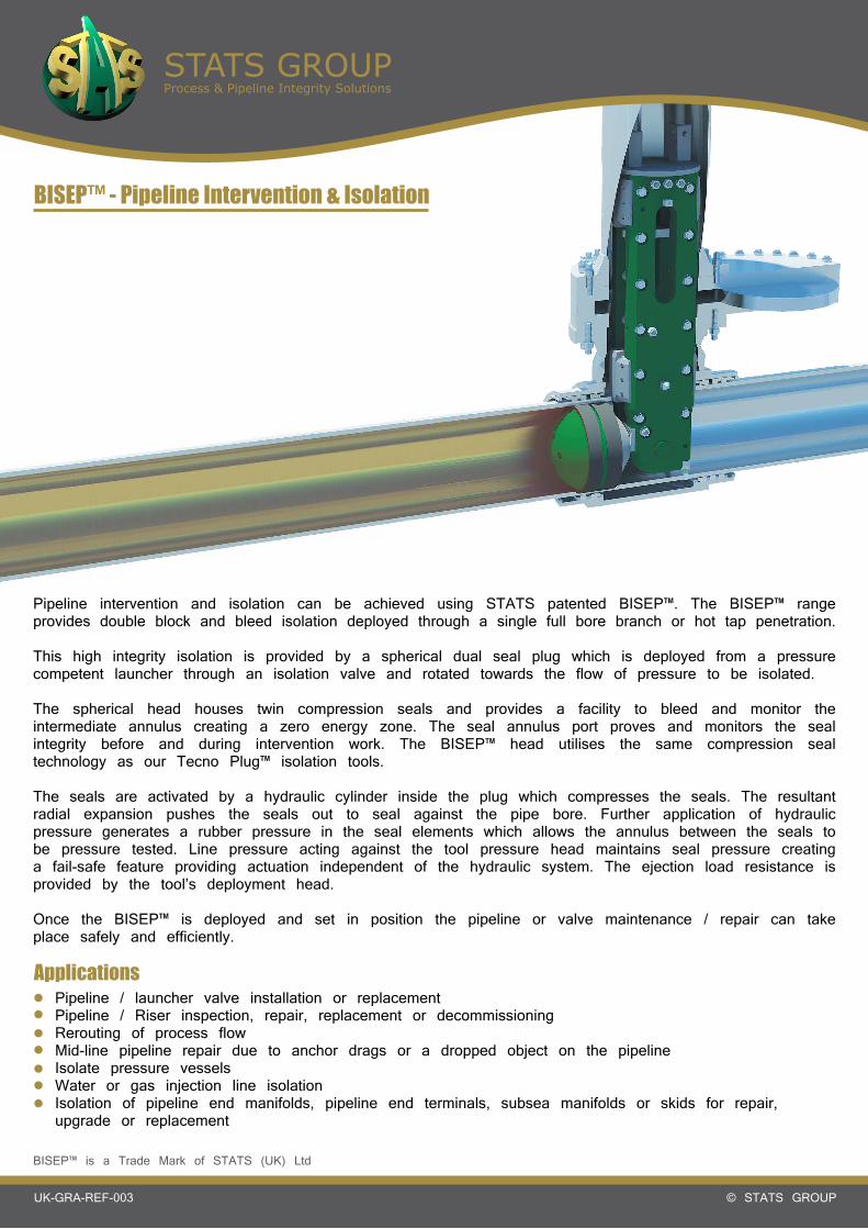
BISEP™ - Pipeline Intervention & Isolation
Pipeline intervention and isolation can be achieved using STATS patented BISEP™. The BISEP™ range provides double block and bleed isolation deployed through a single full bore branch or hot tap penetration.
This high integrity isolation is provided by a spherical dual seal plug which is deployed from a pressure competent launcher through an isolation valve and rotated towards the flow of pressure to be isolated.
The spherical head houses twin compression seals and provides a facility to bleed and monitor the intermediate annulus creating a zero energy zone. The seal annulus port proves and monitors the seal integrity before and during intervention work. The BISEP™ head utilises the same compression seal technology as our Tecno Plug™ isolation tools.
The seals are activated by a hydraulic cylinder inside the plug which compresses the seals. The resultant radial expansion pushes the seals out to seal against the pipe bore. Further application of hydraulic pressure generates a rubber pressure in the seal elements which allows the annulus between the seals to be pressure tested. Line pressure acting against the tool pressure head maintains seal pressure creating a fail-safe feature providing actuation independent of the hydraulic system. The ejection load resistance is provided by the tool’s deployment head.
Once the BISEP™ is deployed and set in position the pipeline or valve maintenance / repair can take place safely and efficiently.
Pipeline / launcher valve installation or replacementPipeline / Riser inspection, repair, replacement or decommissioningRerouting of process flowMid-line pipeline repair due to anchor drags or a dropped object on the pipelineIsolate pressure vesselsWater or gas injection line isolationIsolation of pipeline end manifolds, pipeline end terminals, subsea manifolds or skids for repair, upgrade or replacement
Applications
BISEP™ is a Trade Mark of STATS (UK) Ltd

STATS GROUPProcess & Pipeline Integrity Solutions
© STATS GROUPUK-GRA-REF-003
BISEP™ - Pipeline Intervention & IsolationOperator Benefits
Dramatically increases safety over traditional line stop technologySingle operation significantly reduces costs (Single fitting, welding, inspection, scaffolding, crane and excavation costs)Single operation significantly reduces workscope timescales, resulting in reduced shutdown timeSingle fitting allows installation in restricted access piping Reduced inspection / quality control / hot work permits (single fitting)BISEP™ technology complies with operator double block and bleed requirementsMinimised production disruption on interconnected pipeline networks during valve repairs or tie-ins
Annulus bleed port proves and monitors the seal integrity before and during any intervention workIsolation integrity monitored through annulus, hydraulic set circuit and body vents continuouslyDesign provides axial restraint through bearing on dual clevis plates (no single point failure)Seal annulus bleed provides Zero Energy ZoneDual compression seals are more compliant and have a far higher success rate than traditional cup seals particularly in pitted pipeworkSelf-Energisation of seals maintains isolation integrity independent of hydraulic control circuitNegates the need for additional hot taps for bleed functionCan accommodate reinstatement pressure test against the rear of the set BISEP™BISEP™ isolation installed upstream of fitting, maintaining fitting in safe zone during workscopeBISEP™ launcher ported to facilitate venting, purging and flushing of isolated sectionCan be deployed through conventional equal tee, clamp or branchSize range: 3”– 36”. Pressure range: up to 150 Bar / 2175 psiDesign allows for deployment in high flow conditions
Key Features
STATS can provide operators a full turnkey service, supplying permanent or temporary tie-in clamps (mechanical or welded fitting) with a branch diameter and angle to suit application, along with STATS patented dual seal slab valves and hot tapping services. Once the BISEP™ is recovered, STATS can provide a completion plug to provide permanent isolation to the branch off-take and enable the removal of the slab valve allowing a blind flange to be fitted to the tie-in clamp.
Fully verifiable Double Block & Bleed isolation through a single intervention point:
12” 300# BISEP™18” 300# BISEP™ Installation
BISEP™ is a Trade Mark of STATS (UK) Ltd

STATS GROUPProcess & Pipeline Integrity Solutions
© STATS GROUPUK-GRA-REF-003
BISEP™ - Data
BISEP™ Nominal Diameter
BISEP™ SealOutside Diameter
Pipe Inside Diameter(Min-Max)
3” 67mm (2.6”) 74-83mm (2.9-3.3”)
4” 94mm (3.7”) 97-102mm (3.8-4.0”)
6” 175mm (6.9”) 193-203mm (7.6-8.0”)
8” 185mm (7.3”) 188-205mm (7.4-8.1”)
10” 225mm (8.9”) 226-245mm (8.9-9.6”)
10” 252mm (9.5”) 243-262mm (9.6-10.3”)
12” 262mm (9.9”) 262-280mm (10.3-11.0”)
12” 276mm (10.9”) 277-299mm (10.9-11.8”)
12” 294mm (11.6”) 296-317mm (11.7-12.5”)
14” 313mm (12.3”) 317-338mm (12.5-13.7”)
14” 323mm (12.7”) 327-348mm (12.9-13.7”)
16” 346mm (13.6”) 349-376mm (13.7-14.8”)
16” 362mm (14.3”) 365-392mm (14.4-15.4”)
18” 372mm (14.6”) 376-404mm (14.8-15.9”)
18” 397mm (15.6”) 404-432mm (15.9-17.0”)
20” 419mm (16.5”) 427-454mm (16.8-17.9”)
20” 445mm (17.5”) 455-482mm (17.9-19.0”)
22” 470mm (18.5”) 481-507mm (18.9-20.0”)
22” 496mm (19.5”) 509-536mm (20.0-21.1”)
24” 521mm (20.5”) 535-561mm (21.1-22.1”)
24” 547mm (21.5”) 558-592mm (22.0-23.3”)
26” 572mm (22.5”) 584-617mm (23.0-24.3”)
26” 598mm (23.5”) 612-648mm (24.1-25.5”)
28” 623mm (24.5”) 639-673mm (25.2-26.5”)
28” 648mm (25.5”) 662-698mm (26.1-27.5”)
30” 673mm (26.5”) 692-723mm (27.2-28.5”)
30” 699mm (27.5”) 716-749mm (28.2-29.5”)
32” 724mm (28.5”) 746-774mm (29.4-30.5”)
34” 775mm (30.5”) 800-825mm (31.5-32.5”)
36” 801mm (31.5”) 824-851mm (32.4-33.5”)
36” 826mm (32.5”) 853-876mm (33.6-34.5”)
All data correct at time of publicationSizes may vary due to integration with other products
BISEP™ is a Trade Mark of STATS (UK) Ltd

STATS GROUPProcess & Pipeline Integrity Solutions
© STATS GROUPUK-GRA-REF-003
Tecno Plug™ - Data
Plug Nominal Diameter
Plug Outside Diameter
A - Pipe ID (Min-Max)
B - Overall Length
C - Seal To Lock (Unset)* Weight
6” 130mm 140 - 150mm 274mm 177mm 15kg
6” 143mm 153 - 163mm 285mm 189mm 19kg
8” 163mm 173 - 193mm 326mm 205mm 30kg
8” 190mm 200 - 230mm 257mm 207mm 33kg
10” 210mm 220 - 245mm 372mm 248mm 50kg
10” 235mm 245 - 268mm 372mm 249mm 57kg
12” 277mm 287 - 301mm 578mm 307mm 112kg
12” 293mm 303 - 317mm 578mm 307mm 123kg
14” 294mm 318 - 332mm 578mm 308mm 128kg
14” 308mm 328 - 358mm 578mm 308mm 130kg
16” 346mm 356 - 376mm 683mm 355mm 197kg
16” 366mm 376 - 396mm 683mm 355mm 218kg
18” 388mm 398 - 423mm 683mm 357mm 262kg
18” 405mm 415 - 440mm 683mm 358mm 264kg
20” 430mm 440 - 465mm 751mm 391mm 355kg
20” 450mm 460 - 500mm 676mm 392mm 403kg
22” 480mm 490 - 530mm 676mm 393mm 405kg
22” 500mm 510 - 550mm 676mm 395mm 426kg
24” 520mm 530 - 570mm 947mm 457mm 681kg
24” 550mm 560 - 600mm 947mm 458mm 755kg
26” 595mm 605 - 645mm 967mm 460mm 833kg
30” 625mm 635 - 675mm 1025mm 584mm 986kg
30” 644mm 654 - 694mm 1025mm 584mm 1062kg
30” 694mm 704 - 744mm 1025mm 587mm 1201kg
32” 744mm 754 - 794mm 1156mm 674mm 1567kg
34” 770mm 780 - 820mm 1151mm 671mm 1686kg
34” 794mm 804 - 844mm 1151mm 674mm 1785kg
36” 825mm 835 - 875mm 1105mm 705mm 2039kg
36” 869mm 879 - 919mm 1105mm 705mm 2180kg
All data correct at time of publication
* Dimension B reduces by approximately 15-20% when the tool is in the set position
Tecno Plug™ is a Trade Mark of STATS (UK) Ltd
STATS GROUPProcess & Pipeline Integrity Solutions
© STATS GROUPUK-GRA-REF-003
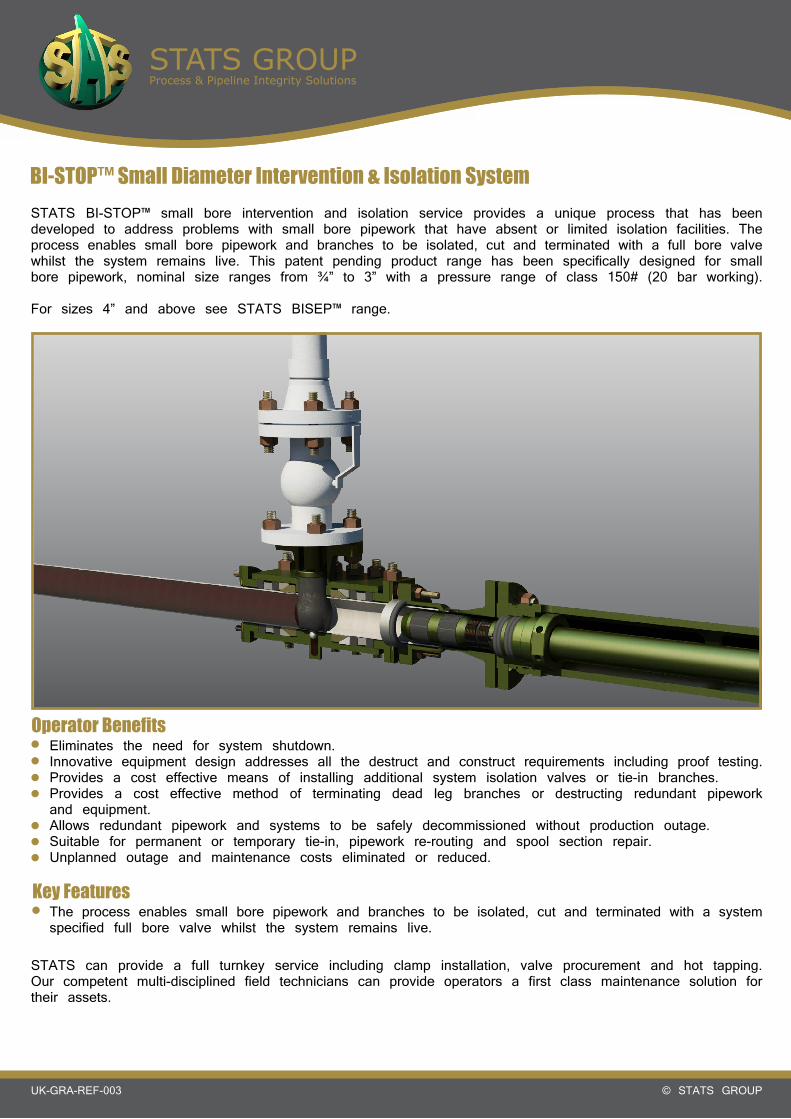
BI-STOP™ Small Diameter Intervention & Isolation SystemSTATS BI-STOP™ small bore intervention and isolation service provides a unique process that has been developed to address problems with small bore pipework that have absent or limited isolation facilities. The process enables small bore pipework and branches to be isolated, cut and terminated with a full bore valve whilst the system remains live. This patent pending product range has been specifically designed for small bore pipework, nominal size ranges from ¾” to 3” with a pressure range of class 150# (20 bar working).
For sizes 4” and above see STATS BISEP™ range.
Operator BenefitsEliminates the need for system shutdown.Innovative equipment design addresses all the destruct and construct requirements including proof testing.Provides a cost effective means of installing additional system isolation valves or tie-in branches.Provides a cost effective method of terminating dead leg branches or destructing redundant pipework and equipment.Allows redundant pipework and systems to be safely decommissioned without production outage.Suitable for permanent or temporary tie-in, pipework re-routing and spool section repair.Unplanned outage and maintenance costs eliminated or reduced.
Key FeaturesThe process enables small bore pipework and branches to be isolated, cut and terminated with a system specified full bore valve whilst the system remains live.
STATS can provide a full turnkey service including clamp installation, valve procurement and hot tapping. Our competent multi-disciplined field technicians can provide operators a first class maintenance solution for their assets.

STATS GROUPProcess & Pipeline Integrity Solutions
© STATS GROUPUK-GRA-REF-003
Mechanical Tie-In ClampMechanical Tie-In Clamps allow the connection of new branch pipework to existing infrastructure without the requirement for welding. Tie-In Clamps are routinely used to provide a flanged off-take to enable hot or cold tapping into an existing pipe with no interruption to production. The clamps can also be utilised as an access point for double block and bleed BISEP™ line isolation.
The clamps feature a dual seal arrangement which provides an annulus cavity to fully verify seal integrity prior to hot tapping. Compression flanges mechanically actuate the seals and drive taper locks which grip the pipe, providing axial restraint.
The clamp components are compatible with a wide range of fluid types and flow conditions and are designed for ease of installation with minimal disruption to the pipework or system to which they are fitted. STATS can provide a full turnkey service including clamp installation and hot tapping. STATS can provide a completion plug to provide permanent isolation to the branch off-take and enable the removal of the slab valve allowing a blind flange to be fitted to the tie-in clamp.
Key FeaturesSize range: standard pipe sizes 3” – 46”Full range of reducing branch sizes availableBranch angle to suit applicationPressure range: up to ASME 900#Can be utilised for hot tapping or line isolationDual seal design with annulus test facilityStructural locks / grout injection to suit applicationNo hot work required 18” x 18” 300# Tie-In Clamp

STATS GROUPProcess & Pipeline Integrity Solutions
© STATS GROUPUK-GRA-REF-003
In-Line Weld Test Tool - Hydrostatic Test
Operator Benefits
Simple, straight forward installation and operationInstalled and activated in a matter of minutesLarge section high quality elastomer seals ensure a leak tight seal, even in pitted pipeworkDesigned with generous radial clearance to cope with typical internal obstructions such as weld beads, ovality, etcEasily installed pre hot-work operations to provide a verified vapour barrierSuitable for use with most test mediums (liquid or gas)High performance elastomer seals provide excellent radial expansion and relaxation properties, even after many operating cyclesRobust construction ensures years of trouble free operation even in the harshest environmentsSuitable for installation in horizontal, vertical and inclined piping
Key Features
In-Line Weld Test Tools are commonly used during the maintenance and modification of piping or processequipment, enabling hydrostatic pressure testing. Inserted into the piping or equipment component to be tested, In-Line Weld Test Tools provide a fast and efficient method of verifying the integrity of butt welds, joints or other welded pipe components. In-Line Weld Test Tools can also provide a verified vapour barrier against the migration of flammable vapours, allowing hot-work activities to take place safely onsite.
Reduces system downtime and increases worksite safety by minimising pressure test volumeOperators save time and reduce costs by limiting test area to only the new weld or welded componentTimely completion of maintenance & modification activitiesNo requirement to flood & de-water gas systemsNo requirement for full system pressurisation beneficial to ‘mature’ systems by decreasing potential for spading / leakageInstalled and activated in a matter of minutesSale or rental options available, complete with full ancillary equipmentFully certified client training provided by highly trained STATS personnel to support Weld Test Tool hire
Size range: common pipe sizes ¾”- 36” as standard. Sizes up to 72” available on requestHydraulically actuated above 2”Pressure range up to 690 Bar / 10,000 psi dependent on specification, maximum test pressure to suit systemPressure assisted sealing
Specification
Verified Vapour Barrier Hydrostatic Weld Test
4” In-Line Weld Test Tool

STATS GROUPProcess & Pipeline Integrity Solutions
© STATS GROUPUK-GRA-REF-003
Flanged Weld Test Tool - Hydrostatic Test
Operator Benefits
Simple, straight forward installation and operationEasily installed, activated in a matter of minutesLarge section high quality elastomer seals ensure a leak tight seal, even in pitted pipeworkDesigned with generous radial clearance to cope with typical internal obstructions such as weld beads / ovalityTools can be configured to suit applications where hydrotest is required on butt weld between flange and welded fitting such as an elbow or teeSuitable for use with most test mediums (liquid or gas)High performance elastomer seals provide excellent radial expansion and relaxation properties, even after many operating cyclesRobust construction ensures years of trouble free operation even in the harshest environmentsSuitable for installation in horizontal, vertical and inclined piping
Key Features
Flanged Weld Test Tools enable localised pressure testing of new flange welds. These tools minimise the test system limits and reduce the time required to undertake maintenance or modification work. The tools are designed with a single seal and flange configuration and are available in a range of sizes compatible with common pipe schedules and flange types / sizes. Specially configured tools in sizes up to 48” may be engineered and designed for specific applications.
Reduces system downtime and increases worksite safety by minimising pressure test volumeOperators save time and reduce costs by limiting test area to only the new weld or welded componentTimely completion of maintenance and modification activitiesNo requirement to flood and de-water gas systemsNo requirement for full system pressurisation beneficial to ‘mature’ systems by decreasing potential for spading / leakageEasily installed, activated in a matter of minutesSale or rental options available, complete with full ancillary equipmentFully certified client training provided by highly trained STATS personnel to support Weld Test Tool hire
Size range: common pipe sizes ½”- 36” as standard. Sizes up to 48” available on requestHydraulically actuated above 2”Designed to provide recommended test pressure requirements up to ASME 2500#Separate fill and vent portsPressure assisted sealing
Specification
Flanged Weld Test Tool Hydrotest
18” 150# Flanged Weld Test Tool
2” Mechanical Flanged Weld Test Tool

STA
TS G
RO
UP
Proc
ess
& P
ipel
ine
Inte
grity
Sol
utio
ns
© STATS GROUP
UK-GRA-REF-003
In-Li
ne W
eld T
est T
ool -
Inte
rface
Dim
ensio
ns
Mechanical In-Line Weld Test Tool
¾” up to 2”
Hydraulic In-Line Weld Test Tool
3” up to 36”
Tool
Ref
S
ize
Tool
Mod
el
Nu
mb
erTo
ol D
iam
eter
Com
pat
ible
Pip
e S
ched
ule
sTo
ol M
axim
um
Wor
kin
g
Pre
ssu
reO
vera
ll Le
ng
th -
ALe
ng
th B
etw
een
S
eals
-B
Wei
gh
t
¾”
TT00
1313
mm
- 0
.51”
¾”
XS,
80,
80s
600
Bar
- 8
700
psi
222m
m -
8.7
4”86
mm
-3.
39”
0.5k
g -
1lbs
¾”
TT00
1717
.6m
m -
0.6
9”¾
” 30
, 40
, 40
s, S
td50
0 Bar
- 7
250
psi
222m
m -
8.7
4”86
mm
-3.
39”
0.5k
g -
1lbs
¾”
TT00
2121
.3m
m -
0.8
4”¾
” 5,
5s,
10,
10s
400
Bar
- 5
800
psi
222m
m -
8.7
4”86
mm
-3.
39”
0.5k
g -
1lbs
1”TT
0017
17.6
mm
- 0
.69”
1” 1
6055
0 Bar
- 7
975
psi
222m
m -
8.7
4”86
mm
-3.
39”
0.5k
g -
1lbs
1”TT
0021
21.3
mm
- 0
.84”
1” 1
0, 1
0s,
30,
40,
Std
, XS,
80,
80s
550
Bar
- 7
975
psi
245m
m -
9.6
5”90
mm
- 3
.39”
1kg
- 2.
2lbs
1”TT
0027
27m
m -
1.0
6”1”
5,
5s55
0 Bar
- 7
975
psi
245m
m -
9.6
5”90
mm
- 3
.39”
1kg
- 2.
2lbs
1½”
TT00
2121
.3m
m -
0.8
4”1½
” XXS
550
Bar
- 7
975
psi
245m
m -
9.6
5”90
mm
- 3
.39”
1kg
- 2.
2lbs
1½”
TT00
2727
mm
- 1
.06”
1½”
160
350
Bar
- 5
075
psi
245m
m -
9.6
5”90
mm
- 3
.39”
1kg
- 2.
2lbs
1½”
TT00
3434
mm
- 1
.34”
1½”
30,
40,
40s,
Std
, XS,
80,
80s
800
Bar
- 1
1600
psi
280m
m -
11.
02”
100m
m -
3.9
4”1k
g -
2.2l
bs
1½”
TT00
3737
mm
- 1
.45”
1½”
5, 5
s, 1
0, 1
0s60
0 Bar
- 8
700
psi
280m
m -
11.
02”
100m
m -
3.9
4”1k
g -
2.2l
bs
2”TT
0034
34m
m -
1.3
4”2”
XXS
1000
Bar
- 1
4500
psi
280m
m -
11.
02”
100m
m -
3.9
4”1k
g -
2.2l
bs
2”TT
0037
37m
m -
1.4
5”2”
160
750
Bar
- 1
0875
psi
280m
m -
11.
02”
100m
m -
3.9
4”1k
g -
2.2l
bs
2”TT
0045
45m
m -
1.7
7”2”
5,
5s,
10,
10s,
30,
40,
Std
, XS,
80,
80s
400
Bar
- 5
800
psi
280m
m -
11.
02”
100m
m -
3.9
4”1k
g -
2.2l
bs
All data correct at time of publication

Tool
Ref
Siz
eTo
ol M
odel
Nu
mb
erTo
ol D
iam
eter
Com
pat
ible
Pip
e S
ched
ule
sTo
ol M
axim
um
Wor
kin
g P
ress
ure
Ove
rall
Len
gth
- A
Len
gth
Bet
wee
n
Sea
ls-
BW
eig
ht
3”TT
0054
54.9
mm
- 2
.16”
3” X
XS
240
Bar
- 3
480
psi
200m
m -
7.8
7”94
mm
- 3
.70”
5kg
- 11
lbs
3”TT
0062
62.6
mm
- 2
.46”
3” 1
6014
0 Bar
- 2
030
psi
200m
m -
7.8
7”94
mm
- 3
.70”
5kg
- 11
lbs
3”TT
0069
69.7
mm
- 2
.74”
3” X
S, 8
0, 8
0s10
0 Bar
- 1
450
psi
200m
m -
7.8
7”94
mm
- 3
.70”
5kg
- 11
lbs
3”TT
0073
73m
m -
2.8
7”3”
30,
Std
, 40
, 40
s60
0 Bar
- 8
700
psi
206m
m -
8.1
1”12
0mm
- 4
.72”
6.5k
g -
14lb
s
3”TT
0078
78.8
mm
- 3
.10”
3” 1
0, 1
0s52
5 Bar
- 7
612
psi
206m
m -
8.1
1”12
0mm
- 4
.72”
6.5k
g -
14lb
s
3”TT
0081
81m
m -
3.1
9”3”
5,
5s47
5 Bar
- 6
887
psi
206m
m -
8.1
1”12
0mm
- 4
.72”
6.5k
g -
14lb
s
4”TT
0073
73m
m -
2.8
7”4”
XXS
550
Bar
- 7
975
psi
206m
m -
8.1
1”12
0mm
- 4
.72”
6.5k
g -
14lb
s
4”TT
0081
81m
m -
3.1
9”4”
160
425
Bar
- 6
162
psi
206m
m -
8.1
1”12
0mm
- 4
.72”
6.5k
g -
14lb
s
4”TT
0086
86m
m -
3.3
8”4”
120
350
Bar
- 5
075
psi
206m
m -
8.1
1”12
0mm
- 4
.72”
6.5k
g -
14lb
s
4”TT
0091
91.2
mm
- 3
.59”
4” X
S, 8
0, 8
0s32
5 Bar
- 4
712
psi
206m
m -
8.1
1”12
0mm
- 4
.72”
6.5k
g -
14lb
s
4”TT
0096
96.3
mm
- 3
.79”
4” 3
0, S
td,
40,
40s
275
Bar
- 3
987
psi
206m
m -
8.1
1”12
0mm
- 4
.72”
6.5k
g -
14lb
s
4”TT
0102
102.
5mm
- 4
.03”
4” 5
, 5s
, 10
, 10
s22
5 Bar
- 3
262
psi
206m
m -
8.1
1”12
0mm
- 4
.72”
6.5k
g -
14lb
s
5”TT
0096
96.3
mm
- 3
.79”
5” X
XS
275
Bar
- 3
987
psi
206m
m -
8.1
1”12
0mm
- 4
.72”
6.5k
g -
14lb
s
5”TT
0102
102.
5mm
- 4
.03”
5” 1
20,
160
225
Bar
- 3
262
psi
206m
m -
8.1
1”12
0mm
- 4
.72”
6.5k
g -
14lb
s
5”TT
0124
124.
3mm
- 4
.89”
5” 5
, 5s
, 10
, 10
s, S
td,
40,
40s
500
Bar
- 7
250
psi
308m
m -
12.
1”19
7mm
- 7
.76”
24kg
- 5
3lbs
5”TT
0116
116.
9mm
- 4
.60”
5” X
S, 8
0, 8
0s65
0 Bar
- 9
425
psi
308m
m -
12.
1”19
7mm
- 7
.76”
24kg
- 5
3lbs
6”TT
0154
154.
6mm
- 6
.08”
6” 5
, 5s
, 10
, 10
s30
0 Bar
- 4
350
psi
308m
m -
12.
1”19
7mm
- 7
.76”
24kg
- 5
3lbs
6”TT
0146
146.
6mm
-5.
77”
6” S
td,
40,
40s
350
Bar
- 5
075
psi
308m
m -
12.
1”19
7mm
- 7
.76”
24kg
- 5
3lbs
6”TT
0138
138.
9mm
- 5
.47”
6” X
S, 8
0, 8
0s40
0 Bar
- 5
800
psi
308m
m -
12.
1”19
7mm
- 7
.76”
24kg
- 5
3lbs
6”TT
0132
132.
2mm
- 5
.20”
6” 1
2045
0 Bar
- 6
525
psi
308m
m -
12.
1”19
7mm
- 7
.76”
24kg
- 5
3lbs
6”TT
0124
124.
3mm
- 4
.89”
6” 1
6055
0 Bar
- 7
975
psi
308m
m -
12.
1”19
7mm
- 7
.76”
24kg
- 5
3lbs
6”TT
0116
116.
9mm
- 4
.60”
6” X
XS
650
Bar
- 9
425
psi
308m
m -
12.
1”19
7mm
- 7
.76”
24kg
- 5
3lbs
8”TT
0204
204.
7mm
- 8
.06”
8” 5
, 5s
, 10
, 10
s50
0 Bar
- 7
250
psi
413m
m -
16.
26”
269m
m -
10.
59”
60kg
- 1
32lb
s
8”TT
0190
190.
5mm
- 7
.50”
8” S
td,
20,
30,
40,
40s,
60
550
Bar
- 7
975
psi
413m
m -
16.
26”
269m
m -
10.
59”
60kg
- 1
32lb
s
8”TT
0180
180.
9mm
- 7
.12”
8” X
S, 8
0, 8
0s,
100
700
Bar
- 1
0150
psi
413m
m -
16.
26”
269m
m -
10.
59”
60kg
- 1
32lb
s
8”TT
0174
174.
6mm
- 6
.87”
8” 1
2080
0 Bar
- 1
1600
psi
413m
m -
16.
26”
269m
m -
10.
59”
60kg
- 1
32lb
s
8”TT
0165
165.
8mm
- 6
.53”
8” 1
40,
160,
XXS
900
Bar
- 1
3050
psi
413m
m -
16.
26”
269m
m -
10.
59”
60kg
- 1
32lb
s
STA
TS G
RO
UP
Proc
ess
& P
ipel
ine
Inte
grity
Sol
utio
ns
© STATS GROUP
UK-GRA-REF-003
All data correct at time of publication

STA
TS G
RO
UP
Proc
ess
& P
ipel
ine
Inte
grity
Sol
utio
ns
© STATS GROUP
UK-GRA-REF-003
Tool
Ref
S
ize
Tool
Mod
el
Nu
mb
erTo
ol D
iam
eter
Com
pat
ible
Pip
e S
ched
ule
sTo
ol M
axim
um
W
orki
ng
Pre
ssu
reO
vera
ll Le
ng
th -
ALe
ng
th B
etw
een
S
eals
-B
Wei
gh
t
10”
TT02
0420
4.7m
m -
8.0
6”10
” 16
050
0 Bar
- 7
250
psi
413m
m -
16.
26”
269m
m -
10.
59”
60kg
- 1
32lb
s
10”
TT02
1221
2.3m
m -
8.3
5”10
” 14
0, X
XS
450
Bar
- 6
525
psi
413m
m -
16.
26”
269m
m -
10.
59”
60kg
- 1
32lb
s
10”
TT02
2022
0.2m
m -
8.6
7”10
” 12
040
0 Bar
- 5
800
psi
413m
m -
16.
26”
269m
m -
10.
59”
60kg
- 1
32lb
s
10”
TT02
2622
6.6m
- 8
.92”
10”
100
375
Bar
-
5437
psi
413m
m -
16.
26”
269m
m -
10.
59”
60kg
- 1
32lb
s
10”
TT02
3323
3mm
- 9
.17”
10”
XS,
60,
80,
80s
1000
Bar
- 1
4500
psi
499m
m -
19.
65”
269m
m -
10.
59”
160k
g -
353l
bs
10”
TT02
4324
3.5m
m -
9.5
8”10
” Std
, 40
, 40
s95
0 Bar
- 1
3775
psi
499m
m -
19.
65”
269m
m -
10.
59”
160k
g -
353l
bs
10”
TT02
4624
6mm
- 9
.68”
10”
20,
3090
0 Bar
- 1
3050
psi
499m
m -
19.
65”
269m
m -
10.
59”
160k
g -
353l
bs
10”
TT02
5325
3.7m
m -
9.9
9”10
” 5,
5s,
10,
10s
800
Bar
- 1
1600
psi
499m
m -
19.
65”
269m
m -
10.
59”
160k
g -
353l
bs
12”
TT02
4324
3.5m
m -
9.5
8”12
” 16
095
0 Bar
- 1
3775
psi
499m
m -
19.
65”
269m
m -
10.
59”
160k
g -
353l
bs
12”
TT02
6026
0mm
- 1
0.23
”12
” 12
0, 1
40,
XXS
750
Bar
- 1
0875
psi
499m
m -
19.
65”
269m
m -
10.
59”
160k
g -
353l
bs
12”
TT02
7027
0mm
- 1
0.63
”12
” 10
065
0 Bar
- 9
425
psi
499m
m -
19.
65”
269m
m -
10.
59”
160k
g -
353l
bs
12”
TT02
7727
7mm
- 1
0.90
”12
” 80
600
Bar
- 8
700
psi
499m
m -
19.
65”
269m
m -
10.
59”
160k
g -
353l
bs
12”
TT02
8528
5mm
- 1
1.22
”12
” XS,
60,
80s
550
Bar
- 7
975
psi
499m
m -
19.
65”
269m
m -
10.
59”
160k
g -
353l
bs
12”
TT02
9129
1mm
-11
.45”
12”
40,4
0s50
0 Bar
- 7
250
psi
499m
m -
19.
65”
269m
m -
10.
59”
180k
g -
397l
bs
12”
TT02
9529
5mm
- 1
1.61
”12
” Std
, 30
500
Bar
- 7
250
psi
499m
m -
19.
65”
269m
m -
10.
59”
180k
g -
397l
bs
12”
TT03
0030
0mm
- 1
1.81
”12
” 10
, 10
s, 2
045
0 Bar
-65
25 p
si49
9mm
- 1
9.65
”26
9mm
- 1
0.59
”18
0kg
- 39
7lbs
12”
TT03
0430
4mm
- 1
1.96
”12
” 5,
5s
450
Bar
-65
25 p
si49
9mm
- 1
9.65
”26
9mm
- 1
0.59
”18
0kg
- 39
7lbs
14”
TT02
7027
0mm
- 1
0.63
”14
” 16
065
0 Bar
- 9
425
psi
499m
m -
19.
65”
269m
m -
10.
59”
180k
g -
397l
bs
14”
TT02
7727
7mm
- 1
0.90
”14
” 14
057
5 Bar
- 8
337
psi
499m
m -
19.
65”
269m
m -
10.
59”
180k
g -
397l
bs
14”
TT02
8528
5mm
- 1
1.22
”14
” 12
055
0 Bar
- 7
975
psi
499m
m -
19.
65”
269m
m -
10.
59”
180k
g -
397l
bs
14”
TT02
9529
5mm
- 1
1.61
”14
” 10
050
0 Bar
- 7
250
psi
499m
m -
19.
65”
269m
m -
10.
59”
180k
g -
397l
bs
14”
TT03
0430
4mm
- 1
1.96
”14
” 80
450
Bar
- 6
525
psi
499m
m -
19.
65”
269m
m -
10.
59”
180k
g -
397l
bs
14”
TT03
1131
1mm
-12
.24”
14”
6042
5 Bar
- 6
162
psi
499m
m -
19.
65”
269m
m -
10.
59”
180k
g -
397l
bs
14”
TT03
1631
6mm
- 1
2.44
”14
” XS
400
Bar
- 5
800
psi
499m
m -
19.
65”
269m
m -
10.
59”
180k
g -
397l
bs
14”
TT03
2232
2mm
- 1
2.67
”14
” Std
, 20
, 30
, 40
375
Bar
- 5
437
psi
499m
m -
19.
65”
269m
m -
10.
59”
180k
g -
397l
bs
14”
TT03
3233
2mm
- 1
3.07
”14
” 5,
5s,
10,
10s
350
Bar
- 5
075
psi
499m
m -
19.
65”
269m
m -
10.
59”
180k
g -
397l
bs
In-Li
ne W
eld T
est T
ool -
Inte
rface
Dim
ensio
ns
All data correct at time of publication

STA
TS G
RO
UP
Proc
ess
& P
ipel
ine
Inte
grity
Sol
utio
ns
© STATS GROUP
UK-GRA-REF-003
Tool
Ref
Siz
eTo
ol M
odel
N
um
ber
Tool
Dia
met
erC
omp
atib
le P
ipe
Sch
edu
les
Tool
Max
imu
m
Wor
kin
g P
ress
ure
Ove
rall
Len
gth
- A
Len
gth
Bet
wee
n
Sea
ls -
BW
eig
ht
16”
TT03
1131
1mm
-12
.24”
16”
160
1000
Bar
- 1
4500
psi
748m
m -
29.
45”
462m
m -
18.
18”
380k
g -
838l
bs
16”
TT03
1931
9mm
- 1
2.56
”16
” 14
010
00 B
ar -
145
00 p
si74
8mm
- 2
9.45
”46
2mm
- 1
8.18
”38
0kg
- 83
8lbs
16”
TT03
3033
0mm
- 1
2.99
”16
” 12
010
00 B
ar -
145
00 p
si74
8mm
- 2
9.45
”46
2mm
- 1
8.18
”38
0kg
- 83
8lbs
16”
TT03
3933
9mm
- 1
3.34
”16
” 10
090
0 Bar
- 1
3050
psi
748m
m -
29.
45”
462m
m -
18.
18”
380k
g -
838l
bs
16”
TT03
5035
0.5m
m -
17.
80”
16”
8087
5 Bar
- 1
2687
psi
748m
m -
29.
45”
462m
m -
18.
18”
380k
g -
838l
bs
16”
TT03
5835
8mm
- 1
4.09
”16
” 60
825
Bar
- 1
1962
psi
748m
m -
29.
45”
462m
m -
18.
18”
380k
g -
838l
bs
16”
TT03
6436
4.8m
m -
14.
36”
16”
XS,
40
750
Bar
- 1
0875
psi
748m
m -
29.
45”
462m
m -
18.
18”
380k
g -
838l
bs
16”
TT03
7337
3mm
-14
.68”
16”
Std
, 20
, 30
, 40
700
Bar
- 1
0150
psi
748m
m -
29.
45”
462m
m -
18.
18”
380k
g -
838l
bs
16”
TT03
8138
1.2m
m -
15.0
0”16
” 5,
5s,
10,
10s
650
Bar
- 9
425
psi
748m
m -
29.
45”
462m
m -
18.
18”
380k
g -
838l
bs
18”
TT03
5035
0.5m
m -
17.
80”
18”
160
875
Bar
- 1
2687
psi
748m
m -
29.
45”
462m
m -
18.
18”
380k
g -
838l
bs
18”
TT03
5835
8mm
- 1
4.09
”18
” 14
075
0 Bar
- 1
0875
psi
748m
m -
29.
45”
462m
m -
18.
18”
380k
g -
838l
bs
18”
TT03
6436
4.8m
m -
14.
36”
18”
120
700
Bar
- 1
0150
psi
748m
m -
29.
45”
462m
m -
18.
18”
380k
g -
838l
bs
18”
TT03
8838
8mm
-15
.28”
18”
30,
XS,
40,
60,
80,
100
425
Bar
- 6
162
psi
600m
m -
23.
6”32
0mm
- 1
2.59
”39
5kg
- 87
0lbs
18”
TT04
3043
0mm
- 1
6.93
”18
” 5,
5s,
10,
10s
20,
Std
375
Bar
- 5
437
psi
600m
m -
23.
6”31
5mm
- 1
2.40
”39
5kg
- 87
0lbs
20”
TT03
8838
8mm
-15
.28”
20”
120,
140
, 16
045
0 Bar
- 6
525
psi
600m
m -
23.
6”32
0mm
- 1
2.59
”39
5kg
- 87
0lbs
20”
TT04
3043
0mm
- 1
6.93
”20
” 60
, 80
, 10
032
5 Bar
- 4
712
psi
600m
m -
23.
6”31
5mm
- 1
2.40
”45
0kg
- 99
1lbs
20”
TT04
7847
8mm
- 1
8.81
”20
” 20
, Std
, 10
, 10
s, 5
, 5s
900
Bar
- 1
3050
psi
710m
m -
27.
95”
345m
m -
13.
58”
725k
g -
1600
lbs
22”
TT04
3043
0mm
- 1
6.93
”22
” 16
0, 1
4032
5 Bar
- 4
712
psi
600m
m -
23.
6”31
5mm
- 1
2.40
”45
0kg
- 99
1lbs
22”
TT04
7843
0mm
- 1
6.93
”22
” 10
0, 8
0, 6
010
00 B
ar -
145
00 p
si71
0mm
- 2
7.95
”34
5mm
- 1
3.58
”45
0kg
- 99
1lb
22”
TT05
2052
0mm
- 2
0.47
”22
” 5,
5s,
10,
10s
, Std
, 20
, XS,
30
550
Bar
-
7975
psi
710m
m -
27.
95”
345m
m -
13.
58”
760k
g -
1674
lbs
24”
TT04
7847
8mm
- 1
8.81
”24
” 12
0, 1
40,
160
850
Bar
- 1
2325
psi
710m
m -
27.
95”
345m
m -
13.
58”
725k
g -
1600
lbs
24”
TT05
2052
0mm
- 2
0.47
”24
” 10
0, 8
0, 6
050
0 Bar
- 7
250
psi
710m
m -
27.
95”
345m
m -
13.
58”
760k
g -
1674
lbs
24”
TT05
5055
0mm
- 2
1.65
”24
” Std
, 20
, XS,
30,
40
400
Bar
- 5
800
psi
710m
m -
27.
95”
345m
m -
13.
58”
825k
g -
1817
lbs
28”
TT06
6066
0mm
- 2
5.98
”28
” XS,
20,
30
250
Bar
- 3
625
psi
844m
m -
33.
23”
412m
m -
16.
22”
1180
kg -
260
0lbs
28”
TT06
8068
0mm
- 2
6.77
”28
” 10
, Std
250
Bar
- 3
625
psi
844m
m -
33.
23”
412m
m -
16.
22”
1250
kg -
275
0lbs
30”
TT07
2072
0mm
- 2
8.34
”30
” 10
, Std
, XS,
20,
30
250
Bar
- 3
625
psi
844m
m -
33.
23”
412m
m -
16.
22”
1400
kg -
308
3lbs
36”
TT08
3783
7mm
- 3
2.95
”36
” 10
, Std
, XS,
20,
30,
40
340
Bar
- 4
931
psi
823m
m -
32.
40”
356m
m -
14.
02”
2000
kg -
440
5lbs
All data correct at time of publication

STATS GROUPProcess & Pipeline Integrity Solutions
© STATS GROUPUK-GRA-REF-003
Pipe End Plugs - Hydrostatic Test
Operator Benefits
Simple, straight forward installation, installed and activated in a matter of minutesTest pressure applies differential pressure across the tool keeping the locks and seals self-energised ensuring fail-safe operationGenerous radial clearance to cope with typical internal obstructions such as weld beads, ovality, etcNon-destructive, does not damage the interior / exterior wall of pipes or vesselsInternal / external grip lock assembly applies even linear and circumferential grip load around the host pipe, eliminating localised material deformity and localised stress fracturesHigh performance, large section, quality elastomer seals ensure a leak tight seal and provide excellent radial expansion and relaxation properties, even after many operating cyclesThrough-port allows efficient fill or vent of the test mediumRobust construction ensures years of trouble free operation even in the harshest environmentsSuitable for installation in horizontal, vertical and inclined piping
Key Features
Pipe End Plugs are used primarily to cap open ended pipe, pipe spools or piping systems to facilitate hydrostatic leak and strength tests. Pipe End Plugs reduce time and costs compared to traditional methods of welding end caps to the pipe spool. STATS range of Pipe End Plugs cover two separate products with the I-PEP™ fitting the pipe internally and the patented E-PEP™ gripping the pipe externally.
Reduce cost associated with welding / cutting end caps during construction and fabrication activitiesSaves time with faster completion of hydrostatic testing during construction and fabrication activitiesSale or rental options available complete with full ancillary equipmentFully certified client training provided by highly trained STATS personnel to support Pipe End Plug hire
All Pipe End Plugs are designed in accordance with STATS engineering standards (based on international codes) to facilitate testing in accordance with ASME B31.3 and similar piping codes. Sizes are based on standard pipe with interchangeable seals to cover ASME B36.10 and ASME B36.19 schedules.
I-PEP™ & E-PEP™ are Trade Marks of STATS (UK) Ltd
Mechanical I-PEP™ with Securing Clamp16” E-PEP™ in Shipping Skid

E-PEP™ (External Pipe End Plug)
STATS GROUPProcess & Pipeline Integrity Solutions
© STATS GROUPUK-GRA-REF-003
The E-PEP™ series of patented Pipe End Plugs are fitted to the pipe end and hydraulically actuated, gripping the pipe externally. The introduction of hydraulic set pressure activates a mechanical lock assembly that grips the OD of the pipe whilst simultaneously energising an elastomeric seal in the ID. This allows the pipework to be quickly and efficiently pressure tested with minimum preparation to the pipe end and no remedial work after the E-PEP™ is removed. A through port allows the system to be filled and pressurised or vented through the E-PEP™. To remove the E-PEP™ from the pipe end, hydraulic pressure is applied to the unset circuit. This retracts the lock assembly and de-energises the seal, allowing the tool to be removed. The E-PEP™ range covers pipe sizes from 3” to 24” and compliments the I-PEP™ range but with the advantage of not being limited to nominal pipe sizes as the selection of tool is based on the internal diameter of the pipe being tested.
E-PEP™ 3” - 24” Weights & DimensionsTool Ref
SizeA - Outside Diameter B - Overall Length C - Length Required
Of EngagementWeight
3” 180mm (7.09”) 211mm (8.31”) 75mm (2.95”) 35kg (77.2lb)
4” 205mm (8.07”) 200mm (7.87”) 80mm (3.15”) 41kg (90.4lb)
6” 265mm (10.43”) 266mm (10.47”) 105mm (4.13”) 74kg (163.1lb)
8” 350mm (13.78”) 255mm (10.04”) 115mm (4.53”) 160kg (352.7lb)
10” 430mm (16.93”) 365mm (14.37”) 165mm (6.50”) 336kg (740.8lb)
12” 470mm (18.50”) 370mm (14.57”) 175mm (6.89”) 397kg (875.2lb)
14” 621mm (24.45”) 562mm (22.13”) 200mm (7.87”) 602kg (1327.2lb)
16” 678mm (26.69”) 562mm (22.13”) 205mm (8.07”) 704kg (1552.1lb)
18” 732mm (28.82”) 567mm (22.32”) 215mm (8.47”) 825kg (1818.8lb)
20” 814mm (32.04”) 587mm (23.11”) 245mm (9.65”) 1083kg (2387.6lb)
24” 892mm (35.12”) 597mm (23.50”) 245mm (9.65”) 1261kg (2780.0lb)
* Tool maximum hydrostatic pressure test is dependent on capacity of pipe.
E-PEP™ installed onto spool to provide hydrostatic pressure test
E-PEP™ is a Trade Mark of STATS (UK) Ltd
All data correct at time of publication
Pipe End Plugs - Hydrostatic Test

I-PEP™ (Internal Pipe End Plug)
STATS GROUPProcess & Pipeline Integrity Solutions
© STATS GROUPUK-GRA-REF-003
I-PEP Nominal Diameter Pipe ID (Min - Max) I-PEP OD A - Overall Length B - Seal To Lock (Unset)* Weight
30” 635 - 675mm 625mm 1025mm 584mm 993kg
30” 654 - 694mm 644mm 1025mm 584mm 1062kg
30” 704 - 744mm 694mm 1025mm 587mm 1223kg
32” 754 - 794mm 744mm 1156mm 674mm 1567kg
34” 780 - 820mm 770mm 1151mm 671mm 1686kg
34” 804 - 844mm 794mm 1151mm 674mm 1785kg
36” 835 - 875mm 825mm 1105mm 705mm 2039kg
36” 879 - 919mm 869mm 1105mm 705mm 2180kg
42” 1000 - 1048mm 990mm 1077mm 726mm 2600kg
*Dimension B reduces by approximately 15% - 20% when the tool is in the set position
I-PEP™ 30” - 42” Weights & Dimensions
I-PEP™ installed in spool to provide hydrostatic pressure test
36” I-PEP™ in Shipping Skid
I-PEP™ is a Trade Mark of STATS (UK) Ltd
All data correct at time of publication
Pipe End Plugs - Hydrostatic Test

STATS GROUPProcess & Pipeline Integrity Solutions
© STATS GROUPUK-GRA-REF-003
The I-PEP™ series of Pipe End Plugs are inserted into the bore of the pipe and hydraulically actuated. These tools internally grip the pipe allowing hydrostatic pressure tests to be quickly and efficiently performed. The introduction of hydraulic set pressure activates a mechanical lock assembly that grips the ID of the pipe whilst simultaneously energising an elastomeric seal. This allows the pipework to be quickly and efficiently pressure tested with minimum preparation to the ID of the pipe and no remedial work after the I-PEP™ has been removed. A through-port allows the system to be filled and pressurised or vented through the I-PEP™. To remove the I-PEP™ from the pipe, hydraulic pressure is applied to the unset circuit, retracting the lock assembly and de-energising the seal allowing the tool to be removed. Hydraulic I-PEP™ cover pipe sizes from 30” to 42”, however for sizes ¾” to 2” mechanical tools are used and fitted with securing clamps for added safety.
I-PEP™ ¾” - 2” Weights & DimensionsI-PEP Nominal
DiameterPipe ID
(Min - Max)I-PEP OD A - Overall Length B - Length of
EngagementWeight
¾” 49 - 57mm 17mm (0.67”) 222mm (8.74”) 126mm (4.96”) 1kg (2.2Ib)
1” 38 - 42mm 22mm (0.87”) 245mm (9.65”) 165mm (6.50”) 1.5kg (3.3Ib)
1½”” 24 - 28mm 34mm (1.33”) 280mm (11.02”) 184mm (7.24”) 2.5kg (5.5Ib)
2” 19 - 22mm 45mm (1.77”) 280mm (11.02”) 184mm (7.24”) 2.5kg (5.5Ib)
* Tool maximum working pressure 350 Bar / 5076 psi
I-PEP™ is a Trade Mark of STATS (UK) Ltd
I-PEP™ installed in spool to provide hydrostatic pressure test, securing clamp fitted for added safety
I-PEP™ (Internal Pipe End Plug)Pipe End Plugs - Hydrostatic Test
All data correct at time of publication

Sizes 2” to 24” as standard, sizes out with this range available on requestPressure range: up to ASME 300# as standard, up to ASME 1500# available on requestTemperature range: -20°C to 180°C as standardDual graphite seal arrangement with verification port enables pre-commission leak testLC Series compatible with a wide range of pipe materials including carbon steel and stainless steel as standard, duplex available on request
STATS GROUPProcess & Pipeline Integrity Solutions
© STATS GROUPUK-GRA-REF-003
Mechanical Connection
LC-01 – 150# RF Connector
LC-02 – 300# RF Connector
LC-03 - 300# Coupling - Carbon Steel
LC-04 - Carbon to Cunifer Pipe Couplings
4” Mechanical Connector
4” Mechanical Coupling
STATS LC series of mechanical Connectors and Couplings are designed for the maintenance and modification of petroleum production and process facilities. This reliable and cost effective mechanical connection method is ideal where welded or hot-work options may be undesirable. The slipover design and mechanical locking assembly can enable a flanged connection to be installed on a straight pipe stub without the need for hot-work or specialised tools and equipment.
The Connectors and Couplings are configured with a dual seal assembly that enables the Connection integrity to be verified via the 300# seal verification ports at time of installation. Double block and bleed valves can be fitted to the seal verification ports to allow monitoring of integrity once installed. The seal configuration and material selection is designed to provide a reliable seal on the pipe surface following a relatively simple field preparation procedure.
The Connector and Coupling assembly and components are designed in accordance with API 6H requirements, which are verified in accordance with ASME B31.3 and may be CE marked under the Pressure Equipment Directive (PED 97/23/EC). They are designed to fit standard pipe specification (ASME B36.10 & B36.19, API 5L, etc) and fire tested to API 6 FA.
Bespoke design and manufacture of weldless connections for non-standard pipe sizes or configurations are routinely undertaken.
Specification
STATS comprehensive range of ancillary equipment and on-site machining services are available on a rental basis to support our range of Couplings and Connectors. We can also supply competent Field Technicians to provide operators a full turnkey package, delivering operators a first class maintenance solution for their assets.

STATS GROUPProcess & Pipeline Integrity Solutions
Mechanical Connection
Maintenance free mechanical pipe joint in accordance with API Specification 6H and certified fire-safe to API 6FA (DNV approved)External grip Diamondlock™ assembly applies even linear and circumferential grip load around the host pipe, eliminating localised material deformity and localised stress fracturesEasily installed and commissioned without the need for hot-work, installation requires only basic pipework preparationExternal grip, lock and seal assemblies eliminate possible flow restriction / turbulenceManufactured to suit specific pipe schedule to eliminate possible flow disturbance / turbulenceConventional design allows the unit to adopt or be included in the host system flanged joint inspection and maintenance programmes. Verification Port can be fitted with a DBB valve to comply with specific operator maintenance requirementsProvides a mechanical pipe connection with equivalent or greater design criteria than the host pipeworkRobust construction and coating provide protection in a range of hostile operating environmentsCoating can be supplied to client specificationFabricated design provides a comparatively lightweight unit which is more suitable for topside applications with no need for additional pipe support requirementsSuitable for installation in horizontal, vertical and inclined piping
© STATS GROUPUK-GRA-REF-003
Key Features
Diamondlock™ is a Trade Mark of STATS (UK) Ltd
Mechanical Coupling Cross SectionMechanical Connector Cross Section
Timely completion of maintenance and modification activities, no hot-work requiredSignificantly reduces costs by eliminating the need for welding equipment, personnel, habitat / NDT inspectionMechanical Connection prevents contamination produced by welding ie. slag or oxideSuitable for permanent or temporary tie-in, pipework re-routing, spool repair and pipe stub termination applicationsLightweight design reduces topside weightField support and full ancillary equipment provided, client training offeredOn-site machining services available to provide operators a full turnkey package
Operator Benefits

STATS GROUPProcess & Pipeline Integrity Solutions
Mechanical ConnectorsThe LC series of mechanical Connectors are designed to slip over a prepared pipe stub to provide a RF or RTJ flange connection. Once the lock and seal assemblies have been set, seal testing through the integral ASME 300# flanged outlet is undertaken to verify integrity. Correct fitting and assembly of the Connector can be easily verified visually, without requirement for special tools or equipment.
The Connector assembly and components are designed in accordance with API 6H, with design strength verified in accordance with ASME B31.3 and other codes (ASME B31.4, B31.8, ASME VIII, etc). CE marking under the Pressure Equipment Directive (PED 97/23/EC) may be applied, where applicable. Connectors are designed to fit standard pipe specification and are fire tested to API 6 FA.
© STATS GROUPUK-GRA-REF-003
LC-01 Series Low Pressure Connectors 150#Nom Size A-OD B-Length C-Reach D-Pipe Stub Length Weight
2” 293mm 335mm 91mm 224mm 15kg
3” 330mm 374mm 97mm 261mm 32kg
4” 364mm 480mm 115mm 327mm 52kg
6” 422mm 497mm 121mm 354mm 75kg
8” 484mm 538mm 136mm 385mm 115kg
10” 534mm 609mm 149mm 418mm 155kg
12” 595mm 656mm 159mm 467mm 229kg
14” 646mm 699mm 175mm 502mm 389kg
16” 701mm 723mm 175mm 521mm 405kg
18” 753mm 785mm 206mm 554mm 504kg
24” 914mm 881mm 230mm 606mm 901kg
Nom Size A-OD B-Length C-Reach D-Pipe Stub Length Weight
2” 293mm 347mm 97mm 224mm 16kg
3” 329mm 387mm 107mm 261mm 33kg
4” 363mm 490mm 124mm 327mm 51kg
6” 422mm 506mm 130mm 354mm 86kg
8” 484mm 548mm 146mm 385mm 128kg
10” 534mm 621mm 166mm 414mm 185kg
12” 595mm 675mm 178mm 467mm 263kg
14” 646mm 715mm 191mm 501mm 438kg
16” 701mm 742mm 195mm 522mm 466kg
18” 753mm 804mm 225mm 552mm 576kg
24” 915mm 898mm 245mm 611mm 1000kg
LC-01 Series Maximum Operating Pressure: 20 Bar / 290 psi
LC-02 Series Maximum Operating Pressure: 50 Bar / 725 psi
LC-02 Series Low Pressure Connectors 300#

STATS GROUPProcess & Pipeline Integrity Solutions
Mechanical CouplingsThe LC series of Couplings are designed to slip over prepared pipe stubs to provide a reliable pipe connection. Once the lock and seal assemblies have been set, seal testing through the integral ASME 300# flanged outlet is undertaken to verify integrity. Correct fitting and assembly of the Coupling can be easily verified visually, without requirement for special tools of equipment.
The Coupling assembly and components are designed in accordance with API 6H, with design strength verified in accordance with ASME B31.3 and other codes (ASME B31.4 B31.8 ASME VIII, etc). CE marking under the Pressure Equipment Directive (PED 97/23/EC) may be applied, where applicable. They are designed to fit standard pipe specifications and are fire tested to API 6 FA.
© STATS GROUPUK-GRA-REF-003
LC-03 & LC-04 Series Low Pressure Couplings 300#Nom Size A-OD B-Length C-Pipe Stub Length Weight
2” 299mm 499mm 224mm 20kg
3” 337mm 554mm 263mm 43kg
4” 368mm 690mm 331mm 81kg
6” 423mm 780mm 365mm 130kg
8” 483mm 799mm 380mm 187kg
10” 535mm 890mm 418mm 255kg
12” 593mm 1000mm 470mm 370kg
14” 645mm 1091mm 521mm 408kg
16” 702mm 1138mm 540mm 682kg
18” 745mm 1190mm 573mm 804kg
LC-03 and LC-04 Series Maximum Operating Pressure: 50 Bar / 725 psi

STATS GROUPProcess & Pipeline Integrity Solutions
Pipeline Repair Clamps
Pressure Containment Clamps have been developed for process piping repair on oil and gas pipelines and process facilities. Installation can be undertaken with minimal disruption to the pipework or operation of the system to which they are fitted. The Pressure Containment Clamps are designed to be installed on damaged or leaking pipework, encapsulating the defect within the clamp body and regaining pressure integrity through mechanical seals engaging on the sound parent pipe. The clamps are routinely fitted to overcome defects in pipe sections. Designed for simple installation, the clamps can be modified or redesigned to suit specific installation requirements. Fitting and testing pressure containment clamps is generally completed as a service by skilled STATS Technicians, however client training can be providing.
© STATS GROUPUK-GRA-REF-003
Structural Repair ClampStructural Repair Clamps provide pressure containment and, where grout filled, radial support to the pipe. Where a Pressure Containment Clamp is fitted with taper locks it becomes a Structural Clamp to provide axial restraint. The locks are configured as opposing sets which grip the pipe on either side of the defect. The locks are designed to transfer the full axial load of the pipe to the clamp body so allowing the clamp to withstand full pipeline separation loads.
Operator BenefitsRepair clamps maintain integrity and restore pipeline’s maximum allowable operating pressure (MAOP) capacityManufactured to suit specific pipe specificationRepair clamp provides equivalent or greater strength than the host pipeworkRobust construction and coating provide protection in a range of hostile operating environmentsCoating can be supplied to client specification
SpecificationSize range: nominal pipe sizes 4” - 46”Pressure range: up to 300 Bar / 4350 psiSeal against pipeline using compression flangesElastomer seals compliant with corroded pipe outside diameterSingle seal - body cavity test facilityDual seal - body cavity and annulus test facilityTaper locks used to prevent pipeline separationOptional polymeric grout sealant injection
Typical ApplicationsProcess pipingInfield flowlinesTrunk pipelinesSubsea repairRisers‘Contingency Equipment’ to meet legislative and operator code of practice
Structural Repair Clamp
8” 200 Bar Pressure Containment Clamp
Pressure Containment Clamp
STATS GROUPProcess & Pipeline Integrity Solutions
© STATS GROUPUK-GRA-REF-003
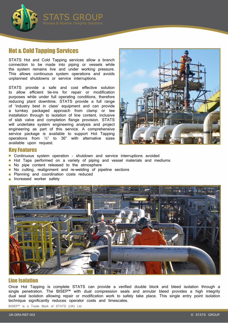
Hot & Cold Tapping Services
Key FeaturesContinuous system operation - shutdown and service interruptions avoidedHot Taps performed on a variety of piping and vessel materials and mediumsNo pipe content released to the atmosphereNo cutting, realignment and re-welding of pipeline sectionsPlanning and coordination costs reduced Increased worker safety
Once Hot Tapping is complete STATS can provide a verified double block and bleed isolation through a single penetration. The BISEP™ with dual compression seals and annular bleed provides a high integrity dual seal isolation allowing repair or modification work to safely take place. This single entry point isolation technique significantly reduces operator costs and timescales.
STATS Hot and Cold Tapping services allow a branch connection to be made into piping or vessels while the system remains live and under working pressure. This allows continuous system operations and avoids unplanned shutdowns or service interruptions.
STATS provide a safe and cost effective solution to allow efficient tie-ins for repair or modification purposes while under full operating conditions, therefore reducing plant downtime. STATS provide a full range of ‘industry best in class’ equipment and can provide a turnkey packaged approach from clamp or tee installation through to isolation of line content, inclusive of slab valve and completion flange provision. STATS will undertake system engineering analysis and project engineering as part of this service. A comprehensive service package is available to support Hot Tapping operations from ½” to 36” with alternative sizes available upon request.
Line Isolation
BISEP™ is a Trade Mark of STATS (UK) Ltd

STATS GROUPProcess & Pipeline Integrity Solutions
© STATS GROUPUK-GRA-REF-003
On-Site Machining ServicesIn hazardous environments where the potential for fire or explosion exists or when greater precision is desired, STATS Cold Cutting & bevelling service replaces traditional methods such as torches, reed cutters, and grinders. Fully preparing the pipe end for welding with greater accuracy and a higher level of safety, field cuts are performed quickly and effectively often without the requirement for hot work permits.
STATS offer portable clamshell lathes designed for on-site precision severing, severing / beveling, and severing / double beveling.
The aluminum frame is a split ring assembly capable of being disassembled to be installed around in-line piping. The frame has bearing mountings for the rotating head, a drive motor mount, locator pads for mounting to the pipe, and a gear cover. Our low clearance clamshells are designed to fit into tight working areas as well as minimise machine weight. These clamshells are lightweight, but retain rigidity during operation.
Key FeaturesSizes ranging from 4” up to 40”Counterbore ModuleCompressed Air or Hydraulic Drive In-Line or Right Angle DriveLocator Pads for Extended RangeReduced Axial Clearance with special tooling
These lathes simultaneously sever and bevel as they cut. Tool bits are automatically fed radially into the work piece with each rotation of the lathe, which assures precise machining. The machines can be fitted with single point beveling tool boxes for heavy wall pipe. The split frame design enables easy setup on in-line piping, elbows, tees, valves, nozzles and flanges.
STATS GROUPProcess & Pipeline Integrity Solutions
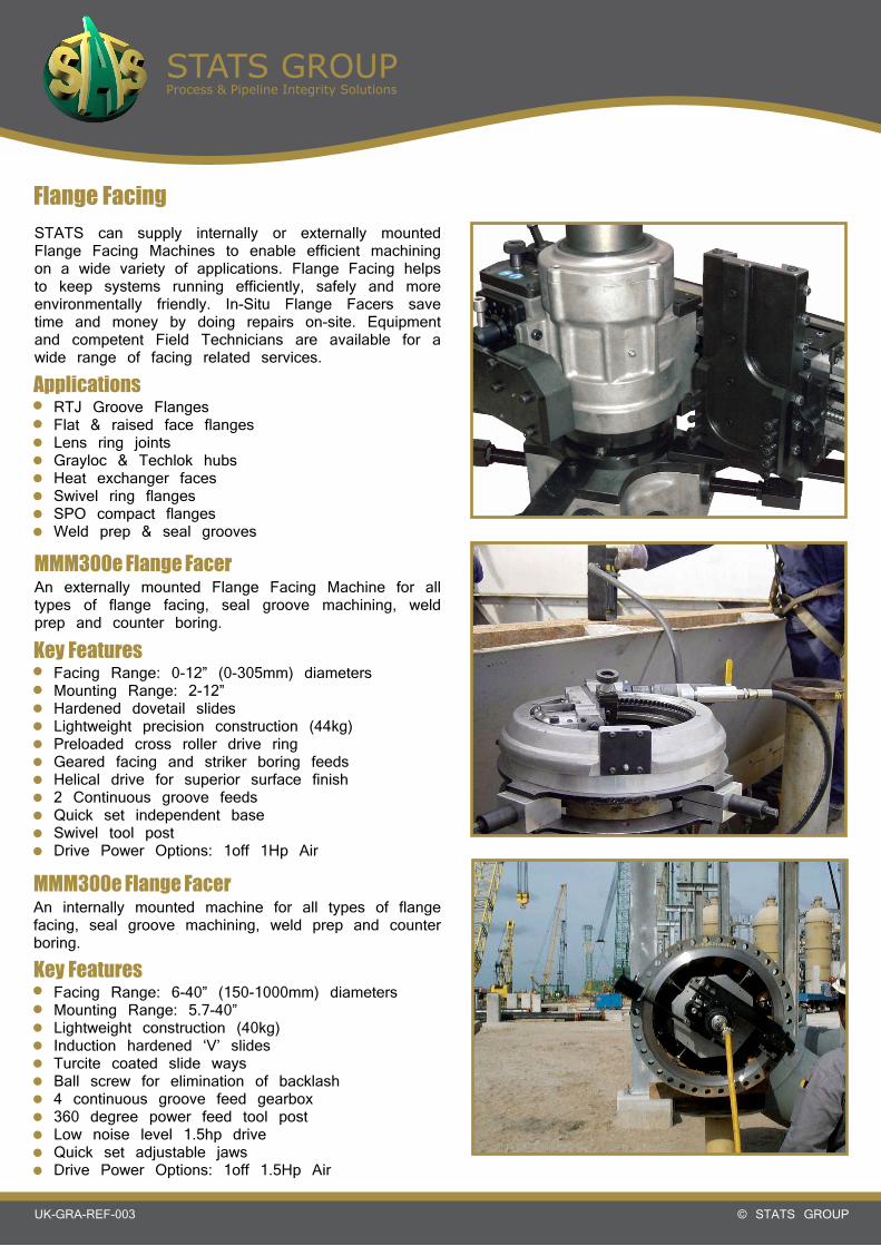
© STATS GROUPUK-GRA-REF-003
Flange FacingSTATS can supply internally or externally mounted Flange Facing Machines to enable efficient machining on a wide variety of applications. Flange Facing helps to keep systems running efficiently, safely and more environmentally friendly. In-Situ Flange Facers save time and money by doing repairs on-site. Equipment and competent Field Technicians are available for a wide range of facing related services.
ApplicationsRTJ Groove FlangesFlat & raised face flangesLens ring jointsGrayloc & Techlok hubsHeat exchanger facesSwivel ring flangesSPO compact flangesWeld prep & seal grooves
MMM300e Flange FacerAn externally mounted Flange Facing Machine for all types of flange facing, seal groove machining, weld prep and counter boring.
Key FeaturesFacing Range: 0-12” (0-305mm) diametersMounting Range: 2-12”Hardened dovetail slidesLightweight precision construction (44kg)Preloaded cross roller drive ringGeared facing and striker boring feedsHelical drive for superior surface finish2 Continuous groove feedsQuick set independent baseSwivel tool postDrive Power Options: 1off 1Hp Air
MMM300e Flange FacerAn internally mounted machine for all types of flange facing, seal groove machining, weld prep and counter boring.
Key FeaturesFacing Range: 6-40” (150-1000mm) diametersMounting Range: 5.7-40”Lightweight construction (40kg)Induction hardened ‘V’ slidesTurcite coated slide waysBall screw for elimination of backlash4 continuous groove feed gearbox360 degree power feed tool postLow noise level 1.5hp driveQuick set adjustable jawsDrive Power Options: 1off 1.5Hp Air