isolating interface units - mtl instruments · isolating interface units january 2017 inm 4500/4600...
TRANSCRIPT

MTL4500/4600 rangeIsolating interface units
January 2017INM 4500/4600 Rev 11
Instruction manualMTL intrinsic safety solutions

INM 4500/4600 Rev 11ii
DECLARATION OF CONFORMITY
A printed version of the Declaration of Conformity has been provided separately within the original shipment of goods. However, you can find a copy of the latest version at: http://www.mtl-inst.com/certificates
INM 4500/4600 Rev 11 iii
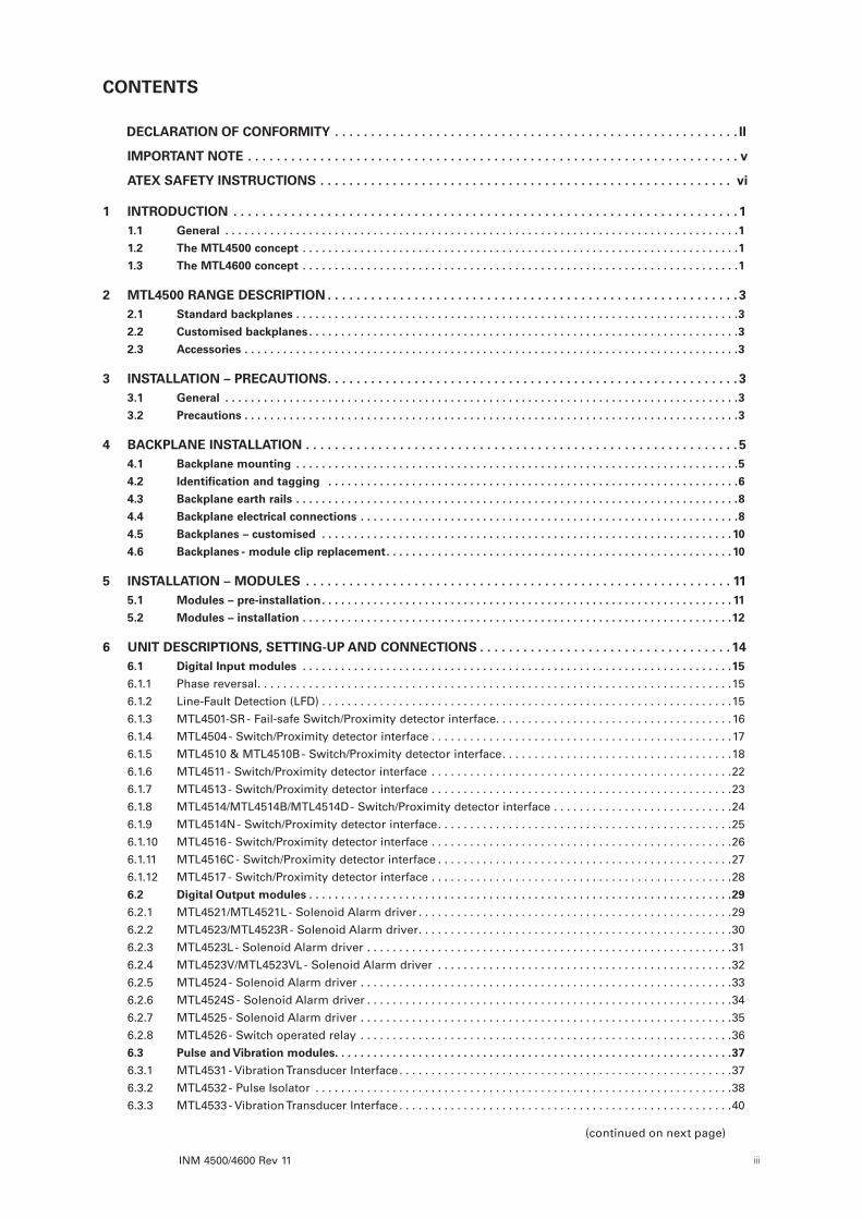
CONTENTS
DECLARATION OF CONFORMITY . . . . . . . . . . . . . . . . . . . . . . . . . . . . . . . . . . . . . . . . . . . . . . . . . . . . . . . . II
IMPORTANT NOTE . . . . . . . . . . . . . . . . . . . . . . . . . . . . . . . . . . . . . . . . . . . . . . . . . . . . . . . . . . . . . . . . . . . . v
ATEX SAFETY INSTRUCTIONS . . . . . . . . . . . . . . . . . . . . . . . . . . . . . . . . . . . . . . . . . . . . . . . . . . . . . . . . . vi
1 INTRODUCTION . . . . . . . . . . . . . . . . . . . . . . . . . . . . . . . . . . . . . . . . . . . . . . . . . . . . . . . . . . . . . . . . . . . . . . 11 .1 General . . . . . . . . . . . . . . . . . . . . . . . . . . . . . . . . . . . . . . . . . . . . . . . . . . . . . . . . . . . . . . . . . . . . . . . . . . . . . . . .1
1 .2 The MTL4500 concept . . . . . . . . . . . . . . . . . . . . . . . . . . . . . . . . . . . . . . . . . . . . . . . . . . . . . . . . . . . . . . . . . . . .1
1 .3 The MTL4600 concept . . . . . . . . . . . . . . . . . . . . . . . . . . . . . . . . . . . . . . . . . . . . . . . . . . . . . . . . . . . . . . . . . . . .1
2 MTL4500 RANGE DESCRIPTION . . . . . . . . . . . . . . . . . . . . . . . . . . . . . . . . . . . . . . . . . . . . . . . . . . . . . . . . . 32 .1 Standard backplanes . . . . . . . . . . . . . . . . . . . . . . . . . . . . . . . . . . . . . . . . . . . . . . . . . . . . . . . . . . . . . . . . . . . . .3
2 .2 Customised backplanes . . . . . . . . . . . . . . . . . . . . . . . . . . . . . . . . . . . . . . . . . . . . . . . . . . . . . . . . . . . . . . . . . . .3
2 .3 Accessories . . . . . . . . . . . . . . . . . . . . . . . . . . . . . . . . . . . . . . . . . . . . . . . . . . . . . . . . . . . . . . . . . . . . . . . . . . . . .3
3 INSTALLATION – PRECAUTIONS . . . . . . . . . . . . . . . . . . . . . . . . . . . . . . . . . . . . . . . . . . . . . . . . . . . . . . . . . 33 .1 General . . . . . . . . . . . . . . . . . . . . . . . . . . . . . . . . . . . . . . . . . . . . . . . . . . . . . . . . . . . . . . . . . . . . . . . . . . . . . . . .3
3 .2 Precautions . . . . . . . . . . . . . . . . . . . . . . . . . . . . . . . . . . . . . . . . . . . . . . . . . . . . . . . . . . . . . . . . . . . . . . . . . . . . .3
4 BACKPLANE INSTALLATION . . . . . . . . . . . . . . . . . . . . . . . . . . . . . . . . . . . . . . . . . . . . . . . . . . . . . . . . . . . . 54 .1 Backplane mounting . . . . . . . . . . . . . . . . . . . . . . . . . . . . . . . . . . . . . . . . . . . . . . . . . . . . . . . . . . . . . . . . . . . . .5
4 .2 Identification and tagging . . . . . . . . . . . . . . . . . . . . . . . . . . . . . . . . . . . . . . . . . . . . . . . . . . . . . . . . . . . . . . . .6
4 .3 Backplane earth rails . . . . . . . . . . . . . . . . . . . . . . . . . . . . . . . . . . . . . . . . . . . . . . . . . . . . . . . . . . . . . . . . . . . . .8
4 .4 Backplane electrical connections . . . . . . . . . . . . . . . . . . . . . . . . . . . . . . . . . . . . . . . . . . . . . . . . . . . . . . . . . . .8
4 .5 Backplanes – customised . . . . . . . . . . . . . . . . . . . . . . . . . . . . . . . . . . . . . . . . . . . . . . . . . . . . . . . . . . . . . . . .10
4 .6 Backplanes - module clip replacement . . . . . . . . . . . . . . . . . . . . . . . . . . . . . . . . . . . . . . . . . . . . . . . . . . . . . .10
5 INSTALLATION – MODULES . . . . . . . . . . . . . . . . . . . . . . . . . . . . . . . . . . . . . . . . . . . . . . . . . . . . . . . . . . . 115 .1 Modules – pre-installation . . . . . . . . . . . . . . . . . . . . . . . . . . . . . . . . . . . . . . . . . . . . . . . . . . . . . . . . . . . . . . . . 11
5 .2 Modules – installation . . . . . . . . . . . . . . . . . . . . . . . . . . . . . . . . . . . . . . . . . . . . . . . . . . . . . . . . . . . . . . . . . . .12
6 UNIT DESCRIPTIONS, SETTING-UP AND CONNECTIONS . . . . . . . . . . . . . . . . . . . . . . . . . . . . . . . . . . . 146 .1 Digital Input modules . . . . . . . . . . . . . . . . . . . . . . . . . . . . . . . . . . . . . . . . . . . . . . . . . . . . . . . . . . . . . . . . . . .15
6.1.1 Phase reversal . . . . . . . . . . . . . . . . . . . . . . . . . . . . . . . . . . . . . . . . . . . . . . . . . . . . . . . . . . . . . . . . . . . . . . . . . .15
6.1.2 Line-Fault Detection (LFD) . . . . . . . . . . . . . . . . . . . . . . . . . . . . . . . . . . . . . . . . . . . . . . . . . . . . . . . . . . . . . . . .15
6.1.3 MTL4501-SR - Fail-safe Switch/Proximity detector interface . . . . . . . . . . . . . . . . . . . . . . . . . . . . . . . . . . . . .16
6.1.4 MTL4504 - Switch/Proximity detector interface . . . . . . . . . . . . . . . . . . . . . . . . . . . . . . . . . . . . . . . . . . . . . . .17
6.1.5 MTL4510 & MTL4510B - Switch/Proximity detector interface . . . . . . . . . . . . . . . . . . . . . . . . . . . . . . . . . . . .18
6.1.6 MTL4511 - Switch/Proximity detector interface . . . . . . . . . . . . . . . . . . . . . . . . . . . . . . . . . . . . . . . . . . . . . . .22
6.1.7 MTL4513 - Switch/Proximity detector interface . . . . . . . . . . . . . . . . . . . . . . . . . . . . . . . . . . . . . . . . . . . . . . .23
6.1.8 MTL4514/MTL4514B/MTL4514D - Switch/Proximity detector interface . . . . . . . . . . . . . . . . . . . . . . . . . . . .24
6.1.9 MTL4514N - Switch/Proximity detector interface . . . . . . . . . . . . . . . . . . . . . . . . . . . . . . . . . . . . . . . . . . . . . .25
6.1.10 MTL4516 - Switch/Proximity detector interface . . . . . . . . . . . . . . . . . . . . . . . . . . . . . . . . . . . . . . . . . . . . . . .26
6.1.11 MTL4516C - Switch/Proximity detector interface . . . . . . . . . . . . . . . . . . . . . . . . . . . . . . . . . . . . . . . . . . . . . .27
6.1.12 MTL4517 - Switch/Proximity detector interface . . . . . . . . . . . . . . . . . . . . . . . . . . . . . . . . . . . . . . . . . . . . . . .28
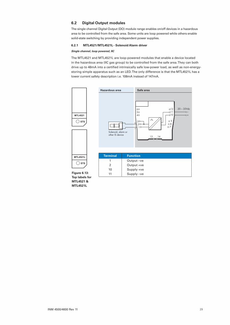
6 .2 Digital Output modules . . . . . . . . . . . . . . . . . . . . . . . . . . . . . . . . . . . . . . . . . . . . . . . . . . . . . . . . . . . . . . . . . .29
6.2.1 MTL4521/MTL4521L - Solenoid Alarm driver . . . . . . . . . . . . . . . . . . . . . . . . . . . . . . . . . . . . . . . . . . . . . . . . .29
6.2.2 MTL4523/MTL4523R - Solenoid Alarm driver . . . . . . . . . . . . . . . . . . . . . . . . . . . . . . . . . . . . . . . . . . . . . . . . .30
6.2.3 MTL4523L - Solenoid Alarm driver . . . . . . . . . . . . . . . . . . . . . . . . . . . . . . . . . . . . . . . . . . . . . . . . . . . . . . . . .31
6.2.4 MTL4523V/MTL4523VL - Solenoid Alarm driver . . . . . . . . . . . . . . . . . . . . . . . . . . . . . . . . . . . . . . . . . . . . . .32
6.2.5 MTL4524 - Solenoid Alarm driver . . . . . . . . . . . . . . . . . . . . . . . . . . . . . . . . . . . . . . . . . . . . . . . . . . . . . . . . . .33
6.2.6 MTL4524S - Solenoid Alarm driver . . . . . . . . . . . . . . . . . . . . . . . . . . . . . . . . . . . . . . . . . . . . . . . . . . . . . . . . .34
6.2.7 MTL4525 - Solenoid Alarm driver . . . . . . . . . . . . . . . . . . . . . . . . . . . . . . . . . . . . . . . . . . . . . . . . . . . . . . . . . .35
6.2.8 MTL4526 - Switch operated relay . . . . . . . . . . . . . . . . . . . . . . . . . . . . . . . . . . . . . . . . . . . . . . . . . . . . . . . . . .36
6 .3 Pulse and Vibration modules . . . . . . . . . . . . . . . . . . . . . . . . . . . . . . . . . . . . . . . . . . . . . . . . . . . . . . . . . . . . . .37
6.3.1 MTL4531 - Vibration Transducer Interface . . . . . . . . . . . . . . . . . . . . . . . . . . . . . . . . . . . . . . . . . . . . . . . . . . . .37
6.3.2 MTL4532 - Pulse Isolator . . . . . . . . . . . . . . . . . . . . . . . . . . . . . . . . . . . . . . . . . . . . . . . . . . . . . . . . . . . . . . . . .38
6.3.3 MTL4533 - Vibration Transducer Interface . . . . . . . . . . . . . . . . . . . . . . . . . . . . . . . . . . . . . . . . . . . . . . . . . . . .40
(continued on next page)

INM 4500/4600 Rev 11iv
6 .4 Analogue Input modules . . . . . . . . . . . . . . . . . . . . . . . . . . . . . . . . . . . . . . . . . . . . . . . . . . . . . . . . . . . . . . . . .41
6.4.1 MTL4541/MTL4541S/MTL4541Y - Repeater Power Supply . . . . . . . . . . . . . . . . . . . . . . . . . . . . . . . . . . . . . .41
6.4.2 MTL4541A/MTL4541AS/MTL4541YA - Current Repeater . . . . . . . . . . . . . . . . . . . . . . . . . . . . . . . . . . . . . . .42
6.4.3 MTL4541B/MTL4541P/MTL4541T - Repeater Power Supply . . . . . . . . . . . . . . . . . . . . . . . . . . . . . . . . . . . . .43
6.4.4 MTL4544/MTL4544S - Repeater Power Supply . . . . . . . . . . . . . . . . . . . . . . . . . . . . . . . . . . . . . . . . . . . . . . .44
6.4.5 MTL4544A/MTL4544AS - Current Repeater . . . . . . . . . . . . . . . . . . . . . . . . . . . . . . . . . . . . . . . . . . . . . . . . . .45
6.4.6 MTL4544B - Repeater Power Supply . . . . . . . . . . . . . . . . . . . . . . . . . . . . . . . . . . . . . . . . . . . . . . . . . . . . . . . .46
6.4.7 MTL4544D - Repeater Power Supply . . . . . . . . . . . . . . . . . . . . . . . . . . . . . . . . . . . . . . . . . . . . . . . . . . . . . . . .47
6 .5 Analogue Output modules . . . . . . . . . . . . . . . . . . . . . . . . . . . . . . . . . . . . . . . . . . . . . . . . . . . . . . . . . . . . . . .48
6.5.1 MTL4545Y/MTL4546/MTL4546C/MTL4546S/MTL4546Y - Isolating Driver . . . . . . . . . . . . . . . . . . . . . . . . . .48
6.5.2 MTL4549/MTL4549C/MTL4549Y - Isolating Driver . . . . . . . . . . . . . . . . . . . . . . . . . . . . . . . . . . . . . . . . . . . . .49
6 .6 Fire and Smoke Interface modules . . . . . . . . . . . . . . . . . . . . . . . . . . . . . . . . . . . . . . . . . . . . . . . . . . . . . . . . .50
6.6.1 MTL4561 - Fire and Smoke Detector Interface . . . . . . . . . . . . . . . . . . . . . . . . . . . . . . . . . . . . . . . . . . . . . . . .50
6 .7 Temperature Input module . . . . . . . . . . . . . . . . . . . . . . . . . . . . . . . . . . . . . . . . . . . . . . . . . . . . . . . . . . . . . . .51
6.7.1 MTL4573 - Temperature Converter . . . . . . . . . . . . . . . . . . . . . . . . . . . . . . . . . . . . . . . . . . . . . . . . . . . . . . . . . .52
6.7.2 MTL4575 - Temperature Converter . . . . . . . . . . . . . . . . . . . . . . . . . . . . . . . . . . . . . . . . . . . . . . . . . . . . . . . . . .53
6.7.3 MTL4576-RTD - Temperature Converter . . . . . . . . . . . . . . . . . . . . . . . . . . . . . . . . . . . . . . . . . . . . . . . . . . . . .54
6.7.4 MTL4576-THC - Temperature Converter . . . . . . . . . . . . . . . . . . . . . . . . . . . . . . . . . . . . . . . . . . . . . . . . . . . . .55
6.7.5 MTL4581 - mV/Thermocouple Isolator . . . . . . . . . . . . . . . . . . . . . . . . . . . . . . . . . . . . . . . . . . . . . . . . . . . . . .56
6 .8 General modules . . . . . . . . . . . . . . . . . . . . . . . . . . . . . . . . . . . . . . . . . . . . . . . . . . . . . . . . . . . . . . . . . . . . . . .57
6.8.1 MTL4599 - Dummy Isolator . . . . . . . . . . . . . . . . . . . . . . . . . . . . . . . . . . . . . . . . . . . . . . . . . . . . . . . . . . . . . . .57
6.8.2 MTL4599N - General purpose feedthrough module . . . . . . . . . . . . . . . . . . . . . . . . . . . . . . . . . . . . . . . . . . .57
6 .9 PCS45/PCL45USB configurator for MTL temperature converters . . . . . . . . . . . . . . . . . . . . . . . . . . . . . . . .58
7 FAULT FINDING AND ROUTINE MAINTENANCE . . . . . . . . . . . . . . . . . . . . . . . . . . . . . . . . . . . . . . . . . . . 597 .1 Maintenance precautions . . . . . . . . . . . . . . . . . . . . . . . . . . . . . . . . . . . . . . . . . . . . . . . . . . . . . . . . . . . . . . . .59
7 .2 Fault finding . . . . . . . . . . . . . . . . . . . . . . . . . . . . . . . . . . . . . . . . . . . . . . . . . . . . . . . . . . . . . . . . . . . . . . . . . . .59
7 .3 Routine maintenance . . . . . . . . . . . . . . . . . . . . . . . . . . . . . . . . . . . . . . . . . . . . . . . . . . . . . . . . . . . . . . . . . . . .59
8 BENCH TESTING MODULES . . . . . . . . . . . . . . . . . . . . . . . . . . . . . . . . . . . . . . . . . . . . . . . . . . . . . . . . . . . 618 .1 Digital Input (DI) modules . . . . . . . . . . . . . . . . . . . . . . . . . . . . . . . . . . . . . . . . . . . . . . . . . . . . . . . . . . . . . . . .61
8 .2 Digital Output (DO) modules . . . . . . . . . . . . . . . . . . . . . . . . . . . . . . . . . . . . . . . . . . . . . . . . . . . . . . . . . . . . . .62
8 .3 Analogue Input (AI) Modules . . . . . . . . . . . . . . . . . . . . . . . . . . . . . . . . . . . . . . . . . . . . . . . . . . . . . . . . . . . . .63
8 .4 Analogue Output (AO) Modules . . . . . . . . . . . . . . . . . . . . . . . . . . . . . . . . . . . . . . . . . . . . . . . . . . . . . . . . . . .65
8 .5 Testing the functioning of other modules . . . . . . . . . . . . . . . . . . . . . . . . . . . . . . . . . . . . . . . . . . . . . . . . . . .65
9 APPLICATIONS INVOLVING ZONE 2 AND/OR ZONE 22 HAZARDOUS AREAS . . . . . . . . . . . . . . . . . . 669 .1 Enclosure . . . . . . . . . . . . . . . . . . . . . . . . . . . . . . . . . . . . . . . . . . . . . . . . . . . . . . . . . . . . . . . . . . . . . . . . . . . . . .66
10 APPENDIX . . . . . . . . . . . . . . . . . . . . . . . . . . . . . . . . . . . . . . . . . . . . . . . . . . . . . . . . . . . . . . . . . . . . . . . . . . 6710 .1 Table A - Safety descriptions . . . . . . . . . . . . . . . . . . . . . . . . . . . . . . . . . . . . . . . . . . . . . . . . . . . . . . . . . . . . . .67
10 .2 Table B - Maximum cable parameters - IIC gas group . . . . . . . . . . . . . . . . . . . . . . . . . . . . . . . . . . . . . . . . .67
© 2017 Eaton Electric Limited. All rights reserved.
INM 4500/4600 Rev 11 v
IMPORTANT NOTE
This manual describes the installation and use of:
• MTL4500 range of isolating interfaces for Intrinsic Safety
• MTL4600 range of signal conditioners
The MTL4500 range of products are intended for protection of hazardous areas in process
plants that apply Intrinsic Safety techniques.
Although functionally similar to the MTL4500 range, the MTL4600 range of isolator modules are NOT certified or approved for connection to hazardous area circuits.
To ensure both the segregation of equipment and the requisite separation of wiring, operation and maintenance activities, it is recommended that the MTL4500 and the MTL4600 range of modules are NOT mounted on the same backplane.
The use of separate backplanes for I.S. and non-I.S. signals reduces the possibility of confusion over ‘safe operating practice’ and is strongly recommended.
MTL4500 range of products
WARNING !This manual has content describing the use and installation of safety
equipment. This equipment must be installed, operated and maintained only by trained competent personnel and in accordance with all
appropriate international, national and local standard codes of practice and site regulations for intrinsically safe apparatus and in accordance
with the instructions contained here.
ATEX
If the country of installation is governed by the Essential Health and Safety Requirements (Annex II) of the EU Directive 2014/34/EU [the ATEX Directive - safety of apparatus] then consult the ATEX safety instructions for safe use in this manual before installation.
Note: Refer to the website for multiple language safety instructions.
ELECTRICAL PARAMETERS
Refer to the certification documentation for the electrical rating of these products.
CERTIFICATION DOCUMENTATION
Our website http://www.mtl-inst.com contains product documentation regarding intrinsic safety certification for many locations around the world. Consult this data for information relevant to your local certifying authority.
FUNCTIONAL SAFETY
If the MTL4500 range of products are to be used in functional safety applications check that each module has been asssessed for that service and refer to the Safety Manual for details.
REPAIR
MTL4500 range of products MUST NOT be repaired. Faulty or damaged products must be replaced with an equivalent certified product.
CLEANING
Should modules require cleaning, use water only on a damp cloth.
Symbols used on the product and in this manual
CAUTION - Read the instructions
CAUTION - Hot surface
INM 4500/4600 Rev 11vi
ATEX SAFETY INSTRUCTIONS The following information is in accordance with the Essential Health and Safety Requirements (Annex II) of the EU Directive 2014/34/EU [the ATEX Directive - safety of apparatus] and is provided for those locations where the ATEX Directive is applicable.
General
a) This equipment must only be installed, operated and maintained by competent personnel. Such personnel shall have undergone training, which included instruction on the various types of protection and installation practices, the relevant rules and regulations, and on the general principles of area classification. Appropriate refresher training shall be given on a regular basis. [See clause 4.2 of EN 60079-17].
b) This equipment has been designed to provide protection against all the relevant additional hazards referred to in Annex II of the directive, such as those in clause 1.2.7.
c) This equipment has been designed to meet the requirements of EN 60079-15.
Installation
a) The installation must comply with the appropriate European, national and local regulations, which may include reference to the IEC code of practice IEC 60079-14. In addition, particular industries or end users may have specific requirements relating to the safety of their installations and these requirements should also be met. For the majority of installations the Directive 1999/92/EC [the ATEX Directive - safety of installations] is also applicable.
b) This apparatus is an associated electrical apparatus and is normally mounted in a non-hazardous [safe] area. Specific apparatus described as Category 3 compliant may be installed in a Zone 2 location providing that the relevant installation conditions are met. When mounted in a Zone 2 location the apparatus must be provided with an enclosure, which offers an additional degree of protection appropriate to the area classification.
c) Unless already protected by design, this equipment must be protected by a suitable enclosure against: i) mechanical and thermal stresses in excess of those noted in the certification documentation and the product specification
ii) aggressive substances, excessive dust, moisture and other contaminants.
Read also the Special Conditions for Safe Use (below) for any additional or more specific information.
Special Conditions of Safe Use for Zone 2 applications
a) When used in Zone 2, the equipment must be installed in an enclosure or an environment that provides a degree of protection of at least IP54 and meets the relevant material and environmental requirements of EN 60079-0:2012 and EN 60079-15:2010.
b) The equipment must not be inserted or removed unless either:
i) the area in which the equipment is installed is known to be non-hazardous or
ii) the circuit to which it is connected has been de-energised.
c) The 24V supply for this equipment must be derived from a regulated power supply complying with the requirements of European Community Directives.
d) For 4511, 4514, 4514B, 4514D, 4516, 4516C, 4517, 4526 & 4532 only: Relay contacts may switch up to 35V, 0.5A and 10W.
For 4575: Relay contacts may switch up to 35V, 250mA.
e) Any backplane used does not form part of this certificate and shall be separately certified for use in Zone 2.
f) The associated backplane must be fitted with MTL4500 retention clips (use type MCK45 if not fitted) that allow the equipment to be ‘clipped’ to the backplane. The retention clips shall always be in place when the equipment is energised.
g) For 4573 Maximum Input/Output parameters – see certificate
INM 4500/4600 Rev 11 vii
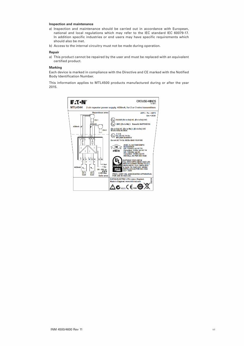
Inspection and maintenancea) Inspection and maintenance should be carried out in accordance with European,
national and local regulations which may refer to the IEC standard IEC 60079-17. In addition specific industries or end users may have specific requirements which should also be met.
b) Access to the internal circuitry must not be made during operation.
Repair a) This product cannot be repaired by the user and must be replaced with an equivalent
certified product.
MarkingEach device is marked in compliance with the Directive and CE marked with the Notified Body Identification Number.
This information applies to MTL4500 products manufactured during or after the year 2015.

INM 4500/4600 Rev 11viii
This page left intentionally blank
INM 4500/4600 Rev 11 1
1 INTRODUCTION
1 .1 GeneralThis instruction manual describes the procedures for installing, connecting, checking and maintaining MTL4500/4600 range of isolating interfaces and accessories. The MTL4500 products provide an intrinsically safe (IS) interface to a hazardous area of a process plant, while the MTL4600 range is exclusively for non-hazardous area service.
The individual sections cover the following topics
• Section 2 describes the range and its accessories
• Section 3 specifies precautions before installation
• Section 4 covers the installation of backplanes
• Section 5 describes the installation of modules onto the backplanes
• Section 6 provides relevant technical data
• Section 7 outlines fault-finding and maintenance
• Section 8 describes bench test procedures
• Section 9 provides hazardous-area application information
• Section 10 provides safety parameter information
1 .2 The MTL4500 conceptThe MTL4500 range of modules and accessories are designed for use with process connected systems. It consists of compact isolating interface modules mounted on backplanes, which carry safe-area signals and power supplies. Hazardous-area circuits connect to the blue terminals on the modules. Backplanes can be integrated into a user’s process system architecture or mounted in separate enclosures.
1 .3 The MTL4600 conceptThe MTL4600 range of modules and accessories are designed for use with process connected systems, but in non-hazardous area applications. They are based on the MTL4500 range but have been given a separate identity to avoid the burden of administration previously associated with the use of IS modules in non-IS applications. Field equipment, located in non-hazardous areas, connects to the grey terminals on the modules.
Most of the mechanical and electrical characteristics shared by the two ranges are identical. The information contained in this manual relates specifically to the MTL4500 range of products; however, where an MTL4600 version of the module exists, the information is also applicable unless otherwise specified.
INM 4500/4600 Rev 112
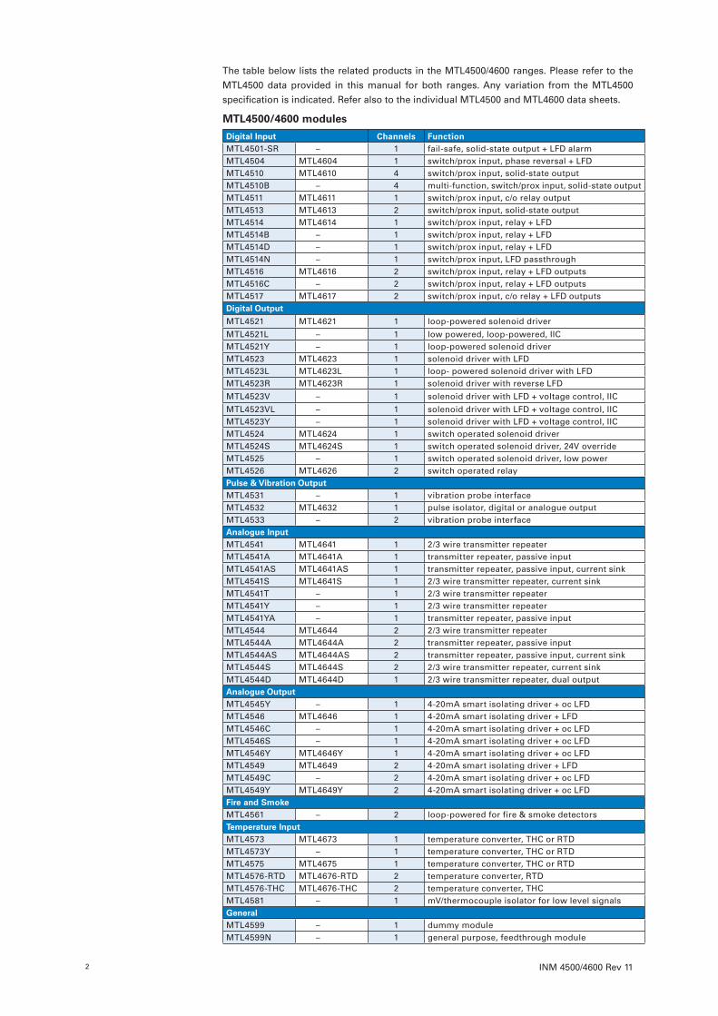
The table below lists the related products in the MTL4500/4600 ranges. Please refer to the MTL4500 data provided in this manual for both ranges. Any variation from the MTL4500 specification is indicated. Refer also to the individual MTL4500 and MTL4600 data sheets.
MTL4500/4600 modules
Digital Input Channels FunctionMTL4501-SR – 1 fail-safe, solid-state output + LFD alarmMTL4504 MTL4604 1 switch/prox input, phase reversal + LFDMTL4510 MTL4610 4 switch/prox input, solid-state outputMTL4510B – 4 multi-function, switch/prox input, solid-state outputMTL4511 MTL4611 1 switch/prox input, c/o relay outputMTL4513 MTL4613 2 switch/prox input, solid-state outputMTL4514 MTL4614 1 switch/prox input, relay + LFDMTL4514B – 1 switch/prox input, relay + LFDMTL4514D – 1 switch/prox input, relay + LFDMTL4514N – 1 switch/prox input, LFD passthroughMTL4516 MTL4616 2 switch/prox input, relay + LFD outputs MTL4516C – 2 switch/prox input, relay + LFD outputsMTL4517 MTL4617 2 switch/prox input, c/o relay + LFD outputsDigital Output
MTL4521 MTL4621 1 loop-powered solenoid driver
MTL4521L – 1 low powered, loop-powered, IICMTL4521Y – 1 loop-powered solenoid driverMTL4523 MTL4623 1 solenoid driver with LFDMTL4523L MTL4623L 1 loop- powered solenoid driver with LFDMTL4523R MTL4623R 1 solenoid driver with reverse LFD
MTL4523V – 1 solenoid driver with LFD + voltage control, IIC
MTL4523VL – 1 solenoid driver with LFD + voltage control, IICMTL4523Y – 1 solenoid driver with LFD + voltage control, IICMTL4524 MTL4624 1 switch operated solenoid driverMTL4524S MTL4624S 1 switch operated solenoid driver, 24V overrideMTL4525 – 1 switch operated solenoid driver, low powerMTL4526 MTL4626 2 switch operated relayPulse & Vibration OutputMTL4531 – 1 vibration probe interfaceMTL4532 MTL4632 1 pulse isolator, digital or analogue outputMTL4533 – 2 vibration probe interfaceAnalogue InputMTL4541 MTL4641 1 2/3 wire transmitter repeaterMTL4541A MTL4641A 1 transmitter repeater, passive inputMTL4541AS MTL4641AS 1 transmitter repeater, passive input, current sinkMTL4541S MTL4641S 1 2/3 wire transmitter repeater, current sinkMTL4541T – 1 2/3 wire transmitter repeaterMTL4541Y – 1 2/3 wire transmitter repeaterMTL4541YA – 1 transmitter repeater, passive inputMTL4544 MTL4644 2 2/3 wire transmitter repeaterMTL4544A MTL4644A 2 transmitter repeater, passive inputMTL4544AS MTL4644AS 2 transmitter repeater, passive input, current sinkMTL4544S MTL4644S 2 2/3 wire transmitter repeater, current sinkMTL4544D MTL4644D 1 2/3 wire transmitter repeater, dual outputAnalogue OutputMTL4545Y – 1 4-20mA smart isolating driver + oc LFDMTL4546 MTL4646 1 4-20mA smart isolating driver + LFDMTL4546C – 1 4-20mA smart isolating driver + oc LFDMTL4546S – 1 4-20mA smart isolating driver + oc LFDMTL4546Y MTL4646Y 1 4-20mA smart isolating driver + oc LFDMTL4549 MTL4649 2 4-20mA smart isolating driver + LFDMTL4549C – 2 4-20mA smart isolating driver + oc LFDMTL4549Y MTL4649Y 2 4-20mA smart isolating driver + oc LFDFire and SmokeMTL4561 – 2 loop-powered for fire & smoke detectorsTemperature InputMTL4573 MTL4673 1 temperature converter, THC or RTDMTL4573Y – 1 temperature converter, THC or RTDMTL4575 MTL4675 1 temperature converter, THC or RTDMTL4576-RTD MTL4676-RTD 2 temperature converter, RTDMTL4576-THC MTL4676-THC 2 temperature converter, THCMTL4581 – 1 mV/thermocouple isolator for low level signalsGeneralMTL4599 – 1 dummy moduleMTL4599N – 1 general purpose, feedthrough module
INM 4500/4600 Rev 11 3
2 MTL4500 RANGE DESCRIPTIONEach module has a multi-pin connector in its base that plugs into a matching connector on the backplane. This connector carries all appropriate safe-area circuits and power supplies. Additional multiway connectors, located at the front of the module, accept the wiring from the hazardous-area circuits. All connectors are keyed so that connections cannot be made the ‘wrong way round’.
Status LEDs and configuration ports (where appropriate) are located on the front of the modules for easy access, and full dc isolation is provided between the input and output so that the modules are intrinsically safe without needing an earth.
2 .1 Standard backplanesMTL4500 range of standard backplanes, with quick-release clip connectors, accommodate 4, 8, 16 or 24 modules. The backplane carries the safe-area signals and distributes dual-redundant 24V dc power supplies with three-point status monitoring. In applications where a number of 8- and 16-way backplanes are installed, the power supplies can be interconnected. Optional earth-rail kits are available for 8- and 16-way backplanes and tagging-strip kits are available for all backplanes.
2 .2 Customised backplanesIf the backplane is to be mounted in a safe area (which is the most common type of application) then it does not need to be certified, because the hazardous area wiring connects to the I/O modules, not the backplane. This means that non-hazardous area backplanes can be produced easily by Eaton, or the user, and can be designed to match exactly the size, shape, method of mounting, type of connector, pin assignments, etc, of a particular process system. Please contact Eaton’s MTL product line for further information.
When mounting the backplane in Zone 2/Div 2 hazardous areas refer to our website for documents detailing any approvals.
2 .3 AccessoriesAccessories are available that enable the user to mount standard MTL backplanes. These include surface-mounting kits, T-section and G-section DIN-rail mounting kits and end stops and a horizontal plate for mounting 24-way backplanes in 19-inch racks.
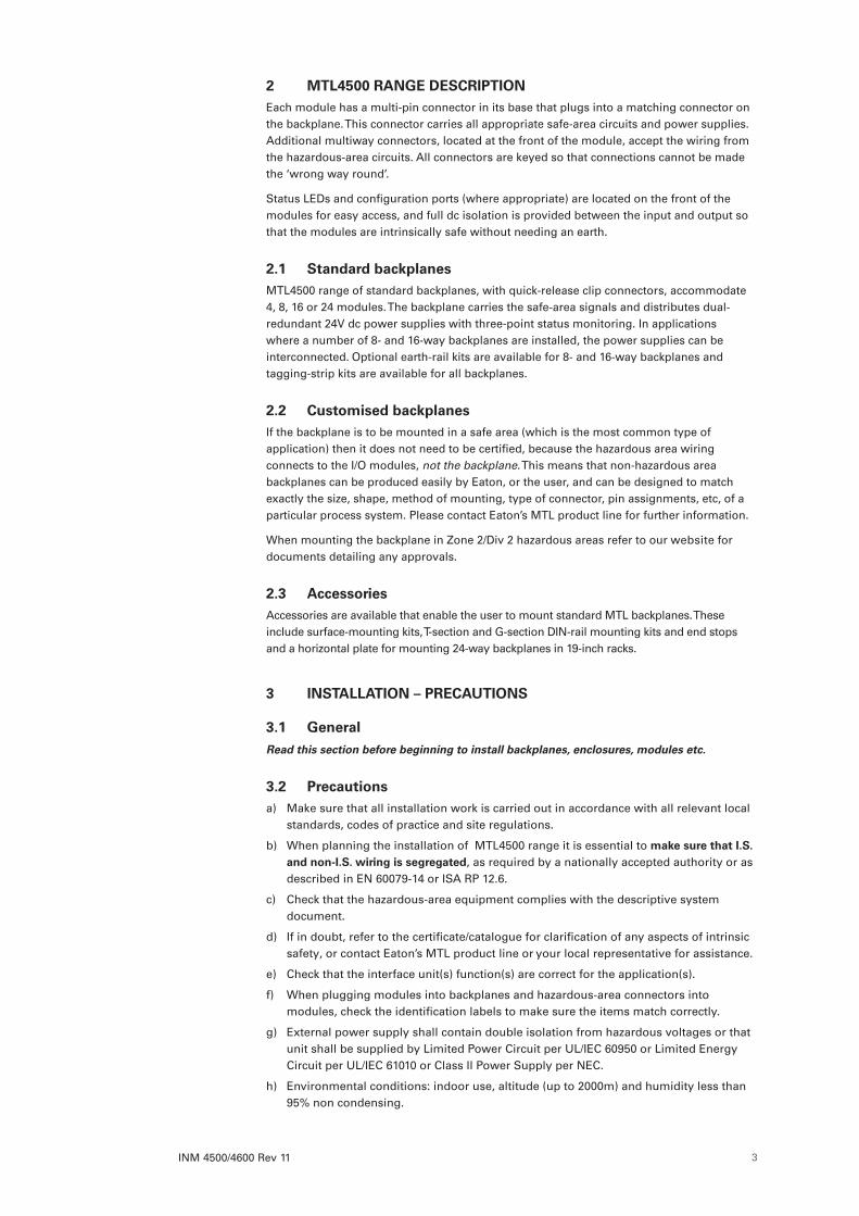
3 INSTALLATION – PRECAUTIONS
3 .1 GeneralRead this section before beginning to install backplanes, enclosures, modules etc.
3 .2 Precautionsa) Make sure that all installation work is carried out in accordance with all relevant local
standards, codes of practice and site regulations.
b) When planning the installation of MTL4500 range it is essential to make sure that I .S . and non-I .S . wiring is segregated, as required by a nationally accepted authority or as described in EN 60079-14 or ISA RP 12.6.
c) Check that the hazardous-area equipment complies with the descriptive system document.
d) If in doubt, refer to the certificate/catalogue for clarification of any aspects of intrinsic safety, or contact Eaton’s MTL product line or your local representative for assistance.
e) Check that the interface unit(s) function(s) are correct for the application(s).
f) When plugging modules into backplanes and hazardous-area connectors into modules, check the identification labels to make sure the items match correctly.
g) External power supply shall contain double isolation from hazardous voltages or that unit shall be supplied by Limited Power Circuit per UL/IEC 60950 or Limited Energy Circuit per UL/IEC 61010 or Class ll Power Supply per NEC.
h) Environmental conditions: indoor use, altitude (up to 2000m) and humidity less than 95% non condensing.
INM 4500/4600 Rev 114
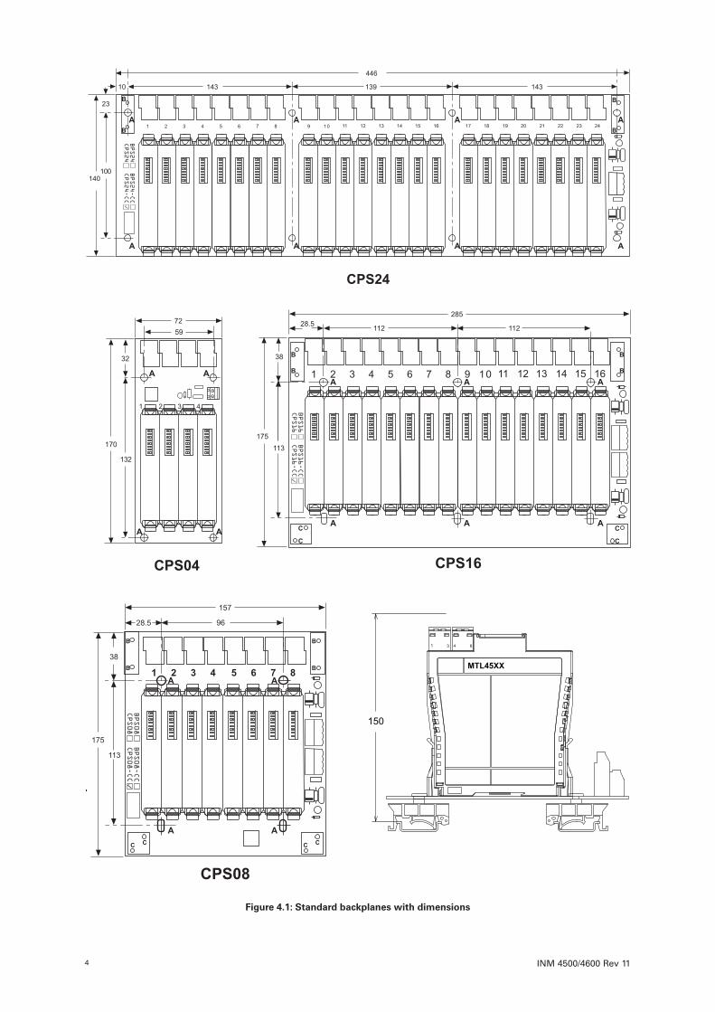
Figure 4 .1: Standard backplanes with dimensions
150
1 3 4 6
MTL45XX
INM 4500/4600 Rev 11 5
4 BACKPLANE INSTALLATION
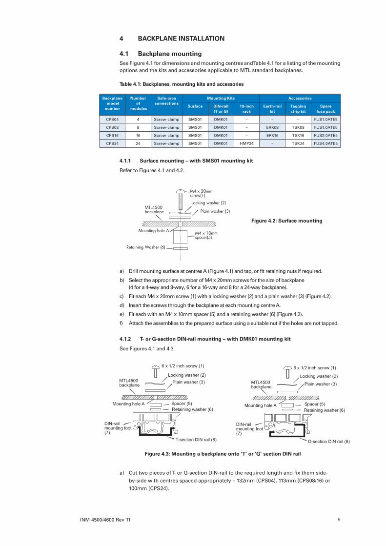
4 .1 Backplane mounting See Figure 4.1 for dimensions and mounting centres and Table 4.1 for a listing of the mounting options and the kits and accessories applicable to MTL standard backplanes.
Table 4 .1: Backplanes, mounting kits and accessories
Backplane model number
Number of
modules
Safe-area connections
Mounting Kits Accessories
Surface DIN-rail (T or G)
19-inch rack
Earth-rail kit
Tagging strip kit
Spare fuse pack
CPS04 4 Screw-clamp SMS01 DMK01 – – – FUS1.0ATE5
CPS08 8 Screw-clamp SMS01 DMK01 – ERK08 TSK08 FUS1.0ATE5
CPS16 16 Screw-clamp SMS01 DMK01 – ERK16 TSK16 FUS2.0ATE5
CPS24 24 Screw-clamp SMS01 DMK01 HMP24 – TSK24 FUS4.0ATE5
4 .1 .1 Surface mounting – with SMS01 mounting kit
Refer to Figures 4.1 and 4.2.
a) Drill mounting surface at centres A (Figure 4.1) and tap, or fit retaining nuts if required.
b) Select the appropriate number of M4 x 20mm screws for the size of backplane (4 for a 4-way and 8-way, 6 for a 16-way and 8 for a 24-way backplane).
c) Fit each M4 x 20mm screw (1) with a locking washer (2) and a plain washer (3) (Figure 4.2).
d) Insert the screws through the backplane at each mounting centre A.
e) Fit each with an M4 x 10mm spacer (5) and a retaining washer (6) (Figure 4.2).
f) Attach the assemblies to the prepared surface using a suitable nut if the holes are not tapped.
4 .1 .2 T- or G-section DIN-rail mounting – with DMK01 mounting kit
See Figures 4.1 and 4.3.
a) Cut two pieces of T- or G-section DIN-rail to the required length and fix them side-by-side with centres spaced appropriately – 132mm (CPS04), 113mm (CPS08/16) or 100mm (CPS24).
Figure 4 .2: Surface mounting
Figure 4 .3: Mounting a backplane onto ‘T’ or ‘G’ section DIN rail
6 x 1/2 inch screw (1) 6 x 1/2 inch screw (1)Locking washer (2) Locking washer (2)
Plain washer (3) Plain washer (3)MTL4500backplane MTL4500
backplane
Mounting hole A Mounting hole ASpacer (5) Spacer (5)Retaining washer (6) Retaining washer (6)
DIN-railmounting foot(7)
DIN-railmounting foot(7)
G-section DIN rail (8)T-section DIN rail (8)

INM 4500/4600 Rev 116
b) With reference to Figure 4.3, clip the appropriate number of mounting feet (7) to the DIN rail (8) at centres ‘A’ (4 for each 4/8-way, 6 for each 16-way and 8 for each 24-way backplane) (Figure 4.3).
c) Select the appropriate number of No. 6 x 1/2-inch screws (1) and fit each with a locking washer (2) and a plain washer (3) (Figure 4.3).
d) Insert the assemblies through the mounting holes A on the backplane (Figures 4.1 and 4.3).
e) Fit spacers (5), retaining them with the washers (6) (Figure 4.3).
f) Locate the assemblies over the mounting feet and attach the screws (1) to the feet (Figure 4.3).
NOTE: For vertically orientated backplanes it is recommended that end stops with screw fixings are fitted on the DIN rails immediately below the lowest backplane fixing. This will avoid the chance of backplane slippage down the DIN rail.
4 .1 .3 19-inch rack mounting – CPS24 backplanes with HMP24 mounting plate
See Figure 4.4.
a) Place an unloaded backplane onto the HMP24 mounting plate.
b) Attach the backplane to the mounting plate at centres A with the eight M4 x 12mm screws provided.
c) Attach the assembly to the 19-inch rack centres at D.
4 .2 Identification and tagging Backplane labelling facilities include marked areas for identifying backplanes, specific module locations and system connections (multiway backplanes only). Mounting holes for earth-rail and tagging-strip attachments are similarly marked
4 .2 .1 Backplane identification labels
a) Attach a suitably marked label to the area marked BACKPLANE IDENT to identify an individual backplane (Figure 4.5).
b) Attach suitably marked MPL01 module position labels to the areas marked MODULE IDENT (Figure 4.5).
4 .2 .2 Tagging strip mounting kit (TSK08, TSK16, TSK24)
See Figures 4.1, 4.6 and 4.7.
a) Attach the tagging strip mounting posts (1) at backplane centres B (Figure 4.1) using two M3 x 12mm mounting screws (2) and washers (3) (Figure 4.6).
b) Attach colour coding labels (4) to the tag label (5) (Figure 4.6). See Table 4.2 for suggested colour codes for individual modules.
c) Mark the tag label (5) with the tag reference.
d) Slide the tag label (5) into the plastic holder (6) and retain with a plastic rivet (9) (Figure 4.6).
e) Attach the plastic retaining tie (7) with two plastic rivets (8) (Figure 4.6).
f) Clip the tag strip holder (6) onto the mounting posts (1) by pushing it downwards (Figure 4.7).
g) If required, swivel the tagging strip vertically (Figure 4.7)
Figure 4 .4: 19-inch rack mounting

INM 4500/4600 Rev 11 7
Colour Module no . Function
YellowMTL4501-SR MTL4504 Digital Inputs
White MTL451x
Red MTL452x Digital Outputs
Blue MTL4531/33 Vibration
Purple MTL4532 Pulse
BlueMTL4541x
MTL4544xAnalogue Inputs
GreenMTL4546x
MTL4549xAnalogue Outputs
Blue MTL456x Fire & Smoke
OrangeMTL457x MTL4581
Temperature inputs
Grey MTL4599 Dummy isolator
Table 4 .2: MTL4500 front label colour coding
Figure 4 .5: Locations for labels and attachments
Figure 4 .6: Mounting a tagging-strip post
Figure 4 .7: Attaching and swivelling a tagging-strip

INM 4500/4600 Rev 118
4 .3 Backplane earth railsOptional earth rails are available for 8- and 16-way backplanes (kits ERK08 and ERK16 respectively). Cable screens from hazardous-area circuits, or spare pairs from a multicore cable, can be connected to the terminals on the earth rails, which are mounted on the backplane at about the same height as the front of the modules, close to the hazardous-area connectors. Proceed as follows.
4 .3 .1 Earth rail kit (ERK08 and ERK16)
See Figures 4.1 and 4.8.
a) Locate the earth rail mounting posts (1) at backplane centres C (Figures 4.1 and 4.8).
b) Attach the mounting posts (1) with M3 x 12 screws (3) and washers (4).
c) Slide the earth rail (5) through the slots in the of the mounting posts (1).
d) Fit the earth terminal(s) (6) on the rail (5).
e) Attach plastic retaining rivets (7) to each end of the earth rail (5).
4 .4 Backplane electrical connections Safe-area circuit connections are made to the backplane by fixed screw-clamp terminals. Power supply connections are also made to the backplanes via pluggable screw-terminal connectors.
For optimum EMC performance, cables from local power supplies should not exceed 10m in length.
See section 4.4.2 for details, section 4.4.3 for a procedure to interconnect power supplies on multiple 8- and 16-way backplanes, and section 4.4.4 for details of connecting power supplies on 24-way backplanes.
4 .4 .1 Making connections
a) Trim back the insulation of conductors by 12mm.
b) Check the terminal assignments shown in section 6 or on the side label of the unit.
c) Insert conductors according to the terminal assignments and tighten screws. Torque range 0.4Nm to 0.6Nm.
If the wires are to be fitted with crimp ferrules, the following is a list of those recommended with required trim lengths for each:
Plug type
Entry Wire size (mm2)
Metal tube length (mm)
Trim length
Recommended ferrules
Signal Single 0.75 12 14 Weidmuller 902591Signal Single 1.0 12 14 Cembre PKC112
Signal Single 1.0 12 14Phoenix Contact AI 1-12 RD (3200674)
Signal Single 1.5 12 14 Cembre PKE1518†Signal Single 2.5 12 14 Cembre PKE2518†Power Twin 2x0.75 10 12 Cembre PKET7510Power Twin 2x0.75 10 12 AMP (non-preferred) 966144-5Power Twin 2x1.0 10 12 Phoenix Contact AI-TWIN 2X 1-10 RDPower Single 0.75 10 12 AMP 966067-0Power Single 1.0 10 12 Phoenix Contact AI 1-10 RD
† These ferrules with 18mm length metal tubes should be cut to 12mm after crimping
Note: Smaller section wire than that stated can often be successfully used if the crimping is good.
Crimp tool: Phoenix Contact Crimpfox UD6 part number 1204436
Figure 4 .8: Earth rail post kit details
INM 4500/4600 Rev 11 9
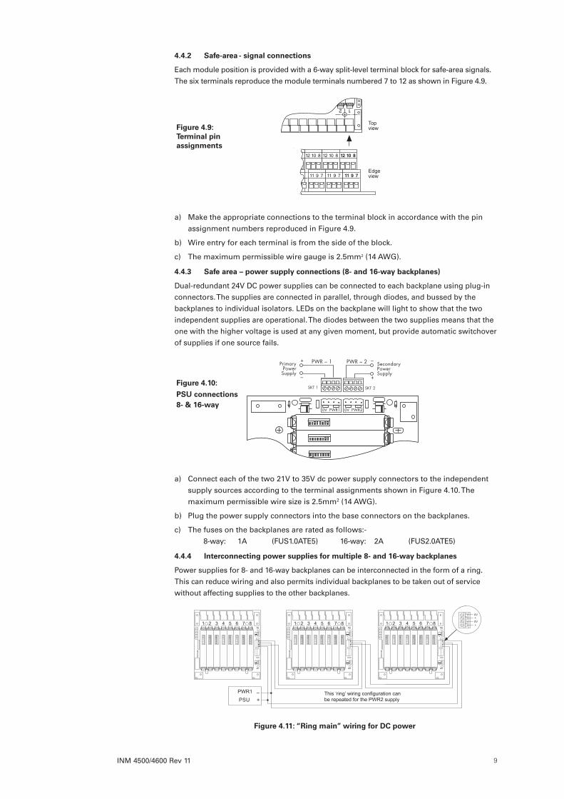
4 .4 .2 Safe-area - signal connections
Each module position is provided with a 6-way split-level terminal block for safe-area signals. The six terminals reproduce the module terminals numbered 7 to 12 as shown in Figure 4.9.
a) Make the appropriate connections to the terminal block in accordance with the pin assignment numbers reproduced in Figure 4.9.
b) Wire entry for each terminal is from the side of the block.
c) The maximum permissible wire gauge is 2.5mm2 (14 AWG).
4 .4 .3 Safe area – power supply connections (8- and 16-way backplanes)
Dual-redundant 24V DC power supplies can be connected to each backplane using plug-in connectors. The supplies are connected in parallel, through diodes, and bussed by the backplanes to individual isolators. LEDs on the backplane will light to show that the two independent supplies are operational. The diodes between the two supplies means that the one with the higher voltage is used at any given moment, but provide automatic switchover of supplies if one source fails.
a) Connect each of the two 21V to 35V dc power supply connectors to the independent supply sources according to the terminal assignments shown in Figure 4.10. The maximum permissible wire size is 2.5mm2 (14 AWG).
b) Plug the power supply connectors into the base connectors on the backplanes.
c) The fuses on the backplanes are rated as follows:- 8-way: 1A (FUS1.0ATE5) 16-way: 2A (FUS2.0ATE5)
4 .4 .4 Interconnecting power supplies for multiple 8- and 16-way backplanes
Power supplies for 8- and 16-way backplanes can be interconnected in the form of a ring. This can reduce wiring and also permits individual backplanes to be taken out of service without affecting supplies to the other backplanes.
This ‘ring’ wiring configuration can be repeated for the PWR2 supply+
–PSUPWR1
0V+0V+1 2 3 4 5 6 7 8
BP
S4508
1 2 3 4 5 6 7 8
BP
S4508
1 2 3 4 5 6 7 8
BP
S4508
Figure 4 .9: Terminal pin assignments
Figure 4 .10:
PSU connections 8- & 16-way
Figure 4 .11: “Ring main” wiring for DC power

INM 4500/4600 Rev 1110
More than one backplane can be removed, provided that they are immediate neighbours and ensures that other backplanes are not left without an active supply. The connection method is shown in Figure 4.11.
Note: a mixture of 8- and 16-way backplanes can be interconnected, provided that the maximum circuit current does not exceed 12A. Wire sizes up to 2.5mm2 (14 AWG) can be used and should be chosen after calculating the voltage drop for the current load.
4 .4 .5 Safe area – discrete power supply connections (24-way backplanes)
Dual-redundant 24V DC power supplies can be connected to each backplane using plug-in connectors. The supplies are connected in parallel, through diodes on the backplane, and bussed to individual isolators. LEDs on the backplane will light to show that the two independent supplies are operational. The diodes between the two supplies means that the one with the higher voltage is used at any given moment, but provide automatic switchover of supplies if one source fails.
a) Connect the power supply cables to the connector according to the pin assignments shown in Figure 4.12. The maximum permissible wire size is 2.5mm2 (14 AWG).
b) Plug the power supply connector into the base connector on the backplane.
c) The rating of the fuse is:– 24-way: 4.0A (FUS4.0ATE5 fuse kit)
4 .5 Backplanes – customised For information about installing customised backplanes (whether supplied by Eaton or by a third party), see the separate instructions provided with the units.
4 .6 Backplanes - module clip replacementAny broken module retaining clips must be replaced to maintain safe operation. Clips are constructed in moulded strips of four and are secured to the backplane with plastic rivets. Spare sets are available as part number SCK45 which contains 10 strips of four clips plus 40 rivets.
4 .6 .1 Changing a damaged strip
a) Identify the strip of four clips that includes the damaged clip and remove the modules that are retained by that strip.
b) Using a small pointed tool, such as a small screwdriver, push out from the underside the four rivets securing the clips and remove the strip.
c) Fit a new strip of four clips and insert new rivets, pressing them in fully. Do not reuse the existing rivets as they will be deformed by previous use.
Figure 4 .12: PSU connections 24-way
Figure 4 .13: Module clips and rivets
INM 4500/4600 Rev 11 11
5 INSTALLATION – MODULES
IMPORTANT
• Work should be carried out in accordance with all relevant local standards, codes of practice and site regulations.
• Check that the hazardous-area equipment complies with the descriptive system document.
• Refer to the certificate/catalogue for clarification of any aspects of intrinsic safety or contact Eaton’s MTL product line or your local representative for assistance.
• Make sure the correct hazardous-area connector (field-wiring plug) is plugged into the corresponding isolator. It is recommended that the connector is identified by the same tag
number as the matching isolator.
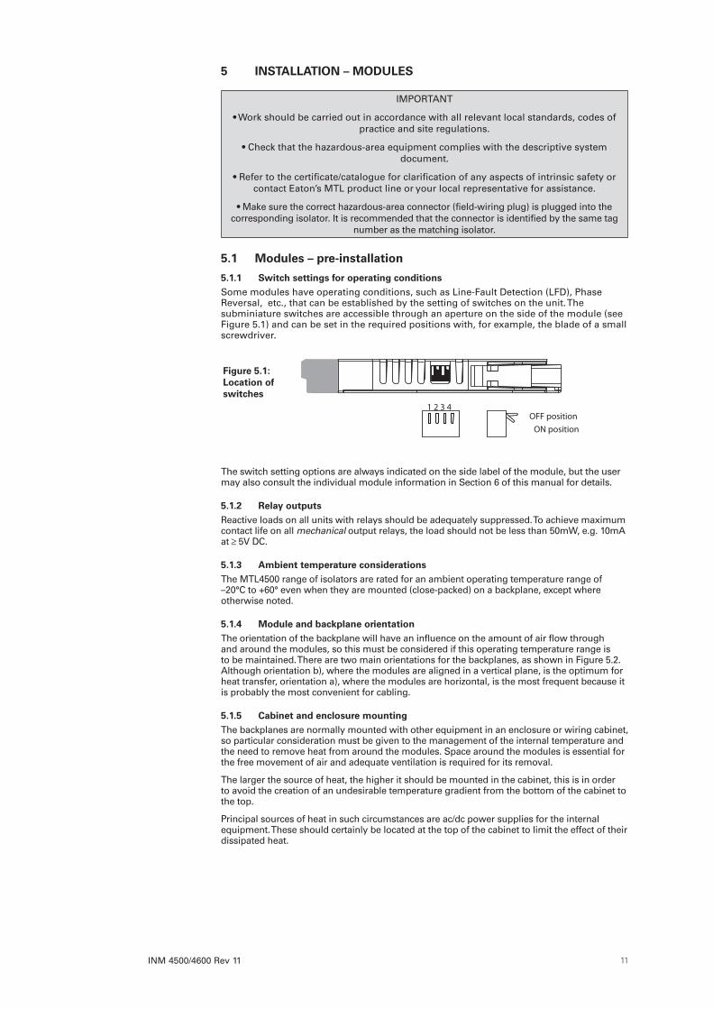
5 .1 Modules – pre-installation
5 .1 .1 Switch settings for operating conditionsSome modules have operating conditions, such as Line-Fault Detection (LFD), Phase Reversal, etc., that can be established by the setting of switches on the unit. The subminiature switches are accessible through an aperture on the side of the module (see Figure 5.1) and can be set in the required positions with, for example, the blade of a small screwdriver.
The switch setting options are always indicated on the side label of the module, but the user may also consult the individual module information in Section 6 of this manual for details.
5 .1 .2 Relay outputsReactive loads on all units with relays should be adequately suppressed. To achieve maximum contact life on all mechanical output relays, the load should not be less than 50mW, e.g. 10mA at 5V DC.
5 .1 .3 Ambient temperature considerationsThe MTL4500 range of isolators are rated for an ambient operating temperature range of –20°C to +60° even when they are mounted (close-packed) on a backplane, except where otherwise noted.
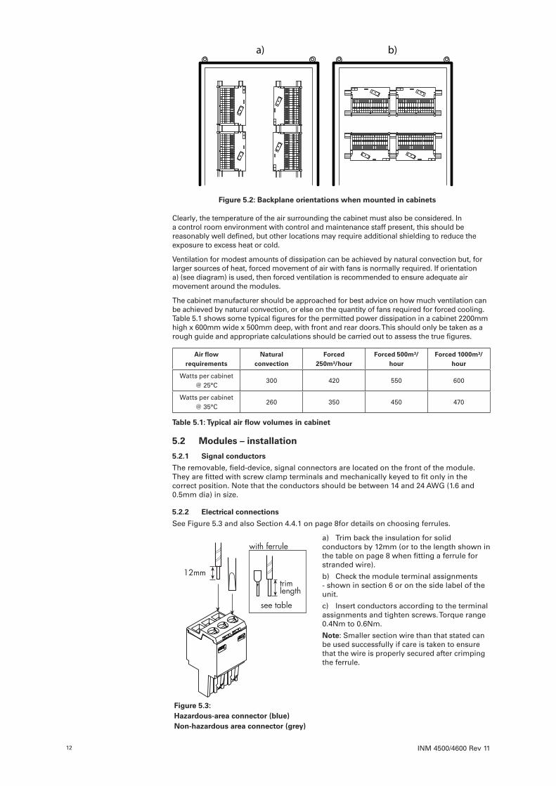
5 .1 .4 Module and backplane orientationThe orientation of the backplane will have an influence on the amount of air flow through and around the modules, so this must be considered if this operating temperature range is to be maintained. There are two main orientations for the backplanes, as shown in Figure 5.2. Although orientation b), where the modules are aligned in a vertical plane, is the optimum for heat transfer, orientation a), where the modules are horizontal, is the most frequent because it is probably the most convenient for cabling.
5 .1 .5 Cabinet and enclosure mountingThe backplanes are normally mounted with other equipment in an enclosure or wiring cabinet, so particular consideration must be given to the management of the internal temperature and the need to remove heat from around the modules. Space around the modules is essential for the free movement of air and adequate ventilation is required for its removal.
The larger the source of heat, the higher it should be mounted in the cabinet, this is in order to avoid the creation of an undesirable temperature gradient from the bottom of the cabinet to the top.
Principal sources of heat in such circumstances are ac/dc power supplies for the internal equipment. These should certainly be located at the top of the cabinet to limit the effect of their dissipated heat.
Figure 5 .1: Location of switches
OFF positionON position
1 2 3 4
INM 4500/4600 Rev 1112
Clearly, the temperature of the air surrounding the cabinet must also be considered. In a control room environment with control and maintenance staff present, this should be reasonably well defined, but other locations may require additional shielding to reduce the exposure to excess heat or cold.
Ventilation for modest amounts of dissipation can be achieved by natural convection but, for larger sources of heat, forced movement of air with fans is normally required. If orientation a) (see diagram) is used, then forced ventilation is recommended to ensure adequate air movement around the modules.
The cabinet manufacturer should be approached for best advice on how much ventilation can be achieved by natural convection, or else on the quantity of fans required for forced cooling. Table 5.1 shows some typical figures for the permitted power dissipation in a cabinet 2200mm high x 600mm wide x 500mm deep, with front and rear doors. This should only be taken as a rough guide and appropriate calculations should be carried out to assess the true figures.
Air flow requirements
Natural convection
Forced 250m³/hour
Forced 500m³/hour
Forced 1000m³/hour
Watts per cabinet @ 25°C
300 420 550 600
Watts per cabinet @ 35°C
260 350 450 470
Table 5 .1: Typical air flow volumes in cabinet
5 .2 Modules – installation
5 .2 .1 Signal conductors
The removable, field-device, signal connectors are located on the front of the module. They are fitted with screw clamp terminals and mechanically keyed to fit only in the correct position. Note that the conductors should be between 14 and 24 AWG (1.6 and 0.5mm dia) in size.
5 .2 .2 Electrical connections
See Figure 5.3 and also Section 4.4.1 on page 8for details on choosing ferrules.
a) Trim back the insulation for solid conductors by 12mm (or to the length shown in the table on page 8 when fitting a ferrule for stranded wire).
b) Check the module terminal assignments - shown in section 6 or on the side label of the unit.
c) Insert conductors according to the terminal assignments and tighten screws. Torque range 0.4Nm to 0.6Nm.
Note: Smaller section wire than that stated can be used successfully if care is taken to ensure that the wire is properly secured after crimping the ferrule.
a) b)
Figure 5 .2: Backplane orientations when mounted in cabinets
Figure 5 .3: Hazardous-area connector (blue)Non-hazardous area connector (grey)
INM 4500/4600 Rev 11 13
5 .2 .3 Finishing
Connect individual isolators in accordance with wiring schedules.
Ensure hazardous- and safe-area wiring is segregated into separate trunking or looms and maintain a tidy installation.
Use an MTL4599 dummy isolator to provide termination and earthing for unused cores from the hazardous area.
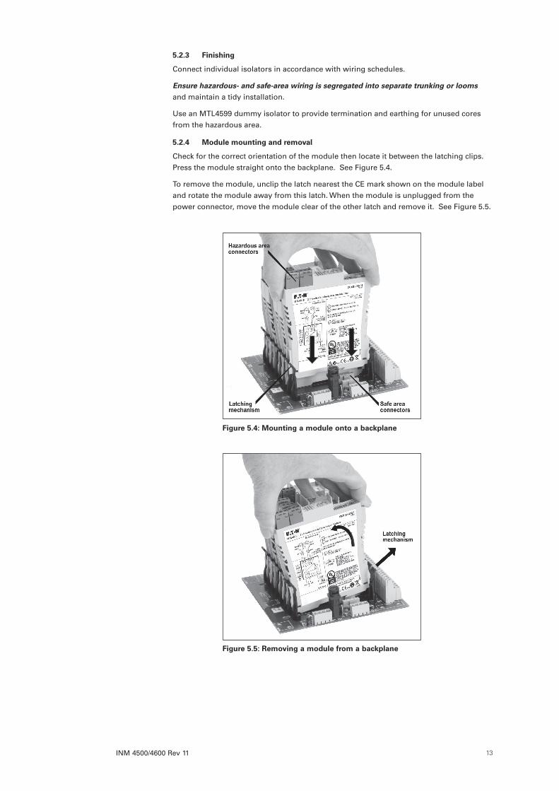
5 .2 .4 Module mounting and removal
Check for the correct orientation of the module then locate it between the latching clips. Press the module straight onto the backplane. See Figure 5.4.
To remove the module, unclip the latch nearest the CE mark shown on the module label and rotate the module away from this latch. When the module is unplugged from the power connector, move the module clear of the other latch and remove it. See Figure 5.5.
Figure 5 .4: Mounting a module onto a backplane
Figure 5 .5: Removing a module from a backplane
INM 4500/4600 Rev 1114
6 UNIT DESCRIPTIONS, SETTING-UP AND CONNECTIONSThis section describes the function (briefly), the setting-up procedure and the wiring connections for each MTL4500 range of unit. For a fuller functional description and a detailed technical specification, refer to the individual datasheets, which can be found on our website at http://www.mtl-inst.com or in the current MTL IS catalogue.
If a fault is suspected, first check that the power LED is lit (not applicable to loop-powered devices). If necessary, check that all signal and power plugs are properly inserted, that no wires are loose and that the unit is mounted correctly. If operation is still suspect, the unit should be replaced with a servicable unit.
There are no replaceable parts inside the MTL4500 range of units, so any that appear to be inoperative should be returned to the manufacturer/supplier for repair or replacement.
WARNING !MTL4500 range
When disconnecting units for maintenance purposes, take care to segregate hazardous and safe-area cables.
• Short circuit hazardous-area cable cores to an IS earth or insulate and secure the ends.
• Insulate and secure safe-area cables.
If testing a unit ‘in situ’ note that the test equipment used MUST be intrinsically safe.
The rest of this section is divided into sub-sections based upon the following module types.
6 .1 Digital Input modules MTL4501-SR, MTL4504, MTL4510, MTL4510B, MTL4511, MTL4513, MTL4514, MTL4514B, MTL4514D, MTL4514N, MTL4516, MTL4516C, MTL4517
6 .2 Digital Output modules MTL4521, MTL4521L, MTL4521Y, MTL4523, MTL4523Y, MTL4523L, MTL4523R, MTL4523V, MTL4523VL, MTL4524, MTL4524S, MTL4525, MTL4526
6-3 Pulse and Vibration modules MTL4531, MTL4532, MTL4533
6 .4 Analogue Input modules MTL4541, MTL4541A, MTL4541AS, MTL4541B, MTL4541P, MTL4541S, MTL4541 T, MTL4541YA, MTL4541Y, MTL4544, MTL4544A, MTL4544AS, MTL4544B, MTL4544D, MTL4544S
6 .5 Analogue Output modules MTL4545Y, MTL4546, MTL4546C, MTL4546S, MTL4546Y, MTL4549, MTL4549C, MTL4549Y
6-6 Fire and Smoke Interface modules MTL4561
6 .7 Temperature Input modules MTL4573, MTL4573Y, MTL4575, MTL4576-RTD, MTL4576-THC, MTL4581
6 .8 General modules MTL4599, MTL4599N
6 .9 PCS45/PCL45USB configurator for MTL temperature converters
Note: Any LED indicators provided on the modules will display in the following colours:
LED label LED colour
PWR (power) Green
STS (status) Yellow
LFD (line fault) Red
FLT (fault) Red
OPx (o/p status) Yellow
INM 4500/4600 Rev 11 15
6 .1 Digital Input modulesThe Digital Input (DI) module range offers solid state or relay output switches in a safe area that respond to input switches located in a hazardous area. Single or multiple channel (2 or 4) options are available, as well as Line-Fault Detection (LFD).
Modules with LFD can recognise open or short circuit conditions on the input wires going to the field sensors, and some DI modules have the facility to reverse the effect of the input on the output i.e. phase reversal.
These options are chosen with switches located on the edge of the module on the hazardous area terminal side. In some applications it may be easier to set these switches before fitting the module to the backplane.
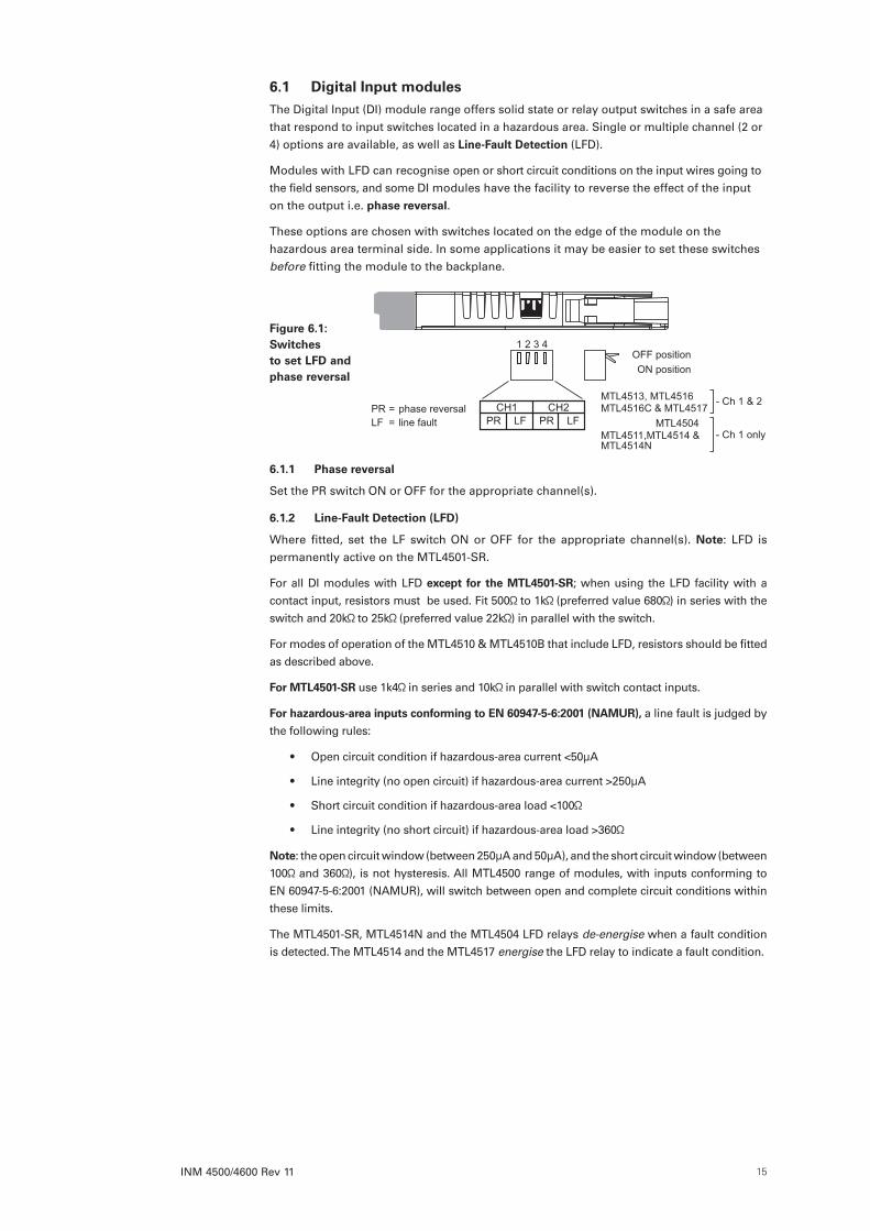
6 .1 .1 Phase reversal
Set the PR switch ON or OFF for the appropriate channel(s).
6 .1 .2 Line-Fault Detection (LFD)
Where fitted, set the LF switch ON or OFF for the appropriate channel(s). Note: LFD is permanently active on the MTL4501-SR.
For all DI modules with LFD except for the MTL4501-SR; when using the LFD facility with a contact input, resistors must be used. Fit 500 to 1k (preferred value 680 ) in series with the switch and 20k to 25k (preferred value 22k ) in parallel with the switch.
For modes of operation of the MTL4510 & MTL4510B that include LFD, resistors should be fitted as described above.
For MTL4501-SR use 1k4 in series and 10k in parallel with switch contact inputs.
For hazardous-area inputs conforming to EN 60947-5-6:2001 (NAMUR), a line fault is judged by the following rules:
• Open circuit condition if hazardous-area current <50µA
• Line integrity (no open circuit) if hazardous-area current >250µA
• Short circuit condition if hazardous-area load <100
• Line integrity (no short circuit) if hazardous-area load >360
Note: the open circuit window (between 250µA and 50µA), and the short circuit window (between 100 and 360 ), is not hysteresis. All MTL4500 range of modules, with inputs conforming to EN 60947-5-6:2001 (NAMUR), will switch between open and complete circuit conditions within these limits.
The MTL4501-SR, MTL4514N and the MTL4504 LFD relays de-energise when a fault condition is detected. The MTL4514 and the MTL4517 energise the LFD relay to indicate a fault condition.
OFF positionON position
1 2 3 4
CH1 CH2 PR LF PR LF
PR = phase reversalLF = line fault MTL4504
MTL4513, MTL4516MTL4516C & MTL4517
- Ch 1 & 2
- Ch 1 onlyMTL4511,MTL4514 &MTL4514N
Figure 6 .1: Switches to set LFD and phase reversal
INM 4500/4600 Rev 1116
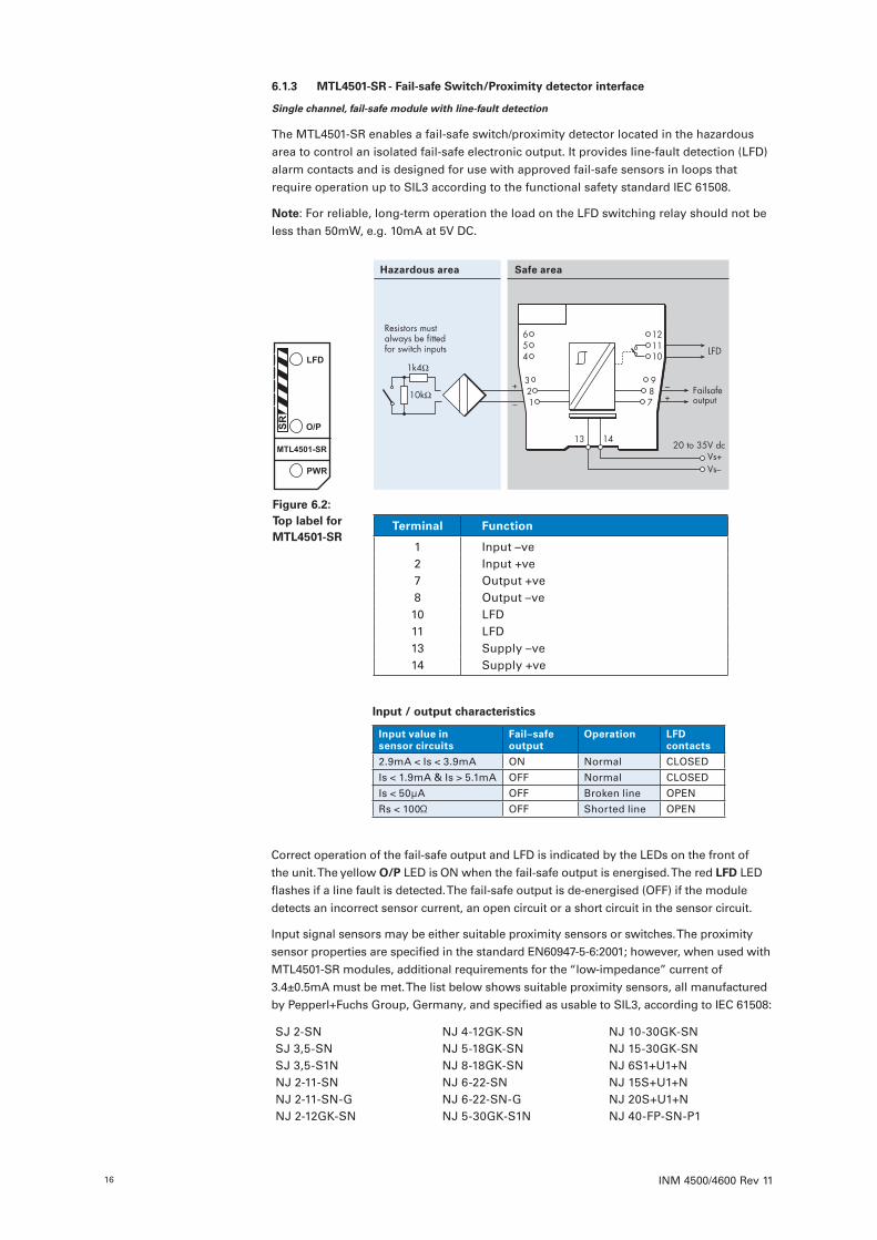
6 .1 .3 MTL4501-SR - Fail-safe Switch/Proximity detector interface
Single channel, fail-safe module with line-fault detection
The MTL4501-SR enables a fail-safe switch/proximity detector located in the hazardous area to control an isolated fail-safe electronic output. It provides line-fault detection (LFD) alarm contacts and is designed for use with approved fail-safe sensors in loops that require operation up to SIL3 according to the functional safety standard IEC 61508.
Note: For reliable, long-term operation the load on the LFD switching relay should not be less than 50mW, e.g. 10mA at 5V DC.
Figure 6 .2: Top label for MTL4501-SR
Terminal Function
1 Input –ve2 Input +ve7 Output +ve8 Output –ve10 LFD11 LFD13 Supply –ve14 Supply +ve
Hazardous area Safe area
Input / output characteristics
Input value in sensor circuits
Fail–safe output
Operation LFD contacts
2.9mA < Is < 3.9mA ON Normal CLOSED
Is < 1.9mA & Is > 5.1mA OFF Normal CLOSED
Is < 50µA OFF Broken line OPEN
Rs < 100 OFF Shorted line OPEN
Correct operation of the fail-safe output and LFD is indicated by the LEDs on the front of the unit. The yellow O/P LED is ON when the fail-safe output is energised. The red LFD LED flashes if a line fault is detected. The fail-safe output is de-energised (OFF) if the module detects an incorrect sensor current, an open circuit or a short circuit in the sensor circuit.
Input signal sensors may be either suitable proximity sensors or switches. The proximity sensor properties are specified in the standard EN60947-5-6:2001; however, when used with MTL4501-SR modules, additional requirements for the “low-impedance” current of 3.4±0.5mA must be met. The list below shows suitable proximity sensors, all manufactured by Pepperl+Fuchs Group, Germany, and specified as usable to SIL3, according to IEC 61508:
SJ 2-SN NJ 4-12GK-SN NJ 10-30GK-SNSJ 3,5-SN NJ 5-18GK-SN NJ 15-30GK-SNSJ 3,5-S1N NJ 8-18GK-SN NJ 6S1+U1+NNJ 2-11-SN NJ 6-22-SN NJ 15S+U1+NNJ 2-11-SN-G NJ 6-22-SN-G NJ 20S+U1+NNJ 2-12GK-SN NJ 5-30GK-S1N NJ 40-FP-SN-P1
INM 4500/4600 Rev 11 17
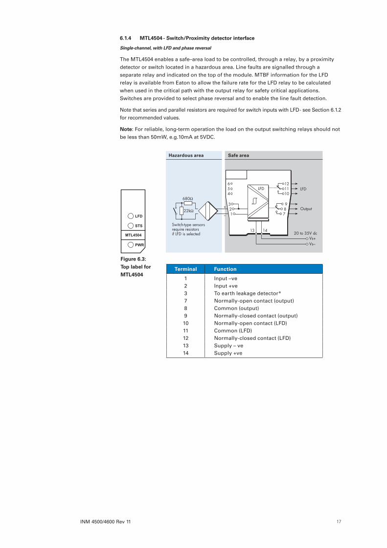
6 .1 .4 MTL4504 - Switch/Proximity detector interface
Single-channel, with LFD and phase reversal
The MTL4504 enables a safe–area load to be controlled, through a relay, by a proximity detector or switch located in a hazardous area. Line faults are signalled through a separate relay and indicated on the top of the module. MTBF information for the LFD relay is available from Eaton to allow the failure rate for the LFD relay to be calculated when used in the critical path with the output relay for safety critical applications. Switches are provided to select phase reversal and to enable the line fault detection.
Note that series and parallel resistors are required for switch inputs with LFD - see Section 6.1.2 for recommended values.
Note: For reliable, long-term operation the load on the output switching relays should not be less than 50mW, e.g.10mA at 5VDC.
Figure 6 .3:
Top label for
MTL4504
Hazardous area Safe area
22kΩ
680Ω
+
–
Output
LFD
Switch-type sensorsrequire resistorsif LFD is selected
Vs–Vs+
20 to 35V dc
To earth-leakage detector *
654
321
LFD
987
121110
13 14
Terminal Function
1 Input –ve2 Input +ve3 To earth leakage detector*7 Normally-open contact (output)8 Common (output)9 Normally-closed contact (output)10 Normally-open contact (LFD)11 Common (LFD)12 Normally-closed contact (LFD)13 Supply – ve14 Supply +ve
INM 4500/4600 Rev 1118
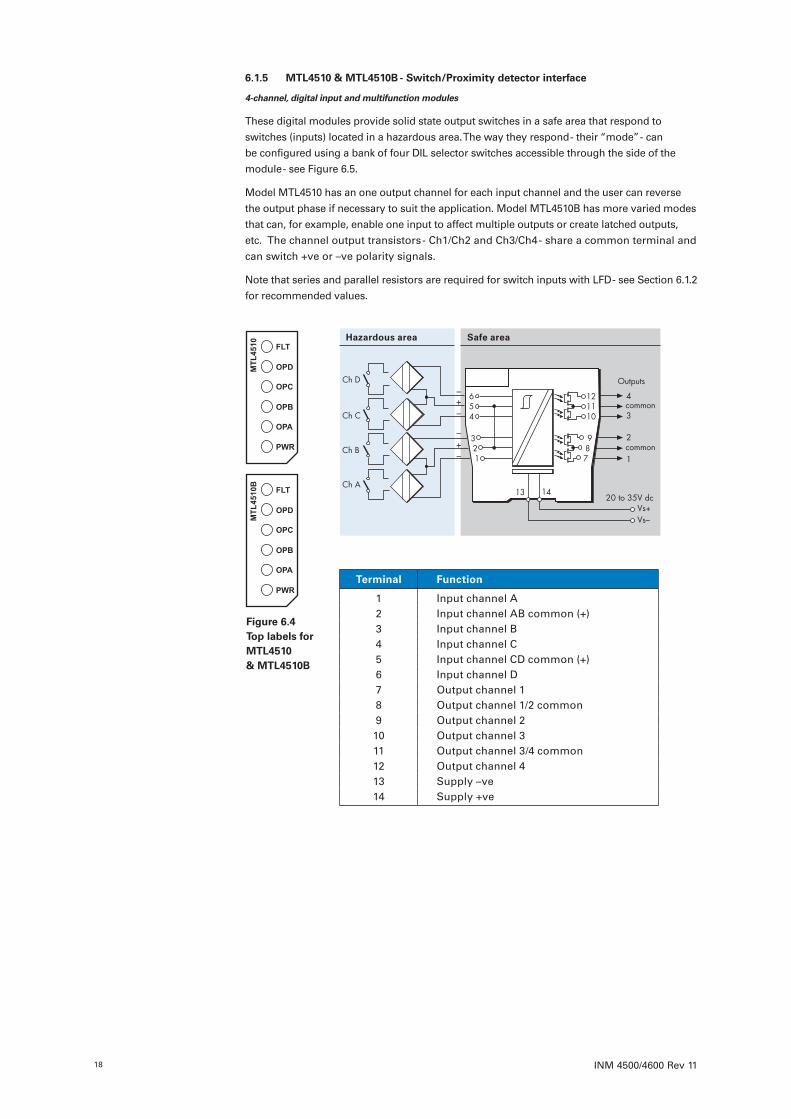
6 .1 .5 MTL4510 & MTL4510B - Switch/Proximity detector interface
4-channel, digital input and multifunction modules
These digital modules provide solid state output switches in a safe area that respond to switches (inputs) located in a hazardous area. The way they respond - their “mode” - can be configured using a bank of four DIL selector switches accessible through the side of the module - see Figure 6.5.
Model MTL4510 has an one output channel for each input channel and the user can reverse the output phase if necessary to suit the application. Model MTL4510B has more varied modes that can, for example, enable one input to affect multiple outputs or create latched outputs, etc. The channel output transistors - Ch1/Ch2 and Ch3/Ch4 - share a common terminal and can switch +ve or –ve polarity signals.
Note that series and parallel resistors are required for switch inputs with LFD - see Section 6.1.2 for recommended values.
Terminal Function
1 Input channel A2 Input channel AB common (+)3 Input channel B4 Input channel C5 Input channel CD common (+)6 Input channel D7 Output channel 18 Output channel 1/2 common9 Output channel 210 Output channel 311 Output channel 3/4 common12 Output channel 413 Supply –ve14 Supply +ve
Hazardous area Safe area
Ch B –+–
–+–
Ch D
Ch C
Ch A
1
2
3
4
common
common
Outputs
Vs–Vs+
20 to 35V dc
654
321
987
121110
13 14
Figure 6 .4 Top labels for MTL4510 & MTL4510B
INM 4500/4600 Rev 11 19
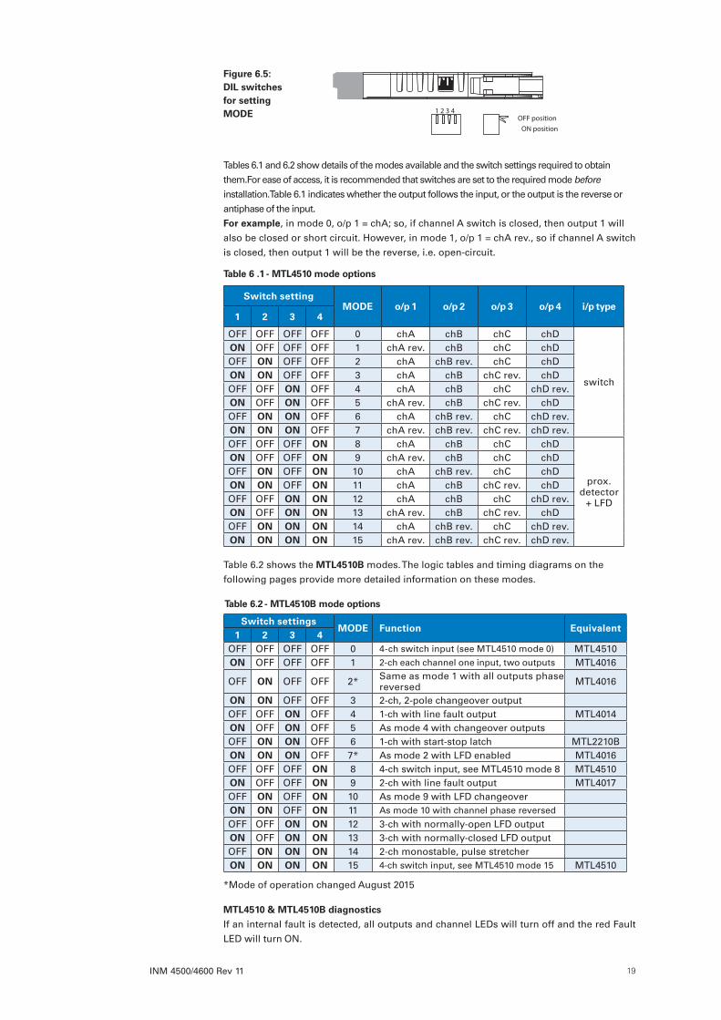
Tables 6.1 and 6.2 show details of the modes available and the switch settings required to obtain them.For ease of access, it is recommended that switches are set to the required mode before installation.Table 6.1 indicates whether the output follows the input, or the output is the reverse or antiphase of the input. For example, in mode 0, o/p 1 = chA; so, if channel A switch is closed, then output 1 will also be closed or short circuit. However, in mode 1, o/p 1 = chA rev., so if channel A switch is closed, then output 1 will be the reverse, i.e. open-circuit.
Table 6.2 shows the MTL4510B modes. The logic tables and timing diagrams on the following pages provide more detailed information on these modes.
*Mode of operation changed August 2015
MTL4510 & MTL4510B diagnostics
If an internal fault is detected, all outputs and channel LEDs will turn off and the red Fault LED will turn ON.
Table 6 .2 - MTL4510B mode options
Switch settingsMODE Function Equivalent
1 2 3 4OFF OFF OFF OFF 0 4-ch switch input (see MTL4510 mode 0) MTL4510ON OFF OFF OFF 1 2-ch each channel one input, two outputs MTL4016
OFF ON OFF OFF 2* Same as mode 1 with all outputs phase reversed MTL4016
ON ON OFF OFF 3 2-ch, 2-pole changeover outputOFF OFF ON OFF 4 1-ch with line fault output MTL4014ON OFF ON OFF 5 As mode 4 with changeover outputsOFF ON ON OFF 6 1-ch with start-stop latch MTL2210BON ON ON OFF 7* As mode 2 with LFD enabled MTL4016OFF OFF OFF ON 8 4-ch switch input, see MTL4510 mode 8 MTL4510ON OFF OFF ON 9 2-ch with line fault output MTL4017OFF ON OFF ON 10 As mode 9 with LFD changeoverON ON OFF ON 11 As mode 10 with channel phase reversed
OFF OFF ON ON 12 3-ch with normally-open LFD outputON OFF ON ON 13 3-ch with normally-closed LFD outputOFF ON ON ON 14 2-ch monostable, pulse stretcherON ON ON ON 15 4-ch switch input, see MTL4510 mode 15 MTL4510
Table 6 .1 - MTL4510 mode options
Switch settingMODE o/p 1 o/p 2 o/p 3 o/p 4 i/p type
1 2 3 4
OFF OFF OFF OFF 0 chA chB chC chD
switch
ON OFF OFF OFF 1 chA rev. chB chC chDOFF ON OFF OFF 2 chA chB rev. chC chDON ON OFF OFF 3 chA chB chC rev. chDOFF OFF ON OFF 4 chA chB chC chD rev.ON OFF ON OFF 5 chA rev. chB chC rev. chDOFF ON ON OFF 6 chA chB rev. chC chD rev.ON ON ON OFF 7 chA rev. chB rev. chC rev. chD rev.OFF OFF OFF ON 8 chA chB chC chD
prox. detector
+ LFD
ON OFF OFF ON 9 chA rev. chB chC chDOFF ON OFF ON 10 chA chB rev. chC chDON ON OFF ON 11 chA chB chC rev. chDOFF OFF ON ON 12 chA chB chC chD rev.ON OFF ON ON 13 chA rev. chB chC rev. chDOFF ON ON ON 14 chA chB rev. chC chD rev.ON ON ON ON 15 chA rev. chB rev. chC rev. chD rev.
OFF positionON position
1 2 3 4
Figure 6 .5: DIL switches for setting MODE

INM 4500/4600 Rev 1120
MTL4510B modes
The following logic and timing diagrams are provided to assist the user in understanding the behaviour of the MTL4510B module when a specific mode is chosen.
The open switch ( ) and closed switch ( ) symbols are used to represent both the input conditions of Ch A, Ch B, Ch C or Ch D and then the output conditions of o/p 1, 2, 3 or 4. Note that in certain modes a Line Fault can cause an override of the output.
How to use these mode tables - examples
The logic tables for Mode 1 represent Ch A controlling outputs 1 & 3, while Ch C controls outputs 2 & 4.
Output 1 & 3 are shown following input Ch A (open or closed) while Outputs 2 & 4 follow input Ch C.
Mode 2 however shows o/p 1, 2, 3 and 4 being in antiphase to their inputs.
Mode 9 operates with both outputs for each channel being in antiphase to their inputs.
Mode 3: 2 ch, 2 pole c/o output
i/p - Ch A i/p - Ch C
o/p 1 - -
o/p 2 - -
- - o/p 3
- - o/p 4
i/p - Ch A
No fault
Line fault
No fault
Line fault
o/p 1
Mode 4: 1 ch with line fault output
No fault
Line fault
No fault
Line fault
o/p 3
i/p - Ch A
No fault
Line fault
No fault
Line fault
o/p 1
o/p 2
Mode 5: As mode 4 with c/o outputs
No fault
Line fault
No fault
Line fault
LFD o/p 3
LFD o/p 4
A Start
BStop
i/p Ch A
i/p Ch B
o/p 2&4
o/p 1&3
BReset
*
* i/p Ch A can be open or closed when i/p Ch B opens to stop latch
Latching
Ch C closed
* i/p Ch A can be open or closed when i/p Ch B opens to stop latch
o/p 2&4
o/p 1&3
(enable)
i/p Ch A
i/p Ch B
Non-latching
Ch C open
Mode 1: 2 ch, each ch 1 input 2 outputs
i/p - Ch A i/p - Ch C
o/p 1 - -
- - o/p 2
o/p 3 - -
- - o/p 4
Mode 2: As mode 1 with all outputs phase reversed
i/p - Ch A i/p - Ch C
o/p 1 - -
- - o/p 2
o/p 3 - -
- - o/p 4
Mode 7: As mode 2 with LFD enabled
i/p - Ch A
No fault
Line fault
No fault
Line fault
o/p 1
o/p 3
i/p - Ch C
o/p 2
o/p 4
i/p Ch C Non-latching
i/p Ch B Enable
i/p Ch A
o/p 1
o/p 2
o/p 3
o/p 4
Mode 6: 1 ch with start/stop latch
OR
i/p Ch C Latching
i/p Ch A
i/p Ch B No effect
o/p 1
o/p 2
o/p 3
o/p 4
Start Reset
Stop

INM 4500/4600 Rev 11 21
MTL4510B modes - continued
Mode 14This mode provides a two channel pulse stretcher for in-puts A and C. Outputs 1 and 2 respond to Ch A, while 3 and 4 respond to Ch C.Input B (or D) being open or closed affects the input
i/p A (C)
o/p 2 (4)
o/p 1 (3)
Initiate
1sec (min.)
Endi/p B (D)
1sec (min.)
i/p A (C)
o/p 2 (4)
o/p 1 (3)
i/p B (D) Initiate End
transition and the output polarity as shown in the timing diagrams below.When triggered by A (or C) the outputs hold the change of state for a minimum of 1 second or as long as the input (A or C) remains in the same triggered state.
Input Ch B (or D) closed Input Ch B (or D) open
Mode 9: 2 ch with line fault output
i/p - Ch A
No fault
Line fault
No fault
Line fault
o/p 1
No fault
Line fault
No fault
Line fault
LFD o/p 3
i/p - Ch C
No fault
Line fault
No fault
Line fault
o/p 2
No fault
Line fault
No fault
Line fault
LFD o/p 3
LFD o/p 4
Mode 10: As mode 9 with line fault c/o
i/p - Ch A
No fault
Line fault
No fault
Line fault
o/p 1
i/p - Ch C
No fault
Line fault
No fault
Line fault
o/p 2
No fault
Line fault
No fault
Line fault
LFD o/p 3
LFD o/p 4
Mode 11: As mode 10 with ch phase reversed
i/p - Ch A
No fault
Line fault
No fault
Line fault
o/p 1
i/p - Ch C
No fault
Line fault
No fault
Line fault
o/p 2
No fault
Line fault
No fault
Line fault
LFD o/p 4
Mode 12: 3 ch with common LFD output
i/p - Ch A
No fault
Line fault
No fault
Line fault
o/p 1
i/p - Ch B
No fault
Line fault
No fault
Line fault
o/p 2
i/p - Ch C
No fault
Line fault
No fault
Line fault
o/p 3
Mode 13: As mode 12 but with LFD o/p 4 reversed
No fault
Line fault
No fault
Line fault
LFD o/p 4
INM 4500/4600 Rev 1122
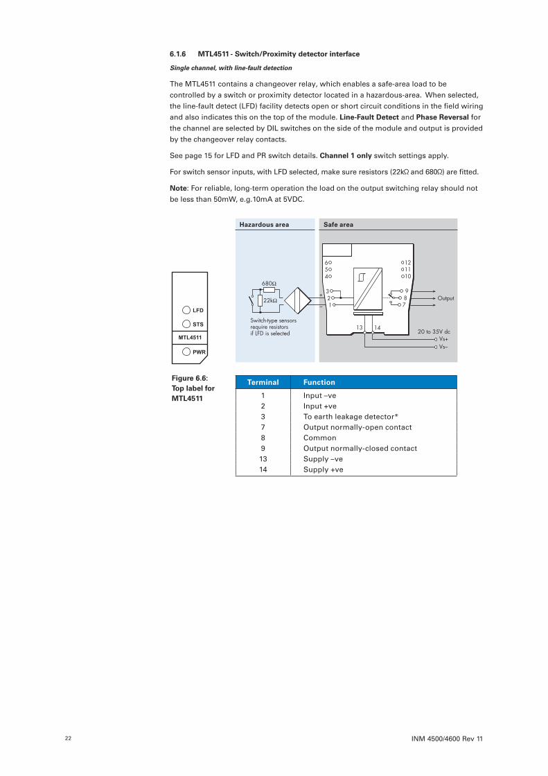
6 .1 .6 MTL4511 - Switch/Proximity detector interface
Single channel, with line-fault detection
The MTL4511 contains a changeover relay, which enables a safe-area load to be controlled by a switch or proximity detector located in a hazardous-area. When selected, the line-fault detect (LFD) facility detects open or short circuit conditions in the field wiring and also indicates this on the top of the module. Line-Fault Detect and Phase Reversal for the channel are selected by DIL switches on the side of the module and output is provided by the changeover relay contacts.
See page 15 for LFD and PR switch details. Channel 1 only switch settings apply.
For switch sensor inputs, with LFD selected, make sure resistors (22k and 680 ) are fitted.
Note: For reliable, long-term operation the load on the output switching relay should not be less than 50mW, e.g.10mA at 5VDC.
Terminal Function
1 Input –ve2 Input +ve3 To earth leakage detector*7 Output normally-open contact 8 Common9 Output normally-closed contact13 Supply –ve14 Supply +ve
Hazardous area Safe area
22kΩ
680Ω
+
–Output
Switch-type sensorsrequire resistorsif LFD is selected
Vs–Vs+
20 to 35V dc
654
321
987
121110
13 14
Figure 6 .6: Top label for MTL4511

INM 4500/4600 Rev 11 23
6 .1 .7 MTL4513 - Switch/Proximity detector interface
Two-channel, with line-fault detection and phase reversal
The MTL4513 enables two solid-state outputs in the safe area to be controlled by two switches or proximity detectors located in the hazardous area. The Ch1/Ch2 output transistors share a common terminal and can switch +ve or –ve polarity signals. Line-
Fault Detect and Phase Reversal for the channel are selected by DIL switches on the side of the module. LFD indication is provided on the top of the module.
See page 15 for LFD and PR switch details. Channel 1 & 2 switch settings apply.
For switch sensor inputs, with LFD selected, make sure resistors (22k and 680 ) are fitted.
Terminal Function
1 Input –ve (Ch 1)2 Input +ve (Ch 1)3 To earth leakage detector*4 Input –ve (Ch 2)5 Input +ve (Ch 2)6 To earth leakage detector*7 Output (Ch 1)8 Output (Ch 1/Ch 2)9 Output (Ch 2)13 Supply –ve14 Supply +ve
Hazardous area Safe area
Ch 1
Ch 2
Outputs
+–
22kΩ
680Ω
+
–
22kΩ
680Ω
Vs–Vs+
20 to 35V dcSwitch-type sensorsrequire resistors if LFD is selected
654
321
987
121110
13 14
Figure 6 .7: Top label for MTL4513
INM 4500/4600 Rev 1124
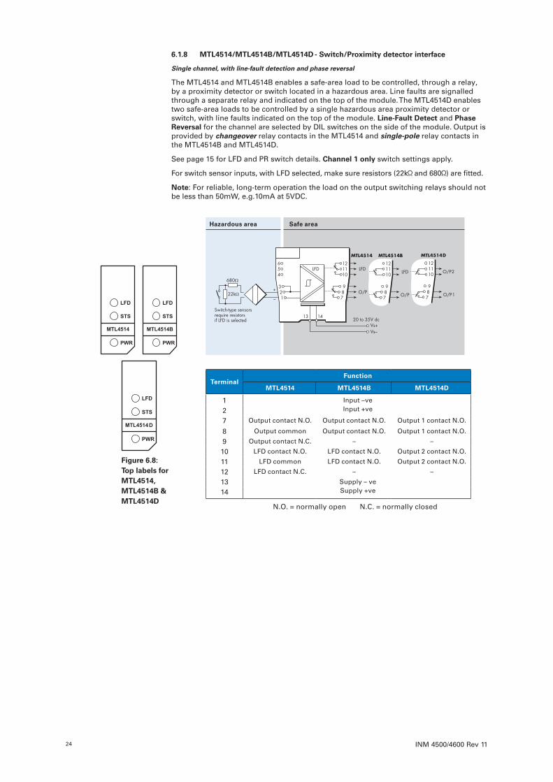
6 .1 .8 MTL4514/MTL4514B/MTL4514D - Switch/Proximity detector interface
Single channel, with line-fault detection and phase reversal
The MTL4514 and MTL4514B enables a safe-area load to be controlled, through a relay, by a proximity detector or switch located in a hazardous area. Line faults are signalled through a separate relay and indicated on the top of the module. The MTL4514D enables two safe-area loads to be controlled by a single hazardous area proximity detector or switch, with line faults indicated on the top of the module. Line-Fault Detect and Phase Reversal for the channel are selected by DIL switches on the side of the module. Output is provided by changeover relay contacts in the MTL4514 and single-pole relay contacts in the MTL4514B and MTL4514D.
See page 15 for LFD and PR switch details. Channel 1 only switch settings apply.
For switch sensor inputs, with LFD selected, make sure resistors (22k and 680 ) are fitted.
Note: For reliable, long-term operation the load on the output switching relays should not be less than 50mW, e.g.10mA at 5VDC.
TerminalFunction
MTL4514 MTL4514B MTL4514D
1 Input –veInput +ve2
7 Output contact N.O. Output contact N.O. Output 1 contact N.O.
8 Output common Output contact N.O. Output 1 contact N.O.
9 Output contact N.C. – –
10 LFD contact N.O. LFD contact N.O. Output 2 contact N.O.
11 LFD common LFD contact N.O. Output 2 contact N.O.
12 LFD contact N.C. – –
13 Supply – veSupply +ve14
N.O. = normally open N.C. = normally closed
Hazardous area Safe area
Figure 6 .8: Top labels for MTL4514, MTL4514B & MTL4514D
INM 4500/4600 Rev 11 25
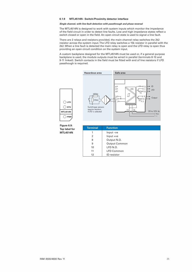
6 .1 .9 MTL4514N - Switch/Proximity detector interface
Single channel, with line-fault detection with passthrough and phase reversal
The MTL4514N is designed to work with system inputs which monitor the impedance of the field circuit in order to detect line faults. Low and high impedance states reflect a switch closed or open in the field. An open circuit state is used to signal a line fault.
There are 2 relays and resistors provided, the main channel relay switches the 2k2 resistor across the system input. The LFD relay switches a 15k resistor in parallel with the 2k2. When a line fault is detected the main relay is open and the LFD relay is open thus providing an open circuit condition on the system input.
A custom backplane designed for the MTL4514N must be used or, if a general purpose backplane is used, the module outputs must be wired in parallel (terminals 8-10 and 9-11 linked). Switch contacts in the field must be fitted with end of line resistors if LFD passthough is required.
Terminal Function
1 Input –ve2 Input +ve8 Output N.O.9 Output Common10 LFD N.O.11 LFD Common12 ID resistor
Hazardous area Safe area
Figure 6 .9: Top label for MTL4514N
22kΩ
680Ω
+
–
Output
LFD
Switch-type sensorsrequire resistorsif LFD is selected
Vs–Vs+
20 to 35V dc
To earth-leakage detector *
ID654
321
LFD
987
121110
13 14
15K
2K2
INM 4500/4600 Rev 1126
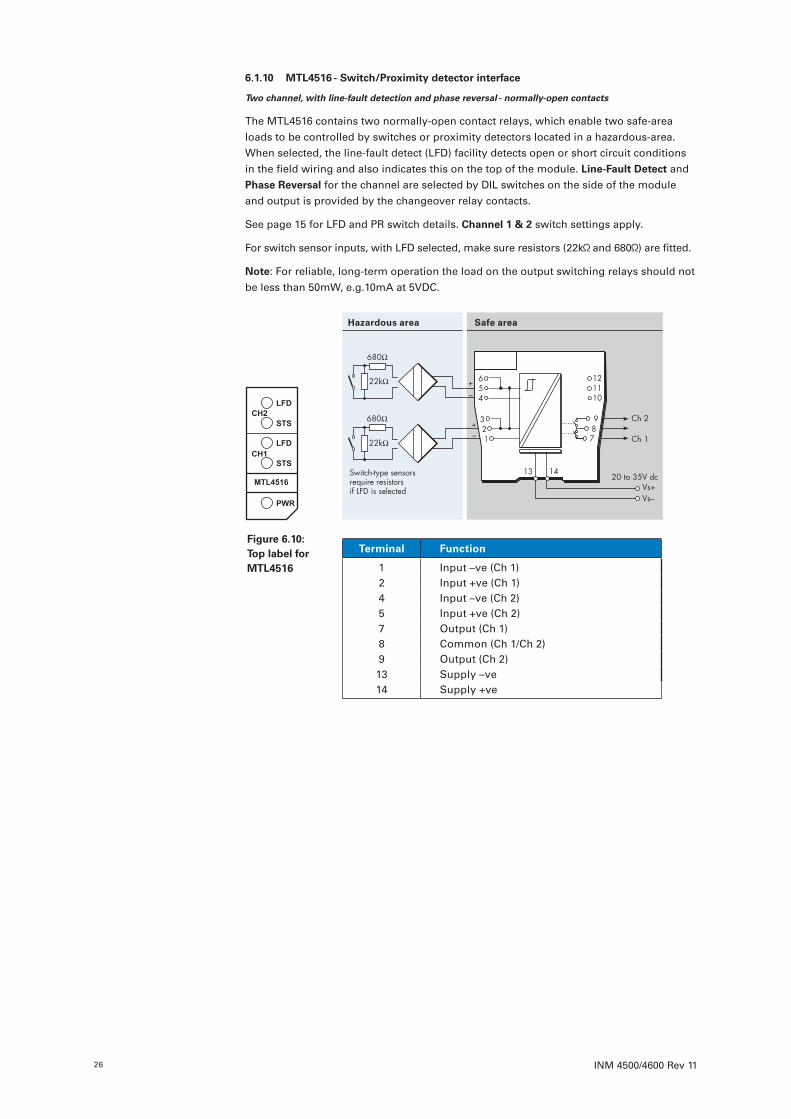
6 .1 .10 MTL4516 - Switch/Proximity detector interface
Two channel, with line-fault detection and phase reversal - normally-open contacts
The MTL4516 contains two normally-open contact relays, which enable two safe-area loads to be controlled by switches or proximity detectors located in a hazardous-area. When selected, the line-fault detect (LFD) facility detects open or short circuit conditions in the field wiring and also indicates this on the top of the module. Line-Fault Detect and Phase Reversal for the channel are selected by DIL switches on the side of the module and output is provided by the changeover relay contacts.
See page 15 for LFD and PR switch details. Channel 1 & 2 switch settings apply.
For switch sensor inputs, with LFD selected, make sure resistors (22k and 680 ) are fitted.
Note: For reliable, long-term operation the load on the output switching relays should not be less than 50mW, e.g.10mA at 5VDC.
Terminal Function
1 Input –ve (Ch 1)2 Input +ve (Ch 1)4 Input –ve (Ch 2)5 Input +ve (Ch 2)7 Output (Ch 1)8 Common (Ch 1/Ch 2)9 Output (Ch 2)13 Supply –ve14 Supply +ve
Hazardous area Safe area
22kΩ
680Ω+–
22kΩ
680Ω
+–
Ch 2
Ch 1
Switch-type sensorsrequire resistorsif LFD is selected
Vs–Vs+
20 to 35V dc
654
321
987
121110
13 14
Figure 6 .10: Top label for MTL4516

INM 4500/4600 Rev 11 27
6 .1 .11 MTL4516C - Switch/Proximity detector interface
Two channel, with line-fault detection and phase reversal - changeover contacts
The MTL4516C contains two changeover relays, which enable two safe-area loads to be controlled by switches or proximity detectors located in a hazardous-area. When selected, the line-fault detect (LFD) facility detects open or short circuit conditions in the field wiring and also indicates this on the top of the module. Line-Fault Detect and Phase
Reversal for the channel are selected by DIL switches on the side of the module and output is provided by the changeover relay contacts.
See page 15 for LFD and PR switch details. Channel 1 & 2 switch settings apply..
For switch sensor inputs, with LFD selected, make sure resistors (22k and 680 ) are fitted.
Note: For reliable, long-term operation the load on the output switching relays should not be less than 50mW, e.g.10mA at 5VDC.
Terminal Funct ion
1 Input –ve (Ch 1)2 Input +ve (Ch 1)4 Input –ve (Ch 2)5 Input +ve (Ch 2)7 Normally-open contact (Ch 1)8 Common (Ch 1)9 Normally-closed contact (Ch 1)10 Normally-open contact (Ch 2)11 Common (Ch 2)12 Normally-closed contact (Ch 2)13 Supply –ve14 Supply +ve
Hazardous area Safe area
+–
+
–Ch 2
Ch 1
22kΩ
680Ω
22kΩ
680Ω
Vs–Vs+
20 to 35V dcSwitch-type sensorsrequire resistorsif LFD is selected
654
321
987
121110
13 14
Figure 6 .11: Top label for MTL4516C
INM 4500/4600 Rev 1128
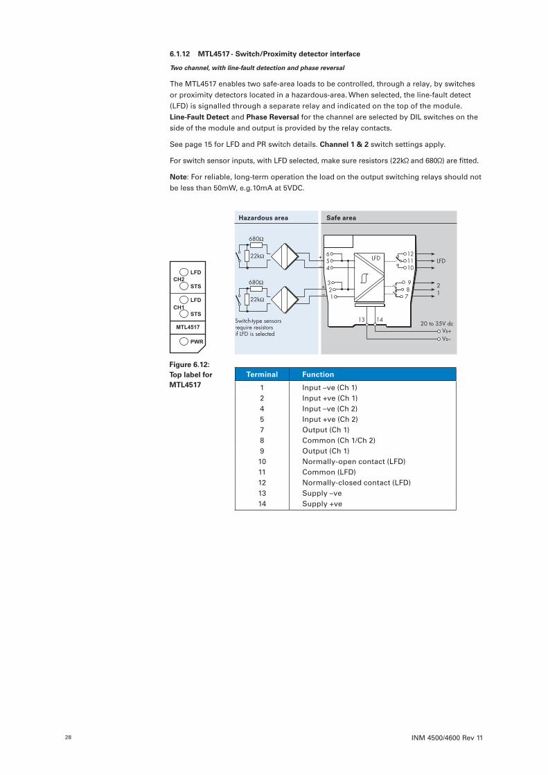
6 .1 .12 MTL4517 - Switch/Proximity detector interface
Two channel, with line-fault detection and phase reversal
The MTL4517 enables two safe-area loads to be controlled, through a relay, by switches or proximity detectors located in a hazardous-area. When selected, the line-fault detect (LFD) is signalled through a separate relay and indicated on the top of the module. Line-Fault Detect and Phase Reversal for the channel are selected by DIL switches on the side of the module and output is provided by the relay contacts.
See page 15 for LFD and PR switch details. Channel 1 & 2 switch settings apply.
For switch sensor inputs, with LFD selected, make sure resistors (22k and 680 ) are fitted.
Note: For reliable, long-term operation the load on the output switching relays should not be less than 50mW, e.g.10mA at 5VDC.
Terminal Function
1 Input –ve (Ch 1)2 Input +ve (Ch 1)4 Input –ve (Ch 2)5 Input +ve (Ch 2)7 Output (Ch 1)8 Common (Ch 1/Ch 2)9 Output (Ch 1)10 Normally-open contact (LFD)11 Common (LFD)12 Normally-closed contact (LFD)13 Supply –ve14 Supply +ve
Hazardous area Safe area
LFD
+–
+
–
Switch-type sensorsrequire resistorsif LFD is selected
122kΩ
680Ω
22kΩ
680Ω
Vs–Vs+
20 to 35V dc
2
654
321
LFD
987
121110
13 14
Figure 6 .12: Top label for MTL4517
INM 4500/4600 Rev 11 29
6 .2 Digital Output modulesThe single channel Digital Output (DO) module range enables on/off devices in a hazardous area to be controlled from the safe area. Some units are loop powered while others enable solid-state switching by providing independent power supplies.
6 .2 .1 MTL4521/MTL4521L - Solenoid Alarm driver
Single channel, loop powered, IIC
The MTL4521 and MTL4521L are loop-powered modules that enable a device located in the hazardous area (IIC gas group) to be controlled from the safe area. They can both drive up to 48mA into a certified intrinsically safe low-power load, as well as non-energy-storing simple apparatus such as an LED. The only difference is that the MTL4521L has a lower current safety description i.e. 108mA instead of 147mA.
Terminal Function
1 Output –ve2 Output +ve10 Supply +ve11 Supply –ve
Hazardous area Safe area
Figure 6 .13: Top labels for MTL4521 & MTL4521L
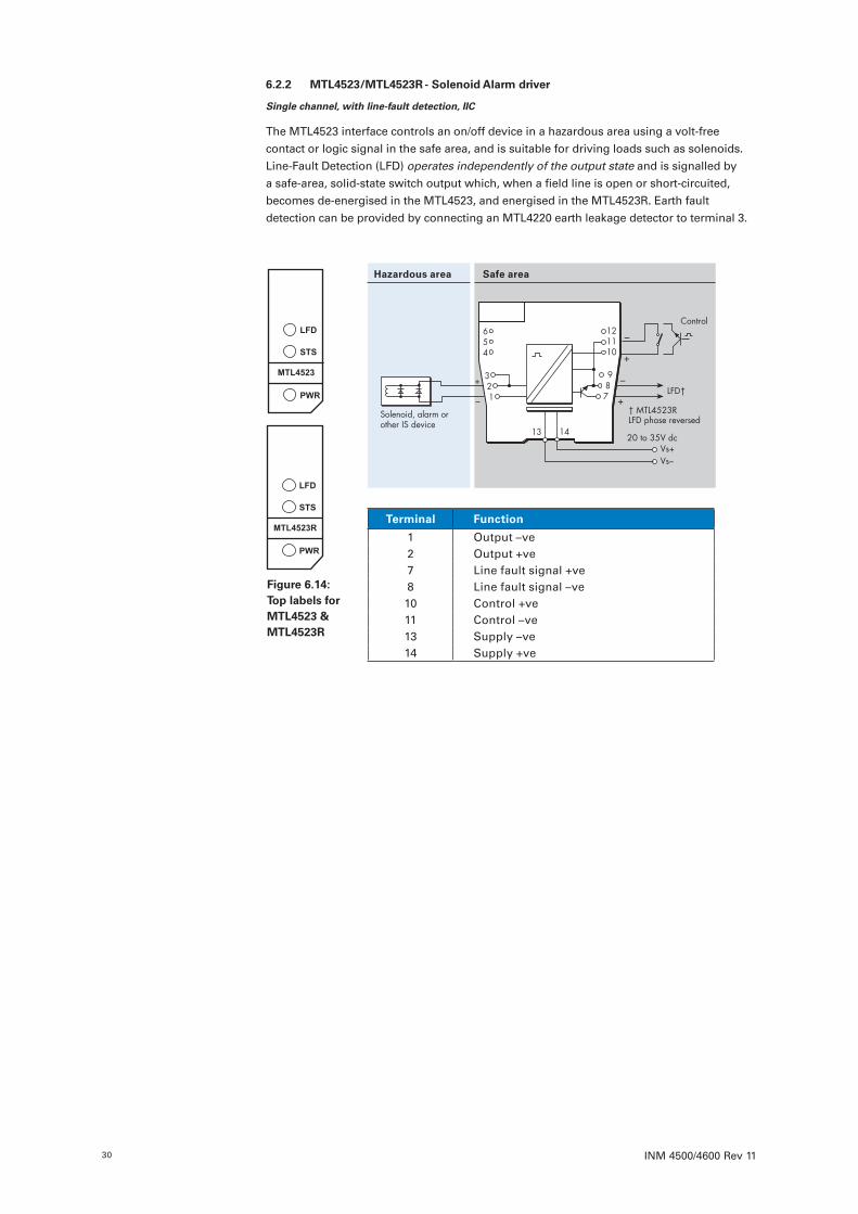
INM 4500/4600 Rev 1130
6 .2 .2 MTL4523/MTL4523R - Solenoid Alarm driver
Single channel, with line-fault detection, IIC
The MTL4523 interface controls an on/off device in a hazardous area using a volt-free contact or logic signal in the safe area, and is suitable for driving loads such as solenoids. Line-Fault Detection (LFD) operates independently of the output state and is signalled by a safe-area, solid-state switch output which, when a field line is open or short-circuited, becomes de-energised in the MTL4523, and energised in the MTL4523R. Earth fault detection can be provided by connecting an MTL4220 earth leakage detector to terminal 3.
Terminal Function
1 Output –ve2 Output +ve7 Line fault signal +ve8 Line fault signal –ve10 Control +ve11 Control –ve13 Supply –ve14 Supply +ve
Hazardous area Safe area
654
321
Solenoid, alarm orother IS device
+
–
+
–
LFD†
† MTL4523RLFD phase reversed
Vs–Vs+
20 to 35V dc
Control
+
–987
121110
13 14
Figure 6 .14: Top labels for MTL4523 & MTL4523R
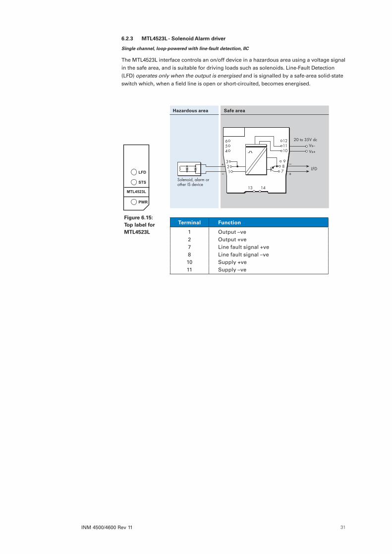
INM 4500/4600 Rev 11 31
6 .2 .3 MTL4523L - Solenoid Alarm driver
Single channel, loop-powered with line-fault detection, IIC
The MTL4523L interface controls an on/off device in a hazardous area using a voltage signal in the safe area, and is suitable for driving loads such as solenoids. Line-Fault Detection (LFD) operates only when the output is energised and is signalled by a safe-area solid-state switch which, when a field line is open or short-circuited, becomes energised.
Terminal Function
1 Output –ve2 Output +ve7 Line fault signal +ve8 Line fault signal –ve10 Supply +ve11 Supply –ve
Hazardous area Safe area
654
321
Solenoid, alarm orother IS device
+
–LFD
Vs–Vs+
20 to 35V dc
+
–987
121110
13 14
Figure 6 .15: Top label for MTL4523L
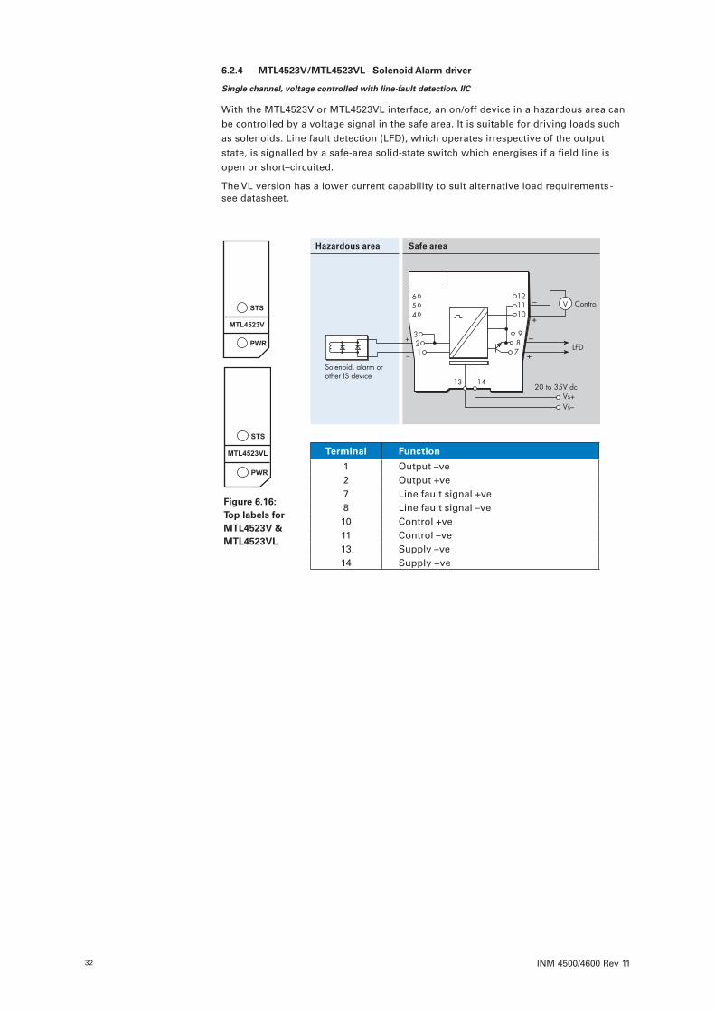
INM 4500/4600 Rev 1132
6 .2 .4 MTL4523V/MTL4523VL - Solenoid Alarm driver
Single channel, voltage controlled with line-fault detection, IIC
With the MTL4523V or MTL4523VL interface, an on/off device in a hazardous area can be controlled by a voltage signal in the safe area. It is suitable for driving loads such as solenoids. Line fault detection (LFD), which operates irrespective of the output state, is signalled by a safe-area solid-state switch which energises if a field line is open or short–circuited.
The VL version has a lower current capability to suit alternative load requirements - see datasheet.
Hazardous area Safe area
654
321
Solenoid, alarm orother IS device
+
–
+
–
LFD
Vs–Vs+
20 to 35V dc
Control
+
–987
121110
13 14
V
Terminal Function
1 Output –ve2 Output +ve7 Line fault signal +ve8 Line fault signal –ve10 Control +ve11 Control –ve13 Supply –ve14 Supply +ve
Figure 6 .16: Top labels for MTL4523V & MTL4523VL
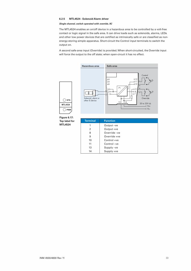
INM 4500/4600 Rev 11 33
6 .2 .5 MTL4524 - Solenoid Alarm driver
Single channel, switch operated with override, IIC
The MTL4524 enables an on/off device in a hazardous area to be controlled by a volt-free contact or logic signal in the safe area. It can drive loads such as solenoids, alarms, LEDs and other low power devices that are certified as intrinsically safe or are classified as non-energy-storing simple apparatus. Short-circuit the Control input terminals to switch the output on.
A second safe-area input (Override) is provided. When short-circuited, the Override input will force the output to the off state; when open-circuit it has no effect.
Terminal Function
1 Output –ve2 Output +ve8 Override –ve9 Override +ve10 Control +ve11 Control –ve13 Supply –ve14 Supply +ve
Hazardous area Safe area
654
321
Solenoid, alarm orother IS device
+
–
+
–
Vs–Vs+
20 to 35V dc
Control
+
–
Override
987
121110
13 14
Figure 6 .17: Top label for MTL4524
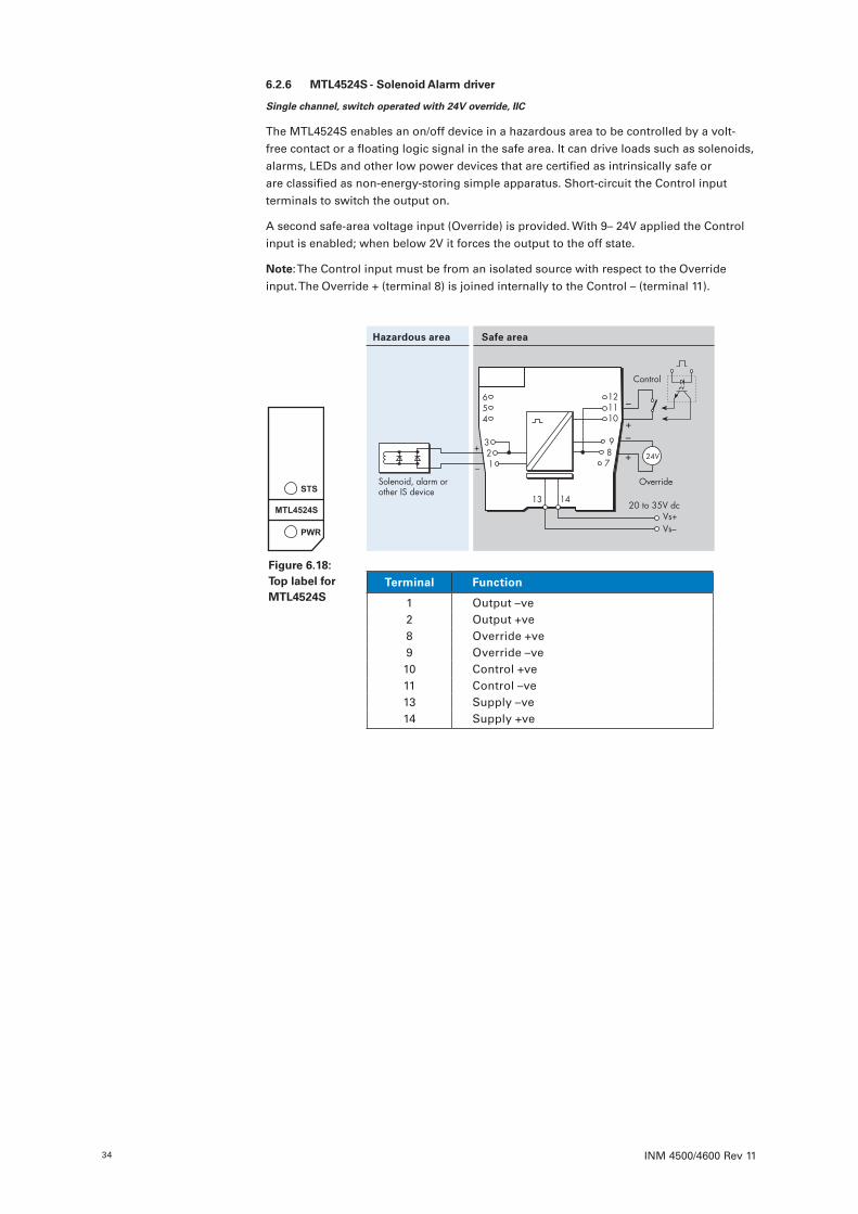
INM 4500/4600 Rev 1134
6 .2 .6 MTL4524S - Solenoid Alarm driver
Single channel, switch operated with 24V override, IIC
The MTL4524S enables an on/off device in a hazardous area to be controlled by a volt-free contact or a floating logic signal in the safe area. It can drive loads such as solenoids, alarms, LEDs and other low power devices that are certified as intrinsically safe or are classified as non-energy-storing simple apparatus. Short-circuit the Control input terminals to switch the output on.
A second safe-area voltage input (Override) is provided. With 9– 24V applied the Control input is enabled; when below 2V it forces the output to the off state.
Note: The Control input must be from an isolated source with respect to the Override input. The Override + (terminal 8) is joined internally to the Control – (terminal 11).
Terminal Function
1 Output –ve2 Output +ve8 Override +ve9 Override –ve10 Control +ve11 Control –ve13 Supply –ve14 Supply +ve
Hazardous area Safe area
654
321
Solenoid, alarm orother IS device
+
–
+
–
Vs–Vs+
20 to 35V dc
Control
+
–
Override
24V
987
121110
13 14
Figure 6 .18: Top label for MTL4524S
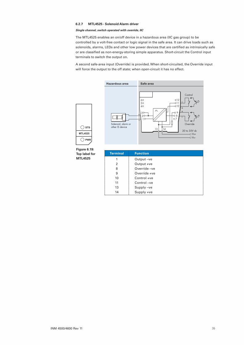
INM 4500/4600 Rev 11 35
6 .2 .7 MTL4525 - Solenoid Alarm driver
Single channel, switch operated with override, IIC
The MTL4525 enables an on/off device in a hazardous area (IIC gas group) to be controlled by a volt-free contact or logic signal in the safe area. It can drive loads such as solenoids, alarms, LEDs and other low power devices that are certified as intrinsically safe or are classified as non-energy-storing simple apparatus. Short-circuit the Control input terminals to switch the output on.
A second safe-area input (Override) is provided. When short-circuited, the Override input will force the output to the off state; when open-circuit it has no effect.
Terminal Function
1 Output –ve2 Output +ve8 Override –ve9 Override +ve10 Control +ve11 Control –ve13 Supply –ve14 Supply +ve
Hazardous area Safe area
654
321
Solenoid, alarm orother IS device
+
–
+
–
Vs–Vs+
20 to 35V dc
Control
+
–
Override
987
121110
13 14
Figure 6 .19: Top label for MTL4525
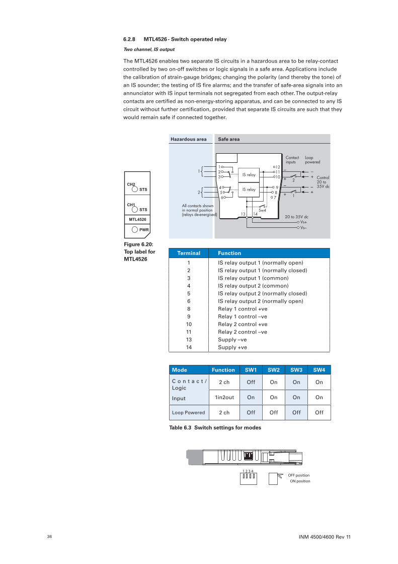
INM 4500/4600 Rev 1136
6 .2 .8 MTL4526 - Switch operated relay
Two channel, IS output
The MTL4526 enables two separate IS circuits in a hazardous area to be relay-contact controlled by two on-off switches or logic signals in a safe area. Applications include the calibration of strain-gauge bridges; changing the polarity (and thereby the tone) of an IS sounder; the testing of IS fire alarms; and the transfer of safe-area signals into an annunciator with IS input terminals not segregated from each other. The output-relay contacts are certified as non-energy-storing apparatus, and can be connected to any IS circuit without further certification, provided that separate IS circuits are such that they would remain safe if connected together.
Mode Function SW1 SW2 SW3 SW4
C o n t a c t /Logic
Input
2 ch Off On On On
1in2out On On On On
Loop Powered 2 ch Off Off Off Off
Terminal Function
1 IS relay output 1 (normally open)2 IS relay output 1 (normally closed)3 IS relay output 1 (common)4 IS relay output 2 (common)5 IS relay output 2 (normally closed)6 IS relay output 2 (normally open)8 Relay 1 control +ve9 Relay 1 control –ve10 Relay 2 control +ve11 Relay 2 control –ve13 Supply –ve14 Supply +ve
Hazardous area Safe area
123
456
IS relay
IS relay
1
2 +
–
+–
All contacts shown in normal position(relays de-energised)
Vs–Vs+
20 to 35V dc
+
–
+–
Control20 to 35V dc
Looppowered
Contactinputs
987
121110
1
2
Sw413 14
OFF positionON position
1 2 3 4
Figure 6 .20: Top label for MTL4526
Table 6 .3 Switch settings for modes

INM 4500/4600 Rev 11 37
6 .3 Pulse and Vibration modulesSingle and dual channel modules are available to transfer vibration probe signals from a hazardous area to a safe one. Similarly, pulses from a switch, proximity detector, current pulse transmitter or voltage pulse transmitter, located in the hazardous area, can be safely transferred to the safe area.
6 .3 .1 MTL4531 - Vibration Transducer Interface
Single channel
The MTL4531 repeats a signal from a vibration sensor in a hazardous area, providing an output for a monitoring system in the safe area. The interface is compatible with 3-wire, eddy-current probes and accelerometers or 2-wire current sensors, and selection of the mode is made with a switch located on the side of the module.
OFF positionON position
2-/3-wire
2-/3-wire transducer setting switch
Mode SW
2-wire (3 .3mA)* OFF
3-wire (20mA) ON
* Note: When using 2-wire sensors, ensure that terminals 1 and 2 are linked as shown in the wiring diagram above.
Terminal Function
1 Transducer power V–2 Signal3 Common7 Signal output 0V8 Signal output –ve13 Supply –ve14 Supply +ve
Hazardous area Safe area
654
321
Vibrationtransducer
Vibrationtransducer
Vs–Vs+
20 to 35V dc
987
121110
13 14
Monitor
COMSIGV–
–ve
0V
3-wire
2-wire 2
1
3
Figure 6 .21: Top label for MTL4531
WARNING!To enable optimum heat dissipation the recommended orientation for mounting is
with the module vertical, i.e. with the vents in the case at the top and bottom. This enables air to flow through the module.
In any other orientation, i.e. with the module horizontal, then the maximum ambient temperature is limited to:
• Close packed = 45°C• Minimum of one module spacing = 55°C
CAUTION:Exercise care when removing modules in operation from the middle of a group as
the surface temperature on the side faces may be very hot.

INM 4500/4600 Rev 1138
6 .3 .2 MTL4532 - Pulse Isolator
Pulse & 4/20mA current outputs
The MTL4532 isolates pulses from a switch, proximity detector, current pulse transmitter or voltage pulse transmitter located in a hazardous area. It is ideal for applications involving high pulse rates and fast response times, by repeating the pulses into the safe area, and the transistors used on the pulse output will switch +ve or –ve polarity signals.
It may be used immediately in simple or legacy mode, or it may be software configured for more specific applications - see next page for either option. With configuration, an analogue output proportional to frequency is available, together with a relay output, which may act as an alarm.
Note: For reliable, long-term operation the load on the output switching relay should not be less than 50mW, e.g.10mA at 5VDC.
Hazardous area Safe area
654
321
4/20mA
3-wirecurrentpulse
4/20mA
–
+
3-wirevoltagepulse
54
1
2-wirecurrentpulse
Voltagepulse
Currentpulse
5
1
Inhibit
Load
Alarm
4/20mA
Configurationsocket
–
+
1
4
+Pulse
–
+
Pulse
Vs–Vs+
20 to 35V dc4
3
V4/20mA
3
1
3 987
121110
13 14
Terminal Function
1 Common input –ve 2 Switch/proximity input +ve 3 Current pulse input +ve4 Transmitter supply +ve5 Voltage pulse input +ve6 Inhibit input +ve7 Pulse output +ve8 Pulse/Current output –ve9 Current output +ve11 Alarm/Current output –ve12 Alarm13 Supply –ve14 Supply +ve
Vsp SW1 SW2
3V ON ON
6V ON OFF
12V OFF OFF
OFF positionON position
1 2 3 4
SW1 SW2 SW3 SW4
Vsp Vsp LFD Mode
LFD SW3
OFF OFF
ON ON
Switches located on the edge of the module define the mode of operation.
Figure 6 .22: Top label for MTL4532
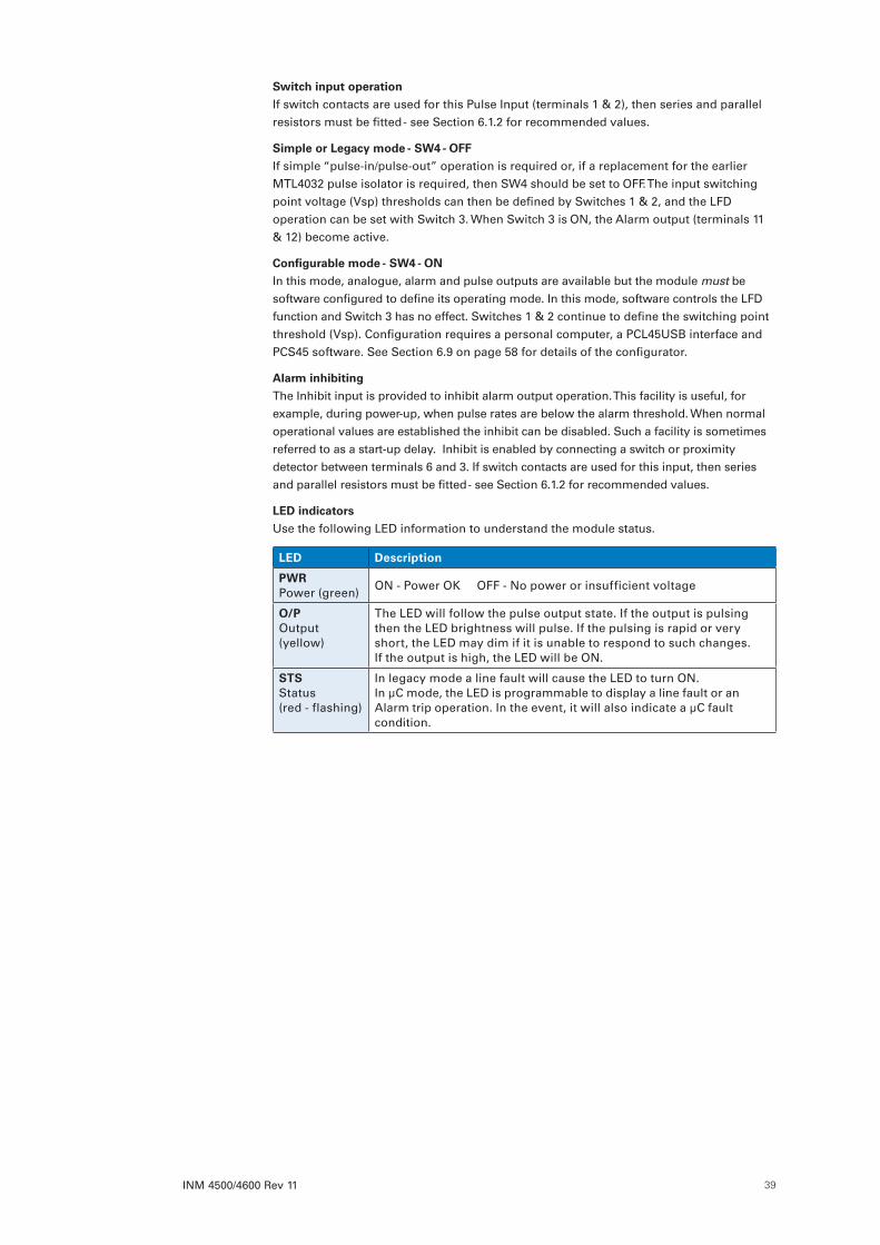
INM 4500/4600 Rev 11 39
Switch input operation
If switch contacts are used for this Pulse Input (terminals 1 & 2), then series and parallel resistors must be fitted - see Section 6.1.2 for recommended values.
Simple or Legacy mode - SW4 - OFF
If simple “pulse-in/pulse-out” operation is required or, if a replacement for the earlier MTL4032 pulse isolator is required, then SW4 should be set to OFF. The input switching point voltage (Vsp) thresholds can then be defined by Switches 1 & 2, and the LFD operation can be set with Switch 3. When Switch 3 is ON, the Alarm output (terminals 11 & 12) become active.
Configurable mode - SW4 - ON
In this mode, analogue, alarm and pulse outputs are available but the module must be software configured to define its operating mode. In this mode, software controls the LFD function and Switch 3 has no effect. Switches 1 & 2 continue to define the switching point threshold (Vsp). Configuration requires a personal computer, a PCL45USB interface and PCS45 software. See Section 6.9 on page 58 for details of the configurator.
Alarm inhibiting
The Inhibit input is provided to inhibit alarm output operation. This facility is useful, for example, during power-up, when pulse rates are below the alarm threshold. When normal operational values are established the inhibit can be disabled. Such a facility is sometimes referred to as a start-up delay. Inhibit is enabled by connecting a switch or proximity detector between terminals 6 and 3. If switch contacts are used for this input, then series and parallel resistors must be fitted - see Section 6.1.2 for recommended values.
LED indicators
Use the following LED information to understand the module status.
LED Description
PWR Power (green)
ON - Power OK OFF - No power or insufficient voltage
O/P Output (yellow)
The LED will follow the pulse output state. If the output is pulsing then the LED brightness will pulse. If the pulsing is rapid or very short, the LED may dim if it is unable to respond to such changes. If the output is high, the LED will be ON.
STS Status (red - flashing)
In legacy mode a line fault will cause the LED to turn ON. In µC mode, the LED is programmable to display a line fault or an Alarm trip operation. In the event, it will also indicate a µC fault condition.
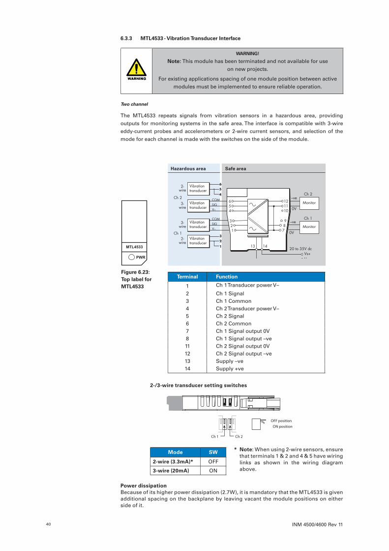
INM 4500/4600 Rev 1140
6 .3 .3 MTL4533 - Vibration Transducer Interface
WARNING!
Note: This module has been terminated and not available for use on new projects.
For existing applications spacing of one module position between active modules must be implemented to ensure reliable operation.
Two channel
The MTL4533 repeats signals from vibration sensors in a hazardous area, providing outputs for monitoring systems in the safe area. The interface is compatible with 3-wire eddy-current probes and accelerometers or 2-wire current sensors, and selection of the mode for each channel is made with the switches on the side of the module.
Hazardous area Safe area
Vibrationtransducer
Vibrationtransducer
Vibrationtransducer
Vibrationtransducer
COMSIGV–
COMSIGV–
–ve
0VMonitor
3-wire
2
1
3-wire
2-wire
5
4
2-wire
Monitor–ve
0V
3
6
Ch 1
Ch 2
Ch 1
Ch 2654
321
Vs–Vs+
20 to 35V dc
987
121110
13 14
Terminal Function
1 Ch 1 Transducer power V–
2 Ch 1 Signal3 Ch 1 Common4 Ch 2 Transducer power V–5 Ch 2 Signal6 Ch 2 Common7 Ch 1 Signal output 0V8 Ch 1 Signal output –ve11 Ch 2 Signal output 0V12 Ch 2 Signal output –ve13 Supply –ve14 Supply +ve
OFF positionON position
Ch 1 Ch 2
2-/3-wire transducer setting switches
Mode SW
2-wire (3 .3mA)* OFF
3-wire (20mA) ON
Power dissipationBecause of its higher power dissipation (2.7W), it is mandatory that the MTL4533 is given additional spacing on the backplane by leaving vacant the module positions on either side of it.
* Note: When using 2-wire sensors, ensure that terminals 1 & 2 and 4 & 5 have wiring links as shown in the wiring diagram above.
Figure 6 .23: Top label for MTL4533
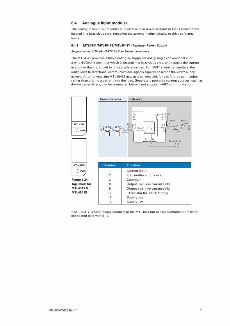
INM 4500/4600 Rev 11 41
Terminal Function
1 Current input2 Transmitter supply +ve3 Common8 Output –ve (+ve current sink)9 Output +ve (–ve current sink)12 ID resistor (MTL4541Y only)13 Supply –ve14 Supply +ve
Hazardous area Safe area
654
321
4/20mA
MTL4541 MTL4541S
+
Vs–Vs+
20 to 35V dc
–4/20mA
Load
Load
+
––
+
ComTx+
Input
I
I987
121110
13 14
*ID
6 .4 Analogue Input modulesThe analogue input (AI) modules support 2-wire or 3-wire 4/20mA or HART transmitters located in a hazardous area; repeating the current in other circuits to drive safe-area loads.
6 .4 .1 MTL4541/MTL4541S/MTL4541Y - Repeater Power Supply
Single channel, 4/20mA, HART® for 2- or 3-wire transmitters
The MTL4541 provides a fully-floating dc supply for energising a conventional 2- or 3-wire 4/20mA transmitter which is located in a hazardous area, and repeats the current in another floating circuit to drive a safe-area load. For HART 2-wire transmitters, the unit allows bi-directional communications signals superimposed on the 4/20mA loop current. Alternatively, the MTL4541S acts as a current sink for a safe-area connection rather than driving a current into the load. Seperately powered current sources, such as 4-wire transmitters, can be connected but will not support HART communication.
* MTL4541Y is functionally identical to the MTL4541 but has an additional ID resistor connected to terminal 12.
Figure 6 .24: Top labels for MTL4541 & MTL4541S
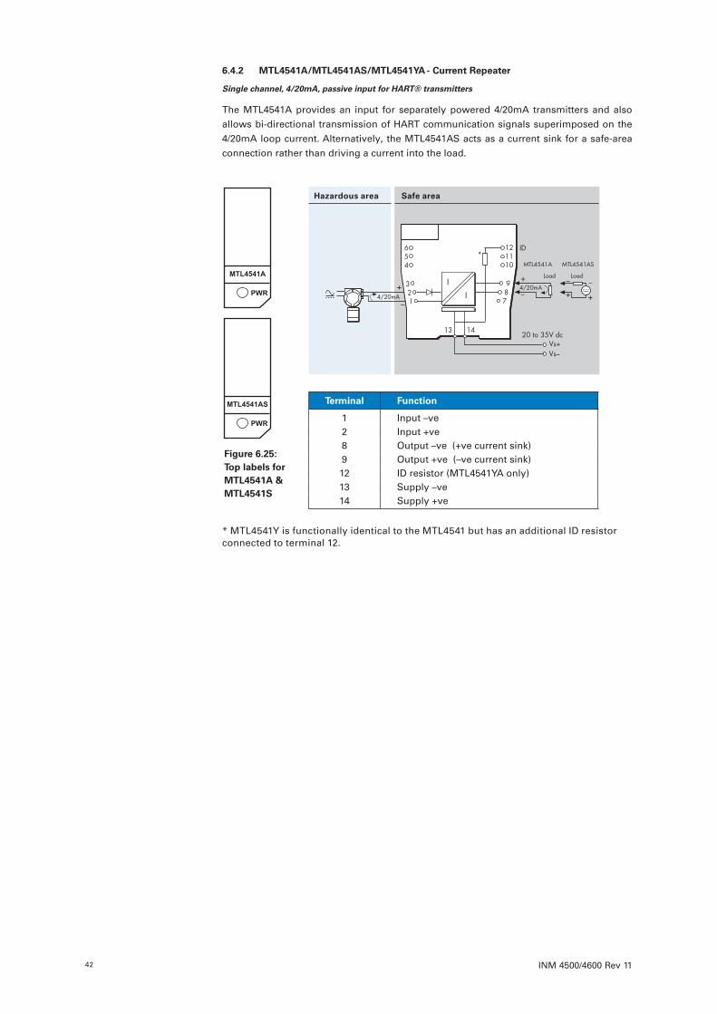
INM 4500/4600 Rev 1142
6 .4 .2 MTL4541A/MTL4541AS/MTL4541YA - Current Repeater
Single channel, 4/20mA, passive input for HART® transmitters
The MTL4541A provides an input for separately powered 4/20mA transmitters and also allows bi-directional transmission of HART communication signals superimposed on the 4/20mA loop current. Alternatively, the MTL4541AS acts as a current sink for a safe-area connection rather than driving a current into the load.
* MTL4541Y is functionally identical to the MTL4541 but has an additional ID resistor connected to terminal 12.
Terminal Function
1 Input –ve2 Input +ve8 Output –ve (+ve current sink)9 Output +ve (–ve current sink)12 ID resistor (MTL4541YA only)13 Supply –ve14 Supply +ve
Hazardous area Safe area
–4/20mA
Load+
–
+
MTL4541A MTL4541AS
Load
+
––
+
Vs–Vs+
20 to 35V dc
4/20mA
654
321
I
I987
121110
13 14
*ID
Figure 6 .25: Top labels for MTL4541A & MTL4541S
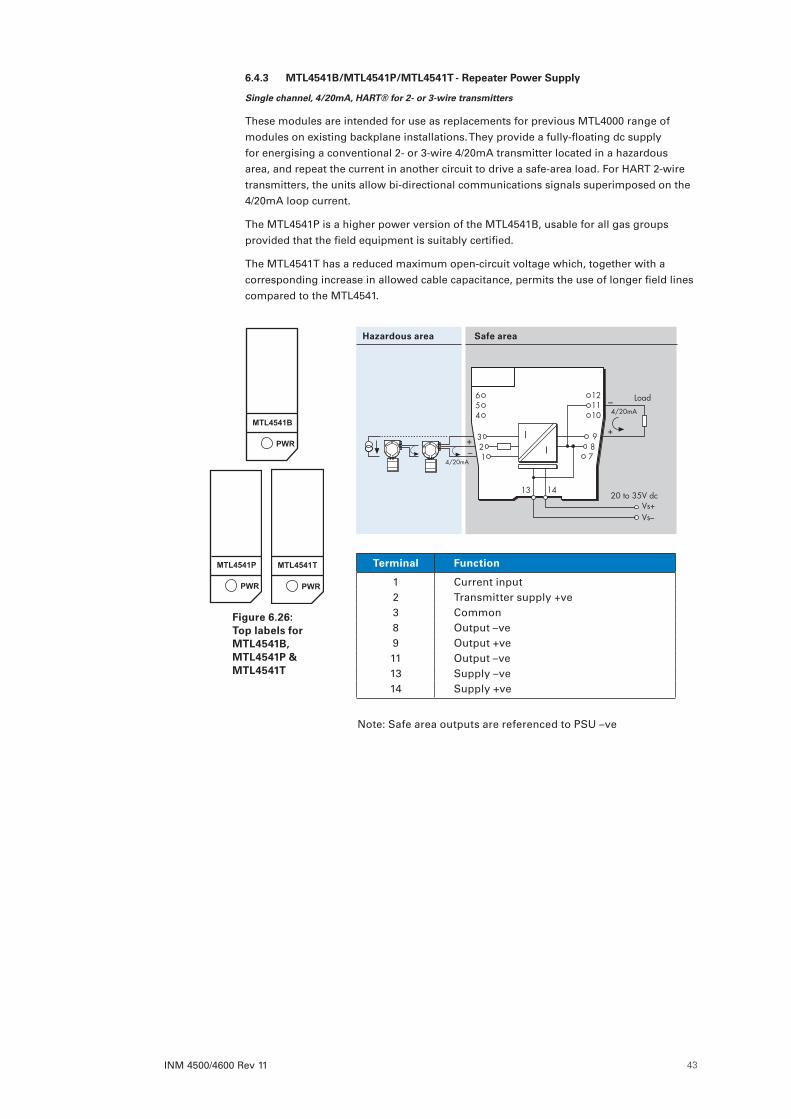
INM 4500/4600 Rev 11 43
6 .4 .3 MTL4541B/MTL4541P/MTL4541T - Repeater Power Supply
Single channel, 4/20mA, HART® for 2- or 3-wire transmitters
These modules are intended for use as replacements for previous MTL4000 range of modules on existing backplane installations. They provide a fully-floating dc supply for energising a conventional 2- or 3-wire 4/20mA transmitter located in a hazardous area, and repeat the current in another circuit to drive a safe-area load. For HART 2-wire transmitters, the units allow bi-directional communications signals superimposed on the 4/20mA loop current.
The MTL4541P is a higher power version of the MTL4541B, usable for all gas groups provided that the field equipment is suitably certified.
The MTL4541T has a reduced maximum open-circuit voltage which, together with a corresponding increase in allowed cable capacitance, permits the use of longer field lines compared to the MTL4541.
Hazardous area Safe area
Terminal Function
1 Current input2 Transmitter supply +ve3 Common8 Output –ve9 Output +ve11 Output –ve13 Supply –ve14 Supply +ve
Note: Safe area outputs are referenced to PSU –ve
654
321
+
Vs–Vs+
20 to 35V dc
–4/20mA
Load
+–
4/20mA
I
I987
121110
13 14
Figure 6 .26: Top labels for MTL4541B, MTL4541P & MTL4541T
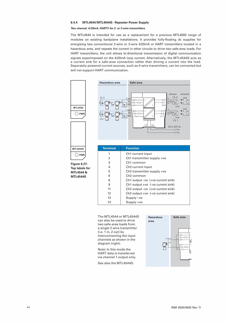
INM 4500/4600 Rev 1144
6 .4 .4 MTL4544/MTL4544S - Repeater Power Supply
Two channel, 4/20mA, HART® for 2- or 3-wire transmitters
The MTL4544 is intended for use as a replacement for a previous MTL4000 range of modules on existing backplane installations. It provides fully-floating dc supplies for energising two conventional 2-wire or 3-wire 4/20mA or HART transmitters located in a hazardous area, and repeats the current in other circuits to drive two safe-area loads. For HART transmitters, the unit allows bi-directional transmission of digital communication signals superimposed on the 4/20mA loop current. Alternatively, the MTL4544S acts as a current sink for a safe-area connection rather than driving a current into the load. Seperately powered current sources, such as 4-wire transmitters, can be connected but will not support HART communication.
Hazardousarea
Safe areaThe MTL4544 or MTL4544S can also be used to drive two safe-area loads from a single 2-wire transmitter (i.e. 1 in, 2 out) by interconnecting the input channels as shown in the diagram (right).
Note: In this mode the HART data is transferred via channel 1 output only.
See also the MTL4544D.
+
–
Vs–Vs+
20 to 35V dc
4/20mA
I
I
I
I
654
321
987
121110
14
Terminal Function
1 Ch1 current input2 Ch1 transmitter supply +ve3 Ch1 common4 Ch2 current input5 Ch2 transmitter supply +ve6 Ch2 common8 Ch1 output –ve (+ve current sink)9 Ch1 output +ve (–ve current sink)11 Ch2 output –ve (+ve current sink)12 Ch2 output +ve (–ve current sink)13 Supply –ve14 Supply +ve
Hazardous area Safe area
+
–4/20mA
Load
Ch 2
Ch 1
MTL4544 MTL4544S
4/20mA
4/20mA
Load
+
–
Vs–Vs+
20 to 35V dc
Ch 2
Ch 1
+
–4/20mA
Load
Load
+
–
ComTx+
Input
ComTx+
Input
I
I
I
I
654
321
987
121110
13 14
Figure 6 .27: Top labels for MTL4544 & MTL4544S

INM 4500/4600 Rev 11 45
6 .4 .5 MTL4544A/MTL4544AS - Current Repeater
Two channel, 4/20mA, passive input for HART® transmitters
The MTL4544A provides inputs for separately powered 4/20mA transmitters and also allows bi-directional transmission of HART communication signals superimposed on the 4/20mA loop current. Alternatively, the MTL4544AS acts as a current sink for a safe-area connection rather than driving a current into the load.
Terminal Function
1 Ch1 input –ve2 Ch1 input +ve4 Ch2 input –ve5 Ch2 input +ve8 Ch1 output –ve (+ve current sink)9 Ch1 output +ve (–ve current sink)11 Ch2 output –ve (+ve current sink)12 Ch2 output +ve (–ve current sink)13 Supply –ve14 Supply +ve
Hazardous area Safe area
Figure 6 .28: Top labels for MTL4544A & MTL4544AS
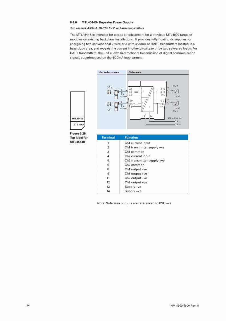
INM 4500/4600 Rev 1146
6 .4 .6 MTL4544B - Repeater Power Supply
Two channel, 4/20mA, HART® for 2- or 3-wire transmitters
The MTL4544B is intended for use as a replacement for a previous MTL4000 range of modules on existing backplane installations. It provides fully-floating dc supplies for energising two conventional 2-wire or 3-wire 4/20mA or HART transmitters located in a hazardous area, and repeats the current in other circuits to drive two safe-area loads. For HART transmitters, the unit allows bi-directional transmission of digital communication signals superimposed on the 4/20mA loop current.
Terminal Function
1 Ch1 current input2 Ch1 transmitter supply +ve3 Ch1 common4 Ch2 current input5 Ch2 transmitter supply +ve6 Ch2 common8 Ch1 output –ve9 Ch1 output +ve11 Ch2 output –ve12 Ch2 output +ve13 Supply –ve14 Supply +ve
Hazardous area Safe area
+
–4/20mA
Load
Ch 2
Ch 1
Vs–Vs+
20 to 35V dc
+
–4/20mA
Load
+–
+–
4/20mA
4/20mA
Ch 2
Ch 1
I
I
I
654
321
987
121110
13 14
Note: Safe area outputs are referenced to PSU –ve
Figure 6 .29: Top label for MTL4544B

INM 4500/4600 Rev 11 47
6 .4 .7 MTL4544D - Repeater Power Supply
Single channel, 4/20mA, HART® for 2- or 3-wire transmitters, two outputs
The MTL4544D provides a fully-floating dc supply for energising a conventional 2- or 3-wire 4/20mA transmitter located in a hazardous area, and repeats the current in other circuits to drive two safe-area loads. For HART 2-wire transmitters, the unit allows bi-directional transmission of digital communication signals superimposed on the 4/20mA loop current. Seperately powered current sources, such as 4-wire transmitters, can be connected but will not support HART communication.
Terminal Function
1 Current input2 Transmitter supply +ve3 Common8 Output 1 –ve
HART supported9 Output 1 +ve11 Output 2 –ve HART not
available12 Output 2 +ve13 Supply –ve14 Supply +ve
Hazardous area Safe area
+
–4/20mA
Load
O/P 2
O/P 1
Vs–Vs+
20 to 35V dc
+
–4/20mA
Load
I
I
I
654
321
987
121110
13 14
4/20mA
ComTx+
Input
NOTEFor correct operation of the module, a suitable load must be present on both output channels.
This is of particular importance during testing, commissioning or maintenance activities when the temporary disconnection, or absence, of a load can affect the transfer accuracy of the analogue variable.
Figure 6 .30: Top label for MTL4544D
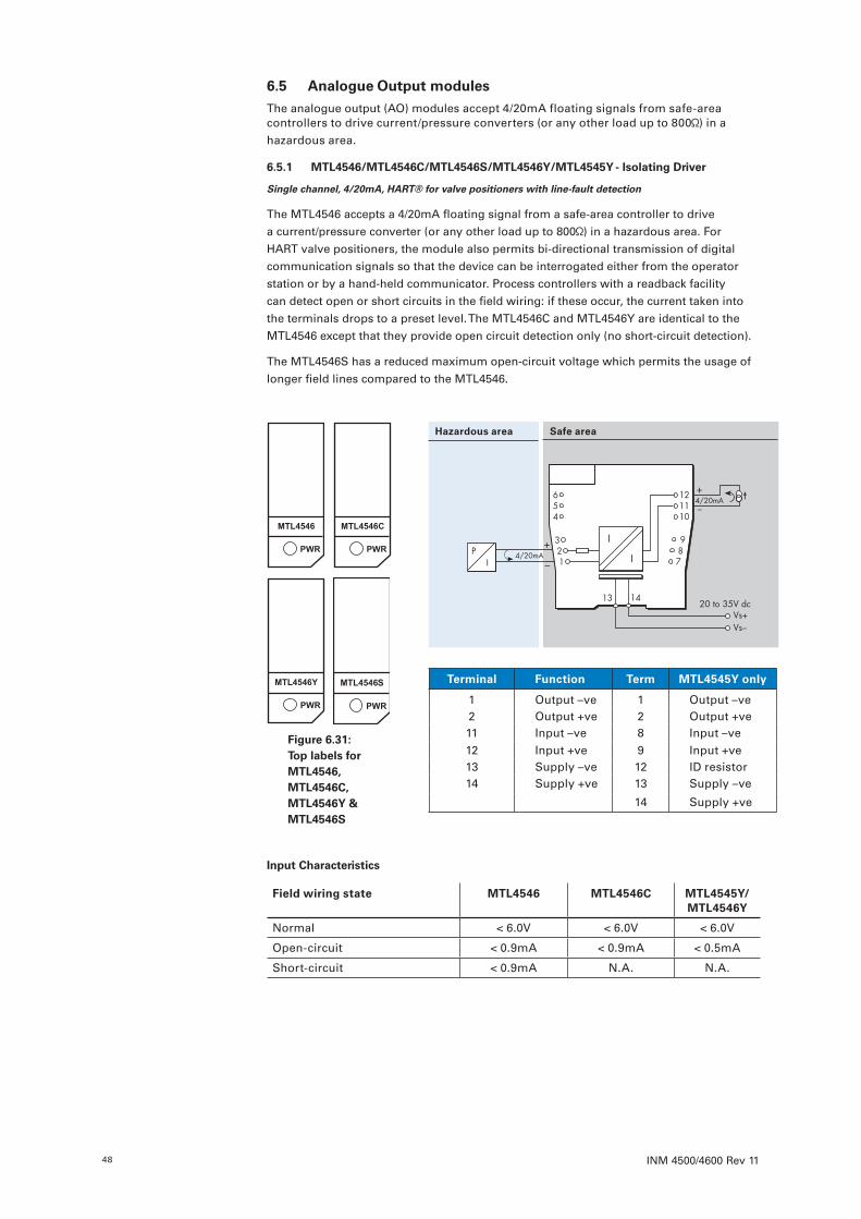
INM 4500/4600 Rev 1148
6 .5 Analogue Output modulesThe analogue output (AO) modules accept 4/20mA floating signals from safe-area controllers to drive current/pressure converters (or any other load up to 800 ) in a hazardous area.
6 .5 .1 MTL4546/MTL4546C/MTL4546S/MTL4546Y/MTL4545Y - Isolating Driver
Single channel, 4/20mA, HART® for valve positioners with line-fault detection
The MTL4546 accepts a 4/20mA floating signal from a safe-area controller to drive a current/pressure converter (or any other load up to 800 ) in a hazardous area. For HART valve positioners, the module also permits bi-directional transmission of digital communication signals so that the device can be interrogated either from the operator station or by a hand-held communicator. Process controllers with a readback facility can detect open or short circuits in the field wiring: if these occur, the current taken into the terminals drops to a preset level. The MTL4546C and MTL4546Y are identical to the MTL4546 except that they provide open circuit detection only (no short-circuit detection).
The MTL4546S has a reduced maximum open-circuit voltage which permits the usage of longer field lines compared to the MTL4546.
Input Characteristics
Field wiring state MTL4546 MTL4546C MTL4545Y/MTL4546Y
Normal < 6.0V < 6.0V < 6.0V
Open-circuit < 0.9mA < 0.9mA < 0.5mA
Short-circuit < 0.9mA N.A. N.A.
Terminal Function Term MTL4545Y only
1 Output –ve 1 Output –ve2 Output +ve 2 Output +ve11 Input –ve 8 Input –ve12 Input +ve 9 Input +ve13 Supply –ve 12 ID resistor14 Supply +ve 13 Supply –ve
14 Supply +ve
Hazardous area Safe area
–
+4/20mA
PI
4/20mA+
–
Vs–Vs+
20 to 35V dc
654
321
I
I
987
121110
13 14
S
Figure 6 .31: Top labels for MTL4546, MTL4546C, MTL4546Y & MTL4546S

INM 4500/4600 Rev 11 49
6 .5 .2 MTL4549/MTL4549C/MTL4549Y - Isolating Driver
Two channel, 4/20mA, HART® for valve positioners with line-fault detection
The MTL4549 accepts 4/20mA floating signals from safe-area controllers to drive 2 current/pressure converters (or any other load up to 800 ) in a hazardous area. For HART valve positioners, the module also permits bi-directional transmission of digital communication signals so that the device can be interrogated either from the operator station or by a hand-held communicator. Process controllers with a readback facility can detect open or short circuits in the field wiring: if these occur, the current taken into the terminals drops to a preset level. The MTL4549C and MTL4549Y are identical to the MTL4549 except that they provide open circuit detection only (no short-circuit detection).
Input Characteristics
Field wiring state MTL4549 MTL4549C MTL4549Y
Normal < 6.0V < 6.0V < 6.0V
Open-circuit < 0.9mA < 0.9mA < 0.5mA
Short-circuit < 0.9mA N.A. N.A.
Terminal Function
1 Output –ve (Ch 1)2 Output +ve (Ch 1)4 Output –ve (Ch 2)5 Output +ve (Ch 2)8 Input –ve (Ch 1)9 Input +ve (Ch 1)11 Input –ve (Ch 2)12 Input +ve (Ch 2) 13 Supply –ve14 Supply +ve
Hazardous area Safe area
4/20mAP
I
+
–
PI
+
–
+4/20mA
Ch 2
Ch 1
Ch 2
Ch 1–4/20mA
4/20mA
Vs–Vs+
20 to 35V dc
+
–
654
321
I
I
I
I
987
121110
13 14
Figure 6 .32: Top labels for MTL4549 MTL4549C & MTL4549Y
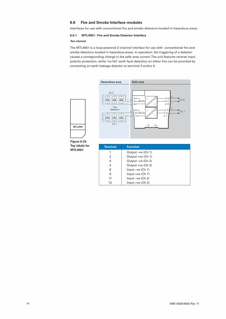
INM 4500/4600 Rev 1150
6 .6 Fire and Smoke Interface modulesInterfaces for use with conventional fire and smoke detectors located in hazardous areas.
6 .6 .1 MTL4561 - Fire and Smoke Detector Interface
Two channel
The MTL4561 is a loop-powered 2–channel interface for use with conventional fire and smoke detectors located in hazardous areas. In operation, the triggering of a detector causes a corresponding change in the safe–area current. The unit features reverse input polarity protection, while ‘no-fail’ earth fault detection on either line can be provided by connecting an earth leakage detector to terminal 3 and/or 6.
Hazardous area Safe area
–
–
++
–
+
–
Ch 2
Ch 1
Ch 2
Ch 1
+654
321
I
I
I
IFire
detectors 987
121110
13 14
Terminal Function
1 Output –ve (Ch 1)2 Output +ve (Ch 1)4 Output –ve (Ch 2)5 Output +ve (Ch 2)8 Input –ve (Ch 1)9 Input +ve (Ch 1)11 Input –ve (Ch 2)12 Input +ve (Ch 2)
Figure 6 .33: Top labels for MTL4561
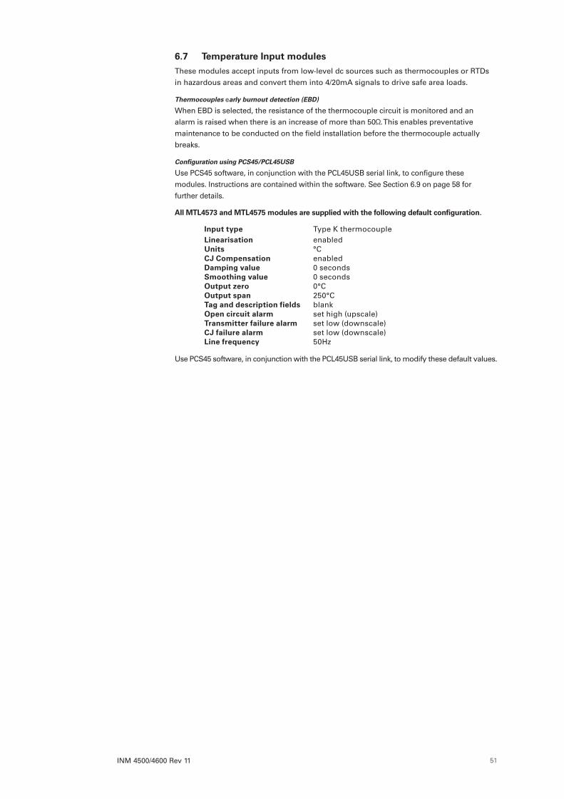
INM 4500/4600 Rev 11 51
6 .7 Temperature Input modulesThese modules accept inputs from low-level dc sources such as thermocouples or RTDs in hazardous areas and convert them into 4/20mA signals to drive safe area loads.
Thermocouples early burnout detection (EBD)
When EBD is selected, the resistance of the thermocouple circuit is monitored and an alarm is raised when there is an increase of more than 50 . This enables preventative maintenance to be conducted on the field installation before the thermocouple actually breaks.
Configuration using PCS45/PCL45USB
Use PCS45 software, in conjunction with the PCL45USB serial link, to configure these modules. Instructions are contained within the software. See Section 6.9 on page 58 for further details.
All MTL4573 and MTL4575 modules are supplied with the following default configuration .
Input type Type K thermocoupleLinearisation enabledUnits °CCJ Compensation enabledDamping value 0 secondsSmoothing value 0 secondsOutput zero 0°COutput span 250°CTag and description fields blankOpen circuit alarm set high (upscale)Transmitter failure alarm set low (downscale)CJ failure alarm set low (downscale)Line frequency 50Hz
Use PCS45 software, in conjunction with the PCL45USB serial link, to modify these default values.

INM 4500/4600 Rev 1152
6 .7 .1 MTL4573 - Temperature Converter
Single channel, THC or RTD input
The MTLx573 converts a low-level dc signal from a temperature sensor mounted in a hazardous area into a 4/20mA current for driving a safe-area load. Software selectable features include linearisation, ranging, monitoring, testing and tagging for all thermocouple types and 2-, 3- or 4-wire RTDs. (For thermocouple applications the HAZ-CJC plug on terminals 1–3 includes an integral CJC sensor). Configuration is carried out using a personal computer with PCS45 software.
Top label
Use the following LED information to understand the module status.
Status PWR (green) STS(yellow)
Power ON ON
Insufficient voltage or Power OFF OFF
Normal working ON
Device failure FLASH
Sensor failure/Error FLASH
Early burnout detection (EBD) FAST FLASH
–
+
mV
4-wire
3-wire
Configurationsocket
Vs–Vs+
20 to 35V dc
Load
4/20mA–
+
654
321
I
mV
987
121110
13 14
ID*
Terminal Function
1 THC/mV/RTD input –ve3 THC/mV/RTD input +ve4 3-wire RTD input –ve5 4-wire RTD input +ve8 Output –ve9 Output +ve1112
Output –veID resistor (*MTL4573Y only)
13 Supply –ve14 Supply +ve
3
Figure 6 .34: Top labels for MTL4573
Hazardous area Safe area

INM 4500/4600 Rev 11 53
6 .7 .2 MTL4575 - Temperature Converter
Single channel, THC or RTD input with alarm
The MTL4575 converts a low-level dc signal from a temperature sensor mounted in a hazardous area into a 4/20mA current for driving a safe-area load. Software selectable features include linearisation, ranging, monitoring, testing and tagging for all thermocouple types and 2, 3 or 4-wire RTDs. (For thermocouple applications the HAZ-CJC plug, on terminals 1–3, includes an integral CJC sensor). A single alarm output is provided and may be configured for process alarm or to provide notice of early thermocouple failure.
Top label
Use the following LED information to understand the module status.
Status PWR (green) STS(yellow)
Power ON ON
Insufficient voltage or Power OFF OFF
Normal working ON
Device failure FLASH
Sensor failure/Error FLASH
Output relay ON (Trip) ON ON
Output relay OFF (Trip) ON OFF
Early burnout detection (EBD) FAST FLASH
Terminal Function
1 THC/mV/RTD input –ve3 THC/mV/RTD input +ve4 3-wire RTD input –ve5 4-wire RTD input +ve8 Output –ve9 Output +ve11 Output –ve/Alarm relay12 Alarm relay13 Supply –ve14 Supply +ve
Hazardous area Safe area
–
+
mV
4-wire
3-wire
Configurationsocket
Vs–Vs+
20 to 35V dc
Load
Alarm
4/20mA–
+
654
321
I
mV
987
121110
13 14
Figure 6 .35: Top label for MTL4575

INM 4500/4600 Rev 1154
6 .7 .3 MTL4576-RTD - Temperature Converter
Two channel, RTD/potentiometer input
The MTL4576-RTD converts signals from resistance temperature detectors (RTDs) mounted in a hazardous area, into 4/20mA currents for driving safe-area loads. The MTL4576-RTD is compatible with 2- and 3-wire RTD inputs.
Performance features, including input type and characterisation, ranging, monitoring, testing and tagging are selected using PCS45 software, which is loaded onto a personal computer and connected via the PCL45USB serial link - see Section 6.9.
Use the following LED information to understand the module status.
Top label
Use the following LED information to understand the module status.
Status PWR (green) FLT (red) STS(yellow)
Power ON ON
Insufficient voltage or Power OFF OFF
Communication in progress FLASH
Normal working ON OFF OFF
Device failure ON ON
Channel 1 - Sensor failure/Error ON FLASH OFF
Channel 2 - Sensor failure/Error ON FLASH ON
Default configuration for both channels is as shown in 6.7 except:
• Input type: pt100 3 wire RTD • S/C alarm set low (downscale)
Hazardous area Safe area
Configurationsocket
Load+4/20mA
Load
4/20mACh2
Ch1
Vs–Vs+
20 to 35V dc
+
Ch2
Ch1
3-wire
3-wire
–
–
654
321
Ω
I
I
987
121110
13 14
Terminal Function
1 RTD input (Ch1)2 RTD input (Ch1)3 3–wire RTD input (Ch1)4 RTD input (Ch2)5 RTD input (Ch2)6 3–wire RTD input (Ch2)8 Output –ve (Ch1)9 Output +ve (Ch1)11 Output –ve (Ch2)12 Output +ve (Ch2)13 Supply –ve14 Supply +ve
Figure 6 .36: Top label for MTL4576

INM 4500/4600 Rev 11 55
6 .7 .4 MTL4576-THC - Temperature Converter
Two channel, mV/THC input
The MTL4576-THC converts low-level dc signals from temperature sensors mounted in a hazardous area, into 4/20mA currents for driving safe-area loads. The hazardous area connections include cold-junction compensation and do not need to be ordered separately.
Performance features, including linearisation for standard thermocouple types, ranging, monitoring, testing and tagging are selected using PCS45 software, which is loaded onto a personal computer and connected via the PCL45USB serial link - see Section 6.9.
Top label
Use the following LED information to understand the module status.
Status PWR (green) FLT (red) STS(yellow)
Power ON ON
Insufficient voltage or Power OFF OFF
Communication in progress FLASH
Normal working ON OFF OFF
Device failure ON ON
Channel 1 - Sensor failure/Error ON FLASH OFF
Channel 2 - Sensor failure/Error ON FLASH ON
Default configuration for both channels is as shown in 6.7 except S/C alarm set OFF.
Hazardous area Safe area
Configurationsocket
Load+4/20mA
Load
4/20mACh2
Ch1
Vs–Vs+
20 to 35V dc
+
+
–
+
–Ch2
Ch1 mV
mV
–
–
654
321
I
mVI
987
121110
13 14
Terminal Function
1 THC/mV (Ch1)3 THC/mV (Ch1)4 THC/mV (Ch2)6 THC/mV (Ch2)8 Output –ve (Ch1)9 Output +ve (Ch1)11 Output –ve (Ch2)12 Output +ve (Ch2)13 Supply –ve14 Supply +ve
Figure 6 .37: Top label for MTL4576
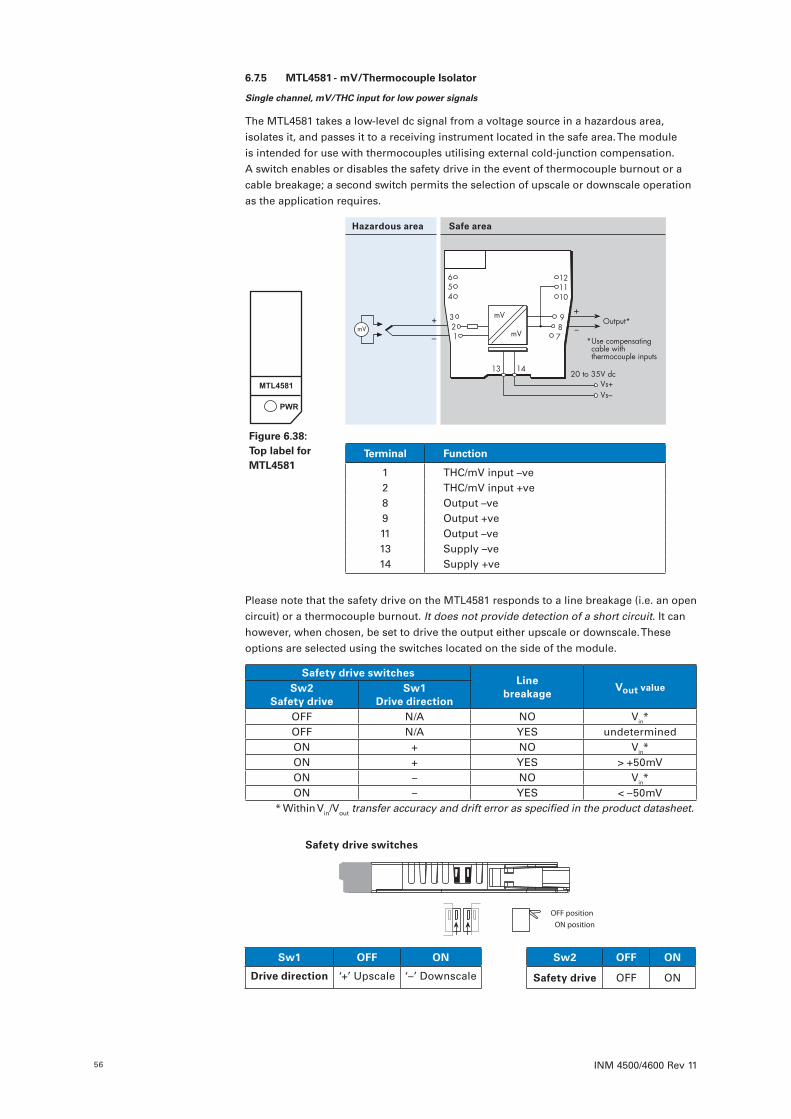
INM 4500/4600 Rev 1156
6 .7 .5 MTL4581 - mV/Thermocouple Isolator
Single channel, mV/THC input for low power signals
The MTL4581 takes a low-level dc signal from a voltage source in a hazardous area, isolates it, and passes it to a receiving instrument located in the safe area. The module is intended for use with thermocouples utilising external cold-junction compensation. A switch enables or disables the safety drive in the event of thermocouple burnout or a cable breakage; a second switch permits the selection of upscale or downscale operation as the application requires.
Please note that the safety drive on the MTL4581 responds to a line breakage (i.e. an open circuit) or a thermocouple burnout. It does not provide detection of a short circuit. It can however, when chosen, be set to drive the output either upscale or downscale. These options are selected using the switches located on the side of the module.
Safety drive switchesLine
breakageVout valueSw2
Safety driveSw1
Drive directionOFF N/A NO Vin*OFF N/A YES undeterminedON + NO Vin*ON + YES > +50mVON – NO Vin*ON – YES < –50mV
* Within Vin/Vout transfer accuracy and drift error as specified in the product datasheet.
Hazardous area Safe area
Output*
Vs–Vs+
20 to 35V dc
654
321
mV
mV
987
121110
13 14
mV
* Use compensating cable with thermocouple inputs
Terminal Function
1 THC/mV input –ve2 THC/mV input +ve8 Output –ve9 Output +ve11 Output –ve13 Supply –ve14 Supply +ve
Figure 6 .38: Top label for MTL4581
OFF positionON position
Sw 1 Sw 2
Safety drive switches
Sw1 OFF ON Sw2 OFF ON
Drive direction ‘+’ Upscale ‘–’ Downscale Safety drive OFF ON
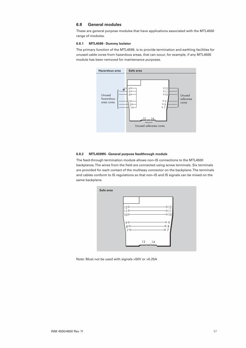
INM 4500/4600 Rev 11 57
6 .8 General modulesThese are general purpose modules that have applications associated with the MTL4500 range of modules.
6 .8 .1 MTL4599 - Dummy Isolator
The primary function of the MTL4599, is to provide termination and earthing facilities for unused cable cores from hazardous areas, that can occur, for example, if any MTL4500 module has been removed for maintenance purposes.
6 .8 .2 MTL4599N - General purpose feedthrough module
The feed-through termination module allows non–IS connections to the MTL4500 backplanes. The wires from the field are connected using screw terminals. Six terminals are provided for each contact of the multiway connector on the backplane. The terminals and cables conform to IS regulations so that non–IS and IS signals can be mixed on the same backplane.
Safe area
121110
987
13 14
987
121110
Note: Must not be used with signals >50V or >0.25A
Hazardous area Safe area
654
321
121110
987
Unused hazardous-area cores
Unused safe-area cores
Unused safe-area cores
13 14

INM 4500/4600 Rev 1158
6 .9 PCS45/PCL45USB configurator for MTL temperature converters
The PCS45/PCL45USB configurator allows MTL isolating temperature converters to be configured from a standard PC running a Microsoft® Windows® operating system. The configurator comprises PC software provided on a CD (PCS45), and an ATEX certified interfacing link (PCL45USB). Temperature converters can be configured from the safe area, while on-line, and the software allows configurations to be saved to disk and printed out when required.
It is suitable for use with MTL4000, MTL4500, MTL4600, MTL5000 and MTL5500 range of products.
PCL45USB hardware
The PCL45USB provides the interfacing link between the converter module and the PC running the software and connects to the PC using the USB cable provided. The PCL45USB has a built-in cable fitted with a 3.5mm jackplug to connect to the ‘Config’ socket on MTL4500 and MTL5500 range of converters. An adapter cable is also provided to accommodate our earlier converters.
PCS45 Configuration software
The software provided on the CD requires only approximately 20Mb of hard disk space and is compatible with Windows 2000, Windows XP or Windows 7. Ensure that the chosen PC has a CD ROM drive and an available USB port. A local or network printer may also be an advantage.
SafetyIt is not permitted to connect the PCL45USB to any device other than one approved by Eaton. Authorisation is valid provided that the converter type is named on the PCL45USB certificate or if the PCL45USB is specified on the converter certificate. Repairs to the PCL45USB are not permitted.
Setting upThe equipment can be used only in the safe area.
Before plugging in the PCL45USB link to the computer, extract the USB driver files to a known location on your PC. Afterwards, plug in the PCL45USB to the USB port on the PC and wait for it to find the new device. When requested by the computer, show it the location of the driver files so that it can complete the device installation.
Place the PCS45 software CD in the computer’s CDROM drive and follow the on-screen instructions to install the software.
The PCL45USB is powered from the data lines and quickly establishes communication after plugging the 3.5mm connector to the device socket.
Note: Ensure that the 3.5mm jack plug is fully inserted into the socket of the temperature converter.
The software and its operations manual (INM PCS45) is available on-line at: http://www.mtl-inst.com/product/configuration_tools_and_software/
Safe area

INM 4500/4600 Rev 11 59
7 FAULT FINDING AND ROUTINE MAINTENANCE
WARNING!
On removal, take care that a hazardous-area connector is not laid in a position
in which it may inadvertently come into contact with the backplane or with
components on the backplane.
7 .1 Maintenance precautionsMost Codes of Practice for intrinsic safety permit live maintenance on intrinsically safe devices and systems, provided precautions are taken to preserve the integrity of the device or system. During live maintenance of MTL4500 modules, the hazardous-area connectors that plug into the tops of the modules are likely to be removed. Avoid leaving a hazardous-area connector in a position where it may inadvertently contact non-IS circuits that are nearby. Prevent this by providing some form of temporary mechanical method of securing the connector so that it cannot come into contact with the non-IS circuits:
d) By plugging the connector into an MTL4599 dummy isolator
e) By using a tiewrap to constrain the connector in a safe position.
7 .2 Fault findingWhen fault finding, carry out the following steps as far as is necessary:–
7 .2 .1
Check that one of the backplane power LEDs is ON.
7 .2 .2
If a power LED is not on, check the power supply fuse and if necessary, change it. Ratings are:–
f) 4/8-way backplanes 1A (Spare fuse kit FUS1.0ATE5)
g) 16-way backplanes 2A (Spare fuse kit FUS2.0ATE5)
h) 24/32-way backplanes 4A (Spare fuse kit FUS4.0ATE5)
7 .2 .3
Check that all modules with power (PWR) LEDs are ON.
With the MTL4532, MTLx573, MTL4575 & MTL4576 models, a flashing LED indicates alarm or fault conditions - refer to section 8. Note: The LED may also flash during intermediate stages of configuration.
7 .2 .4
Exchange potentially faulty modules for working units as follows:–
a) Unplug the hazardous-area connectors.
b) Unplug the module from the backplane.
c) Plug the replacement unit into the backplane.
d) Replace the hazardous-area connectors.
7 .2 .5
Potentially faulty modules should be tested in workshop conditions, using the following procedure:–
a) Connect a power supply to a spare CPS backplane (refer to sections 4.4.2 or 4.4.4).
b) Plug the suspect module into any position on the backplane.
c) Carry out the appropriate test procedure described in Section 8 for the particular module.
7 .3 Routine maintenanceCheck the general condition of the installation occasionally to make sure that no deterioration has occurred. Carry out the following at least once every two years and more frequently for particularly harsh environments:–
a) Check that modules are of the types specified in the relevant documentation and that they are mounted in the correct positions on the associated backplanes.
b) Check that modules and hazardous-area connectors are correctly and legibly tagged, that the connectors are plugged into the matching modules and that the tag details given comply with the relevant documentation.

INM 4500/4600 Rev 1160
c) Check that modules and hazardous-area connectors are securely plugged into their matching sockets.
d) Check that all connections to the backplane and to the hazardous-area connectors are properly made.
e) Check that connecting cables to backplanes and to hazardous-area connectors are of the specified type and rating, are correctly routed and segregated (particularly in Eaton enclosures), and are not frayed or otherwise damaged.
f) Check that cable screens are properly earthed.
Note: It is strongly recommended that only the tests (described in Section 8) and routine maintenance (described here) should be undertaken by users. If a module is faulty, DO NOT attempt to make repairs or modifications as these may affect the intrinsic safety of the module. All faulty units should be returned to the Eaton’s MTL product line or representative from which they were purchased, for repair or replacement.
Any faulty backplanes supplied by us should also be similarly returned.
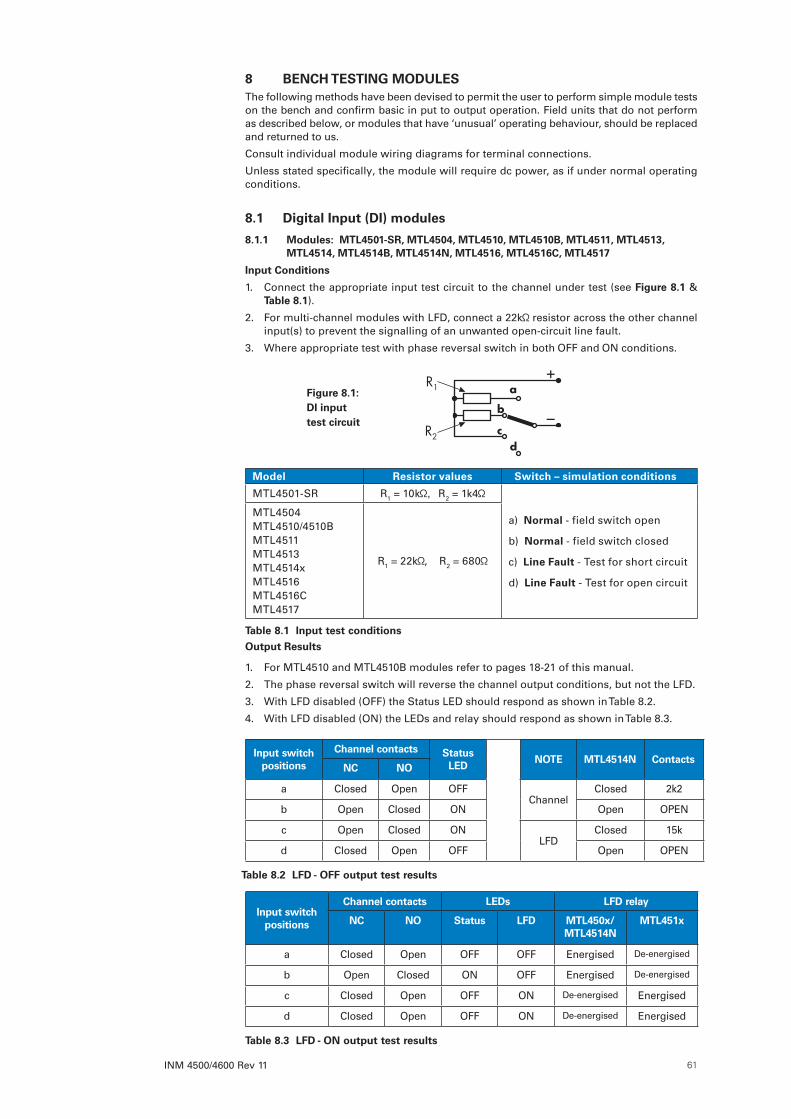
INM 4500/4600 Rev 11 61
8 BENCH TESTING MODULESThe following methods have been devised to permit the user to perform simple module tests on the bench and confirm basic in put to output operation. Field units that do not perform as described below, or modules that have ‘unusual’ operating behaviour, should be replaced and returned to us.
Consult individual module wiring diagrams for terminal connections.
Unless stated specifically, the module will require dc power, as if under normal operating conditions.
8 .1 Digital Input (DI) modules
8 .1 .1 Modules: MTL4501-SR, MTL4504, MTL4510, MTL4510B, MTL4511, MTL4513, MTL4514, MTL4514B, MTL4514N, MTL4516, MTL4516C, MTL4517
Input Conditions
1. Connect the appropriate input test circuit to the channel under test (see Figure 8 .1 & Table 8 .1).
2. For multi-channel modules with LFD, connect a 22k resistor across the other channel input(s) to prevent the signalling of an unwanted open-circuit line fault.
3. Where appropriate test with phase reversal switch in both OFF and ON conditions.
Model Resistor values Switch – simulation conditions
MTL4501-SR R1 = 10k R2 = 1k4
a) Normal - field switch open
b) Normal - field switch closed
c) Line Fault - Test for short circuit
d) Line Fault - Test for open circuit
MTL4504MTL4510/4510BMTL4511MTL4513MTL4514xMTL4516MTL4516CMTL4517
R1 = 22k , R2 = 680
Table 8 .1 Input test conditions
Output Results
1. For MTL4510 and MTL4510B modules refer to pages 18-21 of this manual.
2. The phase reversal switch will reverse the channel output conditions, but not the LFD.
3. With LFD disabled (OFF) the Status LED should respond as shown in Table 8.2.
4. With LFD disabled (ON) the LEDs and relay should respond as shown in Table 8.3.
Input switch positions
Channel contacts Status LED
NOTE MTL4514N ContactsNC NO
a Closed Open OFFChannel
Closed 2k2
b Open Closed ON Open OPEN
c Open Closed ONLFD
Closed 15k
d Closed Open OFF Open OPEN
Table 8 .2 LFD - OFF output test results
Input switch positions
Channel contacts LEDs LFD relay
NC NO Status LFD MTL450x/MTL4514N
MTL451x
a Closed Open OFF OFF Energised De-energised
b Open Closed ON OFF Energised De-energised
c Closed Open OFF ON De-energised Energised
d Closed Open OFF ON De-energised Energised
Table 8 .3 LFD - ON output test results
Figure 8 .1: DI input test circuit
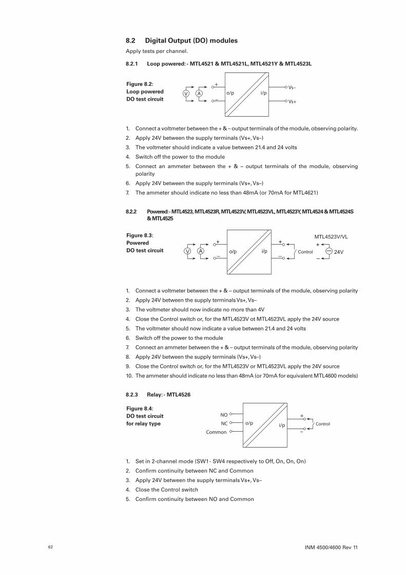
INM 4500/4600 Rev 1162
8 .2 Digital Output (DO) modulesApply tests per channel.
8 .2 .1 Loop powered: - MTL4521 & MTL4521L, MTL4521Y & MTL4523L
+
– Vs+
Vs–i/po/pV A
1. Connect a voltmeter between the + & – output terminals of the module, observing polarity.
2. Apply 24V between the supply terminals (Vs+, Vs–)
3. The voltmeter should indicate a value between 21.4 and 24 volts
4. Switch off the power to the module
5. Connect an ammeter between the + & – output terminals of the module, observing polarity
6. Apply 24V between the supply terminals (Vs+, Vs–)
7. The ammeter should indicate no less than 48mA (or 70mA for MTL4621)
8 .2 .2 Powered: - MTL4523, MTL4523R, MTL4523V, MTL4523VL, MTL4523Y, MTL4524 & MTL4524S & MTL4525
+
–Controli/po/pV A
+
–24V
+
–
MTL4523V/VL
1. Connect a voltmeter between the + & – output terminals of the module, observing polarity
2. Apply 24V between the supply terminals Vs+, Vs–
3. The voltmeter should now indicate no more than 4V
4. Close the Control switch or, for the MTL4523V ot MTL4523VL apply the 24V source
5. The voltmeter should now indicate a value between 21.4 and 24 volts
6. Switch off the power to the module
7. Connect an ammeter between the + & – output terminals of the module, observing polarity
8. Apply 24V between the supply terminals (Vs+, Vs–)
9. Close the Control switch or, for the MTL4523V or MTL4523VL apply the 24V source
10. The ammeter should indicate no less than 48mA (or 70mA for equivalent MTL4600 models)
8 .2 .3 Relay: - MTL4526
Controli/po/p+
–Common
NC
NO
1. Set in 2-channel mode (SW1 - SW4 respectively to Off, On, On, On)
2. Confirm continuity between NC and Common
3. Apply 24V between the supply terminals Vs+, Vs–
4. Close the Control switch
5. Confirm continuity between NO and Common
Figure 8 .2: Loop powered DO test circuit
Figure 8 .3: Powered DO test circuit
Figure 8 .4: DO test circuit for relay type
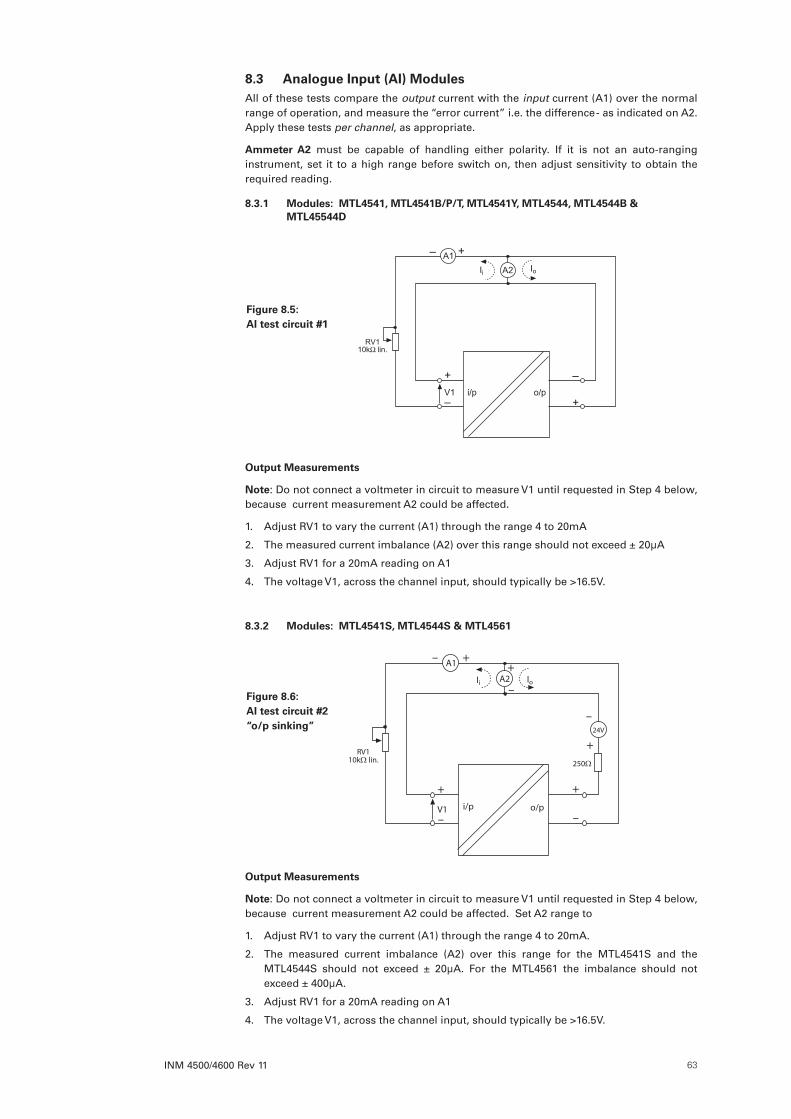
INM 4500/4600 Rev 11 63
8 .3 Analogue Input (AI) ModulesAll of these tests compare the output current with the input current (A1) over the normal range of operation, and measure the “error current” i.e. the difference - as indicated on A2. Apply these tests per channel, as appropriate.
Ammeter A2 must be capable of handling either polarity. If it is not an auto-ranging instrument, set it to a high range before switch on, then adjust sensitivity to obtain the required reading.
8 .3 .1 Modules: MTL4541, MTL4541B/P/T, MTL4541Y, MTL4544, MTL4544B & MTL45544D
Output Measurements
Note: Do not connect a voltmeter in circuit to measure V1 until requested in Step 4 below, because current measurement A2 could be affected.
1. Adjust RV1 to vary the current (A1) through the range 4 to 20mA
2. The measured current imbalance (A2) over this range should not exceed ± 20µA
3. Adjust RV1 for a 20mA reading on A1
4. The voltage V1, across the channel input, should typically be >16.5V.
8 .3 .2 Modules: MTL4541S, MTL4544S & MTL4561
+
–
+
–
+–
V1 i/p o/p
RV110kΩ lin.
A1
250Ω
24V
+
–
IoIi A2+
–
Output Measurements
Note: Do not connect a voltmeter in circuit to measure V1 until requested in Step 4 below, because current measurement A2 could be affected. Set A2 range to
1. Adjust RV1 to vary the current (A1) through the range 4 to 20mA.
2. The measured current imbalance (A2) over this range for the MTL4541S and the MTL4544S should not exceed ± 20µA. For the MTL4561 the imbalance should not exceed ± 400µA.
3. Adjust RV1 for a 20mA reading on A1
4. The voltage V1, across the channel input, should typically be >16.5V.
Figure 8 .5: AI test circuit #1
Figure 8 .6: AI test circuit #2 “o/p sinking”
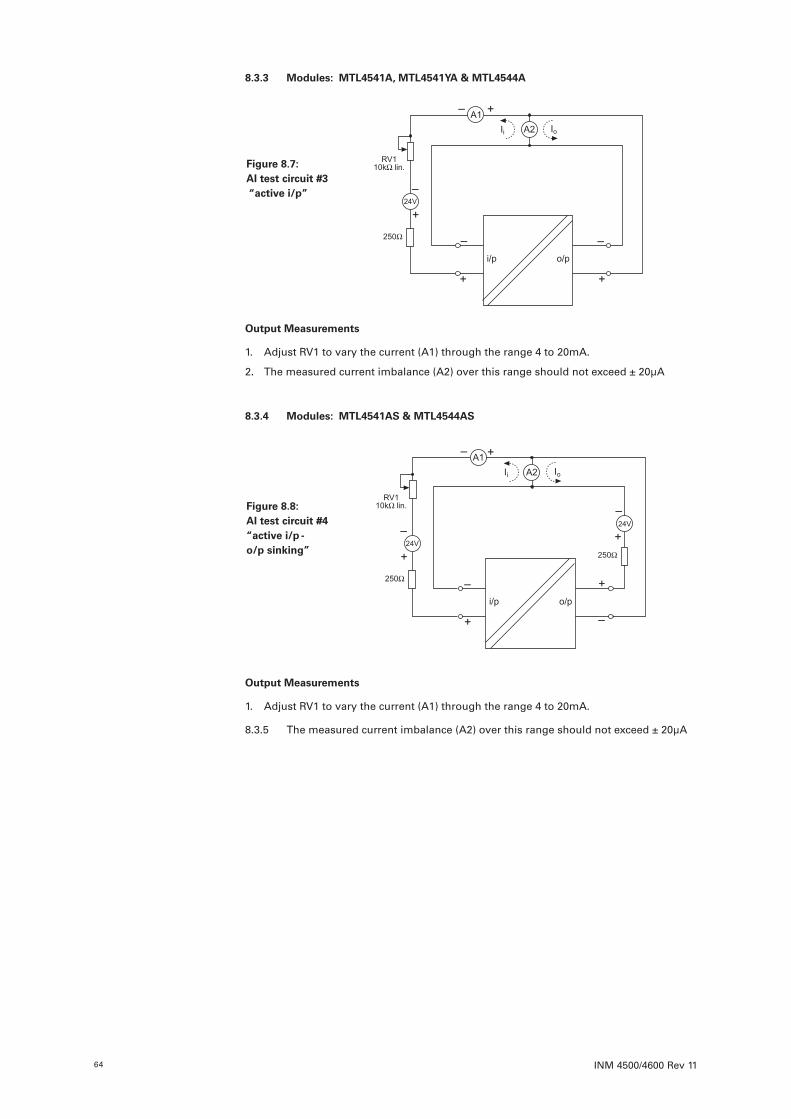
INM 4500/4600 Rev 1164
8 .3 .3 Modules: MTL4541A, MTL4541YA & MTL4544A
Output Measurements
1. Adjust RV1 to vary the current (A1) through the range 4 to 20mA.
2. The measured current imbalance (A2) over this range should not exceed ± 20µA
8 .3 .4 Modules: MTL4541AS & MTL4544AS
Output Measurements
1. Adjust RV1 to vary the current (A1) through the range 4 to 20mA.
8.3.5 The measured current imbalance (A2) over this range should not exceed ± 20µA
Figure 8 .7: AI test circuit #3 “active i/p”
Figure 8 .8: AI test circuit #4 “active i/p - o/p sinking”

INM 4500/4600 Rev 11 65
8 .3 .6 Module: MTL4581
Note: V1 should be capable of measurement to within 1µV.
Output Measurements
1. With the LINK connected, vary output V2 between 0 and 50mV using RV1. V1 should show <50µV variation. (Note: Safety Drive can be ON or OFF )
2. With the LINK disconnected and Safety Drive ON, V2 should drive to >+50mV with the switch set to ‘+’, or <–50mV with the switch set to ‘–’.
8 .4 Analogue Output (AO) ModulesThe test compares the output current with the input current over the normal range of operation.
8 .4 .1 Modules: All variants
Input Conditions
The chosen “load” resistor can be any value between 100 and 800 .
+
– +
–
A2
+
–
A1
o/p i/p
currentsource
+–
470Ω load
IoIi
Output Measurements
1. Adjust the current source to vary the current (A1) through the range 4 to 20mA.
2. The measured current imbalance (A2) over this range should not exceed ± 20µA.
8 .5 Testing the functioning of other modulesSimple tests to verify their basic operation can be devised for other modules (e.g. temperature, pulse, vibration, etc). If any assistance is required for the testing of a particular module, please contact the technical support department at Eaton for advice.
Figure 8 .9: AI test circuit #5 “mV input”
Figure 8 .10: AO test circuit

INM 4500/4600 Rev 1166
8 .5 .1 Testing
Make the safe- and hazardous-area connection shown in figure 8.12.
Figure 8 .11: Test circuit for MTL4531
Measure the voltage on terminal 3 with respect to terminal 1; this should be >19V. Vary the potentiometer setting and check that the reading on voltmeter V varies by no more than ±100mV.
9 APPLICATIONS INVOLVING ZONE 2 AND/OR ZONE 22 HAZARDOUS AREAS
IMPORTANT: See the front of this manual for important additional information regarding the use of these products in countries governed by the ATEX Directive.
The European Community permits Category 3G equipment, such as the MTL4500 range, to be installed in, or connected to, Zone 2 flammable atmospheres provided it meets the requirements of the ATEX Directive.
MTL4500 Category 3 products have been designed to meet, and carry approval markings for, Ex nC and/or Ex nA.
In general, meeting the relevant requirements of the appropriate European (CENELEC) standards is considered the most appropriate method of demonstrating compliance with the ATEX directive. However, Eaton often has its products approved by other national bodies, such as FM and CSA and, because national, European, and international standards are converging, it is generally possible to use other national approvals as supporting evidence for the ATEX Technical File.
In the context of this document, Zone 2 (Division 2) and Zone 22 hazardous areas are those that may become potentially explosive through the presence of flammable gases, vapours and dusts for periods of up to 10 hours per year. It is recommended that the current version of the standards is consulted for detailed information on the requirements applicable to the particular installation.
As a consequence of their IS approvals, MTL4500 products may also be connected into Zone 22 hazardous areas. Consult individual module approvals for further details.
Unless otherwise specified, the following ambient conditions apply:
Ambient Temperature range –20°C to +60°C
Pollution Degree 2 (See EN 61010-1)
Measurement Category II (See EN 61010-1)
9 .1 EnclosureEN 60079-15 specifies the minimum required degree of protection to be IP54, but generally this is provided by the external enclosure in which the product is mounted.
The user must refer to the specific certificates relating to the products being installed within the hazardous area to check that all special conditions of safe use have been complied with.
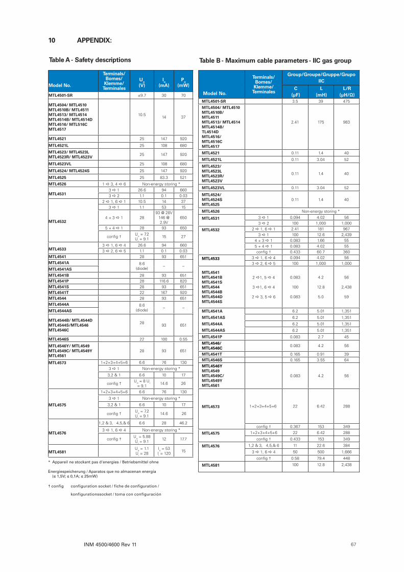
INM 4500/4600 Rev 11 67
Table A - Safety descriptions Table B - Maximum cable parameters - IIC gas group
Model No .
Terminals/ Bornes/
Klemme/ Terminales
Group/Groupe/Gruppe/Grupo IIC
C(µF)
L(mH)
L/R(µH/Ω)
MTL4501-SR 3.5 39 475
MTL4504/ MTL4510MTL4510B/ MTL4511MTL4513/ MTL4514MTL4514B/TL4514DMTL4516/ MTL4516CMTL4517
2.41 175 983
MTL4521 0.11 1.4 40
MTL4521L 0.11 3.04 52
MTL4523/ MTL4523LMTL4523R/MTL4523V
0.11 1.4 40
MTL4523VL 0.11 3.04 52
MTL4524/ MTL4524SMTL4525
0.11 1.4 40
MTL4526 Non-energy storing *
MTL4531 3 a 1 0.094 4.02 563 a 2 100 1,000 1,000
MTL4532 2 a 1, 6 a 1 2.41 181 9673 a 1 100 12.6 2,439
4 + 3 a 1 0.083 1.66 555 + 4 a 1 0.083 4.02 55config † 0.433 60.7 360
MTL4533 3 a 1, 6 a 4 0.094 4.02 563 a 2, 6 a 5 100 1,000 1,000
MTL4541MTL4541BMTL4541SMTL4544MTL4544BMTL4544DMTL4544S
2 a1, 5 a 4
3 a1, 6 a 4
2 a 3, 5 a 6
0.083
100
0.083
4.2
12.8
5.0
56
2,438
59
MTL4541A 6.2 5.01 1,351
MTL4541AS 6.2 5.01 1,351
MTL4544A 6.2 5.01 1,351
MTL4544AS 6.2 5.01 1,351
MTL4541P 0.083 2.7 45
MTL4546/MTL4546C 0.083 4.2 56
MTL4541T 0.165 0.91 39MTL4546S 0.165 3.55 64MTL4546Y/ MTL4549MTL4549C/MTL4549YMTL4561
0.083 4.2 56
MTL4573 1+2+3+4+5+6 22 6.42 288
config † 0.367 153 349
MTL4575 1+2+3+4+5+6 22 6.42 288
config † 0.433 153 349
MTL4576 1,2 & 3, 4,5,& 6 11 22.6 384
3 a 1, 6 a 4 50 500 1,666
config † 0.58 79.4 448
MTL4581 100 12.8 2,438
Model No .
Terminals/ Bornes/
Klemme/ Terminales
Uo(V)
Io(mA)
Po(mW)
MTL4501-SR ±9.7 30 70
MTL4504/ MTL4510MTL4510B/ MTL4511MTL4513/ MTL4514MTL4514B/ MTL4514DMTL4516/ MTL516CMTL4517
10.5 14 37
MTL4521 25 147 920
MTL4521L 25 108 680
MTL4523/ MTL4523LMTL4523R/ MTL4523V 25 147 920
MTL4523VL 25 108 680
MTL4524/ MTL4524S 25 147 920
MTL4525 25 83.3 521
MTL4526 1 a 3, 4 a 6 Non-energy storing *
MTL45313 a 1 26.6 94 6603 a 2 1.1 0.1 0.03
MTL4532
2 a 1, 6 a 1 10.5 14 373 a 1 1.1 53 15
4 + 3 a 1 2893 @ 28V
146 @ 2.9V
650
5 + 4 a 1 28 93 650
config † Uo = 7.2 Ui = 9.1 15 27
MTL45333 a 1, 6 a 4 26.6 94 6603 a 2, 6 a 5 1.1 0.1 0.03
MTL4541 28 93 651MTL4541A 8.6
(diode) – –MTL4541ASMTL4541B 28 93 651MTL4541P 28 116.6 820MTL4541S 28 93 651MTL4541T 22 167 920MTL4544 28 93 651MTL4544A 8.6
(diode) – –MTL4544AS
MTL4544B/ MTL4544DMTL4544S/MTL4546MTL4546C
28 93 651
MTL4546S 22 100 0.55
MTL4546Y/ MTL4549MTL4549C/ MTL4549YMTL4561
28 93 651
MTL4573 1+2+3+4+5+6 6.6 76 130
3 a 1 Non-energy storing *
3,2 & 1 6.6 10 17
config † Uo = 8 Ui = 9.1 14.6 26
MTL4575
1+2+3+4+5+6 6.6 76 130
3 a 1 Non-energy storing *
3,2 & 1 6.6 10 17
config † Uo = 7.2 Ui = 9.1 14.6 26
MTL4576
1,2 & 3, 4,5,& 6 6.6 28 46.2
3 a 1, 6 a 4 Non-energy storing *
config † Uo = 5.88 Ui = 9.1 12 17.7
MTL4581Uo = 1.1 Ui = 28
Io = 53 Ii = 120 15
* Appareil ne stockant pas d'energies / Betriebsmittel ohne
Energiespeicherung / Aparatos que no almacenan energía (≤ 1,5V; ≤ 0,1A; ≤ 25mW)
† config configuration socket / fiche de configuration /
konfigurationssocket / toma con configuración
10 APPENDIX:

EUROPE (EMEA):
+44 (0)1582 723633 [email protected]
THE AMERICAS:
+1 800 835 7075 [email protected]
ASIA-PACIFIC:
+65 6 645 9888 [email protected]
The given data is only intended as a product description and should not be regarded as a legal warranty of properties or guarantee. In the interest of further technical developments, we reserve the right to make design changes.
Eaton Electric Limited, Great Marlings, Butterfield, LutonBeds, LU2 8DL, UK.Tel: + 44 (0)1582 723633 Fax: + 44 (0)1582 422283E-mail: [email protected]
© 2017 Eaton All Rights ReservedPublication No. INM 4500/4600 Rev11 120117January 2017
AUSTRALIAMTL Instruments Pty Ltd, 10 Kent Road, Mascot, New South Wales, 2020, Australia
Tel: +61 1300 308 374 Fax: +61 1300 308 463E-mail: [email protected]
BeNeLuxMTL Instruments BVAmbacht 6, 5301 KW ZaltbommelThe Netherlands
Tel: +31 (0)418 570290 Fax: +31 (0)418 541044E-mail: [email protected]
CHINACooper Electric (Shanghai) Co. Ltd955 Shengli Road, Heqing Industrial ParkPudong New Area, Shanghai 201201
Tel: +86 21 2899 3817 Fax: +86 21 2899 3992E-mail: [email protected]
FRANCEMTL Instruments sarl,7 rue des Rosiéristes, 69410 Champagne au Mont d’OrFrance
Tel: +33 (0)4 37 46 16 53 Fax: +33 (0)4 37 46 17 20E-mail: [email protected]
GERMANYMTL Instruments GmbH, Heinrich-Hertz-Str. 12, 50170 Kerpen, Germany
Tel: +49 (0)22 73 98 12 - 0 Fax: +49 (0)22 73 98 12 - 2 00E-mail: [email protected]
INDIAMTL India, No.36, Nehru Street, Off Old Mahabalipuram RoadSholinganallur, Chennai - 600 119, India
Tel: +91 (0) 44 24501660 /24501857 Fax: +91 (0) 44 24501463E-mail: [email protected]
ITALYMTL Italia srl, Via San Bovio, 3, 20090 Segrate, Milano, Italy
Tel: +39 02 959501 Fax: +39 02 95950759E-mail: [email protected]
JAPANCooper Crouse-Hinds Japan KK, MT Building 3F, 2-7-5 Shiba Daimon, Minato-ku,Tokyo, Japan 105-0012
Tel: +81 (0)3 6430 3128 Fax: +81 (0)3 6430 3129E-mail: [email protected]
NORWAYNorex ASFekjan 7c, Postboks 147, N-1378 Nesbru, Norway
Tel: +47 66 77 43 80 Fax: +47 66 84 55 33E-mail: [email protected]
RUSSIACooper Industries Russia LLCElektrozavodskaya Str 33Building 4Moscow 107076, Russia
Tel: +7 (495) 981 3770 Fax: +7 (495) 981 3771E-mail: [email protected]
SINGAPORECooper Crouse-Hinds Pte LtdNo 2 Serangoon North Avenue 5, #06-01 Fu Yu BuildingSingapore 554911
Tel: +65 6645 9864 / 6645 9865 Fax: +65 6 487 7997E-mail: [email protected]
SOUTH KOREACooper Crouse-Hinds Korea7F. Parkland Building 237-11 Nonhyun-dong Gangnam-gu,Seoul 135-546, South Korea.
Tel: +82 6380 4805 Fax: +82 6380 4839E-mail: [email protected]
UNITED ARAB EMIRATESCooper Industries/Eaton Corporation Office 205/206, 2nd Floor SJ Towers, off. Old Airport Road, Abu Dhabi, United Arab Emirates
Tel: +971 2 44 66 840 Fax: +971 2 44 66 841E-mail: [email protected]
UNITED KINGDOMEaton Electric Ltd, Great Marlings, Butterfield, LutonBeds LU2 8DL
Tel: +44 (0)1582 723633 Fax: +44 (0)1582 422283E-mail: [email protected]
AMERICASCooper Crouse-Hinds MTL Inc. 3413 N. Sam Houston Parkway W.Suite 200, Houston TX 77086, USA
Tel: +1 281-571-8065 Fax: +1 281-571-8069E-mail: [email protected]