iso4401 size 05; dgm**-5 30 design - eatonpub/@eaton/@hyd/... · n-2 eaton dm design evstbbe april...
TRANSCRIPT

DGM**-5 30 DesignISO4401 Size 05; ANSI/B93.7M-D05
EATON DGM**-5 30 Design E-VLST-BB002-E April 2015N-2
N
SystemStak™ ValvesISO4401 Size 05
General Description
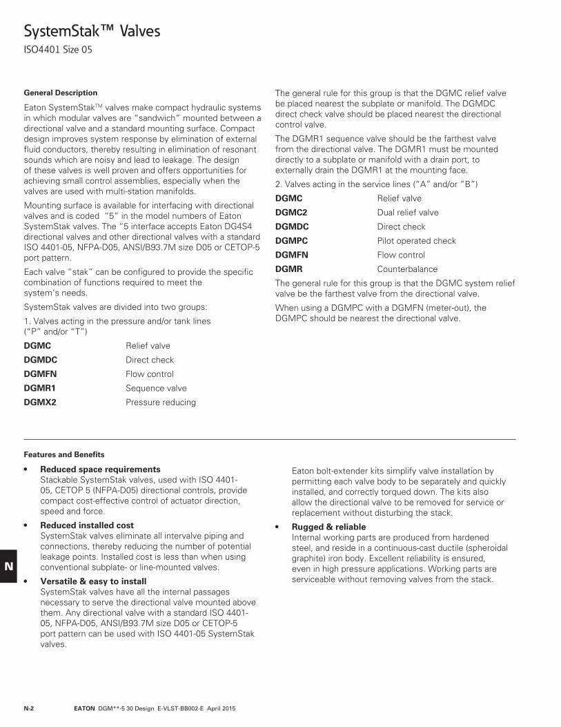
Eaton SystemStakTM valves make compact hydraulic systems in which modular valves are “sandwich” mounted between a directional valve and a standard mounting surface. Compact design improves system response by elimination of external fluid conductors, thereby resulting in elimination of resonant sounds which are noisy and lead to leakage. The design of these valves is well proven and offers opportunities for achieving small control assemblies, especially when the valves are used with multi-station manifolds.
Mounting surface is available for interfacing with directional valves and is coded “5” in the model numbers of Eaton SystemStak valves. The “5 interface accepts Eaton DG4S4 directional valves and other directional valves with a standard ISO 4401-05, NFPA-D05, ANSI/B93.7M size D05 or CETOP-5 port pattern.
Each valve “stak” can be configured to provide the specific combination of functions required to meet the system’s needs.
SystemStak valves are divided into two groups:
1. Valves acting in the pressure and/or tank lines (“P” and/or “T”)
DGMC Relief valve
DGMDC Direct check
DGMFN Flow control
DGMR1 Sequence valve
DGMX2 Pressure reducing
The general rule for this group is that the DGMC relief valve be placed nearest the subplate or manifold. The DGMDC direct check valve should be placed nearest the directional control valve.
The DGMR1 sequence valve should be the farthest valve from the directional valve. The DGMR1 must be mounted directly to a subplate or manifold with a drain port, to externally drain the DGMR1 at the mounting face.
2. Valves acting in the service lines (“A” and/or “B”)
DGMC Relief valve
DGMC2 Dual relief valve
DGMDC Direct check
DGMPC Pilot operated check
DGMFN Flow control
DGMR Counterbalance
The general rule for this group is that the DGMC system relief valve be the farthest valve from the directional valve.
When using a DGMPC with a DGMFN (meter-out), the DGMPC should be nearest the directional valve.
Features and Benefits
• Reduced space requirements Stackable SystemStak valves, used with ISO 4401-05, CETOP 5 (NFPA-D05) directional controls, provide compact cost-effective control of actuator direction, speed and force.
• Reduced installed cost SystemStak valves eliminate all intervalve piping and connections, thereby reducing the number of potential leakage points. Installed cost is less than when using conventional subplate- or line-mounted valves.
• Versatile & easy to install SystemStak valves have all the internal passages necessary to serve the directional valve mounted above them. Any directional valve with a standard ISO 4401-05, NFPA-D05, ANSI/B93.7M size D05 or CETOP-5 port pattern can be used with ISO 4401-05 SystemStak valves.
Eaton bolt-extender kits simplify valve installation by permitting each valve body to be separately and quickly installed, and correctly torqued down. The kits also allow the directional valve to be removed for service or replacement without disturbing the stack.
• Rugged & reliable Internal working parts are produced from hardened steel, and reside in a continuous-cast ductile (spheroidal graphite) iron body. Excellent reliability is ensured, even in high pressure applications. Working parts are serviceable without removing valves from the stack.

EATON DGM**-5 30 Design E-VLST-BB002-E April 2015 N-3
N
Easy to Understand, Easy to Design
SystemStak circuitry is best shown using slightly different symbols than those for traditional valve configurations. Each SystemStak symbol has the same basic form and size as shown in Figure 1.
For ease of understanding, remember the directions of flow for each line, and that all four flow paths pass through each valve (see Figure 2). For clarity, directional valves are drawn vertically in SystemStak circuit diagrams (see Figure 3.)
Each station (valve stack) is a combination of functions. When designing and assembling SystemStak valves, care must be taken to ensure that they interact as required by stacking the functions in the correct sequence (see Figure 4). Direct check valves should be placed closest to the directional valve. Relief valves should normally be positioned next to the mounting surface (i.e. at the bottom of the stack). When both a flow control and a pilot operated check valve is required, it is recommended that the flow control valve be between the check valve and the actuator to prevent check valve chatter.
A combination of directional valve, SystemStak valve(s) and subplate/ manifold block (Figure 5 single station subplate and Figure 6 multi station manifold) completes the assembly.
Figure 7 represents a complete SystemStak system, showing typical use of functions available from this range. The circuit diagram also shows the use of a tapping plate for accessing line pressure readings, and a blanking plate to close off an unused station of a multi-station manifold.
P T B A
Figure 1.
P T B A
Figure 2.
P T B A
Figure 3.
P T B A
DGMFN-5–Y-A-B-30
DGMPC-5-AB-BA-30
DGMC-5-PT-30
Figure 4.
Figure 5.
Figure 6.
Figure 7.
P
T
B A
P
T
B AB A
P
T
B AB AB A
DGMC-5-PT-30
DGMC-5-BA-30
DGMX2-5-PP-30
DGMX2-5-PA-30
DGMPC-5-AB-BA-30
DGMFN-5-Y-A-B-30
Blanking plate

EATON DGM**-5 30 Design E-VLST-BB002-E April 2015N-4
N
Table of Contents
Function Basic symbol Basic model Features Page
Relief DGMC/DCMC2 Single, dual and crossport 5 models
Reducing/relieving DGMX2 Piloted from (and reduced 13 pressure in) port P, A or B
Sequence DGMR1 Single port P sequence 17
Counterbalance DGMR Control in port T 20
Flow Control DGMFN Single or dual port, meter-in 24 or meter-out
Pilot operated check DGMPC Single in port A or B; dual 29 in ports A and B
Direct check DGMDC Single check in any port; dual 32 check in ports A and B only

EATON DGM**-5 30 Design E-VLST-BB002-E April 2015 N-5
N
SystemStak™ Pilot Operated Relief Valves
DGMC/DGMC2 General Description
These two-stage valves limit system pressure by directing flow to tank or the opposite cylinder port (A-B/B-A crossport types) when system pressure reaches the valve setting.
Pressure control may be obtained in “A”, “B”, “A” and “B”, or “P” port, and pilot flow may be internally or externally drained, depending on model type. Any pressure in the line to which these valves are drained is additive to the valve pres-sure setting.
The valve pressure setting is adjustable by means of either an adjusting screw and locknut, a hand-knob adjuster, or a micrometer knob with keylock. External remote control/vent connections are available on all models except crossport relief. If required on crossport models, contact your Eaton representative.
Model Code
1
2
3
4
5
6
7
8
9
10
11
12
13
14
15
16
Valve function
Manifold or subplate mounted pressure relief valve.
Valve type
2 – Dual relief cavitiesBlank – Single relief
Interface
5 – ISO 4401-AC-05-4-A, CETOP RP35H ANSI/NFPA D05
Port operated upon
A – “A” cylinder port (single, dual or crossport types)
B – “B” cylinder port (single type only)P – Pressure port (single type only)
Port drained into
A – “A” cylinder portB – “B” cylinder port (crossport type
only)T – Tank port (single or dual types)
Pressure range
A – 4 to 50 bar (60 to 725 psi)B – 4 to 100 bar (60 to 1450 psi)F – 4 to 200 bar (60 to 2900 psi)G – 4 to 315 bar (60 to 4500 psi)
Adjustment device
H – Knob adjusterK – Micrometer knob with keylockW – Screw with locknut
External drain
E – External drainOmit for internal drain models.
P port acted upon
B – “B” cylinder port (dual or crossport type) Omit for single type.
Port drained into
A – “A” cylinder port (crossport type only)
T – Tank port (dual type only)
Pressure range
Omit for single type.A – 4 to 50 bar (60 to 725 psi)B – 4 to 100 bar (60 to 1450 psi)F – 4 to 200 bar (60 to 2900 psi)G – 4 to 315 bar (60 to 4500 psi)
Adjustment deviceOmit for single relief models.H – Knob adjusterK – Micrometer knob with keylockW – Screw with locknut
External drain
E – External drain same as position 8 Omit for single relief models.
Remote control port
RC – Remote control portNot available on crossport models.
Gage port & thread type
Gage port for P-T models only; optional remote control (RC) and external drain (E) ports as applicable. Omit for crossport modelsB – G 1/8” (1/8” BSPF)S – SAE-4 O-ring boss port
(0.4375-20 UNF-2B thread)
Design number - 30 series
Subject to change. Installation dimensions unaltered for design numbers 30 to 39 inclusive.
DGMC - (2) - 5 - * * - * * - (E) - (B) (A) - * * - (E) - (RC) - (*) - 30
1 8 9 10 13 14 15 164 5 6 7 11 122 3

EATON DGM**-5 30 Design E-VLST-BB002-E April 2015N-6
N
Functional Symbols
P
P
T B
T B
TA
TA
B
B
A
A
DGMC2-5-AT-**-BT-**-*-30
P
P
T B
T B
TA
TA
B
B
A
A
DGMC2-5-AT-**-BT-**RC -*-30
P
P
T B
T B
TA
TA
B
B
A
A
DGMC2-5-AT-**-E-BT-**-E-*-30
P
P
T B
T B
TA
TA
B
B
A
A
DGMC2-5-AT-**-E-BT-**-E-RC -*-30
P
P
T B
T B
TA
TA
B
B
A
A
DGMC-5-AT-**-E-*-30
P
P
T B
T B
TA
TA
B
B
A
A
DGMC-5-AT-**-E-RC -*-30
P
P
T B
T B
TA
TA
B
B
A
A
DGMC-5-PT-**-*-30
P
P
T B
T B
TA
TA
B
B
A
A
DGMC-5-PT-**-RC -*-30
P
P
T B
T B
TA
TA
B
B
A
A
DGMC-5-PT-**-E-*-30P
P
T B
T B
TA
TA
B
B
A
A
DGMC2-5-AB-**-BA-**-30
P
P
T B
T B
TA
TA
B
B
A
A
DGMC-5-AT-**-*-30
P
P
T B
T B
TA
TA
B
B
A
A
DGMC-5-AT-**-RC -*-30
P
P
T B
T B
TA
TA
B
B
A
A
DGMC-5-BT-**-*-30
P
P
T B
T B
TA
TA
B
B
A
A
DGMC-5-BT-**-E-*-30
P
P
T B
T B
TA
TA
B
B
A
A
DGMC-5-BT-**-E-RC -*-30
DR
DR
RC
DR
RC
DR
RC
G
RC
G
DR
G
RC
RC
DR
RC
DR
RC
DR
DR
P
P
T B
T B
TA
TA
B
B
A
A
DGMC-5-PT-**-E-RC -*-30P
P
T B
T B
TA
TA
B
B
A
A
DGMC-5-BT-**-RC -*-30P
P
T B
T B
TA
TA
B
B
A
A
DGMC2-5-AB-**-E-BA-**-E-*-30
DRRC
DRG
RC
DR

EATON DGM**-5 30 Design E-VLST-BB002-E April 2015 N-7
N
Basic Characteristics
Maximum flow 120 l/min (32 USgpm)
Pilot flow@ 50°C (120°F) and 315 bar (4500 psi) 400–700 ml/min (24 in3/min-43 in3/min)
Maximum operating pressure 315 bar (4500 psi)ar (450 psi)Pressure overshoot 31 bar (450 psi) Operating temperature -0° to 80°C (32° to 180°F)Weights DGMC 2,9 kg (6.5 lbs) DGMC2 3,6 kg (7.9 lbs)
Response time: For conditions of 5 liters (300 in3) of oil under compression and a flow rate of 120 l/min (32 USgpm) typical response is: Initial pressure Final pressure Response time
17 bar (250 psi) 35 bar (500 psi) 95 ms 35 bar (500 psi) 140 bar (2000 psi) 110 ms 35 bar (500 psi) 315 bar (4500 psi) 150 ms
Operating Data
Performance DataDGMC-5 and DGMC2-5 Insertion Loss Insertion Loss
Total change in pressure drop from through ports “P” “B”, “A” and “T”caused by the addition of the SystemStak valve to a hydraulic circuit. Insertion loss curves (see top left):
1. DGMC2-5-AT-**-(E)-BT-**-(E)-(RC)*-30 DGMC-5-AT-**-(E)-(RC)*-30 DGMC-5-BT-**-(E)(RC)-*-30
2. DGMC-5-PT-**-(E)-(RC)*-30
3. DGMC2-5-AB-**-BA-**-30
DGMC-5 and DGMC2-5 Vented Pressure (RC models only)(Not applicable for crossport models)
DGMC-5 and DGMC2-5 Pressure Override
The pressure override chart (below) shows typical override of different adjustment ranges at maximum settings.
The vented pressure chart (above) indicates flow from control port to discharge port over relief element.
Pres
sure
Dro
p ba
r
Pres
sure
Dro
p ps
i
15
10
5
200
150
100
50
00
Flow l/min
Flow USgpm
20 40 60 80 100 120
5 10 15 20 25 30
1
2
3
Pres
sure
bar
Pres
sure
psi
20
15
10
250
200
150
100
00
Flow l/min
Flow USgpm
20 40 60 80 100 120
5 10 15 20 25 30
550
Pres
sure
psi Pr
essu
re b
ar
Pres
sure
psi200
150
100
4000
3000
2000
0 0
Flow l/min
Flow USgpm
20 40 60 80 100 120
5 10 15 20 25 30
501000
300
350
250
5000G
F
B
A
Override at minimum (“P”) setting all models

EATON DGM**-5 30 Design E-VLST-BB002-E April 2015N-8
N
14 (0.55)
50(1.97)
25(.98)
48(1.89)
“W” models (max. ext.)
Wrench size13 (1/2”)
11,5(0.45)
ISO 4401-AC-05-4-A (NFPA D05)Mounting surface
13,5 (0.53)
4 mounting holes 6,90 (0.27) through 9,50 (0.37) counterbore
36,5 (1.44) deep for bolt extenders (order separately)BKE-6M-50M (M6 metric) or BKE-4-50M (.2500-20 UNC).Torque: 11,3-14,7 Nm (100-130 lb. in.)
144,1 (5.67) max.
23(0.91)
50(1.97)
11,7(0.46)
33,2(1.31)
69,5(2.74)
71,6(2.82)max.
38(1.5)
11,8(0.46)
1,8(0.46) Adjust clockwise to increase pressure
setting.
External drain port. External connection port thread (see table)
External drain port. Plugged for internal drain.External connection portthread type (see table)
Remote control port.(“ RC” models only)External connection portthread type (see table)
Hex key4 (5/32”)
Gage port. External connectionport thread type: (see table)
T B
B
P
A
TA
3rd angleprojection
Installation Dimensions
DGMC-5-PT Single Relief mm (inches)
See page 37 for optional adjustment devices. See page 38 for interface dimensions.
External connection port threads
“S” models - SAE-4 O-ring boss port (0.4375-20 UNF-2B thread).
“B” models - G 1/8 (1/8 BSPF)
Note: Back pressure in drain is added to this setting for internal drain models only.

EATON DGM**-5 30 Design E-VLST-BB002-E April 2015 N-9
N
ISO 4401-AC-05-4-A (NFPA D05) Mounting surface
4 mounting holes (See page 8 forspecifications)
Adjust pressure “A” port. Adjust clockwise to increase pressure setting.
50(1.97)
30(1.18)
48 (1.89)“W” models (max. ext.)
Wrench sizeISO 4401-AC-05-4-A (NFPA D05)Mounting surface
13,5 (0.53)
141 (5.55)37 (1.46)11,7 (0.46)
33,2(1.31)
69,5(2.74)
71,6(2.82)max.
Adjust pressure “B” port. Adjust clockwise to increase pressure setting.
External drain port *Plugged for internal drain.
Remote control port. *(“ RC” models only)
Hex key
TA
B
P
A
T B
11,5(0.45)
15,3(0.60)
11,5(0.45)
12,5 (0.49)
50(1.97)
30(1.18)
48 (1.89) “W” models (max. ext.)
Wrench size13,5 (0.53)
4 mounting holes (See page 8 for specifications)
141 (5.55)50 (1.97) 11,7 (0.46)
33,2(1.31)
69,5(2.74)
71,6(2.82)max.
External drain port *Remote control port * (“RC ” models only)
Hex key
T B
B
P
A
TA
11,5(0.45)
11,5(0.45)
12,5(0.49)
External drain port *. Plugged for internal drain.
4 (5/32”)
13 (1/2”)
13 (1/2 ”)
4 (5/32”)
15,3 (0.60)
Installation Dimensions
DGMC-5-BT Single Relief mm (inches)
See page 37 for optional adjustment devices. See page 38 for interface dimensions.
* External connection port thread type: “S” models - SAE-4 O-ring boss port (0.4375-20 UNF-2B thread).
“B” models - G 1/8 (1/8 BSPF)
DGMC-5-AT Single Relief
• Back pressure in drain is added to this setting for internal drain models only.
EATON DGM**-5 30 Design E-VLST-BB002-E April 2015N-10
N
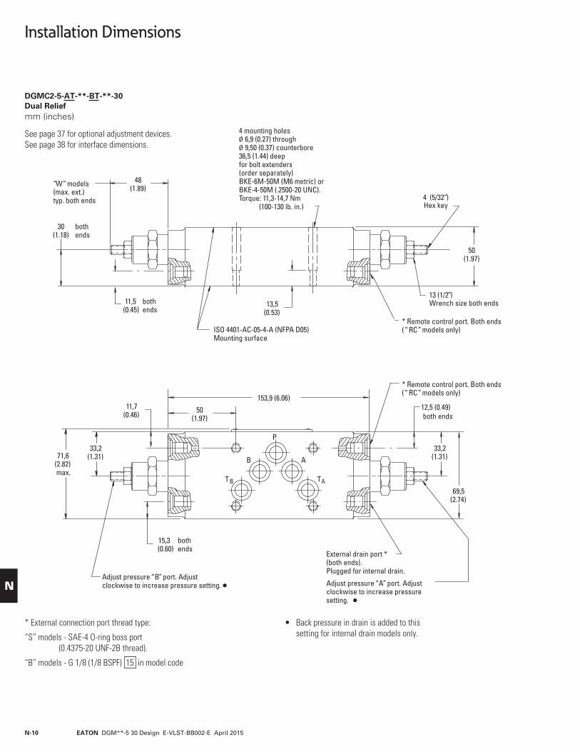
DGMC2-5-AT-**-BT-**-30 Dual Relief mm (inches)
See page 37 for optional adjustment devices. See page 38 for interface dimensions.
• Back pressure in drain is added to this setting for internal drain models only.
* Remote control port. Both ends(“ RC” models only)
50(1.97)
30(1.18)
48(1.89)
“W” models (max. ext.)typ. both ends
ISO 4401-AC-05-4-A (NFPA D05)Mounting surface
13,5(0.53)
153,9 (6.06)
50(1.97)
11,7(0.46)
33,2(1.31)71,6
(2.82)max.
Adjust pressure “B” port. Adjust clockwise to increase pressure setting.
TA
B
P
A
T B
Wrench size both ends
33,2(1.31)
69,5(2.74)
15,3(0.60)
bothends
11,5(0.45)
bothends
bothends
12,5 (0.49)both ends
Hex key
External drain port *(both ends).Plugged for internal drain.
Adjust pressure “A” port. Adjustclockwise to increase pressuresetting.
13 (1/2”)
4 (5/32”)
4 mounting holes 6,9 (0.27) through 9,50 (0.37) counterbore
36,5 (1.44) deep for bolt extenders(order separately)BKE-6M-50M (M6 metric) orBKE-4-50M (.2500-20 UNC).Torque: 11,3-14,7 Nm (100-130 lb. in.)
* Remote control port. Both ends(“ RC” models only)
* External connection port thread type:
“S” models - SAE-4 O-ring boss port (0.4375-20 UNF-2B thread).
“B” models - G 1/8 (1/8 BSPF) 15 in model code
Installation Dimensions

EATON DGM**-5 30 Design E-VLST-BB002-E April 2015 N-11
N
DGMC2-5-AB-**-BA-**-30 Dual Crossport Relief mm (inches)
See page 37 for optional adjustment devices. See page 38 for interface dimensions.
External drain port threads
“S” models - SAE-4 O-ring boss port (0.4375-20 UNF-2B thread).
“B” models - G 1/8 (1/8 BSPF)
60(2.36)
20(0.79)
45,6(1.71)
“W” models (max. ext.)typ. both ends
ISO 4401-AC-05-4-A (NFPA D05)Mounting surface
14,0 (0.55)
128 (5.04)37
(1.46)11,7
(0.46)
31,3(1.23)71,6
(2.82)max.
Adjust pressure “A” port. Adjust clockwise to increase pressure setting.
TA
B
P
A
T B
Wrench sizeboth ends
69,5(2.74)
Hex key
Adjust pressure “B” port. Adjustclockwise to increase pressure setting.
40(1.57)
4 mounting holes 6,90 (0.27) through. 9,50 (0.37) counterbore
46,5 (1.83) deep for bolt extenders(order separately)BKE-6M-60M (M6 metric) orBKE-4-60M (.2500-20 UNC). Torque: 11,3-14,7 Nm (100-130 lb. in.)
13 (1/2”)
4 (5/32”)
46(1.81)
External drain (See table)
External drain (See table)
B A
Installation Dimensions

EATON DGM**-5 30 Design E-VLST-BB002-E April 2015N-12
N
DGMC-5-AB-**-(E)-*-30 Single Crossport Relief mm (inches)
See page 37 for optional adjustment devices. See page 38 for interface dimensions.
60(2.36)
20(0.79)
45,6(1.71)
“W” models (max. ext.)
40(1.57)
60(2.36) 40
(1.57)
45,6(1.71)
“W” models (max. ext.)
40(1.57)
B A
B A
10,2 (0.40)
10,2 (0.40)
128 (5.04)
128 (5.04)
4 mounting holes (See above forspecifications)
4 mounting holes 6,90 (0.27) through. 9,50 (0.37) counterbore
46,5 (1.83) deep for bolt extenders(order separately)BKE-6M-60M (M6 metric) orBKE-4-60M (.2500-20 UNC). Torque: 11,3-14,7 Nm (100-130 lb. in.)
ISO 4401-AC-05-4-A (NFPA D05)Mounting surface
ISO 4401-AC-05-4-A (NFPA D05)Mounting surface
Installation Dimensions
DGMC-5-BA-**-(E)-*-30 Single Crossport Relief mm (inches)

EATON DGM**-5 30 Design E-VLST-BB002-E April 2015 N-13
N
SystemStak™ Pressure Reducing/Relieving Valves
DGMX2 General Description
These two-stage spool valves maintain a reduced outlet pressure against variations in inlet pressure.
These valves are able to act as relief valves (at 50% of maximum flow) to prevent excess pressure being developed when an actuator is subject to a reactive load. Relief flow is directed to the “TB” port. Therefore, for the relief function to operate, all components above this DGMX2 module must contain the “TB” port, and the directional valve must have the “TB” bypass feature.
Pilot control may be from the “P”, “A”, or “B” port. Pilot drain flow may be directed internally to tank port “TA”, or externally out of the valve body.
Any pressure in the line to which these valves are drained is additive to the valve pressure setting.
The valve pressure setting is adjustable by means of either an adjusting screw containing an internal hex, a hand-adjust knob, or a micrometer knob with keylock.
Different spring ratings cover an overall pressure range from 2 to 315 bar (30-4500 psi).
The metering spool element in this design is always positioned in the “P” line (see symbols on page14). The connection of the pilot control line determines at which port the reduced pressure is obtained. For example:
“PP” pilot for reduced pressure in “P” port
“PA” pilot for reduced pressure in “A” port
“PB” pilot for reduced pressure in “B” port
The “A” and “B” line models provide for reduced pressure when “P” is connected to “A” or “B”. It allows free flow through the service port when connected to “T” (all via a four-way directional valve).
Valve function
Manifold or subplate mounted reducing/relieving valve.
Interface
5 – ISO 4401-AC-05-4-A, CETOP 5 RP35A size 5 ANSI/NFPA D05
Port operated upon
P – Pressure port
Pilot control
A – Cylinder port AB – Cylinder port BP – Pressure port
Pressure range
A – 2,0 to 50 bar (30 to 725 psi)B – 8,5 to 100 bar (125 to 1450 psi)F – 8,5 to 200 bar (125 to 2900 psi)G – 8,5 to 315 bar (125 to 4500 psi)
Adjustment device
H – Knob adjusterK – Micrometer knob with keylockW – Screw with locknut
External drain
E – External drainOmit for internal drain models.
Remote control
Omit if not required.
Gage port & thread type
Gage port (all models), external drain (E)B – G 1/8” (1/8” BSPF)S – SAE-4 O-ring boss port
(0.4375-20 UNF-2B thread)
Design mumber - 30 series
Subject to change. Installation dimensions unaltered for design numbers 30 to 39 inclusive.
Model Code
DGMX2 - 5 - P * - * * - (E) - (RC) - * - 30
1 7 1083 4 5 6 92
1
2
3
4
5
6
7
8
9
10

EATON DGM**-5 30 Design E-VLST-BB002-E April 2015N-14
N
Functional Symbols
T B
TA
TA
TA
P
P
T B
T B
TA
TA
B
B
A
A
DGMX2-5-PP -**-E-*-30 DGMX2-5-PA-**-E-30
P
P
T B
T B
TA
TA
B
B
A
A
DGMX2-5-PP -**-*-30P
P
T B
T B
TA
TA
B
B
A
A
DGMX2-5-PB -**-*-30
P
P
T B
T B
TA
TA
B
B
A
A
DGMX2-5-PB -**-E-30P
P
T B
T B
TA
TA
B
B
A
A
P T B
P
P
T B
T B
TA
TA
B
B
A
A
DGMX2-5-PA-**-*-30P T B
P
P
T B
T B
B
B
A
A
DGMX2-5-PP -**-E-RC -*-30 DGMX2-5-PA-**-E-RC -30
P
P
T B
T B
TA B
B
A
A
DGMX2-5-PP -**-RC -*-30P
P
T B
T B
TA
TA
B
B
A
A
DGMX2-5-PB -**-RC -*-30
P
P
T B
T B
TA
TA
B
B
A
A
DGMX2-5-PB -**-E-RC -30P
P
T B
T B
TA
TA
B
B
A
A
P T B
P
P
T B
T B
TA
TA
B
B
A
A
DGMX2-5-PA-**-RC -*-30P T B
P
P T B
TA
TA
B
B
A
A
DGMX2-5N-PP -**-*-30X
X
Y
Y
P
P
T B
T B
TA
TA
B
B
A
A
DGMX2-5N-PP -**-E-*-30X
X
Y
Y
P
P
T B
T B
TA
TA
B
B
A
A
DGMX2-5N-PA-**-*-30P T B X
X
Y
Y
G
G
DR
G
G
DR
G
G
DR
RC
RC
DR
G
G
G
DR
DR DR
RCG
G
G G
G
G
RCRC
RC

EATON DGM**-5 30 Design E-VLST-BB002-E April 2015 N-15
N
Operating Data
Performance DataDGMX2 Insertion Lossess
These curves show the typical pressure drop for each flow path in the valve. The “P” port pressure drop is the pressure drop for flow across the reducing valve spool in the fully open condition. The total insertion loss for the valve must be calculated by summing the losses through each of the four flow paths.
DGMX2 Minimum Reduced Pressure
The curves (left) show the minimum reduced pressure settings allowable for a given flow rate. The minimum pressure setting applies regardless of inlet pressure. Operation of the valve below minimum settings may cause erratic valve operation due to insufficient spring force to counter flow forces acting on the spool.
DGMX2 Pressure Override
These curves show the typical roll off or underride of the different pressure ranges at maximum settings. Also shown is the typical override of the relieving feature which prevents undesirable pressure rise in the reduced pressure port.
Pres
sure
Dro
p ba
r
Pres
sure
Dro
p ps
i
15
10
100
0 0
Flow l/min
Flow USgpm
20 40 60 80 100 120
5 10 15 20 25 30
550
25
20
150
200
250
300
350
“A” or“B” port
“P” port
“T” port
Pres
sure
bar
Pres
sure
psi
30
20
10
200
0 0
Flow l/min
Flow USgpm
20 40 60 80 100 120
5 10 15 20 25 30
400
“A” models
“B”, “F ” & “G ” models
Pres
sure
bar
Pres
sure
psi
200
150
100
4000
3000
2000
00
Flow l/min
Flow USgpm
20 40 60 80 100 120
5 10 15 20 25 30
501000
300
350
250
500010 5 015
006 04 02
Relieving mode Reducing mode
“G ” max.
“F ” max.“B” max.
“A” min. “B”, “F ”, “G ” min.
“A” max.
Basic Characteristics
Maximum flow 120 l/min (32 USgpm)
Pilot flow@ 50°C (120°F) and 315 bar (4500 psi) 290–420 ml/min (18 in3/min-26 in3/min)
Maximum operating pressure “A” models - 70 bar (1000 psi) * (inlet pressure) 50 bar (725 psi) (reduced pressure) “B”, “F” & “G” models - 315 bar (4500 psi)
Leakage flow rate @ 50° C (120° F) and 315 bar (4500 psi) 80-200 ml/min (15-12 in3/min)(Leakage to “Tb” around spool land @315 bar (4500 psi) Operating temperature -0° to 80°C (32° to 180°F)
Weights 3,5 kg (7.7 lbs)* Slightly higher pressure override characteristics between 70 bar (1000 psi) and 315 bar (4500 psi) inlet.

EATON DGM**-5 30 Design E-VLST-BB002-E April 2015N-16
N
Installation Dimensions
DGMX2-5-PA/PB/PP Reducing/Relieving Valves mm (inches)
See page 37 for optional adjustment devices. See page 38 for interface dimensions.
External connection port threads
“S” models - SAE-4 O-ring boss port (0.4375-20 UNF-2B thread).
“B” models - G 1/8 (1/8 BSPF)
48(1.89)
Gage port(See table)
4 mounting holes 6,90 (0.27) through 9,50 (0.37) counterbore
46,5 (1.83) deep for bolt extenders (order separately)BKE-6M-60M (M6 metric) or BKE-4-60M (.2500-20 UNC). Torque: 11,3-14,7 Nm (100-130 lb. in.)
30(1.18)
50(1.97)
“W” models (max. ext.)
Wrench size
11,5(0.45)
ISO 4401-AC-05-4-A (NFPA D05)Mounting surface
13,5(0.53)
131 (5.16)
37(1.46)
11,7(0.46)
28,4(1.12)
69,5(2.74)
71,6(2.82)max.
20,4(0.80)
Adjust clockwise to increasepressure setting.Note: Back pressure in drainis added to this setting forinternal drain models only.
T B
B
P
A
TA
128 (5.04)
41,6(1.64)
Gage port(See table)
3rd angleprojection
13 (1/2”)
48(1.89)
21,8(0.86)
External drain port. Plugged for internaldrain.(see table)
Remote control port.(“ RC” models only)
Hex key4 (5/32”)
60(2.36)
EATON DGM**-5 30 Design E-VLST-BB002-E April 2015 N-17
N
SystemStak™ Internal Pilot Operated Sequence Valves
Functional Symbols
Model Code
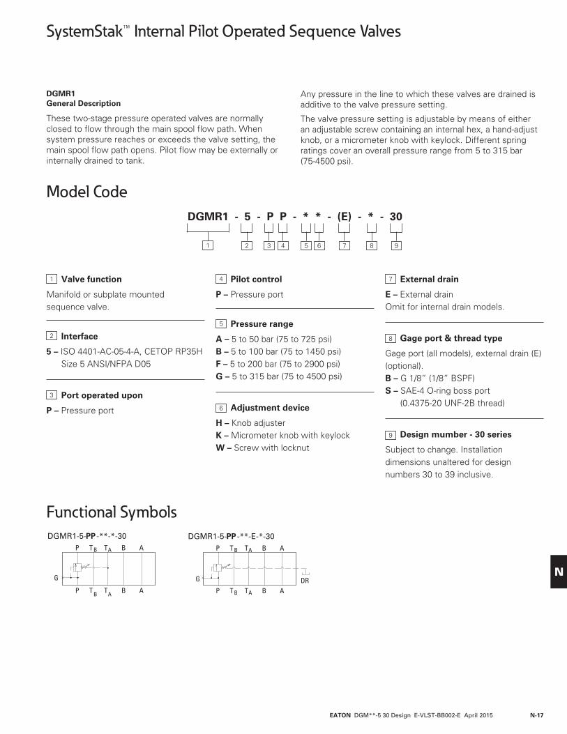
DGMR1 General Description
These two-stage pressure operated valves are normally closed to flow through the main spool flow path. When system pressure reaches or exceeds the valve setting, the main spool flow path opens. Pilot flow may be externally or internally drained to tank.
Any pressure in the line to which these valves are drained is additive to the valve pressure setting.
The valve pressure setting is adjustable by means of either an adjustable screw containing an internal hex, a hand-adjust knob, or a micrometer knob with keylock. Different spring ratings cover an overall pressure range from 5 to 315 bar (75-4500 psi).
P
P
T B
T B
TA
TA
B
B
A
A
DGMR1-5-PP -**-*-30P
P
T B
T B
TA
TA
B
B
A
A
DGMR1-5-PP -**-E-*-30
G G DR
Valve function
Manifold or subplate mounted sequence valve.
Interface
5 – ISO 4401-AC-05-4-A, CETOP RP35H Size 5 ANSI/NFPA D05
Port operated upon
P – Pressure port
Pilot control
P – Pressure port
Pressure range
A – 5 to 50 bar (75 to 725 psi)B – 5 to 100 bar (75 to 1450 psi)F – 5 to 200 bar (75 to 2900 psi)G – 5 to 315 bar (75 to 4500 psi)
Adjustment device
H – Knob adjusterK – Micrometer knob with keylockW – Screw with locknut
External drain
E – External drainOmit for internal drain models.
Gage port & thread type
Gage port (all models), external drain (E) (optional).B – G 1/8” (1/8” BSPF)S – SAE-4 O-ring boss port
(0.4375-20 UNF-2B thread)
Design mumber - 30 series
Subject to change. Installation dimensions unaltered for design numbers 30 to 39 inclusive.
DGMR1 - 5 - P P - * * - (E) - * - 30
1 7 93 4 5 6 82
1
2
3
4
6
5
7
8
9
EATON DGM**-5 30 Design E-VLST-BB002-E April 2015N-18
N
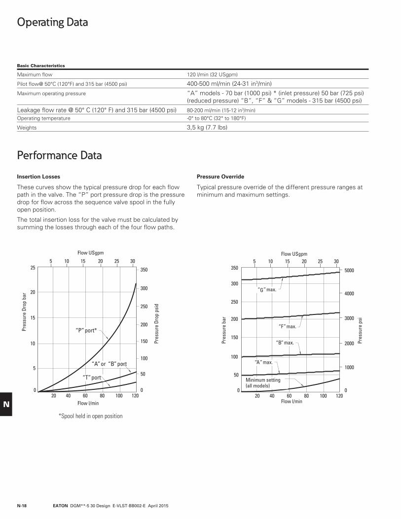
Operating Data
Performance Data
Insertion Losses
These curves show the typical pressure drop for each flow path in the valve. The “P” port pressure drop is the pressure drop for flow across the sequence valve spool in the fully open position.
The total insertion loss for the valve must be calculated by summing the losses through each of the four flow paths.
Pressure Override
Typical pressure override of the different pressure ranges at minimum and maximum settings.
Pres
sure
Dro
p ba
r
Pres
sure
Dro
p ps
id
15
10
100
00
Flow l/min
Flow USgpm
20 40 60 80 100 120
5 10 15 20 25 30
550
25
20
Pres
sure
bar
Pres
sure
psi200
150
100
4000
3000
2000
00
Flow l/min
Flow USgpm
20 40 60 80 100 120
5 10 15 20 25 30
501000
300
350
250
5000
150
200
250
300
350
“A” or “B” port
“P” port*
“T” port
“G” max.
“F” max.
“B” max.
“A” max.
Minimum setting(all models)
*Spool held in open position
Basic Characteristics
Maximum flow 120 l/min (32 USgpm)
Pilot flow@ 50°C (120°F) and 315 bar (4500 psi) 400-500 ml/min (24-31 in3/min)
Maximum operating pressure “A” models - 70 bar (1000 psi) * (inlet pressure) 50 bar (725 psi) (reduced pressure) “B”, “F” & “G” models - 315 bar (4500 psi)
Leakage flow rate @ 50° C (120° F) and 315 bar (4500 psi) 80-200 ml/min (15-12 in3/min)Operating temperature -0° to 80°C (32° to 180°F)
Weights 3,5 kg (7.7 lbs)

EATON DGM**-5 30 Design E-VLST-BB002-E April 2015 N-19
N
Installation Dimensions
DGMR1-5-PP-**-30 Sequence Valve mm (inches)
See page 37 for optional adjustment devices. See page 38 for interface dimensions.
*External drain and gage port threads
“S” models - SAE-4 O-ring boss port (0.4375-20 UNF-2B thread).
“B” models - G 1/8 (1/8 BSPF)
Note: Back pressure in drain is added to this setting for internal drain models only.
* Gage port. Externalconnection port thread
60(2.36)
10(0.39)
30,5(1.20)
48(1.89)
“W” models (max. ext.)
Wrench size
11,5(0.45)
ISO 4401-AC-05-4-A (NFPA D05)Mounting surface
13,5(0.53)
4 mounting holes 6,9 (0.27) through 9,50 (0.37) counterbore
46,5 (1.83) deep for bolt extenders (order separately)BKE-6M-60M (M6 metric) orBKE-4-60M (.2500-20 UNC). Torque: 11,3-14,7 Nm (100-130 lb. in.)
130(5.12)
37(1.46)
11,7(0.46)
28,4(1.12)
69,5(2.74)
71,6(2.82)max.
20,4(0.80)
Adjust clockwise to increase pressure setting.
*External drain port. Plugged for internal drain
* Gage port. Externalconnection port thread
T B
B
P
A
TA
128(5.04)
3rd angleprojection
13 (1/2”)
Hex key 4 (5/32”)
EATON DGM**-5 30 Design E-VLST-BB002-E April 2015N-20
N
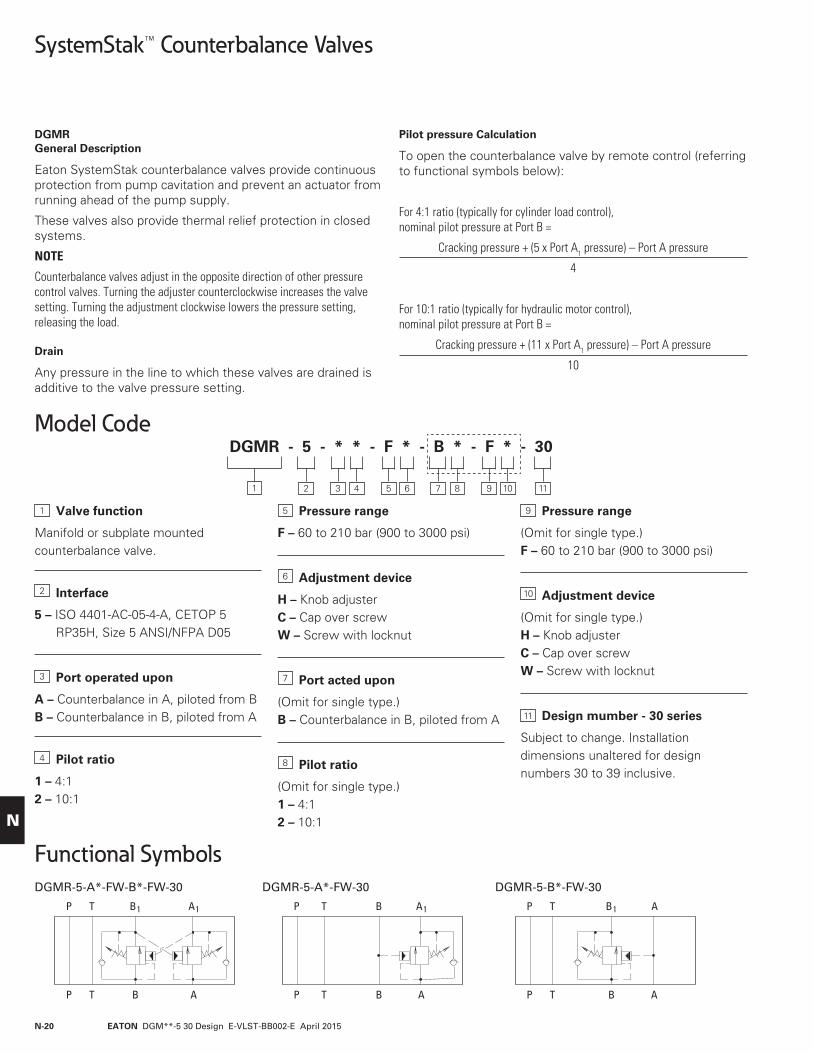
Valve function
Manifold or subplate mounted counterbalance valve.
Interface
5 – ISO 4401-AC-05-4-A, CETOP 5 RP35H, Size 5 ANSI/NFPA D05
Port operated upon
A – Counterbalance in A, piloted from BB – Counterbalance in B, piloted from A
Pilot ratio
1 – 4:12 – 10:1
Pressure range
F – 60 to 210 bar (900 to 3000 psi)
Adjustment device
H – Knob adjusterC – Cap over screwW – Screw with locknut
Port acted upon
(Omit for single type.)B – Counterbalance in B, piloted from A
Pilot ratio
(Omit for single type.)1 – 4:12 – 10:1
Pressure range
(Omit for single type.)F – 60 to 210 bar (900 to 3000 psi)
Adjustment device
(Omit for single type.)H – Knob adjusterC – Cap over screwW – Screw with locknut
Design mumber - 30 series
Subject to change. Installationdimensions unaltered for designnumbers 30 to 39 inclusive.
SystemStak™ Counterbalance Valves
Functional Symbols
Model Code
DGMR General Description
Eaton SystemStak counterbalance valves provide continuous protection from pump cavitation and prevent an actuator from running ahead of the pump supply.
These valves also provide thermal relief protection in closed systems.
NOTE
Counterbalance valves adjust in the opposite direction of other pressure control valves. Turning the adjuster counterclockwise increases the valve setting. Turning the adjustment clockwise lowers the pressure setting, releasing the load.
Drain
Any pressure in the line to which these valves are drained is additive to the valve pressure setting.
Pilot pressure Calculation
To open the counterbalance valve by remote control (referring to functional symbols below):
For 4:1 ratio (typically for cylinder load control), nominal pilot pressure at Port B =
Cracking pressure + (5 x Port A1 pressure) – Port A pressure
4
For 10:1 ratio (typically for hydraulic motor control), nominal pilot pressure at Port B =
Cracking pressure + (11 x Port A1 pressure) – Port A pressure
10
A1
A
P
P
T
T
B1
DGMR-5-A*-FW-B*-FW-30
B
A1
A
P
P
T
T
B
DGMR-5-A*-FW-30
B
A
A
P
P
T
T
B1
DGMR-5-B*-FW-30
B
DGMR - 5 - * * - F * - B * - F * - 30
1 7 113 4 5 6 9 1082
1
2
3
4
5
6
7
8
9
10
11

EATON DGM**-5 30 Design E-VLST-BB002-E April 2015 N-21
N
Operating Data
Performance DataDGMR Performance Curves Insertion Losses
These curves show the typical pressure drop for each flow path in the valve for fluid viscosity range 21-32 cSt (100-150 SSU).
The total insertion loss for the valve is calculated by summing the losses through each of the four flow paths.
1. “P” port for all models. “A” port of DGMR-5-B*-30 “B” port of DGMR-5-A*-30
2. “T” port for all models.
3. Free flow through service port of counterbalance.
4. Piloted port open through service port of counterbalance.
Pres
sure
Dro
p ba
r
Pres
sure
Dro
p ps
id
30
20 300
00
Flow l/min
Flow USgpm
20 40 60 80 100 120
5 10 15 20 25 30
10 150
60
40
450
600
75050
4
3
Pres
sure
Dro
p ps
id
4
0
Flow l/min
Flow USgpm
40 80
10 20
2
201
30
120
2
40
20 60 1000
3
1
10
30
50
Pres
sure
Dro
p ba
r
5 1 5 2 5
Basic Characteristics
Maximum flow 120 l/min (32 USgpm)
Load holding leakage @70% of pressure setting 0.35 ml/min.
Cracking Pressure Adjustment Range 60-210 bar (900-3000 psi)
Pilot Ratios 4:1, 10:1
Maximum operating pressure 315 bar (4500 psi)
Leakage flow rate @ 50° C (120° F) and 315 bar (4500 psi) 5 drops/min, Port A to Port A1 at 70% of crack setting
Operating temperature -40° to 80°C (-40° to 180°F)
Weights 4,5 kg (10 lbs)

EATON DGM**-5 30 Design E-VLST-BB002-E April 2015N-22
N
Installation Dimensions
DGMR-5-A*-FW-B*-FW-30 Dual Counterbalance on A & B Ports mm (inches)
See page 37 for optional adjustment devices. See page 38 for interface dimensions.
60(2.36)
65,6(2.58)
“W” models (max. ext.)both ends
Wrench sizeISO 4401-AC-05-4-A (NFPA D05)Mounting surface
4 mounting holes 6,90 (0.27) through 9,50 (0.37) counterbore
46,5 (1.83) deep for bolt extenders (order separately) BKE-6M-60M (M6 metric) or BKE-4-60M (.2500-20 UNC). Torque: 11,3-14,7 Nm (100-130 lb. in.)
155,5(6.12)
50(1.97)
11,7(0.46)
33,2(1.31)
69,5(2.74)
71,6(2.82)
21,5(0.85)
13,5(0.53)
3rd angleprojection
Hex key4 (5/32”)
13 (1/2”)
Adjust counterclockwise to increasepressure setting.

EATON DGM**-5 30 Design E-VLST-BB002-E April 2015 N-23
N
Installation Dimensions
DGMR-5-A*-FW-30 Counterbalance Port A, Piloted from B mm (inches)
DGMR-5-B*-FW-30 Counterbalance Port B, Piloted from A
See page 37 for optional adjustment devices. See page 38 for interface dimensions.
65,6(2.58)
“W” models (max. ext.)
ISO 4401-AC-05-4-A (NFPA D05)Mounting surface
4 mounting holes(see page 22)
142,6 (5.61)50
(1.97)
11,7(0.46)
33,2(1.31)
69,5(2.74)
71,6(2.82)
Hex key
21,5(0.85)
60(2.36)
65,6(2.58)
“W” models (max. ext.)
Wrench size
ISO 4401-AC-05-4-A (NFPA D05)Mounting surface
142,6 (5.61) 11,7(0.46)
33,2(1.31)
69,5(2.74)
71,6(2.82)
Hex key
21,5(0.85)
60(2.36)
4 mounting holes (see page 23)
Wrench size13 (1/2”)
4 (5/32”)
4 (5/32 ”)
13 (1/2”)
Adjust counterclockwise toincrease pressure setting.
Adjust counterclockwise toincrease pressure setting.
37 (1.46)

EATON DGM**-5 30 Design E-VLST-BB002-E April 2015N-24
N
SystemStak™ Flow Control Valves
DGMFN General Description
These valves are adjustable, non-compensated flow restrictors. An integral check valve around the regulating orifice allows free flow in one direction and metered flow in the other.
Control is available in “A” only, “B” only, and “A” and “B” ports as an “X” type (meter–in) or “Y” type (meter-out).
The “P” port is available only in the “X” type (meter-in) and does not contain a reverse flow check.
The valve flow setting is adjustable by means of either a hex key adjusting screw and locknut, a hand-adjust knob, or a micrometer knob with keylock.
A normal or fine metering capability is available. See the pressure drop curves on page 26 for detailed performance difference.
Valve function
Manifold or subplate mounted flow control valve.
Interface
5 – ISO 4401-AC-05-4-A, CETOP 5 Size 5 RP35H ANSI/NFPA D05
Direction of flow
X – Meter-inY – Meter-out
Port operated upon
A – Cylinder port “A” (single or dual type)
B – Cylinder port “B” (single type only)P – Pressure port (single type only)
Adjustment range
1 – Fine control2 – Normal control
Adjustment device
H – Knob adjusterK – Micrometer knob with keylockW – Screw with locknut
Port operated upon: second function
(Omit for single flow control models.)B – B cylinder port (Dual type)
Adjustment range: second function
(Omit for single flow control models.)1 – Fine control2 – Normal control
Adjustment device: second function
(Omit for single flow control models.)H – Knob adjusterK – Micrometer knob with keylockW – Screw with locknut
Design number - 30 series
Subject to change. Installation dimensions unaltered for design numbers 30 to 39 inclusive.
Model CodeDGMFN - 5 - * - * * * - B * * - 30
1 7 103 4 5 6 982
1
2
3
4
5
6
7
8
9
10
A
P
P
TDGMFN-5-X-P**-30
B
B A B A
T
A
P
P
TDGMFN-5-Y-A**-B**-30
B
AB
T
A
P
P
TDGMFN-5-X-B**-30
B
AB
TA
P
P
T
DGMFN-5-X-A**-B**-30
BT A
P
P
TDGMFN-5-X-A**-30
B
AB
T
A
P
P
TDGMFN-5-Y-A**-30
B
AB
T A
P
P
TDGMFN-5-Y-B**-30
B
AB
T

EATON DGM**-5 30 Design E-VLST-BB002-E April 2015 N-25
N
Operating Data
Performance DataMinimum Controlled Flow/No-Flow Leakage
Internal leakage will vary from valve to valve and with the pressure differential across the check. Approximate levels are:
Pressure Drop
The curves below show the pressure drop through individual flow passages. Curves labeled “metered flow/pressure drop” refer to the pressure drop through only the passage containing the flow control regulating orifice. Total valve insertion loss is a value derived from graph 1 or 2 plus the appropriate values of lines 1, 2 and 3 from graph 3.
Pressure Drop Leakage* bar (psi) cc/min (in3/min)
50 (725) 160 (9.5) 100 (1450) 320 (19) 200 (2900) 640 (38) 315 (4500) 990 (60) * Equals minimum controllable flow rate at the pressures stated.
Graph 1
Metered flow pressure drop. Normal adjustment – “2” models (see model code, page 24).
Graph 2
Metered flow pressure drop. Fine adjustment – “1” models (see model code, page 24).
Graph 3
Free flow pressure drop across check valve.
Note: “Turn” or “Turns” on curves in graphs 1 and 2, above, refer to turn of adjustment device from fully closed position.
Graph 3
1 – “P” port of all models except DGMFN-5-X-P**-30 “B” and “T” ports of DGMFN-5-X-P**-30
2 – “T” port of all models except DGMFN-5-X-P**-30 “A” ports of DGMFN-5-X-P**-30
3 – Pressure drop across reverse free flow check valve
Pres
sure
Dro
p ba
r
Pres
sure
Dro
p ps
i
150
100
1000
00
Flow l/min
Flow USgpm
20 40 60 80 100 120
5 10 15 20 25 30
50
300
250
2000
4000
5000350
200 3000
10 turns8 turns6 turns
1 tu
rn
1 1/
2 tu
rns
2 tu
rns
4 turns
150
100
1000
00
Flow l/min
Flow USgpm
20 40 60 80 100 120
5 10 15 20 25 30
50
300
250
2000
4000
5000350
200 3000
1/2
turn
2 tu
rns
3 tu
rns
4 tu
rns
8 turns
7 turns
1 turn
6
4
40
00
Flow l/min
Flow USgpm
40 80 120
10 20
220
12
8
60
80
100
120
160
10 140
30
1
2
3
9 turns
1/2
turn
Pres
sure
Dro
p ba
r
Pres
sure
Dro
p ps
i
Pres
sure
Dro
p ba
r
Pres
sure
Dro
p ps
i
Basic Characteristics
Maximum flow 120 l/min (32 USgpm)
Maximum operating pressure 315 bar (4500 psi)
Operating temperature 20° to 50°C (70° to 120°F)
Weights 3,1 kg (7 lbs)

EATON DGM**-5 30 Design E-VLST-BB002-E April 2015N-26
N
Installation Dimensions
DGMFN-5-X-P & DGMFN-5-Y-A Single Flow Controls mm (inches)
DGMFN-5-X-A Single Flow Control mm (inches)
See page 37 for optional adjustment devices. See page 38 for interface dimensions.
4 mounting holes 6,9 (0.27) through 9,50 (0.37) counterbore 36,5 (1.44) deep
for bolt extenders (order separately)BKE-6M-50M (M6 metric) orBKE-4-50M (.2500-20 UNC). Torque: 11,3-14,7 Nm (100-130 lb. in.)
ISO 4401-AC-05-4-A(NFPA D05)Mounting surface
50(1.97)
A“W” models (max. ext.)
13,5(0.53)
128 (5.04)37
(1.46)
11,7(0.46)
B
71,6(2.82)max.
B
P
A
T B
Wrench size
69,5(2.74)
Hex key
Rotate clockwiseto decrease flow
30(1.18)
139 (5.47)
No hex plug onDGMFN-5-X-Pmodels
3rd angleprojection
13 (1/2”)
4 (5/32”)
50(1.97)
52,7(2.07)
“W” models (max. ext.)
ISO 4401-AC-05-4-A(NFPA D05)Mounting surface
13,5(0.53)
128 (5.04)37
(1.46)
11,7(0.46)
33,2(1.31)
71,6(2.82)max.
B
P
A
Wrench size
69,5(2.74)
Hex key
Rotate clockwiseto decrease flow
20(0.79)
4 mounting holes(See above forspecifications)
139 (5.47)13 (1/2”)
4 (5/32”)
TA
T B TA
Model A B
DGMFN-5-X-P 60,4 (2.38) 28,4 (1.12)DGMFN-5-Y-A 52,7 (2.07) 33,2 (1.31)

EATON DGM**-5 30 Design E-VLST-BB002-E April 2015 N-27
N
DGMFN-5-X-B Single Flow Control mm (inches)
DGMFN-5-Y-B Single Flow Control
See page 37 for optional adjustment devices. See page 38 for interface dimensions.
Hex keyRotate clockwise to decrease flow
50(1.97)
52,7(2.07)
“W” models (max. ext.)
ISO 4401-AC-05-4-A (NFPA D05)Mounting surface
13,5(0.53)
128 (5.04)37
(1.46)
11,7(0.46)
33,2(1.31)
71,6(2.82)max.
B
P
A
Wrench size
69,5(2.74)
20(0.79)
139 (5.47)
50(1.97)
52,7(2.07)
“W” models (max. ext.)
13,5(0.53)
128 (5.04) 37(1.46)
11,7(0.46)
33,2(1.31)
71,6(2.82)max.
B
P
A
Wrench size
69,5(2.74)
Hex key
30(1.18)
139 (5.47)
Rotate clockwise to decrease flow
4 mounting holes(See page 27 forspecifications)
4 mounting holes(See page 27 forspecifications)
13 (1/2”)
4 (5/32”)
4 (5/32”)
13 (1/2”)
ISO 4401-AC-05-4-A (NFPA D05)Mounting surface
T B TA
T B TA
Installation Dimensions

EATON DGM**-5 30 Design E-VLST-BB002-E April 2015N-28
N
DGMFN-5-Y Dual Flow Control mm (inches)
DGMFN-5-X Dual Flow Control mm (inches)
See page 37 for optional adjustment devices. See page 38 for interface dimensions.
Hex key
50(1.97)
52,7(2.07)
“W” models (max. ext.) typ. both ends
13,5(0.53)
128 (5.04) 37(1.46)
11,7(0.46)
33,2(1.31)
71,6(2.82)max.
B
P
A
Wrench sizeboth ends
69,5(2.74)
Hex key
30(1.18)
ISO 4401-AC-05-4-A (NFPA D05)Mounting surface
Rotate clockwise to decrease flow inport “B”
Rotate clockwise to decrease flow inport “A”
50(1.97)
52,7(2.07)
“W” models (max. ext.)typ. both ends
128 (5.04)37
(1.46)
11,7(0.46)
33,2(1.31)
71,6(2.82)max.
B
P
A
Wrench sizeboth ends
69,5(2.74)
20(0.79)
ISO 4401-AC-05-4-A (NFPA D05)Mounting surface
Rotate clockwise to decrease flow inport “B”
Rotate clockwise to decrease flow inport “A”
4 mounting holes (See page 27for specifications)
4 mounting holes (See page 27for specifications)
13 (1/2 ”)
4 (5/32”)
13,5(0.53)
13 (1/2”)
4 (5/32”)
T B TA
T B TA
Installation Dimensions
EATON DGM**-5 30 Design E-VLST-BB002-E April 2015 N-29
N
SystemStak™ Pilot Operated Check Valves
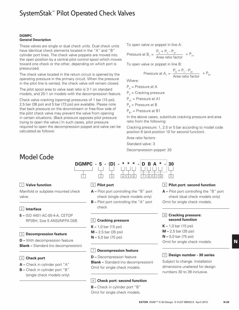
DGMPC General Description
These valves are single or dual check units. Dual check units have identical check elements located in the “A” and “B” cylinder port lines. The check valve poppets are moved into the open position by a central pilot control spool which moves toward one check or the other, depending on which port is pressurized.
The check valve located in the return circuit is opened by the operating pressure in the primary circuit. When the pressure in the pilot line is vented, the check valve will remain closed.
The pilot spool area to valve seat ratio is 3:1 on standard models, and 20:1 on models with the decompression feature.
Check valve cracking (opening) pressures of 1 bar (15 psi), 2,5 bar (36 psi) and 5 bar (73 psi) are available. Please note that back pressure on the downstream or free-flow side of the pilot check valve may prevent the valve from opening in certain situations. (Back pressure opposes pilot pressure trying to open the valve.) In such cases, pilot pressure required to open the decompression poppet and valve can be calculated as follows:
To open valve or poppet in line A:
To open valve or poppet in line B:
Where:
PA = Pressure at A
PC = Cracking pressure
PA1 = Pressure at A1
PB = Pressure at B
PB1 = Pressure at B1
In the above cases, substitute cracking pressure and area ratio from the following:
Cracking pressure: 1, 2.5 or 5 bar according to model code position 6 (and position 10 for second function).
Area ratio factors:
Standard valve: 3
Decompression poppet: 20
PA + PC - PA1
Area ratio factorPressure at B1 = + PA1
PB + PC - PB1
Area ratio factorPressure at A1 = + PB1
Model Code
Valve function
Manifold or subplate mounted check valve.
Interface
5 – ISO 4401-AC-05-4-A, CETOP RP35H, Size 5 ANSI/NFPA D05
Decompression feature
D – With decompression featureBlank – Standard (no decompression)
Check port
A – Check in cylinder port “A”B – Check in cylinder port “B”
(single check models only)
Pilot port
A – Pilot port controlling the “B” port check (single check models only)
B – Pilot port controlling the “A” port check
Cracking pressure
K – 1,0 bar (15 psi)M – 2,5 bar (35 psi)N – 5,0 bar (75 psi)
Decompression feature
D – Decompression featureBlank – Standard (no decompression)Omit for single check models.
Check port: second function
B – Check in cylinder port “B”Omit for single check models.
Pilot port: second function
A – Pilot port controlling the “B” port check (dual check models only)
Omit for single check models.
Cracking pressure: second function
K – 1,0 bar (15 psi)M – 2,5 bar (35 psi)N – 5,0 bar (75 psi)Omit for single check models.
Design number - 30 series
Subject to change. Installation dimensions unaltered for design numbers 30 to 39 inclusive.
DGMPC - 5 - (D) - * * * - D B A * - 30
1 114 5 6 9 10872 3
1
2
3
4
5
6
7
8
9
10
11

EATON DGM**-5 30 Design E-VLST-BB002-E April 2015N-30
N
Functional Symbols
A
P
P
TDGMPC-5-BA*-30
B
A1B1
TA
P
P
TDGMPC-5-AB*-30
B
A1B1
T A
P
P
TDGMPC-5-AB*-BA*-30
B
A1B1
T
Basic Characteristics
Maximum flow 120 l/min (32 USgpm)
Maximum operating pressure 315 bar (4500 psi)
Leakage @ 50°C (120°F) Poppet @ 35 bar (500 psi)
Standard models 0.3 ml/min.
“D” models 1.0 ml/min.
Piston @315 bar (4500 psi) 20°C to 50 °C (70 to 120° F)
Operating temperature 20°C to 50°C (70° to 120°F)
Weights 2,9 kg (6.4 lbs)
Operating Data
Performance DataDGMPC Pressure Drop
The curves below show pressure drop through each functional flow path in the valve. The total insertion loss for the valve must be calculated by summing the losses through the four applicable flow paths.
Model Type Curve Number
P T A B
DGMPC-5-(D)-AB*-30 1 2 - 5 • 3 - - 4DGMPC-5-(D)-BA*-30 1 2 • 3 - - - 5 4DGMPC-5-(D)-AB*-(D)-BA*-30 1 2 - 5 - 5
• Flow toward actuator without check – single check only
Flow from actuator without check – single check only
Use K, M, or N cracking pressure curve as applicable
M
K
N
Pres
sure
dro
p ba
r
Pres
sure
dro
p ps
i
6
4
00
Flow l/min
Flow USgpm
20 40 60 80 100 120
5 10 15 20 25 30
2
8
10
16
14
12
18
20
22
24
50
100
150
200
250
300
1
2
3
4
5

EATON DGM**-5 30 Design E-VLST-BB002-E April 2015 N-31
N
Installation Dimensions
DGMPC-5-30 Pilot Operated Check Valve mm (inches)
See page 38 for interface dimensions.
30(1.18)
50(1.97)
9,9(0.39)
ISO 4401-AC-05-4-A (NFPA D05)Mounting surface
13,5(0.53)
128 (5.04)
37(1.46)
11,7(0.46)
33,2(1.31)
71,6(2.82)max.
B
P
A
T B69,5
(2.74)
4 mounting holes 6,9 (0.27) through 9,50 (0.37) counterbore
36,5 (1.44) deep for bolt extenders (order separately) BKE-6M-50M (M6 metric) or BKE-4-50M (.2500-20 UNC) Torque: 11,3-14,7 Nm (100-130 lb. in.)
9,9(0.39)
TA

EATON DGM**-5 30 Design E-VLST-BB002-E April 2015N-32
N
SystemStak™ Direct Check Valves
DGMDC General Description
These SystemStak valves are self-operating, spring loaded, poppet type single or dual check units.
Location of the check element can be in the “A”, “B”, “P” or “T” port.
A check in the “P” port is available as a “Y” single check model only.
A check in the “T” port is available as an “X” single check model only.
The dual check unit has identical check elements in both the “A” and “B” ports.
Check valve cracking (opening) pressures of 1 bar (15 psi), 2,5 bar (35 psi) and 5 bar (75 psi) are available.
Model Code
Valve function
Manifold or subplate mounted check valve.
Interface
5 – ISO 4401-AC-05-4-A, CETOP RP35H, Size 5 ANSI/NFPA D05
Direction of flow
X – Free flow from actuator (load)Y – Free flow to actuator (load)
Check location
A – Check in cylinder port “A” (“Y” models only)
B – Check in cylinder port “B” (“Y” models only)
P – Check in pressure port “P” (“Y” models only)
T – Check in tank port “TA” (“X” models only)
Cracking pressure
K – 1,0 bar (15 psi)M – 2,5 bar (35 psi)N – 5,0 bar (75 psi)
Check location: second function
Omit for single check models.B – Check in cylinder port “B”
(dual check models only)
Cracking pressure: second function
Omit for single check models.K – 1,0 bar (15 psi)M – 2,5 bar (35 psi)N – 5,0 bar (75 psi)
Design number - 30 series
Subject to change. Installation dimensions unaltered for design numbers 30 to 39 inclusive.
DGMDC - 5 - * - * * - (B) (*) - 30
1 6 7 84 52 3
1
2
3
4
5
6
7
8
A
P
P
T B
DGMDC-5-Y-P*-30TA
B
A B
TAT B A
P
P
T B
DGMDC-5-X-T*-30TA
B
A B
TAT B
A
P
P
T B
DGMDC-5-Y-A*-30TA
B
A B
TAT B
A
P
P
T B
DGMDC-5-Y-B*-30TA
B
A B
TAT B
A
P
P
T B
DGMDC-5-Y-A*-B*-30TA
B
A B
TAT B
EATON DGM**-5 30 Design E-VLST-BB002-E April 2015 N-33
N
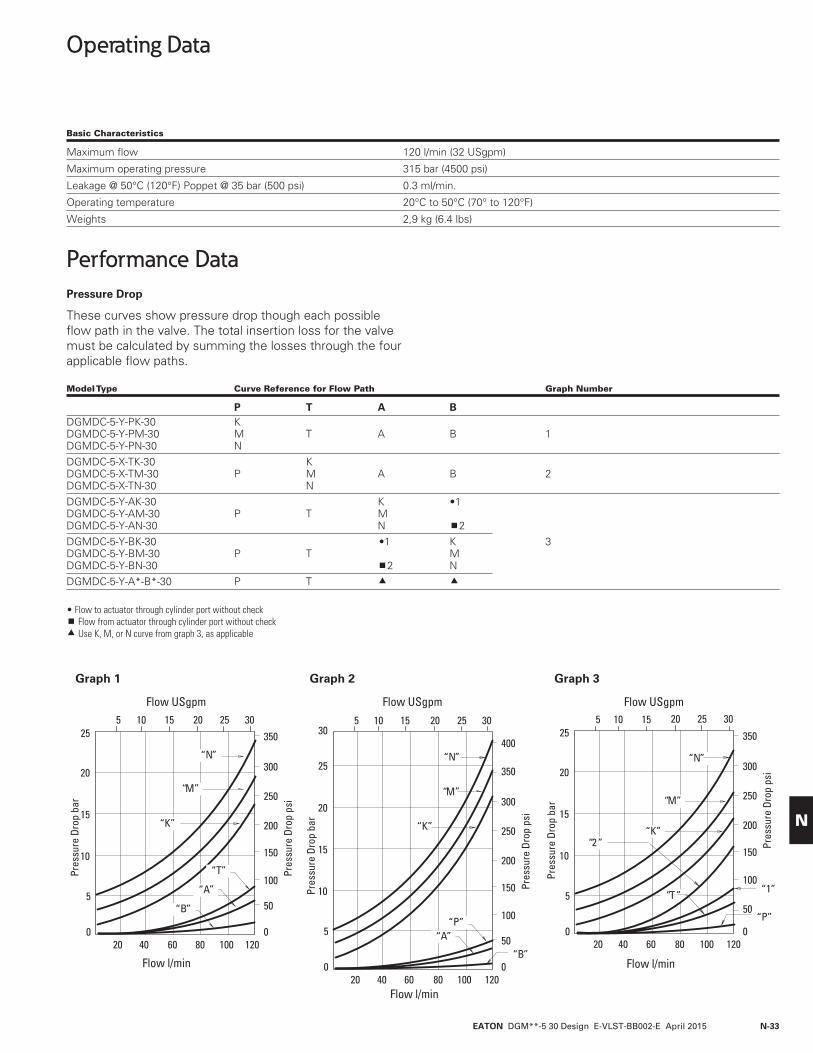
Operating Data
Performance DataPressure Drop
These curves show pressure drop though each possible flow path in the valve. The total insertion loss for the valve must be calculated by summing the losses through the four applicable flow paths.
Model Type Curve Reference for Flow Path Graph Number
P T A BDGMDC-5-Y-PK-30 K DGMDC-5-Y-PM-30 M T A B 1 DGMDC-5-Y-PN-30 N DGMDC-5-X-TK-30 K DGMDC-5-X-TM-30 P M A B 2 DGMDC-5-X-TN-30 N DGMDC-5-Y-AK-30 K •1 DGMDC-5-Y-AM-30 P T M DGMDC-5-Y-AN-30 N 2DGMDC-5-Y-BK-30 •1 K 3 DGMDC-5-Y-BM-30 P T M DGMDC-5-Y-BN-30 2 N DGMDC-5-Y-A*-B*-30 P T
• Flow to actuator through cylinder port without check Flow from actuator through cylinder port without check Use K, M, or N curve from graph 3, as applicable
“N”
“M”
“K”
Pres
sure
Dro
p ba
r
Pres
sure
Dro
p ps
i
15
10
100
00
Flow l/min
Flow USgpm
20 40 60 80 100 120
5 10 15 20 25 30
550
25
20
150
200
250
300
350
“T”
“A”
“B”
“N”
“M”
“K”
Graph 1
Pres
sure
Dro
p ba
r
15
10
100
00
Flow l/min
Flow USgpm
20 40 60 80 100 120
5 10 15 20 25 30
550
25
20
150
200
250
300
350
“P”“A”
“B”
40030
Graph 2
15
10
100
00
Flow l/min
Flow USgpm
20 40 60 80 100 120
5 10 15 20 25 30
550
25
20
150
200
250
300
350
“N”
“M”
“K”
Graph 3
“2 ”
“P”
“T” “1”Pres
sure
Dro
p ps
i
Pres
sure
Dro
p ba
r
Pres
sure
Dro
p ps
i
Basic Characteristics
Maximum flow 120 l/min (32 USgpm)
Maximum operating pressure 315 bar (4500 psi)
Leakage @ 50°C (120°F) Poppet @ 35 bar (500 psi) 0.3 ml/min.
Operating temperature 20°C to 50°C (70° to 120°F)
Weights 2,9 kg (6.4 lbs)

EATON DGM**-5 30 Design E-VLST-BB002-E April 2015N-34
N
50(1.97)
9,9 (0.39) ISO 4401-AC-05-4-A (NFPA D05)Mounting surface
13,5(0.53)
128 (5.04)37
(1.46)
11,7(0.46)
33,2(1.31)
71,6(2.82)max.
B
P
A
T B
69,5(2.76)
30(1.18)
4 mounting holes 0 6,9 (0.27) through 0 9,50 (0.37) counterbore 36,5 (1.44) deep for bolt extenders (order separately)BKE-6M-50M (M6 metric) orBKE-4-50M (.2500-20 UNC). Torque: 11,3-14,7 Nm (100-130 lb. in.) 9,9 (0.39)
(max.)
50(1.97)
ISO 4401-AC-05-4-A (NFPA D05)Mounting surface
13,5(0.53)
30(1.18)
9,9 (0.39)(max.)
50(1.97)
ISO 4401-AC-05-4-A(NFPA D05)Mounting surface
13,5(0.53)
17(.669)
9,9 (0.39)(max.)
4 mounting holes(See above forspecifications)
4 mounting holes(See above forspecifications)
TA
Installation Dimensions
DGMDC-5-Y-A*-B*-30 Dual Direct Check Valve mm (inches)
DGMDC-5-Y-P*-30 Single Direct Check Valve
DGMDC-5-X-T*-30 Single Direct Check Valve
See page 38 for interface dimensions.

EATON DGM**-5 30 Design E-VLST-BB002-E April 2015 N-35
N
56,8 (2.24) “H” models (max. ext.)
2 (5/64”)Hex key required for adjustment
82,9 (3.26)“K” models 45(1.77)
For keyremoval
max. ext.
54,1 (2.13) “H” models (max. ext.)
Hex key required for adjustment
80,1 (3.15)“K” models 45(1.77)
For keyremoval
max. ext.
C “H” models (max. ext.)
Hex keyrequired foradjustment
D“K” models 45(1.77)
For keyremoval
max. ext.
74,4 (2.93)
Hex key required for adjustment
H – Handknob C – Cap over screwW – Screw with locknut
65,6 (2.58) 68,5 (2.70)
13 (1/2”)Wrench size
Hex key4 (5/32)
2 (5/64”)
2 (5/64”)
2 (5/64”)
13 (1/2”)Wrench size
Knob Adjusters
DGMC DGMC2 (dual type) DGMR1 DGMX2
DGMC2 (crossport type)
DGMFN
DGMR
Adjustment of valve setting is only possible while key is inserted and turned to engage driving pin. When key is removed, adjuster knob can be freely spun and does not engage with setting mechanism.
Adjustment of valve setting is only possible while key is inserted and turned to engage driving pin. When key is removed, adjuster knob can be freely spun and does not engage with setting mechanism.
Adjustment of valve setting is only possible while key is inserted and turned to engage driving pin. When key is removed, adjuster knob can be freely spun and does not engage with setting mechanism.
Model C D
DGMFN-5-X-P 68,9 (2.37) 95 (3.74)DGMFN-5-Y-A 61,9 (2.44) 88 (3.46)
EATON DGM**-5 30 Design E-VLST-BB002-E April 2015N-36
N
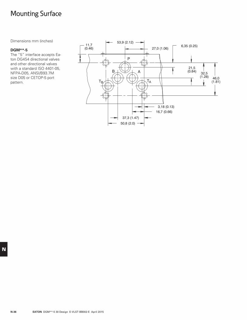
Mounting Surface
Dimensions mm (inches)
DGM**-5 The “5” interface accepts Ea-ton DG4S4 directional valves and other directional valves with a standard ISO 4401-05, NFPA-D05, ANSI/B93.7M size D05 or CETOP-5 port pattern.
EATON DGM**-5 30 Design E-VLST-BB002-E April 2015 N-37
N
Bolt Extender Kits
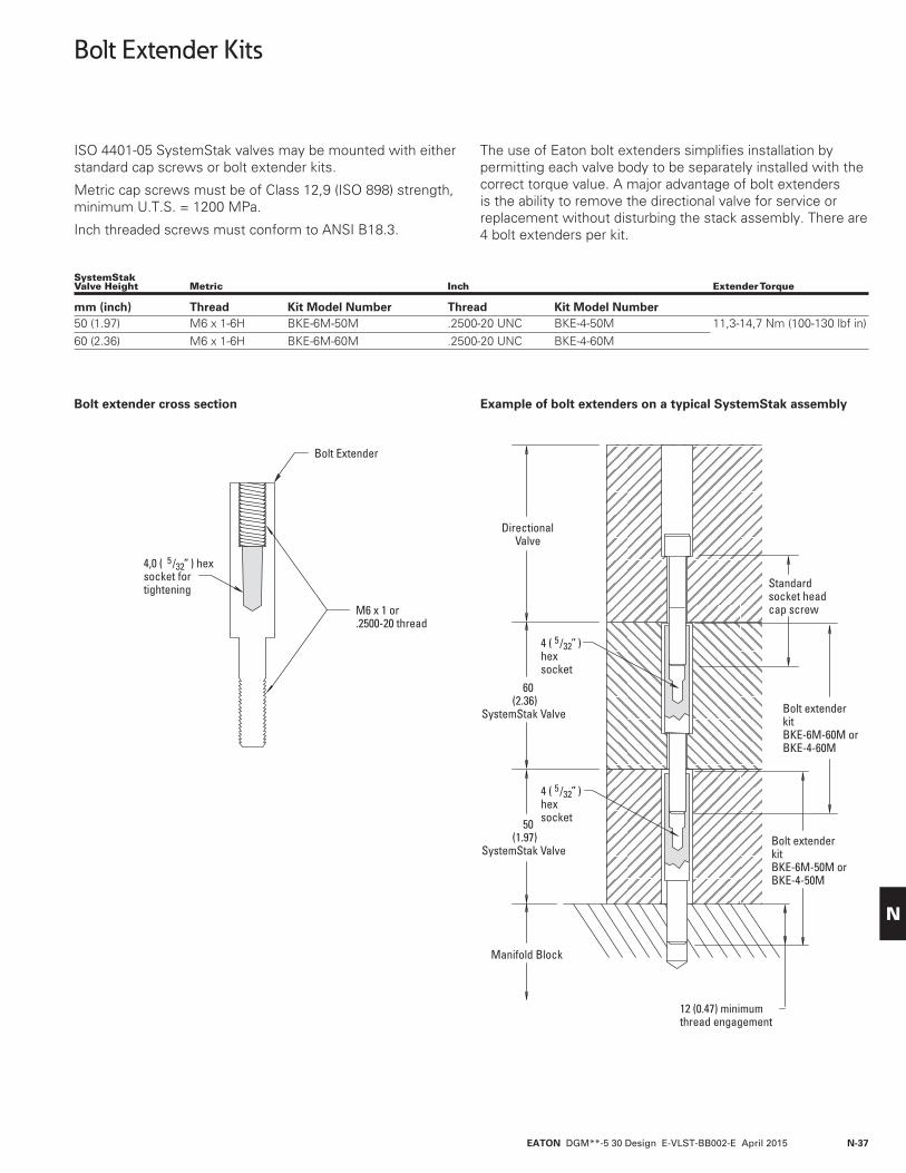
ISO 4401-05 SystemStak valves may be mounted with either standard cap screws or bolt extender kits.
Metric cap screws must be of Class 12,9 (ISO 898) strength, minimum U.T.S. = 1200 MPa.
Inch threaded screws must conform to ANSI B18.3.
The use of Eaton bolt extenders simplifies installation by permitting each valve body to be separately installed with the correct torque value. A major advantage of bolt extenders is the ability to remove the directional valve for service or replacement without disturbing the stack assembly. There are 4 bolt extenders per kit.
Bolt extender cross section Example of bolt extenders on a typical SystemStak assembly
SystemStak Valve Height Metric Inch Extender Torque
mm (inch) Thread Kit Model Number Thread Kit Model Number50 (1.97) M6 x 1-6H BKE-6M-50M .2500-20 UNC BKE-4-50M 11,3-14,7 Nm (100-130 lbf in)60 (2.36) M6 x 1-6H BKE-6M-60M .2500-20 UNC BKE-4-60M
DirectionalValve
60(2.36)
SystemStak Valve
50(1.97)
SystemStak Valve
Manifold Block
M6 x 1 or.2500-20 thread
Bolt Extender
4,0 ( 5 /32” ) hexsocket fortightening Standard
socket headcap screw
Bolt extender kitBKE-6M-60M orBKE-4-60M
Bolt extender kitBKE-6M-50M orBKE-4-50M
12 (0.47) minimum thread engagement
4 ( 5 /32” )hexsocket
4 ( 5 /32” )hexsocket

EATON DGM**-5 30 Design E-VLST-BB002-E April 2015N-38
N
Subplates & Blanking Plate
Valves, subplates and blanking plates must be ordered separately.
DGSM(E) Subplate (rated at 210 bar (3000 psi)
Millimeters (inches)
DGMAB-5-30 Blanking Plate
Model Numbers “E” Thread Tube Size Dimension “A”
DGSM-01-20-T8 .750-16 UNF-2B 1⁄2” O.D. 31,75 (1.25)DGSME-01-20-T8 .750-16 UNF-2B 1⁄2” O.D. 38,10 (1.50)* Ports on side-connection Model DGSME-01-20-T8 only.
“TA” Tank Conn. *
39,6(1.56)
50,8 (2.00)
B T
P
AB
10,4 (.41)
10,4 (.41)
23,9 (.94)
92(3.62)
46(1.8)
23,1 (.91)
47,8(1.88)
23,1 (.91)
68,3(2.69)
18,3* (.72)
23,9 (.94)
A
101,6 (4.00)
114,3(4.50)
43,7(1.72)
20,6 (.81)
5,6 (.22)15,8 (.62)
5,6 (.22)28,5 (1.12)
79,4(3.12)33,02 (1.30)
12,7 (.50) 54(2.12)
37,3*(1.47)
26,16(1.03)
15 (.59)
6,35 (.25)
11,2(.44) R
11,9 (.47) R “P” Pressure Conn.*
10,3 (.41) D. Thru 20,6 (.81) D. Spotface 4 holes for mounting
.438 Dia. System ports4 holes
.2500-20 UNC-2B Thd. 4-holes for mounting
“E” Thd. 4 holes System connections.
“A” Cyl. Conn.*
“B” Cyl. Conn.*
50,8 (2.00)
57,9(2.28)
54,0 (2.125)
9,4 (.37)
19,1 (.75)
69,7 (2.745)67,2 (2.725)
11,5 (.454)
46,0(1.81)
32,5(1.28)
21,4 (.844)6,35 (.250)
.438 dia. – .25 deep5 places
.281 dia. thru.
.422 c ’bore to depth shown4 places

EATON DGM**-5 30 Design E-VLST-BB002-E April 2015 N-39
N
Subplates & Blanking Plates
DGVME Side Ported Subplates (rated at 315 bar (4500 psi) “5” interface
Model “X” Assembly
DGVME-5-SP-10-T06 .5625 525815DGVME-5-SP-10-T08 .7500 525816DGVME-5-SP-10-T10 .8750 525817DGVME-5-SP-10-T12 1.0625 525818DGVME-5-SP-PD-10-T10† .8750 526003DGVME-5-SP-PD-10-T12† 1.0625 526004† Model with pilot and drain ports.
79,4 (3.125)54 (2.125)
3,2 (.125)16,6 (.656)
27,0 (1.062)37,3 (1.469)
101,6 (4.00)
“X” size SAE straight thread
114,3(4.50)
92,0(3.625)
46,0(1.812)
32,5(1.281)
21,4 (.844)6,35 (.250)
43,6(1.72)
.4375 dia. 4 places
Pilot port (5P only).5625 –18 UNF SAE straight threadPlug if internally piloted
“X” size SAE str. thd.
“X” size SAE str. thd.
“X” size SAE str.thd.
A
X
P
B
T
Y
Drain port (5P only).5625 –18 UNF SAE straight threadPlug if internally drained
.421 dia. thru
.656 dia c’bore .468 deep 4 places
3,17 (.125) dia. 2 places (5P only)
TA
A
P
B X
Y
20,6 (.81)
33,3 (1.31)
15,7 (.62)50 (1.97)
20,6 (.81)12,7 (.50)
12,7 (.50)
20,6 (.81)
39,6(1.56)
76,2(3.00)
14,2 (.56) 20,6(.81)
14,2(.56)
39,6 (1.56)
2,4 (.094)
2,4 (.094)
11,1 (.437)
11,2 (.44)
11,1 (.437)
12,7 (.50)
.2500-20 UNC-2B thd.12,7 (.50) deep 4 holes for mounting
11,2 (.44)

EATON DGM**-5 30 Design E-VLST-BB002-E April 2015N-40
N
79,4 (3.125)
54 (2.125)
3,2 (.125)
12,7 (.50)
16,6 (.656)27,0 (1.062)37,3 (1.469)
101,6 (4.00)
.421 dia. thru
.656 dia c’bore .468 deep ’4 places
3,17 (.125) dia. 2 places(5P only)
114,3(4.50)
92,0(3.625)
46,0(1.812)
32,5(1.281)
21,4 (.844)6,35 (.250)
.4375 dia.4 places
P
A
BT
Y
XP
B
TA
A
X
Y
69,8 (2.75)(39,6 (1.56)
33,3 (1.31)
9,6 (.38)
52,3(2.06)
82,5(3.25)
9,6(.38)
73,0(2.88)
43,6(1.72)
1,5 (.06)11,2 (.44)
77,7 (3.06)
(39,6(1.56)
“X” size SAE str. thd.Spotface 2,4 (.094) deep4 places
19(.75)
Pilot port (5P only).5625 – 18 SAE str. thd.
Plug if internally piloted
Drain port. (5P only) .5625 – 18 UNF SAE str. thd.Plug if internally drained
.2500-20 UNC-2B thd.12,7 (.50) deep 4 holes for mounting
11,2 (.44)
2,4 (.094)
2,4 (.094)
11,1 (.437)
11,1 (.437)
Subplates & Blanking Plates
DGVM Bottom Ported Subplates (rated at 315 bar (4500 psi) “5” interface
Model “X” Assembly
DGVM-5-SP-10-T06 .5625 525811 DGVM-5-SP-10-T08 .7500 525812 DGVM-5-SP-10-T10 .8750 525813 DGVM-5-SP-10-T12 1.0625 525814 DGVM-5-SP-PD-10-T10† .8750 525832 DGVM-5-SP-PD-10-T12† 1.0625 525833 † Model with pilot and drain ports.

EATON DGM**-5 30 Design E-VLST-BB002-E April 2015 N-41
N

© 2015 EatonAll Rights ReservedPrinted in USADocument No.: E-VLST-BB002-E April 2015
Eaton Hydraulics Group USA14615 Lone Oak RoadEden Prairie, MN 55344USATel: 952-937-9800Fax: 952-294-7722www.eaton.com/hydraulics
EatonHydraulics Group EuropeRoute de la Longeraie 71110 MorgesSwitzerlandTel: +41 (0) 21 811 4600Fax: +41 (0) 21 811 4601
EatonHydraulics Group Asia PacificEaton Building4th Floor, No.7 Lane280 Linhong Rd.Changning DistrictShanghai 200335ChinaTel: (+86 21) 5200 0099Fax: (+86 21) 2230 7240