iso tank container operation · pdf fileiso tank container operation safety ... • tank...
TRANSCRIPT

Dow.com
ISO Tank Container Operation Safety
ATCO General Meeting Shanghai November 2016
Yi Yang
Dow Pacific TS&S
Issue Date: Nov 4th , 2016

Disclaimer This document is intended for DOW ISO tank operation safety introduction at
ATCO Shanghai General Meeting on Nov 16th 2016 . Dow has provided for the
compilation of the information in this document as a part of an effort by its
employees to collect and share their experience and expertise in the areas of
environment, health and safety. The contributors to this document believe the
information provided is accurate, and they have provided this information in good
faith. However, no warranty, express or implied, is given by Dow. When used by
other than Dow employees, or other than in Dow facilities, those who use this
document should use their independent judgment in evaluating information
contained herein, and assume the risk for using the information provided in this
document. The user is solely responsible for compliance with applicable
governmental requirements.
2
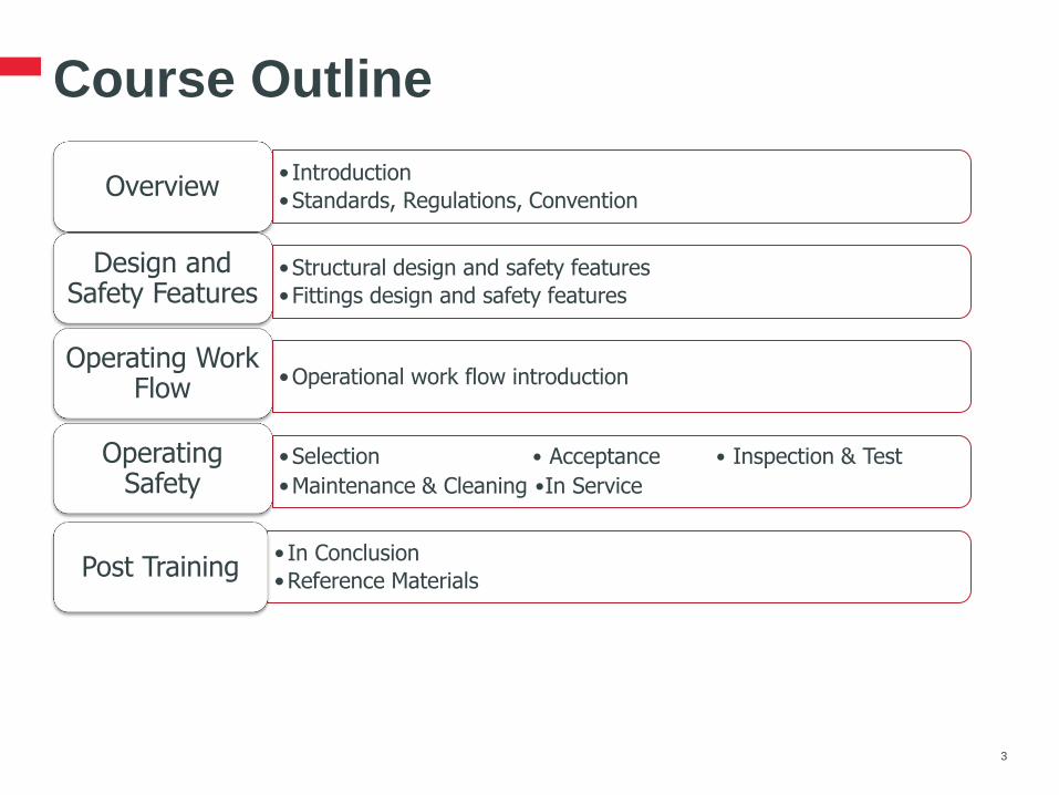
Course Outline
3
• Introduction
•Standards, Regulations, Convention Overview
•Structural design and safety features
•Fittings design and safety features
Design and Safety Features
•Operational work flow introduction Operating Work
Flow
•Selection • Acceptance • Inspection & Test
•Maintenance & Cleaning •In Service
Operating Safety
• In Conclusion
•Reference Materials Post Training
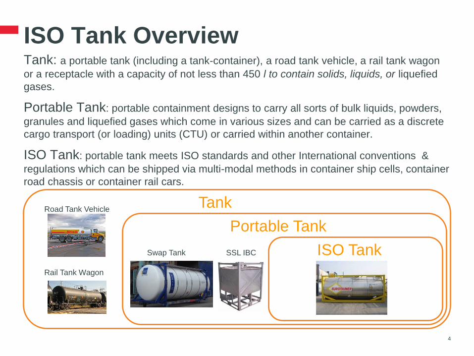
ISO Tank Overview Tank: a portable tank (including a tank-container), a road tank vehicle, a rail tank wagon
or a receptacle with a capacity of not less than 450 l to contain solids, liquids, or liquefied
gases.
Portable Tank: portable containment designs to carry all sorts of bulk liquids, powders,
granules and liquefied gases which come in various sizes and can be carried as a discrete
cargo transport (or loading) units (CTU) or carried within another container.
ISO Tank: portable tank meets ISO standards and other International conventions &
regulations which can be shipped via multi-modal methods in container ship cells, container
road chassis or container rail cars.
4
Road Tank Vehicle
Rail Tank Wagon
Tank
Portable Tank
Swap Tank SSL IBC ISO Tank
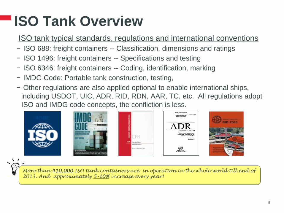
ISO Tank Overview ISO tank typical standards, regulations and international conventions
− ISO 688: freight containers -- Classification, dimensions and ratings
− ISO 1496: freight containers -- Specifications and testing
− ISO 6346: freight containers -- Coding, identification, marking
− IMDG Code: Portable tank construction, testing,
− Other regulations are also applied optional to enable international ships,
including USDOT, UIC, ADR, RID, RDN, AAR, TC, etc. All regulations adopt
ISO and IMDG code concepts, the confliction is less.
5
More than 410,000 ISO tank containers are in operation in the whole world till end of
2013. And approximately 5-10% increase every year!

ISO Tank Overview • ISO tank has same dimensions as GP (general purpose) container according to
ISO 688 with 8’ wide, 8’6” high and different length (10’,20’,30’, 40’, 45’).
• ISO tank have different designed types to carry all sorts of bulk liquids,
powders, granules and liquefied gases with 9,000 to 27,000 liter capacity.
• ISO tank is designed for different dangerous goods transportation.
6
More than 95% of all
ISO tanks built are
20ft long.
14,500 Liter 20’ Liquid ISO
Tank – T11
10’ Liquid ISO Tank – T11
Pressurized Liquefied Gases
ISO Tank – T50
Refrigerated Liquefied Gases
ISO Tank – T75
multiple-element gas
containers (MEGCs) Tank

ISO Tank Overview ISO tank has proper design and fittings for safe operation and transport.
A bird’s eye view of typical liquid ISO tank below.
7
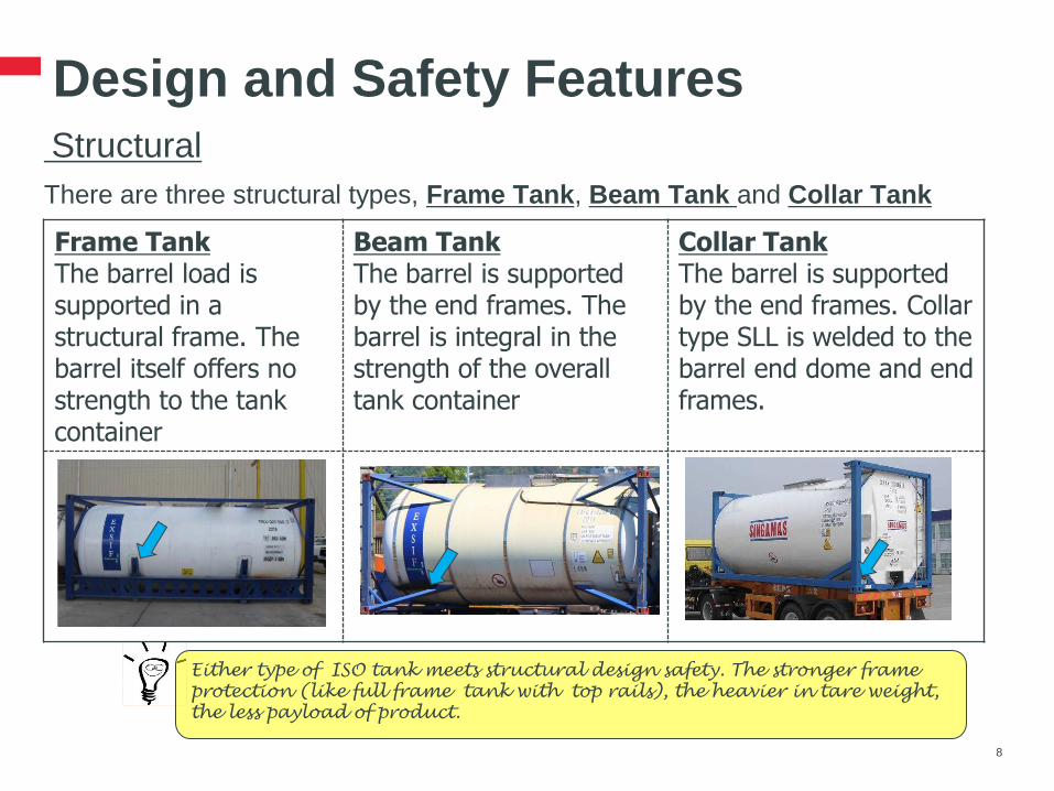
Design and Safety Features Structural
There are three structural types, Frame Tank, Beam Tank and Collar Tank
8
Either type of ISO tank meets structural design safety. The stronger frame
protection (like full frame tank with top rails), the heavier in tare weight,
the less payload of product.
Frame Tank The barrel load is supported in a structural frame. The barrel itself offers no strength to the tank container
Beam Tank The barrel is supported by the end frames. The barrel is integral in the strength of the overall tank container
Collar Tank The barrel is supported by the end frames. Collar type SLL is welded to the barrel end dome and end frames.
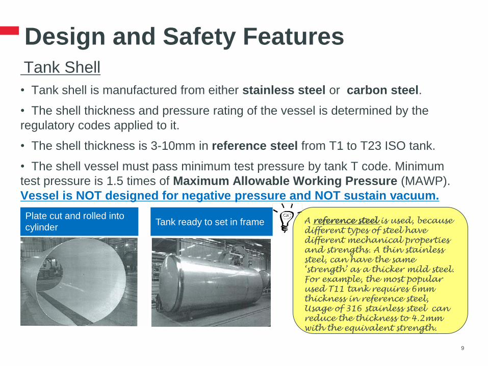
Design and Safety Features Tank Shell
• Tank shell is manufactured from either stainless steel or carbon steel.
• The shell thickness and pressure rating of the vessel is determined by the
regulatory codes applied to it.
• The shell thickness is 3-10mm in reference steel from T1 to T23 ISO tank.
• The shell vessel must pass minimum test pressure by tank T code. Minimum
test pressure is 1.5 times of Maximum Allowable Working Pressure (MAWP).
Vessel is NOT designed for negative pressure and NOT sustain vacuum.
9
A reference steel is used, because
different types of steel have
different mechanical properties
and strengths. A thin stainless
steel, can have the same
‘strength’ as a thicker mild steel.
For example, the most popular
used T11 tank requires 6mm
thickness in reference steel,
Usage of 316 stainless steel can
reduce the thickness to 4.2mm
with the equivalent strength.
Plate cut and rolled into
cylinder Tank ready to set in frame
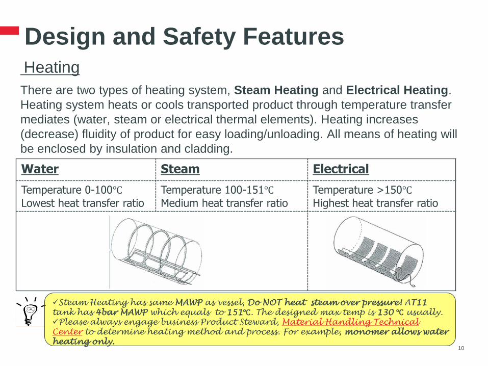
Design and Safety Features Heating
There are two types of heating system, Steam Heating and Electrical Heating.
Heating system heats or cools transported product through temperature transfer
mediates (water, steam or electrical thermal elements). Heating increases
(decrease) fluidity of product for easy loading/unloading. All means of heating will
be enclosed by insulation and cladding.
10
Steam Heating has same MAWP as vessel, Do NOT heat steam over pressure! AT11
tank has 4bar MAWP which equals to 151℃. The designed max temp is 130 ℃ usually.
Please always engage business Product Steward, Material Handling Technical
Center to determine heating method and process. For example, monomer allows water
heating only.
Water Steam Electrical
Temperature 0-100℃
Lowest heat transfer ratio
Temperature 100-151℃
Medium heat transfer ratio
Temperature >150℃
Highest heat transfer ratio

Design and Safety Features Insulation & Cladding
• Insulation is wrapped all around the shell, in order to maintain the product
temperature. The main insulation types are Rockwool and Glass wool. The
thickness of insulation is variable, typically 50-100mm. Thickness of insulation is
one of the factors to impact payload capacity.
• Insulated tank is covered with either a GPR (Glass Reinforced Plastic),
stainless steel or an aluminum cladding jacket to protect any material in contact
with shell and insulation. Cladding should always be sealed and repaired to
prevent the ingress of sea water and other corrosive materials.
11
Rockwool insulation over
aluminum foil barrel
Rockwool insulation over
aluminum foil barrel The cladding / insulation
material is not designed to
withstand a person
standing on it!

Design and Safety Features Man Lid(Manhole, Hatch)
• Opening on top of tank with width no less than 500mm in diameter for
Inspection, Cleaning, Top loading(unloading) operation purpose. Normally located
in central of manlid spill box on top of ISO tank.
• Various types of gasket e.g. PTFE or rubber are used to seal the manlid.
Tanktyt is a Fort Vale gasket of PTFE covering a nitrile rubber core for Nitrogen
blanket or pressurized cargo ‘Gas tight’ purpose.
12
Standard 500mm, 8 point swing bolt manlid.
For Liquid ISO tank typically. Flanged bolt down manlid 20 points.
For pressurized liquified gas ISO tank typically.

Design and Safety Features Pressure Relief Valves(PRV) - Liquid
• PRV’s or SRV’s (Safety Relief Valves) are designed to prevent
an explosion by relieving excess pressure which may build up in a tank for a variety of reasons, or
excess pressure both positive and negative, and to provide vacuum-relief in case partial vacuum conditions arise in the shell. The vacuum relief ensures that the tanks will not implode due to low pressure.
• Each PRV inlet shall be situated on top of the shell in a position as near the longitudinal and transverse centre of the shell.
• At least one PRV is required, additional PRV is required provisionally.
• PRV shall set a nominal pressure start to discharge 110% of MAWP normally.
13
Flanged 2½” PRV (4.4bar) Screwed 2½” PRV (4.4bar) Gas Relief Valve

Design and Safety Features Frangible disc & Pressure gauge
• Frangible discs (bursting discs) are fitted to provide
protection to PRV from the corrosive effect of the substances and/or their vapors being
carried, or any other kind of malfunction caused by the cargo
a guarantee that toxic vapors will only be released in extreme conditions
additional security for higher hazard cargoes. Indicate pressure below setting.
• A pressure gauge or suitable tell-tale indicator shall be provided between the
frangible disc and the pressure relief device. The gauge should be read “Zero”.
14
PRV with Frangible
disc and Pressure Gauge Fire retarding gauze (flame trap)
is also one of PRV ancillary fitted
for flammable products per
regulations to stops a fire entering
a tank to ignite the cargo. Usually
on Vacuum SRV.
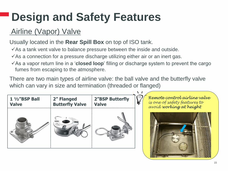
Design and Safety Features Airline (Vapor) Valve
Usually located in the Rear Spill Box on top of ISO tank.
As a tank vent valve to balance pressure between the inside and outside.
As a connection for a pressure discharge utilizing either air or an inert gas.
As a vapor return line in a ‘closed loop’ filling or discharge system to prevent the cargo
fumes from escaping to the atmosphere.
There are two main types of airline valve: the ball valve and the butterfly valve
which can vary in size and termination (threaded or flanged)
15
Remote control airline valve
is one of safety features to
avoid working at height
1 ½”BSP Ball Valve
2” Flanged Butterfly Valve
2”BSP Butterfly Valve
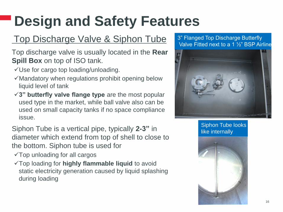
Design and Safety Features Top Discharge Valve & Siphon Tube
Top discharge valve is usually located in the Rear
Spill Box on top of ISO tank.
Use for cargo top loading/unloading.
Mandatory when regulations prohibit opening below
liquid level of tank
3” butterfly valve flange type are the most popular
used type in the market, while ball valve also can be
used on small capacity tanks if no space compliance
issue.
Siphon Tube is a vertical pipe, typically 2-3” in
diameter which extend from top of shell to close to
the bottom. Siphon tube is used for
Top unloading for all cargos
Top loading for highly flammable liquid to avoid
static electricity generation caused by liquid splashing
during loading
16
3” Flanged Top Discharge Butterfly
Valve Fitted next to a 1 ½” BSP Airline
Siphon Tube looks
like internally

Design and Safety Features Spill Box, Drain Tube, Walkway & Handrail
• All above items can be normally found within Spill Box
on top of ISO tank to retain any spills from loading and
unloading process. Centre Spillbox and Rear Spillbox.
• Drain Tube is generally surface mounted on container,
assists with the drainage of rainwater, melt water from
snow, ice and any spilt in the spill box during loading.
• Walkway is usually perforated aluminum plate for access
and operate on top of ISO tank. Walkway and supporting
structure are lightweight and only designed to support two
persons. Walkway configurations vary from very small
length to full coverage. Full Walkway is recommended for
increasing stringent working at height restrictions.
• Collapsible Handrail is optional fitted that fold down
within ISO dimensions. It should NOT be a safe means of
Working at Height, but merely as guide to edge of the
vehicle or ISO tank and driver moving forward on it.
17
Drain Tube
Spill box
Handrail
Walkway

Design and Safety Features Top view of ISO Tank
18
PRV
Manlid
Airline
Full
Walkway
Provision
Outlets
Frame
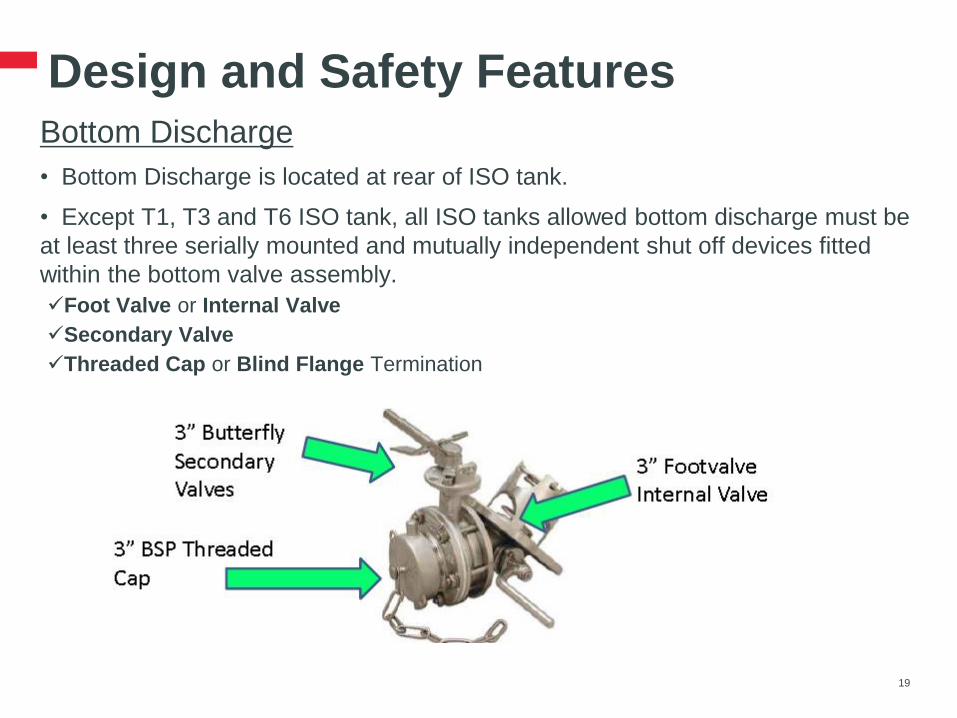
Design and Safety Features Bottom Discharge
• Bottom Discharge is located at rear of ISO tank.
• Except T1, T3 and T6 ISO tank, all ISO tanks allowed bottom discharge must be
at least three serially mounted and mutually independent shut off devices fitted
within the bottom valve assembly.
Foot Valve or Internal Valve
Secondary Valve
Threaded Cap or Blind Flange Termination
19
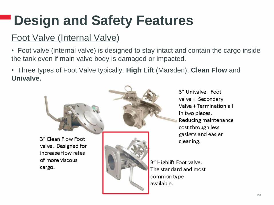
Design and Safety Features Foot Valve (Internal Valve)
• Foot valve (internal valve) is designed to stay intact and contain the cargo inside
the tank even if main valve body is damaged or impacted.
• Three types of Foot Valve typically, High Lift (Marsden), Clean Flow and
Univalve.
20
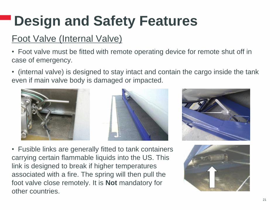
Design and Safety Features Foot Valve (Internal Valve)
• Foot valve must be fitted with remote operating device for remote shut off in
case of emergency.
• (internal valve) is designed to stay intact and contain the cargo inside the tank
even if main valve body is damaged or impacted.
21
• Fusible links are generally fitted to tank containers
carrying certain flammable liquids into the US. This
link is designed to break if higher temperatures
associated with a fire. The spring will then pull the
foot valve close remotely. It is Not mandatory for
other countries.
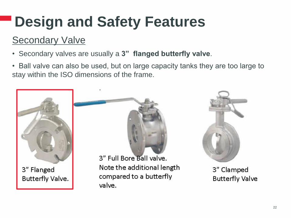
Design and Safety Features Secondary Valve
• Secondary valves are usually a 3” flanged butterfly valve.
• Ball valve can also be used, but on large capacity tanks they are too large to
stay within the ISO dimensions of the frame.
22

Design and Safety Features Threaded Cap or Blind Flange Termination
• A valve termination is what the hose used to empty or fill the tank connects to.
• Threaded valve terminations are BSP, NPT, RJT, ACME. The ‘Male’ thread on
the ISO tank, must match the ‘Female’ thread on the customers hose.
• Bind Flanged valve terminations are either ANSI or DIN. Flanges are bolted
together with customer hose. No “Male”, “Female” differentiation.
• 3” BSP with cap is the most common in the industry. NPT is more common in
the US.
23
3”BSP Male
Termination
3”BSP Female
Cap
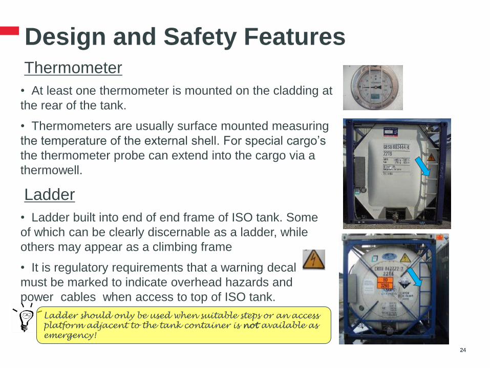
Design and Safety Features Thermometer
• At least one thermometer is mounted on the cladding at
the rear of the tank.
• Thermometers are usually surface mounted measuring
the temperature of the external shell. For special cargo’s
the thermometer probe can extend into the cargo via a
thermowell.
24
Ladder
• Ladder built into end of end frame of ISO tank. Some
of which can be clearly discernable as a ladder, while
others may appear as a climbing frame
• It is regulatory requirements that a warning decal
must be marked to indicate overhead hazards and
power cables when access to top of ISO tank.
24
Ladder should only be used when suitable steps or an access
platform adjacent to the tank container is not available as
emergency!

Design and Safety Features Heating Termination
Steam heating system has Steam Outlet and Steam Inlet
at rear of ISO tank, 1” BSP treaded cap usually.
25
Earthing Connection
Cargo which is flammable or susceptible to ignition from
static electricity, must be capable of being electrically
earthed during operations. A designed Earthing
Connection point at rear of ISO tank should be
connected to a suitable ground point.
25
Documentation Box
A Documentation Box is usually attached with frame of
ISO tank for documents accompany with transport, such
as MSDS, Tremcard, etc. as optional.
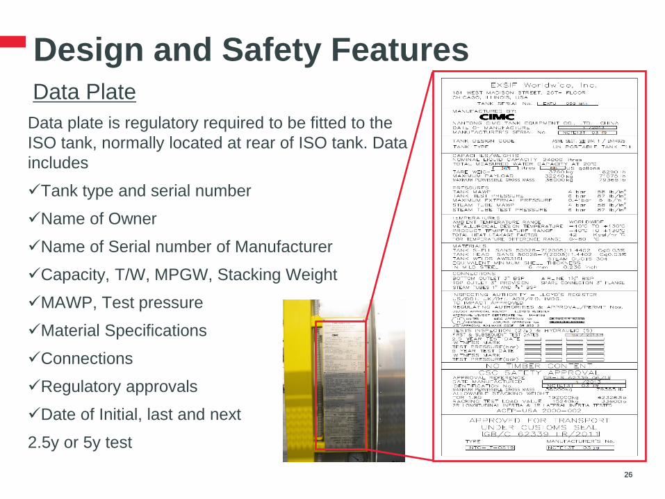
Design and Safety Features Data Plate
Data plate is regulatory required to be fitted to the
ISO tank, normally located at rear of ISO tank. Data
includes
Tank type and serial number
Name of Owner
Name of Serial number of Manufacturer
Capacity, T/W, MPGW, Stacking Weight
MAWP, Test pressure
Material Specifications
Connections
Regulatory approvals
Date of Initial, last and next
2.5y or 5y test
26 26

Design and Safety Features Rear view of ISO Tank
27 27
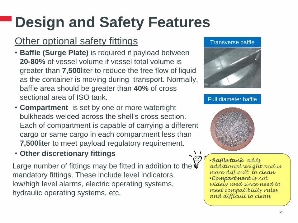
Design and Safety Features Other optional safety fittings • Baffle (Surge Plate) is required if payload between
20-80% of vessel volume if vessel total volume is
greater than 7,500liter to reduce the free flow of liquid
as the container is moving during transport. Normally,
baffle area should be greater than 40% of cross
sectional area of ISO tank.
• Compartment is set by one or more watertight
bulkheads welded across the shell’s cross section.
Each of compartment is capable of carrying a different
cargo or same cargo in each compartment less than
7,500liter to meet payload regulatory requirement.
• Other discretionary fittings
Large number of fittings may be fitted in addition to the
mandatory fittings. These include level indicators,
low/high level alarms, electric operating systems,
hydraulic operating systems, etc.
28 28
Transverse baffle
Full diameter baffle
Baffle tank adds
additional weight and is
more difficult to clean
Compartment is not
widely used since need to
meet compatibility rules
and difficult to clean
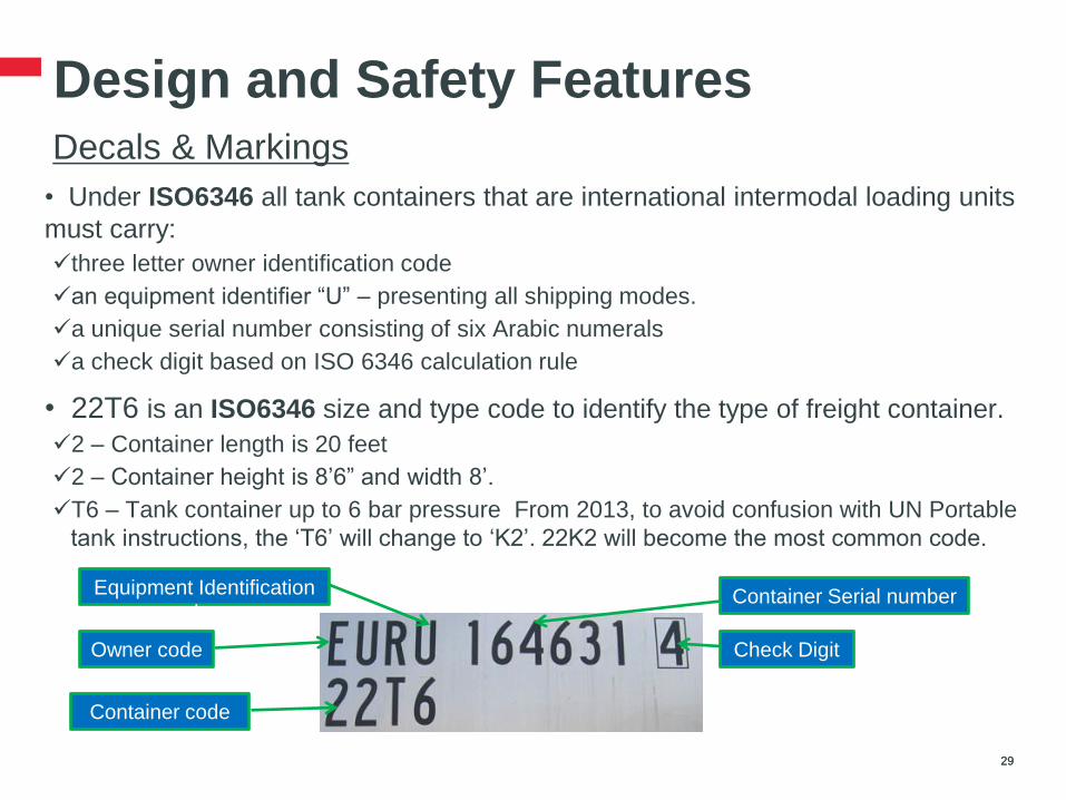
Design and Safety Features Decals & Markings
• Under ISO6346 all tank containers that are international intermodal loading units
must carry:
three letter owner identification code
an equipment identifier “U” – presenting all shipping modes.
a unique serial number consisting of six Arabic numerals
a check digit based on ISO 6346 calculation rule
• 22T6 is an ISO6346 size and type code to identify the type of freight container.
2 – Container length is 20 feet
2 – Container height is 8’6” and width 8’.
T6 – Tank container up to 6 bar pressure From 2013, to avoid confusion with UN Portable
tank instructions, the ‘T6’ will change to ‘K2’. 22K2 will become the most common code.
29 29
Container Serial number Equipment Identification
doe
Owner code Check Digit
Container code

Design and Safety Features Decals & Markings
• ISO tank also complies with other international conventions and region(country)
regulation, decals and markings must be in place accordingly
30 30
RID / ADR – approved for European Rail and Road.
AAR 600 – approved for America Rail
UN PORTABLE TANK – UN of transport is met
TC IMPACT APPROVED - has been impact tested
according to Transport Canada (TC) regulations
‘IC 70’ - meets ISO 1496 and UIC 592-2
(International Union of Railway), 70 is the UK.
Super Heavy Triangle - Maximum Gross Weight
>30480kg and < 34000kg according to UIC
2.6m 8’6” - Height decal at least 8’ (2438mm) high.
24cbm / 4 Bar MAWP – Liquid Capacity and
Maximum Allowable Working Pressure
L4BN - ADR code for EU domestic transport
T11 – UN portable tank code

Coffee Break
31 31
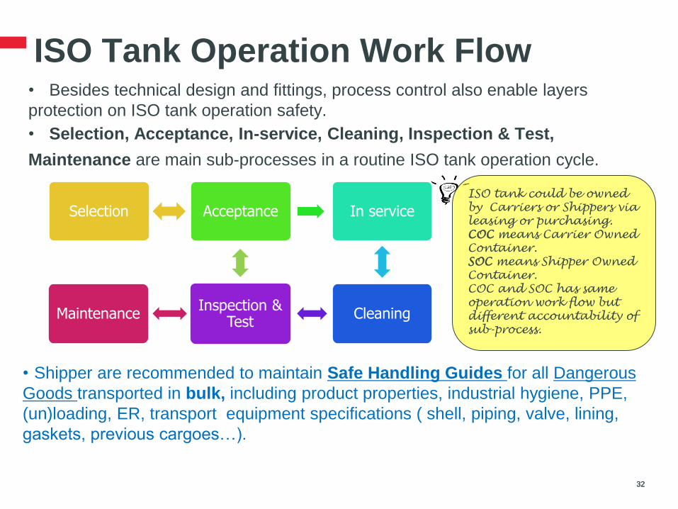
ISO Tank Operation Work Flow • Besides technical design and fittings, process control also enable layers
protection on ISO tank operation safety.
• Selection, Acceptance, In-service, Cleaning, Inspection & Test,
Maintenance are main sub-processes in a routine ISO tank operation cycle.
32 32
Selection Acceptance In service
Cleaning Inspection &
Test Maintenance
ISO tank could be owned
by Carriers or Shippers via
leasing or purchasing.
COC means Carrier Owned
Container.
SOC means Shipper Owned
Container.
COC and SOC has same
operation work flow but
different accountability of
sub-process.
• Shipper are recommended to maintain Safe Handling Guides for all Dangerous
Goods transported in bulk, including product properties, industrial hygiene, PPE,
(un)loading, ER, transport equipment specifications ( shell, piping, valve, lining,
gaskets, previous cargoes…).

ISO Tank Operating Safety Selection
Several factors need to be considered to select ISO tank, besides business safe
handling guides:
• Tank type determination – T code and Tank special provision (TP) could
be found in IMDG Dangerous Goods List according to cargo hazardous
classification, it will determine shell thickness, minimum test pressure, bottom
opening allowance, etc…
• Tank Size determination – determine tank size per degree of filling and
order size
• Compatibility check – cargo reactivity check against previous (last) cargo,
adjacent cargo, transport equipment cargo contact with ( shell, pipe, gasket…).
• Fittings check – validate specific product and source/customer needs to
determine fitting devices, such as type and size of connections, siphon tube,
insulation thickness, heating system, baffle, pressure gauge…
33 33
Fitting requirements really depend on product handling requirements by
business and operational requirements from sources and customers.
Sometime, modification to existing ISO tank is necessary, and it takes time
and cost.

ISO Tank Operating Safety Selection - ISO tank type determination
Step 1 – find out UN number and Packaging group code in product MSDS
section 14th
34 34
Step 2 – determine Tank T code (13) and Special provision (14) from IMDG
Dangerous Goods List
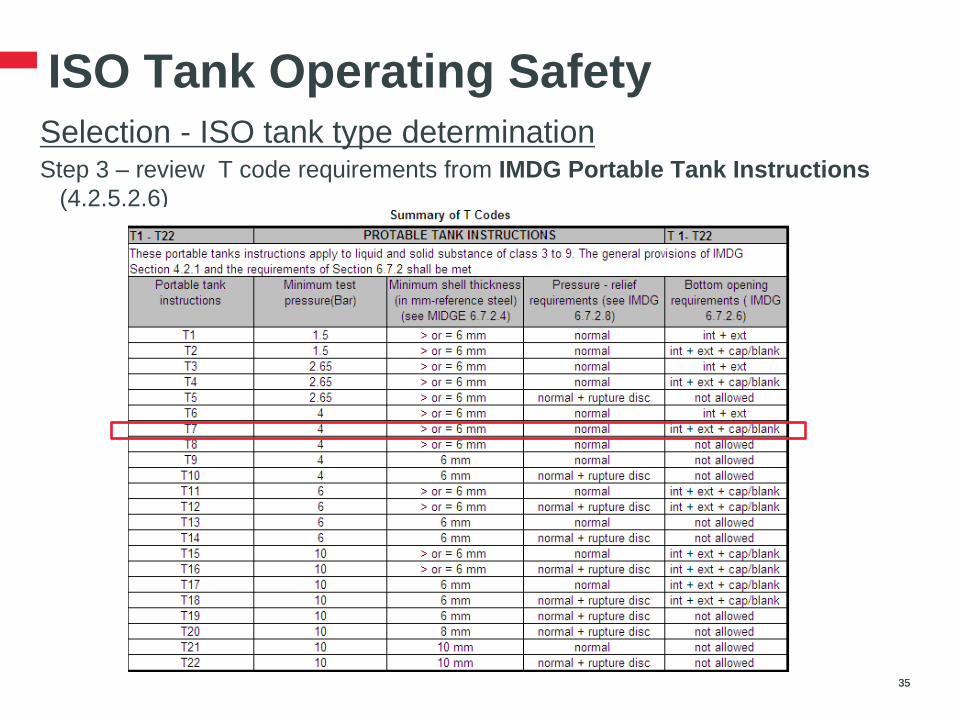
ISO Tank Operating Safety Selection - ISO tank type determination
Step 3 – review T code requirements from IMDG Portable Tank Instructions
(4.2.5.2.6)
35 35
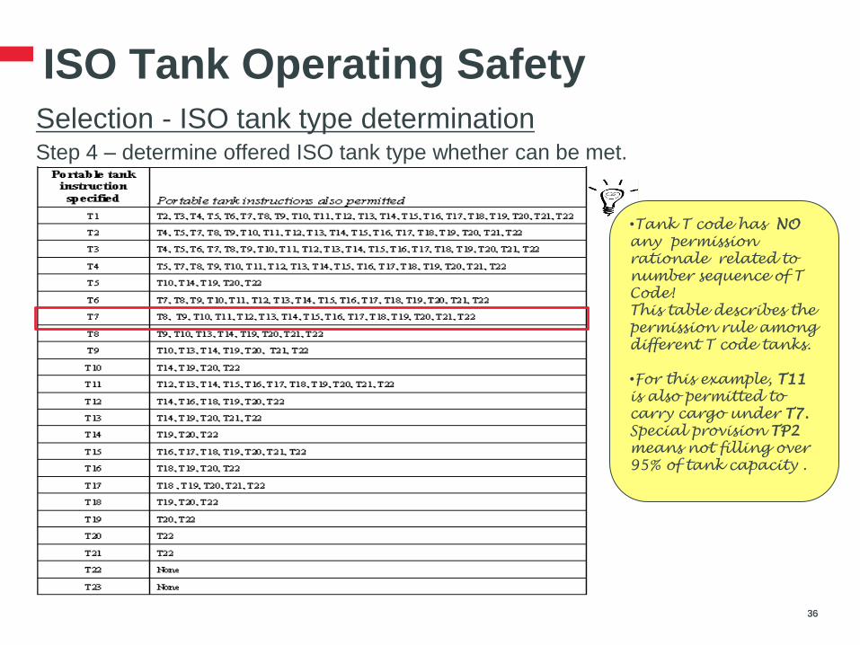
ISO Tank Operating Safety Selection - ISO tank type determination
Step 4 – determine offered ISO tank type whether can be met.
36 36
•Tank T code has NO
any permission
rationale related to
number sequence of T
Code!
This table describes the
permission rule among
different T code tanks.
•For this example, T11
is also permitted to
carry cargo under T7.
Special provision TP2
means not filling over
95% of tank capacity .
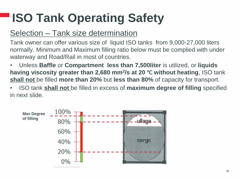
ISO Tank Operating Safety Selection – Tank size determination
Tank owner can offer various size of liquid ISO tanks from 9,000-27,000 liters
normally. Minimum and Maximum filling ratio below must be complied with under
waterway and Road/Rail in most of countries.
• Unless Baffle or Compartment less than 7,500liter is utilized, or liquids
having viscosity greater than 2,680 mm2/s at 20 ℃ without heating, ISO tank
shall not be filled more than 20% but less than 80% of capacity for transport.
• ISO tank shall not be filled in excess of maximum degree of filling specified
in next slide.
37 37
Max Degree
of filling

ISO Tank Operating Safety Selection – Tank size determination
• Formula 1 - Maximum degree of filling for liquid of Not Regulated and
General other than specified in formula 2
Degree of filling = 97% / 1 + α (tr – tf)
• Formula 2 - Maximum degree of filling for liquids of – class 6.1 and 8 (packing groups I and II) and liquid vapor pressure more than 1.75 bar
@ 65 ℃,
– marine pollutant
Degree of filling = 95% / 1 + α (tr – tf)
tf = temperature of the liquid during filling (in℃)
tr = maximum temperature of the liquid during transport (in℃)
α = coefficient of cubical expansion of the liquid
38 38
ISO Tank Operating Safety Compatibility Check – Previous (last) & adjacent cargo
Cargo to be loaded may react with previous cargo or cargo in adjacent
compartment by either substance mixture or temperature impact potentially, even
the equipment is stated clean and ready to serve. It may damage the product and
equipments, or cause severe reactive incident in the worst situation. Compatibility
check is important step to prevent reactive incident.
Several ways to determine the compatibility of previous & adjacent cargo
• Coast Guard Chart
• CRW (Chemical Reactive Worksheet)
• Birdwell Chart
• HM-183
• EPA Chart
• MSDS section 10th – Stability and Reactivity, there is an Incompatible
Materials list prohibited .
39 39

ISO Tank Operating Safety Compatibility Check – Transport equipments
Cargo to be loaded is possible to react / corrode vessel shell, pipes, internal
lining, valves, seals, gaskets, damages the equipments and causes safety
incident also, if it is incompatible.
Several ways to determine compatibility against transport equipments
• IMDG Tank Special Provisions (TP) regarding to compatibility limitation to
containment material and lubricant
• MSDS Section 7th – Handling & Storage, it will advice containment material
limitation.
• MSDS section 10th – Stability and Reactivity, there is an Incompatible
Materials list prohibited for material contact with
40 40

ISO Tank Operating Safety Acceptance
After ISO tank selection, it is recommended to check ISO tank On-Hire Condition
to make sure ready in service.
• Last valid Periodic Inspection Report
• On-Hire Survey Report
• Cleanliness Certificate
ISO tank should be rejected if any failure identified during On Hire Condition
check process. Re-inspection or re-test shall be carried out after reparation,
maintenance or re-cleaning completion.
.
41 41
•This practice is normally applied to ISO tank Off-Hire
process also, to align with return acceptance from tank
owners.
•On hire survey and cleaning survey must be carried
AFTER tank modification per customer requests.

ISO Tank Operating Safety Inspection & Test
Initial, Midway (2.5-year) , Full Period (5-year) inspection & test must be carried
out according to IMDG, ADR, RID, CSC regulations.
Examination items below:
42 42
Initial Midway (2.5-year)
Full Period (5-year)
Design characteristics √
Internal √ √ √
External √ √ √
Fittings √ √ √
Pressure test √ √
•Initial inspection report is usually provided by tank
manufacturer. Midway and Full period inspection report is
usually provided by tank owner, which is conducted by an
independent 3rd
party surveyor.
•Filled tank inspection is allowed to exceed the last
periodic inspection expiration date with in three months
•ACC (Acceptable Container Condition) rule might be
utilized by tank owners and users
ISO Tank Operating Safety Inspection & Test
On-Hire Survey Report, Cleanliness Certificate are commonly used as industrial
practice between tank owners and tank users for hand over.
ACC (Acceptable Container Condition) Manual, developed by ITCO
(International Tank Container Organization), is popularly used as industrial
guidance for operation safety purpose.
43 43
ISO Tank Operating Safety Inspection & Test
• Fair Ware and Tear is defined in ACC manual, which is the age-related
deterioration of the container or any of its component parts while being properly
maintained and used for its intended purpose. Cost of Fair Ware & Tear is under
tank owners.
• Any deterioration resulting from improper use, improper maintenance or lack of
maintenance is not 'Fair Wear and Tear.‘
• Replacement of leaking or contaminated seals and gaskets is a normal operating
requirement and is not 'Fair Wear and Tear.‘
• Cleanliness Certificate is a must to be carried out to prove the specific ISO
tank is Clean, Dry and Odor Free.
44 44
•There is no clear specification of Cleanliness under IMDG, CSC. ACC manual
provides guidance on cleanliness acceptance conditions on Interior, Exterior and
Foreign Marks.
•Cleanliness Certificate is issued by individual 3rd
party surveyors. In some
circumstances, Cleanliness Certificate could include additional inspection
requirements from tank users, such as
Concentration of specific substance
Blanked pressure (Nitrogen, Air)
Cleaning process supervision…

ISO Tank Operating Safety Maintenance & Cleaning
• ISO tank Maintenance and Cleaning are performed at Tank Cleaning
Stations, which are usually granted by Tank owners and 3rd party surveyors.
Tank users could also involve Tank Cleaning Stations nomination per customer
special provisions.
• Other ISO tank operation activities also can be performed at Tank Cleaning
Stations, such as heating, modification…
45 45
• Considering the reality of
developing market, DOW
encourages tank cleaning service
providers to implement cardinal
rules mentioned in next slides as
fundamental elements in the
assessment (self or independent).
Cardinal Rules for Tank Cleaning
Legal Compliance
1. The assessed company and its employees shall obtain all applicable
licenses, permits, certificates, assessment reports per regulatory
requirements and in current valid period, which include but not limit to
• Business license;
• Environment assessment report;
• Pollution discharge permit (if applicable);
• Fire acceptance report;
• Special work certificate, e.g. crane/boiler operator (if applicable);
2. The assessed company shall have all obligatory insurances and keep
in valid period, which include but not limit to
• Publicity insurance
• Employer liability insurance
• Pollution liability insurance (if applicable)
46

Cardinal Rules for Tank Cleaning
Management System
1. Organization chart shall show individuals' roles and link to
responsibilities of the work carried. The company shall have formally
designated a Safety & Health Manager, an Environmental Manager, a
Security Manager and a Quality Manager. The roles can be part-time
or full time depending on company size.
2. Policies and procedures are being executed effectively with traceable
records in reasonable retention period.
47

Cardinal Rules for Tank Cleaning
Management System (cont.)
3. The company shall have effective policies or procedures, including;
• Chemical hazardous awareness, identification and risk analysis;
• Personal Protection Equipment usage policy or procedure;
• Specific product cleaning or heating procedures and agreed by customers
prior to operation;
• Task based work safety procedure, e.g. work at height, confined space,
hot work (if applicable);
• Container hand-over and inspection procedures;
• Waste treatment procedures;
• Comprehensive Emergency Response Plan with drill test at least
annually;
• Training program covering policies and procedures above by roles or by
tasks
48
Cardinal Rules for Tank Cleaning
Hardware Design and Usage
1. The site shall have proper security hardware ( i.e. fences, supervised
barriers, CCTV, gate registration ) to control accessibility.
2. The working and storage area shall have liquid tight ground and
proper containment to prevent pollution to earth, rivers or vegetation.
3. Explosive proof equipment, lightening protection and grounding
system must be used in electric classified area.
4. Ventilation system must be in place in cleaning workshop if exposure
limits reached.
49

Cardinal Rules for Tank Cleaning
Hardware Design and Usage (cont.)
5. A waste collection, recycling, treatment and dispose system shall be
in place and controlled effectively within permitted quota limits.
6. Critical equipment and spare parts shall be installed, operated in
sound and serviceable condition, mandatory inspection and
calibration shall be in place, including but not limit to
• Firefighting system;
• Energy resources;
• Repair workshops;
• Cleaning workshops;
• Waste treatment system;
• Container storage area.
50
Cardinal Rules for Tank Cleaning
Operation Safety and Quality
1. Last cargo must be checked against Material Safety Data Sheet and
confirm with customers on reactive compatibility prior to operation.
2. Site Personal Protection Equipment and other safe ground rules shall
be always followed.
3. Container hand-over inspection shall follow ACC (Acceptable
Container Condition) Manual.
4. Unless customer specified otherwise, tank in-service acceptance
condition shall be granted by 3rd party well known surveyor
companies, including but not limit to
• On Hire Survey Report;
• Cleanliness Certificate to ensure Clean, Dry and Odor Free
51
Cardinal Rules for Tank Cleaning
Operation Safety and Quality (Cont.)
5. Work at height shall be restricted in area with fence securing or
personal life arrest system.
6. Confined Space entry ground rules must be followed: – Only authorized person;
– Test Oxygen (19.5-23.5%) before and during entry;
– Test flammable gas < 10% of Low Explosive Limits if applicable;
– Test toxic gas < Exposure Limits if applicable;
– All required PPE shall be properly worn according to hazards identification;
– Whole attendance to monitor by standby person;
– Rescue Plan is available.
7. Energy resources usage shall be properly locked or Isolated to
prevent person exposure to hazardous conditions.
52

Cardinal Rules for Tank Cleaning
Operation Safety and Quality (Cont.)
8. Unless customer specified otherwise, tank maintenance and
periodic test shall be conducted in a mutual agreed cleaning
station by well known 3rd party survey companies and tank
owners.
9. Pharmaceutical or food or feed grade tank shall be cleaned in an
isolated cleaning bays with dedicated equipment and qualified
utilities.
53

ISO Tank Operating Safety In Service
ISO tank under tank users’ custody for operation after hand over from tank
owners is In Service status. There are operation safety guidance regarding to
specific individual In Service steps need to be considered below generally:
Lifting
Stacking &Stowage
Carrying
Loading & Unloading
Sealing
Placard, UN mark, PSN
54 54
ISO Tank Operating Safety In Service - Lifting
• Lifting equipments shall meet proper design standard fit for lift, such as crane,
super stacker, large forklift, etc.
• Risk assessment must be conducted prior to lifting operation, depends on
equipment lifting weight/height limitation, handling area limitation, and other
surrounding factors. Driver must be trained accordingly.
• General safety rules:
ISO tank without forklift pocket is prohibited to be lifted by forklift
End frame attachments should not be used to lift ISO tank
Use of side frames for all loaded tank lifting is prohibited
ISO Tank may be lifted by slings but the lifting equipment should
be of such design that there is a vertical force at the corner fittings
55 55

ISO Tank Operating Safety In Service – Stacking & Stowage
• ISO tank storage terminals should develop effective emergency response plan
All life saving and fire fighting equipment should be kept in good order and periodically
inspected and their inspection recorded
Appropriate containment should be effective as part of emergency response plan in case
of leakage.
• ISO tank must be stowed and segregated according to IMDG stowage &
segregation principles and other relevant regulations.
• A stacking plan should be developed based on risk assessment criteria below
General stacking consideration – see next slide in details
Ground surface – sustainable weight limitation
Surroundings – distance from buildings, pedestrians, allowable room to maneuver
Local weather conditions – effects of strong wind
Stacking equipment – equipment handling weight and height limitation
Other considerations – Accessibility, Stability, Visibility, Human factors…
56 DOW RESTRICTED 56
Empty ISO tanks containing dangerous residuals and have not been cleaned must be
declared as EMPTY UNCLEANED or RESIDUE LAST CONTAINED under the provisions of
the IMDG Code
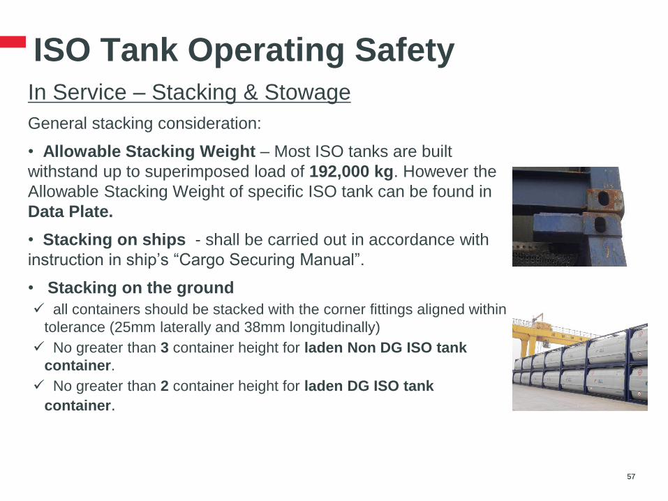
ISO Tank Operating Safety In Service – Stacking & Stowage
General stacking consideration:
• Allowable Stacking Weight – Most ISO tanks are built
withstand up to superimposed load of 192,000 kg. However the
Allowable Stacking Weight of specific ISO tank can be found in
Data Plate.
• Stacking on ships - shall be carried out in accordance with
instruction in ship’s “Cargo Securing Manual”.
• Stacking on the ground
all containers should be stacked with the corner fittings aligned within
tolerance (25mm laterally and 38mm longitudinally)
No greater than 3 container height for laden Non DG ISO tank
container.
No greater than 2 container height for laden DG ISO tank
container.
57 57

ISO Tank Operating Safety In Service – Carrying
The chassis carrying ISO tank shall have special attentions besides general
chassis inspection criteria:
• Frames of ISO tank not exceeds chassis fleet all dimensions to prevent ISO
tank damage by collision. Additional length to prevent rear collision is
recommended.
• Twist locks and Supporting legs must be well functioned and inspected
properly to carry the super heavy tank
• Low centre of gravity design is recommended to minimize surging degree
58 58
ISO Tank Operating Safety In Service – Loading & Unloading
Several pre-cautions suggest to be considered for (un)loading operations
specific for ISO tank:
• Personal Protection Equipment
• Working at Height
• (Un)Loading Scheme
• Coupling and Hoses
Other safety considerations, like Roles & Responsibilities, Emergency
Response Plan, BBS, SQAS, SULID, etc…are general, not specific safety
precautions for ISO tank loading and unloading operations.
Please refer to details in CEFIC (The European Chemical Industry Council)
Best Practices
59 59
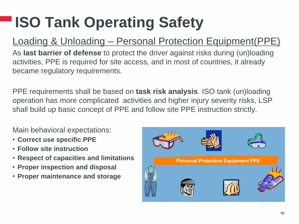
ISO Tank Operating Safety Loading & Unloading – Personal Protection Equipment(PPE)
As last barrier of defense to protect the driver against risks during (un)loading
activities, PPE is required for site access, and in most of countries, it already
became regulatory requirements.
PPE requirements shall be based on task risk analysis. ISO tank (un)loading
operation has more complicated activities and higher injury severity risks, LSP
shall build up basic concept of PPE and follow site PPE instruction strictly.
Main behavioral expectations:
• Correct use specific PPE
• Follow site instruction
• Respect of capacities and limitations
• Proper inspection and disposal
• Proper maintenance and storage
60 60

ISO Tank Operating Safety Loading & Unloading – Personal Protection Equipment(PPE)
PPE usage chapter recommendations of CEFIC.
Note: This chapter covers only general PPE requirements. For specific products (e.g. class 8 or 6.1) and/or for specific
chemical plant environments, additional specific PPE may be required in accordance with risk assessments.
61 61

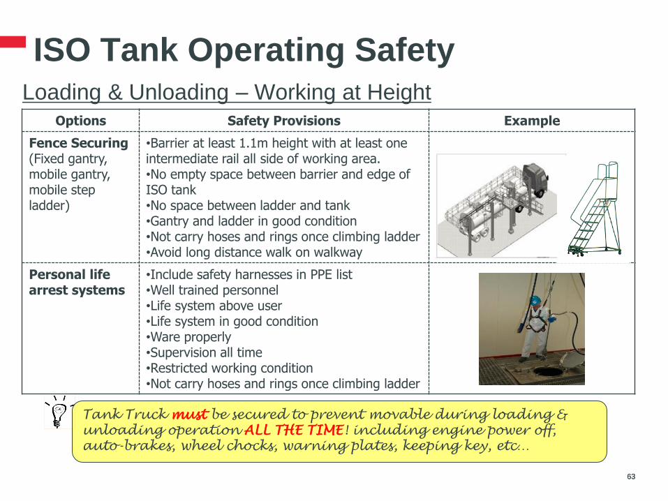
ISO Tank Operating Safety Loading & Unloading – Working at Height
Working at height is regulatory requirements in most of countries. Definition may
be vary by country. Working at top of ISO tank on land (>8.6 feet) or on chassis
(>14 feet) is definitely Working at Height.
Main working at height principles are
• Try to avoid by alternative solutions
• Risk assessment by tasks
• LSP follow site instructions
62 62
If there are no appropriate tools
available and a safe working
environment is not guaranteed, the
driver must stop the activity and
contact his management!
ISO Tank Operating Safety Loading & Unloading – Working at Height
63 63
Options Safety Provisions Example
Fence Securing (Fixed gantry, mobile gantry, mobile step ladder)
•Barrier at least 1.1m height with at least one intermediate rail all side of working area. •No empty space between barrier and edge of ISO tank •No space between ladder and tank •Gantry and ladder in good condition •Not carry hoses and rings once climbing ladder •Avoid long distance walk on walkway
Personal life arrest systems
•Include safety harnesses in PPE list •Well trained personnel •Life system above user •Life system in good condition •Ware properly •Supervision all time •Restricted working condition •Not carry hoses and rings once climbing ladder
Tank Truck must be secured to prevent movable during loading &
unloading operation ALL THE TIME! including engine power off,
auto-brakes, wheel chocks, warning plates, keeping key, etc…
ISO Tank Operating Safety Loading & Unloading – Working at Height
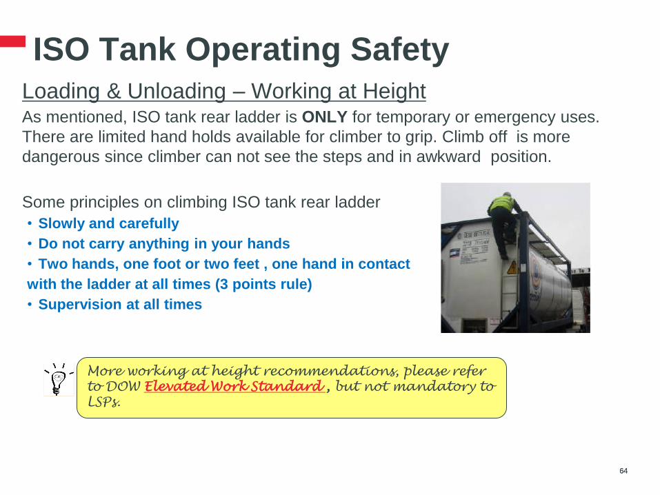
As mentioned, ISO tank rear ladder is ONLY for temporary or emergency uses.
There are limited hand holds available for climber to grip. Climb off is more
dangerous since climber can not see the steps and in awkward position.
Some principles on climbing ISO tank rear ladder
• Slowly and carefully
• Do not carry anything in your hands
• Two hands, one foot or two feet , one hand in contact
with the ladder at all times (3 points rule)
• Supervision at all times
64 64
More working at height recommendations, please refer
to DOW Elevated Work Standard , but not mandatory to
LSPs.
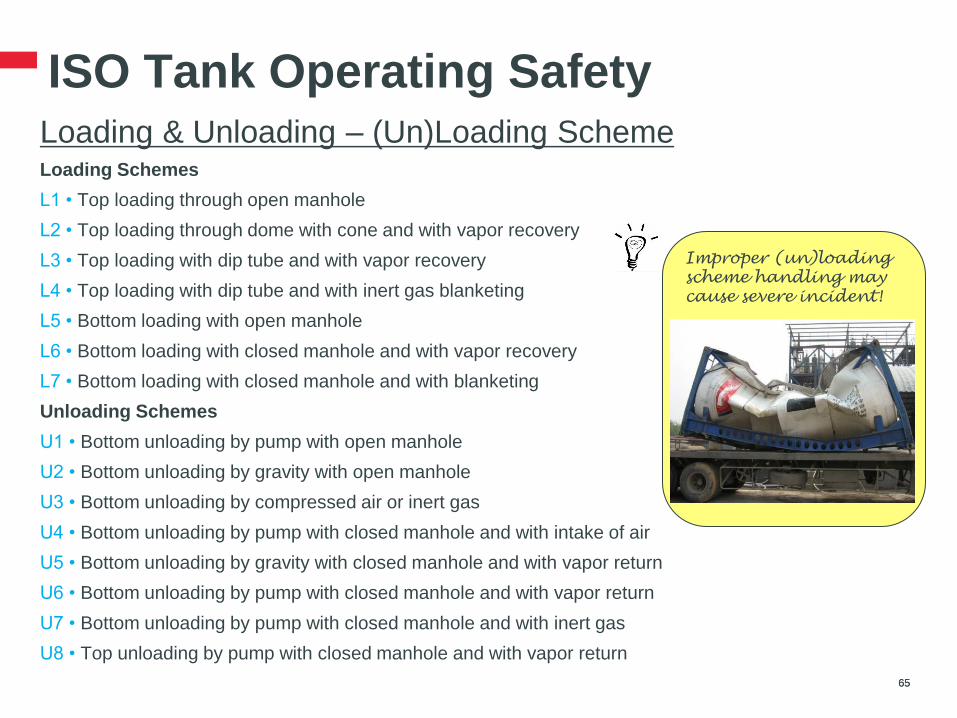
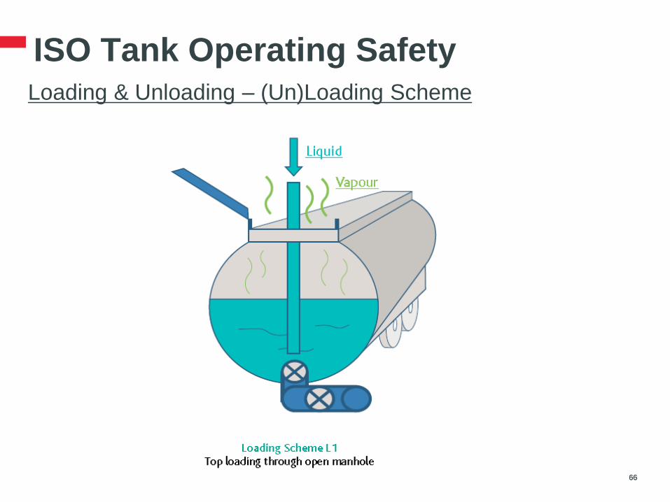
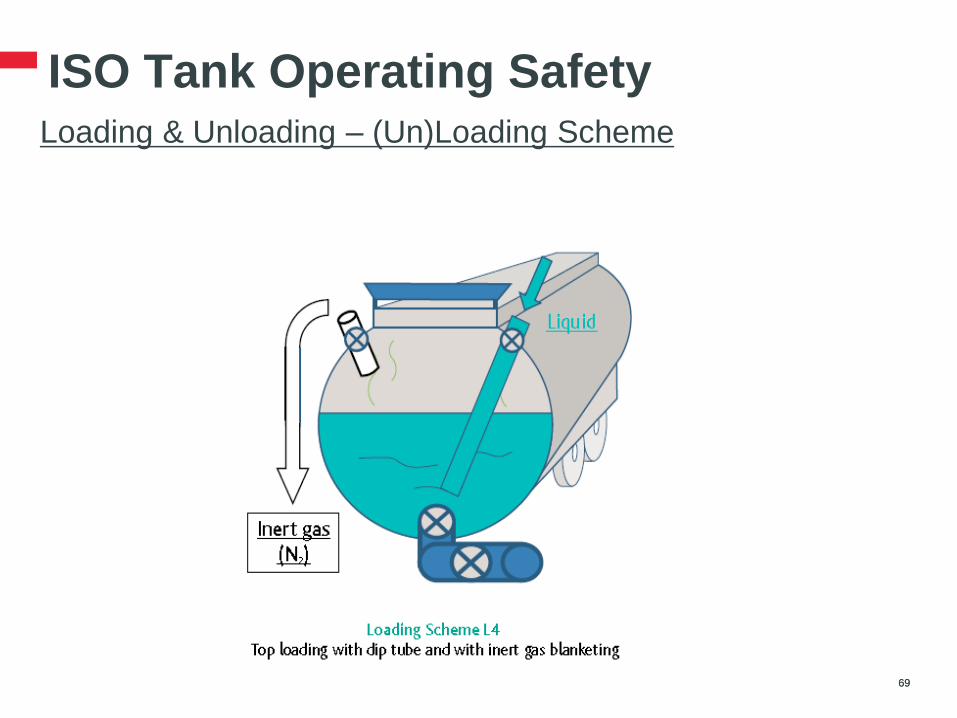
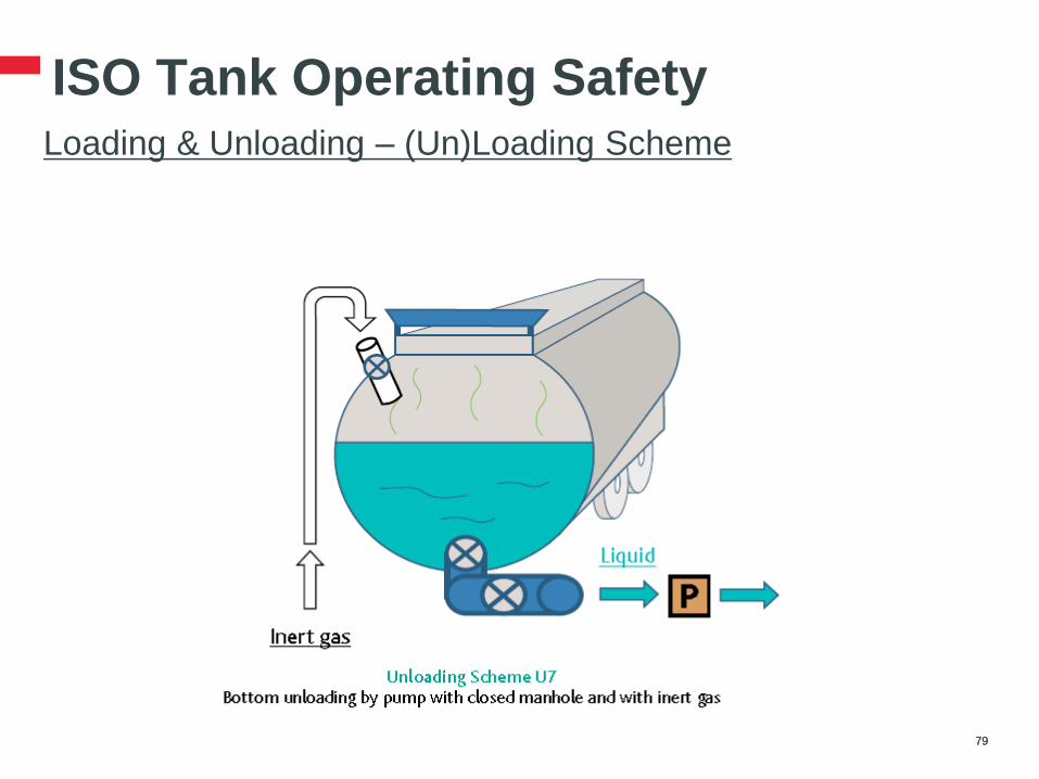
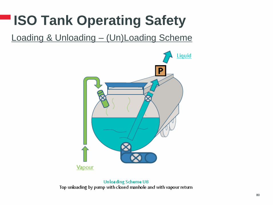
ISO Tank Operating Safety Loading & Unloading – (Un)Loading Scheme
Loading Schemes
L1 • Top loading through open manhole
L2 • Top loading through dome with cone and with vapor recovery
L3 • Top loading with dip tube and with vapor recovery
L4 • Top loading with dip tube and with inert gas blanketing
L5 • Bottom loading with open manhole
L6 • Bottom loading with closed manhole and with vapor recovery
L7 • Bottom loading with closed manhole and with blanketing
Unloading Schemes
U1 • Bottom unloading by pump with open manhole
U2 • Bottom unloading by gravity with open manhole
U3 • Bottom unloading by compressed air or inert gas
U4 • Bottom unloading by pump with closed manhole and with intake of air
U5 • Bottom unloading by gravity with closed manhole and with vapor return
U6 • Bottom unloading by pump with closed manhole and with vapor return
U7 • Bottom unloading by pump with closed manhole and with inert gas
U8 • Top unloading by pump with closed manhole and with vapor return
65 65
Improper (un)loading
scheme handling may
cause severe incident!
ISO Tank Operating Safety Loading & Unloading – (Un)Loading Scheme
66 66

ISO Tank Operating Safety Loading & Unloading – (Un)Loading Scheme
67 67

ISO Tank Operating Safety Loading & Unloading – (Un)Loading Scheme
68 68
ISO Tank Operating Safety Loading & Unloading – (Un)Loading Scheme
69 69

ISO Tank Operating Safety Loading & Unloading – (Un)Loading Scheme
70 70
ISO Tank Operating Safety Loading & Unloading – (Un)Loading Scheme
71 71

ISO Tank Operating Safety Loading & Unloading – (Un)Loading Scheme
.
72 72
ISO Tank Operating Safety Loading & Unloading – (Un)Loading Scheme
73 73

ISO Tank Operating Safety Loading & Unloading – (Un)Loading Scheme
74 74
ISO Tank Operating Safety Loading & Unloading – (Un)Loading Scheme
75 DOW RESTRICTED 75
ISO Tank Operating Safety Loading & Unloading – (Un)Loading Scheme
76 76

ISO Tank Operating Safety Loading & Unloading – (Un)Loading Scheme
77 77

ISO Tank Operating Safety Loading & Unloading – (Un)Loading Scheme
78 78
ISO Tank Operating Safety Loading & Unloading – (Un)Loading Scheme
79 79
ISO Tank Operating Safety Loading & Unloading – (Un)Loading Scheme
80 80

ISO Tank Operating Safety Loading & Unloading – (Un)Loading Scheme
Except PPE and Working at Height, other main risks of different scheme
81 DOW RESTRICTED 81
ISO Tank Operating Safety Loading & Unloading – (Un)Loading Scheme
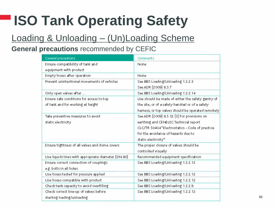
General precautions recommended by CEFIC
82 DOW RESTRICTED 82

ISO Tank Operating Safety Loading & Unloading – (Un)Loading Scheme
Specific precautions by scheme recommended by CEFIC
83 DOW RESTRICTED 83
ISO Tank Operating Safety Loading & Unloading – (Un)Loading Scheme
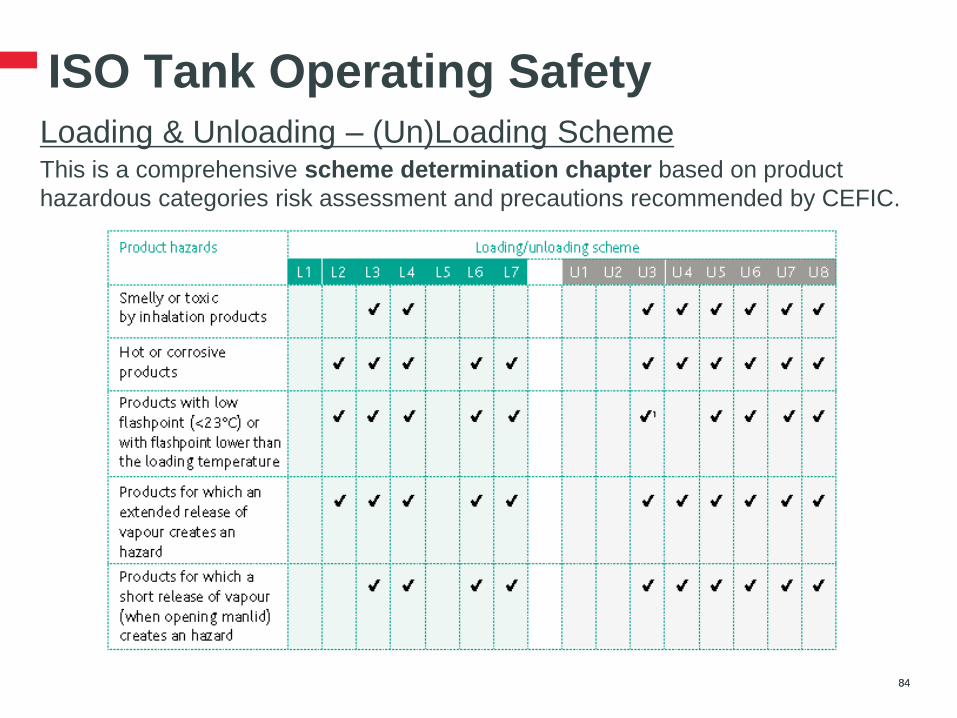
This is a comprehensive scheme determination chapter based on product
hazardous categories risk assessment and precautions recommended by CEFIC.
84 84
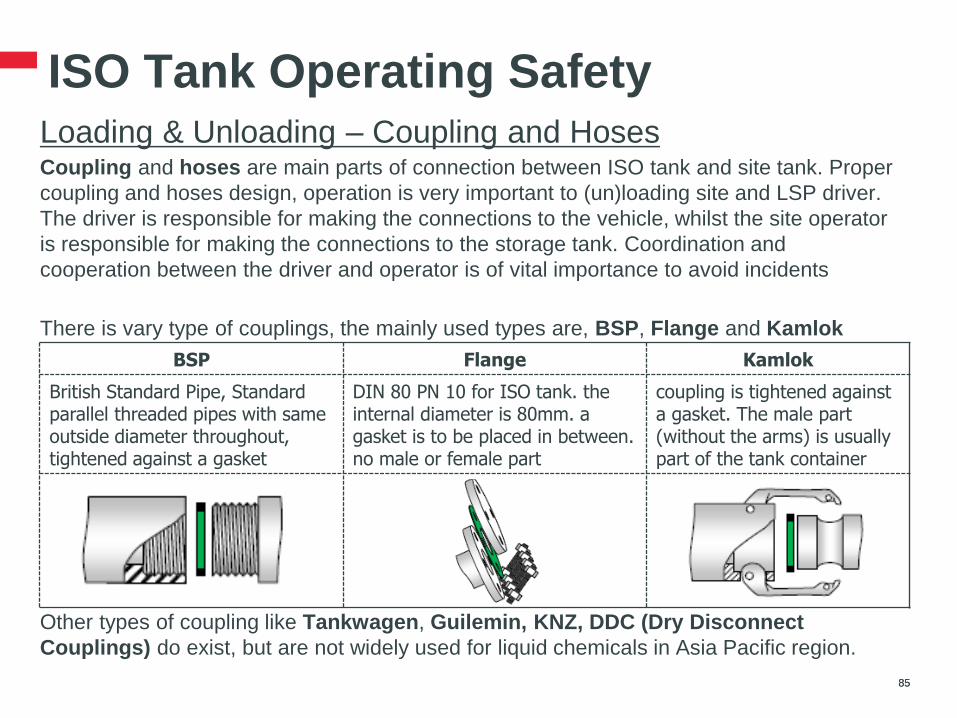
ISO Tank Operating Safety Loading & Unloading – Coupling and Hoses
Coupling and hoses are main parts of connection between ISO tank and site tank. Proper
coupling and hoses design, operation is very important to (un)loading site and LSP driver.
The driver is responsible for making the connections to the vehicle, whilst the site operator
is responsible for making the connections to the storage tank. Coordination and
cooperation between the driver and operator is of vital importance to avoid incidents
There is vary type of couplings, the mainly used types are, BSP, Flange and Kamlok
Other types of coupling like Tankwagen, Guilemin, KNZ, DDC (Dry Disconnect
Couplings) do exist, but are not widely used for liquid chemicals in Asia Pacific region.
85 85
BSP Flange Kamlok
British Standard Pipe, Standard parallel threaded pipes with same outside diameter throughout, tightened against a gasket
DIN 80 PN 10 for ISO tank. the internal diameter is 80mm. a gasket is to be placed in between. no male or female part
coupling is tightened against a gasket. The male part (without the arms) is usually part of the tank container
ISO Tank Operating Safety Loading & Unloading – Coupling and Hoses
86 86
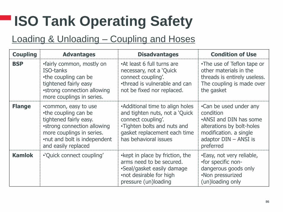
Coupling Advantages Disadvantages Condition of Use
BSP •fairly common, mostly on ISO-tanks •the coupling can be tightened fairly easy •strong connection allowing more couplings in series.
•At least 6 full turns are necessary, not a ‘Quick connect coupling’. •thread is vulnerable and can not be fixed nor replaced.
•The use of Teflon tape or other materials in the threads is entirely useless. The coupling is made over the gasket
Flange •common, easy to use •the coupling can be tightened fairly easy. •strong connection allowing more couplings in series. •nut and bolt is independent and easily replaced
•Additional time to align holes and tighten nuts, not a ‘Quick connect coupling’. •Tighten bolts and nuts and gasket replacement each time has behavioral issues
•Can be used under any condition •ANSI and DIN has some alterations by bolt-holes modification. a single adaptor DIN – ANSI is preferred
Kamlok •‘Quick connect coupling’
•kept in place by friction, the arms need to be secured. •Seal/gasket easily damage •not desirable for high pressure (un)loading
•Easy, not very reliable, •for specific non-dangerous goods only •Non pressurized (un)loading only
ISO Tank Operating Safety Loading & Unloading – Coupling and Hoses
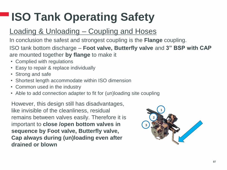
In conclusion the safest and strongest coupling is the Flange coupling.
ISO tank bottom discharge – Foot valve, Butterfly valve and 3” BSP with CAP
are mounted together by flange to make it • Complied with regulations
• Easy to repair & replace individually
• Strong and safe
• Shortest length accommodate within ISO dimension
• Common used in the industry
• Able to add connection adapter to fit for (un)loading site coupling
87 87
1
2
3
However, this design still has disadvantages,
like invisible of the cleanliness, residual
remains between valves easily. Therefore it is
important to close /open bottom valves in
sequence by Foot valve, Butterfly valve,
Cap always during (un)loading even after
drained or blown

ISO Tank Operating Safety Loading & Unloading – Coupling and Hoses
There are less chances to request LSPs to carry hoses for (un)loading
connection. This shall try to avoid because it needs extended responsibilities to
LSPs on hose management like connection, maintenance, whilst reduces
payload.
General principals are:
• Annual testing and visual inspection
• Proper material made of and design to resist pressure, temperature and
compatible with product
• Proper marking, indicating
• Proper working, cleaning, inspection, maintenance instruction
88 88
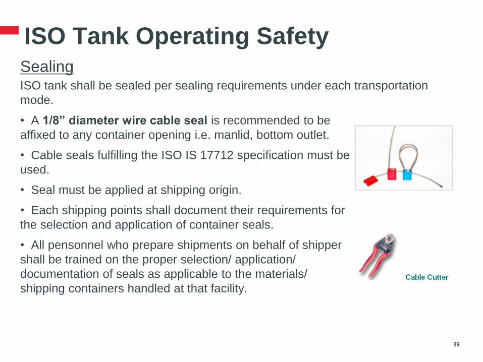
ISO Tank Operating Safety Sealing
ISO tank shall be sealed per sealing requirements under each transportation
mode.
89 89
• A 1/8” diameter wire cable seal is recommended to be
affixed to any container opening i.e. manlid, bottom outlet.
• Cable seals fulfilling the ISO IS 17712 specification must be
used.
• Seal must be applied at shipping origin.
• Each shipping points shall document their requirements for
the selection and application of container seals.
• All pensonnel who prepare shipments on behalf of shipper
shall be trained on the proper selection/ application/
documentation of seals as applicable to the materials/
shipping containers handled at that facility.

ISO Tank Operating Safety Placard, UN marks, Proper Shipping Name (PSN)
Placard, UN marks, PSN ( can be found in MSDS section 14th) shall be affixed to
exterior surface of ISO tank according to applicable transport regulations.
90 90
Here is the general highlights of IMDG placard, UN marks, PSN principles:
• Previous placards, marks and signs shall be removed
• Placard must be clearly displayed each side
• Placard size no less than 250mm, with a line same color as symbol 12.5mm inside the edge
• Proper Shipping Name shall be durably marked on at least both sides
• UN number marks shall be displayed in black digits not less than 65mm high, either
against white background in the lower half of each primary placard, or
on orange rectangular panel not less than 120mm high, 300mm wide, adjacent to placard
3082
3082
Environmentally Hazardous
Substance, Liquid, N.O.S (1,2-
Benzisothiazol-3(2H)-one)
Environmentally Hazardous
Substance, Liquid, N.O.S (1,2-
Benzisothiazol-3(2H)-one)
Or
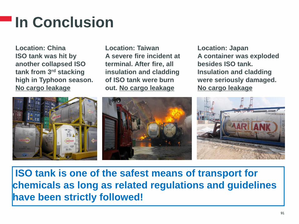
In Conclusion
91 91
ISO tank is one of the safest means of transport for
chemicals as long as related regulations and guidelines
have been strictly followed!
Location: China
ISO tank was hit by
another collapsed ISO
tank from 3rd stacking
high in Typhoon season.
No cargo leakage
Location: Japan
A container was exploded
besides ISO tank.
Insulation and cladding
were seriously damaged.
No cargo leakage
Location: Taiwan
A severe fire incident at
terminal. After fire, all
insulation and cladding
of ISO tank were burn
out. No cargo leakage
Reference Materials
92 92
• DOW Supply Chain Material Handling Technical Center
• IMDG code – International Marine Dangerous Goods code
• ISO – International Standard Organization
• CEFIC – Transport & Logistics of The European Chemical
Industry Council
• ITCO – International Tank Container Organization
Also thanks for ISO tank training materials shared from ISO
tank owners (EUROTAINER, EXSIF, DAELIM)!
FAQ
93 93
Further Questions?