iso 9001: 2008 certified as9100 certified mil-p-50884e...
TRANSCRIPT

1705 Cannon LaneNorthfield, MN 55057
1.877.663.7162FAX 507.663.1070
E-mail information@all� exinc.comwww.all� exinc.com
ISO 9001: 2008 Certified
AS9100 Certified
MIL-P-50884E Qualified
RoHS Compliant
ITAR Registered
UL Recognized
IPC Member
Flexible Circuit & Heater Design Guide
Flexible Circuit & Heater Design Guide
www.all� exinc.com
Download from our website: www.all� exinc.com
ISO 9001: 2008 • AS9100 • MIL-P-50884E • ITAR Registered • RoHS Compliant • UL Recognized • IPC Member

ALL FLEX • 1-877-663-7162 • www.allfl exinc.com1
BENEFITS OF FLEXIBLE CIRCUITRY ........................................................................................................................2Bene� ts, Advantages, and FeaturesALL FLEX’S STANDARD CAPABILITIES ............................................................................................................... 3 - 4Design Considerations and Manufacturing CapabilitiesStandard MaterialsSINGLE-SIDED AND DOUBLE-SIDED CIRCUIT CONSTRUCTION ..................................................................................5Cross Sectional View, FeaturesWhen to Use Single-Sided and Double-Sided FlexMULTI-LAYER AND RIGID FLEX CIRCUIT CONSTRUCTION .........................................................................................6When to Use Multi-Layer and Rigid-FlexMAXI-FLEX® ........................................................................................................................................................7Features of these exceptionally long circuits 40'+FLEXIBLE HEATER CIRCUITS .............................................................................................................................8-11Flexible Heater and Hybrid HeatersADDED VALUE CAPABILITIES ............................................................................................................................12Automated Pick and Place, Circuit Testing and Potted CircuitsSURFACE DIELECTRICS OPTIONS .........................................................................................................................13CoverlaysLiquid Photoimageable SoldermaskDESIGN GUIDELINES .....................................................................................................................................14-15Conductor Pad Design- Fillets, Tie-Downs, and Annular RingsShaved and Elongated Pads, Radiused Traces, and I-BeamSHIELDING ..................................................................................................................................................16-17Solid Copper, Cross Hatched CopperConductive SilverConductive Shielding FilmStripline Impedance ChartRIGIDIZERS/STIFFENERS ....................................................................................................................................18FR4, Polyimide, and PolyesterTERMINATION METHODS ...................................................................................................................................19ZIF End and Surface MountAll Flex FingersADDITIONAL TECHNICAL INFORMATION ....................................................................................................... 20 - 22Typical Properties of Dielectric MaterialsCurrent Carrying Capabilities and Current Rating NomographIPC Speci� cation ListCOMPUTER AIDED DESIGN (CAD) INFORMATION ..................................................................................................23Design/Data Transfer InformationGLOSSARY ........................................................................................................................................................24REQUEST FOR QUOTE WORKSHEET .................................................................................................................25-26
TABLE OF CONTENTS

ALL FLEX • 1-877-663-7162 • www.allfl exinc.com 2
1. A SOLUTION TO A PACKAGING PROBLEM.
• Flexible circuits allow unique designs which solve interconnection problems.
• The ability to fold and form fl ex circuits enables a package size reduction.
• Flex circuits make installation and repair practical and cost e� ective.
2. REDUCE ASSEMBLY COSTS.
• Flex circuits can be tested prior to assembly of components.
• Reduction of connectors and solder joints lower costs.
3. REPLACEMENT FOR A CIRCUIT BOARD AND WIRES.
• Flexible circuits simplify system design.
• Flex reduces the number of levels of interconnection required in an electronic package.
• Flexible circuits eliminate human error common in wire assemblies as routing is determined by artwork and repeatability is guaranteed.
4. REDUCE WEIGHT AND SPACE.
• Considerable weight reduction is a bene� t over wire harnesses, and rigid assemblies.
• Thickness can be as thin as .004 inches (.10mm) in total.
5. DYNAMIC FLEXING.• The thinness of the material makes
fl exible circuits the best candidate for fl exible applications up to millions of fl exures.
6. THERMAL MANAGEMENT/HIGH TEMPERATURE APPLICATIONS.
• Flex circuits dissipate heat at a better rate than any other dielectric materials.
7. AESTHETICS.• Flex circuits improve the internal
appearance of an electronic package, which can have an infl uence on the decision making process of prospective users of the product.
BENEFITS OF FLEXIBLE CIRCUITRY

ALL FLEX • 1-877-663-7162 • www.allfl exinc.com3
CIRCUIT CONSTRUCTIONS:SINGLE-SIDED
DOUBLE-SIDED
MULTI-LAYER
RIGID FLEX
SHIELDING:COPPER
TATSUTA, SILVER STANDARD CIRCUIT SIZES:(Longer available, considered MAXI-Flex®)
SINGLE-SIDED: up to 22" by 28" (558.8mm by 711.2mm)
DOUBLE-SIDED: up to 16" by 22" (406.4mm by 588.8mm)
MAXI-FLEX®: up to 20" by 40' plus(508mm by Length)
MULTI-LAYER:12" by 24" (304.8mm by 609.6mm)
RIGID FLEX: 6-8 Layers standard construction
(depending on complexity and design)
HOLE SIZE:NON-PLATED (Standard Processing) THRU HOLES:
.005" (.125mm) min. drilled hole size. Tolerance +/- .0015" (.038mm)
PLATED THRU HOLE: .005" (.125mm) min. drilled hole size. Tolerance +.003" (.076mm), -.005" (.125mm)
(Smaller holes can be manufactured, contact All Flex Sales)
LINE WIDTH AND SPACING:.004" (.1mm) MINIMUM LINE
.004" (.1mm) MINIMUM SPACING
(Finer lines can be manufactured, contact All Flex Sales.)
CIRCUIT/BLANKING CONSIDERATIONS:SOFT TOOLING:
Outline dimensions +/- .005" (.125mm)
Radius of inside corners minimum of .023" (.584mm)
Edge insulation .010" min (.254mm)
HARD TOOLING: Outline dimensions +/- .001" (.0254mm)
Edge insulation .006" min (.152mm)
LASER CUT: Outline dimensions +/- .003" (.25mm)
Edge insulation .004" (.102mm)
DRILL POSITION:Tolerance of +/- .003" (.076mm)
ZIF END TOLERANCE: +/- .002" (.0508mm) with CpK>2.0
ADDED VALUE CAPABILITIES• AUTOMATED MIXED FORM
FACTOR ASSEMBLY
• SURFACE MOUNT COMPONENTSDown to 0201
Thru hole assembly (see more on page 10)
• PLACEMENT ACCURACY TO .001"
• RoHS COMPLIANT ASSEMBLY
• PRECISION STENCILING
• HEAT SINKS
• ELECTRICAL TESTING
• FOLDING FORMING
DESIGN CONSIDERATIONS
FOR STANDARD MANUFACTURING CAPABILITIES
Circuit Design and Engineering support will
(inquire within about nonstandard sizes)
ASSIST YOU

ALL FLEX • 1-877-663-7162 • www.allfl exinc.com 4
BASE MATERIALS: Polyimide:
.0005" to .005" (.012mm - .127mm)
Polyester: .002" to .010" (.050mm - .254mm)
Adhesiveless Materials: Copper thickness .5 oz. to 4 oz.
Flame Retardant: Laminates and Coverlay
Other Materials Upon Request
BASE COPPER: .5 oz. - .0007" (.018mm) thick copper
1 oz. - .0014" (.036mm) thick copper
2 oz. - .0028" (.071mm) thick copper
3 oz. - .0042" (.107mm) thick copper
4 oz. - .0056" (.142mm) thick copper
5 oz. - .0070" (.178mm) thick copper
6 oz. - .0084" (.213mm) thick copper
7 oz. - .0098" (.249mm) thick copper
Thicker coppers are available (call for information). See current carrying chart on page 20.
SOLDER MASK: Polyimide coverlay:
.0005" to .005" (.012mm - .127mm)
Polyester coverlay: .0015" to .003" (.038mm - .076mm)
Photo-imageable covercoat: LPI - Liquid Photo Imagable - for high density applications.
SURFACE FINISH: Hot Air Solder Level (HASL)
RoHS Compliant and Tin Lead
Tin Plating (RoHS Compliant)Electroless and electrolytic
Silver (RoHS Compliant)Immersion
Hard Gold over Nickel (RoHS Compliant) (Typically used for contacts)
Soft Gold over Nickel (RoHS Compliant) (Electrolytic - sometimes used for bonding gold wire to the gold layer)
ENIG (Electroless Nickel Immersion Gold) (RoHS Compliant) (Electroless - sometimes used for bonding aluminum wire to the nickel under the gold)
Organic Coating OSP (RoHS Compliant)
RIGIDIZERS/STIFFENERS:FR4-drilled, routed, or scored
Aluminum
Polyimide
Polyester
Stainless Steel
CERTIFICATIONS: ISO 9001: 2008 Certifi ed
AS9100 Certifi ed
MIL-P-50884E Qualifi ed
RoHS Compliant
IPC Member: Product is manufactured in accordance with the requirements of IPC-6013B Classes 1, 2, 3
ITAR Registered
JCP Certifi ed
UL Recognized: for single and double sided constructions with individual polyimide layers up to 5 mil, including several surface � nishes. (File # E161240)
STANDARD MATERIALS

ALL FLEX • 1-877-663-7162 • www.allfl exinc.com5
MULTI-LAYER & RIGID-FLEX CIRCUIT CONSTRUCTION
(refer to standard materials page for material availability)
SINGLE-SIDED & DOUBLE-SIDED CIRCUIT CONSTRUCTION
SINGLE-SIDED FLEXIBLE CIRCUITS
DOUBLE-SIDED FLEXIBLE CIRCUITS
(refer to standard materials page for material availability)
A UNIQUE TYPE OF SINGLE SIDED CIRCUITSCULPTURED FLEX CIRCUITS
Sculptured fl ex circuits have variable copper thicknesses within the part. Thin copper is used for the fl exible regions, and thicker copper is used at the interconnection point. Sculptured fl ex circuits provide bare metal connections and are a highly reliable alternative to mechanically crimped contact pins.
FINGER LENGTH3.175mm ± 0.635mm
1.27mm Ref
0.635mm ± 0.127mm
0.140mm to 0.250mm ± 10%
0.1mm ± 0.025mm
FLEXIBLE REGION INTERCONNECTION POINT
CONDUCTORPITCH ± 0.127mm
Typical Finger
Single-sided fl exible circuits consist of a single conductive layer on a fl exible dielectric fi lm (see diagram below).
SINGLE-SIDED FEATURES:• Very thin construction
.004"-.008" (.10mm - .20mm)• 1 Conductive layer.• Reverse bared or back bared pads, provide
access from both sides of the part.• Supported and unsupported fi nger areas.
WHEN TO USE SINGLE-SIDED FLEX:• Dynamic fl exing applications• Unusual folding and forming applications.• Installation/service applications/repair.• Limitations on space / thickness• Installation / Service fl exing
Double-sided fl exible circuits consist of two conductive layers normally connected with a plated through-hole (see diagram below).
DOUBLE-SIDED FEATURES:• Component assembly available on both sides.• Two conductive layers.
WHEN TO USE DOUBLE-SIDED FLEX:• Required when circuit density and layout can
not be routed on a single layer.• Ground and power plane applications.• Used for shielding applications.• Dense surface mount assembly.

ALL FLEX • 1-877-663-7162 • www.allfl exinc.com 6
MULTI-LAYER & RIGID-FLEX CIRCUIT CONSTRUCTION
MULTI-LAYER & RIGID-FLEX CIRCUIT CONSTRUCTION
RIGIDSECTION
RIGIDSECTION
FLEXSECTION
POLYIMIDE FILM
TOP COVER LAYER
BOTTOM COVER LAYER
0.0014" (1 OZ./SQ. FT) COPPER
0.0014" (1 OZ./SQ. FT) COPPER
0.005" FR-4
0.005" FR-4
0.005" NO FLOW PREPREG
0.005" NO FLOW PREPREG
0.001" ACRYLIC ADHESIVE0.001" POLYIMIDE FILM
0.001" ACRYLIC ADHESIVE0.001" POLYIMIDE FILM
0.0028" (2 OZ./SQ. FT) COPPER
0.0028" (2 OZ./SQ. FT) COPPER
Rigid-Flex circuits are characterized by having conductors on both the fl exible and rigid layers of the circuit. Plated thru holes extend between the fl exible and rigid sections and electrically connect multiple conductor layers. Rigid-fl ex circuits are often used when components are mounted on both sides of the rigid section. This circuit construction is known as a Type 4 circuit as de� ned by IPC 6013 and should be distinguished from a fl exible circuit with a rigid sti� ener attached.
Inquire Within
COPPER
PI (Polyimide)
ADHESIVE ADDED BETWEEN EACH
MULTI-LAYER CONSTRUCTION CIRCUITS • Controlled impedance and shielding possible.
(refer to standard materials page for material availability)
RIGID-FLEX CIRCUITS
WHEN TO USE MULTI-LAYER FLEX:• Required when circuit
density and layout can not be routed on a single or double layer.
• Ground and power plane applications.
• Used for shielding applications.
• Dense surface mount assembly.
• Increased circuit density.
• EMI/RFI shielding.• Controlled impedance
with shielding.

All Flex has trade marked our special fl ex circuit off ering that allows an application to be produced at larger than normal sizes. MAXI-FLEX® is a circuit that is normally found on one or two conductive layers longer than 24" in length. Additional layers may be added.
MAXI-FLEX®
Custom Designed Copper Flexible Circuits in exceptionally long lengths up to 40'+.
• Sizes from 2' to 40'+ by 20" max
• Single-sided, double-sided, multi-layer
• Plated through holes
• Ideal for large systems and unmanned systems
• Permits tight bends
• Eliminates bulky cabling
• For use in military and aerospace applications
• Standard conductor pitch down to 0.030" (0.76mm) (� ner pitch available, call ALL FLEX sales for more information)
• Shielding possible to provide EMI/RFI protection
• Controlled impedance design available
• Light Weight, dense packaging solutions
• Replacement for wire harnesses
• Custom termination design for use with:
High density circular connectors
D subminiature connectors
Surface mount connectors & components
Pin and socket connectors
Leaded components
Edge card and zif connectors
Crimp-on/displacement pins and connectors
MAXI-FLEX® circuits are designed for your speci� c application with signal, power and shielding layers in one complete interconnect package.
(IMPORTANT: DUE TO MATERIAL AVAILABILITY in these lengths, contact All Flex staff for further information on standard MAXI-FLEX® construction.)
MAXI-FLEX®
All Flex is one of the few companies in the world that manufactures fl exible circuits in exceptional lengths over 24".
MAXI-FLEX®
7 ALL FLEX • 1-877-663-7162 • www.allfl exinc.com
MAXI-FLEX®
54"L Maxi-Flex® Circuit

FLEXIBLE HEATER FEATURES:• Temperatures up to:
120°C Polyimide
232°C Silicone Rubber
• Circuit size up to 22" x 30" (558mm x 762mm)
• Resistant to most chemicals
• Engineered to meet specifi ed output
• Flexible Heaters can be supplied as thin as .004"
• Component and connector assembly
• Soldered wire assembly for connections
• Epoxy reinforced soldered wires
• Bifi lar Heater - A heater that consists of two parallel traces of diff ering resistance. User can heat one, the other , or both traces essentially making three heaters in one. Bifi lar heaters can be advantageous if the user wants to keep control logic to a minimum.
OTHER CONSIDERATIONS/ADD ONS:• Thermistor assembly
• Heater can be built with multiple heating zones
• Quick turn available
• Any volume quantities
• Assembly expertise
• Epoxy coated solder joints provide strain relief and insulation and environmental protection
• UL Recognized
(File #E338387)
(Category KSOT2)
• PSA – Pressure Sensitive Adhesive can be applied to either surface for a peel and stick application
• Heat spreaders of aluminum can be applied to the heater to reduce the incidence of hot spots
• Designs can be manufactured to reduce or eliminate heat in certain positions of the heater
• Heaters can be designed/manufactured into virtually any size or shape, with or without clearance holes
• All heaters are custom designed and manufactured to customer specifi cations
• Special marking of part number or image
ALL FLEX HAS THE UNIQUE CAPABILITY TO MANUFACTURE HEATERS AND ASSEMBLE COMPONENTS
All Flex can design, fabricate, and reverse engineer fl exible heaters to meet customer’s exact requirements. Flexible polyimide and silicone rubber heaters and heater component assemblies are fabricated with a variety of metal alloys to deliver custom solutions for heating capacity, watt density, and other application specifi c customer needs. Typical lead times 2 – 3 weeks upon customer approval.
CUSTOM HEATERS FEATURES/ADDED VALUE
All Flex canREVERSE ENGINEERto meet exact requirements
Heaters can be designed and manufactured into virtually any size and shape.
ALL FLEX HAS THE UNIQUE CAPABILITY TO MANUFACTURE HEATERS AND ASSEMBLE COMPONENTS
All Flex can design, fabricate, and reverse engineer fl exible heaters to meet customer’s exact requirements. Flexible polyimide and silicone rubber heaters and heater component assemblies are fabricated with a variety of metal alloys to deliver custom solutions for heating capacity, watt density, and other application specifi c customer needs. Typical lead times 2 – 3 weeks
CUSTOM HEATERS FEATURES/ADDED VALUE
ALL FLEX • 1-877-663-7162 • www.allfl exinc.com 8
FLEXIB
LE HEATER
SFLEX
IBLE H
EATERS
FLEX
IBLE
HEA
TER
S
9 ALL FLEX • 1-877-663-7162 • www.allfl exinc.com
FLEX
IBLE
HEA
TER
S
Now your single or double sided circuit assembly can have built-in heaters.
All Flex can take your electronic circuitry requirements and your heat requirements and create a hybrid product. Typically the heater function is on one side of the base � lm and the electronics function is on the opposite side. By combining a copper layer for the electronics with a layer of resistive metal for the heater, a hybrid circuit can be designed. Top to bottom electrical connection can be done with plated thru holes. All Flex has unique process and materials that can accommodate even the most challenging hybrid requirements.
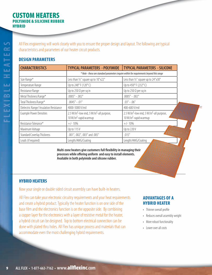
All Flex engineering will work closely with you to ensure the proper design and layout. The following are typical characteristics and parameters of our heater circuit products.
HYBRID HEATERS
DESIGN PARAMETERS
CHARACTERISTICS TYPICAL PARAMETERS - POLYIMIDE TYPICAL PARAMETERS - SILICONE* Note - these are standard parameters inquire within for requirements beyond this range
Size Range* Less than ½" square up to 10"x22" Less than ½" square up to 24"x30"
Temperature Range Up to 248° F (120° C) Up to 450° F (232° C)
Resistance Range Up to 250 Ω per sq in Up to 250 Ω per sq in
Metal Thickness Range* .0005" - .002" .0005" - .002"
Total Thickness Range* .0045" - .01" .03" - .06"
Dielectric Range/ Insulation Resistance 4000-5000 V/mil 400-600 V/mil
Example Power Densities 2.5 W/in2-low end, 5 W/in2-all purpose, 10 W/in2-rapid warmup
2.5 W/in2-low end, 5 W/in2-all purpose, 10 W/in2-rapid warmup
Resistance Tolerance* +/- 10% +/- 10%
Maximum Voltage Up to 115 V Up to 220 V
Standard Coverlay Thickness .001", .002", .003" and .005" .015"
Leads (if required) Length/AWG/Coating Length/AWG/Coating
CUSTOM HEATERSPOLYIMIDE & SILICONE RUBBERHYBRID
Multi-zone heaters give customers full fl exibility in managing their processes while off ering uniform and easy to install elements. Available in both polyimide and silicone rubber.
ADVANTAGES OF A HYBRID HEATER• Thinner overall profi le
• Reduces overall assembly weight
• More robust functionality
• Lower over all costs

FLEXIB
LE HEATER
S
10ALL FLEX • 1-877-663-7162 • www.allfl exinc.com
HEATER APPLICATIONSFLEX
IBLE H
EATERS
HEATER APPLICATIONS
MEDICAL
All Flex heaters provide precise heating and thermal control in applications where thermal management is extremely important.
All Flex Understands:
• Medical quality requirements
• FDA traceability expectations
• Medical device qualifi cation procedures
• Clean room/precision assembly needs of medical customers
• Medical device product development cycles
• Small and medium volume delivery needs
Some Applications:
• Incubator
• Operating room equipment
• Surgical tools
• Defi brillator
• Dialysis equipment
• Blood analysis equipment
• Medical instrumentation and laboratory equipment
AERONAUTICS/AEROSPACE
All Flex is AS9100, ISO 9001:2008 Certifi ed, ITAR Registered, Mil-P-50884E Compliant.
Heating technology is used extensively in the Aeronautics and Aerospace industry due to the temperature extremes and the need for reduced weight and compact electronics. All Flex heaters help to maintain high reliability of electrical components by limiting exposure to high degrees of thermal contraction/expansion cycles.
All Flex Heaters also keep non-electrical components at constant temperatures for both functional and convenience purposes.
The typical application for heaters in this industry is not to heat devices to high temperatures, but to keep devices from getting cold. Our technology enables us to fabricate heaters that remain fl exible and compliant at -55 degrees C (-67 degrees F) while heating to slightly above freezing.
Some Applications:
• Helicopter controls
• Aircraft controls
• De-icing systems
• Satellite hardware
• Cockpit systems
MILITARY/DEFENSEAll Flex is AS9100, ISO 9001:2008 Certifi ed, ITAR Registered, Mil-P-50884E Compliant.
All Flex Heaters provide an excellent solution for high performance, densely packed electronics where space is a premium yet heating of components are needed. Numerous All Flex Flexible Circuits are used by prime contractors, NASA, developmental laboratories, and government agencies.
Some Applications:
• Aircraft equipment
• Night vision
• Sighting systems
• Ruggedized computers
Lab Analysis Heater
ADVANTAGES OF A HYBRID HEATER• Thinner overall profi le
• Reduces overall assembly weight
• More robust functionality
• Lower over all costsBreath Analyzer

FLEX
IBLE
HEA
TER
S
ALL FLEX • 1-877-663-7162 • www.allfl exinc.com11
Our Vision... is to be your
for � ex...
FLEX
IBLE
HEA
TER
SHEATER APPLICATIONS & STOCK HEATERS
OUTDOOR ELECTRONICSDevices and equipment that are exposed to cold temperatures creates design challenges for manufacturers. Typical thermal cycling introduces molecular expansion issues that can impact electronics, cause mechanical wear, introduce moisture variation, restrict moving parts, and other functional and operational problems.
Some Applications:
• Automated Teller Machines
• Outdoor LED and Canister Lighting
• Outdoor LCD Screen
• Ruggedized electronic and computer devices made to operate in extreme weather conditions
GENERAL & INDUSTRIAL ELECTRONICS All Flex Heaters are used in a wide variety of electronic applications to assist in the performance of our customers’ end products.
Some Applications:
• Food service equipment
• Storage tanks
• Battery heaters to enhance battery performance
• Photo processing
• Outdoor antenna
• Hand-held scanners
STOCK HEATERS:(for production products or test/evaluation)
Generally our customers have unique design requirements that necessitate customization for their particular device or application, however one of our standard heaters may meet your needs, All Flex o� ers standard, non-custom fl exible heaters. These heaters are classi� ed as either Stocked or Build to Order (BTO) and are available without a tooling or set-up charge.
Select size/shape, resistance, or watt density (watts per square inch) to determine if a particular stock product meets your needs then assess the additional options below that may be required.
Stocked heaters options:
• Each stocked heater is available with a pressure sensitive back-piece cut to the same size as the heater.
• Aluminum heat-dissipation shield, cut to the same size as the heater.
• Custom marking is available as speci� ed and desired by the customer.
• The addition of wires and associated wire characteristics
• UL Recognition
Visit: WWW.ALLFLEXHEATERS.COM for a complete listing of all standard stock heaters, technical detail, lead times, pricing, option pricing, etc.
All Flex heaters can be supplied with PSA (Pressure Sensitive Adhesive) on the back of the heater with a release liner for easy peel and stick, the PSA makes installation quick and easy.

12ALL FLEX • 1-877-663-7162 • www.allfl exinc.com
All Flex has the capability to quickly design, manufacture and deliver in volumes from prototype to production. All Flex has manufactured hundreds of designs for the military, medical and industrial markets.
HAND ASSEMBLY• Operators certifi ed to J-STD
• Lead and lead free capability
• ESD controls
AUTOMATED PICK AND PLACE CAPABILITY PROVIDES COMPLEX ASSEMBLY COMBINATIONS INCLUDING:• Surface mount components down
to 0201
• Precise vision system allows placement accuracy to .001"
• Fine pitch capability to .5mm pitch
• Leaded devices
• Tactile domes
• Staked terminals
• Unlimited component confi gurations
• RoHS Compliant assembly
• Virtually all SMT components including discretes, SOICs, PLCCs, QPPs, & BGA's
• Auto fi ducial correction
AUTOMATED ASSEMBLY• Solder Screener Automated screening of solder onto
arrays/panels using solder stencil
Lead and lead free capability
• Selective Soldering Automated ability to solder leads on
through hole connector
Lead and lead free capability
OTHER ALL FLEX ADDED VALUE CAPABILITIES• Thru hole assembly• Flexible circuit folding and forming
(see page 13)• Electrical testing• Heat Sinks• Nomenclature Screening• Stiff ener placement• Design and manufacturing
support – concept to completion
CIRCUIT TESTING CAPABILITY• Solderability• Ionic contamination• Dimensional tolerance• Thermal testing• Microsections
POTTED CIRCUITSconnector securely adhered with potting compound to perform in rugged applications where vibration is typical
ALL FLEX ADDS VALUE
CIRCUIT TESTING CAPABILITY• Solderability • Microsections• Ionic contamination • Continuity • Dimensional tolerance • Inductance• Thermal testing • Capacitance• Dielectric net-to-net • Resistance• Insulation resistance (IR) • Impedance
All Flex has the capability to quickly design, manufacture
AUTOMATED PICK AND PLACE CAPABILITY PROVIDES COMPLEX
OTHER ALL FLEX ADDED VALUE CAPABILITIES• Thru hole assembly
ALL FLEX ADDS VALUE
ALL FLEX • 1-877-663-7162 • www.allfl exinc.com13
Surface dielectrics are applied to the outside layers of the circuit to insulate the copper conductors.
Following are types of surface dielectrics used at All Flex.
POLYIMIDE/POLYESTER COVERLAYThese materials are normally produced with a drilling process. Limitations to the drilling process enable production of round and oval holes, leaving the inability to have square openings, dense features or any unique shape other than round or oval. Both polyester and polyimide coverlay can be punched or blanked in lieu of the drilling process and is normally done for large coverlay openings.
VIA HOLE: Covered with coverlay
COMPONENT HOLE: .005" (.127mm) minimum larger than the copper pad
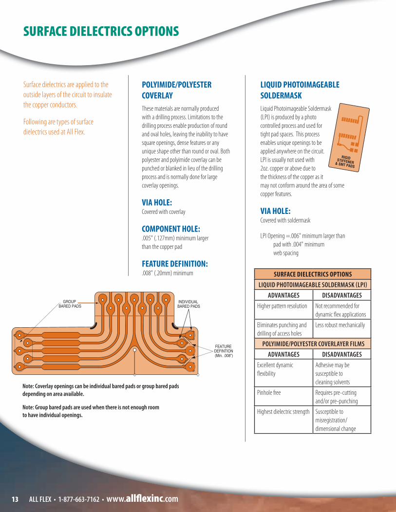
FEATURE DEFINITION: .008" (.20mm) minimum
LIQUID PHOTOIMAGEABLE SOLDERMASKLiquid Photoimageable Soldermask (LPI) is produced by a photo controlled process and used for tight pad spaces. This process enables unique openings to be applied anywhere on the circuit. LPI is usually not used with 2oz. copper or above due to the thickness of the copper as it may not conform around the area of some copper features.
VIA HOLE: Covered with soldermask
LPI Opening =.006" minimum larger than pad with .004" minimum web spacing
Note: Coverlay openings can be individual bared pads or group bared pads depending on area available.
Note: Group bared pads are used when there is not enough room to have individual openings.
SURFACE DIELECTRICS OPTIONS
SURFACE DIELECTRICS OPTIONSLIQUID PHOTOIMAGEABLE SOLDERMASK (LPI)
ADVANTAGES DISADVANTAGESHigher pattern resolution Not recommended for
dynamic fl ex applications
Eliminates punching and drilling of access holes
Less robust mechanically
POLYIMIDE/POLYESTER COVERLAYER FILMSADVANTAGES DISADVANTAGES
Excellent dynamic fl exibility
Adhesive may be susceptible to cleaning solvents
Pinhole free Requires pre-cutting and/or pre-punching
Highest dielectric strength Susceptible to misregistration/dimensional change

ALL FLEX • 1-877-663-7162 • www.allfl exinc.com 14
CONDUCTOR PAD DESIGN:Pads should have tie-downs (also called anchoring spurs or rabbit ears). Tie-downs are captured by the coverlay to anchor the copper to prevent separation between the copper and the base material during assembly.
FILLETING:All pads, on both through-hole and surface mount pads, should be � lleted to reduce stress points. This helps eliminate breaking during fl exing.
DESIGN GUIDELINES:
CONDUCTOR PAD DESIGN AND FILLETING
This section of our guide addresses rules speci� cally pertaining to conductor and pad design recommendations. Due to
the fl exible nature of the material during both manufacturing and application use, the following information is
recommended to produce the highest yielding and best functioning fl exible circuit.
CALCULATING PAD SIZE:Recommended pad size is dependent on the component pad requirement that is speci� c to your application.
FORMULA: HOLE SIZE (FINISHED) + CUSTOMER REQUIRED TOLERANCES + ALL FLEX TOLERANCE = PAD SIZE REQUIRED .030" (.76mm) ±.003" (.07mm) .020" (.50mm) .053" (1.34mm)
LAND PATTERN DESIGN(see IPC-7351)

ALL FLEX • 1-877-663-7162 • www.allfl exinc.com15
RADIUSED TRACES help to alleviate breaking during folding and bending.
I-BEAM constructions occur when the conductors on both layers lie directly on top of each other, increasing the sti� ness of the circuit through fold areas. A better alternative is to stagger conductors, alternating their location to retain the maximum fl exibility of the circuit.
FOLD LINES may be designated by “tick” marks which may be either in the copper layers or silkscreen layers. These features aid in bending and designating bend locations.
CIRCUIT TRACE WIDTH should not change in bend areas and the transition should be at least .030" (.76mm) from the fold line.
BEND RADIUS of a fl ex should be approximately 10 times the material thickness and at least .050" away from the plated through hole.
r=10 x T
BUTTON PLATING/PADS ONLY PLATING is a process that allows for the plated through holes to maintain their connection while the traces are not plated, allowing the circuit to have increased fl exibility.
DESIGN GUIDELINES:
TO INCORPORATE IN BENDING AND FOLDING DESIGNS

ALL FLEX • 1-877-663-7162 • www.allfl exinc.com 16
SOLID COPPER:Solid Copper is the most common method of shielding. Solid copper shields increase the rigidity of the circuit, and should be included in thickness to bend radius ratios. Copper shield can be put on one or both sides of the circuit. Solid copper can also cover selective conductors.
CROSSHATCHED COPPER:Crosshatching is an artwork design that relieves much of the copper shield areas by the use of a pattern. Crosshatching helps the circuit to retain its fl exibility and can be put on one or both sides. Crosshatch shielding can also cover selective conductors.
CONDUCTIVE SILVER:Conductive silver can be substituted for the copper for shielding purposes in some applications. Silver shielding is not recommended for a dynamic fl exing application due to its brittle characteristic, and may be prone to cracking in severe bending applications. Silver can be a solid or crosshatched shield and can be put on one or both sides of the circuit. It can also cover selected conductors only.
CONDUCTIVE SHIELDING FILM:Metalized � lm with a conductive adhesive coating is thermally bonded to fl exible circuitry. Selective openings in the coverlay � lm allow the conductive adhesive to electrically contact the fl ex circuit. This creates a shielding layer by the contact between the metalized � lm and the ground traces.
If your application requires limits in electromagnetic and/or electrostatic interference, shielding may be required. Shields are material around a conductor or group of conductors that limit these factors.
SHIELDING
Note: Additional shielding options exist, such as shielding between circuit conductor.Contact All Flex Staff for further details.

ALL FLEX • 1-877-663-7162 • www.allfl exinc.com17
CHARACTERISTIC IMPEDANCE:Controlled impedance is important in high speed digital circuitry to avoid signal refl ectance and power loss. The impedence of a fl exible printed circuit depends on dielectric constant of the base material, conductor width, conductor thickness and dielectric thickness.
STRIPLINE
SINGLE ENDED MICROSTRIP
MATERIAL THICKNESS INCLUDING ADHESIVE
TRACE WIDTH FOR 50 OHMS IMPEDANCE
1/2 OZ COPPER
TRACE WIDTH FOR 50 OHMS IMPEDANCE
1 OZ COPPER
TRACE WIDTH FOR 75 OHMS IMPEDANCE
1/2 OZ COPPER
TRACE WIDTH FOR 75 OHMS IMPEDANCE
1 OZ COPPER
0.002 0.0036 0.0032 0.0015 >.0010.003 0.0057 0.0053 0.0025 0.00130.004 0.0078 0.0074 0.0035 0.00280.005 0.0102 0.0096 0.0050 0.00410.006 0.0122 0.0117 0.0060 0.00500.007 0.0144 0.0139 0.0070 0.00600.008 0.0166 0.0161 0.0080 0.00680.009 0.0189 0.0184 0.0088 0.00850.010 0.0211 0.0206 0.0105 0.0095
All calculations assume .002 thick coverlayer, 3.4 dielectric constant and 50% trace/ 50% space on di� erential pairs
POLYMIDE COVERLAY
POLYMIDE COVERLAY
POLYMIDE
ADHESIVECOPPER SIGNAL
COPPER REFERENCE PLANE
ADHESIVE
ADHESIVE
SINGLE ENDED MICROSTRIP
SHIELDING
FLEXIBLE POLYIMIDE CIRCUIT – IMPEDANCE REFERENCE CHART
T=COPPER THICKNESSH=GROUND PLANE SPACINGW=CONDUCTOR WIDTH

ALL FLEX • 1-877-663-7162 • www.allfl exinc.com 18
(This is the PREFERRED METHOD because there is not common ending point of the coverlay and stiff ener.)
(This form is NOT RECOMMENDED because it allows potential stress andcracking points where the coverlay and stiff ener end at a common edge.)
Often circuit applications require support in areas where connectors or other components are applied. Here are the recommended types of guidelines for sti� eners.
LOCATION OF STIFFENER:Sti� ener and coverlay termination points should overlap a minimum of .030" (.76mm) to avoid stress points. Eliminating stress points reduce the chance of traces breaking.
FR4/G10 STIFFENERS:• Come in a variety of thicknesses such
as .010" (.25mm), .020" (.50mm), .031" (.78mm), .047" (1.19mm) and .062" (1.57mm).
• Can be bonded to a fl ex circuit using a pressure sensitive adhesive or a thermoset adhesive.
• Are normally used to give added rigidity under a component area.
• Used as a carrier panel for automated assembly processing.
• Hole size in the sti� ener should be .015" (.38mm) larger than the circuit thru-hole to allow for registration tolerances.
POLYIMIDE OR POLYESTER STIFFENERS:• Come in a variety of thicknesses
from .001" (.02mm) up to .015" (.38mm) or higher.
• Can be bonded to a fl ex circuit using a pressure sensitive adhesive or a thermal set adhesive.
• Can be used to give added thickness under conductors to meet ZIF connector requirements. .
• Can be used to give added strength in high wear areas.
• Can be blanked at the same time as the circuit outline to meet tight tolerance requirements.
RIGIDIZERS/STIFFENERS

ALL FLEX • 1-877-663-7162 • www.allfl exinc.com19
There are many ways to terminate a fl exible circuit. Following are common methods for consideration.
ZIF CONNECTORS:Zero Insertion Force connectors are a popular method to terminate a fl exible circuit. ZIF connector fi ngers on the fl ex circuit insert into a mating connector. The ZIF end inserted into the connector are usually located on a rigid board.
Blank tolerance +/-.002"
THRU-HOLE OR SURFACE MOUNT CONNECTORS:These are the traditionally used connectors in today’s circuit boards.
CRIMPED CONTACTS AND DISPLACEMENT CONNECTORS:• Contacts crimp through the dielectric
material into the copper conductor.
• Contacts are available for .100" (2.54mm) or .050" (1.27mm) centers.
• Centerline housings are also available to encapsulate the contact.
SCULPTURED (UNSUPPORTED)TRACES AND POWER FLEX:• Thicker copper allows fl exible circuit
designs to carry higher current through small spaces.
• Selective etching allows a reduction in copper thickness in selective areas for increased fl exibility.
• Copper thickness from 0.003" (0.076mm) to 0.010" (0.254mm)
ADDITIONAL CUSTOM TERMINATION OPTIONS:• High density circular connectors
• D subminiature connectors
• Pin and socket connectors
• Leaded components
RECOMMENDED SUPPLIERS LIST FOR FLEXIBLE CIRCUIT CONNECTORS:1. Heilind Electronics (866) 286-0322
www.Heilind.com
2. Samtec (800) 726-8329 www.Samtec.com
3. Digi-Key (800) 344-4539www.digikey.com
4. New Advantage Corporation(727) 576-0550www. newadvg.com
TERMINATION METHODS
quotes, samples, and design consults online
www.all� exinc.com
REQUEST
Sculptured (unsupported) Traces
Interconnection Point
Flexible Region/Thinner Copper

ALL FLEX • 1-877-663-7162 • www.allfl exinc.com 20
is an active, award winning IPC Member, holding chair positions on the
� exible circuit materials committee.
ALL FLEX
ADDITIONAL TECHNICAL INFORMATION
IPC INFORMATIONThe following list contains the IPC speci� cations that you can reference in regards to speci� c materials, design, performance and assembly questions.
MATERIALS IPC-4202
Flexible Base Dielectrics IPC-4203
Adhesive Coated Dielectric Films IPC-4204
Flexible Metal-Clad DielectricsIPC-4101 Rigid PC Board Materials
DESIGN IPC-FC-2221
Generic Standard on Printed Circuit board Design
IPC-FC-2222 Rigid Circuit Boards
IPC-FC-2223 Flexible Circuits
PERFORMANCE IPC-6011
Generic Performance Speci� cations for Printed Circuits
IPC-6012 Qualifi cation and Performance for Rigid Circuit Boards
IPC-6013 Qualifi cation and Performance for Flexible Circuits
CIRCUITS AND ASSEMBLY (QUALITY GUIDELINES) IPC-A-600
Acceptability of Printed Boards IPC-A-610
Acceptability of Printed Board Assemblies
IPC/EIA J-STD001 Requirements for Soldered Electrical & Electronic Assemblies
Visit the IPC web site @ www.ipc.org

ALL FLEX • 1-877-663-7162 • www.allfl exinc.com21
ADDITIONAL TECHNICAL INFORMATION
PROPERTY (TYPICAL) UNITS POLYIMIDE POLYIMIDE
(Adhesiveless) POLYESTERREPRESENTATIVE TRADE NAME KAPTON KAPTON MYLARPHYSICALThickness Range mil 0.5 to 5 1-6 2-5
Tensile Strength (@25° C) psi 25,000 50,000 20,000 to 35,000
Break Elongation % 70 50 60 to 165
Tensile Modulus (@25° C) 100,000 psi 4.3 .7 5
Tear Initiation Strength lb/in 1000 700-1200 1000 to 1500
Tear Propagation Strength g/mil 8 20 12 to 25
CHEMICALResistance to:
Strong Acids Good Good Good
Strong Alkalis Poor Good Poor
Grease and Oil Good Good Good
Organic Solvents Good Good Good
Water Good Good Good
Sunlight Good Good Fair
Fungus Non-nutrient Non-nutrient Non-nutrient
Water Absorption (ASTM D570) % (24 hours) 2.9 .8 <0.8
THERMALService Temperature (min/max) degree C -125/+200 -125/+200 -60/+105
Coe� cient of Thermal Expansion (@22° C) PPM/degree C 20 20 27
Change in Linear Dimensions (100° C, 30 min) % <0.3 0.04-0.02 <0.5
ELECTRICALDIELECTRIC CONSTANT (ASTM D150) 1MHz 3.4 3.4 3
DISSIPATION FACTOR (ASTM D150) 1MHz 0.01 .003 0.018
DIELECTRIC STRENGTH (ASTM D149) @ 1 mil thicknessVolume Resistivity (ASTM D257)
V/milohm-cm
60001.0E+16
60001.0E+16
34001.0E+16
TYPICAL PROPERTIES OF DIELECTRIC MATERIAL FOR FLEXIBLE PRINTED CIRCUITRY

ALL FLEX • 1-877-663-7162 • www.allfl exinc.com 22
COPPER WEIGHTAMPS 1/2 OZ.
(.0007")1 OZ.
(.0014")2 OZ.
(.0028")3 OZ.
(.0042")4 OZ.
(.0056")5 OZ.
(.007")6 OZ.
(.0084”)8 OZ.
(.0112)
CONDUCTOR WIDTH IN INCHES
0.5 .013" .008" N/A N/A N/A N/A N/A N/A
1.0 .028" .017" .013" N/A N/A N/A N/A N/A
1.5 .040" .027" .020" N/A .012" .005" .003” N/A
2.0 .053" .040" .030" .0235" .020" .018" .016” .013”
2.5 .080" .060" .042" .0325" .0285" .024" .023” .018”
3.0 .100" .083" .057" .045" .0387" .035" .030” .024”
4.0 .160" .120" .088" .066" .055" .048" .043” .037”
5.0 .225" .158" .118" .09" .074" .065" .059” .048”
6.0 .285"(o� chart)
.195" .153" .117" .094" .082" .074” .062”
7.0 N/A (o� chart)
.250" .187" .145" .124" .105" .0905” .075”
8.0 N/A (o� chart)
.307" .232" .180" .1485" .130" .122” .095”
This chart gives recommendations for width of conductor needed to carry current on diff erent copper thicknesses.
CURRENT CARRYING CAPABILITIES:
CONDUCTOR RESISTANCE ° (OHMS/1000 FEET)
EQUIVALENT AMERICAN WIRE GAUGE (A.W.G.) SIZE
FLAT
COND
UCTO
R WID
TH, W
(INC
HES)
10° C RISE AT 20° C AMBIENT SINGLE COPPER CONDUCTOR
WITH .010” THICK INSULATION
7.0 AMP
CURRENT RATING NOMOGRAPH:
6.0 AMP
5.0 AMP
4.0 AMP
3.0 AMP
2.5 AMP
2.0 AMP
1.5 AMP
1.0 AMP
0.5 AMP
CONDUCTOR WIDTH/THICKNESS, W/T = 5EQUIVALENT ROUND WIRE CURRENT RATING
1/2 OZ COPPER (T=.0007”)1 OZ COPPER (T=.0014”)
2 OZ COPPER (T=.0028”)
Relation between current rating and size of a single conductor for constant temperature rise in air. Conductor dimensions above the line “WIDTH/THICKNESS = 5" are preferred for ease of manufacture.
WT
20 21 22 23 24 25 26 27 28 29 30 31 32 33 34 35 36 37 38 39 40 41 42 43 44 45.250
.200
.150
.100
.070
.050
.030
.020
.015
.010
.007
.005
.003
.002
.0015
.001
10 15 20 30 50 70 100 150 200 300 500 700 1000 1500 2000 3000
A
B 0.25 AMP

ALL FLEX • 1-877-663-7162 • www.allfl exinc.com23
DATA FORMATS: RS 274X (Gerber) PDF dwg IGES DXF
TO COMMUNICATE:BY E-MAIL:
General Mailbox: information@allfl exinc.com
Call ALL FLEX: engineering toll free at877-663-7162
README FILE SHOULD:• Contain your company name • Contain a list of included fi les and
their functions• Contain your company contact and
phone number
INFORMATION CAN BE RECEIVED IN A NUMBER OF WAYS:• Mechanical print/sketches • Schematic drawings • Component Specifi cations • Existing Artwork to be Scanned • Fax (507) 663-1070• E-mail (information@allfl exinc.com)
• Secure FTP: ftp://mail.allfl exinc.com (contact us for password)
• Request a quote: rfq@allfl exinc.com
DESIGN: ALL FLEX OFFERS THE FOLLOWING DESIGN OPTIONS FOR OUR CUSTOMERS.- Reverse engineering of existing
parts, design from concept, or design from schematic.
- Gerber creation: Contact ALL FLEX sales for more information.
- Critique of customers design for fl exibility and manufacturability.
COMPUTER AIDED DESIGN (CAD)INFORMATION
We provideQUOTES in 24 hours
GLOSSARY

ALL FLEX • 1-877-663-7162 • www.allfl exinc.com 24
in 24 hours
GLOSSARY
ANNULAR RING That portion of conductive material completely surrounding a hole.
ARTWORK An accurately-scaled con� guration that is used to produce the ‘‘Artwork Master’’ or ‘‘Production Master.’’
BACK-BARED LAND A land in fl exible printed wiring that has a portion of the side normally bonded to the base dielectric material exposed by a clearance hole.
BASE FILM The � lm that is the base material for the fl exible printed wiring board and on the surface of which the conductive pattern can be formed. When the heat resistance is required, polyimide � lm is mostly used, and polyester � lm is usually used when the heat resistance is not required.
BLANKING Cutting a sheet of material into pieces to the speci� ed outline.
CHARACTERISTIC IMPEDANCEThe resistance of a parallel conductor structure to the fl ow of alternating current (AC), usually applied to high speed circuits, and normally consisting of a constant value over a wide range of frequencies.
COPPER WEIGHT The mass of copper per unit area for a foil, typically expressed in ounces per square foot or grams per square centimeters (these units are not equivalent).
COVERLAY The layer of insulating � lm and adhesive that is applied totally or partially over a conductive pattern on the outer surfaces of a printed board.
DELAMINATION A separation between plies within a base material, between a base material and a conductive foil, or any other planar separation within a printed board.
DIELECTRIC A material with a high resistance to the fl ow of direct current, and which is capable of being polarized by an electrical � eld.
ETCHING The chemical, or chemical and electrolytic, removal of unwanted portions of conductive or resistive material.
FIDUCIAL A printed board feature (or features) that is (are) created in the same process as the conductive pattern and that provides a common measurable point for component mounting with respect to a land pattern or land patterns.
FLEXIBLE HEATER Custom designed polyimide and silicone rubber heaters fabricated with a variety of resistive alloys for custom heating solutions.
GERBER DATA A type of data that consists of aperture selection and operation commands and dimensions in X- and Y-coordinates. (The data is generally used to direct a photoplotter in generating photoplotted artwork.)
MOISTURE ABSORPTION The amount of water the base material will absorb.
PANEL PLATING The plating of an entire surface of a panel including holes.
PHOTOIMAGED SOLDERMASK Produced by a photo controlled process and used for tight pad spaces. This process enables unique openings to be applied anywhere on the circuit.
RESISTIVE METALCopper alloy or other metals selected for their resistive properties to design fl exible heaters.
ROLLED ANNEALED Copper rolled foil to a predetermined thickness and then treated through an annealing process.
STIFFENER BOARD A material fastened to the surface of a printed board to increase its mechanical strength.
VIA A plated-through hole that is used as an interlayer connection, but in which there is no intention to insert a component lead or other reinforcing material.
Source: “Terms and Defi nitions for Interconnecting and Packaging Electronic Circuits” IPC-T-50
See www.ALLFLEXINC.com/EngineeringTools/Glossary for a complete listing of fl exible circuitry terms.

Part Number: _______________________________
* Approximate Part Dimensions: _____ Inches _____MM
Number of conductive layers: ______________________
Smallest Diameter hole: _________________________
Approximate Overall Thickness: _____________________
* Quantity to Quote: __________________________
Surface Finish: HASL Tin ENIG Elec. Gold OSP Immersion Nickel Immersion Silver Unsure
Does the part require assembly? Yes, but All Flex will not handle the assembly Yes, include assembly pricing (please provide All Flex BOM) No Undetermined
25 ALL FLEX • 1-877-663-7162 • www.allfl exinc.com
REQUEST FOR QUOTE (RFQ) GUIDELINEHEATERS
Email To: information@allfl exinc.com or Fax To: 507-663-1070Attention: Sales Applications Engineers
Your Name: _____________________________
Email: ________________________________
Phone: ________________________________
Company: ______________________________
Address: _______________________________
ALL FLEX DESIGN CONSIDERATIONSPlease send a pdf or sketch if available. Note - All of this information is not required to submit a RFQ. It is simply a guideline. We can provide a formal or budgetary quote as quickly as possible based on the information provided.
* Indicates required fi eld.
Part Number:Part Number:Part Number: _______________________________ _______________________________ _______________________________ _______________________________ _______________________________ _______________________________ _______________________________ _______________________________ _______________________________ _______________________________ _______________________________ _______________________________
* Approximate Part Dimensions:* Approximate Part Dimensions:* Approximate Part Dimensions:* Approximate Part Dimensions:* Approximate Part Dimensions:* Approximate Part Dimensions:* Approximate Part Dimensions:* Approximate Part Dimensions:* Approximate Part Dimensions:* Approximate Part Dimensions:* Approximate Part Dimensions:* Approximate Part Dimensions:* Approximate Part Dimensions:* Approximate Part Dimensions:* Approximate Part Dimensions:* Approximate Part Dimensions:* Approximate Part Dimensions:* Approximate Part Dimensions:* Approximate Part Dimensions:* Approximate Part Dimensions:* Approximate Part Dimensions:* Approximate Part Dimensions:* Approximate Part Dimensions: _____ _____ _____ InchesInchesInchesInchesInches _____ _____ _____MM MM MM MM MM
Number of conductive layers:Number of conductive layers:Number of conductive layers:Number of conductive layers:Number of conductive layers:Number of conductive layers: ______________________ ______________________ ______________________ ______________________ ______________________ ______________________ ______________________ ______________________ ______________________
Email To: information@allfl exinc.com Email To: information@allfl exinc.com Email To: information@allfl exinc.com Email To: information@allfl exinc.com Email To: information@allfl exinc.com Email To: information@allfl exinc.com Email To: information@allfl exinc.com Email To: information@allfl exinc.com Email To: information@allfl exinc.com Email To: information@allfl exinc.com Email To: information@allfl exinc.com Email To: information@allfl exinc.com Email To: information@allfl exinc.com Email To: information@allfl exinc.com Email To: information@allfl exinc.com Email To: information@allfl exinc.com Email To: information@allfl exinc.com Email To: information@allfl exinc.com or Fax To: 507-663-1070or Fax To: 507-663-1070or Fax To: 507-663-1070or Fax To: 507-663-1070or Fax To: 507-663-1070or Fax To: 507-663-1070or Fax To: 507-663-1070or Fax To: 507-663-1070or Fax To: 507-663-1070or Fax To: 507-663-1070or Fax To: 507-663-1070or Fax To: 507-663-1070or Fax To: 507-663-1070or Fax To: 507-663-1070or Fax To: 507-663-1070or Fax To: 507-663-1070or Fax To: 507-663-1070or Fax To: 507-663-1070or Fax To: 507-663-1070Attention: Sales Applications EngineersAttention: Sales Applications EngineersAttention: Sales Applications EngineersAttention: Sales Applications EngineersAttention: Sales Applications EngineersAttention: Sales Applications EngineersAttention: Sales Applications EngineersAttention: Sales Applications EngineersAttention: Sales Applications EngineersAttention: Sales Applications EngineersAttention: Sales Applications EngineersAttention: Sales Applications EngineersAttention: Sales Applications EngineersAttention: Sales Applications EngineersAttention: Sales Applications EngineersAttention: Sales Applications EngineersAttention: Sales Applications EngineersAttention: Sales Applications EngineersAttention: Sales Applications EngineersAttention: Sales Applications EngineersAttention: Sales Applications EngineersAttention: Sales Applications EngineersAttention: Sales Applications EngineersAttention: Sales Applications EngineersAttention: Sales Applications EngineersAttention: Sales Applications EngineersAttention: Sales Applications EngineersAttention: Sales Applications EngineersAttention: Sales Applications EngineersAttention: Sales Applications EngineersAttention: Sales Applications EngineersAttention: Sales Applications Engineers
REQUEST FOR QUOTE (RFQ) GUIDELINEFLEXIBLE CIRCUITS

Part Number: _______________________________
* Approximate Part Dimensions: _____ Inches _____MM
Number of conductive layers: ______________________
Smallest Diameter hole: _________________________
Approximate Overall Thickness: _____________________
* Quantity to Quote: __________________________
Surface Finish: HASL Tin ENIG Elec. Gold OSP Immersion Nickel Immersion Silver Unsure
Does the part require assembly? Yes, but All Flex will not handle the assembly Yes, include assembly pricing (please provide All Flex BOM) No Undetermined
26ALL FLEX • 1-877-663-7162 • www.allfl exinc.com
REQUEST FOR QUOTE (RFQ) GUIDELINEHEATERS
Email To: information@allfl exinc.com or Fax To: 507-663-1070Attention: Sales Applications Engineers
Your Name: _____________________________
Email: ________________________________
Phone: ________________________________
Company: ______________________________
Address: _______________________________
ALL FLEX DESIGN CONSIDERATIONSPlease provide All Flex with Heater CAD data, pdf or sketch if available.
Heater Part Number: ___________________________
* Approximate Part Dimensions: _____Inches OR _____ MM
* Quantity to Quote: __________________________
* Material construction: Polyimide OR Silicone Rubber
* Resistance /Input Power _______________________ (voltage/amperage/resistance)
important to provide, if known
Temperature range required: _______________________
Approximate overall thickness: _____________________
Wires/if any: (length/gauge/insulation): ________________
Does the heater require assembly? Yes, but All Flex will not handle Yes, include assembly pricing (please provide All Flex BOM) No Undetermined
REQUEST FOR QUOTE (RFQ) GUIDELINEREQUEST FOR QUOTE (RFQ) GUIDELINEREQUEST FOR QUOTE (RFQ) GUIDELINEREQUEST FOR QUOTE (RFQ) GUIDELINEREQUEST FOR QUOTE (RFQ) GUIDELINEREQUEST FOR QUOTE (RFQ) GUIDELINEREQUEST FOR QUOTE (RFQ) GUIDELINEREQUEST FOR QUOTE (RFQ) GUIDELINEREQUEST FOR QUOTE (RFQ) GUIDELINEREQUEST FOR QUOTE (RFQ) GUIDELINEREQUEST FOR QUOTE (RFQ) GUIDELINEREQUEST FOR QUOTE (RFQ) GUIDELINEREQUEST FOR QUOTE (RFQ) GUIDELINEREQUEST FOR QUOTE (RFQ) GUIDELINEREQUEST FOR QUOTE (RFQ) GUIDELINEREQUEST FOR QUOTE (RFQ) GUIDELINEREQUEST FOR QUOTE (RFQ) GUIDELINEREQUEST FOR QUOTE (RFQ) GUIDELINEREQUEST FOR QUOTE (RFQ) GUIDELINEREQUEST FOR QUOTE (RFQ) GUIDELINEREQUEST FOR QUOTE (RFQ) GUIDELINEREQUEST FOR QUOTE (RFQ) GUIDELINEREQUEST FOR QUOTE (RFQ) GUIDELINEREQUEST FOR QUOTE (RFQ) GUIDELINEREQUEST FOR QUOTE (RFQ) GUIDELINEREQUEST FOR QUOTE (RFQ) GUIDELINEREQUEST FOR QUOTE (RFQ) GUIDELINEREQUEST FOR QUOTE (RFQ) GUIDELINE
Email To: information@allfl exinc.com Email To: information@allfl exinc.com Email To: information@allfl exinc.com Email To: information@allfl exinc.com Email To: information@allfl exinc.com Email To: information@allfl exinc.com Email To: information@allfl exinc.com Email To: information@allfl exinc.com Email To: information@allfl exinc.com Email To: information@allfl exinc.com Email To: information@allfl exinc.com Email To: information@allfl exinc.com Email To: information@allfl exinc.com Email To: information@allfl exinc.com Email To: information@allfl exinc.com Email To: information@allfl exinc.com Email To: information@allfl exinc.com Email To: information@allfl exinc.com or Fax To: 507-663-1070or Fax To: 507-663-1070or Fax To: 507-663-1070or Fax To: 507-663-1070or Fax To: 507-663-1070or Fax To: 507-663-1070or Fax To: 507-663-1070or Fax To: 507-663-1070or Fax To: 507-663-1070or Fax To: 507-663-1070or Fax To: 507-663-1070or Fax To: 507-663-1070or Fax To: 507-663-1070or Fax To: 507-663-1070or Fax To: 507-663-1070or Fax To: 507-663-1070or Fax To: 507-663-1070or Fax To: 507-663-1070or Fax To: 507-663-1070Attention: Sales Applications EngineersAttention: Sales Applications EngineersAttention: Sales Applications EngineersAttention: Sales Applications EngineersAttention: Sales Applications EngineersAttention: Sales Applications EngineersAttention: Sales Applications EngineersAttention: Sales Applications EngineersAttention: Sales Applications EngineersAttention: Sales Applications EngineersAttention: Sales Applications EngineersAttention: Sales Applications EngineersAttention: Sales Applications EngineersAttention: Sales Applications EngineersAttention: Sales Applications EngineersAttention: Sales Applications EngineersAttention: Sales Applications EngineersAttention: Sales Applications EngineersAttention: Sales Applications EngineersAttention: Sales Applications EngineersAttention: Sales Applications EngineersAttention: Sales Applications EngineersAttention: Sales Applications EngineersAttention: Sales Applications EngineersAttention: Sales Applications EngineersAttention: Sales Applications EngineersAttention: Sales Applications EngineersAttention: Sales Applications EngineersAttention: Sales Applications EngineersAttention: Sales Applications EngineersAttention: Sales Applications EngineersAttention: Sales Applications Engineers
REQUEST FOR QUOTE (RFQ) GUIDELINEREQUEST FOR QUOTE (RFQ) GUIDELINEREQUEST FOR QUOTE (RFQ) GUIDELINEREQUEST FOR QUOTE (RFQ) GUIDELINEREQUEST FOR QUOTE (RFQ) GUIDELINEREQUEST FOR QUOTE (RFQ) GUIDELINEREQUEST FOR QUOTE (RFQ) GUIDELINEREQUEST FOR QUOTE (RFQ) GUIDELINEREQUEST FOR QUOTE (RFQ) GUIDELINEREQUEST FOR QUOTE (RFQ) GUIDELINEREQUEST FOR QUOTE (RFQ) GUIDELINEREQUEST FOR QUOTE (RFQ) GUIDELINEREQUEST FOR QUOTE (RFQ) GUIDELINEREQUEST FOR QUOTE (RFQ) GUIDELINEREQUEST FOR QUOTE (RFQ) GUIDELINEREQUEST FOR QUOTE (RFQ) GUIDELINEREQUEST FOR QUOTE (RFQ) GUIDELINEREQUEST FOR QUOTE (RFQ) GUIDELINEREQUEST FOR QUOTE (RFQ) GUIDELINEREQUEST FOR QUOTE (RFQ) GUIDELINEREQUEST FOR QUOTE (RFQ) GUIDELINEREQUEST FOR QUOTE (RFQ) GUIDELINEREQUEST FOR QUOTE (RFQ) GUIDELINEREQUEST FOR QUOTE (RFQ) GUIDELINEREQUEST FOR QUOTE (RFQ) GUIDELINEREQUEST FOR QUOTE (RFQ) GUIDELINEREQUEST FOR QUOTE (RFQ) GUIDELINEREQUEST FOR QUOTE (RFQ) GUIDELINEREQUEST FOR QUOTE (RFQ) GUIDELINEREQUEST FOR QUOTE (RFQ) GUIDELINEREQUEST FOR QUOTE (RFQ) GUIDELINEREQUEST FOR QUOTE (RFQ) GUIDELINEREQUEST FOR QUOTE (RFQ) GUIDELINEREQUEST FOR QUOTE (RFQ) GUIDELINEREQUEST FOR QUOTE (RFQ) GUIDELINEREQUEST FOR QUOTE (RFQ) GUIDELINEREQUEST FOR QUOTE (RFQ) GUIDELINEREQUEST FOR QUOTE (RFQ) GUIDELINEREQUEST FOR QUOTE (RFQ) GUIDELINEREQUEST FOR QUOTE (RFQ) GUIDELINEREQUEST FOR QUOTE (RFQ) GUIDELINEREQUEST FOR QUOTE (RFQ) GUIDELINEREQUEST FOR QUOTE (RFQ) GUIDELINEREQUEST FOR QUOTE (RFQ) GUIDELINEREQUEST FOR QUOTE (RFQ) GUIDELINEREQUEST FOR QUOTE (RFQ) GUIDELINEREQUEST FOR QUOTE (RFQ) GUIDELINEREQUEST FOR QUOTE (RFQ) GUIDELINEREQUEST FOR QUOTE (RFQ) GUIDELINEREQUEST FOR QUOTE (RFQ) GUIDELINEREQUEST FOR QUOTE (RFQ) GUIDELINEREQUEST FOR QUOTE (RFQ) GUIDELINEREQUEST FOR QUOTE (RFQ) GUIDELINEREQUEST FOR QUOTE (RFQ) GUIDELINEREQUEST FOR QUOTE (RFQ) GUIDELINEREQUEST FOR QUOTE (RFQ) GUIDELINEREQUEST FOR QUOTE (RFQ) GUIDELINEREQUEST FOR QUOTE (RFQ) GUIDELINEHEATERSHEATERSHEATERSHEATERSHEATERSHEATERSHEATERSHEATERS
REQUEST FOR QUOTE (RFQ) GUIDELINEREQUEST FOR QUOTE (RFQ) GUIDELINEREQUEST FOR QUOTE (RFQ) GUIDELINEREQUEST FOR QUOTE (RFQ) GUIDELINEREQUEST FOR QUOTE (RFQ) GUIDELINEREQUEST FOR QUOTE (RFQ) GUIDELINE
Heater Part Number:Heater Part Number:Heater Part Number:Heater Part Number:Heater Part Number:Heater Part Number:Heater Part Number:Heater Part Number:Heater Part Number:Heater Part Number:Heater Part Number:Heater Part Number:Heater Part Number:Heater Part Number: ___________________________ ___________________________ ___________________________ ___________________________ ___________________________ ___________________________ ___________________________ ___________________________ ___________________________ ___________________________
* Approximate Part Dimensions:* Approximate Part Dimensions:* Approximate Part Dimensions:* Approximate Part Dimensions:* Approximate Part Dimensions:* Approximate Part Dimensions:* Approximate Part Dimensions:* Approximate Part Dimensions:* Approximate Part Dimensions:* Approximate Part Dimensions:* Approximate Part Dimensions:* Approximate Part Dimensions:* Approximate Part Dimensions:* Approximate Part Dimensions:* Approximate Part Dimensions:* Approximate Part Dimensions:* Approximate Part Dimensions:* Approximate Part Dimensions:* Approximate Part Dimensions:* Approximate Part Dimensions:* Approximate Part Dimensions:* Approximate Part Dimensions:* Approximate Part Dimensions: _____ _____ _____Inches ORInches ORInches ORInches ORInches ORInches ORInches ORInches OR _____ _____ MM MM MM MM MM
* Quantity to Quote* Quantity to Quote* Quantity to Quote* Quantity to Quote* Quantity to Quote: __________________________ __________________________ __________________________ __________________________ __________________________ __________________________ __________________________ __________________________ __________________________ __________________________
* Indicates required fi eld.

1705 Cannon LaneNorthfield, MN 55057
1.877.663.7162FAX 507.663.1070
E-mail information@all� exinc.comwww.all� exinc.com
ISO 9001: 2008 Certified
AS9100 Certified
MIL-P-50884E Qualified
RoHS Compliant
ITAR Registered
UL Recognized
IPC Member
Flexible Circuit & Heater Design Guide
Flexible Circuit & Heater Design Guide
www.all� exinc.com
Download from our website: www.all� exinc.com
ISO 9001: 2008 • AS9100 • MIL-P-50884E • ITAR Registered • RoHS Compliant • UL Recognized • IPC Member