isl9520eval1z user guide - renesas
TRANSCRIPT
USER’S MANUAL
AN1826Rev.0.00
February 22, 2013
ISL9520EVAL1ZEvaluation Board Setup Procedure
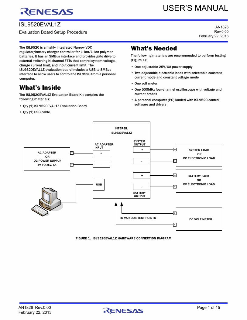
The ISL9520 is a highly integrated Narrow VDC regulator/battery charger controller for Li-ion/Li-ion polymer batteries. It has an SMBus interface and provides gate drive to external switching N-channel FETs that control system voltage, charge current limit, and input current limit. The ISL9520EVAL1Z evaluation board includes a USB to SMBus interface to allow users to control the ISL9520 from a personal computer.
What’s InsideThe ISL9520EVAL1Z Evaluation Board Kit contains the following materials:
• Qty (1) ISL9520EVAL1Z Evaluation Board
• Qty (1) USB cable
What’s NeededThe following materials are recommended to perform testing (Figure 1):
• One adjustable 25V/6A power supply
• Two adjustable electronic loads with selectable constant current mode and constant voltage mode
• One volt meter
• One 500MHz four-channel oscilloscope with voltage and current probes
• A personal computer (PC) loaded with ISL9520 control software and drivers
USB
INTERSILISL88731 EVAL2Z REVB
BATTERY OUTPUT
SYSTEM OUTPUTAC ADAPTER
INPUT
TO VARIOUS TEST POINTS
+
-DC VOLTMETER<10mV to >20v
+
- BATTERY PACKOR
ELECTRONIC LOAD
+
- SYSTEM LOADOR
ELECTRONIC LOAD
+
-
AC ADAPTEROR
DC POWER SUPPLY5V – 20V, 5A
FIGURE 1. ISL9520EVAL1Z HARDWARE CONNECTION DIAGRAM
DC POWER SUPPLY
AC ADAPTER
OR
4V TO 25V, 6A
CC ELECTRONIC LOAD
SYSTEM LOAD
OR
CV ELECTRONIC LOAD
BATTERY PACK
OR
DC VOLT METERTO VARIOUS TEST POINTS
AC ADAPTERINPUT
SYSTEM OUTPUT
BATTERY OUTPUT
USB
+
-
+
-
+
-
ISL9520EVAL1Z
INTERSIL
+
-
+
-
+
-
+
-
AN1826 Rev.0.00 Page 1 of 15February 22, 2013

ISL9520EVAL1Z
Install the SoftwareDownload and install the ISL9520 control software by following the instructions provided in the “ISL9520 Software Installation Guide”. This document also contains troubleshooting instructions to be used in the rare event that the software does not install on the first attempt.
Run the ISL9520 ApplicationPlug the USB cable up, one end to the computer and the other end to the evaluation board. No other connections are required to read and write to the registers.
The ISL9520 evaluation software should be available in your computer’s Start All Programs list. The “Intersil” folder will contain the program. Click the program name ISL9520 Control C1 to run the application.
Figure 2 shows the DAC Controls tab of the ISL9520 user interface. Initially, the software will indicate “FFFF” for the register values. Click the Read All icon to read the actual initial values in the registers.
Charge Current, Input Current, Max System Voltage, and Min System Voltage can be edited by clicking on the up/down arrows or by placing the cursor at the desired location and typing the correction. If the sense resistor shunts RS1 or RS2 have been changed on the board then the sense resistor values in the blue boxes should also be changed accordingly so that correct binary values are sent. The eggshell colored boxes are the digital values sent and read.
The white WRITE ALL 1/min box should be checked if a continuous test is desired, otherwise the SMBus Inactivity Time-out timer will shut down charging after 3 minutes.
FIGURE 2. ISL9520 DAC CONTROLS TAB
AN1826 Rev.0.00 Page 2 of 15February 22, 2013

ISL9520EVAL1Z
Figure 3 shows (ISL9520 Control Register tab) the control register 3D described in the data sheet and the bits that may be toggled by clicking on the individual bit switches. The configuration will be written when the Write CONTROL REG icon is clicked. The configuration is read when the READ ALL icon is clicked.
The Test Register should be written with “0600” to optimize the mode boundary transitions. To do this, place the cursor to the right of the first zero in the blue box, type a “6”, then hit the delete key once. Click on the Write test register icon, then click on the Read TEST REG icon to verify that the register has been updated.
FIGURE 3. ISL9520 CONTROL REGISTER TAB
AN1826 Rev.0.00 Page 3 of 15February 22, 2013

ISL9520EVAL1Z
Figure 4 shows the updated Control Register tab. The VendorID (reg FE) and DeviceID (reg FF) should display 0049 and 0005 respectively.
If the power connections have not already been made, they can be made at this time. Figure 1 shows the required power connections.
FIGURE 4. ISL9520 CONTROL REGISTER TAB AFTER EDITING TEST REGISTER
AN1826 Rev.0.00 Page 4 of 15February 22, 2013

AN
18
26R
ev.0
.00
Pag
e 5 of 15
Feb
rua
ry 22, 20
13
ISL9
520
EV
AL1
Z
0.1UF
HAT1127H
10UF
47UF
47UF
47UF
47UF
47UF
10UF
10UF
10UF
10UF
10UF
10UF
10UF
47UF
1000
PF
1UF
C28
C30
C32
C33
C35
C37
321 5
1
2
J6
J8
J3
J5
Q_BGATE
TP_BGATE
TP_GND_3
J9
TP_VBAT
TP_GND_2
TP_V_SYSTEM
4
543
21
21
21
21
21
21
C13
C15
C6
C38
C40
C25
C27
C29
C31
ISL9520EVAL1Z Schematics
FIGURE 5. ISL9520EVAL1Z REV A SCHEMATIC
SEE PAGE 2
10K
10K
BZX84C5V6LT1BSS84TA
BSS84TA
33
4.7UH
10K
1UF
0.010
2.2
0.1UF
HAT1127H
0.1UF
100K
1000PF 56K
10K10K
BZX84C5V6LT1
0
1UF
3K
0.1UF
0.22UF
10K
0.01UF
0.020
27K
470
1K
0.1UF
0
10K
0.047UF 47UF
HAT2116H
10K
47UF
10K
47UF
10UF
10UF
0
1UF
1UF
47UF
47UF
100
47UF
0.1UF
1010
0
0
0SCL
SDA
OPEN
HAT1127H
100K
0.1UF
VSMB
0
470PF
4.7
0.1UF
1UF
0.1UF
HAT2116H
HAT2116H
ISL9520HRTZ
HAT2116H
321
4
5
321
4
5
C14
C17
C20
C19
C18
C26
29
21
20
19
18
17
16
157
6
5
4
3
2
1
1
1
23
21
4
4
4
4
21
1
2
1
2
J1
J2
TP_SGATE
U1
TP_BMON
Q_AGATEQ_SGATE
TP_ACOK
R25
R24
TP_SMB_RST_N
TP_AMON
TP_VCOMP
TP_VFRQ
TP_ICOMP
TP_ACIN
C3 R26
R11
R12
R18
R15
R22
C2 R2
R3
R38
C1 R1
TP_GNDA_2
TP_GNDA_1
TP_VDDP
R17
Q70
TP_VDD
CF21
Q71
TP_DCIN
TP_AGATE
TP_GND_1
R44 Q44
TP_VADAPTER
CF11
RS1
J_UG-PHASE
Q2
Q1
TP_RS1_P TP_RS1_N
J_UGATE
C8
Q4
Q3
L1
R72
R70
TP_RS2_P
R27
J_SYSTEM
J_PHASE
RS2
TP_RS2_N
A
A
A A
1 2
EP
AGATE
ADET
CELL
VCOMP BMON
BGATE
CSON
CSOP
VDD
VDDP
LGATE
VFSW
ICOMP
DCIN
A
A
A
A
A
A
A
A
AA
AA
28 27 26 25 24 23 22141312111098
23
1
23
23
1
23
1
3215
3215
21
21
3215
3215
21
21
21
21
543
543
21
21
C5
C39
R7
R6
C24
C11
C10
R71 Z7
0 RF2
1
RF2
2
C12
C4
R61
R21
C7
R13
R9
CF1
2
RF1
1
RF1
2
CF1
3C
21
J_LG
ATE
R28
C23
C22
C52
C9
C34
C36
12
12
VFB
AM
ON
SD
AS
CL
VS
MB
RS
T#A
CO
KP
GN
DP
HA
SE
BO
OT
UG
ATE
CS
IP
SG
ATE
CS
IN
Z71
NC A
C
NC A
C

AN
18
26R
ev.0
.00
Pag
e 6 of 15
Feb
rua
ry 22, 20
13
ISL9
520
EV
AL1
Z
FIGURE 6. ISL9520 EVAL1Z REV A SCHEMATIC
ISL9520EVAL1Z Schematics (Continued)

ISL9520EVAL1Z
TABLE 1. ISL9520EVAL1Z, REV A EVALUATION BOARD BILL OF MATERIALS
NO.REFERENCE DESIGNATOR QTY DESCRIPTION MANUFACTURER
1 C1 1 CAP, SMD, 0603, 470pF, 50V, 5%, X7R, ROHS GENERIC
2 C2, C5, C6, C39 4 CAP, SMD, 0603, 1000pF, 50V, 5%, X7R, ROHS GENERIC
3 C3 1 CAP, SMD, 0402, 0.068µF, 25V, 10%, X7R, ROHS GENERIC
4 C10, C11, CF21, C304, C308 5 CAP, SMD, 0603, 1.0µF, 16V, 20%, X7R, ROHS GENERIC
5 C13, C22, C52 3 CAP, SMD, 0805, 1.0µF, 25V, 10%, X5R, ROHS GENERIC
6 C14, C17 2 CAP, SMD, 25TQC33MY, 33µF, 25V, 20%, ROHS SANYO
7 C18, C19, C20, C26, C28, C30, C32, C33, C35, C37
10 CAP, SMD, 20TQC47MY, 47µF, 20V, 20%, ROHS SANYO
8 C15 1 CAP, SMD, 1206, 10µF, 25V, 20%, X5R, ROHS GENERIC
9 C4, C7, C12, C24, C39, CF12, CF13, C305, C307, C309
9 CAP, SMD, 0603, 0.1µF, 25V, 10%, X7R, ROHS GENERIC
10 C9, C25, C27, C29, C31, C34, C36, C38, C40
9 CAP, SMD, 1812, 10µF, 25V, 20%, ROHS
11 CF11 1 CAP, SMD, 0603, 0.047µF, 25V, 10%, X7R, ROHS GENERIC
12 C8 1 CAP, SMD, 0603, 0.22µF, 25V, 20%, X7R, ROHS GENERIC
13 F325 1 FUSE, SMD, MICROSMD050F RAYCHEM-TYCO
14 J1, J6, J8 3 JACK, BANANA, BLACK, 164-6218 MOUSER
15 J2, J3, J5 3 JACK, BANANA, RED, 164-6219 MOUSER
16 JUSB 1 CONNECTOR, USB, MINI TYPE B MIL-MAX
17 J9, J_PHASE, J_SYSTEM 3 TEST POINT, SCOPE PROBE, 131-5031-00 TEKTRONIX
18 L1 1 INDUCTOR, SMD, 4.7µH, 24A, IHLP5050CE-ER-4R7-M-01 VISHAY/DALE
19 Q_AGATE, Q_BGATE, Q_SGATE 3 MOSFET, P-CHANNEL, SMD, LFPAK, 30V, 40A, HAT1127H RENESAS
20 Q44 1 MOSFET, P-CHANNEL, SMD, SOT23, BSS84TA FAIRCHILD
21 R1 1 RES, SMD, 0603, 3.01kΩ, 1/10W, 1%, TF, ROHS GENERIC
22 R2 1 RES, SMD, 0603, 56.2kΩ, 1/10W, 1%, TF, ROHS GENERIC
23 R3, R24, R25, RF22, R38, R302, R303, R307, R309, R312, R399
11 RES, SMD, 0603, 0Ω, 1/10W, TF, ROHS GENERIC
24 RF11, RF12 2 RES, SMD, 0603, 10, 1/10W, 5%, TF, ROHS GENERIC
25 R17 1 RES, SMD, 0603, 4.7Ω, 1/10W, 5%, TF, ROHS GENERIC
26 R26 RES, SMD, 0603, 499Ω, 1/10W, 1%, TF, ROHS
27 RF21 1 RES, SMD, 0603, 2.2Ω, 1/10W, 5%, TF, ROHS GENERIC
28 R27 1 RES, SMD, 2010, 0Ω, 1/2W, 5%, TF, ROHS GENERIC
29 R7, R9, R21 3 RES, SMD, 0603, 100kΩ, 1/10W, 1%, TF, ROHS GENERIC
30 R15, R304, R305 3 RES, SMD, 0603, 1kΩ, 1/10W, 1%, TF, ROHS GENERIC
31 R310, R311 2 RES, SMD, 0603, 1.8kΩ, 1/10W, 5%, TF, ROHS GENERIC
32 R11, R12, R13, R61 4 RES, SMD, 0603, 10.0kΩ, 1/10W, 1%, TF, ROHS GENERIC
33 R44 1 RES, SMD, 0603, 33.2Ω, 1/10W, 1%, TF, ROHS GENERIC
34 R6 1 RES, SMD, 0603, 402kΩ, 1/10W, 1%, TF, ROHS GENERIC
35 RS1 1 RES, SMD, 2010, 0.02Ω, 1W, 1%, LRC-LRF2010-01-R020-F IRC
36 RS2 1 RES, SMD, 2010, 0.01Ω, 1W, 1%, LRC-LRF2010-01-R010-F IRC
AN1826 Rev.0.00 Page 7 of 15February 22, 2013

ISL9520EVAL1Z
37 TP_ACIN, TP_ACOK, TP_AMON, TP_VFRQ, TP_ICOMP, TP_VCOMP,
TP_SMB_RST_N
7 TEST POINT, 0.063”, COMPACT YELLOW, CTP5009 KEYSTONE
38 TP_DCIN, TP_AGATE, TP_BGATE, TP_GND_1, TP_GND2, TP_GND_3, TP_RS1_N, TP_RS2_N, TP_SGATE,
TP_GNDA_1, TP_GNDA_2
11 TEST POINT, 0.063”, COMPACT BLACK, CTP5006 KEYSTONE
39 TP_VDD, TP_VBAT, TP_VDDP, TP_VADAPTER, TP_V_SYSTEM
5 TEST POINT, 0.063”, COMPACT RED, CTP5005 KEYSTONE
40 TP304, TP305, TP306, TP_SCL, TP_SDA, TP_VHST, TP_GND_D,
TP_RS1_P, TP_RS2_P
9 TEST POINT, 0.063”, COMPACT WHITE, CTP5007 KEYSTONE
41 U1 1 IC, BATTERY CHARGER, ISL9520, QFN50_5X7B_EP INTERSIL
42 U301 1 IC, MICROCONTROLLER, C8051F320, 32LQFP_80 SILICON LABS
TABLE 1. ISL9520EVAL1Z, REV A EVALUATION BOARD BILL OF MATERIALS (Continued)
NO.REFERENCE DESIGNATOR QTY DESCRIPTION MANUFACTURER
AN1826 Rev.0.00 Page 8 of 15February 22, 2013

ISL9520EVAL1Z
FIGURE 7. TOP SILKSCREEN
AN1826 Rev.0.00 Page 9 of 15February 22, 2013

ISL9520EVAL1Z
FIGURE 8. BOTTOM SILKSCREEN
AN1826 Rev.0.00 Page 10 of 15February 22, 2013

ISL9520EVAL1Z
FIGURE 9. TOP LAYER COPPER
AN1826 Rev.0.00 Page 11 of 15February 22, 2013

ISL9520EVAL1Z
FIGURE 10. LAYER 2 COPPER
AN1826 Rev.0.00 Page 12 of 15February 22, 2013

ISL9520EVAL1Z
FIGURE 11. LAYER 3 COPPER
AN1826 Rev.0.00 Page 13 of 15February 22, 2013

ISL9520EVAL1Z
FIGURE 12. BOTTOM LAYER COPPER
AN1826 Rev.0.00 Page 14 of 15February 22, 2013

http://www.renesas.comRefer to "http://www.renesas.com/" for the latest and detailed information.
Renesas Electronics America Inc.1001 Murphy Ranch Road, Milpitas, CA 95035, U.S.A.Tel: +1-408-432-8888, Fax: +1-408-434-5351Renesas Electronics Canada Limited9251 Yonge Street, Suite 8309 Richmond Hill, Ontario Canada L4C 9T3Tel: +1-905-237-2004Renesas Electronics Europe LimitedDukes Meadow, Millboard Road, Bourne End, Buckinghamshire, SL8 5FH, U.KTel: +44-1628-651-700, Fax: +44-1628-651-804Renesas Electronics Europe GmbHArcadiastrasse 10, 40472 Düsseldorf, Germany Tel: +49-211-6503-0, Fax: +49-211-6503-1327Renesas Electronics (China) Co., Ltd.Room 1709 Quantum Plaza, No.27 ZhichunLu, Haidian District, Beijing, 100191 P. R. ChinaTel: +86-10-8235-1155, Fax: +86-10-8235-7679Renesas Electronics (Shanghai) Co., Ltd.Unit 301, Tower A, Central Towers, 555 Langao Road, Putuo District, Shanghai, 200333 P. R. China Tel: +86-21-2226-0888, Fax: +86-21-2226-0999Renesas Electronics Hong Kong LimitedUnit 1601-1611, 16/F., Tower 2, Grand Century Place, 193 Prince Edward Road West, Mongkok, Kowloon, Hong KongTel: +852-2265-6688, Fax: +852 2886-9022Renesas Electronics Taiwan Co., Ltd.13F, No. 363, Fu Shing North Road, Taipei 10543, TaiwanTel: +886-2-8175-9600, Fax: +886 2-8175-9670Renesas Electronics Singapore Pte. Ltd.80 Bendemeer Road, Unit #06-02 Hyflux Innovation Centre, Singapore 339949Tel: +65-6213-0200, Fax: +65-6213-0300Renesas Electronics Malaysia Sdn.Bhd.Unit 1207, Block B, Menara Amcorp, Amcorp Trade Centre, No. 18, Jln Persiaran Barat, 46050 Petaling Jaya, Selangor Darul Ehsan, MalaysiaTel: +60-3-7955-9390, Fax: +60-3-7955-9510Renesas Electronics India Pvt. Ltd.No.777C, 100 Feet Road, HAL 2nd Stage, Indiranagar, Bangalore 560 038, IndiaTel: +91-80-67208700, Fax: +91-80-67208777Renesas Electronics Korea Co., Ltd.17F, KAMCO Yangjae Tower, 262, Gangnam-daero, Gangnam-gu, Seoul, 06265 KoreaTel: +82-2-558-3737, Fax: +82-2-558-5338
SALES OFFICES
© 2018 Renesas Electronics Corporation. All rights reserved.Colophon 7.0
(Rev.4.0-1 November 2017)
Notice
1. Descriptions of circuits, software and other related information in this document are provided only to illustrate the operation of semiconductor products and application examples. You are fully responsible for
the incorporation or any other use of the circuits, software, and information in the design of your product or system. Renesas Electronics disclaims any and all liability for any losses and damages incurred by
you or third parties arising from the use of these circuits, software, or information.
2. Renesas Electronics hereby expressly disclaims any warranties against and liability for infringement or any other claims involving patents, copyrights, or other intellectual property rights of third parties, by or
arising from the use of Renesas Electronics products or technical information described in this document, including but not limited to, the product data, drawings, charts, programs, algorithms, and application
examples.
3. No license, express, implied or otherwise, is granted hereby under any patents, copyrights or other intellectual property rights of Renesas Electronics or others.
4. You shall not alter, modify, copy, or reverse engineer any Renesas Electronics product, whether in whole or in part. Renesas Electronics disclaims any and all liability for any losses or damages incurred by
you or third parties arising from such alteration, modification, copying or reverse engineering.
5. Renesas Electronics products are classified according to the following two quality grades: “Standard” and “High Quality”. The intended applications for each Renesas Electronics product depends on the
product’s quality grade, as indicated below.
"Standard": Computers; office equipment; communications equipment; test and measurement equipment; audio and visual equipment; home electronic appliances; machine tools; personal electronic
equipment; industrial robots; etc.
"High Quality": Transportation equipment (automobiles, trains, ships, etc.); traffic control (traffic lights); large-scale communication equipment; key financial terminal systems; safety control equipment; etc.
Unless expressly designated as a high reliability product or a product for harsh environments in a Renesas Electronics data sheet or other Renesas Electronics document, Renesas Electronics products are
not intended or authorized for use in products or systems that may pose a direct threat to human life or bodily injury (artificial life support devices or systems; surgical implantations; etc.), or may cause
serious property damage (space system; undersea repeaters; nuclear power control systems; aircraft control systems; key plant systems; military equipment; etc.). Renesas Electronics disclaims any and all
liability for any damages or losses incurred by you or any third parties arising from the use of any Renesas Electronics product that is inconsistent with any Renesas Electronics data sheet, user’s manual or
other Renesas Electronics document.
6. When using Renesas Electronics products, refer to the latest product information (data sheets, user’s manuals, application notes, “General Notes for Handling and Using Semiconductor Devices” in the
reliability handbook, etc.), and ensure that usage conditions are within the ranges specified by Renesas Electronics with respect to maximum ratings, operating power supply voltage range, heat dissipation
characteristics, installation, etc. Renesas Electronics disclaims any and all liability for any malfunctions, failure or accident arising out of the use of Renesas Electronics products outside of such specified
ranges.
7. Although Renesas Electronics endeavors to improve the quality and reliability of Renesas Electronics products, semiconductor products have specific characteristics, such as the occurrence of failure at a
certain rate and malfunctions under certain use conditions. Unless designated as a high reliability product or a product for harsh environments in a Renesas Electronics data sheet or other Renesas
Electronics document, Renesas Electronics products are not subject to radiation resistance design. You are responsible for implementing safety measures to guard against the possibility of bodily injury, injury
or damage caused by fire, and/or danger to the public in the event of a failure or malfunction of Renesas Electronics products, such as safety design for hardware and software, including but not limited to
redundancy, fire control and malfunction prevention, appropriate treatment for aging degradation or any other appropriate measures. Because the evaluation of microcomputer software alone is very difficult
and impractical, you are responsible for evaluating the safety of the final products or systems manufactured by you.
8. Please contact a Renesas Electronics sales office for details as to environmental matters such as the environmental compatibility of each Renesas Electronics product. You are responsible for carefully and
sufficiently investigating applicable laws and regulations that regulate the inclusion or use of controlled substances, including without limitation, the EU RoHS Directive, and using Renesas Electronics
products in compliance with all these applicable laws and regulations. Renesas Electronics disclaims any and all liability for damages or losses occurring as a result of your noncompliance with applicable
laws and regulations.
9. Renesas Electronics products and technologies shall not be used for or incorporated into any products or systems whose manufacture, use, or sale is prohibited under any applicable domestic or foreign laws
or regulations. You shall comply with any applicable export control laws and regulations promulgated and administered by the governments of any countries asserting jurisdiction over the parties or
transactions.
10. It is the responsibility of the buyer or distributor of Renesas Electronics products, or any other party who distributes, disposes of, or otherwise sells or transfers the product to a third party, to notify such third
party in advance of the contents and conditions set forth in this document.
11. This document shall not be reprinted, reproduced or duplicated in any form, in whole or in part, without prior written consent of Renesas Electronics.
12. Please contact a Renesas Electronics sales office if you have any questions regarding the information contained in this document or Renesas Electronics products.
(Note 1) “Renesas Electronics” as used in this document means Renesas Electronics Corporation and also includes its directly or indirectly controlled subsidiaries.
(Note 2) “Renesas Electronics product(s)” means any product developed or manufactured by or for Renesas Electronics.