isg 1000 user’s guide -...
TRANSCRIPT

ISG 1000User’s Guide
Release 5.0.0
Juniper Networks, Inc.
1194 North Mathilda Avenue
Sunnyvale, CA 94089
USA
408-745-2000
www.juniper.net
Part Number: 093-1511-000, Revision A

ii
Copyright Notice
Copyright © 2005 Juniper Networks, Inc. All rights reserved.
Juniper Networks, the Juniper Networks logo, NetScreen, NetScreen Technologies, the NetScreen logo, NetScreen-Global Pro, ScreenOS, and GigaScreen are registered trademarks of Juniper Networks, Inc. in the United States and other countries.
The following are trademarks of Juniper Networks, Inc.: Deep Inspection, ERX, ESP, Instant Virtual Extranet, Internet Processor, J-Protect, JUNOS, JUNOScope, JUNOScript, JUNOSe, M5, M7i, M10, M10i, M20, M40, M40e, M160, M320, M-series, MMD, NetScreen-5GT, NetScreen-5XP, NetScreen-5XT, NetScreen-25, NetScreen-50, NetScreen-100, NetScreen-204, NetScreen-208, NetScreen-500, NetScreen-5200, NetScreen-5400, NetScreen-IDP 10, NetScreen-IDP 100, NetScreen-IDP 500, NetScreen-IDP 1000, IDP 50, IDP 200, IDP 600, IDP 1100, ISG 1000, ISG 2000, NetScreen-Global Pro Express, NetScreen-Remote Security Client, NetScreen-Remote VPN Client, NetScreen-SA 1000 Series, NetScreen-SA 3000 Series, NetScreen-SA 5000 Series, NetScreen-SA Central Manager, NetScreen Secure Access, NetScreen-SM 3000, NetScreen-Security Manager, GigaScreen ASIC, GigaScreen-II ASIC, NMC-RX, SDX, Stateful Signature, T320, T640, and T-series.
Information in this document is subject to change without notice.
No part of this document may be reproduced or transmitted in any form or by any means, electronic or mechanical, for any purpose, without receiving written permission from:
Juniper Networks, Inc.ATTN: General Counsel1194 N. Mathilda Ave.Sunnyvale, CA 94089
FCC Statement
The following information is for FCC compliance of Class A devices: This equipment has been tested and found to comply with the limits for a Class A digital device, pursuant to part 15 of the FCC rules. These limits are designed to provide reasonable protection against harmful interference when the equipment is operated in a commercial environment. The equipment generates, uses, and can radiate radio-frequency energy and, if not installed and used in accordance with the instruction manual, may cause harmful interference to radio communications. Operation of this equipment in a residential area is likely to cause harmful interference, in which case users will be required to correct the interference at their own expense.
The following information is for FCC compliance of Class B devices: The equipment described in this manual generates and may radiate radio-frequency energy. If it is not installed in accordance with NetScreen’s installation instructions, it may cause interference with radio and television reception. This equipment has been tested and found to comply with the limits for a Class B digital device in accordance with the specifications in part 15 of the FCC rules. These specifications are designed to provide reasonable protection against such interference in a residential installation. However, there is no guarantee that interference will not occur in a particular installation.
If this equipment does cause harmful interference to radio or television reception, which can be determined by turning the equipment off and on, the user is encouraged to try to correct the interference by one or more of the following measures:
Reorient or relocate the receiving antenna.
Increase the separation between the equipment and receiver.
Consult the dealer or an experienced radio/TV technician for help.
Connect the equipment to an outlet on a circuit different from that to which the receiver is connected.
Caution: Changes or modifications to this product could void the user's warranty and authority to operate this device.
Disclaimer
THE SOFTWARE LICENSE AND LIMITED WARRANTY FOR THE ACCOMPANYING PRODUCT ARE SET FORTH IN THE INFORMATION PACKET THAT SHIPPED WITH THE PRODUCT AND ARE INCORPORATED HEREIN BY THIS REFERENCE. IF YOU ARE UNABLE TO LOCATE THE SOFTWARE LICENSE OR LIMITED WARRANTY, CONTACT YOUR JUNIPER NETWORKS REPRESENTATIVE FOR A COPY.

Table of Contents
Audience.......................................................................................................... vOrganization .................................................................................................... vCommand Line Interface (CLI) Conventions.................................................... viObtaining Documentation and Customer Support........................................... vi
Chapter 1 Overview 1
Front Panel ......................................................................................................1LED Dashboard .........................................................................................2Interface Modules ......................................................................................3
Ports and Port LEDs ............................................................................310/100 Mbps Interface Module............................................................410/100/1000 Mbps Interface Module...................................................4Mini-GBIC Interface Connector Module ...............................................4
Compact Flash...........................................................................................4Management Interfaces .............................................................................5High Availability Interfaces ........................................................................5Fan Tray ....................................................................................................5
Rear Panel .......................................................................................................6AC Power Supply Unit ...............................................................................6DC Power Supply Unit ...............................................................................6..................................................................................................................6
Chapter 2 Installing the Device 7
Before You Begin .............................................................................................7Equipment Rack Installation ............................................................................8
Front-Mount ..............................................................................................8Mid-Mount .................................................................................................8
Chapter 3 Configuring the Device 11
Operational Modes.........................................................................................12Route.......................................................................................................12Transparent .............................................................................................12
Cabling the ISG 1000 Device ..........................................................................13Connecting to the ISG 1000 Device................................................................14
Starting a CLI Session ..............................................................................14Establishing a Console Session..........................................................14Starting a CLI Session with Telnet .....................................................15Starting a CLI Session Using Dialup ...................................................16
Establishing a WebUI Management Session.............................................16Changing Your Admin Name and Password ............................................17Setting the IP Address of the Management Interface ...............................17
Table of Contents iii

iv
ISG 1000 User’s Guide
Configuring Interfaces....................................................................................18Viewing Interface Settings .......................................................................19Setting the IP Address for the Trust Zone Interface..................................19Setting the IP Address for the Untrust Zone Interface ..............................20Setting Traffic Policies .............................................................................20
Configuring High Availability..........................................................................21Configuring the Chassis Alarm .......................................................................21Uploading and Downloading Files ..................................................................22Resetting the Device ......................................................................................22
Chapter 4 Servicing the Device 23
Removing and Inserting Interface Modules ....................................................24Removing Interface Modules ...................................................................24Inserting Interface Modules .....................................................................25
Replacing a DC Power Supply ........................................................................26Replacing an AC Power Supply ......................................................................26Replacing the Fan Tray ..................................................................................27Replacing the Fan Tray Filter .........................................................................27Installing Gigabit Ethernet Cables...................................................................29Removing Gigabit Ethernet Cables .................................................................29Installing a Mini-GBIC Transceiver..................................................................29Removing a Mini-GBIC Transceiver ................................................................30
Appendix A Specifications A-I
ISG 1000 Device Attributes ...........................................................................A-IElectrical Specification ..................................................................................A-IEnvironmental ............................................................................................ A-IICertifications ............................................................................................... A-IIConnectors .................................................................................................. A-II
Index..........................................................................................................................IX-I
Table of Contents

About This Guide
The purpose-built Juniper Networks Integrated Security Gateway (ISG) 1000 system integrates firewall, deep inspection, VPN, and traffic management functionality in a low-profile, modular chassis. The ISG 1000 system is ideal for medium-sized central enterprise sites, large regional sites, and security data centers or server farms.
Built around a fourth-generation security ASIC, the GigaScreen3, the ISG 1000 system provides for flexible configuration with the following interface options for its two open slots:
10/100 Mbps interface module, for 10/100 Base-T connections (4 and 8 ports)
10/100/1000 Mbps interface module (2 ports)
Mini-GBIC interface module, for fiber-optic connections (2 ports)
The chassis also has four built-in 10/100/1000 ports for a maximum of 20 configurable ports per system.
This guide describes how to install, configure, and service the ISG 1000 device. It also lists device requirements and performance specifications.
Audience
This guide is intended for experienced network specialists working to provide security and routing across networks within an Internet access environment.
Organization
This manual contains four chapters and one appendix.
Chapter 1, "Overview" provides an overview of the system and its components.
Chapter 2, "Installing the Device" provides instructions for installing the system in an equipment rack.
Chapter 3, "Configuring the Device" explains how to cable the system and configure an interface.
Chapter 4, "Servicing the Device" explains how to replace the modules, fan tray and filter, and power supply unit.
Appendix A, "Specifications" lists the attributes of the ISG 1000 system.
Audience v

ISG 1000 User’s Guide
vi
Command Line Interface (CLI) Conventions
The following conventions are used when presenting the syntax of a command line interface (CLI) command:
Anything inside square brackets [ ] is optional.
Anything inside braces { } is required.
If there is more than one choice, each choice is separated by a pipe ( | ). For example,
set interface { ethernet1 | ethernet2 | ethernet3 } manage
means “set the management options for the ethernet1, ethernet2, or ethernet3 interface.”
Variables appear in italic. For example:
set admin user name1 password xyz When a CLI command appears within the context of a sentence, it is in bold (except for variables, which are always in italic). For example:
Use the get system command to display the serial number of a NetScreen device.
Obtaining Documentation and Customer Support
To obtain technical documentation for any Juniper Networks NetScreen product, visit www.juniper.net/techpubs/.
For technical support, open a support case using the Case Manager link at http://www.juniper.net/support/ or call 1-888-314-JTAC (within the United States) or 1-408-745-9500 (outside the United States).
If you find any errors or omissions in the following content, please contact us at the e-mail address below:
NOTE: When typing a keyword, you only have to type enough letters to identify the word uniquely. For example, typing set adm u joe j12fmt54 is enough to enter the command set admin user joe j12fmt54 . Although you can use this shortcut when entering commands, all the commands documented here are presented in their entirety.
Command Line Interface (CLI) Conventions

Chapter 1
Overview
This chapter provides detailed descriptions of the ISG 1000 chassis and modular components. It includes the following topics:
“Front Panel” on page 1
“LED Dashboard” on page 2
“Interface Modules” on page 3
“Compact Flash” on page 4
“Management Interfaces” on page 5
“High Availability Interfaces” on page 5
“Fan Tray” on page 5
“Rear Panel” on page 6
“AC Power Supply Unit” on page 6
“DC Power Supply Unit” on page 6
Front Panel
The front panel of the ISG 1000 device has the following components:
LED dashboard
Management, console, and modem ports
Four built-in 10/100/1000 Mbps ports
Two removable, replaceable interface modules
One compact flash card slot
One fan tray and filter
Front Panel 1

ISG 1000 User’s Guide
2
LED DashboardThe LED dashboard shows information about critical device functions. See the LED table that follows this section for the name, function, and meaning of the color for each LED.
When the system powers up, the STATUS LED changes from off to blinking green. Startup takes approximately 90 seconds to complete. If you want to turn the system off and on again, we recommend waiting a few seconds between shutting it down and powering it back up.
HA
FLASH
PWR
FAN
ALARM
MOD1
TEMP
MOD2
STATUS
HA
FLASH
PWR
FAN
ALARM
MOD1
TEMP
MOD2
STATUS
LED Function Color Meaning
POWER Power Supply Green Power supply is functioning correctly.
Off System is not receiving power.
Red Power supply unit is not functioning correctly.
ALARM System Alarm Blinking red Continuous blinking indicates a self-test failure occurred wihile ScreenOS was starting up. Certain algorithm and ACL failures can cause this to happen.
The system alarm blinks once for each software attack.
Amber One of the following failures has occurred:
Power supply is turned off.
Hardware failure.
Error with software module.
Off No alarm condition(s) present.
TEMP Temperature Green Temperature is within 32° F (0° C)- 122° F (50° C).
Orange Temperature is within 132° F (56° C) - 150° F (66° C).
Red Temperature exceeds 150° F (66° C).
Front Panel

Chapter 1: Overview
Interface ModulesThe front panel of the ISG 1000 system has two interface module bays, which can accommodate the following types of modules:
10/100 Mbps interface module, for 10/100 Base-T connections (4 and 8 ports)
10/100/1000 Mbps interface module (2 ports)
Mini-GBIC interface module, for fiber-optic connections (2 ports)
The modules are not hot-swappable. Your network needs determine the kinds of interfaces needed to deploy ISG 1000 systems.
Ports and Port LEDsThe ISG 1000 system supports a maximum of 20 ports. Each port has a transmit/receive (TX/RX) activity LED and a link status LED:
For 10/100 Mbps ports, the TX/RX LED is located in the upper left corner of the port, and the link status LED is in the upper right corner.
For 10/100/1000 Mbps ports and gigabit Ethernet ports, the TX/RX LEDs are located to the left of the corresponding port.
STATUS System Status Blinking green System is active.
Green System is booting.
Off System is off.
HA High Availability Status Green Device is the primary device.
Amber Device is a backup device.
Red HA is defined; this device is not the backup.
Off No HA activity defined.
FAN Fan Status Green All fans functioning properly.
Red One or more fans failed or fan subsystem is not receiving power.
MOD1 Green Security module is installed.
Off No card installed.
MOD2 Green Security module is installed.
Off No card installed.
FLASH Compact Flash Status Green PC card is installed in compact flash slot.
Blinking green Read-write activity is detected.
Off Compact flash slot is empty.
LED Function Color Meaning
NOTE: You can use one 10/100/1000 and one GBIC card in the same ISG 1000 system.
Front Panel 3

ISG 1000 User’s Guide
4
The TX/RX activity LED is dark when not active and blinks green when active. The link status LED is dark when not linked and glows solid green when a link is established.
10/100 Mbps Interface ModuleThe 4-port or 8-port 10/100 Mbps interface module is appropriate for a 10/100 Base-T LAN. Connect the ports using a twisted pair cable with RJ-45 connectors.
10/100/1000 Mbps Interface ModuleThe 2-port 10/100/1000 Mbps interface module is appropriate for a 10/100/1000 Base-T LAN. Connect the ports using a twisted pair cable with RJ-45 connectors.
Mini-GBIC Interface Connector ModuleThe mini-GBIC interface module provides connectivity to fiber-based, gigabit Ethernet LANs. Connect the module using a single-mode or multimode optical cable.
Compact FlashThe compact flash slot is for downloading or uploading system software or configuration files and for saving log files to a hot-swappable compact flash card.
Front Panel

Chapter 1: Overview
Management InterfacesYou can manage a ISG 1000 system using one of three ports:
Console, an RJ-45 serial port for local administration. It connects to a terminal with an RJ-45-to-DB-9 (female to male) straight-through serial cable.
Modem, an RJ-45 serial port that connects to a modem to allow remote administration. It connects to a workstation with an RJ-45-to-DB-9 (female to male) serial cable with a null modem adapter. We do not recommend using the modem port for regular remote administration.
10/100 MGT, a port with a fixed 10/100 Base-T interface to provide a dedicated connection for management traffic. It has a separate IP address and netmask (default is 192.168.1.1/24) and is configurable with the command line interface (CLI) through Telnet or the WebUI. The MGT port is only to be used for management purposes and is not capable of routing traffic to other interfaces. We do not recommend passing session traffic through this interface.
High Availability InterfacesThe ISG 1000 system does not have dedicated High Availability (HA) interfaces; however, you can cable and configure two ports per system to behave as an HA interface once the system is running. In an HA configuration, one device is configured as the primary device and the other is configured as the backup. If the primary device fails, the backup device takes over as the primary. Any number and type of interface module port can be used as an HA port.
For information on cabling HA, see “Configuring High Availability” on page 21.
Fan TrayThe ISG 1000 device has a single hot-swappable three-fan tray, which you can access on the left front side of the chassis.
NOTE: We recommend 10/100/1000 Mbps interface or mini-GBIC interface modules for HA ports. You cannot mix mini-GBIC and 10/100/1000 Mbps ports as HA ports.
WARNING: If a fan stops operating as a result of failure or removal, the system continues to run. Do not leave the fan tray empty for more than two minutes; otherwise, heat failure or permanent damage can occur.
Front Panel 5

ISG 1000 User’s Guide
6
Rear Panel
The rear panel of the ISG 1000 device contains a single factory-installed modular power supply unit (PSU). The PSU is available for AC or DC use and weighs 1.5 pounds (.45 kilograms). The PSU attaches with thumbscrews to allow field replacement. The POWER LED on the front panel of the ISG 1000 device glows either green or red. Green indicates correct function, and red indicates PSU failure.
AC Power Supply UnitThe AC PSU faceplate contains a power switch and a male power outlet.
DC Power Supply UnitThe DC PSU faceplate contains a power switch, hex nut, and three DC power terminal blocks that connect to power cables.
Rear Panel

Chapter 2
Installing the Device
This chapter describes how to install an ISG 1000 device in a standard 19-inch equipment rack. Topics in this chapter include:
“Before You Begin” on page 7
“Equipment Rack Installation” on page 8
“Front-Mount” on page 8
“Mid-Mount” on page 8
Before You Begin
The location of the chassis, the layout of the equipment rack, and the security of your wiring room are crucial for proper system operation.
Observing the following precautions can prevent shutdowns, equipment failures, and injuries:
Before installation, always check that the power supply is disconnected from any power source.
Ensure that the room in which you operate the device has adequate air circulation and that the room temperature does not exceed 122° F (50° C).
Allow 3 feet (1 meter) of clear space to the front and back of the device.
NOTE: For safety warnings and instructions, please refer to the NetScreen Safety Guide. Before working on any equipment, you should be aware of the hazards involved with electrical circuitry and familiar with standard practices for preventing accidents.
WARNING: To prevent abuse and intrusion by unauthorized personnel, install the ISG 1000 system in a secure environment.
Before You Begin 7

ISG 1000 User’s Guide
8
Do not place the device in an equipment rack frame that blocks an intake or exhaust port. Ensure that enclosed racks have fans and louvered sides.
This device exceeds 36 pounds (16.3 kilograms). Take precautions when lifting and stablizing the device.
Correct these hazardous conditions before any installation: moist or wet floors, leaks, ungrounded or frayed power cables, or missing safety grounds.
Equipment Rack Installation
The ISG 1000 device fits into a standard 19-inch equipment rack and comes with two pre-installed mounting brackets and 4 screws for front-mount or mid-mount installation.
Front-MountTo front-mount the ISG 1000 device, you need a phillips-head screwdriver (not provided) and 4 screws (provided in the shipping box).
1. Slide the ISG 1000 device into the rack.
2. Support the chassis while you attach 2 screws to each mounting bracket and to the rack frame.
When correctly installed, the ISG 1000 device sits level in the equipment rack.
Mid-MountTo mid-mount the ISG 1000 device, you need a phillips-head screwdriver (not provided) and the 4 screws (provided in the shipping box). A total of 10 screws are required to complete this procedure.
1. Using a Phillips-head screwdriver, remove the pre-installed mounting brackets from the front-mount position. Save the 6 screws for steps 2 and 3.
2. Using 3 of the saved screws, attach the one mounting bracket to the middle of one side of the ISG 1000 device.
NOTE: Mounting brackets are pre-installed for front-mount installation. Desktop operation is not recommended.
Equipment Rack Installation
Chapter 2: Installing the Device
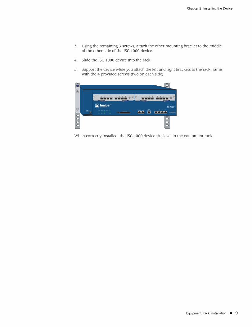
3. Using the remaining 3 screws, attach the other mounting bracket to the middle of the other side of the ISG 1000 device.
4. Slide the ISG 1000 device into the rack.
5. Support the device while you attach the left and right brackets to the rack frame with the 4 provided screws (two on each side).
When correctly installed, the ISG 1000 device sits level in the equipment rack.
Equipment Rack Installation 9

ISG 1000 User’s Guide
10
Equipment Rack Installation
Chapter 3
Configuring the Device
This chapter describes how to connect and configure an ISG 1000 device in your network. It includes the following topics:
“Operational Modes” on page 12
“Route” on page 12
“Transparent” on page 12
“Cabling the ISG 1000 Device” on page 13
“Connecting to the ISG 1000 Device” on page 14
“Starting a CLI Session” on page 14
“Establishing a WebUI Management Session” on page 16
“Changing Your Admin Name and Password” on page 17
“Configuring Interfaces” on page 18
“Viewing Interface Settings” on page 19
“Setting the IP Address of the Management Interface” on page 17
“Setting the IP Address for the Trust Zone Interface” on page 19
“Setting the IP Address for the Untrust Zone Interface” on page 20
“Setting Traffic Policies” on page 20
“Configuring High Availability” on page 21
“Configuring the Chassis Alarm” on page 21
“Uploading and Downloading Files” on page 22
“Resetting the Device” on page 22
11

ISG 1000 User’s Guide
12
Operational Modes
The ISG 1000 device supports two operational modes:
Route (default)
Transparent
The mode that you choose depends on how you intend to deploy the device.
RouteIn Route mode, the ISG 1000 operates at Layer 3 and offers static or dynamic routing solutions and security with Network Address Translation (NAT). After you configure each ISG 1000 interface with an IP address and subnet mask, you can configure individual interfaces to perform NAT so that untrusted networks (external) cannot learn about your network.
For more information about NAT, see the “Fundamentals” volume, and for more information about setting up static or dynamic routing, see the “Routing” volume, of the NetScreen Concepts & Examples ScreenOS Reference Guide.
TransparentIn Transparent mode, the ISG 1000 operates as a Layer-2 bridge. A NetScreen device operating in Transparent mode is invisible to the network and uses configured security policies to perform firewall, VPN, and traffic management.
To use Transparent mode, you need to bind each interface to a Layer-2 security zone and then assign each host in your local network a public IP address. Each IP address in your trusted (local) networks must be public, routable, and accessible from untrusted (external) networks. For more information about binding interfaces to zones and setting policies, see the “Fundamentals” volume in the NetScreen Concepts & Examples ScreenOS Reference Guide.
NOTE: Register your product at www.juniper.net/support/warranty/register.html to activate certain ScreenOS services, such as Deep Inspection Signature Service. After registering your product, use the WebUI or CLI to obtain the service subscription. For more information about registering your product and obtaining subscriptions for specific services, see the “Fundamentals” volume in the NetScreen Concepts & Examples ScreenOS Reference Guide.
NOTE: You must run the ISG 1000 in Route mode if you require Network Address Translation (NAT).
Operational Modes

Chapter 3: Configuring the Device
Cabling the ISG 1000 Device
The following illustration shows one possible cabling scenario for an ISG 1000 device in a network. The illustration shows one GBIC module (left bay) port connected to the external router (Untrust) and one FE8 interface module (right bay) port connected to the internal switch (Trust). One of the built-in 10/100/1000 ports connects to the DMZ.
To add an ISG 1000 device to your network:
1. Install the ISG 1000 device in an equipment rack but do not power up the device. See “Before You Begin” on page 7.
2. Make sure that the ISG 1000 power supply unit (PSU) switch is turned off.
3. Connect the power cable (included) to the ISG 1000 PSU and to a power source.
4. Connect an RJ-45 cross-over cable from the last 10/100 Ethernet port in the FE8 interface module (ethernet3/8) to the internal switch, router, or hub.
5. Connect an optical cable from the far left interface of the GBIC module (ethernet2/1) to the external router.
NOTE: This example is not the only possible configuration. This example requires default physical port and interface settings. If you have changed port or interface configurations, these instructions might not work correctly.
NOTE: Check your router, hub, switch, or computer documentation to see if these devices require any further configuration for your Trust and Untrust zones. Verify if it is necessary to switch off the power to any new device you add to the LAN.
Cabling the ISG 1000 Device 13

ISG 1000 User’s Guide
14
6. Connect an RJ-45 cross-over cable from the first built-in 10/100/1000 interface (ethernet1/1) to the DMZ switch, router, or hub.
7. Set the ON/OFF switch to the ON position.
After the ISG 1000 boots up, the POWER LED glows green, the STATUS LED blinks green, and the LINK LEDs for the cabled interfaces glow green. (For a list of Link Status LED meanings, see “Interface Modules” on page 3.)
Connecting to the ISG 1000 Device
You can manage the device from a command line interface (CLI) or with the WebUI, a web-based GUI management application.
This section contains the following procedures:
Establishing a terminal emulator connection
Changing your admin name and password
Changing the IP address of the Management Interface
Starting a CLI session
Establishing a WebUI management session
Starting a CLI SessionYou can use a console, Telnet, or dialup connection to configure and manage the device.
Establishing a Console SessionTo establish an initial console session:
1. Insert the female end of the supplied DB-9-to-RJ-45 adapter into the serial port of your computer or laptop.
2. Insert the RJ-45 connector of an ethernet cable into the console port of the ISG 1000 device.
NOTE: During your first CLI session, we recommend that you change the default admin name and password.
RJ-45 Connector
DB-9 Adapter
Connecting to the ISG 1000 Device

Chapter 3: Configuring the Device
3. Launch a command line interface (CLI) session between your computer and the ISG 1000 using a standard serial terminal emulation program, such as Hilgraeve HyperTerminal. The settings should be as follows:
Baud Rate to 9600
Parity to No
Data Bits to 8
Stop Bit to 1
Flow Control to none
4. Press the Enter key to see the Login prompt.
5. At the Login prompt, enter netscreen.
6. At the Password prompt, enter netscreen.
7. (Optional) By default, the console times out and terminates automatically after 10 minutes of idle time. To remove the timeout interval, enter:
set console timeout 0
Starting a CLI Session with TelnetTo establish a Telnet session with the ISG 1000 device:
1. Connect an RJ-45 cable from the MGT interface to the internal switch, router, or hub in your LAN (see “Setting the IP Address for the Trust Zone Interface” on page 19).
2. Open a Telnet session, specifying the current MGT interface IP address. For example, in Windows, click Start > Run , enter telnet followed by the IP address of the MGT interface, and click OK.
For example, if the MGT interface has an IP address of 10.100.2.183, enter:
telnet 10.100.2.183 3. At the Login prompt, enter your admin name (default is netscreen).
4. At the Password prompt, enter your password (default is netscreen).
5. (Optional) By default, the console times out and terminates automatically after 10 minutes of idle time. To remove the timeout interval, enter:
set console timeout 0
NOTE: Both login and password are case-sensitive.
NOTE: Both admin name and password are case-sensitive.
Connecting to the ISG 1000 Device 15

ISG 1000 User’s Guide
16
Starting a CLI Session Using DialupEach ISG 1000 provides a modem port that allows you to establish a remote CLI session using a dialup connection through a 9600 bps modem. Dialing into the modem establishes a dialup CLI connection. You must use an RJ-45-to-DB-9 (female to male) serial cable with a null modem adapter.
Establishing a WebUI Management SessionTo access the ISG 1000 device through the WebUI management application:
1. Connect your computer (or your LAN hub) to the MGT interface using a CAT5 Ethernet cable.
2. Launch a web browser, enter the IP address of the MGT interface in the URL field, and press enter.
For example, if you assigned the MGT port an IP address of 10.100.2.183/16, enter the following:
http://10.100.2.183
The WebUI login screen appears.
3. Enter your admin name and password in the corresponding fields, and click Login. (The Admin Name and Password fields are case-sensitive.)
The NetScreen WebUI application window appears.
NOTE: The Terminal type for dialup sessions must be vt100. For example, in Hilgraeve HyperTerminal, select Connect > Remote System > vt100 from the Term Type menu.
Connecting to the ISG 1000 Device

Chapter 3: Configuring the Device
Changing Your Admin Name and PasswordThe ISG 1000 system and other NetScreen products use the same admin name and password (netscreen). For security, we strongly recommend that you change the default admin name and password immediately. To change the admin name and password, enter:
set admin name name_strset admin password pswd_strsave
For information on creating different levels of administrators, see the NetScreen Concepts & Examples ScreenOS Reference Guide.
Setting the IP Address of the Management InterfaceThe default IP address and subnet mask settings for the MGT interface are 192.168.1.1 and 255.255.255.0, respectively. If you do not want to use this default IP address, you need to assign a new interface address that matches your current network. We recommend using the MGT interface exclusively for management.
To set the IP address of the MGT port:
1. Choose an unused IP address within the current address range of your LAN.
2. Set the MGT port. For example, to set the MGT port IP address and subnet to 10.100.2.183/16, enter:
set interface mgt ip 10.100.2.183/16save
3. (Optional) To confirm the new port settings, enter:
get interface mgt
Connecting to the ISG 1000 Device 17

ISG 1000 User’s Guide
18
Configuring Interfaces
The ISG 1000 system supports a maximum of 20 ports, each of which can serve as a physical interface. You can also configure Ethernet ports to serve as virtual (logical) interfaces. The configurable interfaces available for the ISG 1000 system are listed in the following table.
The Ethernet interfaces correspond to the four built-in 10/100/1000 Mbps ports and the ports located on the interface modules (see “Interface Modules” on page 3). Interface naming conventions are shown in the following illustration.
For either operational mode, we strongly recommend that you change the default IP address and subnet mask for the MGT interface.
In Transparent mode, only the MGT and vlan1 interfaces require a new IP address and subnet mask. Other interfaces must keep the default IP address and subnet mask settings (0.0.0.0 and 0.0.0.0, respectively). To access the vlan1 interface, you must change the IP address and subnet mask of vlan1 to match the IP address of your current network.
In Route mode (default), you must configure at least two Ethernet interfaces with new IP addresses and subnet masks.
Interface Type Description
Ethernet interfaces ethernetn1/n2 specifies a physical Ethernet interface. Ports are numbered as follows: 1/1-n (four built-in 10/100/1000 Mbps ports), 2/1-n (top left module), and 3/1-n (top right module).
ethernetn1/n2.n3 specifies a subinterface. Subinterfaces are numbered as follows: 1/1-n (four built-in 10/100/1000 Mbps ports), 2/1-n (top left module), and 3/1-n (top right module) and a logical interface number (.n3).
Layer-2 interfaces vlan1 specifies the interface used for VPNs while the NetScreen device is in Transparent mode.
Tunnel interfaces tunnel.n specifies a tunnel interface. Use this interface for VPN traffic.
Functional interface mgt specifies an interface bound to the MGT zone. The default IP address of this interface is 192.168.1.1/24.
HA
FLASH
PWR
FAN
ALARM
MOD1
TEMP
MOD2
STATUS
ethernet3/1...ethernet3/8ethernet2/1...ethernet2/8
ethernet1/1...ethernet1/4
Configuring Interfaces

Chapter 3: Configuring the Device
This section describes the following procedures that are common for either operational mode:
Viewing interface settings
Setting the IP address of the Trust zone interface
Setting the IP address of the Untrust zone interface
Setting a traffic policy
When using the CLI, you must use the CLI save command to store your configuration changes.
Viewing Interface SettingsTo view current interface settings, enter:
get interface This command displays current interface names, IP addresses, zone, MAC addresses, and other interface details.
Setting the IP Address for the Trust Zone InterfaceThe ISG 1000 device communicates with your protected network through an interface bound to the Trust zone. To allow an interface to communicate with internal devices, you must assign it the IP address and subnet mask for your protected network.
For example, to set the ethernet3/8 interface to communicate with your trusted network:
1. Bind the interface to the Trust zone. For example, to bind the ethernet3/8 interface to the Trust zone, enter:
set interface ethernet3/8 zone trust 2. Determine the IP address and subnet mask of your trusted network.
3. Set the IP address and subnet mask. For example, to set the IP address and subnet mask to 10.250.2.1/16, enter:
set interface ethernet3/8 ip 10.250.2.1/16 4. (Optional) To confirm the new interface settings, enter:
get interface ethernet3/8 5. To save changes, enter:
save
Configuring Interfaces 19

ISG 1000 User’s Guide
20
Setting the IP Address for the Untrust Zone InterfaceThe ISG 1000 device communicates with external (untrusted) devices through an interface usually bound to the Untrust zone. To allow an interface to communicate with external devices, you must assign it a public IP address.
For example, to set the ethernet1/1 interface to communicate with external devices:
1. Bind the interface to the Untrust zone. For example, to bind the ethernet1/1 interface to the Untrust zone, enter:
set interface ethernet1/1 zone untrust 2. Choose an unused public IP address and subnet mask.
3. Set the IP address and subnet mask. For example, to set the IP address to 172.16.20.1 and the subnet mask to 255.255.0.0, enter:
set interface ethernet1/1 ip 172.16.20.1/16 4. (Optional) To confirm the new interface settings:
get interface ethernet1/1 5. To save changes, enter:
save
Setting Traffic PoliciesBy default, the ISG 1000 does not allow inbound or outbound traffic, nor does it allow traffic to or from the DMZ. To permit (or deny) traffic, you must create access policies.
To create and save an access policy that permits all kinds of outbound traffic from any host in your trusted LAN to any device on the untrusted network, enter:
set policy from trust to untrust any any any permitsave
CAUTION: Your network might require a more restrictive policy than this sample policy. This example is NOT a requirement for initial configuration. For detailed information about access policies, see the NetScreen Concepts & Examples ScreenOS Reference Guide.
Configuring Interfaces

Chapter 3: Configuring the Device
Configuring High Availability
You can cable and configure two high availability (HA) ports (primary and backup). A matching pair of Mini-GBIC or 10/100/1000 Mbps interfaces is preferred for HA configuration.
For more information on HA cabling and configuration, see the “High Availability” volume of the NetScreen Concepts & Examples ScreenOS Reference Guide.
Configuring the Chassis Alarm
The ISG 1000 device allows you to configure the chassis alarm, an audible warning that sounds when a system failure or hazardous event occurs.
To specify which failures and events trigger the chassis alarm:
1. Configure the audible alarms by executing the following command:
set chassis audible-alarm string
where string can be any of the following keywords:
all enables all chassis alarms.
fan-failed sets the chassis alarm to sound when a fan fails.
temperature sets the chassis alarm to sound when the temperature exceeds the acceptable range.
2. To save the setting, enter:
save 3. (Optional) Confirm the new alarm settings by executing the following
command:
get chassis
Configuring High Availability 21

ISG 1000 User’s Guide
22
Uploading and Downloading Files
To download or upload files, follow these steps:
1. Insert a compact flash card in the compact flash slot.
2. Begin a CLI session with Telnet or terminal emulation software.
3. Execute the CLI save command:
save{ software | config } from { flash | slot1 filename } to { flash | slot1 filename }
where flash refers to internal flash memory, slot1 refers to the compact flash slot, and filename is the name of the software or configuration file on the card.
For example, the following command downloads the current device configuration to a file named ns1000_config on a card in the compact flash slot:
save config from flash to slot1 ns1000_config
Resetting the Device
If you lose the admin password, you can use the following procedure to reset the NetScreen device to its default settings. This removes any existing configurations but restores access to the device. To perform this operation, you need to directly connect to the device. See “Establishing a Console Session” on page 14.
1. At the Login prompt, enter the serial number of the device.
2. At the Password prompt, enter the serial number again. The following message appears:
!!! Lost Password Reset !!! You have initiated a command to reset the device to factory defaults, clearing all current configuration and settings. Would you like to continue? y/[n]
3. Press the y key. The following message appears:
!! Reconfirm Lost Password Reset !! If you continue, the entire configuration of the device will be erased. In addition, a permanent counter will be incremented to signify that this device has been reset. This is your last chance to cancel this command. If you proceed, the device will return to factory default configuration, which is: System IP: 192.168.1.1; username: netscreen; password: netscreen. Would you like to continue? y/[n]
4. Press the y key to reset the device.
You can now log in using netscreen as the default admin name and password.
NOTE: By default, the device recovery feature is enabled. You can disable it by entering the following CLI command: unset admin device-reset.
Uploading and Downloading Files

Chapter 4
Servicing the Device
This chapter describes service and maintenance procedures for ISG 1000 devices. It includes the following topics:
“Removing and Inserting Interface Modules” on page 24
“Removing Interface Modules” on page 24
“Inserting Interface Modules” on page 25
“Replacing a DC Power Supply” on page 26
“Replacing an AC Power Supply” on page 26
“Replacing the Fan Tray” on page 27
“Replacing the Fan Tray Filter” on page 27
“Installing Gigabit Ethernet Cables” on page 29
“Removing Gigabit Ethernet Cables” on page 29
“Installing a Mini-GBIC Transceiver” on page 29
“Removing a Mini-GBIC Transceiver” on page 30
NOTE: For safety warnings and instructions, please refer to the NetScreen Safety Guide. The instructions in this guide warn you about situations that could cause bodily injury. Before working on any equipment, you should be aware of the hazards involved with electrical circuitry and familiar with standard practices for preventing accidents.
23

ISG 1000 User’s Guide
24
Removing and Inserting Interface Modules
The ISG 1000 device has two pre-installed interface modules. There are four types of interface modules, all of which are field replaceable:
10/100 Base-T module (4 ports)
10/100 Base-T module (8 ports)
Mini-GBIC interface connector module (2 ports)
10/100/1000 interface module (2 ports)
You can use these interface modules in the combination that suits the needs of your network infrastructure.
Removing Interface ModulesTo remove an interface module from a bay:
1. Unscrew the thumbscrews on each side of the interface module.
2. With your thumbs, pull the locking levers out.
3. Grip the levers, then gently slide the card straight out.
WARNING: When removing interface modules, be sure that the power is off. Modules are not hot-swappable.
Removing and Inserting Interface Modules
Chapter 4: Servicing the Device
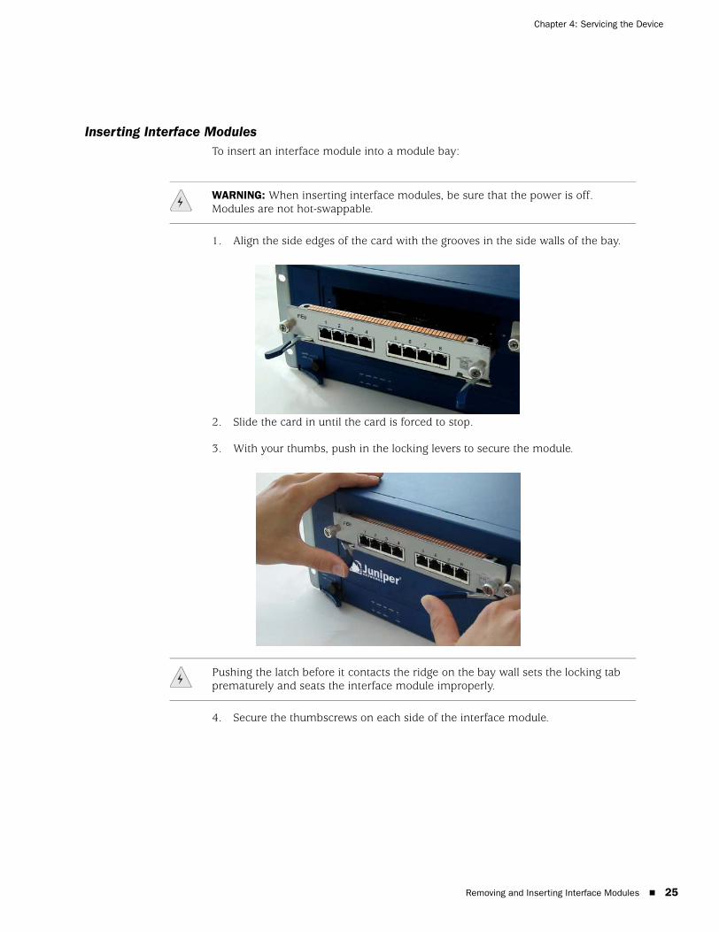
Inserting Interface ModulesTo insert an interface module into a module bay:
1. Align the side edges of the card with the grooves in the side walls of the bay.
2. Slide the card in until the card is forced to stop.
3. With your thumbs, push in the locking levers to secure the module.
4. Secure the thumbscrews on each side of the interface module.
WARNING: When inserting interface modules, be sure that the power is off. Modules are not hot-swappable.
Pushing the latch before it contacts the ridge on the bay wall sets the locking tab prematurely and seats the interface module improperly.
Removing and Inserting Interface Modules 25

ISG 1000 User’s Guide
26
Replacing a DC Power Supply
To replace the DC power supply unit (PSU):
1. Turn off the current and the PSU.
2. Loosen the three retaining screws on the terminal block.
3. Remove the feed wires.
4. Turn the thumbscrews counterclockwise to release the PSU.
5. Lift the handle and, gripping the handle, gently pull the PSU straight out.
6. Insert the new PSU into the bay.
7. Secure the PSU by tightening the thumbscrews clockwise.
8. Insert the 0V DC (positive voltage) return wire into the center COM connector and the -48V DC power feed wire into either the left or the right connector.
9. Fasten the screws over the connectors.
10. Turn on the PSU.
11. Turn on the power switch.
Replacing an AC Power Supply
To replace an AC power supply unit (PSU):
1. Turn off the PSU.
2. Unplug the cord from the PSU.
3. Turn the thumbscrews counterclockwise to release the PSU.
4. Lift the handle and, gripping the handle, gently pull the PSU straight out.
5. Insert the new PSU into the bay.
6. Secure the PSU by tightening the thumbscrews clockwise.
7. Plug the power cord into the PSU.
8. Turn on the PSU.
WARNING: You must shut off current to the DC feed wires leading to the power supply. Also, make sure that the ON/OFF switch on the power supply is in the OFF position.
Replacing a DC Power Supply

Chapter 4: Servicing the Device
Replacing the Fan Tray
You need to replace the fan tray when a failure occurs. When fan failure occurs, the Fan LED glows red, and the device generates an event alarm and an SNMP trap.
To remove the fan tray:
1. Pull the fan lever until it is fully extended.
2. Grip the sides, then gently slide the assembly straight out.
3. Insert the new fan tray in the fan bay, then push it straight in.
4. Secure the fan tray in place by pushing the fan lever flat against the front panel.
Replacing the Fan Tray Filter
Before you replace the fan tray filter, make sure you have the following tools:
Flashlight or other light source
18-inch wooden ruler or at least a 45-centimeter length of wooden dowel
NOTE: During the one-year warranty period, you can obtain a replacement fan tray by contacting the Juniper Customer Support Center. After the warranty period, contact the Juniper Networks Sales department.
WARNING: If a fan stops operating as a result of failure or removal, the system continues to run. Do not leave the fan tray empty for more than two minutes; otherwise, heat failure or permanent damage can occur.
WARNING: Do not remove the fan tray while the fans are still spinning.
Replacing the Fan Tray 27

ISG 1000 User’s Guide
28
To replace the fan tray filter:
1. Pull the fan lever until it is fully extended.
2. Grip the sides, then gently slide the assembly straight out.
3. Pull the front edge of the filter from the Velcro backing.
4. Insert a wooden ruler between the filter and the chassis wall.
5. Push the wooden ruler toward the back of the chassis, gently lifting the filter as you proceed.
6. Once the filter is separated from the Velcro backing, use your fingers to pull the filter out of the fan tray slot.
7. Carefully insert a new filter into the chassis. Use the wooden ruler as an aid to guide the back edge of the filter to the end of the Velcro wall.
8. Once the filter is fully inserted, push the wooden ruler against the filter surface several times to ensure that the filter is secure against the chassis wall.
CAUTION: Use caution when removing the fan tray and fan filter.
Replacing the Fan Tray Filter

Chapter 4: Servicing the Device
9. Insert the fan tray into the chassis.
10. Secure the fan tray by pushing the fan lever flat against the front panel.
Installing Gigabit Ethernet Cables
To connect a gigabit Ethernet cable to a mini-GBIC connector transceiver port:
1. Hold the cable clip firmly but gently between your thumb and forefinger, with your thumb on top of the clip and your finger under the clip. (Do not depress the clip ejector on top of the clip.)
2. Slide the clip into the transceiver port until it clicks into place. Because the fit is close, you may have to apply some force to insert the clip. To avoid clip breakage, apply force evenly and gently.
Removing Gigabit Ethernet Cables
To remove the cable from a mini-GBIC transceiver port:
1. Make sure the transceiver ejector is in a locked position (the lever is flat against the front panel). Otherwise, when you attempt to remove the cable, the transceiver might come out with the cable still attached.
2. Hold the cable clip firmly but gently between your thumb and forefinger, with your thumb on top of the clip and your finger under the clip.
3. Using your thumb, gently press the clip ejector on top of the clip, first down, then forward. This action loosens the clip from the transceiver port.
4. Gently but firmly pull the clip from the transceiver port.
Installing a Mini-GBIC Transceiver
To install a mini-GBIC transceiver into a module:
1. Grasp the transceiver with the label facing up, then insert it into the transceiver slot.
2. Check to see if the transceiver ejector extends fully out to the front of the ejector slot, then align it with the port portion of the transceiver.
CAUTION: Make sure that the filter is secure against the Velcro wall; otherwise, the filter will tear when you reinstall the fan tray.
Installing Gigabit Ethernet Cables 29

ISG 1000 User’s Guide
30
Removing a Mini-GBIC Transceiver
To remove a mini-GBIC transceiver from a module:
1. Push in the ejector (located on the underside of the transceiver) until it locks into place, disengaging the transceiver.
2. Grasp the transceiver on both sides and firmly but gently pull the transceiver toward you to remove it from the module.
Removing a Mini-GBIC Transceiver

Appendix A
Specifications
This appendix provides general system specifications for the ISG 1000:
“ISG 1000 Device Attributes” on page A-I
“Electrical Specification” on page A-I
“Environmental” on page A-II
“Certifications” on page A-II
“Connectors” on page A-II
ISG 1000 Device Attributes
Height: 5.25 inches (13.34 centimeters)
Depth: 18.25 inches (46.36 centimeters)
Width: 17.50 inches (44.45 centimeters)
Weight: 36 pounds (16.3 kilograms) with two modules and PSU
Electrical Specification
AC voltage: 100 - 240 VAC +/- 10%
DC voltage: -36 to -72 VDC
AC Power: 250 watts
DC Power: 250 watts
AC Input frequency: 50-60 Hz
Fuse Rating: DC PS: 10 amps / 250 volts; AC PS: 5 amps / 250 volts
A-I

ISG 1000 User’s Guide
A-II
Environmental
At altitudes up to 10,000 feet (0-3,048 meters), the ISG 1000 system operates in environments kept between 32 and 122°F (0°- 50° C) with 10-90% non-condensing relative humidity.
Certifications
Connectors
The mini-Gigabit transceivers are compatible with the IEEE 802.3z Gigabit Ethernet standard. The following table lists media types and distances for the different types of interfaces used in the ISG 1000 system.
Certification Type Certification Name
NEBS NEBS Level 3 NS-ISG 1000 with DC power supply
GR-63-Core: NEBS, Environmental Testing
GR-1089-Core: EMC and Electrical Safety for Network Telecommunications Equipment
Safety CSA, UL, CUL, CB
EMI FCC class A, BSMI, CE class A, C-Tick, VCCI Class A
Pin Signal DIR
1 RTS OUT
2 DTR OUT
3 TX OUT
4 GND —
5 N.C. —
6 RX IN
7 DSR IN
8 CTS IN
Standard Media Type Maximum Distance (in meters)
1000 Base-SX 50/125 m Multimode Fiber 500
50/125 m Multimode Fiber 550
62.5/125 m Multimode Fiber 220
62.5/125 m Multimode Fiber 275
1000 Base-LX 50/125 m Multimode Fiber 550
62.5/125 m Multimode Fiber 550
9/125 m Single-Mode Fiber 10,000
100 Base-TX Category 5 and higher UTP cable 100
1000 Base-TX Category 5e and higher UTP cable —
µ
µ
µ
µ
µ
µ
µ

Index
AAC power supply.................................................................6admin name, changing .....................................................17ALARMconfiguring ................................................................21LED .............................................................................2
Ccabling
network interfaces...............................................13, 15power supply.............................................................13
changing admin name and password ...............................17CLI commands
get interface ..............................................................19set admin name ........................................................17set admin password ..................................................17set chassis audible-alarm...........................................21set interface ip..........................................................19set interface zone .....................................................19set interface mgt ip ...................................................17
CLI sessionchanging timeout ......................................................15using dialup...............................................................16
console connectionadapter......................................................................14interface ......................................................................5
DDC power supply ................................................................6dialup connection .............................................................16
Ffan
LED .............................................................................3replacing tray ............................................................27tray..............................................................................5
fan filter replacement .......................................................27FLASH
LED .............................................................................3overview......................................................................4
Hhigh availability (HA)
configuring ................................................................21LED .............................................................................3overview......................................................................5
Iinstallation procedure
front-mount .................................................................8mid-mount ..................................................................8
installing modules...............................................................5interface modules ...............................................................3interface settings, viewing.................................................19
LLEDs ...................................................................................2logging on.........................................................................16
Mmanagement interface (MGT)..............................................5management session ........................................................16modem.............................................................................16modem interface ................................................................5modules
high availability ...........................................................5LEDs............................................................................3removing ...................................................................24
NNetwork Address Translation (NAT) ...................................12network configuration.......................................................13
Ooperation
Layer-2 bridge ...........................................................12Layer-3 router............................................................12
Ppassword
changing....................................................................17resetting ....................................................................22
power supply unit (PSU)AC replacement .........................................................26DC replacement.........................................................26overview......................................................................6
Rremote management session ............................................16reset..................................................................................22restoring access ................................................................22Route mode ......................................................................12
Index I
ISG 1000 User’s Guide
II
Ssafety guidelines................................................................. 7security zone .................................................................... 12serial connection .............................................................. 16setting
policies...................................................................... 20Trust IP address ........................................................ 19Untrust IP address..................................................... 20
STATUS LED........................................................................ 3
TTemperature
environmental guidelines ............................................ 7LED ............................................................................. 2
Transparent mode ............................................................ 12
Vviewing interface settings ................................................. 19viewing port settings ........................................................ 19
Wweb management............................................................. 16
Index