isdn to v24 converter
TRANSCRIPT
8/10/2019 ISDN to V24 Converter
http://slidepdf.com/reader/full/isdn-to-v24-converter 1/17
AUSG 01
Descri tionConverter ISDN/V.24 3CR 31036 BAAA DEAFA 1/17
All rights reserved. Passing on and copying of this document,use and communication of its content not permitted without written authorisation
Thales Rail Signalling Solutions GmbH
File: 3CR_31036_BAAA_DEAFA_01.doc
01 25.10.07 TS/AEE, R.Klemm TS/EH, K.Oldewurtel
Rev. Date MTNR STEK, VSB Checked
8/10/2019 ISDN to V24 Converter
http://slidepdf.com/reader/full/isdn-to-v24-converter 2/17
AUSG 01
Descri tionConverter ISDN/V.24 3CR 31036 BAAA DEAFA 2/17
Revisions and change reasons
Rev. Date VSB Change reason
01 25.10.07 Klemm Translation from 3CR 31036 BAAA DEAFC Rev. 01
8/10/2019 ISDN to V24 Converter
http://slidepdf.com/reader/full/isdn-to-v24-converter 3/17
AUSG 01
Descri tionConverter ISDN/V.24 3CR 31036 BAAA DEAFA 3/17
Contents
1 INTRODUCTION........................................................................................................................... 5
1.1 Scope .......................................................................................................................................5
1.2 General ....................................................................................................................................5
1.3 Abbreviations .......................................................................................................................... 5
2 MECHANICAL FEATURES ............................................................................................................ 6
2.1 Housing.....................................................................................................................................6
2.2 Position of clamps and LEDs..................................................................................................6
3 ELECTRICAL FEATURES ................................................................................................................ 7
3.1 Power supply ........................................................................................................................... 7
3.1.1 Connections .................................................................................................................... 7
3.1.2 LED displays...................................................................................................................... 7
3.2 Data transmission (ISDN)........................................................................................................8
3.2.1 Distance ........................................................................................................................... 8
3.2.2 Connections .................................................................................................................... 8
3.2.3 LED displays...................................................................................................................... 8
3.3 Interface (V.24) ....................................................................................................................... 9
3.3.1 Maximum cable length..................................................................................................9
3.3.2 Connections .................................................................................................................... 9
3.3.3 LED displays...................................................................................................................... 9
3.4 Remote power supply ..........................................................................................................10
3.4.1 Connections ..................................................................................................................10
3.4.2 LED displays....................................................................................................................10
3.5 Air and creeping distances, test voltage..........................................................................10
4 BLOCK DIAGRAM..................................................................................................................... 11
5 OPERATION............................................................................................................................... 11
5.1 Properties of ISDN .................................................................................................................11
5.2 Variants of the converter.....................................................................................................11
5.3 Sample applications of the converter ..............................................................................12
5.3.1 Connection of Detection Points to a transmission system......................................12
5.3.1.1 Converter with one Detection Point (locally fed) ............................................12
5.3.1.2 Converter with two Detection Point (DP 1 fed via data line).........................14
5.3.2 Connection of an ACE to a transmission system...................................................... 15
8/10/2019 ISDN to V24 Converter
http://slidepdf.com/reader/full/isdn-to-v24-converter 4/17
AUSG 01
Descri tionConverter ISDN/V.24 3CR 31036 BAAA DEAFA 4/17
5.3.3 Repeater ........................................................................................................................16
5.3.3.1 Repeater with local power supply ..................................................................... 16
5.3.3.2 Repeater fed via data line from ACE ................................................................17
8/10/2019 ISDN to V24 Converter
http://slidepdf.com/reader/full/isdn-to-v24-converter 5/17
AUSG 01
Descri tionConverter ISDN/V.24 3CR 31036 BAAA DEAFA 5/17
1 INTRODUCTION
1.1 Scope
This document describes the printed circuit boards Converter ISDN/V.24 with the followingpart numbers:
Part number Item variants
3CR 31036 BAAA Converter ISDN/V24, LT/LT
3CR 31036 BBAA Converter ISDN/V24, NT/LT
3CR 31036 BCAA Converter ISDN/V24, LT/NT
3CR 31036 BDAA Converter ISDN/V24, NT/NT
1.2 General
The converter changes the physical protocol from ISDN signals (2B1Q Coding) to V.24 andvice versa. Two independent ISDN channels are implemented which are configured in thefour different item variants in all combinations of the ISDN modes (LT or NT). Each ISDNchannel offers two V.24 channels B1 and B2.The converter can be supplied from an external power supply voltage or via one of thedata lines.The housing is created for top hat rail mounting.
1.3 Abbreviations
2B1Q Coding mode of ISDN
AC Alternating currentACE Axle Counter EvaluatorCCITT Comité Consultatif International Téléfonique e TélégraphiqueCTS Clear to sendDSR Data set readyDTR Data terminal readyEAK Elektronic-Junction-BoxGND GroundISDN Integrated Services Digital NetworkLED Light emitting diodeLT Line Termination mode of ISDN
NT Network Termination mode of ISDNRTS Request to sendRXD Receive dataTXD Transmit dataV.24 Physical protocol according to CCITT
8/10/2019 ISDN to V24 Converter
http://slidepdf.com/reader/full/isdn-to-v24-converter 6/17
AUSG 01
Descri tionConverter ISDN/V.24 3CR 31036 BAAA DEAFA 6/17
2 MECHANICAL FEATURES
2.1 Housing
Dimensions (HxWxD): 50 x 128 x 215 mm3
Weight: appr. 800 grMounting: at 35 mm top hat rail
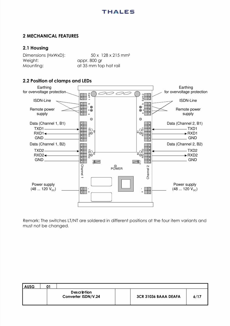
2.2 Position of clamps and LEDs
Remark: The switches LT/NT are soldered in different positions at the four item variants andmust not be changed.
C h a
nn el 1
C h a n n
e l 2
+ + - -
+ -
+ -
T X 1
R X 1
T X 2
R X 2
a
b
E a r t h
2
a
b
E ar t h 1
T X 1 R X 1
T X 2 R X 2
POWER
N T L T
N T
L T
B 1
B 2
B 1
B 2
Earthingfor overvoltage protection
ISDN-Line
Remote power
supply
Earthingfor overvoltage protection
ISDN-Line
Remote power
supply
Data (Channel 1, B1)
TXD1RXD1GND
Data (Channel 1, B2)
TXD2RXD2GND
Data (Channel 2, B1)
TXD1RXD1GND
Data (Channel 2, B2)
TXD2RXD2GND
Power supply(48 ... 120 VDC)
Power supply(48 ... 120 VDC)
8/10/2019 ISDN to V24 Converter
http://slidepdf.com/reader/full/isdn-to-v24-converter 7/17
AUSG 01
Descri tionConverter ISDN/V.24 3CR 31036 BAAA DEAFA 7/17
3 ELECTRICAL FEATURES
3.1 Power supply
An insulated switching power supply is integrated.Voltage range: 48 VDC ... 120 VDC –10%, +5%Fuse: T 1,6 APower consumption: max. 2,5 Watt
3.1.1 Connections
The connections for power supply are using clamp terminals (cross section: 0,08 mm2 to2,5 mm2).Two parallel double clamps are available:
Name at block with 2 clamps Signal
+ Positive supply voltage – Negative supply voltage
3.1.2 LED displays
In the center of the converter there is a green LED which shows the presence of the inputvoltage for power supply.
8/10/2019 ISDN to V24 Converter
http://slidepdf.com/reader/full/isdn-to-v24-converter 8/17
AUSG 01
Descri tionConverter ISDN/V.24 3CR 31036 BAAA DEAFA 8/17
3.2 Data transmission (ISDN)
Required wires: 2Data rate: max. 19,2 kBd (asynchronious)Coding: ISDN 2B1Q
Attenuation: max. 24 dB (at 40 kHz)
3.2.1 Distance
The maximum distance for data transmission depends from the attenuation of the com-munication path which must not exceed 24 dB (at 40 kHz) including all cables, clampsand transformers.
Typical attenuation (at 40kHz):
Copper diameter Attenuation Maximum distance (without transformers)
0,9 mm 2,6 dB/km 9,2 km
1,4 mm 2,0 dB/km 12 km
3.2.2 Connections
Clamp terminals (cross section: 0,08 mm2 to 2,5 mm2) are used.In each channel the following clamps are available:
Name at block with 4 clamps Signal
A ISDN line a
+ Positive remote power supply voltage
– Negative remote power supply voltageB ISDN line b
3.2.3 LED displays
The LEDs „Ltg1 OK“ and „Ltg2 OK“ are showing that the ISDN connection of the accordingISDN line is established. Only then data transmission is possible.
8/10/2019 ISDN to V24 Converter
http://slidepdf.com/reader/full/isdn-to-v24-converter 9/17
AUSG 01
Descri tionConverter ISDN/V.24 3CR 31036 BAAA DEAFA 9/17
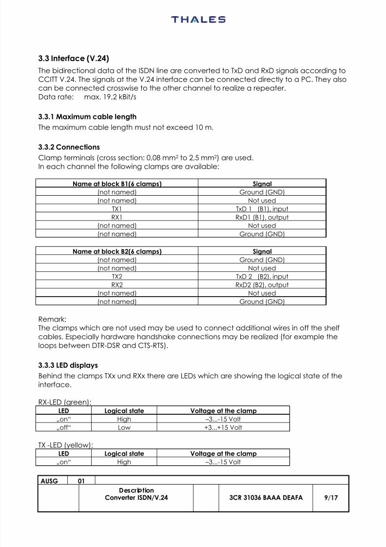
3.3 Interface (V.24)
The bidirectional data of the ISDN line are converted to TxD and RxD signals according toCCITT V.24. The signals at the V.24 interface can be connected directly to a PC. They alsocan be connected crosswise to the other channel to realize a repeater.
Data rate: max. 19,2 kBit/s
3.3.1 Maximum cable length
The maximum cable length must not exceed 10 m.
3.3.2 Connections
Clamp terminals (cross section: 0,08 mm2 to 2,5 mm2) are used.In each channel the following clamps are available:
Name at block B1(6 clamps) Signal
(not named) Ground (GND)(not named) Not used
TX1 TxD 1 (B1), input
RX1 RxD1 (B1), output
(not named) Not used
(not named) Ground (GND)
Name at block B2(6 clamps) Signal
(not named) Ground (GND)
(not named) Not used
TX2 TxD 2 (B2), input
RX2 RxD2 (B2), output(not named) Not used
(not named) Ground (GND)
Remark:The clamps which are not used may be used to connect additional wires in off the shelfcables. Especially hardware handshake connections may be realized (for example theloops between DTR-DSR and CTS-RTS).
3.3.3 LED displays
Behind the clamps TXx und RXx there are LEDs which are showing the logical state of the
interface.
RX-LED (green):LED Logical state Voltage at the clamp
„on“ High –3...-15 Volt
„off“ Low +3...+15 Volt
TX -LED (yellow):LED Logical state Voltage at the clamp
„on“ High –3...-15 Volt
8/10/2019 ISDN to V24 Converter
http://slidepdf.com/reader/full/isdn-to-v24-converter 10/17
AUSG 01
Descri tionConverter ISDN/V.24 3CR 31036 BAAA DEAFA 10/17
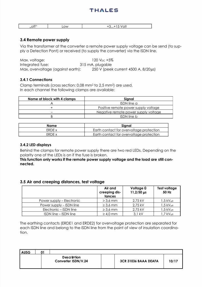
„off“ Low +3...+15 Volt
3.4 Remote power supply
Via the transformer at the converter a remote power supply voltage can be send (to sup-
ply a Detection Pont) or received (to supply the converter) via the ISDN line.
Max. voltage: 120 VDC +5%Integrated fuse: 315 mA, plugableMax. overvoltage (against earth): 250 V (peek current 4500 A, 8/20 µs)
3.4.1 Connections
Clamp terminals (cross section: 0,08 mm2 to 2,5 mm2) are used.In each channel the following clamps are available:
Name at block with 4 clamps SignalA ISDN line a
+ Positive remote power supply voltage
– Negative remote power supply voltage
B ISDN line b
Name Signal
ERDE x Earth contact for overvoltage protection
ERDE x Earth contact for overvoltage protection
3.4.2 LED displays
Behind the clamps for remote power supply there are two red LEDs. Depending on thepolarity one of the LEDs is on if the fuse is broken.This function only works if the remote power supply voltage and the load are still con-nected.
3.5 Air and creeping distances, test voltage
Air andcreeping dis-
tances
Voltage ÛÛÛÛ 11,2/50 µµµµs
Test voltage50 Hz
Power supply – Electronic ≥ 3,6 mm 2,75 kV 1,5 kVeff Power supply – ISDN line ≥ 3,6 mm 2,75 kV 1,5 kVeff
Electronic – ISDN line ≥ 3,6 mm 2,75 kV 1,5 kVeff
ISDN line – ISDN line ≥ 4,0 mm 3,1 kV 1,7 kVeff
The earthing contacts (ERDE1 and ERDE2) for overvoltage protection are separated foreach ISDN line and belong to the ISDN line from the point of view of insulation coordina-tion.
8/10/2019 ISDN to V24 Converter
http://slidepdf.com/reader/full/isdn-to-v24-converter 11/17
AUSG 01
Descri tionConverter ISDN/V.24 3CR 31036 BAAA DEAFA 11/17
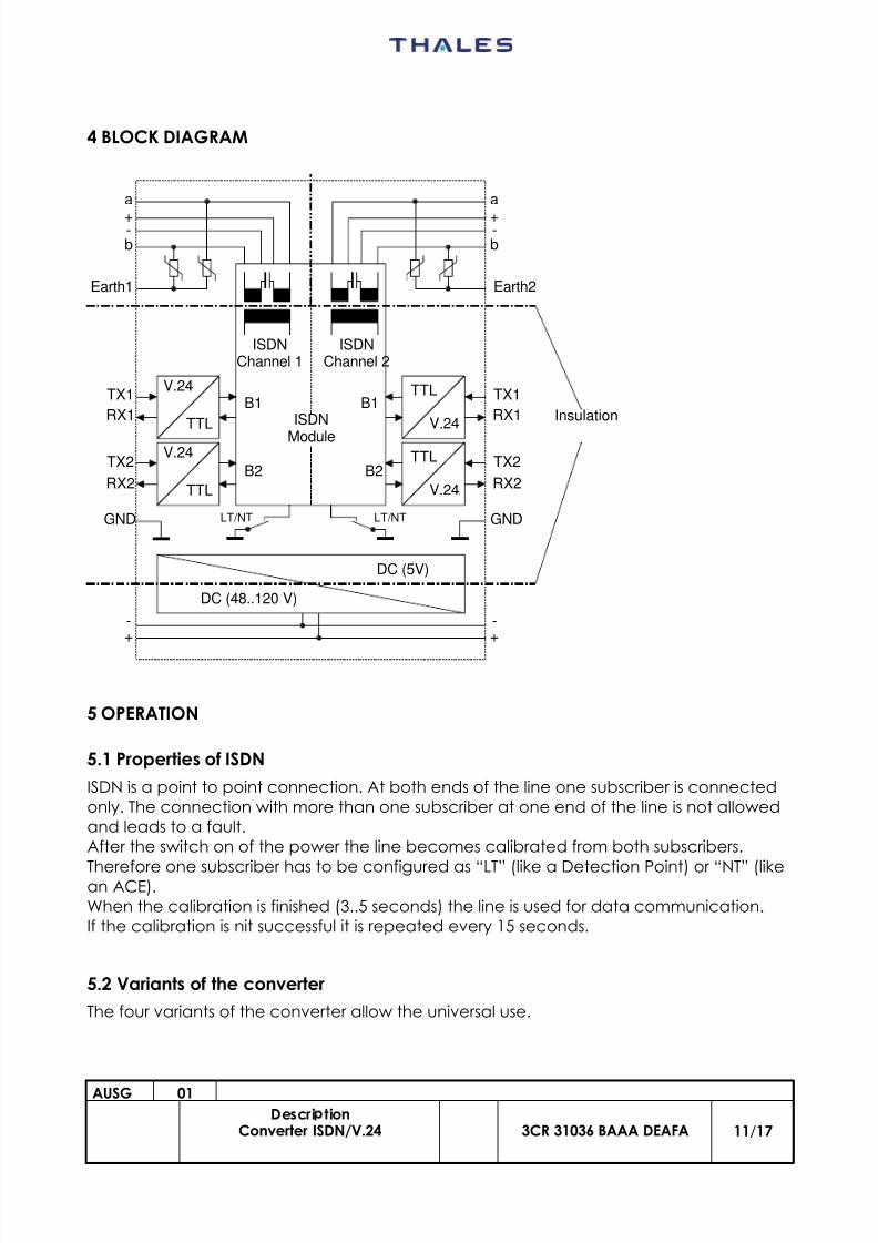
4 BLOCK DIAGRAM
5 OPERATION
5.1 Properties of ISDN
ISDN is a point to point connection. At both ends of the line one subscriber is connectedonly. The connection with more than one subscriber at one end of the line is not allowedand leads to a fault.After the switch on of the power the line becomes calibrated from both subscribers.
Therefore one subscriber has to be configured as “LT” (like a Detection Point) or “NT” (likean ACE).When the calibration is finished (3..5 seconds) the line is used for data communication.If the calibration is nit successful it is repeated every 15 seconds.
5.2 Variants of the converter
The four variants of the converter allow the universal use.
ISDN
Module
ISDNChannel 1
ISDNChannel 2
B1B1
B2B2
TTL
V.24
TTL
V.24TTL
V.24
TTL
V.24
DC (5V)
DC (48..120 V)
a
b
+-
Earth1
a
b
+-
Earth2
+-
+-
TX1
RX1
TX2
RX2
TX1
RX1
TX2
RX2
Insulation
LT/NT LT/NTGND GND
8/10/2019 ISDN to V24 Converter
http://slidepdf.com/reader/full/isdn-to-v24-converter 12/17
AUSG 01
Descri tionConverter ISDN/V.24 3CR 31036 BAAA DEAFA 12/17
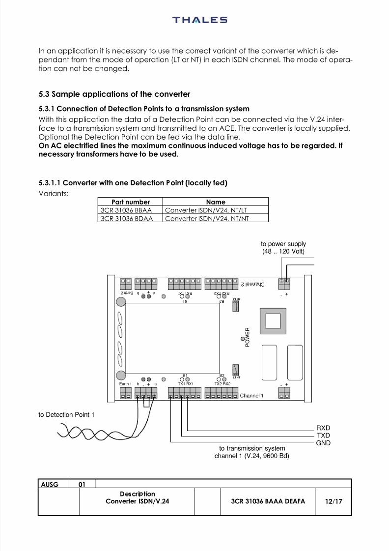
In an application it is necessary to use the correct variant of the converter which is de-pendant from the mode of operation (LT or NT) in each ISDN channel. The mode of opera-tion can not be changed.
5.3 Sample applications of the converter5.3.1 Connection of Detection Points to a transmission system
With this application the data of a Detection Point can be connected via the V.24 inter-face to a transmission system and transmitted to an ACE. The converter is locally supplied.Optional the Detection Point can be fed via the data line.On AC electrified lines the maximum continuous induced voltage has to be regarded. Ifnecessary transformers have to be used.
5.3.1.1 Converter with one Detection Point (locally fed)
Variants:Part number Name
3CR 31036 BBAA Converter ISDN/V24, NT/LT
3CR 31036 BDAA Converter ISDN/V24, NT/NT
Channel 1
C h a n n e l 2
+
+
-
-
+ -
+ - T X 1 R X 1 T X 2 R X 2 a b E a r t h 2
abEarth 1 TX1 RX1 TX2 RX2
P O W E R
NTLTB1 B2
B 1 B 2 N T L T
to Detection Point 1
RXDTXDGND
to power supply(48 .. 120 Volt)
to transmission systemchannel 1 (V.24, 9600 Bd)
8/10/2019 ISDN to V24 Converter
http://slidepdf.com/reader/full/isdn-to-v24-converter 13/17
AUSG 01
Descri tionConverter ISDN/V.24 3CR 31036 BAAA DEAFA 13/17
8/10/2019 ISDN to V24 Converter
http://slidepdf.com/reader/full/isdn-to-v24-converter 14/17
AUSG 01
Descri tionConverter ISDN/V.24 3CR 31036 BAAA DEAFA 14/17
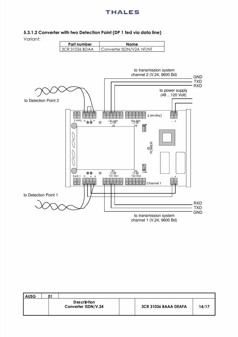
5.3.1.2 Converter with two Detection Point (DP 1 fed via data line)
Variant:Part number Name
3CR 31036 BDAA Converter ISDN/V24, NT/NT
Channel 1
C h a n n e l 2
+
+
-
-
+ -
+ - T X 1 R X 1 T X 2 R X 2 a b E a r t h 2
abEarth 1 TX1 RX1 TX2 RX2
P O W E R
NTLTB1 B2
B 1 B 2 N T L T
to Detection Point 2
to Detection Point 1
RXDTXDGND
to power supply(48 .. 120 Volt)
to transmission systemchannel 1 (V.24, 9600 Bd)
to transmission systemchannel 2 (V.24, 9600 Bd)
RXDTXDGND
8/10/2019 ISDN to V24 Converter
http://slidepdf.com/reader/full/isdn-to-v24-converter 15/17
AUSG 01
Descri tionConverter ISDN/V.24 3CR 31036 BAAA DEAFA 15/17
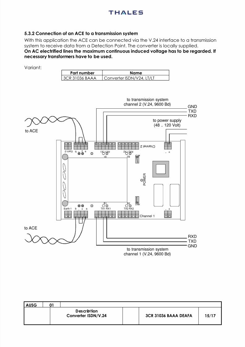
5.3.2 Connection of an ACE to a transmission system
With this application the ACE can be connected via the V.24 interface to a transmissionsystem to receive data from a Detection Point. The converter is locally supplied.On AC electrified lines the maximum continuous induced voltage has to be regarded. Ifnecessary transformers have to be used.
Variant:Part number Name
3CR 31036 BAAA Converter ISDN/V24, LT/LT
Channel 1
C h a n n e l 2
+
+
-
-
+ -
+ - T X 1 R X 1 T X 2 R X 2 a b E a r t h 2
abEarth 1 TX1 RX1 TX2 RX2
P O
W E R
NTLTB1 B2
B 1 B 2 N T L T
to ACE
to ACE
RXD
TXDGND
to power supply(48 .. 120 Volt)
to transmission systemchannel 1 (V.24, 9600 Bd)
to transmission systemchannel 2 (V.24, 9600 Bd)
RXDTXDGND
8/10/2019 ISDN to V24 Converter
http://slidepdf.com/reader/full/isdn-to-v24-converter 16/17
AUSG 01
Descri tionConverter ISDN/V.24 3CR 31036 BAAA DEAFA 16/17
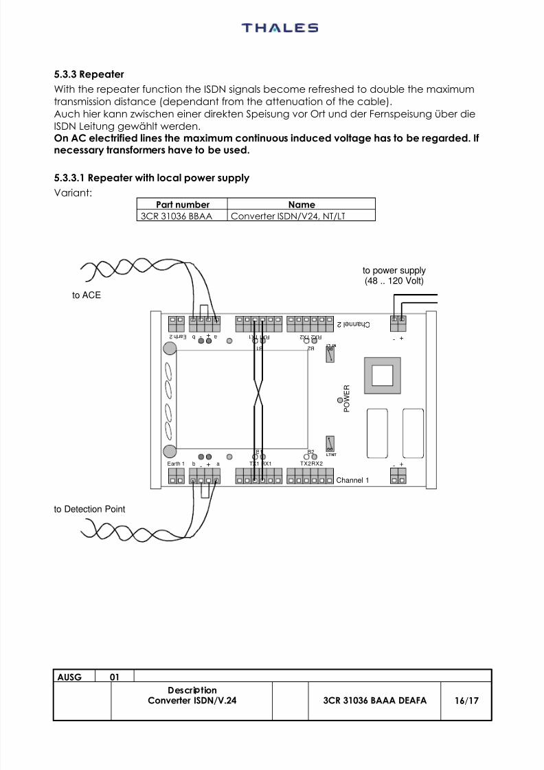
5.3.3 Repeater
With the repeater function the ISDN signals become refreshed to double the maximumtransmission distance (dependant from the attenuation of the cable).Auch hier kann zwischen einer direkten Speisung vor Ort und der Fernspeisung über dieISDN Leitung gewählt werden.
On AC electrified lines the maximum continuous induced voltage has to be regarded. Ifnecessary transformers have to be used.
5.3.3.1 Repeater with local power supply
Variant:Part number Name
3CR 31036 BBAA Converter ISDN/V24, NT/LT
Channel 1
C h a n n e l 2
+
+
-
-
+ -
+ - T X 1 R X 1 T X 2 R X 2 a b E a r t h 2
abEarth 1 TX1 RX1 TX2RX2
P O
W E R
NTLTB1 B2
B 1 B 2 N T L T
to power supply(48 .. 120 Volt)
to Detection Point
to ACE
8/10/2019 ISDN to V24 Converter
http://slidepdf.com/reader/full/isdn-to-v24-converter 17/17
AUSG 01
Descri tionConverter ISDN/V.24 3CR 31036 BAAA DEAFA 17/17
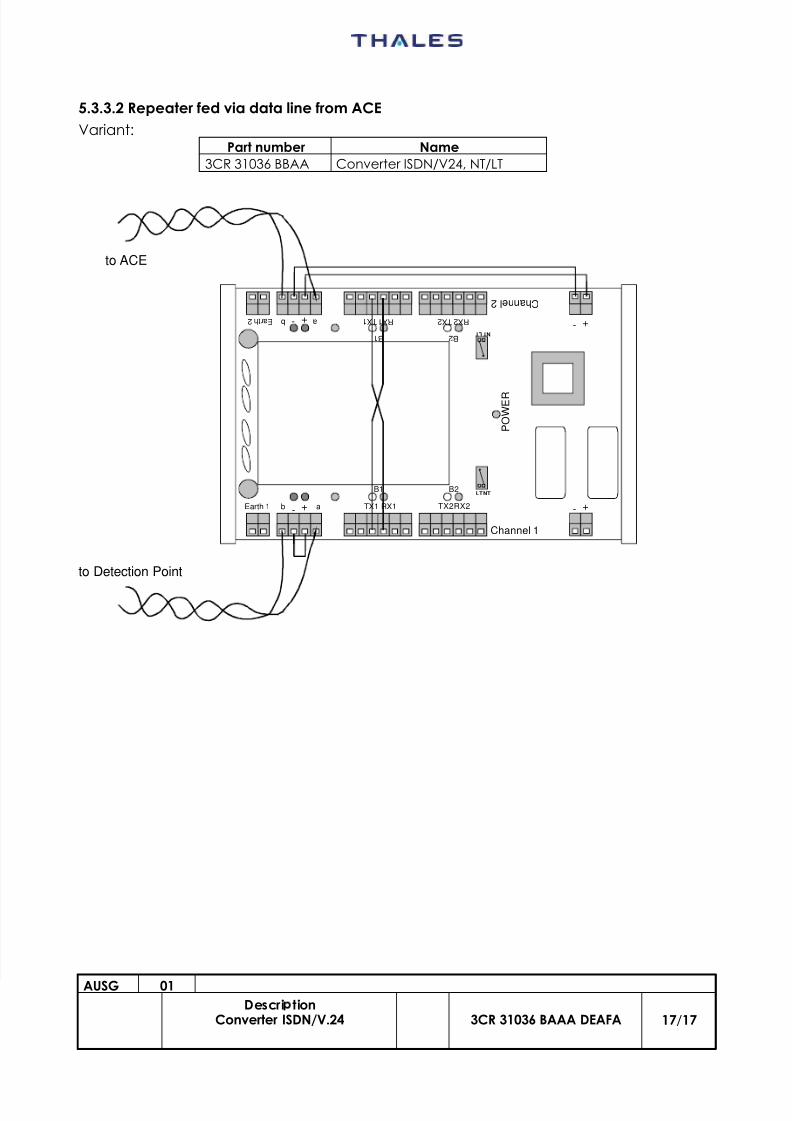
5.3.3.2 Repeater fed via data line from ACE
Variant:Part number Name
3CR 31036 BBAA Converter ISDN/V24, NT/LT
Channel 1
C h a n n e l 2
+
+
-
-
+ -
+ - T X 1 R X 1 T X 2 R X 2 a b E a r t h 2
abEarth 1 TX1 RX1 TX2RX2
P O W E R
NTLTB1 B2
B 1 B 2 N T L T
to Detection Point
to ACE