iscan system guide - illumina · consumables required iscansystemguide 9 consumablesrequired...
TRANSCRIPT
Customize a short end-to-end work�ow guide with the Custom Protocol Selectorsupport.illumina.com/custom-protocol-selector.html
For Research Use Only. Not for use in diagnostic procedures.
August 2015Document # 11313539 v01Material # 20000396Catalog # SY-950-1001DOCILLUMINA PROPRIETARY
iScan System Guide

ii Material # 20000396Document # 11313539 v01
This document and its contents are proprietary to Illumina, Inc. and its affiliates ("Illumina"), and are intended solely for thecontractual use of its customer in connection with the use of the product(s) described herein and for no other purpose. Thisdocument and its contents shall not be used or distributed for any other purpose and/or otherwise communicated, disclosed,or reproduced in any way whatsoever without the prior written consent of Illumina. Illumina does not convey any licenseunder its patent, trademark, copyright, or common-law rights nor similar rights of any third parties by this document.
The instructions in this document must be strictly and explicitly followed by qualified and properly trained personnel in orderto ensure the proper and safe use of the product(s) described herein. All of the contents of this document must be fully readand understood prior to using such product(s).
FAILURE TO COMPLETELY READ AND EXPLICITLY FOLLOW ALL OF THE INSTRUCTIONS CONTAINED HEREINMAY RESULT IN DAMAGE TO THE PRODUCT(S), INJURY TO PERSONS, INCLUDING TO USERS OR OTHERS, ANDDAMAGE TO OTHER PROPERTY.
ILLUMINA DOES NOT ASSUME ANY LIABILITY ARISING OUT OF THE IMPROPER USE OF THE PRODUCT(S)DESCRIBED HEREIN (INCLUDING PARTS THEREOF OR SOFTWARE).
© 2015 Illumina, Inc. All rights reserved.
Illumina, 24sure, BaseSpace, BeadArray, BlueFish, BlueFuse, BlueGnome, cBot, CSPro, CytoChip, DesignStudio,Epicentre, ForenSeq, GAIIx, Genetic Energy, Genome Analyzer, GenomeStudio, GoldenGate, HiScan, HiSeq, HiSeq X,Infinium, iScan, iSelect,, MiSeq, MiSeqDx, MiSeq FGx, NeoPrep, Nextera, NextBio, NextSeq, Powered by Illumina,SeqMonitor, SureMDA, TruGenome, TruSeq, TruSight, Understand Your Genome, UYG, VeraCode, verifi, VeriSeq, thepumpkin orange color, and the streaming bases design are trademarks of Illumina, Inc. and/or its affiliate(s) in the U.S. and/orother countries. All other names, logos, and other trademarks are the property of their respective owners.
RevisionHistory
Document Date Description of Change
Material # 20000396Document # 11313539v01
August2015
Added troubleshooting information for malfunctioning statuslights in the iScan Reader Issues section.
Document # 11313539Rev. B
February2011
Updated to reflect iScan Control Software (ICS) version 3.2,including automated genotype calling functionality and otherfeatures.
Document # 11313539Rev. A
April2008
Part number changed to 11313539.
Document # 11308663Rev. A
April2008
Initial release.
iScan SystemGuide iii

iv Material # 20000396Document # 11313539 v01
[This page intentionally left blank]
Table ofContents
Revision History iiiTable of Contents v
Chapter 1 Overview 1Introduction 2Additional Resources 3Instrument Components 4Consumables Required 9iScan SystemRequirements 10Scanning Process Overview 11
Chapter 2 Starting the iScan System 13Procedure Summary 14Powering up the iScan System 15Starting the iScan Control Software 16Using LIMS with the iScan System 17
Chapter 3 Loading BeadChips 19Procedure Summary 20Cleaning a BeadChip 21Loading BeadChips onto a Carrier 22Loading a Carrier into the iScan Reader 24Rescanning Barcodes 27
Chapter 4 Configuring iScan Control Software 29Introduction 30Omitting BeadChips from a Scan 31Changing Scan Settings 32
Chapter 5 Scanning 35Introduction 36Starting a Scan 37Monitoring the Scan Progress 38Pausing, Resuming, and Stopping a Scan 39Completing a Scan 40
Chapter 6 Viewing Scan Results 41Introduction 42Log Files 43ScanMetrics 44Images 45Generated Files 49
Chapter 7 Shutting Down, Maintenance, and Service 51Introduction 52Shutting Down the iScan System 53Maintenance 54Service 55
iScan SystemGuide v
vi Material # 20000396Document # 11313539 v01
Appendix 8 Troubleshooting 57Handling Errors 58Issue Types 59Registration Issues 60Auto-Alignment Issues 62iScan Reader Issues 64Image Quality Issues 67iScan Control Software Display Issues 69
Index 71
Technical Assistance 73
Chapter1
iScan SystemGuide 1
Chapter 1 Overview
Overview
Introduction 2Additional Resources 3Instrument Components 4Consumables Required 9iScan SystemRequirements 10Scanning Process Overview 11
Overview
2 Material # 20000396Document # 11313539 v01
Introduction
The iScan System is an easy-to-use, laser-based, high-resolution benchtop optical imagingsystem that can rapidly scan and collect large volumes of data from Illumina DNAanalysis and RNA analysis high-density BeadChips.With powerful scanning tools for gene expression and genotyping applications, the iScanSystem supports the rapid, sensitive, and accurate imaging of Illumina BeadChip products.Incorporating the highest performance optics and detection systems, the iScan Systemdelivers outstanding data quality and reproducibility with dramatically reduced scan time.BeadChips are substrates used for multisample analysis in Illumina genotyping and geneexpression applications. Assay features are loaded into wells of a BeadChip to create anorganized array. The iScan System compiles a virtual representation of a BeadChip,acquires images of the BeadChip features, records the information, and exports the data fordownstream analysis.The iScan System can be integrated with Illumina LIMS (laboratory informationmanagement software) and assay automation options, such as the AutoLoader(AutoLoader2 or AutoLoader 2.x model), to maximize throughput to thousands of samplesper day. When used with Infinium® HD BeadChips and the AutoLoader, the iScan Systemcan report up to 225 million genotypes in a single day, offering the fastest path todiscovery.
Audience and PurposeThis guide describes the instrument components, software interface, consumables, andoperational procedures for scanning Illumina BeadChips on the iScan System.This guide is for laboratory personnel and other individuals responsible for:} Operating the iScan System} Performing instrument and component maintenance} Training personnel
WARNINGUsing controls, making adjustments, or performing procedures other than the proceduresspecified in this guide can result in hazardous laser light or radiation exposure.

Additio
nalReso
urces
iScan SystemGuide 3
AdditionalResources
The following documentation is available for download from the Illumina website.
Resource Description
iScan System Site Prep Guide(document # 1000000000661)
Provides specifications for laboratory space, electricalrequirements, and environmental considerations.
iScan System Quick ReferenceCard (part # 11313555)
Provides instructions for starting up and shutting down theiScan system.
iScan System Quick ReferenceGuide (part #15020712)
Provides an overview of instrument components andsoftware, instructions for imaging data on BeadChips, andinstructions for starting up and shutting down the iScansystem.
iScan System Safety andCompliance Guide (part #15022905)
Provides safety information and product compliancestatements for the iScan system.
Visit the iScan System support page on the Illumina website for access to documentation,software downloads, and online training.
Overview
4 Material # 20000396Document # 11313539 v01
InstrumentComponents
The iScan consists of the following components:} iScan Reader} Instrument control computer} BeadChip carrier or carriers} Power cords and other accessories} [Optional] AutoLoader SystemIn addition to these components, purchase BeadChips developed for your application.
iScan Reader
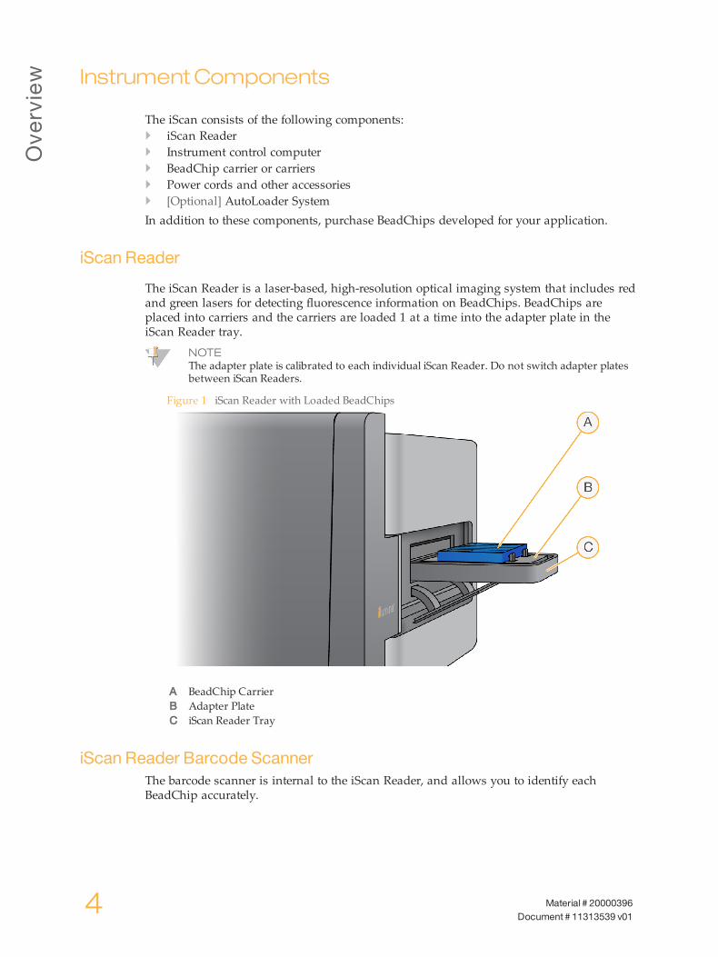
The iScan Reader is a laser-based, high-resolution optical imaging system that includes redand green lasers for detecting fluorescence information on BeadChips. BeadChips areplaced into carriers and the carriers are loaded 1 at a time into the adapter plate in theiScan Reader tray.
NOTEThe adapter plate is calibrated to each individual iScan Reader. Do not switch adapter platesbetween iScan Readers.
Figure 1 iScan Reader with Loaded BeadChips
A BeadChip CarrierB Adapter PlateC iScan Reader Tray
iScan Reader Barcode ScannerThe barcode scanner is internal to the iScan Reader, and allows you to identify eachBeadChip accurately.

Instrument
Components
iScan SystemGuide 5
Status LightsThe iScan Reader status indicator lights and scan bar on the front panel show the status ofthe instrument.
Figure 2 Status Lights and Scan Bar
Status Light Description
Power (blue) Steady blue indicates that the instrument is on.
Ready (greencheck)
Steady green indicates that the instrument has been initialized and is readyto scan. The Ready light flashes during initialization.
Warning(ambertriangle)
Solid amber indicates that an instrument error has occurred. Try cycling thepower.
Scan Bar(vertical blue
bar)
Steady indicates that the instrument is scanning. The Scan Bar is the blueLED pipe to the left of the tray.
iScan Reader TrayThe iScan Reader tray accepts up to 4 BeadChips loaded in a BeadChip carrier.
Instrument Control ComputerThe iScan Control Software (ICS) installed on instrument control computer allows you tocontrol the iScan Reader during BeadChip scanning.
Hard Drive ConfigurationThe iScan System contains 2 permanent drives (C: and D:) on the computer and 1removable drive (H:) within the iScan Reader.Drives C: and D: are physically separate drives; they are not part of 1 large drivepartitioned into 2 drives.
Overview
6 Material # 20000396Document # 11313539 v01
Drive Description
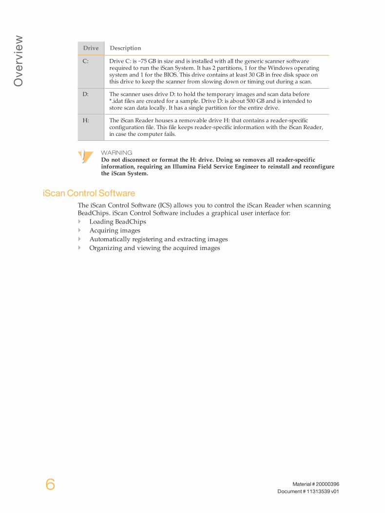
C: Drive C: is ~75 GB in size and is installed with all the generic scanner softwarerequired to run the iScan System. It has 2 partitions, 1 for the Windows operatingsystem and 1 for the BIOS. This drive contains at least 30 GB in free disk space onthis drive to keep the scanner from slowing down or timing out during a scan.
D: The scanner uses drive D: to hold the temporary images and scan data before*.idat files are created for a sample. Drive D: is about 500 GB and is intended tostore scan data locally. It has a single partition for the entire drive.
H: The iScan Reader houses a removable drive H: that contains a reader-specificconfiguration file. This file keeps reader-specific information with the iScan Reader,in case the computer fails.
WARNINGDo not disconnect or format the H: drive. Doing so removes all reader-specificinformation, requiring an Illumina Field Service Engineer to reinstall and reconfigurethe iScan System.
iScan Control SoftwareThe iScan Control Software (ICS) allows you to control the iScan Reader when scanningBeadChips. iScan Control Software includes a graphical user interface for:} Loading BeadChips} Acquiring images} Automatically registering and extracting images} Organizing and viewing the acquired images

Instrument
Components
iScan SystemGuide 7
BeadChip CarriersThe iScan System comes with 1 BeadChip carrier. The carrier holds up to 4 BeadChips forscanning at 1 time.The BeadChip carriers consist of the following components.
Figure 3 BeadChip Carrier
A Latches (closed)B Raised StopsC BeadChip SlotsD Lift ButtonE Recessed Pin
Carrier and BeadChip BarcodesBeadChip carrier barcodes are used to identify the individual BeadChip carriers anddetermine when a BeadChip position is occupied or empty.These barcodes are necessary when performing automated scanning. During automatedscanning, the barcodes enable problem BeadChips to be quickly located in the output orerror stacks. They also tell the scanner when to retry scanning a BeadChip position when itdoes not successfully read a BeadChip barcode on the first attempt.

Overview
8 Material # 20000396Document # 11313539 v01
Figure 4 Top View of BeadChip Carrier Barcode
A Carrier BarcodeB Empty Barcode
Figure 5 Side View of BeadChip Carrier Barcode
If the carrier does not have a barcode number, the carrier barcode number is listed as thebarcode number for the first BeadChip in the carrier.The format for the number is _1stBeadChipBarcode.
Power Cords and Other AccessoriesThe iScan System comes with power and connection cords that are connected for you byauthorized Illumina personnel as part of the system installation. Do not unplug ordisconnect any cords unless instructed by Illumina Technical Support.
Consum
ables
Req
uired
iScan SystemGuide 9
ConsumablesRequired
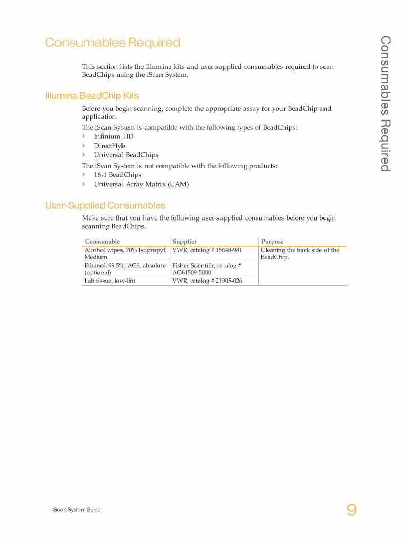
This section lists the Illumina kits and user-supplied consumables required to scanBeadChips using the iScan System.
Illumina BeadChip KitsBefore you begin scanning, complete the appropriate assay for your BeadChip andapplication.The iScan System is compatible with the following types of BeadChips:} Infinium HD} DirectHyb} Universal BeadChipsThe iScan System is not compatible with the following products:} 16-1 BeadChips} Universal Array Matrix (UAM)
User-Supplied ConsumablesMake sure that you have the following user-supplied consumables before you beginscanning BeadChips.
Consumable Supplier PurposeAlcohol wipes, 70% Isopropyl,Medium
VWR, catalog # 15648-981 Cleaning the back side of theBeadChip.
Ethanol, 99.5%, ACS, absolute(optional)
Fisher Scientific, catalog #AC61509-5000
Lab tissue, low-lint VWR, catalog # 21905-026
Overview
10 Material # 20000396Document # 11313539 v01
iScanSystemRequirements
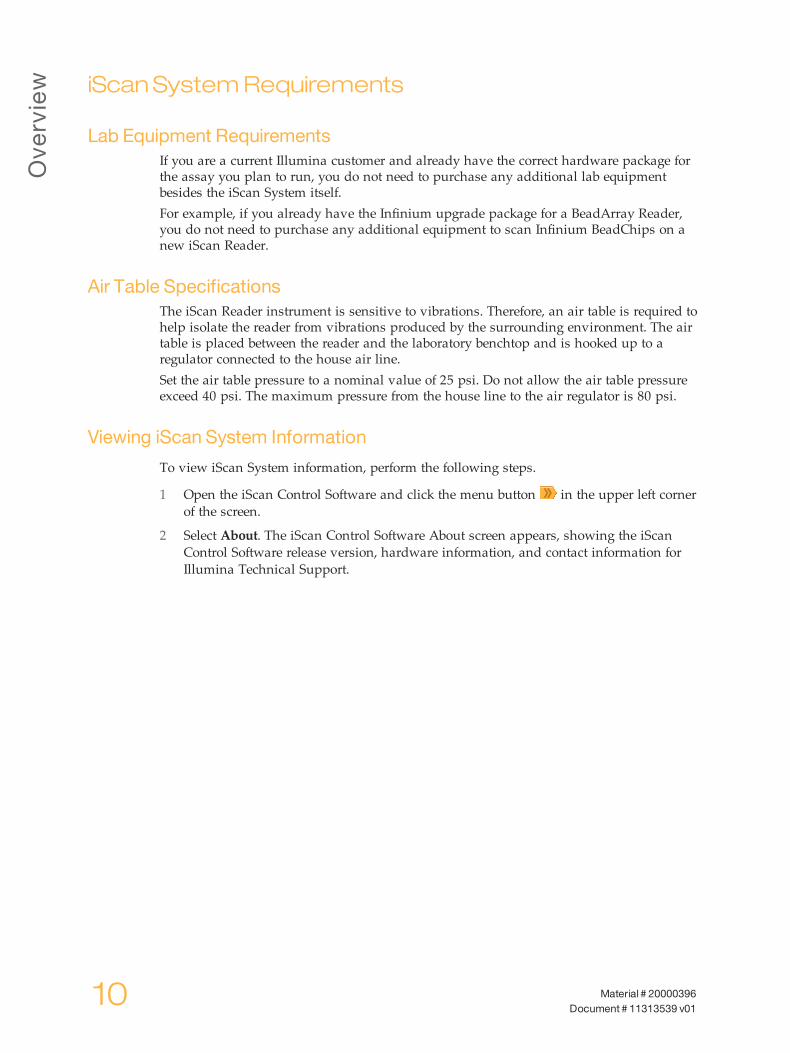
Lab Equipment RequirementsIf you are a current Illumina customer and already have the correct hardware package forthe assay you plan to run, you do not need to purchase any additional lab equipmentbesides the iScan System itself.For example, if you already have the Infinium upgrade package for a BeadArray Reader,you do not need to purchase any additional equipment to scan Infinium BeadChips on anew iScan Reader.
Air Table SpecificationsThe iScan Reader instrument is sensitive to vibrations. Therefore, an air table is required tohelp isolate the reader from vibrations produced by the surrounding environment. The airtable is placed between the reader and the laboratory benchtop and is hooked up to aregulator connected to the house air line.Set the air table pressure to a nominal value of 25 psi. Do not allow the air table pressureexceed 40 psi. The maximum pressure from the house line to the air regulator is 80 psi.
Viewing iScan System Information
To view iScan System information, perform the following steps.
1 Open the iScan Control Software and click the menu button in the upper left cornerof the screen.
2 Select About. The iScan Control Software About screen appears, showing the iScanControl Software release version, hardware information, and contact information forIllumina Technical Support.
Scanning
Process
Overview
iScan SystemGuide 11
ScanningProcessOverview
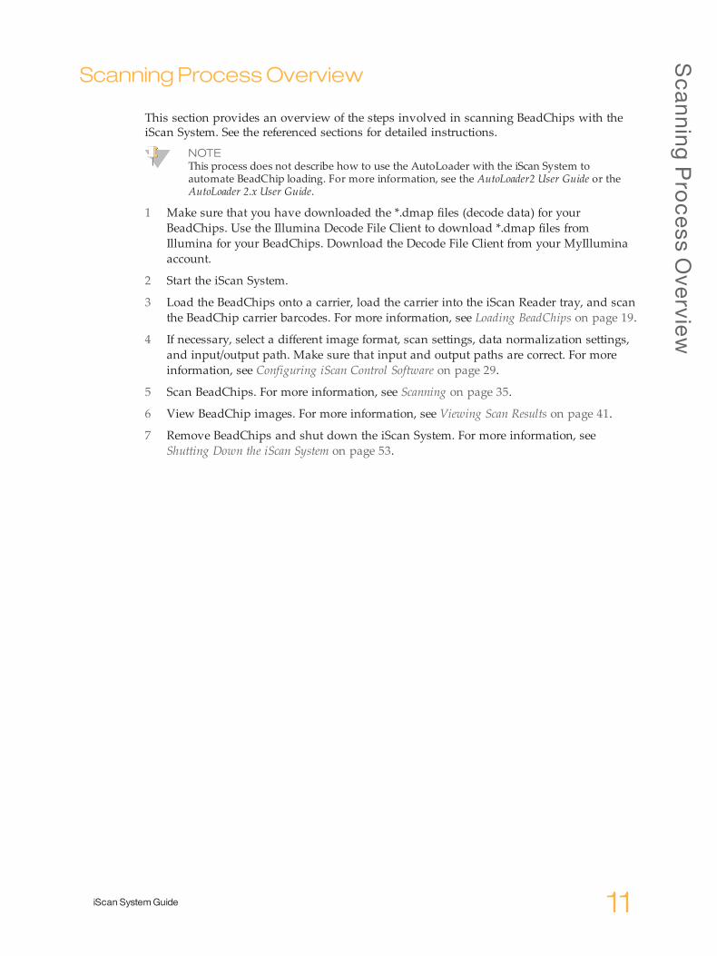
This section provides an overview of the steps involved in scanning BeadChips with theiScan System. See the referenced sections for detailed instructions.
NOTEThis process does not describe how to use the AutoLoader with the iScan System toautomate BeadChip loading. For more information, see the AutoLoader2 User Guide or theAutoLoader 2.x User Guide.
1 Make sure that you have downloaded the *.dmap files (decode data) for yourBeadChips. Use the Illumina Decode File Client to download *.dmap files fromIllumina for your BeadChips. Download the Decode File Client from your MyIlluminaaccount.
2 Start the iScan System.
3 Load the BeadChips onto a carrier, load the carrier into the iScan Reader tray, and scanthe BeadChip carrier barcodes. For more information, see Loading BeadChips on page 19.
4 If necessary, select a different image format, scan settings, data normalization settings,and input/output path. Make sure that input and output paths are correct. For moreinformation, see Configuring iScan Control Software on page 29.
5 Scan BeadChips. For more information, see Scanning on page 35.
6 View BeadChip images. For more information, see Viewing Scan Results on page 41.
7 Remove BeadChips and shut down the iScan System. For more information, seeShutting Down the iScan System on page 53.

12 Material # 20000396Document # 11313539 v01
Chapter2
iScan SystemGuide 13
Chapter 2 Starting the iScan System
Startingthe iScanSystem
Procedure Summary 14Powering up the iScan System 15Starting the iScan Control Software 16Using LIMS with the iScan System 17
StartingtheiScanSystem
14 Material # 20000396Document # 11313539 v01
Procedure Summary
Perform the following steps to start the iScan System.
1 Power up the iScan Reader.
2 Power up the iScan System computer.
3 Start the iScan Control Software.These steps are described in the following sections, along with information on using LIMSwith the iScan System.
Powering
upthe
iScan
System
iScan SystemGuide 15
Poweringup the iScanSystem
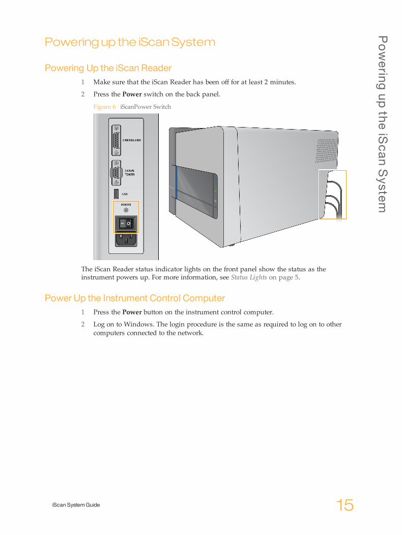
Powering Up the iScan Reader1 Make sure that the iScan Reader has been off for at least 2 minutes.
2 Press the Power switch on the back panel.
Figure 6 iScanPower Switch
The iScan Reader status indicator lights on the front panel show the status as theinstrument powers up. For more information, see Status Lights on page 5.
Power Up the Instrument Control Computer1 Press the Power button on the instrument control computer.
2 Log on to Windows. The login procedure is the same as required to log on to othercomputers connected to the network.
StartingtheiScanSystem
16 Material # 20000396Document # 11313539 v01
Starting the iScanControl Software
NOTEArchive and delete data on the computer on a regular schedule to make sure that sufficientdisk space is available.
1 Double-click the iScan Control Software icon on the computer desktop. The iScanControl Software automatically connects to and initializes the iScan Reader.
2 If your iScan System is configured to work with LIMS, select your LIMS server from thedrop-down menu and then enter your user name and password.
3 Click Start.The iScan Reader tray automatically opens.
4 Click Next to continue.For information on loading BeadChips, see Loading BeadChips on page 19.
NOTEIf you are using the AutoLoader to automate BeadChip loading, see the AutoLoader2 UserGuide or the AutoLoader 2.x User Guide for the available menu options.
NOTEThe colored strip at the top of each iScan Control Software screen provides “breadcrumbs”to help you identify the scan status:• Dark orange with small text—Step is complete.• Dark orange with large text—Step is in progress.• Light orange—Step is not complete.
Reinitializing the iScan ReaderPerform the following steps if the iScan Reader fails to initialize or conditionally initializes.
1 Make sure the iScan Reader is turned on.
2 Start the iScan Control Software.
3 Click the menu button in the upper left corner of the screen, and then clickScanner | Initialize.
Using
LIMSwith
theiScan
System
iScan SystemGuide 17
UsingLIMSwith the iScanSystem
The iScan Control Software is compatible with the following laboratory informationmanagement software (LIMS) programs:} Infinium LIMS} Illumina LIMS
Enabling and Disabling LIMSIf you use a LIMS, enable it for use with the iScan System before beginning a scan.
1 Click the menu button in the upper left corner of the screen, and then selectTools | Options.
2 In the Options dialog box, click the LIMS tab.
3 On the LIMS tab, select Enable LIMS, and then click OK.To disable LIMS, deselect Enable LIMS, and then click OK.
Adding a LIMS Server1 Click the menu button in the upper left corner of the screen, and then select
Tools | Options.
2 In the Options dialog box, click the LIMS tab.
3 On the LIMS tab, click New.
4 Specify the name and port of the LIMS server to be added, and then click OK.The new LIMS server is added to the list in the LIMS tab of the Options dialog box andto the LIMS drop-down menu on the iScan Control Software Welcome screen.
Removing a LIMS Server1 Click the menu button in the upper left corner of the screen, and then select
Tools | Options.
2 In the Options dialog box, click the LIMS tab.
3 On the LIMS tab, highlight the name of the LIMS server you want to remove, clickDelete, and then click OK.

18 Material # 20000396Document # 11313539 v01

Chapter3
iScan SystemGuide 19
Chapter 3 Loading BeadChips
LoadingBeadChips
Procedure Summary 20Cleaning a BeadChip 21Loading BeadChips onto a Carrier 22Loading a Carrier into the iScan Reader 24Rescanning Barcodes 27
Load
ingBeadChips
20 Material # 20000396Document # 11313539 v01
Procedure Summary
Perform the following steps when loading BeadChips
NOTEAlways wear gloves when handling BeadChips.
1 Clean the BeadChips.
2 Load the BeadChips onto a BeadChip carrier.
3 Load the carrier into the iScan Reader.These steps are described in the following sections, along with instructions on how torescan barcodes.

Cleaning
aBead
Chip
iScan SystemGuide 21
CleaningaBeadChip
Before placing BeadChips on the iScan Reader, always wipe off excess protective coatingand residue from the back side of the BeadChip.
1 Using an alcohol wipe or a lint-free tissue moistened with ethanol or isopropanol,carefully wipe the back side of the BeadChip.
2 Let the surface air dry before loading the BeadChip onto a carrier.

Load
ingBeadChips
22 Material # 20000396Document # 11313539 v01
LoadingBeadChips ontoaCarrier
BeadChip carriers hold the BeadChips in place during the scan process.
1 Hold the BeadChip by the barcode end.
2 Place the BeadChip in a slot so that the nonbarcode end presses up against the raisedstop.
Figure 7 Placing BeadChips
3 Place up to 4 BeadChips onto the carrier, each in its own slot.
Figure 8 BeadChips Not Completely Flat in Carrier
Load
ingBead
Chip
sonto
aCarrier
iScan SystemGuide 23
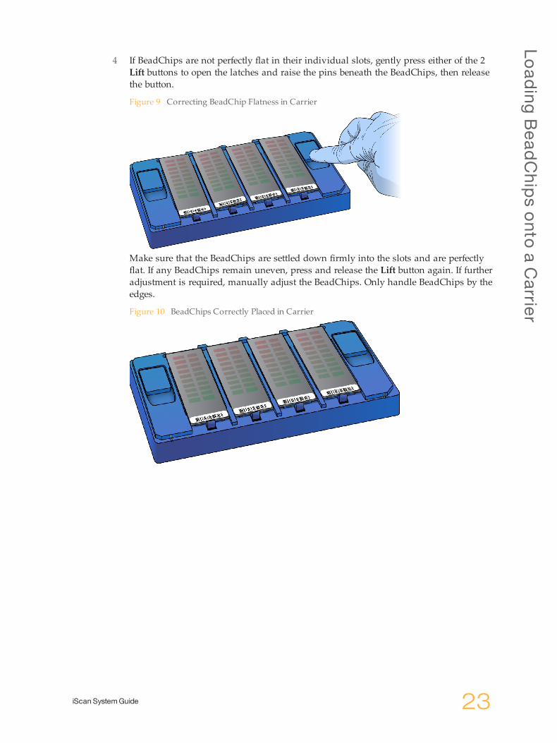
4 If BeadChips are not perfectly flat in their individual slots, gently press either of the 2Lift buttons to open the latches and raise the pins beneath the BeadChips, then releasethe button.
Figure 9 Correcting BeadChip Flatness in Carrier
Make sure that the BeadChips are settled down firmly into the slots and are perfectlyflat. If any BeadChips remain uneven, press and release the Lift button again. If furtheradjustment is required, manually adjust the BeadChips. Only handle BeadChips by theedges.
Figure 10 BeadChips Correctly Placed in Carrier

Load
ingBeadChips
24 Material # 20000396Document # 11313539 v01
LoadingaCarrier into the iScanReader
You can access the iScan Reader tray using either the iScan Control Software or theOpen/Close Tray button on the front of the iScan Reader. When loading a BeadChipcarrier, make sure to orient it properly in the iScan Reader tray.
NOTEYou can use the AutoLoader to automate the process of loading BeadChip carriers into theiScan Reader. For more information, see the AutoLoader2 User Guide or the AutoLoader 2.xUser Guide.
1 From the iScan Control Software Welcome screen, click Start. The iScanReader tray automatically opens.You can also open the iScan Reader tray using 1 of the following methods:} Click the menu button in the upper left corner of the screen and selectScanner | Open Tray.
} Press the Open/Close Tray button on the front of the iScan Reader. The Open/CloseTray button is located below the status LEDs.
Figure 11 Open/Close Tray Button
NOTEIf a BeadChip carrier is already in the iScan Reader tray, lift the carrier straight up andout of the tray to remove the carrier.
Load
ingaCarrier
intothe
iScan
Read
er
iScan SystemGuide 25
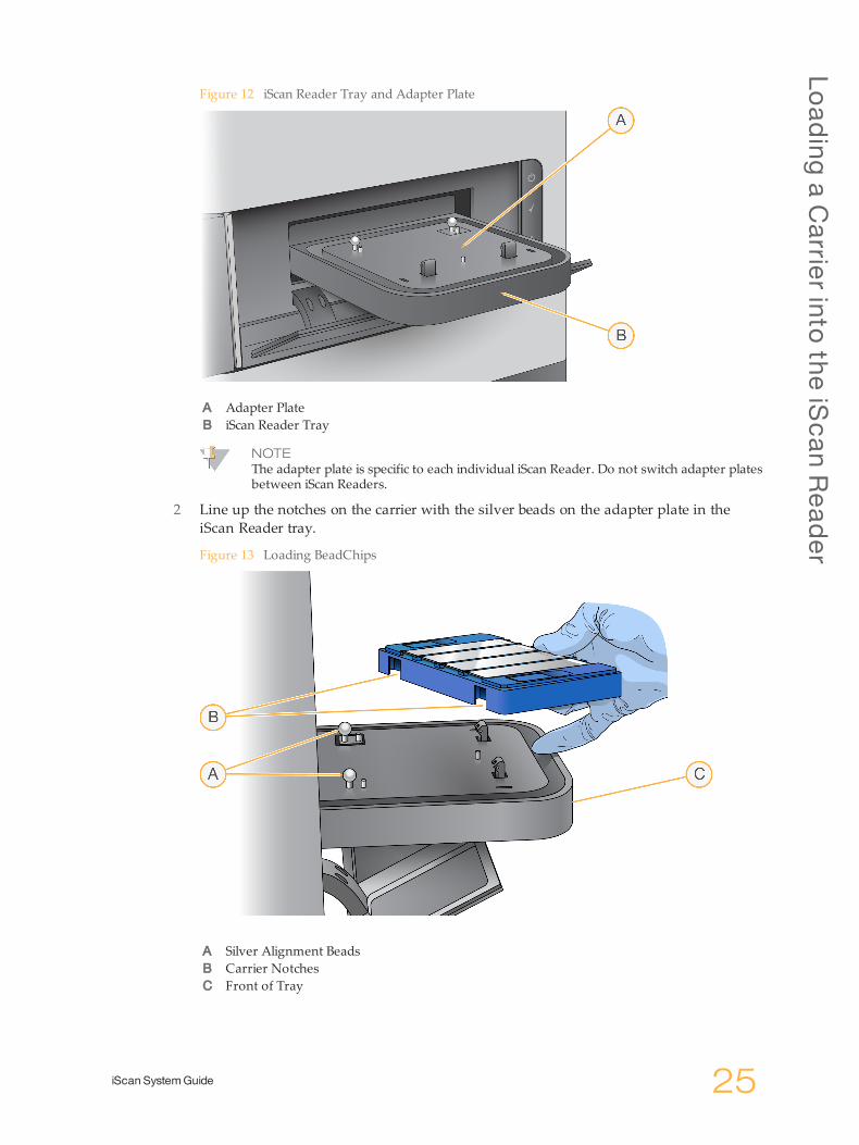
Figure 12 iScan Reader Tray and Adapter Plate
A Adapter PlateB iScan Reader Tray
NOTEThe adapter plate is specific to each individual iScan Reader. Do not switch adapter platesbetween iScan Readers.
2 Line up the notches on the carrier with the silver beads on the adapter plate in theiScan Reader tray.
Figure 13 Loading BeadChips
A Silver Alignment BeadsB Carrier NotchesC Front of Tray
Load
ingBeadChips
26 Material # 20000396Document # 11313539 v01
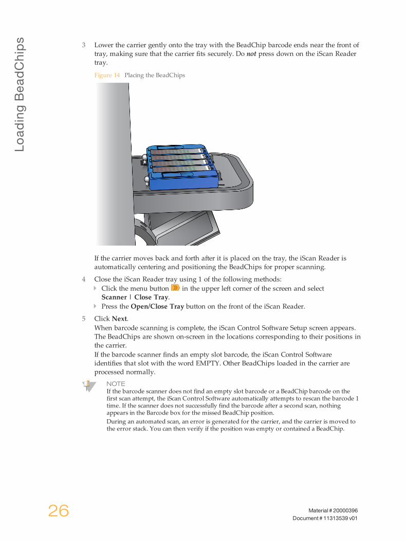
3 Lower the carrier gently onto the tray with the BeadChip barcode ends near the front oftray, making sure that the carrier fits securely. Do not press down on the iScan Readertray.
Figure 14 Placing the BeadChips
If the carrier moves back and forth after it is placed on the tray, the iScan Reader isautomatically centering and positioning the BeadChips for proper scanning.
4 Close the iScan Reader tray using 1 of the following methods:} Click the menu button in the upper left corner of the screen and selectScanner | Close Tray.
} Press the Open/Close Tray button on the front of the iScan Reader.
5 Click Next.When barcode scanning is complete, the iScan Control Software Setup screen appears.The BeadChips are shown on-screen in the locations corresponding to their positions inthe carrier.If the barcode scanner finds an empty slot barcode, the iScan Control Softwareidentifies that slot with the word EMPTY. Other BeadChips loaded in the carrier areprocessed normally.
NOTEIf the barcode scanner does not find an empty slot barcode or a BeadChip barcode on thefirst scan attempt, the iScan Control Software automatically attempts to rescan the barcode 1time. If the scanner does not successfully find the barcode after a second scan, nothingappears in the Barcode box for the missed BeadChip position.During an automated scan, an error is generated for the carrier, and the carrier is moved tothe error stack. You can then verify if the position was empty or contained a BeadChip.

Rescanning
Barco
des
iScan SystemGuide 27
RescanningBarcodes
To rescan barcodes in the Setup screen, click the menu button in the upper left corner ofthe screen, and then select Scanner | Scan Barcodes.You can manually enter the barcodes into the position that corresponds to the BeadChiplocation in the carrier. You can also manually delete barcodes to remove BeadChips from ascan.

28 Material # 20000396Document # 11313539 v01

Chapter4
iScan SystemGuide 29
Chapter 4 Configuring iScan Control Software
Configuring iScanControlSoftware
Introduction 30Omitting BeadChips from a Scan 31Changing Scan Settings 32
ConfiguringiScanControlS
oftware
30 Material # 20000396Document # 11313539 v01
Introduction
This chapter explains how to configure the iScan Control Software to perform a scan. If thedefault configuration values are already correct, simply click Scan to continue.
Omitting
Bead
Chip
sfro
maScan
iScan SystemGuide 31
OmittingBeadChips fromaScan
1 To remove a BeadChip from a scan, delete the BeadChip barcode number from theiScan Control Software Setup screen.
Omitting BeadChip Sections from a ScanYou can omit individual strips within a BeadChip from a scan.
NOTEAll sections of a BeadChip must be scanned when using LIMS. You cannot remove sectionsfrom the scan.
1 On the iScan Control Software Setup screen, the BeadChip preview area is on the leftside of the screen. At the top of the BeadChip preview area, select a BeadChip tochange the scan settings.
2 In the lower part of the BeadChip Preview area, click individual strips on the BeadChipto deselect them.Deselected strips change color from light blue to dark gray.
3 Click Scan.A confirmation dialog informs you that some sections are omitted from the scan, and ifany strip within a sample on the BeadChip is deselected, intensity data (*.idat files) arenot saved for that sample.

ConfiguringiScanControlS
oftware
32 Material # 20000396Document # 11313539 v01
ChangingScanSettings
If you want to use scan settings other than the default settings automatically selected basedon the BeadChip type, first create a custom scan settings file. Then associate the file withthe BeadChip on the iScan Control Software Setup screen. These processes are described inthe following sections.
Creating a Custom Scan Settings File1 Click the menu button in the upper left corner of the screen, and then select
Tools | Options.
2 In the Options dialog box, click the Scan Settings tab.
3 Highlight the scan setting that most closely resembles the custom scan setting that youwant to create, and then click Copy.The new scan setting appears at the bottom of the scan settings list.
4 With the new scan setting highlighted, edit 1 or more of the following settings.} Analysis:
} Enable Analysis—Set to True or False.} Include Outliers—Set to True or False.
} Misc (Miscellaneous):} Name—Enter a new name for the custom scan settings file.
} Output:} Export Bead Data—Set to True or False.} Export Bead Type Data—Set to True or False.} Image Format—Select JPG, PNG, or TIFF.JPG and PNG files are compressed image files. They are useful for reviewing thearray surface for defects that might have affected data quality. Intensity datacannot be extracted from JPG or PNG files.TIFF files are uncompressed image files. They consume more hard drive spacethan JPGs or PNGs, but intensity data can be extracted from TIFF files.
} Include XY in Bead Data—Set to True or False.} JPG Quality—If you selected JPG as the Image Format, set this value between 5and 100. The lower the number, the greater the image compression.
} Save Images—Set to True or False.Select False to conserve disk space or prevent large data files from traveling overyour network.
Other settings in this dialog box cannot be changed.
5 Click OK.
Applying a Custom Scan Setting to a BeadChip1 On the iScan Control Software Setup screen, click Settings at the end of the row of the
BeadChip whose scan settings you want to change.
2 In the Open Scan Setting File dialog, select the custom scan settings file you createdand click Open.
3 When prompted, click OK.Generating Normalized Data and Genotype Calls
Chang
ingScan
Setting
s
iScan SystemGuide 33
A BeadChip scan generates intensity data (*.idat) files. These files contain raw intensitydata values for every bead on the scanned image. For more information, see Log Files onpage 43.You can configure iScan Control Software to normalize the data in these files.Normalization transforms the range of intensity values for a BeadChip stripe to match atarget range, resulting in faster downstream processing times and optimized workflow.Normalized data and associated genotype calls are saved in genotype call (*.gtc) files.iScan Control Software includes an automated genotype calling feature, calledAutoConvert, which automatically converts *.idat files to *.gtc files during scanning, on aper-chip basis, for use in downstream analysis software such as Beeline or GenomeStudioSoftware.Configuring iScan Control Software to normalize your data requires you to set up amapping file that associates a type of BeadChip with its manifest and cluster files.
NOTEWhen running under LIMS, you cannot use the AutoConvert feature. Illumina LIMS uses itsown built-in automated genotype calling feature, called AutoCall. For more information onLIMS AutoCall, see the Illumina LIMS User Guide and the Illumina LIMS Project ManagerGuide.
Procedures1 Click theMenu button in the upper left corner of the screen, and then select
Tools | Options.
2 In the Options dialog box, click the AutoConvert tab.
3 Select the Enable AutoConvert checkbox.
4 Browse to an existing mapping file or click New to create a mapping file now.
5 [Optional] Edit the mapping file as follows:
a Click Edit Mapping File.b In the AutoConvert Mapping dialog, highlight the mapping you want to edit or
click New to create a mapping. For a new mapping, the row is populated withdefault entries.
c Click the PartNumber field in the right pane and enter or edit the product partnumber of the BeadChip. The product part number can be found on the BeadChippackaging.
d Click theManifestFilePath field, click the browse control , and navigate to andselect the bead pool manifest file (*.bpm).
e Click the ClusterFilePath field, click the browse control , and navigate to andselect the bead cluster file (*.egt).
f Click OK.
6 In the Options dialog, click OK.

ConfiguringiScanControlS
oftware
34 Material # 20000396Document # 11313539 v01
Specifying Input and Output PathsThe iScan System obtains processing file information from the input path. The output pathis the location where all files are saved upon scan completion.
NOTEWhen the iScan System is running under LIMS, you cannot change the input or output paths.These paths are designated by the LIMS project management software. Refer to the LIMSProject Manager Guide for instructions on how to change input and output path locations.
1 On the iScan Control Software Setup screen, next to the Input or Output Path, clickBrowse.
2 Navigate to the appropriate folders, and then click OK.} Input Path—The folder that contains subfolders for all the BeadChips that you arescanning. Make sure that the subfolders are named with each BeadChip barcodenumber and contains that BeadChip decode data (*.dmap) and *.sdf file.
} Output Path—The folder where you want iScan Control Software to save image files(*.jpg, *.png, or *.tif), bead location files (*.locs) when saving *.tifs, scan metrics (*.txt),and intensity data files (*.idat) for each BeadChip. Output for each BeadChip issaved in a subfolder named after the BeadChip barcode number.
Verifying DMAP File IntegrityIf *.dmap files transfer incorrectly to the network during downloading, file integrity canbecome compromised. The iScan Reader can be configured to check the integrity of *.dmapfiles at the start of each scan.
NOTEEnabling this feature increases the amount of time before the iScan Reader beginsperforming the scan.
1 Click the menu button in the upper left corner of the screen, and then selectTools | Options.
2 In the Options dialog box, click the General tab.
3 In the Processing section, select the Enable Corrupt DMAP Check checkbox, and thenclick OK.
Chapter5
iScan SystemGuide 35
Chapter 5 Scanning
Scanning
Introduction 36Starting a Scan 37Monitoring the Scan Progress 38Pausing, Resuming, and Stopping a Scan 39Completing a Scan 40

Scanning
36 Material # 20000396Document # 11313539 v01
Introduction
This section describes how to start, monitor, pause, stop, and complete scanning ofBeadChips.
NOTEBefore starting a scan, the lasers must stabilize. Make sure that the iScan Reader has been onfor at least 30 minutes before beginning a scan.
Starting
aScan
iScan SystemGuide 37
StartingaScan
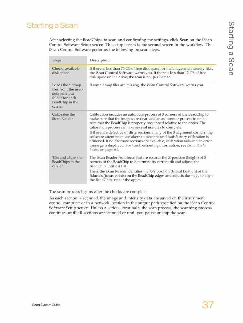
After selecting the BeadChips to scan and confirming the settings, click Scan on the iScanControl Software Setup screen. The setup screen is the second screen in the workflow. TheiScan Control Software performs the following prescan steps.
Steps Description
Checks availabledisk space
If there is less than 75 GB of free disk space for the image and intensity files,the iScan Control Software warns you. If there is less than 12 GB of freedisk space on the drive, the scan is not performed.
Loads the *.dmapfiles from the user-defined inputfolder for eachBeadChip in thecarrier
If any *.dmap files are missing, the iScan Control Software warns you.
Calibrates theiScan Reader
Calibration includes an autofocus process at 3 corners of the BeadChip tomake sure that the images are clear, and an autocenter process to makesure that the BeadChip is properly positioned relative to the optics. Thecalibration process can take several minutes to complete.If there are defective or dirty sections at any of the 3 alignment corners, thesoftware attempts to use alternate sections until satisfactory calibration isachieved. If no alternate sections are available, calibration fails and an errormessage is displayed. For troubleshooting information, see iScan ReaderIssues on page 64.
Tilts and aligns theBeadChips in thecarrier
The iScan Reader Autofocus feature records the Z-position (height) of 3corners of the BeadChip to determine its current tilt and adjusts theBeadChip until it is flat.Then, the iScan Reader identifies the X-Y position (lateral location) of thefiducials (focus points) on the BeadChip edges and adjusts the stage to alignthe BeadChips under the optics.
The scan process begins after the checks are complete.As each section is scanned, the image and intensity data are saved on the instrumentcontrol computer or in a network location in the output path specified on the iScan ControlSoftware Setup screen. Unless a serious error halts the scan process, the scanning processcontinues until all sections are scanned or until you pause or stop the scan.

Scanning
38 Material # 20000396Document # 11313539 v01
Monitoring the ScanProgress
As the iScan Reader scans, observe the following indicators to monitor scan progress:} Progress Indicator} Status bar} Information bar} Image Preview
Progress IndicatorThe Progress Indicator is on the left side of the screen and indicates the followinginformation about the scan progress:} Light Blue—Strip is queued to be scanned} Dark Gray—Strip will not be scanned} Orange—Strip is being scanned or registered} Green—Strip was successfully scanned and registered} Red—Scan and/or registration warning
Status BarThe Status Bar, located between the Image Preview and the Information Bar, shows thecurrent actions of the iScan Reader during scanning. Flashing LED lights indicate whichcomponents are in use for each action.
Information BarThe Information Bar is located across the bottom of the iScan Control Software Scan screen.The Information Bar summarizes the following information:} Scan Settings file} LIMS status} Input path} Output paths where intensity files and images are savedAn LED on the Information Bar also indicates the Initialization status:} Green—The iScan Reader initialized successfully.} Yellow—The iScan Reader has been conditionally initialized.} Red—The iScan Reader did not initialize.If the status LED is yellow or red, refer to Handling Errors on page 58.
Image PreviewThe Image Preview area fills most of the iScan Control Software Scan screen. The screendisplays the swath of the strip currently being scanned.
Pausing
,Resum
ing,and
Stopping
aScan
iScan SystemGuide 39
Pausing,Resuming, andStoppingaScan
During a scan, you can pause or stop the scan at any time.} To pause the scan, click Pause. The scan continues to the end of the current BeadChip
section, and then stops. The scan remains suspended until you click Resume.} To stop the scan, click Cancel. A confirmation message appears. If you confirm the
command, the scan process stops immediately and does not complete the currentsection. All completed sections are saved to disk.If you choose to rescan the BeadChip later, rescan all incomplete sections.

Scanning
40 Material # 20000396Document # 11313539 v01
CompletingaScan
When all the BeadChips are scanned, a completion message appears. Click OK to continueto the Review screen.When using LIMS, if all sections of a BeadChip are successfully scanned, the BeadChipdata are automatically submitted to LIMS. If any sections are not successfully scanned, thesection can be rescanned, the entire scan can be canceled, or the scan can be submitted toLIMS. After a chip is submitted to LIMS, unsuccessful areas cannot be rescanned.
NOTEIf 1 or more sections of a BeadChip did not successfully scan, click Rescan on the iScanControl Software Review screen to rescan the BeadChip. The iScan Control Software onlyrescans the sections that are not successfully scanned.
Chapter6
iScan SystemGuide 41
Chapter 6 Viewing Scan Results
ViewingScanResults
Introduction 42Log Files 43ScanMetrics 44Images 45Generated Files 49
ViewingScanResults
42 Material # 20000396Document # 11313539 v01
Introduction
This chapter describes how to review the results of your scan using:} Log Files} Scan Metrics} Images} Generated
LogFiles
iScan SystemGuide 43
LogFiles
During each run, the iScan Control Software creates a log file that lists each step in thescanning process. These logs are also copied into the data output folder for each BeadChipfor troubleshooting purposes.To view the current log file, perform the following steps.
1 Click theMenu button in the upper left corner of the screen and selectTools | Show Log.
2 Navigate to the folder named Logs in the iScan Control Software application folder toview the archived log files.
The log file size can reach up to 5 MB, and log files names are prefixed with, "iScanControl Software". The most current log file is named iScanControlSoftware.00.log. Whenthe most current log file reaches 5 MB in size, the software renames it toiScanControlSoftware.01.log. The software then creates a iScanControlSoftware.00.log fileand begins logging information in it.When this log file reaches 5 MB in size, the software renames iScanControlSoftware.01.logto iScanControlSoftware.02.log and renames iScanControlSoftware.00.log toiScanControlSoftware.01.log. As the most current log file reaches 5 MB in size, older logfiles are renamed in this manner up to iScanControlSoftware.20.log.When a iScanControlSoftware.20.log file exists and a new log file is created,iScanControlSoftware.20.log is deleted. The iScanControlSoftware.19.log replaces the fileand is renamed to iScanControlSoftware.20.log. iScanControlSoftware.00.log is always thecurrent log, and iScanControlSoftware.20.log is always the oldest.

ViewingScanResults
44 Material # 20000396Document # 11313539 v01
ScanMetrics
The scan metrics for each BeadChip appear in the Scan Metrics table at the top of theReview screen. This table allows you to review intensity values in the red and greenchannels, check the registration and focus metrics for each BeadChip stripe, and determinewhether intensity data was normalized for each scanned BeadChip section.} The focus metric ranges between 0 and 1. The higher the focus score, the sharper and
more well-defined the bead images are. A low focus score means that the bead imagesare not well-defined and bead colors bleed into each other.
} The registration value varies depending on the type of BeadChip, ranging between 0and 1 (multiple swaths per BeadChip) or between 0 and 2 (single swath per BeadChip).When the stripe registration is < 0.75, the stripe is flagged as potentially misregisteredand is colored red in the Scan Progress Indicator window. Misregistered sections canbe rescanned. For more information, seeMonitoring the Scan Progress on page 1.
} The AutoConvert column shows 1 of the following normalization metrics for eachscanned BeadChip section:} Converted—The *.idat file for that BeadChip section was converted to a *.gtc file. Theintensity data were normalized and genotype calls were generated. For moreinformation, see Log Files on page 43.
} N/A—The AutoConvert feature was not enabled for this scan. For more information,see Generating Normalized Data and Genotype Calls on page 32.
} Not Converted—The AutoConvert feature was enabled for this scan, but the *.idatfile for that BeadChip section was not converted to a *.gtc file. For troubleshootinginformation, see Log Files on page 43.
Scan metrics are also stored in 2 text files, Metrics.txt and [Barcode]_qc.txt, where [Barcode]represents the barcode number for a single BeadChip.
Figure 15 Contents of a [Barcode]_qc.txt Scan Metrics File

Imag
es
iScan SystemGuide 45
Images
This section describes how to review images of the scanned BeadChips in the iScan ControlSoftware before closing the software.After you click Done on the Review screen, you are returned to the Welcome screen and areno longer able to view the images in the iScan Control Software.
Selecting Images to View1 In the BeadChip carrier schematic at the top left side of the screen, select the BeadChip
whose images you want to review.
2 In the full-size image of the BeadChip, click a scanned stripe in the BeadChip.The highlighted section appears in the main part of the screen.Some BeadChip stripes are imaged using 2 or 3 smaller stripes, known as swaths.} 2 swaths—Swath 1 is shown on the top portion of the screen and is the image for thetop half of the imaged stripe. Swath 2 is shown on the bottom portion of the screenand is the image for the bottom half of the imaged stripe. The 2 swaths slightlyoverlap each other along their common edge to create the image for the entire stripe.
} 3 swaths—Shows the swaths in the top, middle, and bottom portions of the screen,with the swaths slightly overlapping each other along their common edges.
For BeadChips whose stripes are not scanned using 2 or 3 swaths, images appear onlyin the upper window.
3 If the images appear dark, click the Auto Contrast button to optimize the imagesettings and make both the green and red channels more visible.If both the red and green channels are enabled, select the Overlay Channels icon in theiScan Control Software workspace to generate a composite of both laser channels. Thiscomposite is a virtual file that does not require disk storage and cannot be saved.
Using the Toolbar Buttons to Adjust the ImageUse the icons on the Image toolbar for the following functions.
Icon Description
Auto Contrast—Resets the image contrast, brightness, pixels, and color ratioto default settings.
Auto Zoom—Adjusts the zoom on the image so that the full swath is visiblein the Image window.
Zoom In—Zooms in on the image in the Image window, so the image getslarger.
Zoom Out—Zooms out on the image in the Image window, so the imagegets smaller.
Copy to Clipboard—Copies the current view of the image in the Imagewindow to the clipboard so it can be pasted into another program.

ViewingScanResults
46 Material # 20000396Document # 11313539 v01
Icon Description
Overlay Cores—Allows you to confirm the registration of a specific Red orGreen image. When Overlay Cores is selected, the position of a particularbead microwell (core) as determined in the beadmap file (*.dmap) isrepresented as a blue circle over top of the image. When registration issuccessful, the intensity for individual beads lies inside the region covered bythe core and the overall pattern of cores is consistent with the pattern of beadintensities on the image: that is, the cores overlay on the individual beadswith a close fit. When registration fails, the cores do not overlay. In this case,rescan the BeadChip.
Show Green and Red Channels—Toggles to show only the green channel,only the red channel, or both channels in the Image window for the scannedsection.
Panning an ImageWhen you are viewing an image that is larger than the Image window, you can use thescroll bars on the Image window, or pan to show undisplayed areas. To pan, left-click andhold the image, and then drag until the desired section is shown.
Zooming In and OutZoom on an image using the following methods:} Use the zoom buttons on the Image toolbar.} Click the desired area of the image, and then use the scroll wheel on the mouse to
zoom in or out.
Using the Control Bars to Adjust the ImageThe image control icons ( and ) enable you to toggle which image adjustment controlbars are displayed in the main window. The Color control bar is available in both controlbar views.

Imag
es
iScan SystemGuide 47
Figure 16 Control Bars
A Pixel Intensities Control BarB Image Brightness Control BarC Image Contrast Control BarD Color Control Bars
Setting Pixel Intensities
1 Click the image control icon to show the Pixel Intensity control bar.
2 Pull the sliders together to sharpen the contrast for pixels within that range.} Pixels with a brightness above the top slider are set to full brightness.} Pixels whose brightness falls between the sliders are displayed with enhancedcontrast.
} Pixels with a brightness below the bottom slider are set to black.
Adjusting the Brightness1 Click the image control icon to show the Brightness control bar.
2 Move the Brightness slider up to increase image brightness or down to decrease imagebrightness.
Adjusting the Contrast1 Click the image control icon to show the Contrast control bar.
2 Move the Contrast slider up to increase the image contrast or down to decrease thecontrast.
ViewingScanResults
48 Material # 20000396Document # 11313539 v01
Adjusting the Color1 Move the slider on the Color control bar up to adjust the color toward red. Move the
slider down to adjust the color toward green.

Generated
Files
iScan SystemGuide 49
GeneratedFiles
After images are scanned, they are registered and intensities are extracted for every beadtype. If the AutoConvert feature was enabled, iScan Control Software normalizes theintensity data and generates genotype calls.} Registration—Registration identifies beads by correlating their locations on the scanned
image with information in the bead map (*.dmap) file.} Intensity Data—The intensity extraction process determines the intensity values for
every bead on the image. Statistics are generated for every bead type based on theintensities of the replicate beads for that type. Extracted information is saved inintensity data (*.idat) files.Intensity data (*.idat) files are only created for samples that have all their stripesscanned. These files are not created when scanning individual stripes within a samplesection on a BeadChip.
NOTEAn *.idat file is generated when the registration data for all stripes is present for agiven sample. If all stripes are scanned, regardless of their results for registration orother metrics, an *.idat file is always generated. If a hardware error occurs whereby atleast one stripe in the sample is not scanned, then no *.idat file is generated for thesample.
} Normalized Data—If the AutoConvert feature was enabled for the scan, iScan ControlSoftware normalizes the data in your *.idat files and generates genotype calls from thenormalized data. The normalized data and genotype calls are saved in genotype call(*.gtc) files. For more information, see Generating Normalized Data and Genotype Calls onpage 32.The *.idat and (if applicable) *.gtc files are saved on the instrument control computer ornetwork under the BeadChip ID (barcode identifier) subfolder, in the output path folder.
} Effective.cfg—This file is created at the start of a scan and contains all the scannerconfiguration information for the current scan. It is also placed in the BeadChip IDfolder in the output path.
Scan or Registration FailureRegistration and extraction are critical to obtaining results from your experiments.If 1 or more stripes fail scanning or registration in a sample section, the stripes can berescanned from the iScan Control Software Review screen using the Rescan button. Uponrescan, new intensity data files are generated. When failed sections on a BeadChip areimmediately rescanned within the current scan session, new image files are created onlyfor the sections that are scanned. When an entire BeadChip is rescanned, all image files arerecreated.If you click Done on the Review screen without rescanning the failed sections, the *.idatfiles are created without data from the failed section, which could reduce assayperformance or results. Rescan the entire sample section during a future session to generatecomplete *.idat files.When an entire BeadChip or sections of a BeadChip are rescanned during another session,new metrics and *.idat/*.gtc and *.qc files are created with each rescan and overwriteexisting files. To prevent files from being overwritten, save the rescan data in anotheroutput data folder.
ViewingScanResults
50 Material # 20000396Document # 11313539 v01
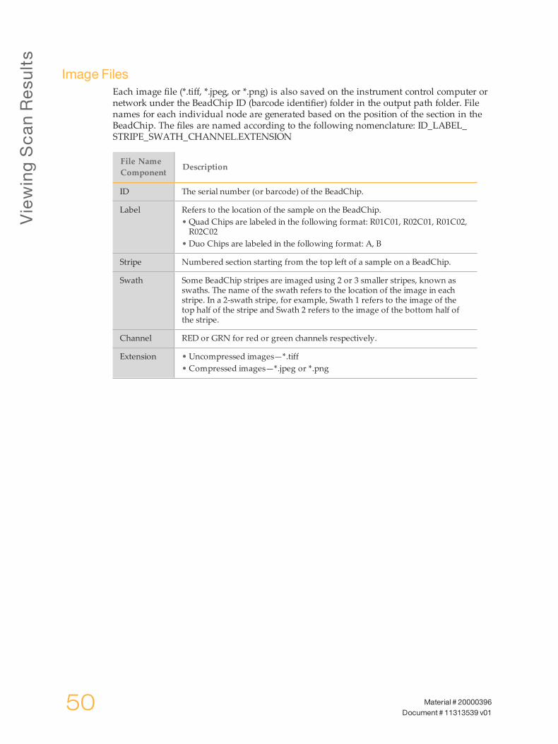
Image FilesEach image file (*.tiff, *.jpeg, or *.png) is also saved on the instrument control computer ornetwork under the BeadChip ID (barcode identifier) folder in the output path folder. Filenames for each individual node are generated based on the position of the section in theBeadChip. The files are named according to the following nomenclature: ID_LABEL_STRIPE_SWATH_CHANNEL.EXTENSION
File NameComponent Description
ID The serial number (or barcode) of the BeadChip.
Label Refers to the location of the sample on the BeadChip.• Quad Chips are labeled in the following format: R01C01, R02C01, R01C02,R02C02
• Duo Chips are labeled in the following format: A, B
Stripe Numbered section starting from the top left of a sample on a BeadChip.
Swath Some BeadChip stripes are imaged using 2 or 3 smaller stripes, known asswaths. The name of the swath refers to the location of the image in eachstripe. In a 2-swath stripe, for example, Swath 1 refers to the image of thetop half of the stripe and Swath 2 refers to the image of the bottom half ofthe stripe.
Channel RED or GRN for red or green channels respectively.
Extension • Uncompressed images—*.tiff• Compressed images—*.jpeg or *.png
Chapter7
iScan SystemGuide 51
Chapter 7 Shutting Down, Maintenance, and Service
ShuttingDown,Maintenance,andService
Introduction 52Shutting Down the iScan System 53Maintenance 54Service 55

ShuttingDown,Maintenance,and
Service
52 Material # 20000396Document # 11313539 v01
Introduction
This chapter describes instructions for shutting down the iScan System, along withmaintenance, and service recommendations.

Shutting
Downthe
iScan
System
iScan SystemGuide 53
ShuttingDown the iScanSystem
Perform the steps to shutting down the iScan System in the following order.
1 Eject BeadChips.
a Open the iScan Reader tray.b To remove the carrier, lift it straight up and out of the tray.
2 Close the iScan Control Software.
a Click the menu button in the upper left corner of the screen.b Select Exit.
3 From the Windows Start menu on the iScan System computer, select Shut Down.
4 Press the Power switch on the back panel of the iScan Reader.
NOTEWait at least 2 minutes before turning on the iScan Reader again.
Ejecting BeadChips1 Open the iScan Reader tray.
2 To remove the carrier, lift it straight up and out of the tray.
Closing the iScan Control Software1 Click the menu button in the upper left corner of the screen.
2 Select Exit.
Shutting Down the iScan System Computer1 From the Windows Start menu, select Shut Down.
Shutting Down the iScan Reader1 Press the Power switch on the back panel of the iScan Reader.
NOTEWait at least 2 minutes before turning on the iScan Reader again.
ShuttingDown,Maintenance,and
Service
54 Material # 20000396Document # 11313539 v01
Maintenance
Cleaning the iScan SystemTo clean the equipment, dampen a cloth with water and a mild detergent and wipe downall external surfaces. There are no internal surfaces that require cleaning.
Maintaining and Calibrating the iScan SystemContact Illumina Technical Support to schedule yearly maintenance and calibration.
Service
iScan SystemGuide 55
Service
CAUTIONThere are no user-serviceable items inside the equipment. Refer any service requests toqualified Illumina service personnel.

56 Material # 20000396Document # 11313539 v01
Chapter8
iScan SystemGuide 57
Appendix 8 Troubleshooting
Troubleshooting
Handling Errors 58Issue Types 59Registration Issues 60Auto-Alignment Issues 62iScan Reader Issues 64Image Quality Issues 67iScan Control Software Display Issues 69

Troub
leshooting
58 Material # 20000396Document # 11313539 v01
HandlingErrors
The iScan Control Software records system errors to a log file as they occur. The logprovides a record of system events that you can send to Illumina Technical Support forevaluation. If an error occurs, you can view error details in the error message box and thelog file.This chapter provides information about how to manage iScan System errors, including:} Viewing error details} Reporting errors
Viewing Error Details as they OccurIf an error occurs when using the iScan System, an error message box is displayed. To takea screen capture of the error message, press the Alt and Print Screen keys simultaneously.This command takes a picture of the PC screen. Open a Word or WordPad document, pastethe image, and save the document. Send the word document to Illumina technical support.
Reporting ErrorsIf an error occurs, send the error details to Illumina Technical Support.
1 Email a description of the error to Illumina Technical Support. See Technical Assistanceon page 73. Attach a screen capture of the error when possible.
2 Attach the most recent event log to the email. The most recent event log is named iScanControl Software.00.log.If you are using the AutoLoader (AutoLoader2 or AutoLoader 2.x) and the system wasrunning in AutoLoader mode at the time of the error, attach the AutoLoader log file.To determine the location of the event log, perform the following steps.
a From the main Windows screen, click Start, then right-click iScan Control Software.b Click Properties. The location of the event log is displayed in the Start in box of the
iScan Control Software Properties dialog box.
For more information about log files, see Log Files on page 43. For more informationabout the AutoLoader, see the AutoLoader2 User Guide or the AutoLoader 2.x User Guide.
IssueTypes
iScan SystemGuide 59
Issue Types
Issues that can appear when using the iScan System fall into the following generalcategories:} Registration issues} Autoalignment issues} iScan Reader issues} Image quality issues} iScan Control Software display issuesThe following sections describe these types of issues, with solutions for each.
Troub
leshooting
60 Material # 20000396Document # 11313539 v01
Registration Issues
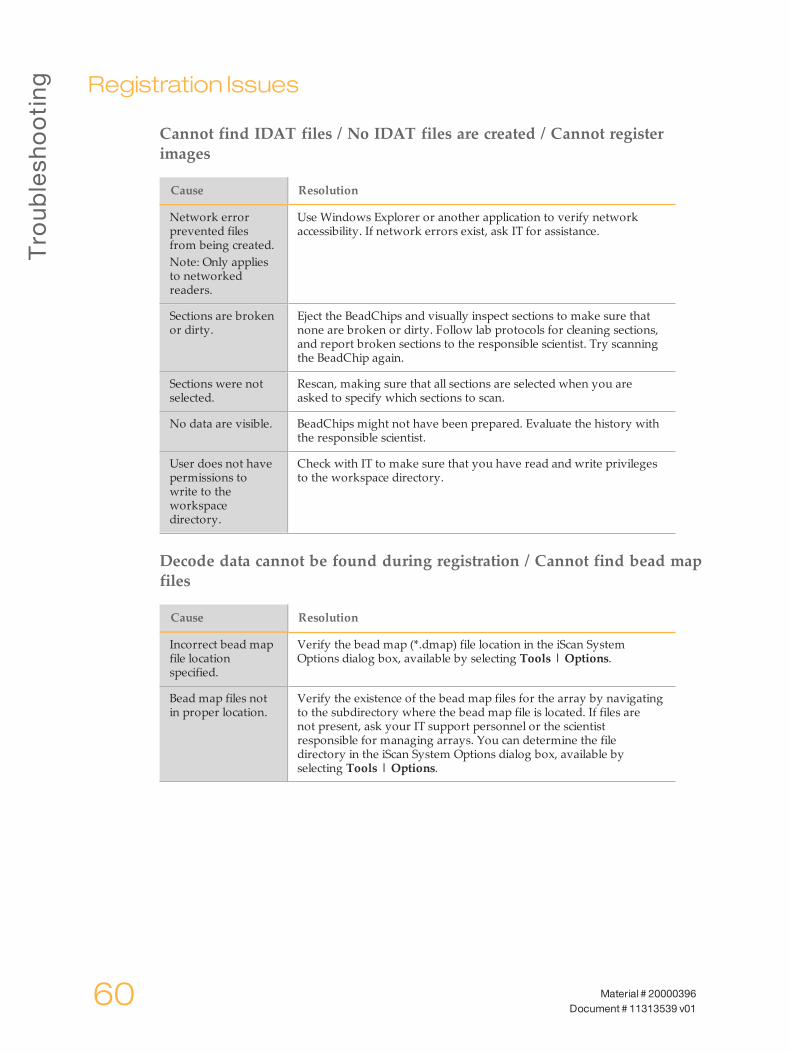
Cannot find IDAT files / No IDAT files are created / Cannot registerimages
Cause Resolution
Network errorprevented filesfrom being created.Note: Only appliesto networkedreaders.
Use Windows Explorer or another application to verify networkaccessibility. If network errors exist, ask IT for assistance.
Sections are brokenor dirty.
Eject the BeadChips and visually inspect sections to make sure thatnone are broken or dirty. Follow lab protocols for cleaning sections,and report broken sections to the responsible scientist. Try scanningthe BeadChip again.
Sections were notselected.
Rescan, making sure that all sections are selected when you areasked to specify which sections to scan.
No data are visible. BeadChips might not have been prepared. Evaluate the history withthe responsible scientist.
User does not havepermissions towrite to theworkspacedirectory.
Check with IT to make sure that you have read and write privilegesto the workspace directory.
Decode data cannot be found during registration / Cannot find bead mapfiles
Cause Resolution
Incorrect bead mapfile locationspecified.
Verify the bead map (*.dmap) file location in the iScan SystemOptions dialog box, available by selecting Tools | Options.
Bead map files notin proper location.
Verify the existence of the bead map files for the array by navigatingto the subdirectory where the bead map file is located. If files arenot present, ask your IT support personnel or the scientistresponsible for managing arrays. You can determine the filedirectory in the iScan System Options dialog box, available byselecting Tools | Options.
Reg
istrationIssues
iScan SystemGuide 61
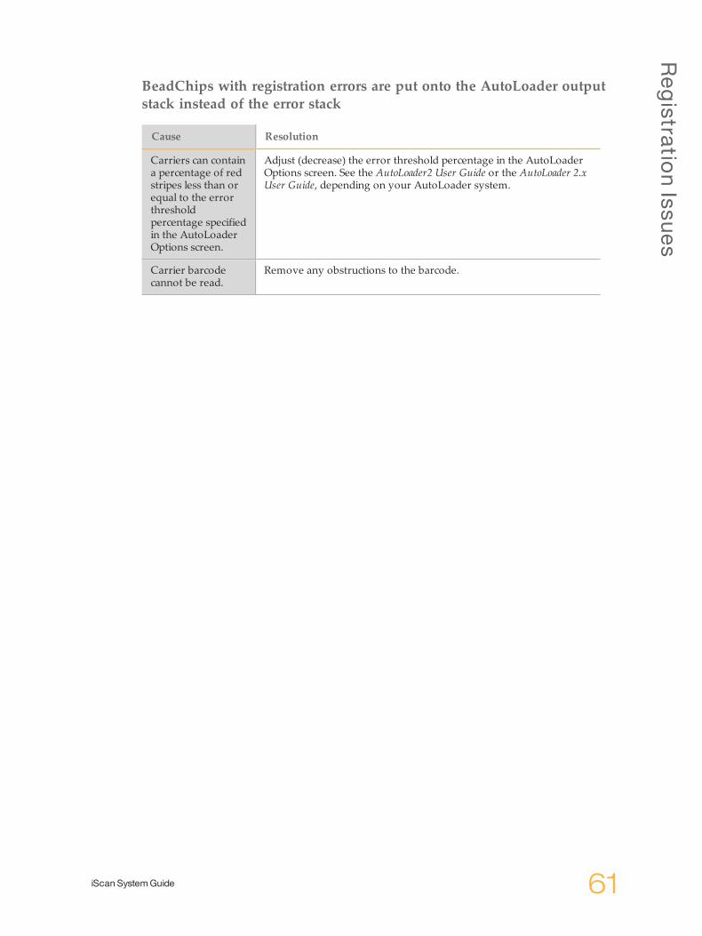
BeadChips with registration errors are put onto the AutoLoader outputstack instead of the error stack
Cause Resolution
Carriers can containa percentage of redstripes less than orequal to the errorthresholdpercentage specifiedin the AutoLoaderOptions screen.
Adjust (decrease) the error threshold percentage in the AutoLoaderOptions screen. See the AutoLoader2 User Guide or the AutoLoader 2.xUser Guide, depending on your AutoLoader system.
Carrier barcodecannot be read.
Remove any obstructions to the barcode.
Troub
leshooting
62 Material # 20000396Document # 11313539 v01
Auto-Alignment Issues
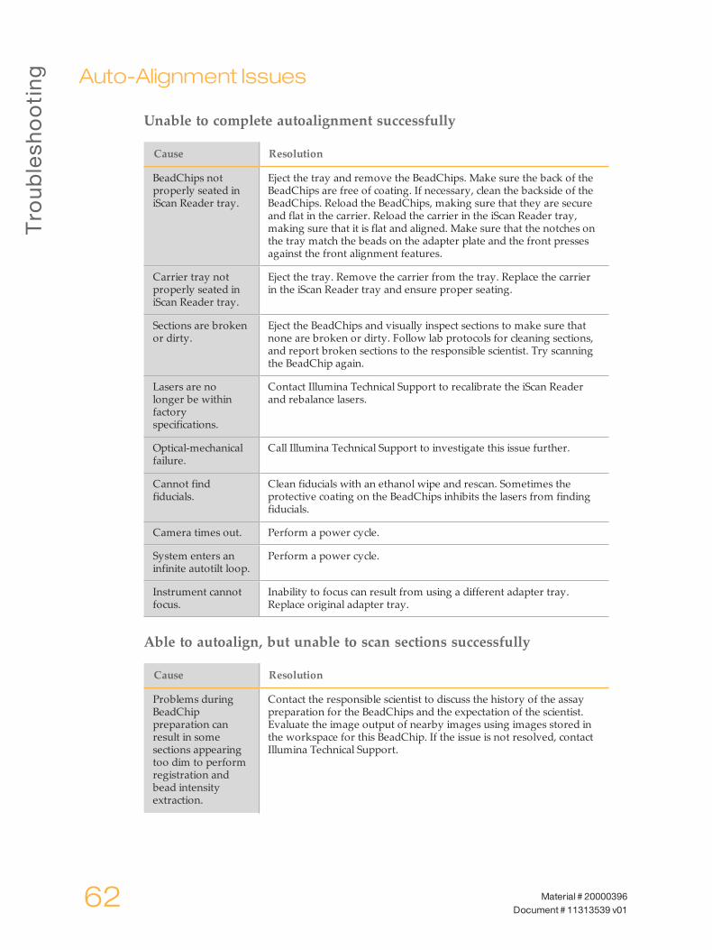
Unable to complete autoalignment successfully
Cause Resolution
BeadChips notproperly seated iniScan Reader tray.
Eject the tray and remove the BeadChips. Make sure the back of theBeadChips are free of coating. If necessary, clean the backside of theBeadChips. Reload the BeadChips, making sure that they are secureand flat in the carrier. Reload the carrier in the iScan Reader tray,making sure that it is flat and aligned. Make sure that the notches onthe tray match the beads on the adapter plate and the front pressesagainst the front alignment features.
Carrier tray notproperly seated iniScan Reader tray.
Eject the tray. Remove the carrier from the tray. Replace the carrierin the iScan Reader tray and ensure proper seating.
Sections are brokenor dirty.
Eject the BeadChips and visually inspect sections to make sure thatnone are broken or dirty. Follow lab protocols for cleaning sections,and report broken sections to the responsible scientist. Try scanningthe BeadChip again.
Lasers are nolonger be withinfactoryspecifications.
Contact Illumina Technical Support to recalibrate the iScan Readerand rebalance lasers.
Optical-mechanicalfailure.
Call Illumina Technical Support to investigate this issue further.
Cannot findfiducials.
Clean fiducials with an ethanol wipe and rescan. Sometimes theprotective coating on the BeadChips inhibits the lasers from findingfiducials.
Camera times out. Perform a power cycle.
System enters aninfinite autotilt loop.
Perform a power cycle.
Instrument cannotfocus.
Inability to focus can result from using a different adapter tray.Replace original adapter tray.
Able to autoalign, but unable to scan sections successfully
Cause Resolution
Problems duringBeadChippreparation canresult in somesections appearingtoo dim to performregistration andbead intensityextraction.
Contact the responsible scientist to discuss the history of the assaypreparation for the BeadChips and the expectation of the scientist.Evaluate the image output of nearby images using images stored inthe workspace for this BeadChip. If the issue is not resolved, contactIllumina Technical Support.
Auto
-Alignm
entIssues
iScan SystemGuide 63
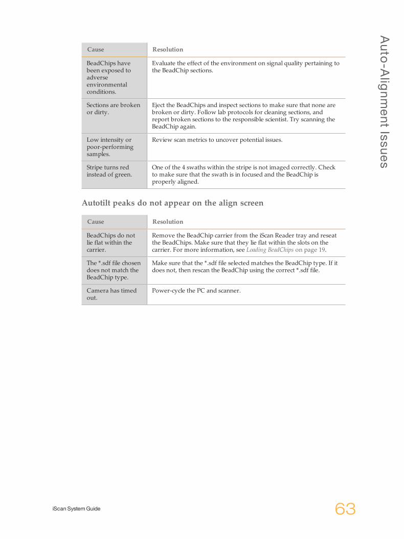
Cause Resolution
BeadChips havebeen exposed toadverseenvironmentalconditions.
Evaluate the effect of the environment on signal quality pertaining tothe BeadChip sections.
Sections are brokenor dirty.
Eject the BeadChips and inspect sections to make sure that none arebroken or dirty. Follow lab protocols for cleaning sections, andreport broken sections to the responsible scientist. Try scanning theBeadChip again.
Low intensity orpoor-performingsamples.
Review scan metrics to uncover potential issues.
Stripe turns redinstead of green.
One of the 4 swaths within the stripe is not imaged correctly. Checkto make sure that the swath is in focused and the BeadChip isproperly aligned.
Autotilt peaks do not appear on the align screen
Cause Resolution
BeadChips do notlie flat within thecarrier.
Remove the BeadChip carrier from the iScan Reader tray and reseatthe BeadChips. Make sure that they lie flat within the slots on thecarrier. For more information, see Loading BeadChips on page 19.
The *.sdf file chosendoes not match theBeadChip type.
Make sure that the *.sdf file selected matches the BeadChip type. If itdoes not, then rescan the BeadChip using the correct *.sdf file.
Camera has timedout.
Power-cycle the PC and scanner.
Troub
leshooting
64 Material # 20000396Document # 11313539 v01
iScanReader Issues
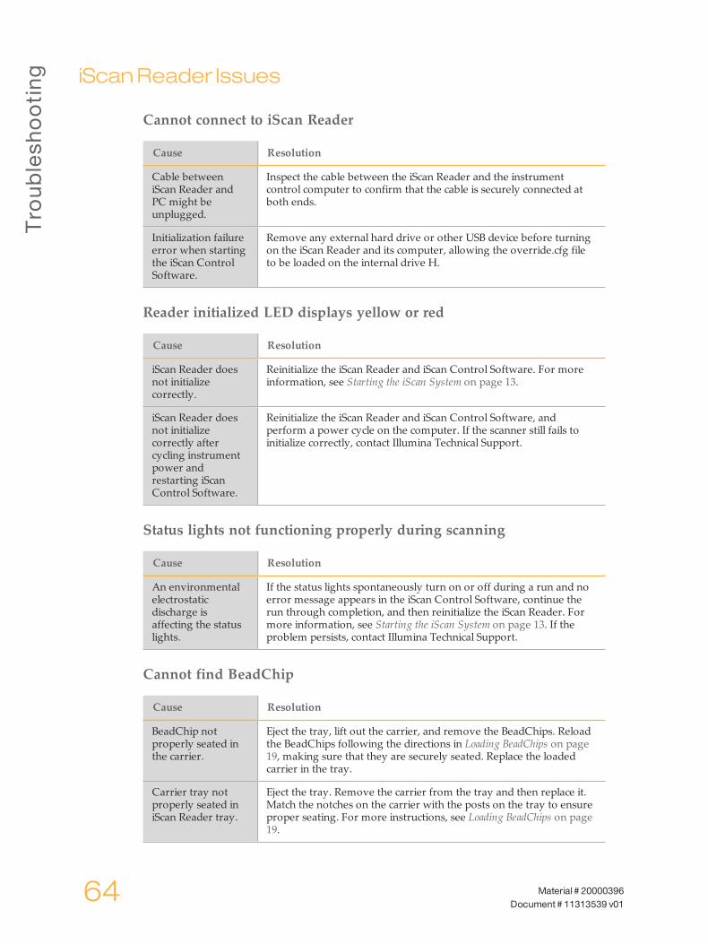
Cannot connect to iScan Reader
Cause Resolution
Cable betweeniScan Reader andPC might beunplugged.
Inspect the cable between the iScan Reader and the instrumentcontrol computer to confirm that the cable is securely connected atboth ends.
Initialization failureerror when startingthe iScan ControlSoftware.
Remove any external hard drive or other USB device before turningon the iScan Reader and its computer, allowing the override.cfg fileto be loaded on the internal drive H.
Reader initialized LED displays yellow or red
Cause Resolution
iScan Reader doesnot initializecorrectly.
Reinitialize the iScan Reader and iScan Control Software. For moreinformation, see Starting the iScan System on page 13.
iScan Reader doesnot initializecorrectly aftercycling instrumentpower andrestarting iScanControl Software.
Reinitialize the iScan Reader and iScan Control Software, andperform a power cycle on the computer. If the scanner still fails toinitialize correctly, contact Illumina Technical Support.
Status lights not functioning properly during scanning
Cause Resolution
An environmentalelectrostaticdischarge isaffecting the statuslights.
If the status lights spontaneously turn on or off during a run and noerror message appears in the iScan Control Software, continue therun through completion, and then reinitialize the iScan Reader. Formore information, see Starting the iScan System on page 13. If theproblem persists, contact Illumina Technical Support.
Cannot find BeadChip
Cause Resolution
BeadChip notproperly seated inthe carrier.
Eject the tray, lift out the carrier, and remove the BeadChips. Reloadthe BeadChips following the directions in Loading BeadChips on page19, making sure that they are securely seated. Replace the loadedcarrier in the tray.
Carrier tray notproperly seated iniScan Reader tray.
Eject the tray. Remove the carrier from the tray and then replace it.Match the notches on the carrier with the posts on the tray to ensureproper seating. For more instructions, see Loading BeadChips on page19.

iScan
Read
erIssues
iScan SystemGuide 65
Fault light illuminates
Cause Resolution
iScan Readerrequiresreinitialization.
Click theMenu button in the upper left corner of the iScan ControlSoftware screen, and then select Scanner | Initialize.
iScan Control Software (ICS) displays FPGA timeout errors
Cause Resolution
Problems withemission filter slide,excitation filterwheel, tilt motor,tray switch, and/orlaser safety switch.
Take a screen capture of the error and save it. Close the iScanControl Software and power cycle the scanner to clear the FPGA.Restart the iScan Control Software to see if the error repeats. If theerror occurs again, contact Illumina Technical Support and schedule afield service call.
iScan Reader reports a mechanical error, and does not scan
Cause Resolution
If the iScan Readerdetects a possiblemechanical error, itimmediatelydisables all motorsfor safety. Usererror can also causea mechanical error.
Visually inspect the iScan Reader internally and around the carriertray where the BeadChips are loaded. If there is an obvious physicalproblem, call Illumina Technical Support to guide you through safelyfreeing the BeadChip.If there is no apparent physical problem, then either reinitialize orshut down and power cycle the iScan Reader. To reinitialize the iScanReader, click theMenu button in the upper left corner of the iScanControl Software screen, and then select Scanner | Initialize.
iScan Control Software displays x-motor, y-motor, or z-motor errors
Cause Resolution
Amotor erroroccurred in an x-,y-, or z-stagemotor. Sometimesan error occurs forone motor becauseof an initial error inanother motor.
Take a screen capture of the error and save it. If the error caused thescan to stop, close the iScan Control Software and power cycle thescanner to rehome the motors. Restart the iScan Control Software tosee if the error repeats. If the error occurs again, contact IlluminaTechnical Support and schedule a field service call.
BeadChip does notlie flat or isimproperly seatedwithin a carrier.
Eject the BeadChip carrier and examine how the carrier is seated inthe iScan Reader adapter tray. Try reseating the BeadChips withinthe carrier and restarting the scan.

Troub
leshooting
66 Material # 20000396Document # 11313539 v01
The internal barcode scanner does not recognize BeadChip barcodes
Cause Resolution
Barcode quality ispoor.
Eject the BeadChip carrier and examine the barcodes to make surethat they are present and of good print quality. Reload the carrierand rescan. If the barcode still fails to be read, try to enter thebarcode number manually into the correct position using the iScanControl Software.

Imag
eQuality
Issues
iScan SystemGuide 67
ImageQuality Issues
The iScan Reader is producing low intensity images
Cause Resolution
Low assay signal. Review the history of assay preparation with the responsiblescientist. Evaluate the length of time after preparation, concentrationof signal source due to evaporation, and adverse environmentalconditions including humidity, temperature, and amount of directsunlight.
Bad focus. Stop the scan, eject the BeadChips, and check the sections for foreignmatter that can affect focus. Make sure that the BeadChips are flat inthe carrier and that their back sides are clean.
Broken section. If a section is broken, then it cannot produce high-quality data.However, the rest of the BeadChip is not affected.
Contrast bars arenot set for optimalviewing of images.
Select the Auto Contrast checkbox. If images are still not optimal,readjust the contrast sliders. For more information, see Viewing ScanResults on page 41.
Images are presentbut intensity dataare low, eventhough registrationis successful.
Data are acceptable and uncompromised.
Displayed images appear too white with no detail
Cause Resolution
Contrast is not setfor optimal viewingof images.
Select the Auto Contrast checkbox. If images are still not optimal,readjust the contrast sliders. For more information, see Viewing ScanResults on page 41.
Section appears slightly compressed and distorted
Cause Resolution
Monitor is notadjusted fordisplayedresolution.
The appearance of the section has no effect on your data. Use thehorizontal and vertical size controls of your monitor to manipulatethe appearance of a section so it appears regular (all sides are thesame length).Make sure that your video driver resolution is set to 1280 x 1024.
System displays “Cannot initialize camera frame grabber” error
Cause Resolution
Camera cable onback of scanner isloose.
Tighten connection, then restart the scanner and restart the iScanControl Software. Power cycle the scanner and/or PC as many timesas necessary until the frame grabber is able to initialize successfully.
Troub
leshooting
68 Material # 20000396Document # 11313539 v01
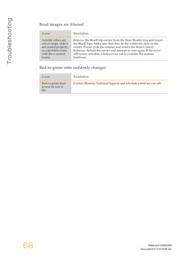
Bead images are blurred
Cause Resolution
Autotilt values areout of range, slide isnot seated properly,or a problem existswith the z-controlboard.
Remove the BeadChip carrier from the iScan Reader tray and reseatthe BeadChips. Make sure that they lie flat within the slots on thecarrier. Power cycle the scanner and restart the iScan ControlSoftware. Reload the carrier and attempt to scan again. If the errorstill occurs, schedule a field service call to examine the scannerhardware.
Red-to-green ratio suddenly changes
Cause Resolution
Red or green laseris near its end oflife.
Contact Illumina Technical Support and schedule a field service call.

iScan
Contro
lSoftw
areDisp
layIssues
iScan SystemGuide 69
iScanControl SoftwareDisplay Issues
Buttons are inaccessible / Text or icons distorted or truncated
Cause Resolution
Monitor resolutiontoo low.
Set monitor resolution to a minimum of 1280 x 1024, and 16 bit color.
Computer displays blue screen
Cause Resolution
Loose cableconnection betweencamera and framegrabber card.
Check to see if the camera link cable leading to the frame grabbercard has become loose. If the cable seems tight, reseat the framegrabber card.
Large number ofports have beeninstalled on thecomputer.
Contact Illumina Technical Support to schedule a field service call.

70 Material # 20000396Document # 11313539 v01

Index
iScan SystemGuide 71
Index
Aauto contrast 45auto zoom 45AutoConvert 33
Bbarcode scanner 4BeadChip carrier 7components 7
BeadChipsloading 20scanning 36
brightness, adjusting 47
Ccleaning 54color, adjusting 48componentsBeadChip carrier 7computer 5Reader tray 5status lights 5
computer 5hard drive configuration 5powering up 15
contrast, adjusting 47Control Softwareauto contrast 45auto zoom 45copy to clipboard 45icon on desktop 16image control icons 46image toolbar 45information bar 38Menu button 10overlay cores 46progress indicator 38show green and red channels 46status bar 38zoom in 45zoom out 45
copy to clipboard 45customer support 73
Ddmap files 49documentation 3, 73
Eeffective.cfg file 49errorshandling 58reporting 58
Ggenerated filesdmap 49idat 49images 50
genotype call files 33
Hhelpdocumentation 3
help, technical 73
Iidat files 49Image Preview area 38image toolbar 45imagesadjusting 45brightness, adjusting 47color, adjusting 48contrast, adjusting 47panning 46pixel intensity, setting 47reviewing 45
information bar 38iScan Control Softwarecustom scan settings file 32
iScan Systemprocess overview 11using LIMS with 17
LLIMSenabling and disabling 17using with the iScan System 17
loading BeadChips 20log files 43
MMenu button 10metrics 44monitor scan 38
Oonline training 3overlay cores 46
Ppower upReader 15System computer 15
progress indicator 38

Index
72 Material # 20000396Document # 11313539 v01
RReaderpowering up 15reinitializing 16
Reader tray 5red stripes 61
SscanBeadChips 36completing 40custom settings 32generated files 49log files 43metrics 44monitoring 38pausing 39progress 38resuming 39reviewing images 45starting 37stopping 39
show green and red channels 46status bar 38status lights 5stripesred 61
Systemcomputer 5computer, powering up 15
Ttechnical assistance 73
Zzoom in 45zoom out 45
TechnicalA
ssistance
iScan SystemGuide 73
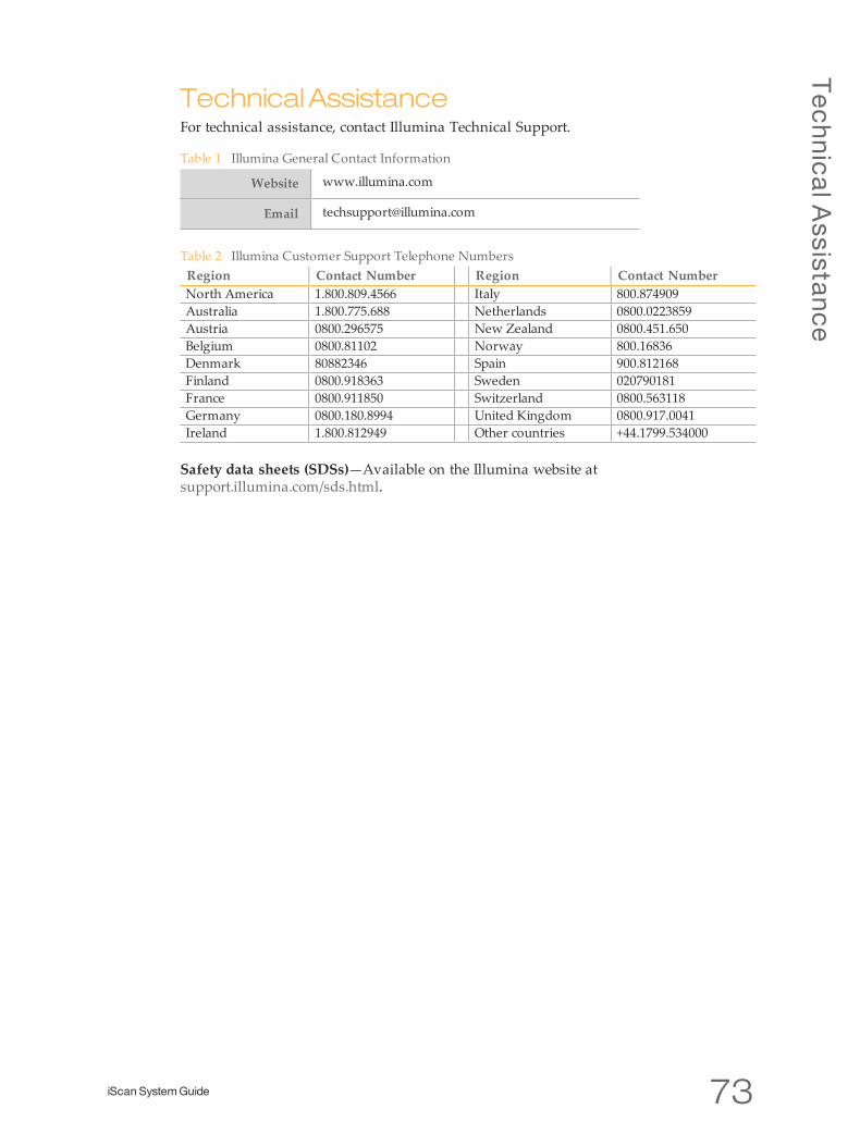
TechnicalAssistanceFor technical assistance, contact Illumina Technical Support.
Website www.illumina.com
Email [email protected]
Table 1 Illumina General Contact Information
Region Contact Number Region Contact NumberNorth America 1.800.809.4566 Italy 800.874909Australia 1.800.775.688 Netherlands 0800.0223859Austria 0800.296575 New Zealand 0800.451.650Belgium 0800.81102 Norway 800.16836Denmark 80882346 Spain 900.812168Finland 0800.918363 Sweden 020790181France 0800.911850 Switzerland 0800.563118Germany 0800.180.8994 United Kingdom 0800.917.0041Ireland 1.800.812949 Other countries +44.1799.534000
Table 2 Illumina Customer Support Telephone Numbers
Safety data sheets (SDSs)—Available on the Illumina website atsupport.illumina.com/sds.html.

Illumina5200 Illumina WaySan Diego, California 92122 U.S.A.+1.800.809.ILMN (4566)+1.858.202.4566 (outside North America)[email protected]