is400 series - amazon web services
TRANSCRIPT

M_I
S400
ser
ies_
EN_A
- La
st u
pdat
ed: 0
7/20
17 -
Tran
slat
ion
of th
e Fr
ench
orig
inal
doc
umen
t
OPERATING AND MAINTENANCE MANUAL
IS400 seriesIS400 / IS400 VOLUME
Electronic engraving machine

Table of contents
M_IS400 series_EN_A 2
A. Foreword ...................................................................................................................................................5
1. Appreciation ...........................................................................................................................................52. Information .............................................................................................................................................5
B. Legal notices ............................................................................................................................................6
C. Regulation observance ............................................................................................................................7
D. Introduction ..............................................................................................................................................8
1. Presentation ...........................................................................................................................................82. Identificationofthemarkingequipment..................................................................................................8
E. Unpacking .................................................................................................................................................9
1. Unpacking ..............................................................................................................................................92. Packagecontents .................................................................................................................................10
� IS400 VOLUME ..................................................................................................................................10
� IS400 ..................................................................................................................................................11
3. Toolbox: content ...................................................................................................................................11
F. Safety .......................................................................................................................................................12
1. Recommendations and safety ..............................................................................................................12 � Personnel safety ................................................................................................................................12
� Handling the machine ........................................................................................................................13
� Wearing safety glasses ......................................................................................................................13
2. Requiredsafetylabels ..........................................................................................................................14
G. Description of the machine ...................................................................................................................15
1. Front view of the machine ....................................................................................................................15 � IS400 ..................................................................................................................................................15
� IS400 VOLUME ..................................................................................................................................16
� Vice ....................................................................................................................................................17
� Tool holder .........................................................................................................................................18
� Control panel .....................................................................................................................................19
2. Rear view of the machine .....................................................................................................................20 � IS400 VOLUME - VOLUME base ......................................................................................................20
H. Recommendations for installation .......................................................................................................21
1. Physical installation ..............................................................................................................................21 � IS400 - Vice + long plate support ......................................................................................................22
2. ITrequirements ....................................................................................................................................233. Electrical installation .............................................................................................................................23

M_IS400 series_EN_A 3
I. Connections - Installation .....................................................................................................................24
1. Connections .........................................................................................................................................24 � Power supply connection ...................................................................................................................24
� Machine / PC connection ...................................................................................................................25
2. Installation ............................................................................................................................................25 � Switching on the machine ..................................................................................................................25
� Resolution of the problems ................................................................................................................25
� Power down .......................................................................................................................................26
� Restarting ..........................................................................................................................................26
3. Program installation ..............................................................................................................................26
J. Using the machine .................................................................................................................................27
1. IS400 VOLUME - VOLUME base .........................................................................................................27 � Changing to vice mode or cylinder attachment mode ........................................................................27
� Positioning .........................................................................................................................................27
2. Positioning the object to be engraved (vice) .........................................................................................293. Using the program ................................................................................................................................30
� PointandShootfunction:definitionoftheengravingzone................................................................31
4. Transfer of the composition to the machine .........................................................................................325. Adjustment on the tool holder ...............................................................................................................32
� Spindle pressure adjustment .............................................................................................................32
� Engraving with a regulating nose .......................................................................................................33
� Mounting the cutter on the tool holder ...............................................................................................34
� Setting the origin of the tool carrier ....................................................................................................35
� Adjusting the engraving depth ...........................................................................................................35
� Spindle rotation speed adjustment button .........................................................................................35
6. Start-up engraving ................................................................................................................................36
K. Adaptable accessories ..........................................................................................................................37
1. Pen attachment ....................................................................................................................................372. Cylinder attachment .............................................................................................................................373. T-slot table ............................................................................................................................................384. Automatic plate feeder (APF) ................................................................................................................385. Type of spindle(s) .................................................................................................................................38
L. Preventive maintenance ........................................................................................................................39
1. General maintenance ...........................................................................................................................392. Changing the spindle belt .....................................................................................................................403. IS400 VOLUME: changing the fuse (VOLUME base) ...........................................................................414. Adjusting the machine ..........................................................................................................................42
M. Technicalspecifications ........................................................................................................................44
1. Physical characteristics ........................................................................................................................442. Engraving characteristics .....................................................................................................................44
� Movement speed ...............................................................................................................................44

M_IS400 series_EN_A 4
3. Noise emission of the machine (ISO 11201 standard) ..........................................................................454. Point and shoot .....................................................................................................................................455. Electrical characteristics .......................................................................................................................45
� IS400 VOLUME - VOLUME base ......................................................................................................45
� Spindle motor .....................................................................................................................................46
� Displacement motor ...........................................................................................................................46
6. Environment ........................................................................................................................................467. Connection(s) .......................................................................................................................................46
M_IS400 series_EN_A 5
A. Foreword
1. Appreciation
ThankyouforchoosingIS400series-Gravograph.
Gravotech is pleased to count you among the users of its engraving and traceability solutions.
For help, contact Gravotech.
For more information on products, visit www.gravograph.com website.
2. Information
To ensure security and productivity, read this manual before starting-up the equipment. It provides details about the installation and use of the equipment.
Keep this manual in case you need to refer to it.
Fortheattentionofusershavinganindividualcardiacassistdevicefitted:
Our equipment is designed and manufactured with the greatest care in order to guarantee their compliance with the EMC Directive currently in force. This means that the levels of electromagnetic emissions produced by this equipment when in operationarelimitedanddonotexceedthethresholdsdefinedbytheDirective.
However, multiple factors make it impossible to guarantee the total absence of risk forusershavingacardiacassistdevicefitted.Consequently,itisrecommendedthatstanding for a prolonged period within less than 1 m (3.281 ft) of an operating machine should be avoided.

M_IS400 series_EN_A 6
B. Legal notices Last updated: 10/15
The purpose of this document is to provide users (hereinafter the User(s)) with information and to ensure their safety. It has no contractual value and Gravotech group (hereinafter Gravotech) reserves the right, at any time and without notice, to make such changes orimprovementsasitdeemsfits,ortosubstituteanynewequipmentand/ormaterialand/orpartand/orimagetoitsequipment,softwareand/or associated manuals or documentation (hereinafter the Product(s)).
This manual, including texts, images, photos, graphics, design, or any compilation, digital conversion or data contained in it, is subject to copyright. This manual shall not be reproduced, disseminated, transmitted, transcribed, translated or stored electronically, on any medium whatsoeverregardlessofitsformatwithouttheexpressandwrittenpermissionofGravotech,totheexceptionofsoftwarebackupcopiesas provided by law.
TheintellectualpropertyrightsrelatingtotheProductsandtothismanual,including-butnotlimitedto-patents,trademarks,models,copyright, domain namesandalso the know-how, trading nameor companyname, are ownedbyGravotechMarkingS.A.Sor anycompany of the Gravotech group. Under no circumstances does the transmission of this manual or the supply of Products or services constitute an assignment of or any express or tacit license for any intellectual property right owned by Gravotech.
To the extent permitted by law, Gravotech provides hereby no warranty (in particular no warranties of performance, non-infringement, merchantabilityorfitnessforaparticularpurpose)relatingtothesupplyof itsProducts,other thanthoseconferredupontheUserbyGravotech's general terms and conditions of sale or any contractual document agreed between Gravotech and the User. Nor does Gravotechguaranteethecompatibilityofitssoftwarewithanysoftwarepackagenotsuppliedbyit,oranydefectinassembly,adaptation,design, compatibility and operation with any or part of a combination created by the User.
Gravotech shall not be liable for any damages, that theUser or its property, a third party or the Product itselfmay suffer, causedbytheProductandarisingfromanyinappropriateuseormisuseoftheProduct,negligence,carelessness, inadequatesupervisionormaintenance, failure to observe the safety or usage instructions described herein or otherwise communicated to the User, the use of poor-qualityornon-recommendedlubricants,fluidsandadditivesorwherethereisfaultonthepartoftheUserorathirdparty.Asprovidedinthis manual, the User shall furthermore (i) observe the normal conditions of use, (ii) not exceed the recommended maximum number of hoursduringwhichtheequipmentmaybeoperatedonand(iii)refrainfromproceedingtoanyProduct'srepairormakeitproceedbyanyunqualifiedthirdparty,orwithouttheappropriatepersonalprotectiveequipment.
TheProduct'sspecificationsarealteredby(i)anyProduct'smodificationoralteration,(ii)anyadaptationandinstallationofaccessoriesthat are not recommended by Gravotech, (iii) the integration of a control system and (iv) the connection to an external device. Such specifications' alterationsmay lead to the non-compliance of theProductwith applicable rules and standards. Shall theProduct benon-compliant,thepersoninchargeoftheProduct'sinstallationshallberesponsibleofthefinalworkstation'scompliance.Innoevent,Gravotechshallbeliableforanydamagesarisingfromsuchnon-recommendedorunauthorizedProduct'salterations.Itisprecisedthatthe warranty shall not apply in such case.
UndernocircumstancesshallGravotechbeheldliableforanyindirect,incidental,special,consequentialpunitiveorothersimilardamages,includinganyeconomicloss, lossofprofit, lossofdataoropportunity,whetherornotforeseeablebyorcommunicatedtoGravotech,caused by this manual or the supply of Products or services concerned by the said manual.
To the widest extent permitted by law, Gravotech shall only be held liable for direct damage arising from personal injury caused by a fault proven in its Product (including this manual).
Gravotech®-Type3®-Propen™-Technifor™-Gravograph®is(are)aused,pendingorregisteredtrademark(s)ofGravotechgrouporone of its subsidiaries.
The products and names of third party companies which appear in this manual are used solely for the necessary purposes of reference, andinparticularforissuesofcompatibility.Allthetrademarksmentionedinthismanualremainthepropertyoftheirrespectiveowners.Windows®is(are)aused,pendingorregisteredtrademark(s)ofMicrosoftCorporation.Postscript®is(are)aused,pendingorregisteredtrademark(s)ofAdobeSystemsIncorporated.

M_IS400 series_EN_A 7
Last updated: 06/2017
EC declaration of conformity or declaration of incorporation supplied with the machinery
Type of machine Directives - Standards
Dotpeenmarking:Machine XF500p, XF500m, Medrix Id, MR7000 P5000PN, P5000EM, Impact, Impact eZ Scribingmarking:Machine M10 Jewel, M20 Pix, B-Engraver RingCube, TagCube, MedalCube
Sharpening by grinding: Machine CG30, CG100 Bevelling: Machine B4, B6
Engraving by milling: Machine IM3, TXL M20, M20 Jewel, M20 ABC, M20 Pen, M20 Energy, M20 Beauty CubeM40, M40 Deep vice, M40 Gift, M40 ABC IS200, IS200 TX, IS400, IS400 Volume, IS900 IS6, 7, 8000 - XP - XP Milling
Hot foil stamping: Machine M20 Artfoil, M40 Artfoil
- Machinery: 2006/42/EC - Low voltage: 2014/35/EU - EMC: 2014/30/EU - RoHS 2: 2011/65/EU
Dotpeenmarking:Transportablemachinery-Partlycompletedmachinery XF520p, XF530p, XF530m
Dotpeenmarking:Partlycompletedmachinery XF510p, XF510m, XE310p, XE320p
Scribingmarking:Partlycompletedmachinery XF510r, SV510
CCU,Rack,TouchPad UC500, UC500 SV, UC300, UC520, UC Laser RacksIS
Laser fume extractor ES10, ES20, ES30, ES40, ES50 LE120HP, LE140HP, LE150HP, LE190HP, LNI900
Accessory: Partly completed machinery APF Rotary, APF LaserPFD500 TAG3500Cylinder attachment DMC, DPRD1, RD2, RDM
- Low voltage: 2014/35/EU - EMC: 2014/30/EU - RoHS 2: 2011/65/EU
Dotpeenmarking:Portablemachine XM700 M7000
- Machinery: 2006/42/EC - Low voltage: 2014/35/EU - EMC: 2014/30/EU - RoHS 2: 2011/65/EU - Cells and batteries: 2006/66/EC
CO2,Yagandfiberlasermarking:Machine(gantry) LS100 Energy, LS100 Ex Energy, LS900 Energy LS100, LS100 Ex, LS900, LS900 XP, LS1000XP LS100 Ex Fibre, LS900 FibreLS900 Edge
CO2,Yagandfiberlasermarking:Machine(galvo) Fibre100, Fibre200, Fibre300, Yag200 LW1, LW2 (LaserTop 2000)Laser Solution Hybrid-Series, Laser Solution Green-Series, Laser Solution CO2-Series
- Machinery: 2006/42/EC - Low voltage: 2014/35/EU - EMC: 2014/30/EU - RoHS 2: 2011/65/EU
-Safetyoflaserproducts-Part1:Equipmentclassificationandrequirements:EN60825-1:2008- Safety of laser products - Part 4: Laser guards: EN 60825-4+A1+A2:2006
CO2,Yagandfiberlasermarking:Partlycompletedmachinery(galvo)–Class 4 TC500 TD412, TG400 Laser Solution Fiber-Series, TF410, TF420, TF430, TF450
- Low voltage: 2014/35/EU - EMC: 2014/30/EU - RoHS 2: 2011/65/EU
-Safetyoflaserproducts-Part1:Equipmentclassificationandrequirements:EN60825-1:2008- Safety of laser products - Part 4: Laser guards: EN 60825-4+A1+A2:2006
C. Regulation observance
8M_IS400 series_EN_A
D. Introduction
1. Presentation
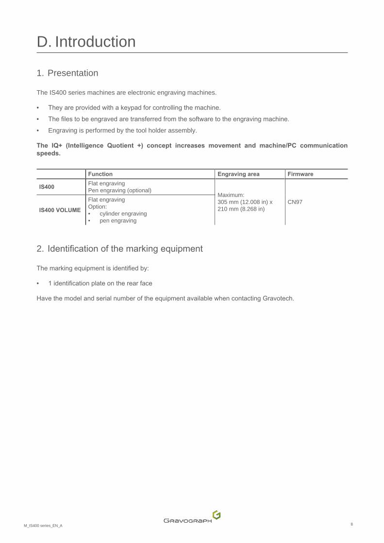
The IS400 series machines are electronic engraving machines.
• Theyareprovidedwithakeypadforcontrollingthemachine.
• Thefilestobeengravedaretransferredfromthesoftwaretotheengravingmachine.
• Engraving is performed by the tool holder assembly.
The IQ+ (Intelligence Quotient +) concept increases movement and machine/PC communication speeds.
Function Engraving area Firmware
IS400 Flat engraving Pen engraving (optional)
Maximum: 305 mm (12.008 in) x 210 mm (8.268 in)
CN97IS400 VOLUME
Flat engraving Option:• cylinder engraving • pen engraving
2. Identificationofthemarkingequipment
Themarkingequipmentisidentifiedby:
• 1identificationplateontherearface
HavethemodelandserialnumberoftheequipmentavailablewhencontactingGravotech.

9M_IS400 series_EN_A
E. Unpacking
1. Unpacking
Unpack the machine with 2 operator(s).
Keepthepackaginginordertomovethemachinesafely.Thispackagingisdesignedtoprotectthemachineduring shipping (return for repair...).
ThepackagingcomplieswithEuropeanrecyclingstandards.
Checkthatnothingismissingfromtheparcel.Ifanythingismissing,contactGravotech.
1. Remove the cardboard.
2. Remove the straps, fastenings and protective elements.
3. Remove the machine from the packaging.
IS400 IS400 VOLUME

10M_IS400 series_EN_A
Unpacking2. Packagecontents
IS400 IS400 VOLUME
- DVD containing the instruction manual - Program Gravostyle
Control panel
Toolbox
StarterkitTwincut
USB cord
Connecting cable(s) (electronic unit / engraving table)
� IS400 VOLUME
- Power cable (VOLUME base)- Power cable (electronic unit)

11M_IS400 series_EN_A
Unpacking � IS400
Longplatesupportkit:- long plate support - 2 support legs
Power cable
3. Toolbox: content
Driver
Ball-tiphexkey
Screwdriver (3.5)
Allenkey(x2)
Screw (x2)
- Jig(s) (standard) - Aluminum jigs
Cutter button(s)
Depth regulating nose
Spindle belt
Brush

12M_IS400 series_EN_A
F. Safety
1. Recommendations and safety
� Personnel safety
For safety reasons, never operate the machine without constant surveillance.
Turnoffthemachinebeforebeginninganycleaning,maintenanceorrepairprocedure.
Never operate the machine without the protective covers properly mounted.
Never hold the materials for engraving by the hands.
Donotstartengravingwithoutfirstensuring that theobject tobeengraved issecurelyclamped.UseonlyGravograph clamping systems designed for the machine.
Nevertakeholdofthematerialforengravingwhenengravingisinprogress.
Keepawayfromtheareaabovethemachine.Ensurethatpeoplearekeptclearoftheareaoftravelofthemovingpartsofthemachineandthatnoobjectsriskobstructingtheirmovement.
Duringengraving,therotationofthespindlecouldpresentrisksofburnsandcuts.Topreventanyriskofburns,thetoolcarrierbelthousingmustbekeptclosedexceptwhenperformingadjustmentoperations.
Warning:Hazardousmovingparts-Keepfingersandotherbodypartsaway.
Keep clear of the tool-holder.

13M_IS400 series_EN_A
Safety � Handling the machine
Any operations on the machine must be carried out under the responsibility of an adult. Do not allow children to touch the machine, leads or cables.
The machine is designed for light engraving only and under no circumstances should it be used for other applications.
Do not use this machine for routing or intensive cutting operations. Donotusethismachineforwoodwork.
Donotusethismarkingequipmentinanexplosiveenvironment.
In the event of an extended period of non-use, unplug the power cable and protect the machine.
Nevermovethetoolholdermanually,exceptintheeventofamechanicalblockageofthemachine.
Neverpouror spill liquidon themachine (drinks, cleaningproducts,etc.)exceptwhere recommendedbyGravotech.
Do not place any object on the machine other than the object to be engraved.
This machine is designed for a single user only. Do not allow its operation by multiple users at the same time.
Duringengravingoperations,usethismachinewitha(regulatingorsuction)noseinordertopreventflyingswarf.
Interrupt engraving by means of the function provided for this purpose on the machine control panel.
Use the machine with Gravograph tools only.
� Wearing safety glasses
Theuseofsafetyglassesisrecommendedforprotectionagainstflyingswarf.

14M_IS400 series_EN_A
Safety 2. Requiredsafetylabels
Do not connect / disconnect when the machine is on.
CAUTION LASER RADIATION
Do not stare into beam.
Laser diode Wavelength: 630-680 nm Output (maximum) < 1 mW
CLASS 2 LASER PRODUCT
Warning: Laser beam Warning: Electricity
Warning: Rotation of the spindle General warning
Refertoinstructionsmanual/booklet.

15M_IS400 series_EN_A
G. Description of the machine
1. Front view of the machine
� IS400
1
2
4
5
3
1. Tool holder assembly 2. Vice 3. Jaws 4. On/Offswitch5. Control panel

16M_IS400 series_EN_A
Description of the machine � IS400 VOLUME
Vice mode
4
12
3
6
5
7
1. Cylinder attachment (optional) 2. Jaws 3. Vice 4. On/Offswitch5. Tool holder assembly 6. VOLUME base 7. Control panel
Cylinder attachment mode

17M_IS400 series_EN_A
Description of the machine � Vice
1
2
4
3
1. Jig(s) 2. Dowel 3. Jaws 4. Handle for opening/closing the vice jaws
1. Separate the jaws by turning the handle (counter-clockwise).
The jaws must be spaced far enough apart so as not to obstruct the mounting of the 2 jigs.
2. Fit the jigs onto the pins on the jaws.

18M_IS400 series_EN_A
Description of the machine � Tool holder
12
3
4
5
610
9
8
7
1. Cutter(s) 2. Cutter button(s) 3. Laser diode 4. Spindle pressure thumbwheel 5. Scaledknob6. Nose nut 7. Belt housing 8. Spindle belt 9. Switch (automatic Z Ref.)10. Index pin

19M_IS400 series_EN_A
Description of the machine � Control panel
Start Start-up engraving
Pause
"Check" key
• Saving parameters • Exit from current menu • Move to next screen • Move to next menu
Undo
• Cancel • Exit from menu without applying change to last parameter • Return to reception, during a pause, during end of reception,
during end of engraving
Rotation of the spindle Spindle rotation activation/deactivation (machine paused)
XY Movement: engraving area
Z Ref. Adjustment: Z Ref.
Pass(es) • Adjustment: number of passes • Adjusting the machine
Joystick• Head movement (X, Y, Z)• Movethecursortodifferentdataentryareas
Spindle rotation speed adjustment button
10000 rpm to 20000 rpm
Detail on the human-machine interface: refer to the user manual for the CN97 program.

20M_IS400 series_EN_A
Description of the machine 2. Rear view of the machine
Eachconnectionmeetsoneofthefollowingsafetylevels:
- dangerous voltage
- SELV (safety extra-low voltage)
2 3 4 5 6 71
1. Power inlet / outlet - Dangerous voltage 2. Connection: machine / IS electronic unit - SELV 3. Connection(s): pen attachment / cylinder attachment - SELV 4. Input/outputlink:externalspindle-SELV 5. Standardinput/outputlink-SELV 6. Connection(s): control panel - SELV 7. Port: USB - SELV
� IS400 VOLUME - VOLUME base
1
2 3
4
1. Connection: VOLUME base / machine - SELV 2. Connection: VOLUME base / IS electronic unit - SELV 3. Power inlet / outlet (VOLUME base) - Dangerous voltage 4. Fuse carrier (Fuse 0.8 A F1T - 110 V x2) - Dangerous voltage

21M_IS400 series_EN_A
H. Recommendations for installation
Turnoff themachinebefore any intervention (put theOn/Offswitch in the "O" (Off)position).
1. Physical installation • IS400:Placethemachineonahorizontal,stableandcleansurfacethatcansupport42kg(92.594lb)or
more (Dimensions: 520 mm (20.472 in) x 500 mm (19.685 in) (minimum)).
• IS400 VOLUME:Place themachineonahorizontal, stableandcleansurface that cansupport90kg(198.416 lb) or more (Dimensions: 640 mm (25.197 in) x 620 mm (24.409 in) (minimum)).
• Place the machine in a clean, ventilated environment.
• Avoidsmall,confined,unventilatedspaces.
• Donotobstructtheeffectiveventilationofthemachine.
• Ambientlightisenoughtolighttheequipmentproperly.
• Arrangetheworksurfaceforrapidandeasyaccesstoeachexternalpartofthemachineand,ifnecessary,to the main machine stop button.
• Do not obstruct the movement of the moving parts of the machine.
Make sure the connector screws are properly tightened to prevent the cables from becoming disconnected while the machine is switched on. This could cause permanent damage to the circuit boards.
Thepowercablemustalwaysbeeasilyaccessible(powershut-offdevice).
• Protecttheequipmentagainst: - damp (rain, snow, condensation etc.)
- heat (exposure to full sun, heating etc.)
- sudden changes in temperature
- dust (extraction duct)
- spillagesofliquidsontotheelectricalunit,cablesandconnections,andallotherpartsofthemachine(except in situations recommended by Gravotech (lubrication)
- vibrations
- electrical/electronic radiation

22M_IS400 series_EN_A
Recommendations for installation � IS400 - Vice + long plate support
1
2
3
1. Dowel 2. Jaws 3. Support legs
1. Separate the jaws by turning the handle (counter-clockwise).
The jaws must be spaced far enough apart so as not to obstruct the mounting of the 2 jigs.
2. Fit the long plate holder onto the pins on the jaws.
3. Tighten the screws of the plate holder feet.

23M_IS400 series_EN_A
Recommendations for installation 2. ITrequirements• Firmware: refer to the user manual for the CN97 program.
• Refer to the user manual for the Gravostyle program.
3. Electrical installation
The connection to the single phase power supply is made with a standard, 3 pin plug withgrounding.Groundingmustbedoneaccordingtotheregulationsineffecttoensurethe safety of the personnel.
Checkthattheelectrical installationmeetstherequirementsof the"Inputpower" label locatedclosetothemachine'spowersupplysocket.
To avoid interference problems due to the external environment, observe the following:
• Usethelinkcablessupplied.TheycomplywithEMCradio-frequencyinterferenceemissionstandardsandprovide protection from external electrical interference (compliant with EMC immunity and susceptibility standards).
• Bringtheitemsofequipmenttobelinkedasclosetogetheraspossibletoreducethelengthofcabletobeused.
• Separatethepowercablefromthelinkcableandmakesurethepowerandlinkcablesdonotrunthroughthe same cable tray.
• Connect the machine direct to a mains power line and avoid connecting more than one device to that line (bypluggingseveraldevicesintothesamemainssocketorintoamulti-wayadapter).Exception:Whereequipmentisconnected,suchasacomputerandthemachine,supplypowertothedevicesthroughthesame mains power line.
• Do not allow inductive or capacitive devices to be connected to the same mains power line as the machine (motors, solenoid valves, chargers, etc.).
• Avoid the installation of manual or automatic switching systems on the same mains power line as the machine(relays,timers,programmers,automaticcircuit-breakers,automaticswitches,etc.).
• Check that devices in the vicinity of themachinemeet the standards for electromagnetic interference(read the technical data sheet for each device). If they are non-compliant, move them as far away from the machine as possible.
• Use the Gravograph accessories.
Alwaysswitchthemachineoffbeforeconnectingordisconnectingacableoroptionalaccessory.

24M_IS400 series_EN_A
I. Connections - Installation
1. Connections
� Power supply connection
Tocutoffthepowertothemachineifthereisaseriousproblem,unplugthepowercableoroperatetheOn/Offswitch(generalstopbutton).
1
2
1
2
3
IS400 IS400 VOLUME
1. Electronic unit 2. Machine 3. VOLUME base
• IS400
1. Connect the control panel to the electronic unit.
2. Connect the machine connection lead to the electronic unit.
3. Tighten the connector screws using the 3.5 screwdriver.
4. Connect the machine to the power supply.
• IS400 VOLUME
1. Connect the control panel to the electronic unit.
2. Connect the VOLUME base connection lead to the electronic unit.
3. Connect the VOLUME base connection lead to the machine.
4. Tighten the connector screws using the 3.5 screwdriver.
5. Connect the machine to the power supply.
6. Connect the VOLUME base to the mains power supply.

25M_IS400 series_EN_A
Connections - Installation � Machine / PC connection
The machine installation and usage procedure is based on a PC-type computer running Windows®. For help, contact Gravotech.
1. Connect the USB cable to the machine's USB port.
2. Connect the USB cable to the PC's USB port.
2. Installation
� Switching on the machine
Placetheswitchinthe"I"position(On).Themachineemitsanaudiblesignal.
Leave the machine powered on, even if it is only going to be used at intervals.
� Resolution of the problems
If the machine does not switch on:
• Checkthatthepowercordiscorrectlypluggedintoboththemachineandthepowersupply.
• Checkthatthereispowertothemainsplug.
• Checktheconditionofthefuse. (see: IS400 VOLUME: changing the fuse (VOLUME base))

26M_IS400 series_EN_A
Connections - Installation � Power down
Setthegeneralstopbuttontothe"O"(Stop)position.
Switchoffthemachineinthefollowingsituations:
• when the operator is permanently leaving the machine
• in theeventofphysicaldamage (something isdroppedon themachine,fire,a liquid isspilledon themachine, etc.)
• mechanical/electrical/electronicfaultssuggestingabreakdown
• if there is a major problem or the machine is jammed mechanically
• themachineisjammedontheparttobeengraved/marked
• themachineisjammedonanobjectintheworkarea
• forced restart
• external/internal cleaning
� Restarting
Ifthemachineortheoperatingprogramlocks,themachinemayneedtoberestarted.
1. Switchoffthemachine.
2. Wait approximately 30 s.
Thiswaitingtimemustberespected.Itpreventsanelectricsurgelikelytodamagethemachine'spowersupply.
3. Switch on the machine.
3. Program installation
Refer to the user manual for the Gravostyle program.

27M_IS400 series_EN_A
J. Using the machine
1. IS400 VOLUME - VOLUME base
� Changing to vice mode or cylinder attachment mode
12
1. Slot 2. Tightening handle
1. Loosen the tightening handle.
2. Pivot the assembly in order to bring the vice or the cylinder attachment into position under the machine spindle.
Usethenotchasamarkertopositiontheviceorthecylinderattachment.
3. Once positioning is complete, check that the buttons and levers have been tightened.
Distancebetweentheobjecttobeengravedandthespindle:10mm(0.394in)(maximum)
� Positioning
Vice mode
1
2
• Openingandclosingthejaws:Separate the jaws by turning the handle.
• Toswitchtoverticalmovement:Move the button upwards to move up, downwards to move down and in the middle to stop moving.
1. Opening and closing the jaws 2. Vertical position
• The spindle must not bang against the jigs or the vice.
• Objects to be engraved can either be clamped between the jaws or between the jigs adapted to their shape.

28M_IS400 series_EN_A
Using the machine Cylinder attachment mode
12
3
4
5
678
• Openingandclosingthejaws:Openorclosethechuckjawsusingtheclampingring.
• To switchtoverticalmovement:Move the button upwards to move up, downwards to move down and in the middle to stop moving.
• Horizontaltravel:Cylinderattachment:Unscrew the handle(s). Move the cylinder attachment with the slider. Tailstockholder:Unscrewthelock(s).Slidethetailstockholderalongtheslide.Fix in position using the clamping handle. Chuckholder: Unscrewthelock(s).Slidethechuckholderalongtheslide.Fix in position using the clamping handle.
1. Clamping ring 2. Chuckholder3. Lock(s)(chuckholder)4. Handle 5. Vertical position 6. Clamping handle 7. Tailstockholder8. Lock(s)(tailstockholder)
Inclination:Unscrew the handle(s). Incline the cylinder attachment to the desired angle and tighten.
• The spindle must not bang against the jaws or the chuck.
• If needed, the part can be inclined so that the engraving area lies perpendicular to the spindle axis.
• If the object has an irregular gradient, incline it to ensure perpendicularity so as to achieve good engraving quality.
Positioning a simple cylinder: see the manual delivered with this option.

29M_IS400 series_EN_A
Using the machine 2. Positioning the object to be engraved (vice)
1. Choose the jigs according to the length of the object to be engraved. Consult a Gravotech retailer tofindoutaboutthevariousjigsavailable.
The length of the object to be engraved must never exceed that of the jigs:
Jig(s)
2. Choose the appropriate side of the jig according to the object to be engraved or the thickness of the plate.
Theplatemustbeslightlyhigherthanthejigsinordertopreventtheregulatingnosefromstrikingthejig.
3. If the Point and Shoot function is not used, mark the mid-point of the length of the object to be engraved.
Jig(s)

30M_IS400 series_EN_A
Using the machine 4. Center the object to be engraved such that the mark on the object is aligned with the 0 notch on
the jig (center origin).
100 mm (3.937 in)
5. Using the tightening knob, clamp the object so as to immobilize it during engraving.
Correctclampinghelpstoreducethenoiseofthemachineandtominimizevibrationduringengraving.
Check that the object is clamped such that it cannot be ejected during engraving.
3. Using the program
Themachineisanoutputperipheral,likeaprinter.
• Firmware: refer to the user manual for the CN97 program.
• Refer to the user manual for the Gravostyle program.

31M_IS400 series_EN_A
Using the machine � PointandShootfunction:definitionoftheengravingzone
1. Select the Point and Shoot function in the Gravostyle programme.
2. Move the spindle to point 1 on the engraving area.
3. Toconfirm,pressthekey: .
4. Move the spindle to the point opposite the engraving area.
5. Toconfirm,pressthekey: .

32M_IS400 series_EN_A
Using the machine 4. Transfer of the composition to the machine
1. Switch on the machine.
2. Check that the machine screen says "Ready to receive".
3. From the program, transfer the composition to the machine (refer to the user manual for the Gravostyle program).
4. A message indicates that the transfer is complete. The machine is ready for operation.
5. Adjustment on the tool holder
� Spindle pressure adjustment
1. Pressonthearrowkeysinsuccession:Start-Pause.
The tool holder stops above the material to be engraved at the point at which engraving is to start.
2. Adjust the spindle pressure with the pressure thumbwheel (counter-clockwise).
Toengravewithoutanose,thepressureknobmustbecompletelytightenedsothatthespindleisrigid.
33M_IS400 series_EN_A
Using the machine � Engraving with a regulating nose
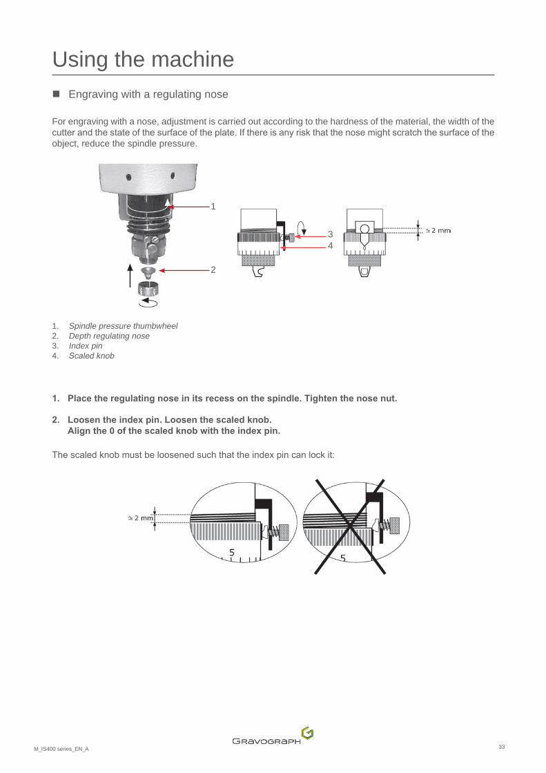
For engraving with a nose, adjustment is carried out according to the hardness of the material, the width of the cutterandthestateofthesurfaceoftheplate.Ifthereisanyriskthatthenosemightscratchthesurfaceoftheobject, reduce the spindle pressure.
1
2
34
1. Spindle pressure thumbwheel 2. Depth regulating nose 3. Index pin 4. Scaledknob
1. Place the regulating nose in its recess on the spindle. Tighten the nose nut.
2. Loosen the index pin. Loosen the scaled knob. Align the 0 of the scaled knob with the index pin.
Thescaledknobmustbeloosenedsuchthattheindexpincanlockit:

34M_IS400 series_EN_A
Using the machine � Mounting the cutter on the tool holder
Because the tool is sharp, use personal protective equipment when handling it.
Carbide cutters are fragile.
It is advisable to have as many cutter buttons as you have cutters, so that they can be left assembled andthesettingssavedifnecessary(materialsofthesamethickness).SavetheconfigurationandtheZRef. (refer to the user manual for the CN97 program).
1. Pressthefollowingkeyonthemachine: .
2. Pressthefollowingkeyonthemachine: .
The tool holder is lowered until the depth regulating nose touches the plate to be engraved.
3. Open the tool carrier housing.
4. Screw cutter button onto the spindle (counter-clockwise).
5. Insert the cutter into the spindle until it comes into contact with the material to be engraved. In order to facilitate the passage of the cutter, slightly loosen the screw on the upper part of the cutter button.
Program0.5mm(0.020in)toadepthof1mm(0.039in)inordertocompensateforanyflatnessdefectsinthe plate.
6. Tighten the screw of the cutter button to lock it into place.
Screw

35M_IS400 series_EN_A
Using the machine � Setting the origin of the tool carrier
Storethepositionofthetoolcarrierbypressingthe"Confirm"key.
The tool holder is raised.
� Adjusting the engraving depth
1. Turn the scaled knob a few notches to the right to obtain the desired engraving depth. 1 division(s) = 0.025 mm (0.001 in)
The number of notches depends on the engraving depth and the material: Material to be engraved Type of cutter Depth Number of notches
Anodized aluminum carbide point 0.1 mm (0.004 in) 4Silver carbide point 0.3 mm (0.012 in) 12Chrome diamond point 0.025 mm (0.001 in) 1Gravometal carbide point 0.1 mm (0.004 in) 4Gravoply II carbide point 0.1 mm (0.004 in) 4Stainless steel diamond point 0.2 mm (0.008 in) 8Brass carbide point 0.2 mm (0.008 in) 8Metallex carbide point 0.1 mm (0.004 in) 4Gold carbide point 0.3 mm (0.012 in) 12Plastic carbide point 0.2 mm (0.008 in) 8
2. Screw the index pin in order to secure the scaled knob in this position.
3. Close the tool-holder housing.
� Spindle rotation speed adjustment button
Speed of rotation: 10000 rpm to 20000 rpm
Spindlerotationactivation/deactivation:pressthekey: (machine paused).

36M_IS400 series_EN_A
Using the machine 6. Start-up engraving
Engraving is launched from the control panel on the machine.
1. Check that the object is correctly positioned in the engraving area.
2. Pressthekey: .
Thetoolholdermovesatasafemovementspeedtothefirstengravingpointandstartstheengraving.
Inordertoachieveafastermovementspeed,presstheStartkeyuntilthefirstengravingpointisreached.
• In the event of a problem, press the Pause button. The machine pauses momentarily. Toresumeengraving,presstheStartkey.
• To stop engraving completely, press one of the arrows on the joystick.
• To accelerate the movement speed of the spindle during engraving, press the Up arrow.
• To slow down the movement speed of the spindle during engraving, press the Down arrow.

37M_IS400 series_EN_A
K. Adaptable accessories Listofaccessoriesavailableuponrequest
1. Pen attachment
This accessory is placed on the vice. Installation - Use: refer to the manual.
Acirculardeviceenablescylindricalpartstobemarked/engraved.
2. Cylinder attachment
This accessory is placed on the vice. Installation - Use: refer to the manual.
Acirculardeviceenablescylindricalpartstobemarked/engraved.Thisaccessoryisdesignedtoholdglasses,mugs, cups, etc.
IS400 IS400 VOLUME

38M_IS400 series_EN_A
Adaptable accessories 3. T-slot table
This accessory is placed on the vice. Installation - Use: refer to the manual.
Enables plates for engraving to be secured in position.
4. Automatic plate feeder (APF)
This accessory is placed on the vice. Installation - Use: refer to the manual.
Enablesaseriesofplatesofidenticalsizetobeloadedandmarked/engraved.
The use of a chip collector is recommended.
5. Type of spindle(s) • Collet spindle
• Highfrequencyspindle(150W)
Installation - Use: refer to the manual.

39M_IS400 series_EN_A
L. Preventive maintenance
1. General maintenance
Unplug the power supply plug before beginning any cleaning or maintenance operation.
The mains power cable must be replaced immediately if it is cut or crushed, cracked or a conductor is stripped bare.
Themachine'smaintenanceneedsdependonthetypeofmaterialused,thequantityofmaterialremoved,frequency of operation, environment and the effectiveness of the air extraction system. It is the user'sresponsibilitytodefinethem.
Dust and debris that accumulate on the machine's components can cause irregular or imprecise engraving, or the loss of the engraving position and the premature failure of components.
Regularlycleaningthemachineimprovesitsoperation,extendsthelifeofpartsandreducestheriskoffailure.
Recommendations:Checkand,ifnecessary,cleanthemachineevery8hoursofengraving/markingorcutting.
For help, contact Gravotech.
Nointernalpartsofthemachinerequireuserintervention.Routinemaintenanceonlyinvolvesexternalcleaningof the engraving area.
Only the following operation(s) can be carried out by the user:
- changing the fuse - changing the spindle belt
To clean other parts of the machine, call a Gravotech technician.

40M_IS400 series_EN_A
Preventive maintenance 2. Changing the spindle belt
1. Open and remove the tool carrier housing.
2. Loosenthe2screw(s)fixingthebelthousing.
3. Unscrew the shaft of the tool carrier housing.
1. Screw 2. Axis
1
2
4. Remove the belt housing.
5. Pull the belt upwards. Rotate the motor pulley.
6. Place the belt in position in the spindle pulley groove.
7. Place the belt in position at the beginning of the motor pulley groove. Rotate the motor pulley.
1. Motor pulley 2. Belt 3. Spindle pulley
1
2
3
8. Replace the belt housing. Tighten the 2 retaining screw(s).
9. Screw the shaft of the tool-holder housing.
10. Replace and close the tool carrier housing.

41M_IS400 series_EN_A
Preventive maintenance 3. IS400 VOLUME: changing the fuse (VOLUME base)
A damaged fuse is the result of a problem on the machine or its environment.
If the new fuse blows, contact an approved Gravotech technician.
Fuse carrier
1. Unplug the power supply cord.
2. Extract the fuse holder with 1 screwdriver(s).
3. Insert the new fuse. Fuse 0.8 A F1T - 110V x2 - (not supplied)

42M_IS400 series_EN_A
Preventive maintenance 4. Adjusting the machine
The center of the engraving area of the machine must be aligned with the clamping system.
The IS400 series machines have a machine reference point adjustment system which can be deployed by the user.
1. Switch on the machine.
2. Pressthekey: .
3. Remove the jigs from the vice.
4. Place the cutter button between the jaws of the vice. Tighten using the tightening knob.
Cutter button(s)
5. Press the "Check" key.
The tool holder moves to the center of the vice.
6. Place the tool in the spindle. The tool must slide easily into the cutter button.
Tool
Ifnot,removethetoolandadjustthepositionofthetoolholderusingthejoystick.
43M_IS400 series_EN_A
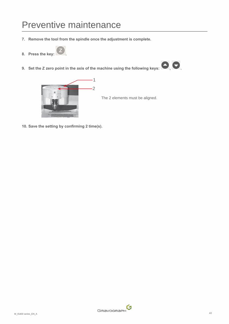
Preventive maintenance 7. Remove the tool from the spindle once the adjustment is complete.
8. Pressthekey: .
9. SettheZzeropointintheaxisofthemachineusingthefollowingkeys: , .
1
2
The 2 elements must be aligned.
10. Savethesettingbyconfirming2time(s).

44M_IS400 series_EN_A
M. Technicalspecifications
1. Physical characteristics
IS400 IS400 VOLUME
Dimensions (L x w x h) 893 mm (35.157 in) x 610 mm (24.016 in) x 435 mm (17.126 in)
900 mm (35.433 in) x 615 mm (24.213 in) x 840 mm (33.071 in)
Net weight 42kg(92.594lb) 90kg(198.416lb)Engraving area Maximum: 305 mm (12.008 in) x 210 mm (8.268 in)
Dimensions(Lxwxh):withpackaging
1100 mm (43.307 in) x 800 mm (31.496 in) x 650 mm (25.591 in)
1100 mm (43.307 in) x 800 mm (31.496 in) x 1150 mm (45.276 in)
Weight:withpackaging 62kg(136.687lb) 97kg(213.848lb)Dimensions(Lxwxh):permissibleobject
Unlimited x 230 mm (9.055 in) x 105 mm (4.134 in)
Weight:permissibleobject Maximum:20kg(44.092lb)Jaws opening Maximum: 230 mm (9.055 in)Height of jaws 75 mm (2.953 in) 76 mm (2.992 in)Passageunderspindle:withjigs 33 mm (1.299 in) 305 mm (12.008 in)
2. Engraving characteristics
Type of spindle(s) Rotating / through spindle with cutter button Diameter (tool) 4.36 mm (0.172 in)Speed of rotation Maximum: 20000 rpmEngraving precision along XY Maximum: 0.012 mm (0.000 in)Surfaceflatness(XY) 0.2 mm (0.008 in)Travel distance Z 40 mm (1.575 in)
� Movement speed
No load XY 150 mm (5.906 in)/sZ 100 mm (3.937 in)/s
Engraving (maximum)
XY 35 mm (1.378 in)/sZ 40 mm (1.575 in)/s
Diamond engraving (maximum)
XY 100 mm (3.937 in)/sZ 100 mm (3.937 in)/s
Speed of acceleration (maximum):No load - Engraving - Diamond engraving
XY 1000 mm (39.370 in)/s²
Z 3000 mm (118.110 in)/s²

45M_IS400 series_EN_A
Technicalspecifications3. Noise emission of the machine (ISO 11201 standard)
LAeq
- when awaiting engraving < 72 dB (A) +/- 1
LAeq
- during nominal engraving 80 dB (A) +/- 2
Lpc
peak - peak at rated engraving < 95 dB (C)
4. Point and shoot
Type Laser diode
Wavelength 630 - 680 nm
Power Maximum: 1 mW
Class Class 2
5. Electrical characteristics
Nominal voltage / Type of current 100 - 240 VAbsorbed current Maximum: 3.5 AFrequency 50-60HzPower 300 WProtection(s) Fuse 5x 20 mm (0.787 in) 4A F1T Degree of protection IP40
� IS400 VOLUME - VOLUME base
Nominal voltage / Type of current 100 - 120 / 230 VAbsorbed current Maximum: 0.8 / 0.3 AFrequency 50-60/50HzPower 25 W
Protection(s) 220 V: fuse 5x 20 mm (0.787 in) 315 mA F1T 110 V: fuse 5x 20 mm (0.787 in) 0.8 A F1T
Degree of protection IP40

46M_IS400 series_EN_A
Technicalspecifications � Spindle motor
Type Direct current
Power IS400: 70 WIS400 VOLUME: 75 W
Absorbed current 2.5 ASpeed 3700 rpm - 7500 rpm
� Displacement motor
Stepper motor 200 step/rev
6. Environment
Operating temperature 5 °C (41 °F) - 40 °C (104 °F)
Storage temperature -5 °C (23°F) - 45 °C (113 °F)
Humidity level IS400: 5 - 85 %
IS400 VOLUME: 20 - 80 %
7. Connection(s)
Port:USB Minimum: 1.1
Control panel Tactile dome membrane
Number of keys 12
Screen LCD screen