is your next pet project a usb battery charging design? - usb.pdf · 22 23 modern test measre tec...
TRANSCRIPT

2322
TECH ARTICLE
2322
Modern Test & Measure
IS YOUR NEXT PET PROJECT A USB BATTERY CHARGING DESIGN?
CEO Saelig Co. Inc. Alan Lowne
USB ports are everywhere, and are rapidly becoming the accepted standard as a universal charging means. But challenges await the designer who wants to make use of USB ports as a convenient charging source. USB-connected device designs are often subject to various constraints such as cost, physical size, and charge time, but yet must work almost anywhere.
Many existing dedicated chargers have offered a USB-compliant physical connection but lacked a USB charging compliance program. This has led to many products having characteristics incompatible with complete USB specifications. And even though PC host ports go through an extensive certification process, PCs that claim a USB compliant Charging Port in their feature list are now required to pass USB-IF compliance checks.Packet-Master USB-PET Compliance
Tester for OTG 2.0 and BC 1.2

2524
TECH ARTICLE
2524
Modern Test & Measure
2524 2524
This specification was created to try to unify battery-charging attributes for USB2.0 – one reason being to minimize the number of cell-phone chargers ending up in landfills. The standard also insures that device manufacturers can deliver their product without a dedicated charger, allowing recharging through any USB port. The USB-IF specification also allows compatibility between computer/hub USB ports and a “USB charger” (an AC-to-DC or DC-to-DC adapter with one or more USB sockets.)
There has been a lot of confusion as to what is possible or permissible in the USB charging world. Many chargers have just put a voltage on the D+ and D- pins of the USB port. Since traditional data communication on the USB is based on 3.3V for USB1.1 and 300mV for USB 2.0, putting a different voltage on these lines removes the possibility for enumeration and communication. If a mobile device has Charging Port Detection capability, it will start a charging session when attached to a USB port and the voltage on VBUS will be greater than its internal session valid threshold. If charging conditions are met, the device will then start the charger detection algorithm of USB-IF BC Rev.1.2.
Some USB devices require you to download device-specific software when you first plug the device into the host’s USB port. Some cell phones are like this for syncing, and some facilitate charging at a higher current while communicating. In the BC 1.2 specification,
there is a mode referred to as Charging Downstream Port (CDP) that allows for data and higher charging currents. If a voltage between 0.4V and 0.8V is sensed on D+ of a host or hub device, then D- should respond with 0.5V to 0.7V. Timing details associated with this specification that can be found in the specification. Once CDP has been established, peripheral devices are allowed to draw up to 1.5A and simultaneously communicate data. A dedicated charging port is a downstream USB port on a device that outputs power through a USB connector but is not capable of enumerating a device connected to it. Examples include plug top chargers which connect to a mains socket and chargers which connect to the low voltage power sockets in automobiles.
All USB power ports, when active (and “not suspended,” in USBspeak) are classified as either “Low Power” (100mA) or “High Power” (500mA). Any port could also be “suspended,” which means almost off but still able to supply 2.5mA. Ports on PCs, laptops, and powered hubs are mostly “High Power,” while ports on hubs that receive no power other than that supplied by the upstream USB host are considered “Low Power.” Once plugged in, a device is allowed initially to draw up to 100mA when enumerating and negotiating the current budget with its host. Subsequently it might be allowed to raise its drain to 500mA, or it might be held at 100mA. This is detailed in the USB Serial Bus Specification Rev 2.0, section 7.2.1.4.
charge from SDPs after enumeration, but may not recognize CDPs and DCPs. If they don’t recognize a CDP, they can still charge but only after enumeration, as with an SDP. A device can implement port detection using its own software, or can employ a charger or interface IC that detects by interacting with the USB D+ and D- data lines without relying on system resources.
USB Connection Terminology
USB terms that might need some explanation include the following:
Attach: Physically plugging in a USB cable.Connect: When the attached device connects a 1.5kohm pull-up to the D+ or D- data lines. Enumerate: This is the initial host/data information exchange to identify device type.Configure: Setting the device parameters.
During the enumeration and configuration information exchange, a USB device decides how much current a USB port can source. In addition to the USB 2.0 options, BC1.2 also allows for charging to take place without enumeration.
Insuring Charging Compliance
In order to create a USB charging design that is reliable, the USB-IF recommends the use of a test device called the USB-PET (Protocol and Electrical Tester) for comprehensive compliance testing. Made by European USB experts MQP, this equipment is capable of emulating and measuring all the electrical conditions and protocol requirements of a
USB Source Types
Three different USB source types are defined in the USB-IF spec:
Standard downstream port (SDP) - This is the typical USB port found in desktop and laptop PCs. The maximum load current is 2.5mA when suspended, 100mA when connected and not suspended, and 500mA (max) when configured for that current. Because SDP only supplies a maximum of 7.5W/500 mA, it belongs to low-speed charging port. A device can recognize an SDP with hardware by detecting that the USB data lines (D+ and D-) are each grounded through 15kohms, but enumerate to be USB compliant. In USB 2.0, it is not correct to draw power without enumerating. However, many USB products do in violation of the spec.
Charging downstream port (CDP) - A higher current USB port for PCs, laptops, and other hardware which can supply up to 1.5A. This current can be supplied before enumeration. A USB device can recognize a CDP via a hardware handshake on the D+ and D- lines. (See USB Battery Charging Specification, section 3.2.3.) The hardware test occurs prior to returning the data lines to a communication function. So a CDP can be detected and charging starts before enumeration.
Dedicated charging port (DCP) - These are power sources like wall chargers and car adapters that do not enumerate so charging can start without enumeration. DCPs can supply up to 1.5A and are identified by a short between D+ to D-. These adapters allow any USB cable to be used for charging USB devices. Detecting the Source
Any device that connects to a USB receptacle and uses that power to run itself or charge a battery needs to know how much current it can draw. Trying to draw 1A from a source capable of supplying only 500mA could create problems like blown fuses or shutdowns.
USB products can be designed to be compliant with BC1.2, compliant only with USB2.0, or noncompliant. BC1.2-compliant designs must be able to sense and limit input current for all USB source types, including legacy USB 1 and 2.0 ports. USB2.0-designed products can
USB Car Charging Adapter
The USB-IF Battery Charging Specification, Revision 1.2 offers a good basis for building interoperable and compatible USB devices from the battery-charging standpoint.
2726
TECH ARTICLE
2726
Modern Test & Measure
USB host, a USB device, an OTG device, an Embedded Host, an OTG Peripheral-Only device, a Charging Downstream Port, or a Dedicated Charger Port. It can also perform a series of compliance tests on a Micro-ACA or Standard-ACA.
The PET is controlled by a script, which is flexible enough to allow complete emulation as a host or peripheral. A set of standard scripts is provided with the PET for confirming the operation of devices designed to meet the OTG 2.0 and/or Battery Charging 1.2 specifications. With BC 1.2, a Portable Device can get more power and the battery can be charged faster. The PET can be used to verify that a Portable Device complies with the BC 1.2 specification while communicating with a Charging Downstream Port and identifying a Dedicated Charger, and insuring that it continues to operate as a functional USB device.
The PET (Protocol and Electrical Tester) is best described in terms of a number of functional blocks:
1.1 Serial Interface Engine (SIE)A fully functional SIE, with both host and peripheral capabilities, connected via a PHY to the UUT micro-AB receptacle on the front panel. It is under the control of the Script Processor.
1.2 Electrical Test Board (ETB)This contains circuitry to allow control and measurement of the electrical parameters for USB, OTG and BC specifications. It includes VBUS Generator, ID pin circuitry, data line test mode circuitry, VBUS current and voltage loads, and a variety of voltage and current measuring blocks. Extra connections are provided on the front panel to enable the testing of Accessory Charger Adapters (ACAs).
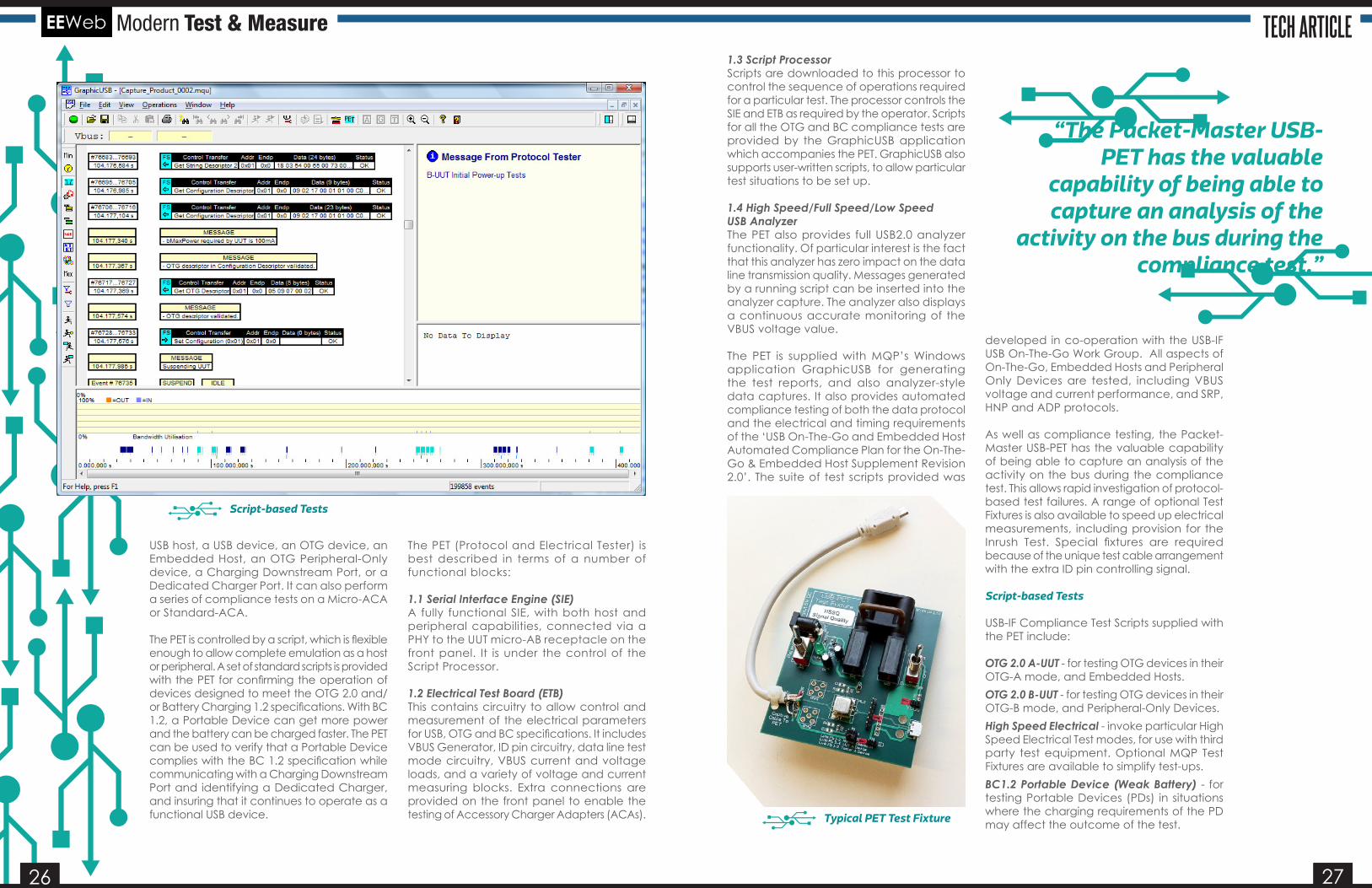
1.3 Script ProcessorScripts are downloaded to this processor to control the sequence of operations required for a particular test. The processor controls the SIE and ETB as required by the operator. Scripts for all the OTG and BC compliance tests are provided by the GraphicUSB application which accompanies the PET. GraphicUSB also supports user-written scripts, to allow particular test situations to be set up.
1.4 High Speed/Full Speed/Low Speed USB AnalyzerThe PET also provides full USB2.0 analyzer functionality. Of particular interest is the fact that this analyzer has zero impact on the data line transmission quality. Messages generated by a running script can be inserted into the analyzer capture. The analyzer also displays a continuous accurate monitoring of the VBUS voltage value.
The PET is supplied with MQP’s Windows application GraphicUSB for generating the test reports, and also analyzer-style data captures. It also provides automated compliance testing of both the data protocol and the electrical and timing requirements of the ‘USB On-The-Go and Embedded Host Automated Compliance Plan for the On-The-Go & Embedded Host Supplement Revision 2.0’. The suite of test scripts provided was
developed in co-operation with the USB-IF USB On-The-Go Work Group. All aspects of On-The-Go, Embedded Hosts and Peripheral Only Devices are tested, including VBUS voltage and current performance, and SRP, HNP and ADP protocols.
As well as compliance testing, the Packet-Master USB-PET has the valuable capability of being able to capture an analysis of the activity on the bus during the compliance test. This allows rapid investigation of protocol-based test failures. A range of optional Test Fixtures is also available to speed up electrical measurements, including provision for the Inrush Test. Special fixtures are required because of the unique test cable arrangement with the extra ID pin controlling signal.
Script-based Tests
USB-IF Compliance Test Scripts supplied with the PET include:
OTG 2.0 A-UUT - for testing OTG devices in their OTG-A mode, and Embedded Hosts.OTG 2.0 B-UUT - for testing OTG devices in their OTG-B mode, and Peripheral-Only Devices.High Speed Electrical - invoke particular High Speed Electrical Test modes, for use with third party test equipment. Optional MQP Test Fixtures are available to simplify test-ups.BC1.2 Portable Device (Weak Battery) - for testing Portable Devices (PDs) in situations where the charging requirements of the PD may affect the outcome of the test.Typical PET Test Fixture
Script-based Tests
“The Packet-Master USB-PET has the valuable
capability of being able to capture an analysis of the
activity on the bus during the compliance test.”
2828
Modern Test & Measure
2828
BC1.2 Portable Device (Good Battery) - tests aspects of Portable Devices (PDs) where it is undesirable that the PD should be drawing significant charging current.BC1.2 Portable Device (Dead Battery Provision) - tests Portable Devices’ (PDs) adherence to the Dead Battery Provision.BC1.2 Micro-ACA (Separate Charger) - for testing Micro-Accessory Charger Adapters (Micro-ACAs) which have a port for a separate chargerBC1.2 Micro-ACA (Combined Charger) - for testing Micro-Accessory Charger Adapters (Micro-ACAs) which have a combined charger.BC1.2 Standard-ACA (Separate Charger) - for testing Standard-Accessory Charger Adapters (Standard-ACAs) which have a port for a separate charger.BC1.2 Standard-ACA (Combined Charger) - tests Standard-Accessory Charger Adapters (Standard-ACAs) which have a combined charger.BC1.2 DCP - for testing Dedicated Charging Ports (DCPs).BC1.2 CDP - used for testing Charging Downstream Ports (CDPs). BC1.2 SDP - tests Multiple Role Ports when configured as Standard Downstream Ports (SDPs).
BC1.2 Multiple Role Port (MRP) - for testing that Multiple Role Ports (i.e. ports which change between CDP, CDP and SDP) perform suitable handshaking.BC1.2 ACA-Dock - for testing ACA-Docks.
Conclusion
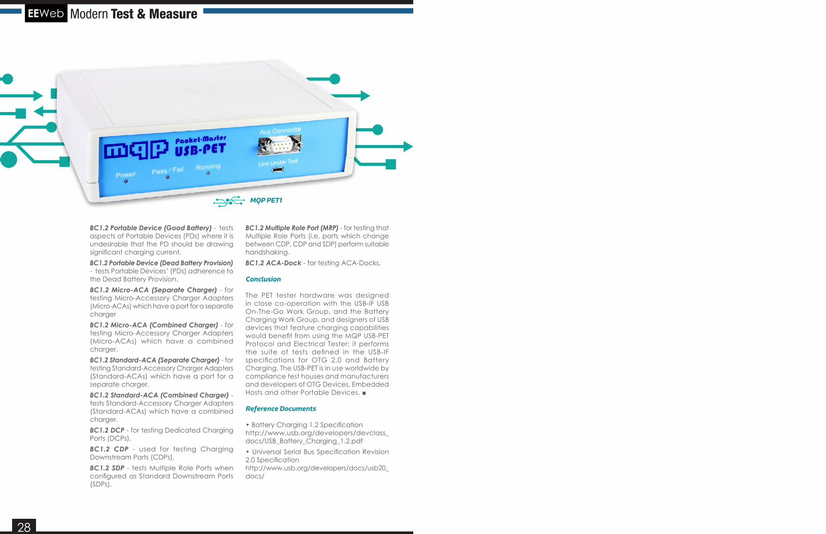
The PET tester hardware was designed in close co-operation with the USB-IF USB On-The-Go Work Group, and the Battery Charging Work Group, and designers of USB devices that feature charging capabilities would benefit from using the MQP USB-PET Protocol and Electrical Tester; it performs the suite of tests defined in the USB-IF specifications for OTG 2.0 and Battery Charging. The USB-PET is in use worldwide by compliance test houses and manufacturers and developers of OTG Devices, Embedded Hosts and other Portable Devices. ■
Reference Documents
• Battery Charging 1.2 Specification http://www.usb.org/developers/devclass_docs/USB_Battery_Charging_1.2.pdf• Universal Serial Bus Specification Revision 2.0 Specification http://www.usb.org/developers/docs/usb20_docs/
MQP PET1