is f. in - geographical & earth sciences · pursue when designing and building his various...
TRANSCRIPT

Photogrammetric Record, 9(50): 213-238 (October 1977)
A SHORT HISTORY OF BRITISH STEREOPLOTTING INSTRUMENT DESIGN
By G. PETRIE University of Clasgow
Abstract A history and analysis of stereoplotting instrument design and
construction in the United Kingdom is given, beginning with the earliest instruments of F. V. Thompson dating from 1907 and 1908 and covering all known designs up till the late 1960s. In the first part of the paper, the instruments built in the 1920s and 1930s are described, much new information having come to light recently in the archives of Barr and Stroud Ltd. and in the papers of the late Professor E. H. Thompson. In the second part of the paper, the instruments which were produced during and after the Second World War are discussed in detail, with an emphasis on those designs which are less well known rather than those which were produced in quantity. The ideas and designs of Deville, F. V. Thompson, Fourcade and E. H. Thompson have been the dominating influences throughout the period and a strong thread of continuity can be established between them.
INTRODUCTION SINCE this paper was given at the Thompson Memorial Symposium, it should be and will be concerned with the contributions made by Professor E. H. Thompson to the field of stereoplotting instrument design and construction. However, I am not going to cover the detailed design and construction of the various models of the Thompson-Watts Plotter, most of which are still in use today; nor am I going to deal with the CP1 Plotter, his last design, which dates from 1971 and is still being manufactured by Cartographic Engineering Ltd. One can read the appropriate papers in The Photogrammetric Record and easily see these machines in action in many places at the present time. Instead, I want to try to trace the history of British stereoplotting instruments from the earliest days of photogrammetry. Professor Thompson is inevitably one of the major figures in this story but, by starting earlier, one can set and assess his contributions in the context of the circumstances which prevailed when they were made. Also one can endeavour to trace the various influences which caused him to follow the lines which he did pursue when designing and building his various instruments.
Yet another reason for going back to the beginning is that the story of the design and development of the many older British instruments is little known to most British photogrammetrists. Many of the instruments were sponsored by military agencies which, for security reasons, did not wish to give publicity to their efforts. Details of quite a number of these instruments were never published or were published in rather obscure places; there was of course no Photogrammetric Record at the time! Recently, however, a great deal of new and hitherto unpublished
213
information has come to light with the discovery of many old files and numerous drawings, relating to the many photogrammetric instruments which were constructed by Barr and Stroud Ltd., which are still preserved in the firm’s archives in Glasgow. Further material of a similar character has also emerged from Professor Thompson’s papers, mainly through the efforts of K. B. Atkinson. So much new material has emerged, especially from Barr and Stroud, that it has only been possible to go through it very rapidly in the short time between its discovery and this Memorial Symposium. The present author is therefore very aware that one or two aspects of this paper may well need revision when more detailed research into this material has been made and more time is available for a comprehensive assessment. Therefore this paper must be regarded as an interim report and not as a definitive history of this subject.
EARLY INFLUENCES Three of the dominating influences throughout the period were E. Deville,
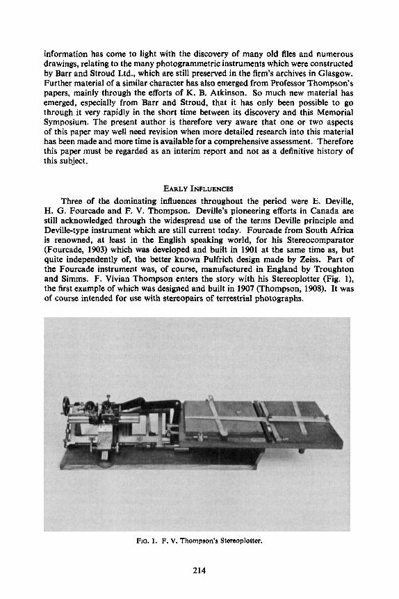
H. G. Fourcade and F. V. Thompson. Deville’s pioneering efforts in Canada are still acknowledged through the widespread use of the terms Deville principle and Deville-type instrument which are still current today. Fourcade from South Africa is renowned, at least in the English speaking world, for his Stereocomparator (Fourcade, 1903) which was developed and built in 1901 at the same time as, but quite independently of, the better known Pulfrich design made by Zeiss. Part of the Fourcade instrument was, of course, manufactured in England by Troughton and Simms. F. Vivian Thompson enters the story with his Stereoplotter (Fig. l), the first example of which was designed and built in 1907 (Thompson, 1908). It was of course intended for use with stereopairs of terrestrial photographs.
Fro. 1 . F. V. Thompson’s Stereoplotter.
214

F. V. THOMPSON’S STEREOPLOTTER In principle, Vivian Thompson’s instrument was a simple stereocomparator to
which two hea ls were attached (Fig. 2). The left hand lineal gave the direction from the left hand perspective centre towards the measured point. The right hand lineal gave the vertical angle (above the horizontal) towards the same point, again as measured at the left hand perspective centre. In addition, the parallax measuring
Scale on whlch measured parallax readln; It set
Y 4 station Movement
FIG. 2. Principle of F. V. Thompson’s Stereoplotter.
device of the comparator gave the range to this point, which was read off a specially graduated drum. This range was then set manually on a distance piece which allowed the left hand lineal to locate the plan position of the point and the right hand lineal to generate the height value on a suitable scale. So plotting proceeded point by point. Each plotted point could have the height value added and contours could be interpolated later. The Stereoplotter was not, therefore, a fully automatic stereo- plotting instrument; the intermediate manual step of setting the distance piece had to be undertaken before the position and height could be generated.
The matter of continuous plotting was solved later in an instrument devised by the Austrian, von Orel, whose design was built by Zeiss as the Stereoautograph. However, as Professor Thompson showed (Thompson, 1973), F. V. Thompson had also designed a fully automatic plotter in 1908 which he called the Stereo-planigraph. Unfortunately this instrument was never built. However, three examples of his Stereoplotter which were manufactured by W. Watson and Sons of London are still preserved in the London Science Museum. Yet another was known to be in existence in Pakistan some years ago, though its present whereabouts are unknown.
THE PERIOD AFTER THE FIRST WORLD WAR The development of stereoplotting instruments in general was interrupted by
the First World War, but the six or seven year period which followed was marked by intense research and rapid development of these instruments, with an emphasis on their application to aerial rather than terrestrial photographs. It was in this period that the basic principles of all the now familiar types of analogue instruments were laid down. These pioneering instruments included Nistri’s Photocartograph (1919) and Bauersfeld’s Zeiss Stereoplanigraph (1923) optical projection instruments; Santoni’s Autoriduttore (1920) and Stereocartograph I (1925) mechanical projection instruments; and Hugershoff’s Autokartograph (1921), Poivilliers’ Stereotopograph A (1923), Hugershoff’s Aerokartograph (1926) and Wild’s Autograph A2 (1926) optical-mechanical instruments. In the United Kingdom, a parallel and largely
215

independent development took place which centred on the development of optical and optical-mechanical projection instruments.
THE MACLEOD TILT FINDER The British story continues, however, not with a stereoplotting instrument, but
with MacLeod‘s Tilt Finder of 1923 (Mackod, 1923). Slightly different drawings and photographs (Fig. 3) of the device exist, but they all show the same basic
FIG. 3. The MacLeod Tilt Finder.
arrangement (Fig. 4) by which an observer viewed through a pinhole and achieved coincidence of a series of control points plotted on a screen with the corresponding points appearing on a suitably enlarged aerial photograph placed on the easel or photocarrier at the foot of the instrument. Both the screen and the photocarrier could be tilted around two mutually perpendicular axes. Also the distances between the easel and screen and the pinhole and screen could be varied to achieve correct scale. An experimental model of the Tilt Finder was constructed by the Ordnance Survey and a second example by the Royal Aircraft Establishment, Farnborough. Although MacLeod later became a Major-General and the Director-General of the Ordnance Survey, the Survey itself forgot all about his Tilt Finder, only to re-invent it many years later in the form of the Blogg Tilt Finder. The description of the “new” Tilt Finder by Jenney in the paper which he gave to the Conference of Commonwealth Survey Officers at Cambridge in 1951 resulted in a rather em- barrassing situation, both for the author and MacLeod, by then retired but a participant in the Conference (Jenney, 1955). The Blogg Tilt Finder is still in use at the Ordnance Survey today (Matthews, 1976).
216

It is now quite difficult to realise that, at the time when the Tilt Finder was devised, relative orientation procedures had not been worked out. Thus a pre- requisite for all photogrammetric work was the discovery of the amount and direction of tilt for each photograph, either for later rectification or in order to orient the photography in a stereoplotter. This may help to explain some of the unusual characteristics of the first British stereoplotting instrument design which could handle aerial photographs, the Barr and Stroud ZAl.
FIG. 4. Diagram of the MacLeod Tilt Finder (from MacLeod, 1923).
THE BARR AND STROUD PLOTTING APPARATUS In fact, the instrument formed part of what was then termed the Barr and
Stroud Plotting Apparatus and would now be called a plotting system with its two complementary devices, the ZB1 Tilt Finder and the ZAl Stereo-plotter. These were designed by Archibald Barr, Regius Professor of Civil and Mechanical Engineering at the University of Glasgow from 1889 until 1913 when he resigned to devote himself, full time, to the firm of scientific instrument makers which he had established in Glasgow in collaboration with William Stroud, formerly Cavendish Professor of Physics at the University of Leeds. Dr. Barr appears to have started work on the design in 1923. The War Office, which was the principal agency interested in employing such a system for mapping, placed the formal order in February 1925, the completed instruments being delivered early in 1927. They were designed specifically to accommodate photography taken with the then new F8 camera used by the Royal Air Force. The whole project went forward under a fair
217

degree of confidentiality and since Dr. Barr never published an account of his designs, it was left to M. Hotine, who had been Air Survey Research Officer at the War Office during this period, to give a description of the plotting instrument (Hotine, 1930) just before Barr’s death in 1931. Hotine was then engaged in public debate (even combat) with continental photogrammetrists on a variety of topics and his account was written against this background and should be read accordingly. Hotine only mentions the MacLeod Tilt Finder in passing: in fact the ZB1 Tilt Finder (Fig. 5 ) was an integral part of the system and was substantially different in both design and construction to the MacLeod instrument (Anon., 1927).
FIG. 5. Ban and Stroud ZB1 Tilt Finder.
For example, the map screen on which the control points were plotted is in the easel position furthest from the projection centre. Over each control point, a small table was placed on which the appropriate height value could also be set. The diapositive on which the control points were marked was located in the central part of the instrument (Fig. 6). Prisms were placed over these pricked points and the point light source was turned on. The rays passed, via the prisms, through the marked control points and then through a pinhole diaphragm on to the series of screens with crosshairs marking the control points. The four control points on the diapositive were made to fit by increasing or decreasing the projection distance and by rotating and tilting the photograph. The plumb point or nadir point could then be marked, the direction and the angle of tilts read off the scales and the z-value determined. These factors could then be used to orient the Stereo-plotter.
The ZAI Stereo-plotter (Fig. 7 ) was, in principle, similar to the Zeiss Stereo- planigraph; that is to say, it was based on the Porro-Koppe principle, utilising pure optical projection and an auxiliary focussing system for each projector. The projectors were set horizontally, as was the case with the C1 to C3 models of the
218

Marked Refkctin; Prima Control (adjustable In porirlon)
c-
4 Projector
FIQ. 6. Diagram of the Barr and Stroud ZB1 Tilt Finder.
FIG. 7. Diagram of the main elements of the Barr and Stroud ZAl Stereo-plotter (from Hotine, 1930).
Stereoplanigraph and a Y/Z interchange between hand wheels was provided to allow terrestrial photographs to be plotted. However, there were also many differences which can be summarised as follows :
6)
(ii)
(iii)
(iv) . control of the handwheels- (whichalso moved the projectors). The board was thus moved past a pencil fixed to the stereoscope/comparator unit. The latter could, however, be freed to scan the area of the screens, in which case the pencil moved relative to the drawing surface over this limited area. Thus the operators could also carry out free hand plotting by utilising handles to control the movement without the need to employ the handwheels.
From the factory records, it appears that there were many difficulties with the mechanical aspects of the instrument and with the auxiliary focussing systems, not all of which were resolved satisfactorily in this prototype machine.
the X, Y and Z shifts of the handwheels provided scanning of the stereomodel by movements of the projectors or plotting cameras; the auxiliary focussing systems for each photograph were located at the mid- projection distance between the projectors and the viewing screens (Fig. 8). Shifts of X/2, Y/2 and 212 were imparted to these auxiliary systems correspond- ing to shifts X, Y and Z of the projectors; the two images were projected on to two screens located side by side in front of the binocular viewing system. Viewing of the area of the screens was by a single stereoscope containing floating marks mounted on a parallel guidance or comparator system (Fig. 9); and DIottina was carried out by moving the drawing board in X and Y under the
219

I3
FIG. 8. Cross section showing the optical projeotion and viewing system of the Barr and Stroud ZAl Stereo-plotter.
FIG. 9. Barr and Stroud ZAl Stereo-plotter.
Tilts were set from the ZB1 Tilt Finder information, so the photograph could be rotated into the direction of tilt and then the tilt was imparted to the projector. In this way the model was formed. With such an arrangement, it would not be possible to carry out the now familiar relative and absolute orientation procedures. Indeed Hotine (1930) acknowledged that, in a new model, it would be necessary to have a rotation of the photograph in its own plane and two tilts about the X and Y axes to allow a relative orientation to be carried out. However, no further develop- ment of the ZAl/ZBl combination took place. Hotine (1930) asserted that this lack of further development was “not because the instruments were considered inferior to their Continental counterparts but as a result of the introduction of the Stereogoniometer and the perfection of simple approximate methods of detail plotting”. The ZAl instrument eventually made its way to the London Science
220
Museum where it was on display for many years before being displaced by the prototype Thompson-Watts Plotter. The instrument still exists in pieces in a Science Museum store.
FOURCADE’S STEREOGONIOMETER While the ZAl was still being built, Barr and Stroud and the War Office were
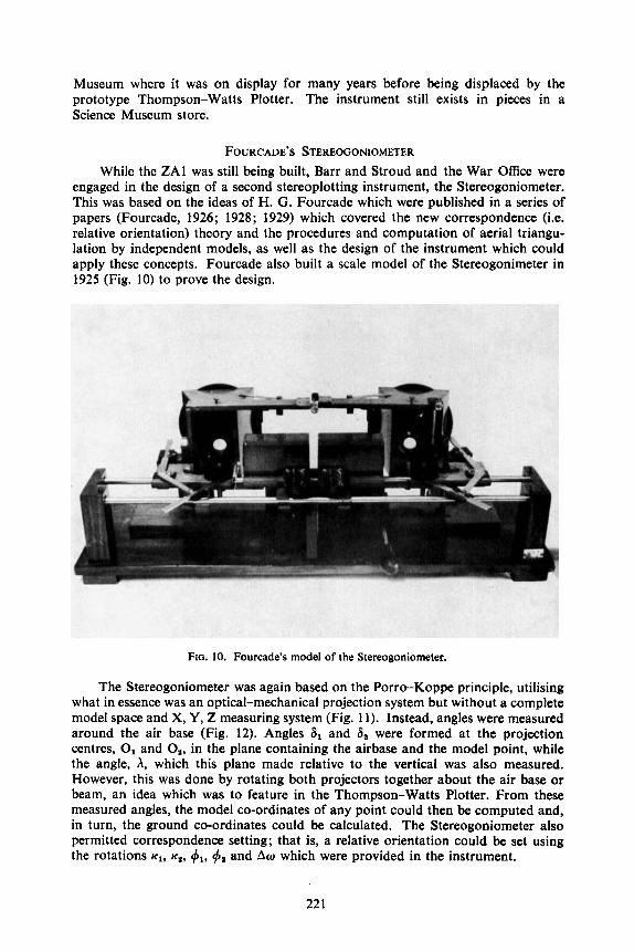
engaged in the design of a second stereoplotting instrument, the Stereogoniometer. This was based on the ideas of H. G. Fourcade which were published in a series of papers (Fourcade, 1926; 1928; 1929) which covered the new correspondence (i.e. relative orientation) theory and the procedures and computation of aerial triangu- lation by independent models, as well as the design of the instrument which could apply these concepts. Fourcade also built a scale model of the Stereogonimeter in 1925 (Fig. 10) to prove the design.
FIG. 10. Fourcade’s model of the Stereogoniometer.
The Stereogoniometer was again based on the Porro-Koppe principle, utilising what in essence was an optical-mechanical projection system but without a complete model space and X, Y, Z measuring system (Fig. 11). Instead, angles were measured around the air base (Fig. 12). Angles 8, and 8, were formed at the projection centres, 0, and 08, in the plane containing the airbase and the model point, while the angle, A, which this plane made relative to the vertical was also measured. However, this was done by rotating both projectors together about the air base or beam, an idea which was to feature in the Thompson-Watts Plotter. From these measured angles, the model co-ordinates of any point could then be computed and, in turn, the ground co-ordinates could be calculated. The Stereogoniometer also permitted correspondence setting; that is, a relative orientation could be set using the rotations K,, K ~ , I$,, d l and Aw which were provided in the instrument.
221

Observer A A
Mlrror trinalitcd and routed to MW
the oprlcal JXIS
FIG. 1 1 . Principle of Fourcade's Stereogoniometer. p'- X
I ,' ---A-
2
FIG. 12. Angles S,, Sp and X measured by the Stereogoniometer.
BARR AND STROUD ZG 1 STEREOOONIOMETER The War Office Air Survey Committee was much impressed with the whole
concept and, after some discussion, a contract was let to Barr and Stroud in October 1927 to construct an instrument which was based on the Fourcade model. This was the ZG1 Stereogoniometer (Fig. 13) which was delivered in 1930. While the general principle and arrangement of Fourcade's prototype was followed, the ZG1 differed in many details, especially in the optical design and in the devices for tracking and measurement (Fig. 14). The instrument was built to accommodate photographs taken with an f = 6.25 inch (160mm) lens on a half plate ( 6 5 ~ 4 . 7 5 inch or 165 x 120 mm) format. It was also built to accommodate convergent photography for Fourcade saw clearly that this would provide a greater base : height ratio and a greater accuracy of pointing. Thus the projectors could be rotated from a position of 35" inwards to 5" outwards (Fig. 15). However, neither Fourcade nor Barr and Stroud foresaw the optical difficulties which would result. For example, there was a need for a pancratic system to equalise the scale of the two corresponding
222

FIG. 13. Barr and Stroud ZG1 Stereogoniometer.
( X movement)
FIG. 14. Plan drawing of the Barr and Stroud ZG1 Stereogoniometer.
images and image rotations would be necessary. However, it appears that the ZG1 was invariably used with near vertical photography.
The ZG1 seems to have been viewed by Hotine, the Research Officer who carried out all the initial test work on the machine, primarily as an instrument which would provide control by aerial triangulation (Hotine, 1931). In particular he
223
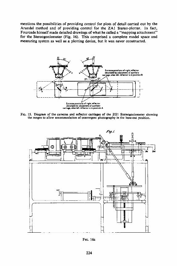
mentions the possibilities of providing control for plots of detail carried out by the Arundel method and of providing control for the ZAl Stereo-plotter. In fact, Fourcade himself made detailed drawings of what he called a “mapping attachment” for the Stereogoniometer (Fig. 16). This comprised a complete model space and measuring system as well as a plotting device, but it was never constructed.
Extreme positions of right refkcor obtamabkty adjustment of JUXIIIJV
carriage whcn Wr r d b r o r II In posltion A
FIG. IS. Diagram of the cameras and reflector carriages of the ZG1 Stereogoniometer showing the ranges to allow accommodation of convergent photography in the base-out position.
fy.1 n
j I
FIG. 16a
224
J
- ~~
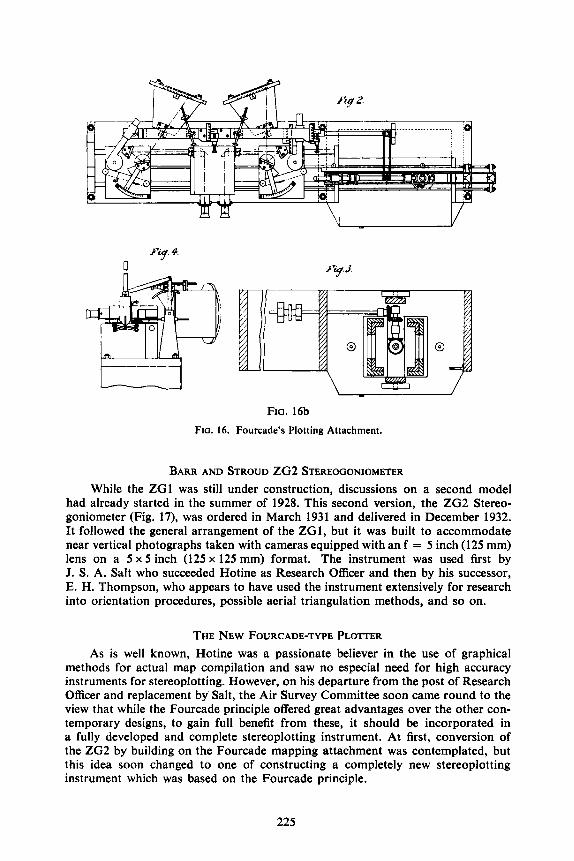
FIG. 16b FIG. 16. Fourcade’s Plotting Attachment.
BARR AND STROUD Z G 2 STEREOGONIOMETER While the Z G 1 was still under construction, discussions on a second model
had already started in the summer of 1928. This second version, the ZG2 Stereo- goniometer (Fig. 17), was ordered in March 1931 and delivered in December 1932. It followed the general arrangement of the ZG1, but it was built to accommodate near vertical photographs taken with cameras equipped with an f = 5 inch (125 mm) lens on a 5 x 5 inch (125 x 125 mm) format. The instrument was used first by J. S. A. Salt who succeeded Hotine as Research Officer and then by his successor, E. H. Thompson, who appears to have used the instrument extensively for research into orientation procedures, possible aerial triangulation methods, and so on.
THE NEW FOURCADE-TYPE PLOTTER As is well known, Hotine was a passionate believer in the use of graphical
methods for actual map compilation and saw no especial need for high accuracy instruments for stereoplotting. However, on his departure from the post of Research Officer and replacement by Salt, the Air Survey Committee soon came round to the view that while the Fourcade principle offered great advantages over the other con- temporary designs, to gain full benefit from these, it should be incorporated in a fully developed and complete stereoplotting instrument. At first, conversion of the Z G 2 by building on the Fourcade mapping attachment was contemplated, but this idea soon changed to one of constructing a completely new stereoplotting instrument which was based on the Fourcade principle.
225

FIG. 17. Baa and Stroud ZG2 Stereogoniometer.
Barr and Stroud proceeded with the design, their chief designer, Claude Foster, working in collaboration with Salt and members of the Air Survey Committee. G. T. McCaw appears to have played an active part with suggestions for improve- ments and modifications and further ideas came from the Canadian Department of National Defence which had indicated that it would be likely to place an order for the new instrument. A letter from E. L. M. Burns (who later devised the Canadian High Oblique Plotter) shows that the Canadians were unhappy with the f = 5 inch (125 mm) lens and the 5 x 5 inch (125 x 125 mm) format which was proposed and that they wanted the new instrument to accommodate fore and aft (or convergent) obliques and lateral obliques. In December 1934, Burns and a collehgue inspected the design drawings at Barr and Stroud on their way back from participation in the International Congress of Photogrammetry in Paris.
Salt had been transferred from his post as Research Officer to the Air Survey Committee in the middle of 1934. His successor was E. H. Thompson who took up the position towards the end of 1934 and immediately began his collaboration with Claude Foster, suggesting a number of changes and improvements. Thompson next made a Meccano mock-up in order to prove the practicality of the new design. Between 23rd July and 2nd August, 1935, the Conference of Empire Survey Officers was held in London and this gave Thompson the opportunity to present a paper on the new design (Thompson, 1936). This was published in the Conference Proceedings and the drawing (Fig. 18) was widely reproduced elsewhere in textbooks as, for example, in Talley (1938).
The proposed instrument had the following distinctive features : (i) the plotting cameras and the projection system were placed in a vertical position
compared with the horizontal position used in all of the previous Stereo- goniometers. A similar repositioning from a horizontal to vertical position had taken place with the C4 model of the Zeiss Stereoplanigraph produced from 1932 onwards;
226
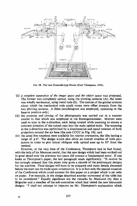
FIG. 18. The new Fourcade-type Plotter (from Thompson, 1936).
(ii) a complete separation of the image space and the object space was proposed. The former was completely optical, using the plotting cameras (A); the latter was wholly mechanical, using metal rods (E). The centres of the gimbal systems about which the mechanical rods could rotate were offset inwards from the two plotting cameras. A Zeiss parallelogram was employed, operating in the base-in position only;
(iii) the scanning and viewing of the photographs was carried out in a manner similar to that which was employed in the Stereogoniometer. Mirrors were used to scan in the x-direction, each being rotated while scanning to ensure a constant direction of the output rays into the main optical train. The scanning in the y-direction was performed by a simultaneous and equal rotation of both projectors around the air base (the axis CCCC in Fig. 18); and
(iv) the usual five rotations were available for relative orientation, the tilts having a range of f 6’. The design would also allow an overall rotation of both pro- jectors in order to plot lateral obliques with optical axes up to 35” from the vertical. However, at the very time of the Conference, Thompson had in fact found,
with the help of his Meccano model, that the new design which had been worked out in great detail over the previous two years did contain a fundamental error. If one looks at Thompson’s paper, the last paragraph reads significantly: “It cannot be too strongly stressed that this paper only gives a rksum6 of the preliminary designs for the machine. Final designs will have to be prepared and many details discussed before the start can be made upon construction. It is in fact only the special occasion of the Conference which could account for this paper on a project which is yet only on paper. For example, in the design described another movement of the table has to be considered.” Equally significant are the remarks by MacLeod (by then a Brigadier and a member of the sub-committee which had vetted the new intrument design): “I shall not attempt to improve on Mr. Thompson’s explanation which
19 227

seemed to me an admirable demonstration of the principles governing the design of this type of machine. Automatic plotting machines are very difficult things to understand and, although he has not mentioned it, I think I may say that one or two of the snags which have been encountered are snags which were overlooked by everybody except Mr. Thompson himself.”
What were these snags? A search through the archives of Barr and Stroud has brought to light the following letter to Foster, written by Thompson on 19th August, 1935. This was 17 days after the end of the Conference.
“Dear Mr. Foster, There has been a slight set-back (!!) with regard to the plotter. I have discovered
that it is theoretically impossible to allow the board to move in any way except perpendicular to itself. Although some form of corrector will enable heights to be measured correctly if the board moves as we have suggested, you will see that the plan positions are bound to be incorrectly plotted. The general effect is that of a crabbing of the detail in a direction of the line of greatest slope of the board.
As you expressed your unwillingness to design a board that tilted and at the same time moved perpendicular to itself, I have gone over the whole situation again and have come to the conclusion that the best thing will be to keep the drawing board fixed and put both tilts on the air base and goniometers. The height movement I propose would be best done by moving the intersection of rods up and down and not moving the board. The intersection is lighter than the drawing board and it is an advantage to have the drawing board fixed at a definite height. It also allows the plotting rods to run in sleeves at their lower end and be fixed at their upper end, an arrangement which you once told me you would prefer.
I am coming to Glasgow on August 30th with Major Burns. If you could give this a little thought by then we could perhaps be able to discuss it. It is unfortunate that I did not discover this error sooner but fortunate that I discovered it before we had got any further with the design.”
On 30th August, 1935, Thompson visited the Barr and Stroud factory with Burns, who had come over for the Conference, in order to discuss the matter further and also to inspect the progress that was being made with the seven-lens camera and its associated rectifier which were then under construction. As Thompson was to write later (Thompson, 1938) “the fault was one of principle and not detail and had been overlooked by the Sub-Committee”. Thus the whole matter of the new plotter, so long discussed and prepared, went back into the melting pot and the young Thompson had made a very notable fist contribution to stereoplotting instrument design. He attributed the discovery of the geometrical fault to his construction of the Meccano model and similar models (Fig. 19) were made for subsequent designs to avoid, if possible, the overlooking of other errors of principle.
In October 1935, Foster submitted three possible alternative designs which are contained in Barr and Stroud drawings nos. 11081, 11082 and 11083. Discussion of these took place over a period of some months and, in March 1936, a start was made on the detailed drawings of the new design which differed considerably from that published in the Conference Proceedings (Thompson, 1936). Thompson visited Glasgow frequently to consult with Foster and his assistant, Hugh Forbes. By early 1937, the detailed drawings were completed. A contract was then placed for two instruments, one for the War Office, the other for the Canadians, and construction of what was now termed the ZA2 Stereo-plotter commenced.
228

FIG. 19. Meccano model used to check one of the proposed designs.
BARR AND STROUD ZA2 STEREO-PLOTTER The ZA2 design (Fig. 20) was quite different to the Stereogoniometers which
(i) the Porro-Koppe principle with optical-mechanical projection using scanning telescopes rotating in space around the projection centres, the projection being completed by space rods (Fig. 21);
(ii) fixedplotting cameras to accommodate photographs taken with the F24 camera with f = 5 inch (125 mm) lens and 5 x 5 inch (125 x 125 mm) format. Provision was made for alternative f = 3.25 inch (83 mm) and 4.5 inch (115 mm) cones which were in fact ordered later;
movements could accommodate f 15" of tilt; the differential polar (Am) movement, f 6"; the combined polar (a) movement & 15"; and the air base tilt (Q) range was f 6". The X, Y and Z co-ordinate scales could be read by vernier to 0.1 mm and estimated to 0.01 mm, while the X, Y and Z co-ordinate drums read direct
preceded it and to the published 1935 design. In particular, it featured:
(iii) for relative and absolute orientation, the declination (4, and
229

to 0.01 mm. The magnification of the viewing oculars was x 3.5 (Anon., 1939); and
(iv) the instruments were also equipped with drive shafts and a conventional plotting co-ordinamgraph, known as the Type HB9 Plotting Board.
Obviously this was much closer in concept to the classical type of optical-mechanical projection instrument, with a free movement of the scanning telescopes attached to space rods in the model space as compared with the Stereogoniometers and their distinctive y-scanning by means of rotations of the plotting cameras. A short description appears in the article by MacLeod (1939).
FIQ. 20. Diagram of the Barr and Stroud ZA2 Stereo-plotter: front view.
The two instruments were completed (Fig. 22) in July 1939 when Thompson and Burns inspected them. Due to the imminence and the later outbreak of the Second World War, plans to ship one instrument to Canada were shelved and eventually both machines were installed in the Ordnance Survey at Southampton in July 1940. They were then tested in various ways, the Canadian instrument being operated there by members of a Field Survey Company of the Royal Canadian Engineers. Both ZA2 models were heavily damaged by fire and partly buried under rubble during the fire fighting operations which followed a bombing attack on Southampton by the Luftwaffe on 30th November, 1940. The damage was so extensive that the instruments were written off. The Wild AS which shared the laboratory was less heavily damaged and was later rebuilt as has been described by Dawe (1974).
230

FIG. 21. Perspective diagram of the Barr and Stroud ZA2 Stereo-plotter.
23 I

FIG. 22. (a) Barr and Stroud ZA2 Stereo-plotter. Front view showing handwheels, drives, viewing oculars and tilt setting screws.
FIG. 22. (b) Barr and Stroud ZA2 Stereo-plotter. View from the rear showing plotting cameras, space rods and measuring carriages.
232
WILLIAMSON EAGLE PLOITER At the time of the ZA2 development, other stereoplotting instruments were
being designed and built in the United Kingdom. Although they were all quite different in concept, design and construction, they all shared the unusual feature that they utilised rectified photographs.
FIQ. 23. Williamson Eagle Plotter.
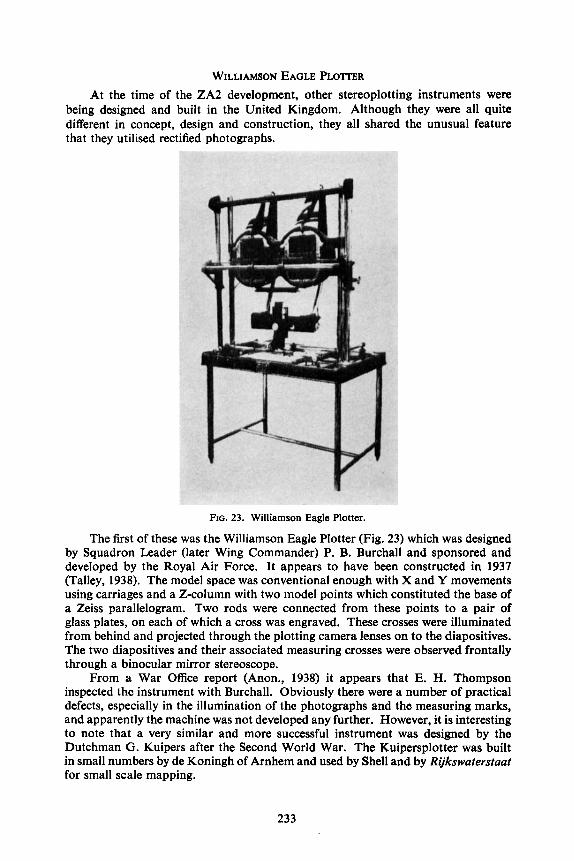
The first of these was the Williamson Eagle Plotter (Fig. 23) which was designed by Squadron Leader (later Wing Commander) P. B. Burchall and sponsored and developed by the Royal Air Force. It appears to have been constructed in 1937 (Talley, 1938). The model space was conventional enough with X and Y movements using carriages and a Z-column with two model points which constituted the base of a Zeiss parallelogram. Two rods were connected from these points to a pair of glass plates, on each of which a cross was engraved. These crosses were illuminated from behind and projected through the plotting camera lenses on to the diapositives. The two diapositives and their associated measuring crosses were observed frontally through a binocular mirror stereoscope.
From a War Office report (Anon., 1938) it appears that E. H. Thompson inspected the instrument with Burchall. Obviously there were a number of practical defects, especially in the illumination of the photographs and the measuring marks, and apparently the machine was not developed any further. However, it is interesting to note that a very similar and more successful instrument was designed by the Dutchman G. Kuipers after the Second World War. The Kuipersplotter was built in small numbers by de Koningh of Arnhem and used by Shell and by Rijkswaterstaat for small scale mapping.
233
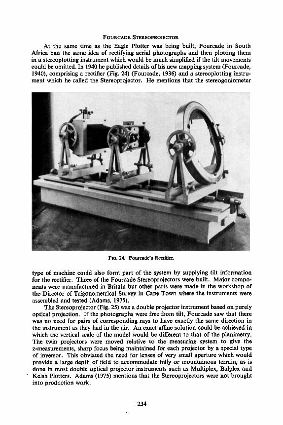
FOURCADE STEREOPROJECTOR At the same time as the Eagle Plotter was being built, Fourcade in South
Africa had the same idea of rectifying aerial photographs and then plotting them in a stereoplotting instrument which would be much simplified if the tilt movements could be omitted. In 1940 he published details of his new mapping system (Fourcade, 1940), comprising a rectifier (Fig. 24) (Fourcade, 1936) and a stereoplotting instru- ment which he called the Stereoprojector. He mentions that the stereogoniometer
Ro. 24. Fourcade’s Rectifier.
type of machine could also form part of the system by supplying tilt information for the rectifier. Three of the Fourcade Stereoprojectors were built. Major compo- nents were manufactured in Britain but other parts were made in the workshop of the Director of Trigonometrical Survey in Cape Town where the instruments were assembled and tested (Adams, 1975).
The Stereoprojector (Fig. 25) was a double projector instrument based on purely optical projection. If the photographs were free from tilt, Fourcade saw that there was no need for pairs of corresponding rays to have exactly the same direction in the instrument as they had in the air. An exact affine solution could be achieved in which the vertical scale of the model would be different to that of the planimetry. The twin projectors were moved relative to the measuring system to give the z-measurements, sharp focus being maintained for each projector by a special type of inversor. This obviated the need for lenses of very small aperture which would provide a large depth of field to accommodate hilly or mountainous terrain, as is done in most double optical projector instruments such as Multiplex, Balplex and Kelsh Plotters. Adams (1975) mentions that the Stereoprojectors were not brought into production work.
234

FIG. 25. Fourcade’s Stereoprojector.
fa) ( b ) FIQ. 26. Thompson’s original sketch of the geometry of the Cambridge Arundel Plotter showing
the situation in (a) the X/Z plane and (b) the Y/Z plane.
235
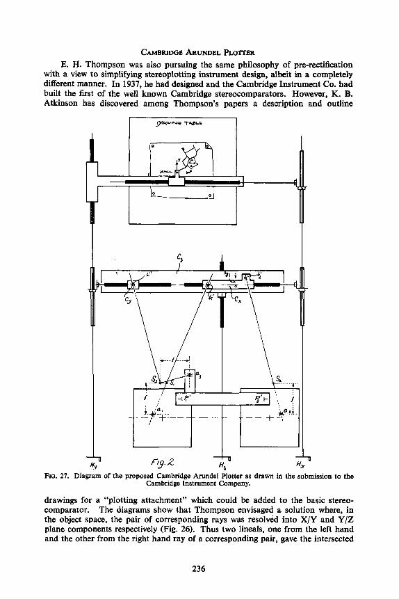
CAMBRIDGE ARUNDEL PLOTTER E. H. Thompson was also pursuing the same philosophy of pre-rectification
with a view to simplifying stereoplotting instrument design, albeit in a completely different manner. In 1937, he had designed and the Cambridge Instrument Co. had built the first of the well known Cambridge stereocomparators. However, K. B. Atkinson has discovered among Thompson’s papers a description and outline
-t
3
FIG. 27. Diagram of the proposed Cambridge Arundel Plotter as drawn in the submission to the Cambridge Instrument Company.
drawings for a “plotting attachment” which could be added to the basic stereo- __ _. - -. . . comparator. The diagrams show that Thompson envisaged a solution where, in the object space, the pair of corresponding rays was resolved into X/Y and Y/Z plane components respectively (Fig. 26). Thus two heals, one from the left hand and the other from the right hand ray of a corresponding pair, gave the intersected
236

position in the X-co-ordinate direction and another lineal the solution in the Y-co-ordinate direction (Fig. 27).
An alternative arrangement (Fig. 28) was also indicated which would allow planimetry only to be plotted from tilted photographs using a second lineal in y to partially overcome the want of correspondence or y-parallax to be found in unrectified photographs. The date of Thompson’s manuscript is 24th January, 1939.
FIG. 28. Diagram of the possible modification to the Arundel Plotter to deal with the y-parallaxes resulting from the use of unrectified photographs.
It was sent to the Cambridge company for comments early in February 1939. The company replied in enthusiastic terms about designing and constructing the proposed instrument. However, no evidence has been found so far that this development did in fact take place and it appears that, with the outbreak of the Second World War shortly afterwards and Thompson’s departure abroad on military duties, the project passed into oblivion.
REFERENCES ADAMS, L. P., 1975. Fourcade. The South African Journal OfPhotogrammetry, 7(1): 4-20. ANON., 1927. The Barr and Stroud Plotting Apparatus. Barr and Stroud Technical Pamphlet No. 386.
I5 pagesf 12 figures. ANON., 1938. Report on the “Eagle” Plotter. 4 pages. (This typewritten report was almost certainly
written by Major (later Major-General) R. LI. Brown.) ANON., 1939. Specification and brief description of the Barr and Stroud Stereogoniometer and Plotter
Type ZA2 and Plotting Board Type HB9. Barr and Stroud Technical Pamphlet No. 863. 10 pagesf4 figures.
DAWE, H. G., 1974. A relative orientation. Photogrammetric Record, 8(43): 27-36. FOURCADE, H. G., 1903. On a stereoscopic method of photographic surveying. Transactions of the
South African Philosophical Society, 141): 1-8. Also published in Nature, 66(1701): 139-141 in 1902.
237

FOURCADE, H. G., 1926, 1928 and 1929. A new method of aerial surveying. Transactions of the
FOURCADE, H. G., 1936. The rectification of air photographs. Empire Survey Review, 3( 19): 272-277. FOURCADE, H. G., 1940. A projection method of mapping from air photographs. Ibid., 5(36):
270-274. HOTINE, M., 1930. The application of stereoscopic photography to mapping. The Geographical
Journal, 732): 144-166. HOTINE, M., 1931. The Fourcade Stereogoniometer. ProfessionalPapers of the Air Survey Committee,
No. 7. H.M.S.O.. London. 159 pages. JENNEY, R. C. N., 1955. The use of air photographs for Ordnance Survey large scale mapping.
Proceedings of the Conference of Commonwealth Survey Oficers, 1951. H.M.S.O., London. 257 pages: 219-233.
MACLEOD, M. N., 1923. Recent developments of air photography: the adjustment of air photo- graphs to surveyed points. The Geographical Journal, 61(6): 413-419.
MACLEOD, M. N., 1939. Some recent developments in British surveying instruments. Proceedings of the Physical Society, 51(4): 710-732.
MATTHEWS, A. E. H., 1976. Revision of 1 : 2500 scale topographic maps. Photogrammetric Record, 8(48): 794-805.
TALLEY, B. B., 1938. Engineering applications of aerial and terrestrial photogrammetry. Pitman, New York and Chicago. 612 pages. (See especially in Chapter 19, pages 529-542, the section entitled “Photogrammetry in the British Empire”.)
THOMPSON, E. H., 1936. An automatic plotting machine for use with air photographs. Proceedings of the Conference of Empire Survey Oficers, 1935. H.M.S.O., London. 371 pages: 127-138.
THOMPSON, E. H., 1938. Air Survey Committee Research Oficers’ Report. War Office. Unpublished. 14 pages.
THOMPSON, E. H., 1973. The Vivian Thompson Stereo-planigraph. Photogrammetric Record, 8(43):
THOMPSON, F. V., 1908. Stereo-photo surveying. The Geographical Journal, 31(5): 534-551.
Royal Society of South Africa, 14(1926): 93-112; 16(1928): 1-11; 17(1929): 237-246.
81-86.
RPsumC On fait l’histoire du restituteur analogique en Grande Bretagne, depuis
ses balbutiements (F. V. Thompson 1907-1908), jusqu’aux annkes 60. On dkcrit en particulier les appareils conGus dans les annkes 20 et 30, en tenant compte d’une masse d’informations inconnues a ce jour tirkes des archives de M. Barr et Stroud, et de celles de feu le professeur Thompson. Puis on passe a ceux qui ont ktd produits pendant et apres la guerre, en s’attachant surtout ci ceux qui sont moins connus parce que n’ayant pas ktk produits en skrie. Ce sont les idkes et projets de Deville, F. V. Thompson, Fourcade et E. H. Thompson qui ont domink cette phiode, et le fi l qui les relie reste trks perceptible.
Zusarnmenfassung Es wird ein Uberblick und eine Analyse iiber den Entwurf und die
Konstruktion von Stereoauswertegeraten im Vereinigten Konigreich gegeben, wobei der Autor, beginnend mit den ersten Geraten von F. V. Thompson aus den Jahren 1907 und 1908 alle bekannten Entwiirfe bis Ende der 60iger Jahre behandelt. Im 1. Teil werden die Gerate der 20iger und 30iger Jahre besch- rieben, wobei vie1 neue Informationen aus dem Archiv der Firma Barr und Stroud und den Beitragen des verstorbenen Professor E. H. Thompson entstammen. Im 2. Teil werden die wahrend des 2. Weltkrieges und danach produzierten Gerate diskutiert, wobeisolche hervorgehoben werden, die weniger bekannt wurden als die in grossen Stiickzahlen produzierten. Die Ideen und Entwiirfe von Deville, F. V. Thompson, Fourcade, E. H. Thompson hatten einen bedeutenden EinpUss wahrend dieser Zeit, und es kann eine starke kontinuierliche Verbindung zwischen ihnen aufgezeigt werden.
It is intended that the second part of this paper will be published in The Photo- grammetric Record, 9(5 1).
238