is democracy more peaceful than other forms of government?
TRANSCRIPT
Ministry of Defence
Defence Standard
00-42(Part 2)/Issue 1 1 September 1997
RELIABILITY AND MAINTAINABILITYASSURANCE GUIDES
PART 2: SOFTWARE

DEF STAN 00-42 (PART 2)/1
AMENDMENTS ISSUED SINCE PUBLICATION
AMENDMENT NUMBER DATE OF ISSUE TEXT AFFECTED SIGNATURE & DATE
Revision Note
Historical Record
Arrangement of Defence Standard 00-42
The proposed arrangement of the complete series of Parts of Defence Standard 00-42 is:
Part 1- One-Shot Devices and One-Shot Systems
Part 2- Software
NOTE: Other Parts may be added to Defence Standard 00-42 as required.

DEF STAN 00-42 (PART 2)/1
RELIABILITY AND MAINTAINABILITY ASSURANCE GUIDES
PART 2: SOFTWARE RELIABILITY
PREFACE
i This Standard provides guidance on accommodating Ministry of Defence (MOD) reliabilitypractices, procedures and requirements in the design process.
ii This Part of the Standard addresses the achievement of software reliability.
iii This Part of the Standard has been prepared by the Committee for Defence EquipmentReliability and Maintainability (CODERM). It reflects the conclusions of consultationsamong various authorities within the MOD and within industry.
iv This Standard has been agreed by the authorities concerned with its use and is intended tobe used whenever relevant in all future designs, contracts, orders etc and whenever practicableby amendment to those already in existence. If any difficulty arises which preventsapplication of this Defence Standard, the Directorate of Standardization shall be informed sothat a remedy may be sought.
v Any enquiries regarding this Standard in relation to an invitation to tender or a contract inwhich it is incorporated are to be addressed to the responsible technical or supervisingauthority named in the invitation to tender or contract.
vi This Standard has been devised for the use of the Crown and its contractors in theexecution of contracts for the Crown. The Crown hereby excludes all liability (other thanliability for death or personal injury) whatsoever and howsoever arising (including, butwithout limitation, negligence on the part of the Crown its servants or agents) for any loss ordamage however caused where the Standard is used for any other purpose.
1
DEF STAN 00-42 (PART 2)/1
CONTENTS PAGE
Preface 1
Section One. General
0 Introduction 31 Scope 42 WARNING 43 Related Documents 54 Definitions 6
Section Two. Principles of the Software Reliability Plan and the Software Reliability Case
5 Introduction to the Plan and the Case 96 Principles of the Software Reliability Plan 97 Principles of the Software Reliability Case 10
Section Three. Production and Assessment of the Software Reliability Plan and the SoftwareReliability Case
8 Introduction to Section 139 Software Reliability Planning 1310 The Software Reliability Case 1511 COTs Software 2112 ASICs 2213 Safety Critical Software 22
Figure 1Figure 2Figure 3
Table A
Annex AAnnex BAnnex CAnnex DAnnex EAnnex FAnnex GAnnex HAnnex J
Elements of a Reliability ArgumentTransitions to a Software Failure StateApparent Size of Software Fault
Subjective Requirement Evaluation
Table of Methods and TechniquesAllocation of Reliability to SoftwareSoftware MaintainabilityDesign ReviewsSoftware Requirements EngineeringSoftware Design and ImplementationEvaluation of ReliabilityASICsBibliography
1516F-8
E-8
A-1B-1C-1D-1E-1F-1G-1H-1J - 1
2

DEF STAN 00-42 (PART 2)/1
RELIABILITY AND MAINTAINABILITYASSURANCE GUIDES
PART 2: SOFTWARE RELIABILITY
Section One. General
0 Introduction
0.1 Def Stan 00-40 implements Allied Reliability and Maintainability Publication (ARMP- 1)and lists specific R&M tasks which form part of the design and development programme.The requirements of Def Stan 00-40, in whole or in part, can be made contractual during thedesign and development stages.
0.2 Def Stan 00-41: MOD Guide to Practices and Procedures describes the ARMP- 1 tasks ingreater detail and adds supplementary material regarding tasks not listed in ARMP- 1.
0.3 Def Stan 00-42 is grouped under the general title of “Assurance Guides” and providesfurther guidance on MOD reliability practices, procedures and requirements in the designprocess.
0.4 This Part of Def Stan 00-42 is concerned with software, including ASICs and COTSsoftware. It provides guidance beyond Def Stan 00-41 on the practices and procedures thatshould be adopted for assuring that any system that contains software achieves its requiredreliability. It aims to support the needs of Contractors, MOD Project Managers and EndUsers.
0.5 In respect of software maintainability, guidance maybe obtained by reference to Def Stan00-60 Part 3: Logistic Support Analysis for Software. The latter expresses MOD policy forthe maintenance and support of software and describes the factors that affect the supportabilityof software products, including elements in the development process.
0.6 The philosophy embraced is one of improving system reliability by early defect removaland continued defect prevention through the software development life-cycle. Visibility ofreliability achievement is enforced through critical examination of the intellectual products ofdevelopment. Because of extreme difficulties in making quantitative predictions for softwarereliability, credence is given to indirect measurements and assessments of correctness. Directmeasures of software reliability achievement are made during full system testing, or based onanalysis or field experience. Additionally this Standard enables and seeks to encourage thedevelopment and application of new techniques to assist with evaluation throughout thesoftware life-cycle.
0.7 The guidance is built around two key components: the Software Reliability Plan and theSoftware Reliability Case. The plan addresses the software aspects of the system reliabilityplan, and describes the activities that are to be undertaken to achieve and demonstrate
3

DEF STAN 00-42 (PART 2)/1
0.7 (Contd)
software reliability. The case provides a justification of the approach, and during the project itdocuments the evidence that verifies that the software meets the reliability requirements.
0.8 The guide makes an important distinction between achievement and evaluation ofsoftware reliability. The Contractor should apply a software engineering process that gives agood likelihood of achieving software reliability requirements. However, the process useddoes not ensure that reliability requirements will be met for particular software products, andtherefore the Contractor should evaluate the reliability of the evolving software products ateach development phase.
0.9 The concept of the plan and case should enable innovation, and therefore the guideattempts to be general, with no preference for specific methodologies. However, abibliography of appropriate standards and technical references is provided.
0.10 The guide is structured as follows. Section Two provides a summary of the principles ofthe plan and case, and is intended particularly for project managers. Section Three providesguidance on the plan and the case for the Procurer’s and Contractor’s technical staff. Detailedtechnical material is contained in the annexes.
1 Scope
1.1 This Standard provides a framework for the management of software reliability withinsystem reliability requirements, based around the Software Reliability Plan and SoftwareReliability Case. It emphasizes the importance of evaluating progress towards meetingsoftware reliability requirements throughout the project life-cycle.
1.2 This Standard applies to all projects that incorporate software, including the integration ofpreviously developed software and COTS software products as well as bespoke developments.This Standard applies to conventional employment of software and to software associatedwith ASICs and programmable hardware.
1.3 This Standard does not describe software development practices in detail. However,references are provided to standards and other sources of further information.
2 WARNING
This Defence Standard embodies procedures, techniques, practices and tools which whenfollowed or used correctly will reduce but not necessarily eliminate the probability that theproduct will contain faults which are attributable to software. The standard in no wayabsolves either the designer, the producer, the supplier or the user from statutory and all otherlegal obligations relating to health and safety at any stage.
4

DEF STAN 00-42 (PART 2)/1
3 Related Documents
3.1 The following documents and publications are referred to in this Standard:
ANSI/IEEE 610.12BS 5760 (Part 8)
Def Stan 00-13
Def Stan 00-40 (Part 2)(ARMP-2)Def Stan 00-41
Def Stan 00-44
Def Stan 00-49
Def Stan 00-55
Def Stan 00-56Def Stan 00-60 (Part 3)
Def Stan 05-91
Def Stan 05-95
Glossary of Software Engineering TerminologyGuide to Assessment of Reliability of Systems ContainingSoftwareRequirements for the Achievement of Testability in Electronicand Allied EquipmentReliability and Maintainability.Part 2: General Application Guidance on the Use of Part 1Reliability and Maintainability, MOD Guide to Practices andProceduresReliability and Maintainability Data Collection andClassificationReliability and Maintainability, MOD guide to TerminologyDefinitionsRequirements for Safety Related Software in DefenceEquipmentSafety Management Requirements for Defence SystemsIntegrated Logistic Support.Part 3: Guidance for Application of Software supportQuality System Requirements for Design/Development,Production, Installation and Servicing.Quality System Requirements for the Design/Development,Supply and Maintenance of software
3.2 Reference in this Part of the Standard to any related documents means, in any invitationto tender or contract, the edition and all amendments current at the date of such tender orcontract unless a specific edition is indicated.
3.3 Related documents may be obtained from:
DOCUMENT SOURCE
Allied Reliability and Directorate of Standardization (Stan 2)Maintainability Publication Kentigern House(ARMP) 65 Brown Street
Glasgow G2 8EX
British Standards (BS) British Standards InstitutionSales Department389 Chiswick High RoadLondon W4 4AL
5

DEF STAN 00-42 (PART 2)/1
3.3 (Contd)
DOCUMENT SOURCE
Defence Standards (Def Stan) Directorate of Standardization (Stan 1)Kentigern House65 Brown StreetGlasgow G2 8EX
American National Standards Technical IndexesInstitute (ANSI)/Institute of Willoughby RoadElectrical & Electronics Engineers Bracknell(IEEE) Berks RG12 4DW
3.4 A bibliography of publications containing further technical information on the methodsand techniques discussed in this Standard is provided at Annex J.
4 Definitions
4.1 The following special terms are used in this Part of the Standard. The definition of termsnot given below should follow Def Stan 00-49 and ANSI/IEEE 610.12 where possible;otherwise normal English usage should be assumed.
4.2 Animation. The process by which the behaviour defined by a formal method or otherspecification notation is examined and validated against the informal requirements.
4.3 ASIC. Application-Specific Integrated Circuit.
4.4 BIT. Built-in-test. Used in this Standard to refer to the use of software for automaticfault detection and fault isolation. See also Def Stan 00-13.
4.5 Controlled failure. A failure that is handled by entering some defined degraded or failsafe state. The ability to control failures depends on the fail soft or fail safe strategy of thedesign and the nature of the application. See also Figure 2.
4.6 COTS software. Commercial off-the-shelf software, ie commercial software that is usedwithout modification (apart from configuration) in the system.
4.7 Derived requirements. Software requirements that evolve during the course of thesoftware development life-cycle. Examples are failure reporting and handling requirementsfollowing from the decision to write defensive code; and specific timing and capacityrequirements resulting from the choice of a particular microprocessor and memory unit.
6

DEF STAN 00-42 (PART 2)/1
4.8 Design Review. A formal review of a software development project, including thesoftware design and the Software Reliability Case, to establish that the software meets itsrequirements, including reliability requirements.
4.9 Error. A system state, resulting from a fault or human mistake, that is liable to lead to afailure if the error is not detected and corrected.
4.10 Error recovery. The correction of an error before it results in a failure, enabling thesoftware to make a transition back to correct operation or to a defined state. Error recoverydepends on the effectiveness of the error detection and recovery measures in the design (seeFigure 2).
4.11 Failure. The inability of software to fulfil its operational requirements.
4.12 Fault. An imperfection or deficiency in the software that may, under some operationalconditions, contribute to a failure.
4.13 Fault activation. The transition to an error from correct operation (see Figure 2). Theprobability of this transition depends on the number of faults and their size and distributionrelative to the inputs to the software (which will depend on the way it is used), and isaddressed by fault avoidance measures during development.
4.14 Formal method. A software specification and development method, based on amathematical system, that comprises: a collection of mathematical notations addressing thespecification, design and development phases of software production; a well-founded logicalinference system in which formal verification proofs and proofs of other properties can beformulated; and a methodological framework within which software may be developed fromthe specification in a formally verifiable manner.
4.15 Procurement Specification. The most detailed specification of the system produced bythe Purchaser’s organisation, and the basis for the contract with the Contractor. Developedfrom the Cardinal Points Specification and the Staff Requirement, possibly with the aid of afeasibility study.
4.16 Requirements engineering. The activities that lead to the production of the Purchaser’srequirements, including requirements capture, definition, analysis and the development ofderived requirements.
4.17 Software component. One of the parts that make up a software system. A softwarecomponent may be a module, a unit or a larger structure depending on the stage ofdevelopment.
4.18 Software fault density. The number of faults in a given amount of software. Faults perthousand non-blank, non-comment lines of code is a common measure.
7
DEF STAN 00-42 (PART 2)/1
4.19 Software product. All the manifestations of software that exist at a particular phase inthe development life-cycle, such as specifications, designs, source code and executable code.
4.20 Software engineering process. The application of technical and managerial methods,techniques and tools by a team of people to produce a software product from the Purchaser’srequirements. Elements of the software engineering process may include specification,design, coding, testing and reviewing.
4.21 Statistical testing. Testing using data representative of the actual operating environment,to an extent that gives a statistical estimate of reliability. Statistical testing will probably becarried out at the system level.
4.22 Uncontrolled failure. A failure where no error recovery or controlled failure is carriedout. The impact of this will depend on the criticality of the system functions affected (seeFigure 2).
4.23 V&V. Verification and validation. ANSI/IEEE 610.12 provides further information.
8
DEF STAN 00-42 (PART 2)/1
Section Two. Principles of the Software Reliability Plan and the Software Reliability Case
5 Introduction to the Plan and the Case
5.1 The Software Reliability Plan and the Software Reliability Case are the two keydocuments supporting the achievement of software reliability. The plan addresses thesoftware-specific management and technical tasks that are to take place within the overallreliability programme, including collecting evidence of reliability achievement, andmaintaining the case. The case develops during the project and documents the evidence andarguments for software reliability achievement. It also contains a justification of the softwareengineering process and the software architecture.
5.2 The Purchaser may require the Software Reliability Plan and the Software ReliabilityCase as deliverable items in the contract. Also, the Purchaser may require a plan and a tender-stage case at the tender or pre-contract stages of the project. Further issues of the case shouldtake place at project milestones and may be linked to the payment plan.
5.3 Guidance on developing the Software Reliability Plan and the Software Reliability Caseis contained in Section Three.
6 Principles of the Software Reliability Plan
6.1 The Software Reliability Plan is the plan for the management and technical activities thatbear on the achievement of software reliability, including the maintenance and updating of theSoftware Reliability Case. It should be traceable to system reliability planning and to avoidunnecessary replication, should be integrated with software development and qualitymanagement planning.
6.2 The Software Reliability Plan should describe:
(a) The software reliability requirements, derived from the system reliability requirements;
(b) The software engineering process, addressing:
(i) the development life-cycle, including: its constituent processes and tasks; the relationshipbetween the tasks in terms of their inputs, outputs and scheduling; planned completion dates;and dependencies on other products and activities;
(ii) the techniques to be used for software requirements analysis and review;
(iii) the techniques, methods and tools to be used for software production, verification andvalidation at each life-cycle phase;
(iv) any support tools to be used, including automated configuration management anddatabase support for records and data;
9

DEF STAN 00-42 (PART 2)/1
6.2 (Contd)
(v) the documented procedures to be used, including the Contractor’s in-house procedures,national and international standards;
(vi) the identification, selection and integration of COTS and previously developed software.
(c) The techniques, methods and tools to be used for the evaluation of the achieved softwarereliability at each life-cycle phase;
(d) Project risk analysis for the software;
(e) The organisational structure, including:
(i) the individuals and organisations involved in software development, includingsubcontractors;
(ii) the identification of key posts, with a description of minimum levels of competence;
(iii) the means by which all staff, including subcontractors, are made aware of the softwarereliability requirements and their specific responsibilities;
(iv) any training activities and requirements.
(f) The procedures for software reliability progress reporting, including:
(i) the phased updating of the Software Reliability Case;
(ii) the phasing of Design Reviews.
(g) other documentation and data to be delivered.
6.3 The plan should make reference to the Statement of Work for the software development,containing details of the manpower and resource requirements, and how they are to be met.
7 Principles of the Software Reliability Case
7.1 The Software Reliability Case should be a readable overview of the evidence that thesoftware meets its reliability requirements, with references to project development records andthe results of analyses of software components as appropriate. The case is more than proofthat the plan has been executed as it provides evidence about intellectual products. Thisevidence should address the direct evaluation of the reliability of the software products (egfrom reliability tests and trials and analysis of the design), and also the suitability of thesoftware architecture and the software engineering process.
10

DEF STAN 00-42 (PART 2)/1
7.2 The case should be a living document and its development should proceed through anumber of stages of increasing detail during the project. At the beginning of a project itshould provide confidence, before committing significant resources, that there is minimal riskof failing to meet the reliability requirements; during the development stage it should provideconfidence that the reliability requirements are being met by the software products; and duringuse of the system it should provide confidence that the software is reliable and continues to beso as the result of any maintenance.
7.3 The development of the Software Reliability Case takes place in identifiable phases:
(a) Tender-stage Software Reliability Case; which can form part of any proposal in order tojustify design and process decisions upon which the proposal is based.
(b) Development-stage Software Reliability Case; which can be a contracted deliverable,phased as appropriate.
(c) In-service Software Reliability Case; which can be a contracted deliverable, considered atan early stage or negotiated at a later date.
7.4 Tender-stage Software Reliability Case
7.4.1 The Tender-stage Software Reliability Case should provide an overview and analysis ofthe Contractor’s approach to reliability achievement. It should give confidence that:
(a) the Contractor is capable of supplying software that is commensurate with the reliabilityrequirements of the proposed system;
(b) the plan is appropriate for the reliability requirements of the proposed system;
(c) the software architecture is appropriate for the reliability requirements of the proposedsystem;
(d) the Contractor will be able to demonstrate reliability achievement during the project.
7.5 Development-stage Software Reliability Case
7.5.1 During development, the Contractor should update the case with a summary andappraisal of the results of the activities that contribute to the reliability evaluation. By thetime of acceptance into service, the case should contain the complete set of evidence that thereliability requirements of the software have been met.
7.5.2 The Purchaser and the Contractor should agree in advance the measurements, includingreliability tests and trials, to be taken of the software products and the software engineeringprocess to provide evidence that the development is proceeding satisfactorily. Thesemeasurements should be described in the case; earlier versions of the case should predict
11

DEF STAN 00-42 (PART 2)/1
7.5.2 (Contd)
values for these measurements that the Purchaser can compare to the results actually obtainedlater in the life-cycle.
7.5.3 Issues of the case should be planned for appropriate milestones in the softwaredevelopment life-cycle, for instance after reliability tests and trials. The current version of thecase should be presented at each Design Review (see Annex D), and the outcome included inthe case.
7.6 In-service Software Reliability Case
7.6.1 The Purchaser should consider employing in-service software reliability management.This includes the collection of operational and usage data and the maintenance of an In-service Software Reliability Case. The case should contain a description of the fieldexperience with the software or any part of it, and an analysis of the impact of any softwarefailures on the reliability of the system, addressing the potential consequences of the failure,its root causes, and the lessons for the software engineering process.
7.6.2 An In-service Case can be justified when reliability remains uncertain after a decision toemploy the software in question, either because of continuing development or inadequateevidence of reliability achievement during development.
7.6.3 In-service reliability data can be used for:
(a) reviewing or confirming reliability achievement;
(b) determining reliability when software is used in a new environment;
(c) gathering experience on the performance of particular methods, techniques and processesfor the benefit of future projects and development organisations which operate within aprocess improvement framework.
7.6.4 Options for employing an In-service Software Reliability Case, includingresponsibilities and procedures for managing reliability data should be considered duringcontract negotiations.
12
DEF STAN 00-42 (PART 2)/1
Section Three. Production and Assessment of the Software Reliability Plan and SoftwareReliability Case
8 Introduction to Section
8.1 This section provides general guidance aimed at the production and assessment of theSoftware Reliability Plan and Software Reliability Case. More detailed technical informationis contained in the annexes. An index to the specific methods and techniques described in theannexes is provided at Annex A, with a summary of how each method and techniquecontributes to the case. A bibliography of reference material is provided at Annex J.
8.2 The Contractor should ensure that the Software Reliability Plan and Software ReliabilityCase are integral parts of the software design and development methodology, and shouldevaluate at the tender stage the feasibility and cost of implementing the plan and maintainingthe case.
8.3 The software should be designed to facilitate production of the Software Reliability Case.Both the achievement and demonstration of software reliability should be design drivers. Thisshould help to avoid delays and additional costs for the Contractor due to software reliabilityproblems.
9 Software Reliability Planning
9.1 The Software Reliability Plan
Planning for software reliability should be an integral part of project planning. Therefore theSoftware Reliability Plan may be integrated with the software development plan and/or thesoftware quality plan, provided that the measures to achieve and evaluate software reliabilityare easily distinguishable. Traceability should be provided between the plan and the overallReliability Programme Plan.
9.2 Software reliability planning activities
9.2.1 Software reliability planning should, as a minimum, include the following activities:
(a)
(b)
(c)
allocating reliability requirements to software;
defining the strategy for software reliability achievement;
defining the strategy for evaluating achieved software reliability.
These activities are not sequential, but are interlinked and iterative.
9.2.2 An adequate software engineering process is necessary but not sufficient for theachievement of software reliability. A defined process is necessary to ensure that appropriatemethods and techniques are carried out at the correct point in the development, to enforce
13

DEF STAN 00-42 (PART 2)/1
9.2.2 (Contd)
configuration control, and to enable adequate management of the project. However, theprocess does not in itself allow predictions or demonstrations of software reliability to bemade. Software reliability evaluation, to provide assurance that the software products as builtmeet their reliability requirements, should be planned for as a specific activity.
9.3 Allocation of reliability requirements to software
9.3.1 Software components may be identified at various levels in a system breakdown, andmay be implemented in a number of ways, including application software, firmware, COTSand ASICs The Contractor should allocate system reliability requirements to the softwarecomponents as an initial step in software reliability planning. This enables activities to beplanned on the basis of their ability to achieve and demonstrate the specific softwarereliability requirements.
9.3.2 More detailed guidance on software reliability allocation is contained in Annex B.
9.4 Strategy for software reliability achievement
The Contractor should plan a software engineering process that gives a good likelihood thatthe developed software will meet its reliability requirements. The plan should include:
(a) software requirements engineering to ensure that the needs of the Procurer are fullyunderstood (see Annex E);
(b) the application of appropriate techniques and methods for software specification, designand implementation, selected on the basis of the reliability requirements and the Contractor’sexperience (see Annex F);
(c) any detailed planning activities that should take place prior to application of each methodor technique;
(d) development and review of test plans at the software specification phase.
9.5 Evaluation of achieved software reliability
9.5.1 The Contractor should plan to provide direct evidence of the reliability of thedeveloping software products throughout the project.
9.5.2 As explained in Annex G, direct evidence of software reliability can come from:
(a) testing;
(b) field data;
1 4

DEF STAN 00-42 (PART 2)/1
9.5.2 (Contd)
(c) fault data;
(d) analytical arguments,
9.5.3 In general, different types of evidence will be used to address different aspects of thereliability requirements for the software. Reliability evaluation of software with stringentreliability requirements is especially difficult and in this case the Contractor should plan toprovide diverse forms of evidence to cover each aspect of software reliability. The finalarbiter will be testing at system level.
10 The Software Reliability Case
This clause provides guidance on the way the Software Reliability Case should be structuredand linked to the fault avoidance and fault tolerance strategy of the plan, the way in whichreliability demonstration should be documented, and on the contents of the case at the tender,development, and in-service stages.
10.1 Structuring the Software Reliability Case
10.1.1 A Software Reliability Case is an assembled rationale which would be convincing to athird party and primarily consists of the following elements:
(a) a claim, about a property of the software;
(b) evidence and assumptions, which are used to support the reliability claim (see 9.5);
(c) an argument linking the evidence to the claim.
This structure is illustrated in Figure 1
arguments
Figure 1 Elements of a Reliability Argument
15

DEF STAN 00-42 (PART 2)/1
10.1.2 As an example, a claim could be a statement that a software component meets itsallocated reliability target; the evidence could come from testing; and the argument could bebased on statistical analysis.
10.1.3 The case will normally be presented as a hierarchical structure, with top-level claimsdecomposed into sub-claims appropriate for the architecture of the system and software. Thisstructure should evolve over the lifetime of the project. Initially some of the sub-claims willbe design targets, but as the system develops, the sub-claims will be replaced by facts or moredetailed arguments based on the actual implementation. Deviations from earlier versions ofthe case should be analysed for their impact on the claims and sub-claims.
10.2 Strategy for fault avoidance and fault tolerance
10.2.1 The Contractor should develop a strategy for minimizing software faults, and forcontrolling system failures due to any residual software faults.
10.2.2 Figure 2 is one way of illustrating the transitions that may occur between correctlyfunctioning software and a failure state. The overall reliability of the software will depend onthe probability of each of these transitions, and the case should describe how each is to beaddressed. Different transitions may be controlled in different ways and given differentemphasis; for example, in one application the emphasis could be on error recovery by meansof fault-tolerant architectures, whereas in another the concentration might be on erroravoidance by means of structured design methods and static analysis. Different components(eg COTS and bespoke software) may also be treated differently.
Figure 2 Transitions to a Software Failure State
16

DEF STAN 00-42 (PART 2)/1
10.3 Demonstration of software reliability achievement
10.3.1 Demonstration of software reliability achievement is a key part of the case and isobtained from two sorts of evidence:
(a) direct evaluation of the achieved reliability of the software products;
(b) evidence of the general suitability of the software engineering process.
This evidence should be documented in the case as it is accumulated.
10.3.2 Direct evaluation of achieved software reliability. The case should address theplanned means for the direct evaluation of the reliability of the software products, as describedin 9.5. It should provide:
(a) An overview of the reliability evaluation tasks, explaining how they demonstrate that thereliability requirements have been met, and describing how evidence of reliabilityachievement can be accumulated during the project. This should include as appropriate:
(i) the feasibility of collecting sufficient quantities and quality of data for reliabilityevaluation from reliability growth modelling, fault data and/or field experience;
(ii) the resources needed for statistical testing, and the feasibility of providing justifiableoperational profiles for the system taking into account the uncertainties of equipmentdeployment;
(iii) a description of the approaches to be used for providing analytical arguments, and anassessment of their feasibility in view of the estimated software size.
(b) A structured summary and overview of the evidence as it is collected during the project,with reference to detailed results as appropriate. This may include:
(i) evidence from testing, including reliability growth modelling, statistical testing, data fromtests and trials, and performance testing, with an assessment of its accuracy and relevance tooperational use;
(ii) a description of any claims made on the basis of previous in-service experience, includingan analysis of the similarities and differences between the actual system and environment andthose to which the experience relates;
(iii) evidence from fault data on the software;
(iv) the results of any analytic arguments deployed to show the absence of certain faults, andthe assumptions on which they are based.
17

DEF STAN 00-42 (PART 2)/1
10.3.2 (Contd)
(v) an overview of any ASICs COTS or previously developed software that is to be used, anda description of the way in which it will contribute to software reliability, taking into accountany changes in operating environment and use profile (see 11 and 12).
Technical guidance on software reliability evaluation is given in Annex G.
10.3.3 General suitability of the software engineering process. The case should contain anoverview of the software engineering process that explains how it is appropriate for thereliability requirements for the software (see 9.4). Items that might be included are:
(a) An analysis of the methods, techniques and procedures to be used, with an assessment oftheir suitability for the reliability requirements, including:
(i) a description of the generic types of software fault that will be specifically addressed andminimized;
(ii) an analysis of reliability data on other software developed using the proposed or similarmethods, techniques and processes (sources of these data include the Contractor’s ownrecords and the published literature);
(iii) a justification of the choice of tools and support software, with a description of the wayin which known problems (eg compiler faults) are to be handled and recorded.
(b) A description of how reliability progress is to be measured. This should include:
(i) any measurements that are to be taken (eg as part of inspections) during the softwaredevelopment life-cycle of the performance of the software engineering process (suitablemeasures are discussed in Annex F);
(ii) the verification and validation test strategy, including the test coverage to be achieved andthe means for generating the tests.
The case should include acceptance criteria for these measures, based on previous experiencewith the software engineering process. During development, these data should be recorded inthe case and compared with the acceptance criteria. The corrective action to be taken if theacceptance criteria are not met should be described.
(c) Confirmation that the minimum levels of personnel competency defined in the plan havebeen achieved.
18

DEF STAN 00-42 (PART 2)/1
10.4 Tender-stage Software Reliability Case
10.4.1 The Tender-stage Software Reliability Case provides an overview and analysis of theContractor’s approach to reliability achievement and evaluation at the pre-contract or tenderstage. Items that might be included are:
(a) A description of software at an appropriate level of detail, including the main functions,the consequences of failure, and the environment in which it will be used.
(b) A description of the proposed software architecture and the way in which it is appropriateto system reliability requirements, including:
(i) the allocation of reliability to the software components (see Annex B);
(ii) the design strategy for fault avoidance and fault tolerance (eg for internal errors, externalfailures and overload conditions) adopted to meet the reliability requirements (see 10.2), withan overview of the trade-offs made and any architectures that were considered but rejected;
(iii) the role of the software in achieving system reliability (eg by implementing BITfunctions - see Def Stan 00-13);
(iv) any hardware monitoring of the software (eg by means of watchdogs), with a discussionof the coverage of failures;
(v) the means used to prevent failures propagating (eg software partitioning, hardwarememory protection, etc.).
(c) An overview of the software engineering process, as described in 10.3.3.
(d) A description and explanation of the way in which software reliability evaluation is to becarried out through the life-cycle, as described in 10.3.2(a).
(e) As part of project risk analysis, an assessment of any specific risks associated withmeeting the software reliability requirements within the project timescales and budget, wherepossible by reference to similar systems.
10.5 Development-stage Software Reliability Case
10.5.1 During the development stage, the case should accumulate the evidence that reliabilityachievement is proceeding satisfactorily. This evidence should include activities carried outearly in the development, such as inspections of specifications and analysis of designs forperformance attributes, as well as those carried out later, such as testing on a simulator. Thecase may include:
(a) Data about the development, such as fault density measures and the results of inspectionsof specifications, designs and code (see Annex F). The way in which this evidence shows that
19

DEF STAN 00-42 (PART 2)/1
10.5.1 (Contd)
the development is likely to meet its reliability requirements should be described. Earlierversions of the case should predict values for these data; later versions should compare thepredictions with the actual evidence, discuss the reasons for any differences and proposechanges to improve the accuracy of the predictions.
(b) Data on the evaluation of achieved reliability as described in 10.3.2(b). An assessment ofthe sensitivity of the overall software reliability evaluation to the individual pieces of evidenceshould be included.
(c) A statement of the software components (including specifications, design documents andsoftware code) developed so far.
(d) A summary of changes from previous versions of the case with a statement of the reasonfor the change and an analysis of the significance and implications for software reliability.
(e) A description of any outstanding issues that may effect the reliability of the software, anda statement of progress with respect to the Software Reliability Plan.
(f) An analysis of the compliance with this Standard and any other standards or guidelinesreferenced in the Software Reliability Plan. A statement of any concessions that have beennegotiated with the MOD Project Manager should be included.
(g) The software configuration and versions of hardware, tools and support software that thiscase refers to, defined by reference to the Software Configuration Management Plan.
(h) The outcome of the presentation of the case at the Design Reviews (see Annex D).
10.5.2 Amendments to the software requirements may have an impact on software reliabilityachievement. The case should state how the reliability requirements will continue to be metfollowing such amendments, and describe any changes to the plan and case that are necessary.
10.6 In-service Software Reliability Case
10.6.1 In-service software reliability management includes the collection of operational andusage data and the maintenance of an In-service Software Reliability Case.
10.6.2 Data collection should be by an agreed means of in-service reporting mechanism. DefStan 00-44 contains guidance on data reporting and classification; Part 2 addresses incidentsentencing (see also BS 5760 Part 8).
10.6.3 In-service software reliability management may be supported by mechanisms whichidentify, diagnose and record internal failures. As the inclusion of such features is adevelopment stage activity it is important that the need is given timely consideration. Thedata recorded may include:
20

DEF STAN 00-42 (PART 2)/1
10.6.3 (Contd)
(a)
(b)
(c)
(d)
(e)
clear identification of the current software version and configuration;
utilisation levels of resources;
task execution states;
errors detected at interfaces;
anomalies detected by defensive software checks;
operating modes (eg automatic, manual or degraded);(f)
(g) key input and output data values.
10.6.4 It is important to justify the similarityservice reliability data and any proposed newconsidered may include:
between the applications used to gather in-application (see F.2.13.2). The attributes to be
(a)
(b)
(c)
(d)
(e)
(f)
(g)
(h)
data rates;
throughput;
functions used;
input ranges;
resource usage (eg CPU time);
configuration options (eg data conversion routines and thresholds);
operational mode;
accuracy;
(i) mission time.
11 COTS Software
11.1 Current trends are towards an increased use of commercial off-the-shelf (COTS)software and other forms of pre-existing software that may not have been originally designedfor the Procurer’s use. While this may reduce procurement costs, software reliability planningneeds to address additional problems that may arise in the reliability evaluation of COTS
21

DEF STAN 00-42 (PART 2)/1
11.1 (Contd)
software. COTS software generally is not developed under the umbrella of a particularcontract and there are few reliability targets or incentives to collect or provide informationabout reliability.
11.2 Some COTS may have benefited from reliability growth in service, as discussed inAnnex F. However, commercial pressures to produce frequent upgrades of COTS softwareoften mean that priority is given to providing new features rather than improving reliability.
11.3 One difficulty with COTS software is that it may not be possible to perform detailedtesting or analysis based on knowledge of the design or code. This limitation implies thatmany of the current approaches to software evaluation are not applicable. Examination ofdevelopment procedures, progress reports and test results should not be ruled out but it may bedifficult to make procurement decisions based on the quality of the software productionprocess because there is insufficient information.
11.4 Therefore, evaluation of the reliability of COTS software has generally to be undertakenby treating it is as a black box. Possible means are:
(a) functional testing (see Annex F);
(b) use of field data (see Annex G), taking into account differences in operating environment(see Annex F).
12 ASICs
The Software Reliability Plan and Software Reliability Case should explicitly consider anyASICs (Application-Specific Integrated Circuits) that are to be developed. Guidance onASICs is given in Annex H.
13 Safety Critical Software
Development of safety critical and safety related software requires the development of aSoftware Safety Plan and a Software Safety Case, addressing the specific methods andactivities to be adopted to achieve and evaluate safety. Details are contained in Def Stan00-55 and Def Stan 00-56.
22

DEF STAN 00-42 (PART 2)/1ANNEX A
Table of Methods and Techniques
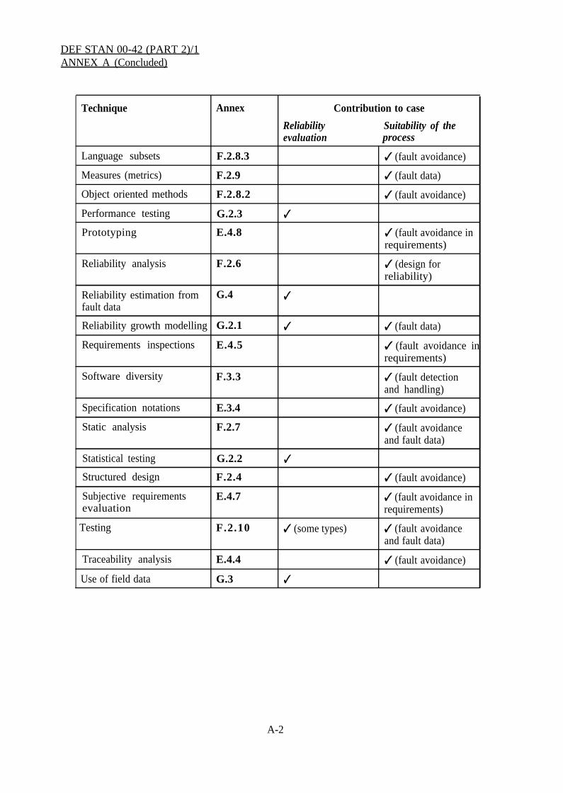
A.1 The annexes to this Standard contain technical guidance on the achievement andevaluation of software reliability. The table below contains an alphabetical index to thespecific methods and techniques that are mentioned. It also indicates how each contributes tothe Software Reliability Case by evaluating reliability and/or demonstrating the suitability ofthe software engineering process. The methods and techniques are described for the purposesof illustration, and the inclusion or omission of a particular method or technique does notindicate a preference by the MOD.
Technique Annex Contribution to case
Reliability Suitability of theevaluation process
Analytical arguments G.5 ✓
Checklists E.4.6 ✓ (fault avoidanceand fault data)
Classification of E.4.3 ✓ (fault avoidance inrequirements requirements)
Cleanroom F.2.11 ✓ ✓ (fault avoidance)
Defensive programming F.3.2 ✓ (fault detectionand handling)
Design maturity F.2.13 ✓ (use ofcomponents ofproven reliability)
Design reviews Annex D ✓ (fault avoidanceand fault data)
Exhaustive testing G.5.3 ✓
Fault tolerance F.3 ✓ (fault detectionand handling)
Fault tolerance verification F.3.4 ✓
Formal methods E.3.5, F.2.5 ✓ (fault avoidanceand fault data)
High level programming F.2.8 ✓ (fault avoidance)languages
Human factors in software F.2.12 ✓ (fault avoidance)design
Inspections F.2.3 ✓ (fault avoidanceand fault data)
Continued on page A-2
A-1
DEF STAN 00-42 (PART 2)/1ANNEX A (Concluded)
Technique Annex Contribution to case
Reliability Suitability of theevaluation process
Language subsets F.2.8.3 ✓ (fault avoidance)
Measures (metrics) F.2.9 ✓ (fault data)
Object oriented methods F.2.8.2 ✓ (fault avoidance)
Performance testing G.2.3 ✓
Prototyping E.4.8 ✓ (fault avoidance inrequirements)
Reliability analysis F.2.6 ✓ (design forreliability)
Reliability estimation from G.4 ✓fault data
Reliability growth modelling G.2.1 ✓ ✓ (fault data)
Requirements inspections E.4.5 ✓ (fault avoidance inrequirements)
Software diversity F.3.3 ✓ (fault detectionand handling)
Specification notations E.3.4 ✓ (fault avoidance)
Static analysis F.2.7 ✓ (fault avoidanceand fault data)
Statistical testing G.2.2 ✓
Structured design F.2.4 ✓ (fault avoidance)
Subjective requirements E.4.7 ✓ (fault avoidance inevaluation requirements)
Testing F.2.10 ✓ (some types) ✓ (fault avoidanceand fault data)
Traceability analysis E.4.4 ✓ (fault avoidance)
Use of field data G.3 ✓
A-2

DEF STAN 00-42 (PART 2)/1ANNEX B
Allocation of Reliability to Software
B.1 Introduction
This annex provides guidance on the allocation of system reliability requirements to software.
B.2 Software Reliability Allocation
B.2.1 Software reliability requirements should be derived from the reliability requirementsfor the system by apportioning reliability to the software components of the system design, inthe same way as to the hardware components, using techniques such as fault tree analysis andreliability block diagrams. Reliability apportionment should be carried out as described inSection Thirteen of Def Stan 00-41.
B.2.2 Measures for software reliability are discussed in BS 5760 Part 8. Where appropriate,separate software reliability requirements should be given for different types andconsequences of failure. For example, a distinction might be made on the basis of
(a) the consequence of failure;
(b) whether or not recovery from a failure is possible without operator intervention;
(c) whether or not a failure causes corruption of software or data;
(d) the time taken to recover from a failure.
B.2.3 Validity of software reliability allocation
B.2.3.1 Software failures occur as a result of design faults. A program that fails once on aparticular sequence of inputs will always fail on that sequence, given the same initialconditions, until the offending fault has been successfully removed. This systematicbehaviour is sometimes thought to make it impossible to allocate reliability to software.However, it is as valid to allocate reliability to software as to hardware.
B.2.3.2 The reliability observed in hardware is dependent on the environment, stress factors(eg the number of power-on/power-off cycles), “hygiene factors” (eg quality of equipmentearthing), and maintenance practices (eg precautions against electrostatic damage). Some ofthese factors could be regarded as systematic (eg poor maintenance and electrical stress), butreliability statistics lump together these unknown factors to derive an average failure rate. Inaddition, there are often design faults in complex hardware that are activated under specificinput conditions. However, provided they fall below a certain frequency, they are tolerated ina similar way to any other failure.
B-1

DEF STAN 00-42 (PART 2)/1ANNEX B (Continued)
B.2.3.3 The failure of a hardware component cannot be predicted exactly because its physicalstate and the environmental stresses that will be placed upon it during its lifetime are notknown precisely, and the models of the hardware failure processes are not exact. In practice,statistical methods are used to cope with this uncertainty. Even then some allowance has to bemade for the limiting effect of design-related failures rather than assuming that componentfailures are independent.
B.2.3.4 Software failures can be modelled by considering that software defects are at fixedplaces in the program input and state space (see Figure 3 in Annex F). A failure will occur ifa certain input value is chosen in conjunction with a particular internal state, typical examplesof internal state being counters, integration values and latches. For example, a controlalgorithm will have a different output depending on the integrated value of past control errors.Thus the probability of failure will depend on the chance of choosing an input value while thesoftware is in a susceptible state. For many systems, particularly real-time systems, it is verydifficult to replicate a failure precisely because it is difficult to replicate the exact internalstate of the software.
B.2.3.5 If input values follow some statistical distribution, there will be an associateddistribution of internal state values, and an associated “operational failure rate” for thesoftware when averaged over time. Changing the input distribution could change the failurerate dramatically (eg the input values could strike far more defects, or far fewer). So thefailure process is systematic, but the failure of a software component cannot be predictedexactly because the internal state and the environmental stresses are not known, and the modelof the software failure process is inexact (the location of the faults is not known).
B.2.3.6 This is a virtually identical situation to that described above for hardware, as isillustrated in the following examples:
(a) a software control algorithm where the integral value can overflow resulting in anequipment control failure. Exact prediction of failure time is impossible because ofuncertainty in the demands placed on the equipment, the time delays and errors introduced bythe actuators and sensors, and the exact equipment response;
(b) a crack in a hardware component that will grow when stressed. Exact prediction of failuretime is impossible because of uncertainty in the metallurgical properties and the likely stressesthat will be imposed in the future.
B.2.3.7 It might also be argued that hardware exhibits more continuity when the conditionschange, ie there is a monotonic relationship between stress and failure, so greater stressincreases the probability of failure. However these relationships are also observed in complexsoftware systems, which are subject to variable demands. Empirical studies have shown thatsoftware failure rates can increase by orders of magnitude under high stress conditions (eghigh utilisation factors for the processor, disk and communications).
B-2

DEF STAN 00-42 (PART 2)/1ANNEX B (Continued)
B.2.3.8 There is empirical evidence to support the quantification of software reliability.Some recent research is reported in the papers listed in J.9.
B-3
DEF STAN 00-42 (PART 2)/1ANNEX B (Concluded)
Collation Page
B-4
DEF STAN 00-42 (PART 2)/1ANNEX C
Software Maintainability
Def Stan 00-41 (Part 2)/1 concentrates on software reliability and does not address softwaremaintainability. Guidance on software maintainability may be obtained by reference toDefence Standard 00-60 Part 3 (Logistic Support Analysis for software). The latter expressesMOD policy for the maintenance and support of software and describes the factors that affectthe supportability of software products, including elements in the development process.
C-1

DEF STAN 00-42 (PART 2)/1ANNEX C (Concluded)
C-2

DEF STAN 00-42 (PART 2)/1ANNEX D
Design Reviews
D.1 Introduction
D1.1 It is to be expected that the Contractor will hold Design Reviews at intervals throughoutthe design and development of the software. Design Reviews are applicable to software atany stage in the project and at any level of detail and should include reliability aspects,specifically to ensure that, at the time of the review:
(a) the means for achievement and evaluation of software reliability requirements are beingimplemented in accordance with the Software Reliability Plan;
(b) The Software Reliability Case is being developed as planned.
D.2 Contribution to Reliability
D2.1 Design Reviews should be minuted in order to provide evidence for the SoftwareReliability Case.
D2.2 Specific reliability issues which should be addressed in design reviews include:
(a) suitability of the design for the system level reliability requirements;
(b) analysis of failure mechanisms and the means for their control;
(c) the ability to assess reliability achievement;
(d) analysis of information regarding COTS and other previously developed software whichis to be integrated and the extent to which such information will be valid in the proposedapplication;
(e) forecasts of reliability performance.
D - 1

DEF STAN 00-42 (PART 2)/1ANNEX D (Concluded)
Collation Page
D-2

DEF STAN 00-42 (PART 2)/1ANNEX E
Requirements Engineering
E.1 Introduction
E.1.l Requirements engineering is a key part of software reliability achievement. Problemswith the requirements are likely to propagate through to the design, increasing the risk offaults in the delivered system and the cost of correction.
E.1.2 This annex describes the activities that should be undertaken as part of requirementsdefinition and analysis, including the production of the Procurement Specification and thedevelopment and analysis of the software requirements. More information on the methodsand techniques discussed in this annex can be obtained from the publications listed inAnnex J.
E.1.3 It is recognized that contractual arrangements vary greatly according to the nature of theprocurement. On the one hand, the Purchaser may be developing requirements for a largesystem, for which software components will be developed by one or more subcontractors; onthe other hand, the Purchaser may be procuring software directly. Where a complexcontractual chain exists, there may be several procurement specifications, one produced by thePurchaser, one by the prime contractor, etc., and several software requirements specificationsproduced by different subcontractors. The guidance below should be applied as necessary toall specifications.
E.2 Definition of Purchaser’s Requirements
E.2.1 Feasibility studies
E.2.1.1 At the early project phases, the Purchaser and Contractor should give attention to thepossibility of achieving the overall reliability target, and whether it is practicable to produceand evaluate software to the likely reliability requirements, bearing in mind the cost and timebudgets for the project. Existing software with similar reliability requirements should beidentified and lessons learnt from its development where possible. The Purchaser mayundertake feasibility studies to address how the evidence for software reliability attainment isto be obtained (eg from statistical testing, existing field experience, analytical arguments, orin-service reliability tests and trials). It may be beneficial to consider appropriate statementsin the Procurement Specification to facilitate the evaluation and justification of reliability.
E.2.2 Procurement Specification
E.2.2.1 The Purchaser should address in the Procurement Specification the information thatthe Contractor or potential tenderers will need to prepare an effective Software ReliabilityPlan and Case. The Procurement Specification should include:
(a) Numerical reliability requirements for the system. These requirements should be realistic,and should distinguish critical functions;
E-1

DEF STAN 00-42 (PART 2)/1ANNEX E (Continued)
E.2.2.1 (Contd)
(b) A statement of any degraded system modes or fail safe states that could be used as part ofa fault tolerant strategy;
(c) A description of the conditions of use and operating environment.
E.2.2.2 If certain requirements are uncertain, complex or difficult to visualize at thefeasibility or project definition life-cycle phases, it is likely to be cost-effective to plan for theproduction of a prototype (see E.4.8).
E.2.2.3 A route to reliable software is through simplicity and design maturity. If possible, theProcurement Specification should be developed in an evolutionary way from earlier successfulprojects, rather than be a radical departure.
E.2.2.4 Generally, the Contractor will apportion reliability to the software components of thedesign, but if some initial design work has been carried out (for instance by a feasibilitycontractor if appointed) to the extent that the software components have been identified, theProcurement Specification should give the software reliability requirements.
E.2.2.5 The Purchaser should hold a formal review of the Procurement Specification prior torelease to the Contractor or potential tenderers to establish that the system reliabilityrequirements and other fundamental requirements are complete and correct. Once theProcurement Specification is issued, amendments to it should not be made unless the projectcosts and timescales can be extended to accommodate the reworking of the reliabilityactivities affected by the changes.
E.3 The Software Requirements Specification
E.3.1 The Contractor should develop a Software Requirements Specification from theProcurement Specification. It should be produced in accordance with an appropriate standardor guideline (see Annex J). Care should be taken to ensure that the requirements meet theuser’s needs, and each requirement should be traceable to an item in the ProcurementSpecification.
E.3.2 The requirements specification should include a statement of the numerical reliabilitygoals for each identified software component, as discussed in Annex B.
E.3.3 The requirements specification should include derived requirements, ie softwarerequirements that evolve during the course of the software development life-cycle.
E.3.4 Specification notations
E.3.4.1 The Contractor should consider using a notation designed to support requirementsspecification. Such notations contribute to reliability by avoiding the ambiguity and
E-2
DEF STAN 00-42 (PART 2)/1ANNEX E (Continued)
E.3.4.1 (Contd)
inconsistency of natural language, and also allowing better structuring and traceability ofrequirements. Requirements specification notations include SADT, SSADM and CORE.
E.3.4.2 When choosing a special specification notation, the Contractor should consider howeasy it will be for the Procurer to understand it. Problems can be avoided by:
(a) choosing a notation in which expertise exists in the Procurer’s organisation;
(b) making provision for training the Procurer’s staff in the notation to an appropriate level;
(c) providing a commentary on the requirements specification in English.
E.3.5 Formal methods
E.3.5.1 Formal methods are specification and development methods for software andhardware that have a rigorous mathematical basis. They can be used as specification anddesign notations, and also as a means of carrying out V&V by means of proof. They requirehighly-trained staff and are best applied selectively, eg to relatively small, critical systems,components or interfaces. They may also be cost-effective for complex real-time andconcurrent systems, which are often impossible to reason about informally.
E.3.5.2 Formal methods assist in the achievement of software reliability in several ways:
(a) They provide a precise and unambiguous way of representing software specifications anddesigns, and force the specifier to address the details.
(b) They can be reasoned about mathematically, which enables them to be verified andvalidated much more thoroughly than is possible with an informal specification.
(c) They can often be executed directly, or after a single design step, which makes it easy tocarry out prototyping.
(d) They provide a way of constructing analytical arguments about software, as discussedin G.5.
E.4 Requirements Analysis
E.4.1 Faults in the software requirements are often not detected until late in the project life-cycle, when they are very expensive to correct. Beginning at the tender stage, the Contractorshould therefore carefully validate and evaluate the software requirements prior to beginningsoftware design, and make sure that the Procurer’s needs are fully understood. This willinvolve a dialogue between the Contractor, Purchaser and/or prime contractor, depending onthe contractual arrangements. The action to take if problems with the requirements are
E-3

DEF STAN 00-42 (PART 2)/lANNEX E (Continued)
E.4.1 (Contd)
identified, including any consequential changes to the Software Reliability Plan and SoftwareReliability Case, should be agreed.
E.4.2 The methods used for requirements analysis should be appropriate for the reliabilitygoals of the software. They include:
(a) classification of requirements;
(b) traceability analysis;
(c) requirements inspections;
(d) checklists;
(e) subjective evaluation;
(f) prototyping and animation,
E.4.3 Classification of requirements
E.4.3.1 The software requirements should be classified and organized to promotecomprehension and expedite subsequent analyses. The classification should:
(a) explicitly classify the requirements according to their object, eg whether they apply to thesoftware product, the software engineering process, human-computer interaction, or thestandards to be applied;
(b) identify requirements on software product design (eg defensive programming or softwarearchitecture);
(c) identify if there are any requirements for BIT features;
(d) indicate the reliability level of each requirement;
(e) identify those requirements that are likely to change over the system’s lifetime;
(f) analyse the text to identify and clarify the use of specialist notations, terms, acronyms, andnon-standard usage of common vocabulary.
E.4.4 Traceability analysis
E.4.4.1 Each requirement in the software requirements, including derived requirements,should be traced to the corresponding requirement in the Procurement Specification. A
E-4
DEF STAN 00-42 (PART 2)/1ANNEX E (Continued)
E.4.4.1 (Contd)
compliance matrix should be provided that summarizes how each requirement in theProcurement Specification and supporting documentation (eg standards) is to be implemented.
E.4.4.2 The dependencies between requirements should be analysed and documented.
E.4.4.3 The rationale for each requirement should be recorded within the limits imposed bysecurity considerations.
E.4.5 Requirements inspections
E.4.5.1 The Contractor should carry out a formal inspection of the software requirements.This should check that the following are adequately specified:
(a) software reliability requirements;
(b) functional behaviour, distinguishing any critical functions;
(c) capacity and response time performance;
(d) configuration or architecture of the overall system as far as this affects the software;
(e) all interfaces between the software and other equipment or operators;
(f) all modes of operation of the system in which the software is required to operate,including any fail soft modes;
(g) measures to overcome failure modes of the system, hardware or software (ie faultdetection and fault tolerant mechanisms) that are to be implemented in software;
(h) requirements for software self-monitoring and BIT features;
(i) areas of functionality which are likely to change;
(j) background information to enable the Software Reliability Case to summarize the system-level design approach to reliability.
E.4.5.2 General guidance on inspections is given in F.2.3.
E.4.6 Checklists
E.4.6.1 The Contractor should develop checklists for reviewing the completeness andcorrectness of the requirements. Checklists should be based on data from previous projects.One possible checklist is given below.
E-5
DEF STAN 00-42 (PART 2)/1ANNEX E (Continued)
E.4.6.2 Interfaces
(a) Are failure modes known and their detection and handling specified?
(b) Is the software’s response to out-of-range values specified for every input?
(c) Is the software’s response to not receiving an expected input specified? Does thespecification define the length of the time-out, when to start counting the time-out, and thelatency of the time-out (ie the point past which the receipt of new inputs cannot change theoutput result, even if they arrive before the actual output)?
(d) Is a response specified if the input arrives when it should not?
(e) On a given input, will the software always follow the same path through the code?
(f) Is each input bounded in time? That is, does the specification include the earliest time atwhich the input will be accepted and the latest time at which the data will be consideredvalid?
(g) Are the minimum and maximum arrival rates specified for each input and communicationpath? Are checks performed in the software to avoid signal saturation? Is the responsedefined if saturation occurs?
(h) If interrupts are masked or disabled, can events be lost?
(i) Can any output be produced faster than it can be used (absorbed) by the interfacingmodule? Is overload behaviour specified?
(j) Are all data output to the buses from the sensors used by the software?
(k) Can input that is received before start-up, while off-line or after shutdown influence thesoftware’s start-up behaviour? Is the earliest or most recent value used?
E.4.6.3 Robustness
(a) In cases where performance degradation is required by the Procurement Specification as ameans of fault handling, is the degradation predictable?
(b) Are there sufficient delays incorporated into the error-recovery responses?
(c) Are feedback loops specified, where appropriate, to compare the actual effects of outputson the system with the predicted effects?
(d) Are all modes and modules of the specified software reachable?
E-6

DEF STAN 00-42 (PART 2)/1ANNEX E (Continued)
E.4.6.3 (Contd)
(e) If hazard analysis has been done, does every path from a hazardous state lead to a low-riskstate?
(f) Is the receipt verified of the inputs that, if not received, can lead to a hazardous state orcan prevent recovery?
E.4.6.4 Data consistency
(a) Are checks for consistent data performed before control decisions are made based on thatdata?
(b) If diverse or redundant hardware or software is used, is a vote taken before any keydecision where data may differ between channels?
(c) If diverse or redundant hardware or software is used, is a vote taken to ensure thatremembered values (ie the internal state) are consistent between channels?
E.4.7 Subjective evaluation of requirements
E.4.7.1 Subjective evaluation of the software requirements is a type of internal review thatmay be carried out by the Contractor when preparing their proposal and as part of contractreview and project risk assessment.
E.4.7.2 Subjective evaluation should be undertaken by the design team and the verificationand validation (V&V) team. Each group should evaluate each requirement on a scale from 1to 5 as defined in Table A on page E-8.
E.4.7.3 The outcome of the subjective evaluation is a profile of the understanding andperceived novelty of the requirements. If the evaluation profile is predominantly ‘1s’ and/or‘2s’, the evaluation is satisfactory and design work maybe allowed. If the profile ispredominantly ‘4s’ and/or ‘5s’, the requirements should be clarified or the team compositionadjusted, and the evaluation repeated before further work is permitted.
E.4.8 Prototyping
E.4.8.1 One way of reducing specification errors is by producing a prototype of the software,early in the life-cycle, for the users to experiment with. It may be better to produce severalprototypes to examine different aspects of the system (eg one prototype for basic functionality,one for user interface, etc.). Generally, prototypes will not attempt to meet all requirements ofthe final system.
E-7

DEF STAN 00-42 (PART 2)/1ANNEX E (Continued)
Table A
Subjective Requirement Evaluation
(a) Designers’ Evaluation
1
2
You understand this requirement completely, you have designed from similarrequirements in the past, and you should be able to develop a design from thisrequirement successfully
There are elements of this requirement that are new to you, but they are notradically different from requirements that you have successfully designed fromin the past
3 There are elements of the requirement that are very different from requirementsthat you have designed from in the past, but you understand it and think you candevelop a good design from it
4 There are parts of the requirement that you do not understand, and you are notsure you can develop a good design
5 You do not understand this requirement at all, and you cannot develop a designfor it
(b) V&V Team’s Evaluation
1 You understand this requirement completely, you have tested against similarrequirements in the past, and you should be able to test the software against thisrequirement successfully
2 There are elements of this requirement that are new to you, but they are notradically different from requirements that you have successfully tested againstin the past
3 There are elements of this requirement that are very different from requirementsyou have tested against in the past, but you understand it and think you can testagainst it
4 There are parts of this requirement that you do not understand, and you are notsure that you can devise a test to address this requirement
5 You do not understand this requirement at all, and you cannot develop a test toaddress it
E - 8

DEF STAN 00-42 (PART 2)/1ANNEX E (Continued)
E.4.8.2 In order to be useful, prototypes have to be produced quickly, often using a differentlanguage from the final implementation. Thus a prototype is unlikely to meet all thereliability requirements for the system and should be discarded when prototyping iscompleted. The Contractor’s discard policy should be stated in the Software Reliability Plan.
E.4.8.3 Specification animation. Specification animation is a form of prototyping carried outdirectly from the notation used for the specification. For example, some formal methods toolsallow specifications to be directly executed. The objective of specification animation is toconfirm that the specification captures the user’s requirements.
As with any prototype, a specification animation will probably be deficient in areas such asresponse time. Any areas that cannot be explored during animation should be recorded.
The specification animation should have easily used interfaces to encourage the Purchaser’sand user’s representatives to explore the functionality of the specification. However,specification animations should also be tested, using formally recorded test cases and results.These tests should be designed to meet specific criteria that have been planned in advance.
A specification animation is one method of providing a diverse implementation to check theresults of statistical testing (see G.2.2).
E-9

DEF STAN 00-42 (PART 2)/1ANNEX E (Concluded)
Collation Page
E-10

DEF STAN 00-42 (PART 2)/1ANNEX F
Software Design and Implementation
F.1 Introduction
This annex contains guidance on the two complementary approaches to the achievement ofreliability at the design and implementation phase:
(a) Fault avoidance. This requires that contractors take steps to avoid faults during softwaredevelopment, and to detect and correct those faults that do occur.
(b) Fault tolerance. It is unlikely that fault avoidance will succeed completely, and to achievehigh reliability it is also necessary to design the software to correct or tolerate errors inservice.
More information on the methods and techniques discussed in this annex can be obtainedfrom the publications listed in Annex J.
F.2 Fault Avoidance
F.2.1 The Contractor should consider the following when developing a fault avoidancestrategy:
(a)
(b)
(c)
(d)
(e)
(f)
(g)
(h)
( i )
( j )
(k)
inspections;
structured design;
formal methods;
reliability analysis;
static analysis;
high level programming languages;
measures (metrics);
testing;
Cleanroom process;
human factors in software design;
design maturity.
F-1

DEF STAN 00-42 (PART 2)/1ANNEX F (Continued)
F.2.2 Many of these methods provide data that can be used to assess reliability achievementand to improve the software engineering process. Data collection and analysis schemes aredescribed in BS 5760 Part 8.
F.2.3 Inspections
F.2.3.1 Inspections should be carried out on all the intellectual products of the softwaredevelopment life-cycle, including specifications, designs, code, test plans and test results. Theobjective of such inspections is to detect errors and to ensure that the item under reviewconforms to higher-level specifications where applicable. They should review:
(a) the correct implementation of the component’s specification, and the traceability of this tothe system requirements;
(b) the apportionment of reliability allocation (see Annex B);
(c) violation of standards and codes of practice.
F.2.3.2 Inspections may be carried out by means of
(a) a desk check by an independent reviewer;
(b) a walk-through (one type of walk-through is the Fagan inspection).
F.2.3.3 It maybe helpful to use a simple checklist to guide the inspection.
F.2.4 Structured design
F.2.4.1 Structured design methods provide a methodical approach to software design byproviding a set of notations and guidelines. Because they involve the production of a largenumber of design diagrams, tool support is essential. Examples are Structured Design(Yourdon), Jackson System Development (JSD) and MASCOT.
F.2.5 Formal methods
F.2.5.1 Formal methods are discussed in E.3.5 in the context of specification. TheContractor may wish to consider using them for the design and implementation of criticalsoftware. The most common use of formal methods at the time of writing is to verify sourcecode against the module specifications. This application, which is variously known asprogram proof, verification condition generation and discharge, semantic analysis, andcompliance analysis, is supported by several tools.
F-2

DEF STAN 00-42 (PART 2)/1ANNEX F (Continued)
F.2.6 Reliability analysis
F.2.6.1 Software failures should be considered during system-level failure modes and effectsanalysis (FMEA) and failure modes, effects and criticality analysis (FMECA) carried out asdescribed in Def Stan 00-41, Section Fifteen. At the early stages of the design, the softwaremay be considered as a single entity; as the design progresses, it may be beneficial to carry outmore detailed analyses on software subsystems or modules, particularly for complex or criticalsoftware.
F.2.6.2 For complex or critical software, detailed reliability analysis maybe carried out bymeans of techniques such as FMEA, FMECA, software fault tree analysis or software hazardand operability studies. Analyses should be carried out by reference to a suitable descriptionof the software, such as those described in E.3.
F.2.6.3 The results of software reliability analysis should be used as inputs to the system andsoftware design processes to consider if the software failures are acceptable and, if not, deviseappropriate fault avoidance or fault tolerant strategies.
F.2.7 Static analysis
F.2.7.1 Although “static analysis” can apply to any V&V technique that does not involveexecuting the software, the term is particularly used for tool-supported V&V that investigatesthe software source text for control flow and data use anomalies. The sorts of static analysisthat can be carried out include:
(a) Subset analysis - identification of whether the source code complies with a defined subset(see F.2.8.3).
(b) Metrics analysis - evaluation of defined code measures, for example relating to thecomplexity of the code, often against a defined limit (see F.2.9).
(c) Control flow analysis - analysis of the structure of the code to reveal any unstructuredconstructs, in particular multiple entries into loops, black holes (sections of code from whichthere is no exit) or unreachable code.
(d) Data use analysis - analysis of the sequence in which variables are read from and writtento, in order to detect any anomalous usage.
(e) Information flow analysis - identification of the dependencies between component inputsand outputs, in order to check that these are as defined and that there are no unexpecteddependencies.
(f) Semantic analysis - the comparison of the code with a mathematical expression of therelationship between inputs and outputs. Semantic analysis can also be used to carry out
F-3
DEF STAN 00-42 (PART 2)/1ANNEX F (Continued)
F.2.7.1 (Contd)
checks against language limits, for example array index bounds or overflow. Semanticanalysis is an example at the code level of the use of formal methods (see F.2.5).
(g) Performance analysis - analysis of worst case conditions for any non-functionalperformance attributes, including timing, accuracy and capacity.
F.2.8 High level programming languages
F.2.8.1 The Contractor should use a high level language appropriate to the problem domain.In general, the fewest coding errors will occur if a strongly typed, highly structured languagesuch as Modula-2 or Ada is used. Assembler should be restricted to the following: sections ofthe software where close interaction with hardware is required that cannot easily beaccommodated with a high level language; situations where performance constraints cannotbe met by a high level language; or very small applications where the use of a high levellanguage, compiler and more powerful processor would increase, rather than reduce, thelikelihood of faults. The Contractor should plan for additional verification and validation ofassembler code.
F.2.8.2 Object oriented methods. Object oriented methods support design based oninformation hiding. Objects communicate by means of messages rather than by sharing data.Objects are independent, and the representation of the state and operations on the state withinan object are hidden from other objects. The use of object oriented methods should improvemaintainability because changes to the internal representations of a module can be madewithout affecting other modules. The independence of modules also facilitates reuse.However, developing an object oriented view of an essentially functional design can bedifficult.
F.2.8.3 Language subsets. For critical software, the Contractor may wish to consider the useof a high integrity language subset. Such subsets remove constructs from the full languagethat are difficult to analyse or prone to lead to programmer error. Commercially availablesubsets exist for Ada and Pascal, and guidance on subsetting is available for C.
F.2.9 Measures (metrics)
F.2.9.1 Contractors should consider moving towards statistical monitoring of the softwareengineering process (in an analogous way to hardware manufacturing) by recording somemeasures (metrics) of the process itself and about the resulting software product. Thesemeasures are best used comparatively, for instance to compare project progress to previous,similar projects, or to identify error-prone modules within a software system. Someappropriate measures are described below.
F.2.9.2 Fault density measures. By far the most common quality measure is the number ofresidual faults per thousand lines of code (kloc), although this figure depends on the
F-4

DEF STAN 00-42 (PART 2)/1ANNEX F (Continued)
F.2.9.2 (Contd)
interpretations of “line of code” and “fault”, and the point in the life-cycle at which it ismeasured. This measure can also be applied to specification and design documents (egspecification errors per thousand words).
In general, the most useful role for fault density measures is as a general indicator of thequality of the software engineering process. However, recent research has shown that the totalnumber of faults in the software can be used to place a conservative bound on reliabilitygrowth in service (see G.4).
F.2.9.3 Process measures. Process measures are measurements of the software engineeringprocess rather than of the software itself. An example is the five maturity levels defined bythe Software Engineering Institute (SEI) at Carnegie Mellon University in work sponsored bythe US Department of Defense. Contractors may wish to evaluate their processes againstthese levels, and endeavour to move to the higher levels.
F.2.9.4 Static measures. Contractors may wish to make measurements of the size orcomplexity of their software. Various methods of describing software complexity aredescribed in BS 5760 Part 8. Although many measures apply to code, a number can be usedearlier in the life-cycle, for instance on specification and design documents. Many aresupported by tools, although these have to be used with care. The most effective uses forstatic measures are:
(a) To identify problem areas. For example, modules that show an anomalously highcomplexity compared to the typical values for a particular software system (especially whenseveral measures are taken together) are likely to have a relatively higher fault density andrequire extra scrutiny.
(b) To predict maintainability costs. Size and complexity measures, coupled withproductivity data from the development life-cycle, can be used to estimate the effort needed toundertake maintenance tasks.
F.2.10 Testing
F.2.10.1 It is important to realise the limitations of testing as a method for achieving softwarereliability. In most software systems, there are so many combinations of inputs and internalstates that it would be completely impractical to test them all. This means that at the point ofacceptance into service, only a small proportion of the possible tests will have been carriedout. More information on testability is contained in Def Stan 00-13.
F.2.10.2 Unit testing and module testing. This is the process of testing individual softwarecomponents and modules before they are integrated into the complete system. This level oftesting is usually the responsibility of individual programmers, and is poor at predicting in-service software reliability since the tests may mirror mistakes that have been made in the
F-5

DEF STAN 00-42 (PART 2)/1ANNEX F (Continued)
F.2.10.2 (Contd)
programming. However, the results are available earlier in the development than those fromthe other types of test, and provide a general indication of project progress.
F.2.10.3 Structural testing. Also known as “white box” or “glass box” testing, this uses theinternal structure of the program to guide the testing. It may be possible to obtain estimates offault density and reliability from structural testing. Structural testing strategies aim to cover acertain proportion of the “objects” that make up the software (this is known as the “testeffectiveness ratio” or TER): for instance, the objects might be program statements, branches,“linear code sequence and jumps” or paths. Other things being equal, the higher theproportion of these objects that are covered, the lower the number of post-delivery faults isfound to be.
F.2.10.4 Functional testing. Also known as “black box” testing, this uses test data derivedfrom the specification, and usually aims to exercise all the functions of the software. The testdata is chosen to have a good likelihood of finding faults, for example by including values atthe boundaries of the input domain.
F.2.10.5 Statistical testing aims to determine the reliability of the system directly by testing itin a representative environment, and is discussed further in G.2.2.
F.2.10.6 Exhaustive testing is in effect a type of analytical argument and is discussed inG.5.3 .
F.2.10.7 Stress/Overload testing. Software failures frequently arise in overload conditions.When resources are limited, the software may be unable to complete an operation or it mayperform too slowly to be useful in practice. Measurements on complex software systemsshow that failure rates can be orders of magnitude greater when resource utilisation is high.Stress/overload testing addresses such failures by concentrating on values that lead to highresource utilisation by operating the software with large values of data rate, message size,number of targets, number of users, etc.
F.2.10.8 Fault seeding. The effectiveness of testing can be estimated by deliberatelyintroducing faults into the software, and measuring the number that are discovered by the testsets. The proportion of seeded to unseeded faults discovered can also be used to obtain arough estimate of the original number of faults. Fault seeding is only trustworthy providedthat the seeded faults are representative of real faults. Seeding can be carried out by a part ofthe Contractor’s organisationcontractor assessment.
F.2.11 Cleanroom Process
independent from the test team, or by the Purchaser as part of
F.2.11.1 For critical software, the Contractor may consider adopting a very high-qualitysoftware engineering process, such as the “Cleanroom” devised by IBM’s Federal Systems
F-6

DEF STAN 00-42 (PART 2)/1ANNEX F (Continued)
F.2.11.1 (Contd)
Division. The Cleanroom is named by analogy with semiconductor fabrication units, and theemphasis is on avoiding faults rather than detecting and correcting them. Software isdeveloped and verified using formal methods, and an independent team carries out statisticaltesting on the integrated software.
F.2.12 Human factors in software design
F.2.12.1 One of the most important factors in the achievement of reliable software is thequality of the development team. Attributes that should be considered include:
(a) Appropriate skill levels. The team as a whole should possess formal training and/orproject experience in all the techniques and methods to be applied. If special techniques (egformal methods) are to be employed, an expert adviser should be available.
(b) Stability. High staff turnover should be avoided, and most of the members, including theTeam Leader, should have worked together on previous, successful projects.
(c) Attitude. The team should have a “total quality management” (TQM) attitude to theirwork, and actively seek to avoid faults. They should have high morale and good motivation.
(d) Management. The Contractor’s management and organisation should be demonstrablyaware of human factors issues. Team members should have a planned career progression,adequate training and comfortable working conditions.
(e) Avoidance of “groupthink”. A degree of independence should be included in softwareassurance activities to counteract the tendency of a closely-knit team to fail to noticeshortcomings in its work.
F.2.13 Design maturity
F.2.13.1 Software systems may exhibit reliability growth in the field, as reported failures leadto fault removal in subsequent releases, and software with an extensive operating history islikely to be more reliable than new software, provided changes have been well managed. Inpractice, the increase of reliability with design maturity is most marked in small systems, andin those systems where the emphasis is on removing faults rather than increasingfunctionality. The reuse of such mature software designs is a way of achieving reliabilityprovided that the reuse is possible without change and in a similar environment. Reuse caneither be of the Contractor’s own software, COTS software, or other pre-existing software.
F.2.13.2 A particular problem with reuse is that it has often been observed that an item ofsoftware can be very reliable when used in one context, but fail frequently when transplantedinto another application. This is primarily because the mode of use may change and theresulting differences in the input data values can “hit” a software fault and cause an error.
F-7
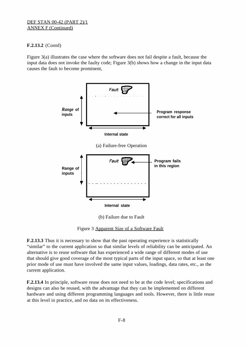
DEF STAN 00-42 (PART 2)/1ANNEX F (Continued)
F.2.13.2 (Contd)
Figure 3(a) illustrates the case where the software does not fail despite a fault, because theinput data does not invoke the faulty code; Figure 3(b) shows how a change in the input datacauses the fault to become prominent,
Range ofinputs
Program responsecorrect for all inputs
Internal state
(a) Failure-free Operation
Program fails
Range ofin this region
inputs
- - -- - - - - - - - - - - - - - -
Internal state
(b) Failure due to Fault
Figure 3 Apparent Size of a Software Fault
F.2.13.3 Thus it is necessary to show that the past operating experience is statistically“similar” to the current application so that similar levels of reliability can be anticipated. Analternative is to reuse software that has experienced a wide range of different modes of usethat should give good coverage of the most typical parts of the input space, so that at least oneprior mode of use must have involved the same input values, loadings, data rates, etc., as thecurrent application.
F.2.13.4 In principle, software reuse does not need to be at the code level; specifications anddesigns can also be reused, with the advantage that they can be implemented on differenthardware and using different programming languages and tools. However, there is little reuseat this level in practice, and no data on its effectiveness.
F-8

DEF STAN 00-42 (PART 2)/1ANNEX F (Continued)
F.2.13.5 Reusable components should be provided with adequate documentation, including aprecise specification. Formal specifications (see E.3.5) will avoid many of the problems oftrying to reuse ambiguously or incompletely defined software.
F.3 Fault Tolerance
F.3.1 Where high reliability is required, it is likely to be necessary to design the system todetect and mitigate software failures. This is best done by appropriate design diversity at thesystem level (eg a programmable and non-programmable system to implement a criticalfunction), but where this is impractical, a degree of fault tolerance can be added to thesoftware itself by means of defensive programming and software diversity.
F.3.2 Defensive Programming
F.3.2.1 Defensive programming is the simplest form of fault tolerance. It works by placingchecks in the software that the program variables are consistent and have not been corrupted.If an inconsistency is detected, some error handling process is initiated.
F.3.2.2 Error detection. Error detection may, for example, be simply by checks included inthe program that the data is within a certain range, or may involve complex relationshipsbetween data items. The code to implement these checks may be generated automatically bythe compiler from assertions included in the source code (these assertions can be derived froma formal specification), but more often the checks have to be coded by hand. Some languages,such as Ada, have exception handling features that transfer control to a handler program if acheck fails. Another mechanism for error detection is to associate error detecting codes(eg checksums) with the data to detect external or internal data corruption.
A serious problem with defensive programming is that the checking code adds to thecomplexity of the software and slows it down, and therefore it should be introduced accordingto a carefully-defined strategy.
F.3.2.3 Error handling. Error handling can be by backward error recovery, forward errorrecovery, fail soft or fail safe strategies. Error recovery is obviously preferable, but it can behard to implement, especially if asynchronous, communicating programs are involved.
(a) Backward error recovery. This is usually implemented by making copies (known ascheckpoints) of the correct state at intervals, and restoring the state from the latest checkpointif an error is detected. It is most useful against transient hardware failures and external faults.
(b) Forward error recovery. This uses redundant information to repair corrupted data. Errordetecting codes are often implemented with extra bits to enable error recovery. Database andfile systems commonly use redundant pointers for error recovery. Diversity can also be used(see below).
F-9

DEF STAN 00-42 (PART 2)/1ANNEX F (Continued)
F.3.2.3 (Contd)
(c) Fail soft. Here the design philosophy is not to mask failures but to reduce theperformance of the system in a defined way. A fail soft philosophy may, for example, beimplemented by reducing the functionality, assuming that some partial operational capabilitycan be identified, or by discarding data (eg alternate inputs).
(d) Fail safe. It maybe possible to handle errors by halting in a safe way. Examples of failsafety are seen in railway signalling, where all signals are set to danger if an error is detectedin the interlocking system, and in nuclear power generation, where the reactor is shut down ifthe safe operating parameters are exceeded. Fail safety is not possible at the system level ifhigh availability is required, but maybe possible at the subsystem level if it can be arrangedfor a faulty component to “fail silent” (ie cease producing output) and a backup subsystem todetect this and take over.
F.3.3 Software Diversity
F.3.3.1 Software diversity is a form of fault tolerance based on the use of two or more diverseprograms to carry out critical functions, on the assumption that the same fault is unlikely tooccur in all the versions. In its most elaborate form, diversity may involve three or fourversions of the software, written by independent teams using different design methods andprogramming languages, and running on different processors.
F.3.3.2 Diversity enables failures of individual versions to be detected, and fault tolerance tobe implemented, by using the output agreed on by the majority to control the system. If all theversions disagree, the system should fail soft or fail safe if possible.
F.3.3.3 Diversity is vulnerable to common mode faults affecting several of the versions,which limit the reliability gain and make it hard to predict. Research has shown that diverseimplementations may suffer from common design errors, possibly because certain parts of thedesign are intrinsically difficult. It may also be difficult to maintain data consistency betweenthe versions, especially if the software maintains an internal state.
F.3.3.4 Software diversity may be difficult to implement for both technical and managerialreasons. Shared activities make it very hard to maintain isolation between the teams, and ithas been found that the costs of diversity increase rapidly with the number of versions. It islikely to be more cost-effective to concentrate resources on fault avoidance and detectionduring development, and diversity, if it is used, should be employed at a system, rather thansoftware, level.
F.3.4 Verification of Fault Tolerance
F.3.4.1 Verification of the effectiveness of fault tolerance is very difficult and involvesdifferent techniques from normal software testing. System-level fault tolerance is normallyverified by simulating failures of components and fault injection on the system or interfaces.
F-10

DEF STAN 00-42 (PART 2)/1ANNEX F (Continued)
F.3.4.1 (Contd)
Software-level fault tolerance (eg defensive programming) is verified by seeding softwarefaults.
F-11

DEF STAN 00-42 (PART 2)/lANNEX F (Concluded)
Collation Page
F-12
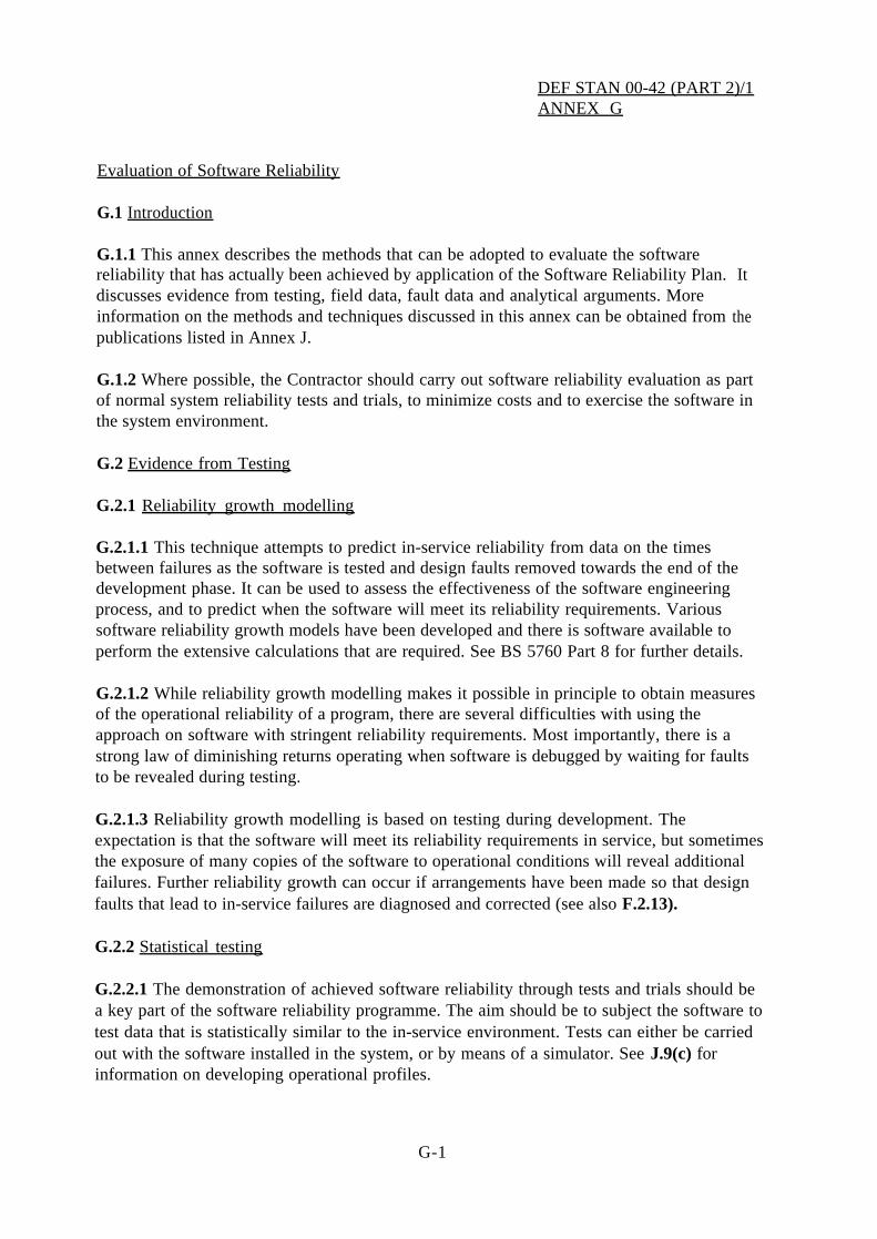
DEF STAN 00-42 (PART 2)/1ANNEX G
Evaluation of Software Reliability
G.1 Introduction
G.1.1 This annex describes the methods that can be adopted to evaluate the softwarereliability that has actually been achieved by application of the Software Reliability Plan.discusses evidence from testing, field data, fault data and analytical arguments. Moreinformation on the methods and techniques discussed in this annex can be obtained frompublications listed in Annex J.
It
the
G.1.2 Where possible, the Contractor should carry out software reliability evaluation as partof normal system reliability tests and trials, to minimize costs and to exercise the software inthe system environment.
G.2 Evidence from Testing
G.2.1 Reliability growth modelling
G.2.1.1 This technique attempts to predict in-service reliability from data on the timesbetween failures as the software is tested and design faults removed towards the end of thedevelopment phase. It can be used to assess the effectiveness of the software engineeringprocess, and to predict when the software will meet its reliability requirements. Varioussoftware reliability growth models have been developed and there is software available toperform the extensive calculations that are required. See BS 5760 Part 8 for further details.
G.2.1.2 While reliability growth modelling makes it possible in principle to obtain measuresof the operational reliability of a program, there are several difficulties with using theapproach on software with stringent reliability requirements. Most importantly, there is astrong law of diminishing returns operating when software is debugged by waiting for faultsto be revealed during testing.
G.2.1.3 Reliability growth modelling is based on testing during development. Theexpectation is that the software will meet its reliability requirements in service, but sometimesthe exposure of many copies of the software to operational conditions will reveal additionalfailures. Further reliability growth can occur if arrangements have been made so that designfaults that lead to in-service failures are diagnosed and corrected (see also F.2.13).
G.2.2 Statistical testing
G.2.2.1 The demonstration of achieved software reliability through tests and trials should bea key part of the software reliability programme. The aim should be to subject the software totest data that is statistically similar to the in-service environment. Tests can either be carriedout with the software installed in the system, or by means of a simulator. See J.9(c) forinformation on developing operational profiles.
G-1

DEF STAN 00-42 (PART 2)/1ANNEX G (Continued)
G.2.2.2 System reliability growth testing, as discussed in Def Stan 00-41, Section Twenty-Six, will provide reliability data under operational conditions.
G.2.2.3 The tests should be carried out over a period several times the required mean time tofailure. It may be difficult to attain this with software with very stringent reliabilityrequirements. Some ways in which testing can be speeded up are:
(a) Testing many copies of the software in parallel with different data sets.
(b) Testing on a faster computer than the eventual target, although this will not uncover errorsin the target processor, or in the compiler unless both test and target processor use the sameobject code.
(c) Using goal-directed (“trajectory”) testing. For a system that is only required to operateoccasionally, such as a shut-down system, the test data can concentrate on values that shouldinitiate action. Because of memory effects, a period of working prior to the demand should beincluded.
G.2.2.4 Because of the large numbers of tests involved, it is desirable to use a diverseimplementation of the software to check the results. This is known as “back-to-back” testing.Prototype versions or a specification animation (see E.4.8) can be used as the diverseimplementation. Alternatively, the tests can be checked against a real-world simulator toestablish that failures do not occur.
G.2.2.5 Very high reliability software may not fail at all during statistical testing. If aparticular version of the software has not failed on test, and if the testing has been carried outfor a time t, it can be shown that there is a 50:50 chance that the software will run for anothertime t without failing. See J.9(a) for details of this result, and J.9(b) for information onstopping rules for testing.
G.2.3 Performance testing
G.2.3.1 Testing maybe carried out to establish that the non-functional performancerequirements have been met. Such tests should include:
(a) tests of specific design features for reliability (eg overload handling and interface errorhandling);
(b) overload/stress tests (see F.2.10.7);
(c) fault tolerance tests, including tests of fault detection, recovery and isolation mechanisms(see F.3.4);
(d) normal and worst case resource utilisation measurements;
G-2
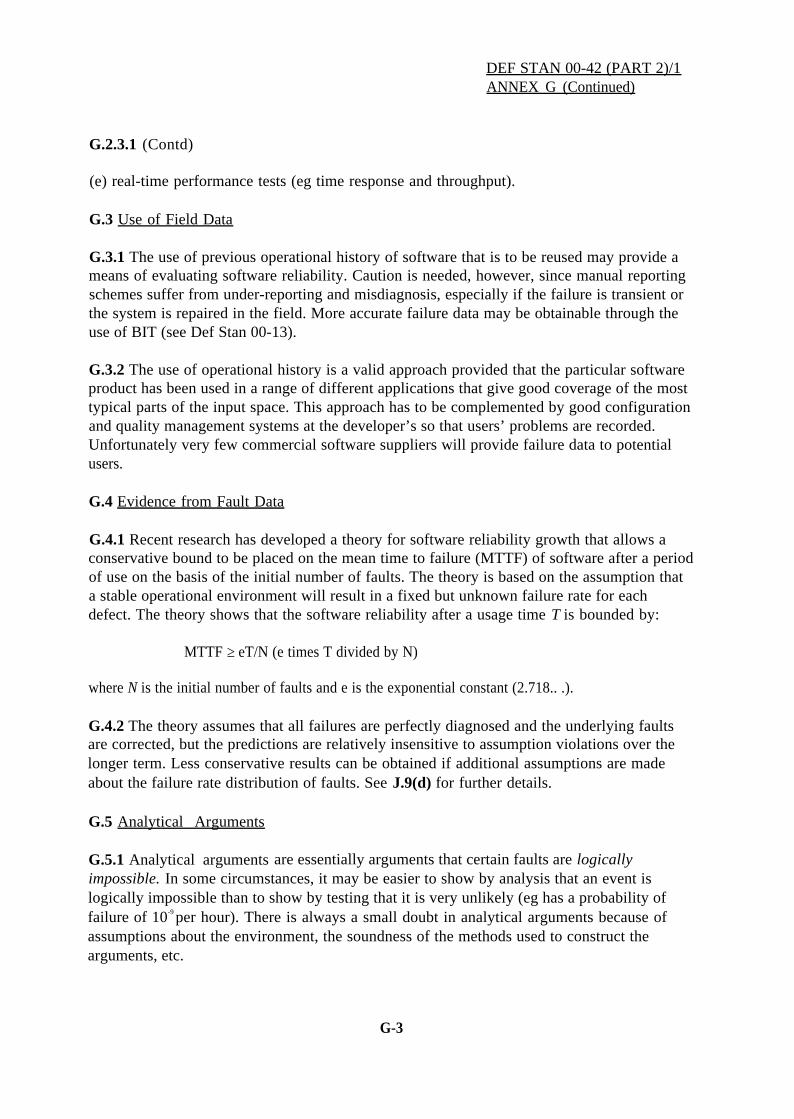
G.2.3.1 (Contd)
DEF STAN 00-42 (PART 2)/1ANNEX G (Continued)
(e) real-time performance tests (eg time response and throughput).
G.3 Use of Field Data
G.3.1 The use of previous operational history of software that is to be reused may provide ameans of evaluating software reliability. Caution is needed, however, since manual reportingschemes suffer from under-reporting and misdiagnosis, especially if the failure is transient orthe system is repaired in the field. More accurate failure data may be obtainable through theuse of BIT (see Def Stan 00-13).
G.3.2 The use of operational history is a valid approach provided that the particular softwareproduct has been used in a range of different applications that give good coverage of the mosttypical parts of the input space. This approach has to be complemented by good configurationand quality management systems at the developer’s so that users’ problems are recorded.Unfortunately very few commercial software suppliers will provide failure data to potentialusers.
G.4 Evidence from Fault Data
G.4.1 Recent research has developed a theory for software reliability growth that allows aconservative bound to be placed on the mean time to failure (MTTF) of software after a periodof use on the basis of the initial number of faults. The theory is based on the assumption thata stable operational environment will result in a fixed but unknown failure rate for eachdefect. The theory shows that the software reliability after a usage time T is bounded by:
MTTF ≥ eT/N (e times T divided by N)
where N is the initial number of faults and e is the exponential constant (2.718.. .).
G.4.2 The theory assumes that all failures are perfectly diagnosed and the underlying faultsare corrected, but the predictions are relatively insensitive to assumption violations over thelonger term. Less conservative results can be obtained if additional assumptions are madeabout the failure rate distribution of faults. See J.9(d) for further details.
G.5 Analytical Arguments
G.5.1 Analytical arguments are essentially arguments that certain faults are logicallyimpossible. In some circumstances, it may be easier to show by analysis that an event islogically impossible than to show by testing that it is very unlikely (eg has a probability offailure of 10-9 per hour). There is always a small doubt in analytical arguments because ofassumptions about the environment, the soundness of the methods used to construct thearguments, etc.
G-3
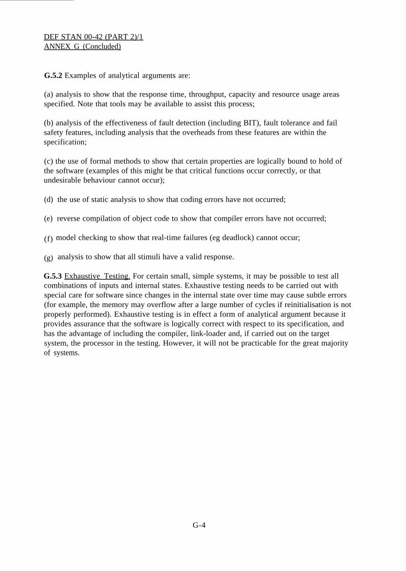
DEF STAN 00-42 (PART 2)/1ANNEX G (Concluded)
G.5.2 Examples of analytical arguments are:
(a) analysis to show that the response time, throughput, capacity and resource usage areasspecified. Note that tools may be available to assist this process;
(b) analysis of the effectiveness of fault detection (including BIT), fault tolerance and failsafety features, including analysis that the overheads from these features are within thespecification;
(c) the use of formal methods to show that certain properties are logically bound to hold ofthe software (examples of this might be that critical functions occur correctly, or thatundesirable behaviour cannot occur);
(d)
(e)
(f)
(g)
the use of static analysis to show that coding errors have not occurred;
reverse compilation of object code to show that compiler errors have not occurred;
model checking to show that real-time failures (eg deadlock) cannot occur;
analysis to show that all stimuli have a valid response.
G.5.3 Exhaustive Testing. For certain small, simple systems, it may be possible to test allcombinations of inputs and internal states. Exhaustive testing needs to be carried out withspecial care for software since changes in the internal state over time may cause subtle errors(for example, the memory may overflow after a large number of cycles if reinitialisation is notproperly performed). Exhaustive testing is in effect a form of analytical argument because itprovides assurance that the software is logically correct with respect to its specification, andhas the advantage of including the compiler, link-loader and, if carried out on the targetsystem, the processor in the testing. However, it will not be practicable for the great majorityof systems.
G-4
DEF STAN 00-42 (PART 2)/1ANNEX H
H.1 ASICs
H.1.1 Introduction
ASICs are being increasingly used in modern electronic systems. These circuits blur theconventional distinction between hardware and software. A functional design in a high levelhardware description language (HDL) is transformed by what is often termed a “siliconcompiler” into a set of photo-lithographic masks for integrated circuit production. State-of-the-art ASICs may contain up to a million gates.
H.1.2 This annex describes the techniques that can be applied for the assurance of reliabilityfor ASICs
H.2 Reliability Achievement for ASICs
H.2.1 Essentially ASICs are another, if rather unusual, form of software with the samepotential for containing design faults, and should be subjected to similar forms of evaluation.Assurance is required that the design is logically correct with respect to its specification.
H.2.2 Commercial tools to enable model checking and verification of HDL designs areavailable. For high reliability requirements, formal methods should be used (see E.3.5). Inaddition, design simulation should be used to check the validity of the design. Exhaustivesimulation can be achieved even for large input spaces by partitioning the circuit into a seriesof sub-modules. This requires partitioning to be an essential part of the functional design andis an overhead appropriate to critical applications.
ASICs are also hardware, so assurance is additionally required of the integrity of thetranslation of the design into silicon. This will involve assurance that the following aresatisfactory:
(a) the fabrication technology, which changes rapidly;
(b) the acceptance test procedures for the fabricated chip samples, which will change as thefabrication technology changes;
(c) the tests to be applied when reproducing the design on a production basis;
(d) the built-in tests to detect production and operational faults.
H.2.4 BIT for ASICs utilizes test vector generation and fault detection by an added part of thecircuitry. This concept can be used for production tests and for automatic on-line diagnosticsto detect operational faults, which may greatly extend maintenance test intervals. The factthat the design is “frozen” in silicon also has potential benefits in simplifying version andconfiguration control and could be seen as the best form for a certified device or system.
H-1

DEF STAN 00-42 (PART 2)/1ANNEX H (Concluded)
Collation Page
H-2

DEF STAN 00-42 (PART 2)/1ANNEX J
Bibliography
J.1 The following publications provide further technical information on the methods andtechniques discussed in this Standard.
J.2 Standards and Guidelines
(a)
(b)
(c)
(d)
(e)
(f)
IEC 1508, Functional Safety: Safety-related Systems (parts 1 to 7), draft edition 1,June 1995
RCTA/DO 178B, Software Considerations in Airborne Systems and Equipment
Def Stan 00-43, Reliability and Maintainability Assurance Activity
IEEE Std 982.2-1988, IEEE Guide for the Use of IEEE Standard Dictionary ofMeasures to Produce Reliable Software
J-STD-016-1995, Standard for Information Technology Software Life Cycle ProcessesSoftware Development Acquirer-Supplier Agreement
Guidelines for the documentation of computer software for real time and interactivesystems, The Institution of Electrical Engineers
J.3 General
(a)
(b)
(c)
(d)
(e)
(f)
Dependability of Critical Computer Systems 1, ed. F J Redmill, Elsevier AppliedScience, 1988. ISBN 1-85166-203-0
I Somerville, Software Engineering. Addison-Wesley, 5th edition, 1996. ISBN 0-201-56529-3
R S Pressman, Software Engineering: a Practitioner’s Approach, 3rd edition,McGraw Hill, New York, 1992
Software Reliability Handbook, ed. Paul Rook, Elsevier Applied Science, 1990.ISBN1-85166-400-9
Michael R Lyu, Handbook of Software Reliability Engineering, McGraw-Hill, 1996.ISBN 0-07-039400-8
J A McDermid, Software Engineer’s Reference Book, Butterworth Heinemann, 1991.ISBN 0750608137
J-1

DEF STAN 00-42 (PART 2)/1ANNEX J (Continued)
J.4 Inspections
(a) T Gilb and D Graham, Software Inspections, Addison-Wesley, 1994
J.5 Measures and Metrics
(a) N E Fenton and S L Pleeger, Software Metrics: A Rigorous and Practical Approach,2nd edition, International Thomson Computer Press, 1996
J.6 Formal Methods
(a) FME’96: Industrial Benefit and Advances in Formal Methods, ed. Marie-ClaudeGaudel and James Woodcock, Springer LNCS 1051, 1996. ISBN 3-540-60973-3.
J.7 Reliability Analysis
(a) N G Leveson and P R Harvey, Analysing software safety, IEEE Trans. SoftwareEngineering, 9(5), pp569-79, 1983
(b) E Noe-Gonzales, “The Software Error Effect Analysis”, in V Maggioli (ed.), Proc.Safecomp ’94, Instrument Society of America, 1994. ISBN 1-55617-536-1
(c) N G Leveson, Safeware, Addison Wesley, 1995, ISBN 0-201-11972-2
(d) J A McDermid, “Software Hazard and Safety Analysis: Opportunities and Challenges”in Safety Critical Systems: The Convergence of High Tech and Human Factors, editedby Felix Redmill and Tom Anderson, published by Springer Verlang, 1996, ISBN 3-540-76009-1
J.8 Software Engineering Process
(a) M Paulk, B Curtis, M Chrissis, C Weber, Capability Maturity Model for Software(Version 1.1), Carnegie Mellon University, CMU/SEI-93-TR-24
J.9 Reliability Evaluation
(a) B Littlewood and L Strigini, Validation of ultra-high dependability for software-basedsystems, Communications of the ACM, Vol. 36, No. 11, pp69–80, November 1993
(b) B Littlewood, D Wright, “Stopping rules for the operational testing of safety-criticalsoftware”, Digest of IEEE 1995 FTC’S, 25th Annual International Symposium Fault-Tolerant Computing, (Pasadena), IEEE Computer Society Silver Spring, Md., pp444-451, 1995
J-2

DEF STAN 00-42 (PART 2)/1ANNEX J (Continued)
J.9 (Contd)
(c) John D Muss, Operational Profiles in Software-Reliability Engineering, IEEE, 1992
(d) P G Bishop and R E Bloomfield, “A Conservative Theory for Long-Term ReliabilityGrowth Prediction,” in Proc. Seventh International Symposium on Software ReliabilityEngineering (ISSRE’96), White Plains, New York, 1996
J.10 Coding Standards
(a) Les Hatton, Safer C: Developing Software for High Integrity and Safety CriticalSystems, McGraw Hill, 1995. ISBN 0-07-707640-0
J-3

DEF STAN 00-42 (PART 2)/1ANNEX J (Concluded)
Collation Page
J-4

Collation Page

DEF STAN 00-42(PART 2)/1
© Crown Copyright 1997 This Standard may be fully reproducedexcept for sale purposes. The
Published by and obtainable from: following conditions must be observed:Ministry of Defence 1 The Royal Coat of Arms and theDirectorate of Standardization publishing imprint are to beStan Ops 1, Room 1138 omitted.Kentigern House 2 The following statement is to be65 Brown Street inserted on the cover:GLASGOW G2 8EX “Crown Copyright. Reprinted by
(name of organization) with theTel No: 0141-224 2531/2 permission of Her Majesty’sFax No: 0141-224 2503 Stationery Office.”
Requests for commercial reproductionshould be addressed to:Ministry of DefenceStan Ops 1, Room 1138Kentigern House65 Brown Street,GLASGOW G2 8EX
The following Defence Standard file reference relates to the work on thisStandard - D/D Stan/350/03/17
Contract Requirements
When Defence Standards are incorporated into contracts users are responsiblefor their correct application and for complying with contract requirements.
Revision of Defence Standards
Defence Standards are revised when necessary by the issue either ofamendments or of revised editions. It is important that users of DefenceStandards should ascertain that they are in possession of the latestamendments or editions. Information on all Defence Standards is contained inDef Stan 00-00 (Part 3) Section 4, Index of Standards for DefenceProcurement - Index of Defence Standards and Specifications publishedannually and supplemented periodically by Standards in Defence News. Anyperson who, when making use of a Defence Standard encounters an inaccuracyor ambiguity is requested to notify the Directorate of Standardization withoutdelay in order that the matter may be investigated and appropriate actiontaken.