is 6533-1 (1989): code of practice for design and
TRANSCRIPT

Disclosure to Promote the Right To Information
Whereas the Parliament of India has set out to provide a practical regime of right to information for citizens to secure access to information under the control of public authorities, in order to promote transparency and accountability in the working of every public authority, and whereas the attached publication of the Bureau of Indian Standards is of particular interest to the public, particularly disadvantaged communities and those engaged in the pursuit of education and knowledge, the attached public safety standard is made available to promote the timely dissemination of this information in an accurate manner to the public.
इंटरनेट मानक
“!ान $ एक न' भारत का +नम-ण”Satyanarayan Gangaram Pitroda
“Invent a New India Using Knowledge”
“प0रा1 को छोड न' 5 तरफ”Jawaharlal Nehru
“Step Out From the Old to the New”
“जान1 का अ+धकार, जी1 का अ+धकार”Mazdoor Kisan Shakti Sangathan
“The Right to Information, The Right to Live”
“!ान एक ऐसा खजाना > जो कभी च0राया नहB जा सकता है”Bhartṛhari—Nītiśatakam
“Knowledge is such a treasure which cannot be stolen”
“Invent a New India Using Knowledge”
है”ह”ह
IS 6533-1 (1989): Code of practice for design andconstruction of steel chimneys, Part 1: Mechanical aspects[CED 7: Structural Engineering and structural sections]


":-"~.: IS 6533 ( Part 1) : 1989 (Reaffirmed 1995)
REAFFIRMED 2010
Indian Standard
DESIGN AND CONSTRUCTION OF STEELCHIMNEY— CODE OF PRACTICE
PART 1 MECHANICAL ASPECT
( First Revision)
Fourth Reprint SEPTEMBER 2003
UDC 697.8 [ 669.14 ] : 006.76
© BIS 1990
BUREAU OF INDIAN STANDARDSMANAK BRAVAN, 9 BAHADUR SHAH ZAFAR MARG
NEW DELHI 110002
September 1990 Price Group 8

A~It,"LJ~Il:-" I ~'). I ,)\ I ')l~I·.lt I~91'1'0
IS 6533 (PART 1) : 1'8' DESIGN AND CONSTRUCTIONorSTEIL CHIMNEY - CODE OF PRAC'I'ICE
PART 1 MECHANICAL ASPECT
( First R."u;oll)
(,.,. 15, c..·11-1.1 ) - Subsritute the following Cor the existing
tom.II: -l'8 • [~~~)
Modify abc cldillilioa liveD for parameter D under tbeabove Connula IS:
D. dillDClaof.taek at the exit of tile Chlmocy in m.
{CEO')Reproaraplay Uait,81S.NewDelhi,lndia

Structural Engineering Sectional Committee, 5MBDC 7
FOREWORD
Thi~ Indian Standard ( Part 1 ) ( First Revision) was adopted by the Bureau of Indian Standardson 20 April 1989, after the draft finalized by the Structural Engineering Sectional Committeehad been approved by the Structural and Metals Division Council.
This standard was first published in 1971. On suggestions by practising engineers andrepresentatives of various organizations in the country, the Sectional Committee decided tobifurcate the standard in t\VO parts, separating structural aspects from the mechanical aspectsa, follows:
Part 1 Mechanical aspects, and
Part 2 Structural aspects.
The present practice of design of steel chimney recognizes the influence of aerodynamic shadowon the height of chimney and this aspect has been taken into account in this revision in additionto the consideration of regulations on atmospheric pollution.
Design and construction of chimneys has become specialized field with scope for the furtherresearch and modifications. Therefore, attempt has been made in this standard (Part 1) tocover only the basic requirements. The designer should use his discretion in the use of researchdata available.
Appendix G of the earlier version of the standard had dealt with the calculation of dispersionin atmosphere of emission of uust and sulphur dioxide from power and steam generating chimneysonly. In this standard ( Part 1 ) a more generalized approach for the determination" of height ofchimneys in relation to concentration of pollutants has been included keeping in view anacceptable air quality standard at the ground level.
In the preparation of this standard, considerable assistance has been derived from BS 4076 : 1978'Specification for steel chimneys', covered by the British Standards Institution, UK.

Indian Standard
DESIGN AND CONSTRUCTION OF STEELCHIMNEY - CODE OF PRACTICE
PART t MECHANICAL ASPECT
( First Revision)
1 SCOPE 4 TERMINOLOGY
4.2 Blaakiag Off Plate
An imperforate plate fitted immediatelybeneath the inlet of a chimney to prevent thewaste gases reaching the lower portion of thechimney.
4.3 Boller EfticieDcy
The ratio of heat used in the boiler to theavailable heat.
4.4 Boiler-Mounted ChilDDey
A chimney supported by a boiler and itsfoundation.
4.5 Drart Loss
Drop in static pressure of gas between twopoints in a system.
4.6 Efflux Velocity
The speed of discharge of gases from the topof the chimney.
4.7 Flux GISTemperature
Temperature of flue gas at the chimney outlet.
4.8 Forced Dr.ft
IS 8: 1983
2.1 The following Indian Standardsnecessary adjuncts to this standard:
IS No. Title
IS 6 : 1983 Specification for the moderate heat duty fireclay refractories, group 'A' (fourthrevision)
Specification for high heatduty fireclay refractories,group 'B' (fourth revision)
IS 460 Specification for test sieves:( Part 1 ): 985 Part 1 Wire cloth test sieves
( thirdrevision )
IS 460 Specification for test sieves:( Part 2) : 1985 Part 2 Perforated plate test
sieves( thirdrevision)
IS 2042 : 1972 Specification for insulatingbricks (first revision)
lS 4041 : 1987 Glossary of terms relatingto refractory materials (firstrevision )
IS 8829 : 1978 Guidelines for micrometeorological techniques in airpollution studies
1.1 This standard (Part 1) covers design, 4.0 For the purpose of this standard termlnoconstruction, maintenance and inspection of 10BY as defined in 4.1 to 4.21 shall apply. Formechanical aspects of steel chimneys. The definitions not covered in this part, a referencemechanical aspects include lining, draft calcula- shall be made to Part 2 of the standard.tions, considerations of dispersion of pollutantsand ash disposal. 4.1 ActualDraft
2 REFERENCES The suction produced at the base of a chimneyminus the drop in draft due to frictional resist-
are anee in ftue gas passages.
3 STATUTORY PROVISIONS System which maintains the products of3.1 Compliance with this code does not relieve combustion, when flown to or through it, at aanyone from the responsibility of observing pressure above atmospheric.provisions as may have been promulgated by 4.9 Ground Leyel CODceDtratloDany statutory bodies and/or observing provincialbuilding by-laws and the civil aviation require- Concentration of air pollutant in ma/ml in themeats pertaining to such structures. breathing zone.
I

a) Steel chimneys are ideally suited forprocess work where a short heat upperiod and low thermal capacity arerequired whereas it encourages acidcondensation and corrosion hence smutting and reduction in the life of chimney;
b) Guyed steel chimneys are better suitedwhere the supporting capability of thesoil is low whereas it involves regularmaintenance of guy wires anchor pointsand other fittings in addition to difficultyin finding suitable anchor points of guysat ground;
c) Reinforced cement concrete chimneysare more expensive than other forms ofconstruction up to about 4S m heightbut above this, they are very competitive.Above 65 m height, they are more readilyacceptable because of their flexibility ofshape and flue layouts, in addition tothe absence of any limitation on size; and
d) Brick chimneys are suitable in clayindustries for use with intermittent kilnfiring and with very high exhaust gastemperatures. They are cheaper forsmaller heights but require regular at tention and, therefore, involve highermaintenance cost.
SECTION 1 DESIGN
5 GENEllAL CONSIDERATIONS
5.1 Claal8eatioD of ClallDDeys
On the basis of types of construction of theshaft, the chimneysare classified into two types,Dame]y, self.supportins and guyed. The chimneymay be lined either over the entire or partheiaht depending upon the temperature and/oragressiveness of the flue gases. The inlet forthe flue gases may be below or above theground level.
5.2 SelectioD of Chi.Dey
5.2.1 In the selection of chimneys, advantagesand disadvantages of steel chimneys versuschimneys with other construction material, suchas reinforced cement concrete/masonry shouldbe considered with reference to overalleconomy. Some of the important advantagesand disadvantages of chimneys of differentmaterials of construction are as follows:
4.21 Tun Don Ratio of Boller
Ratio of fuel firing at maximum and minimumloads.
'-.20 Theoretical Draft
The suction that would be produced at thebaseof a chimney with no ftue losses. 5.%.% Some of the important factors to be
considered in choosing the chimney are asfollows:
a) Characteristics of the equipment forwhich the chimney is designed, including
II 833(r. 1): 1Mt
4.10 Helilit of 01..,It i. the di.tance between the centre lineofthe incomiD-' lue Itreem to tbe top or thechimney. Howeyer the heilht of chimneyfor atmospheric dispersion modelliol sball betaken al the distance between the afound leveland the chimney'. top.
4.11 Horlzolltal To, Plate
A horizontal calt iron plate fitted to the topor the structural shell coveriDI tbe areabetween it and the liners.
4.12 Ia." Draft
System which maintains the products of combustion, when flown to or throUlh it, at a proaressively increasiDI sub.atmospheric pressure.
4.13 M.. Rate of EalllioD
Emission of pollutants from a chimney in termsof mass per unit of time.
4.14 Nataral Dnft
Draft created in the boiler unit due to chimneyonly.
4.15 Nomi.al CbilDDey Diameter
Internal diameter at the topmost opening ofthe steel shell.
4.16 Oatpat EIlcieDcy
Ratio of energy equivalent of draft per kg ofpses produced by artificial draft to the energyequivalent per kg of pses or the additionalheat carried away by the flue ps due to naturaldraft.
4.17 PI•••
The trajectory of the movement of pses discharged from a chimney.
4.18 Refractory Work
All terms relatingto refractory work shall bein accordance with IS 4041 : 1987.
4.19 Siopial CapPlate
A sloping cast iron plate fitted to the top ofthe structural shells covering the area betweenit and the liners and incorporating cravatsthrough which the linersprotrude.
2

IS '533 ( Part 1 ) :1.
a) Draft required by the plant;b) Efficiency of the source generating flue
gases;c) Fuel adopted ( provisions in boiler desian
to fire any inferior Brade rue1 in futureshall also be considered );
d) Excel. air~requirement;e) Sito data (ambient air temperature,
barometric pressure );f) Flue ps temperature;8) Flue sas velocity;h) Proposed type of construction of the
chimney;j) Natural or mechanical draft;k) Lenph of horizontal flue run; andm) Tum-down ratio.
5.3.2 The basic dimensions of steel cbimneyfrom consideration of strensth and stabilityshall satisfy the relevant provisions of Part 2of this standard.
information:
!.3.1 The basic dimensions of the chimney,namely, the height and clear diameter or crosssectional area of individual flues or in multi- 5.3.3 As a guideline, the nominal dimensionsflues stacks depend upon the following of steel chimney are given in Table 1.
Dumber of units, type, etc. taking intoaccount future expansion of units if theproposed chimney is to cater for theseunits also;
b) Typeor fuel used;c) In the case of boilers, surface area, out
put efficiency, draft required, etc;d) Mode of operation;e) Temperature of the flue gas before enter
ing the chimney and its likely variation;f) Composition of the flue gas, its specific
weight, quantity of dust data about theaggressiveaess of the gases. These factorsdecide the type of lining;
g) Local statutory regulations relating toheight, dispersion of pollutants, provisionfor earthing, aviation warniDI lamp,health, etc, and
h) The mode of erection of chimney.
S.3 Bulc 01...108.
Table 1 Reeo._._ Heillat to DllIDeter aatlo of Steel ChbBey
Nominal DI_eter of Cbl._, HelPt of SteelSlla'tem m
,.-________A ____~
~-----
-A-____ .,Unlined Lined 15 20 25 30 35 40 45 50 55 60 70 80 90 100 110
'0 x60 x80 SO x
100 60 x120 80 x )(
140 100 x X
160 120 X )( x x180 140 x x x )( x200 160 x x )( x220 180 )( x240 200 X x280 240 x X
315 275 x )(
355 315 X )(
400 360 )( )(
450 410 )(
~OTE - ')( , denotes more commonly used dimensions.
3

IS 633 ( PUll) : UB
5.3.4 The clear diameter of the chimney is thenominal diameter of the shell if the chimneyis unlined or partially Uned. For fully linedchimney, the clear diameter of the chimneywill be the clear diameter of the lining at theto,. The Cully lined chimney. shall have amInimum clear diameter of SOO mm. If, fortechnological reaSODS, it is necessary to havea amaller diameter, the top openiol shall bereducedby CODstructina the passale locally.
5.3.5 The chimney shall be at leut 5 m tallerthan the tallest buildiDIin a surrounding areaof 1SO m radius unlel. other replatioDS do Dotnecessitate a taller chimney (I" also 7 ).
6. CALCULATIONS
'.1 The draft IOIIeI in combustion chamber.HI vary dependiDI on the actual deliln andthis may beworked out based on aerodynamiccalculations. Hence. the draft IOSleI at theexit Bailie of the combustion chamber or theboiler should be provided by the customer. forit will not be pouible to standardize d.aftJOIIe. for varioul types of combustionchamben, boiler capacities, etc. The total losswiD be the sum. of the losses at the exit ftanaeof the boiler and the losses in p-ecipitatorl andthe coDnectiDI duet., in case of coal fired boilers and the lossat the exit lanle of the boilersplus the losses in the connection ducts in caseof oil and pa fired boilers. These losses plus the1011 in the cbimnex shall be considered alODawith the draft available OD accountof forced orinduced draft systems while mDI up the height.The losses across the precipitators will alsohave to be liven by the customer.
'-2 Jasl. DI..eterof tile CldJuey
The inside diameter of the chimney in m iscalculated a. follows:
D-£ /4U""'V KY.
whereQ ==r quantity of the aas in ml/sec, and
J'01 ::.: velocity of the flue gas at exitpoint of chimney in m/sec.
e However, the diameter shall be so chosen thatthe velocity will not exceed, under anycircumstances, 30 m/sec.The optimum faDle of velocity may be takenas IS to 20m/sec.,.3 Dnft~The followiDa draft losses shall be considered:
a) Draft losses through the chimney d. in!DID of water column may be calculatedas:
4/HY'tI. - 2,D ."
b) Draft losIes through the ducts dd in mmof water column may be calculated as:
4j1VI.dd - 2gD I • pi
c) Draft'losses in bends db in mm of watercolumn may be calculated al:
KIV'd,,- 2g . F,d) Draft loues due to sudden chanle of
sections de in mm of water will dependupon the dearee of sharpness, form ofsection and the ratio of area of thesection after and before the chanse.Also, if the chanle in section is padual,that is, if enJaraement or contraction is~dualt the loss will depend on theIDcluded anale. It may be calculated.s follows:
K~·1) J. --;1. P, when the chanle
of sectio~ is abrupt, and
K,K.V.'2) d• ....~. P, when the chanle
of section is Iradual.e) Draft loss due to kinetic enerlY at the
exit:y.
dll. - 2, · p,'.3.1 Lelends used in the above formulaeare explained as under:
4.,4.,4." d.and
dk - draft losses as explained above, in filmof water column;
/ == fanning friction factor;H - height of the chimney in m;I - Length of the duct in m;
D - diameter of the chimney in m;- shaft diameter in case of cylindrical
chimney and average diameter in caseof conical chimney of smaller height:
D1 == diameter of the duct in m, if circularin cross-section; or
2AB ef tieA+B 1 rec ansu ar In cross sect on
with A and B as dimensions;V - velocity of gas in m/sec;Vt - velocity of las in the ftue duct in
m/sec;V. - velocity of. sas in m/sec after the
change in section;XI .a coefficient of friction as obtained
from File 1;
4

o
,A leI - 1'ea 18 1(1 - 0'75
f.O
1H K1 - "8
~- OJ'I10 Kl - 0"5 1£ Kl - 1"65 X rId fF K. - , •• )( tid
~0
t I~-
I , 0---- ~
1G K) 0"72 X ,/0 '" K. - 1'5 1K KI - 1-5
{fJ-
t
FIG. 1 COEPFICIENT 0' FRICTION ( K1 ) IN BENDS

IS 'S33( Part I): I.
: 20 percent, Max
: I 300°C, Min
: 1 mm, !tIQX: ± 1-5 percent
: Not less than 14N/mm'
: Up to 3-3 x lO-er'K
: 2-0 percent,Alax: 15 cycles, Min
: About 1·25 WI(mK)
: Not less than 2 000kg/rna
: 30percent, Alin
con-
c) Cold crushingstrength
d) Coefficient of expansion
e) Aluminium oxide. • ( AI!O. )
f) Acid solubilityg) Spalling resis-
tance
b) Approximateporosity
j) Refractorinessunder load(R.U.L)
k) Warpage
m) Size tolerance
Suitable bricks shall have the followingproperties:
a) Thermalductivity
b) Bulk density
These are made in radial form to suit thechimney dimensions. Firebricks having analumina content between 28 and 32 percent aresatisfactory for the majority of applications.These bricks are set in mortar made fromground fireclay or in a suitable fire cement.
This type of linial fulfils requirement 8.1(b)and to a certain extent requirements 8.1(a)up to a temperature of about 1 2000C butits high density makes it of little use in respectof requirement 8.1(c). Its strength and hardsurface would give protection to the steel fromabrasion when this has to be considered.
a) To protect the chimney shell from heat,
b) To act as a protective coveriDI thusreduciDI corrosion, and
c) To maintain the temperature of the fluepses.
I.Z Materials
1.2.1 ~"b,ick,
K. - coefficient of friction due to suddenchanle in section as obtained fromFi,. 2;
K. - factor for Iradual chanle in sectionas obtained from FiS. 3;
I - acceleration due to gravity in m/sl ;and
FI - averagedensity of fuel ps within thechimney, in ducts, in bends or at theexit; as appropriate in kg/mi.
'.4 The draft induced by the chimney, d. inmm of water column is:
d.-H(pa-pg)
whereptJ - density of air at ambient tempera
ture and pressure in kllml , andPg = density of gas at average tempera
ture and pressure within chimneyin kg/ml .
6.5 The draft available in the chimney ascalculated in 6.4 should take care of all thedraft losses as calculated in 6.3 (adjustedfor the usage of forced draft and induced draftfans). The height and diameter of the chimneyshould be so chosen as to obtain the necessarydraft and the necessary exit velocity.
7 DETERMINATION OF HEIGHT OFCHIMNEY7.1 The height of chimney chosen shall satisfythe requirement given in 6.5.
7.1 The influence of aerodynamic shadow onthe height of the chimney shall be assessed inaccordance with Annex A.
7.3 While deciding the actual height of thechimney, consideration of dispersion of pollutants on the height of chimney as covered inIS 8829 : 1978 shall be taken. In the absenceof availability of sufficient data regardingmeteorological techniques in air pollutionstudy, methodas given in Annex B shallbe takeninto account. This Annex also covers recommended height of stacks for process gases frompollution consideration for iron and steelindustries in particular.
7.4 The final adoptable height of the chimneyshall be based on all the factors covered in 7.1and 7.3.
8.2.1.1 Mortar for fireclay bricks ( hard fired ),mixed with blast furnace slag cement in theratio 80 : 20, should have the followingproperties:
SECTION 2 LINING AND INSULATION
8 CHIMNEY LINING
8.1 General
Lining for steel chimney may be required forone or more of the following purposes:
a) Aluminium oxide( AIIO,)
20 percent, Min
6

.,
......_--.
~
I!/r
II
II
I
II
I1/
JV
IV
)Vo
10 20 30 40-C( IN O£GREES~
FIG. 3 COEFFICIENT OF FRICTION ( K.) DUETO GRADUAL CHANGS IN SECTION
0-2
0·1
CONTRACTION
~-2--- AJ~
Oel
o (»-2 0·' o-e 0.. '·0-.!l ...
A2
FIG. 2 COEFnclENT 0' FRICTION ( K.) DUETO SUDDEN CHANGE IN SECTION
K2 0.6
g) Workability Good
8.1.1.2. Blast furnace slag cement should have
b) Ferric oxide( FetOI )
c) Pyrometric coneequivalent, Standard cone No.(ASTM)
d) Dry shrinkage
r) Fired shrinkage
f) Grading
2·5 percent, Max
28, Min
2'5 percent, Maxat 110°C
2'5 percent, Maxat 1 2S0°C/2 hroto 1 mm
-95 percent, Minpassing 1 mmsieve
-so percent, Minpassing 0'09rom sieve
the following chemical composition:
a) Sio, 25 to 26 percent
b) AIIO. 12 to 14 percent
c) FeJO. 2·0 percent, Max
d) Cao 48 to 50 percent
8.%.1.3 In case the chimney bas to dischargegases from processes or incinerators at a temperature higher than 1 200°C, special duty liningbas to be used as given in IS 6 : 1983 and IS 8 :1983.
8.1.1 Insulation Refractory Bricks
These bricks are used for achieving all thethree functions of the insulation. These bricksare available in three grades suitable to temperatures 850, 1 250and 1 500°C. These bricks shallconform to IS 2042 : 1 972. The application issimilar to that of firebricks. Insulating bricksshall .. however, fulfil the followingproperties.
a) AI.O,b) Porosity, percentc) Cold crushing strength, N/mmrd) Bulk density, kg/ml •
e) Thermal conductivity, w/(mk)
f) Size tolerance
Service Temperature,-------------"""----------.---~
· , 1 200°C . 1 OSO°C\
30 to 33 percent t" ,
60,~in 72,Afin3'S, Min 0·8, Min ",- ..
1 000, Max 630 to 7350-31 at hot face temp 0'2 at ~60~Cmel.il ~~.{.- ·
of 600°C . ~
± 2%or ± 2 mm ± 2% or ± 2 mm
1

18 '533 ( pan 1):~
Lilht weipt mlulatina bricks shall have the 1500C (that is in the neipbourhood of dewfollowing propenies: point ). They are set in aD acid resistiulcement
SerJlc, r"""",,,.,r- .,__..-..__A -- -..~
1200ec AI", 1 0500C Mi"28 perceDt, MI"2·S percent, Mta29, MI"
a) Al.o.b) Pe.O.c) Pyrometric CODe equivalent
Standard cone ( ASTM ) No.d) Dry shrinDle ( %)e) Fired sbrinDle ( %)
f) OradiDI, mm
I) Workability
3, Max at l100Cl2000C
3·5, Max at 2hoto 1 (95% palsiD8
O·S mm sieve )Good
3, Max (dry and fired)
oto 1 ( 95% passinsO·S mm sieve)
Good
Not Ifeator thaD0-23 W/(mk);Not leu tbaD 100kl/ml ,
Not lesl thaa 4-6N/mml ,
2-0±O·1 x IQ-l/K.and
0-90 N/mml
8 Max
25M;n
Type 2
2 M'"
96 Min
± 2 or :I: 2 mm
and, as the object is to ,resent an imperviouslinin" severe ftuetuatl0DS of temperatureshould be avoided, otherwise the rilidity orthe lining may cause it to fracture and becomeless efficient. It follows that this class ofbrick is suitable for requirement in 1.1 (b) incircumstances for low ftue las temperature.
It is practicable to use hiJhly vitrified claybricks or vitriled firebrIcks. resistant totemperature up to S40·C and 1 100°C,respectively.
The acid relistiDI bricks and cement should bechosen specifically to resist the acids known orexpected to be prelent in the ftue gases.
Suitable bricks shall have the followingproperties:
a) SpalliDI resi••taace ( cycle)
b) Cold cruahilll 50Minstrenath,N/mm'
c) Water absorp- 2 to 4tioD, percent
d) Acid reli.. 99 MilltaDce
e) Bulk deDlity, 2 200 Min 2400 to 2 SOOklIma
f) Size toler.. :l: 2rance, percent
1.2.4.1 Mortar for acid proof bricks shouldhave tbe followiDI propenies:
a) -AltO. 10percentb) FiDaell All paSSiDI throulh
1 mm sieve eon(ormiDI to IS 460( 'art I orPart 2) :1985
Suitable brieks shall have the followiDIpropertios:
a) Thermal conducti·vity
b) Bulk deality
c) Cold crUlhiDIItrenJth
d) CoellcieDt orliDear ezpulioa
e) Modulus ofrapture
1.2.4 ~c'tllWll"", BrIe'"
nele bricb an uecI whe. the he lUI' arehiply acidic or areat teIDperature It or below
L2.3 Solid Gr. Dlltomtlc,oUl ( Mol. ) Brlckl
The bricks are made to suit the diameter ofchimney and in suitable thickness (Ienerally,between 76 to 114 mm) to suit the degree ofiIlIulatioD required. This type of brick is setin mortar made from the brickmaterial groundto powder form with the addition of Portlandor hilh alumina cement, accordiDI to the brickmanUfacturers.
Thil clasl of lininl would cover requirementsin 1.1 <a> and (c) and dependiDI upon the typeof ps, requIrement in 1.1 (b) within thetemperature raDle 150 to aooGe.When dry, this material hal lowcoefficient ofexpansion and is resistant to temperaturechanles. leiDI hiahly water.absorbaDt, thesebricks should be atored in dry surroundiDls;brick linin" should be dried out slow)y andpreferably, maintained at an elevated temperature thereafter.
I

,
c) Firina shrillk- 2 percent MtIX, atale I ..C
d) Acid solubility 1-5 MfIX
8.2.5 SDlldOr., Dltltontl.JceoUl Co"cr,t,
The agrepte Cor solid arade diatomaceousconcrete is or the same materials as the bricksmentioned above, in appropriate Iradinss, andis mixed with high alumina cement. Theconcretecan beprecast in shapes as required,cast ill Ii'" or placed by the 'luDDinl' procesl.The thickness of the monolithic lillin_ sball,in no case, be less than SO mm. A minimumcover of 25 mm shall beprovided to anchoraleswherecorrosive conditions exist.
This class of linin. has a relative.ly low cacftlcient of expansion and would Cover requirements or Ll <a> and (c) and, de~DdiDI uponthe type of ps, requirement of8.1 (b) in thetemperature raDle 150 to 870·C_
8.2.' R'fractory Coner,t,
A refractory concrete lininl may be formedin situ or applied by the 'sunniag' process. Inuse, it is similar to a firebrick linin, and fulfilssimilar requirements.8.1.7 SandlindC,ment Mixtures
These are suitable for lininas constructed bythe luaninl process, moreImerally for use inthe low temperature range,
8.2.8 Other Materials
Other Iinins materials may be required for usein special circumstances and these shall beapplied in accordancewith the manufacturer'.specification.
a.3 Deslp aM C••netlo.
8.3.1 G,,,,I'QI
The interior surface or the steel sbell shall beclean and sbatl be free from loose rust andscale. for example by wire brushiDI, immediately before applying the liniol.
1.3.2 TIJIrmtll Expan,ion
The thermal expansioD of the liniD, shall beprovided for, in the delilD. Refractory andacid resistant lininls shill be divided intosections; a suitable heiaht of section is 6 ID.Each section of the lining shall be supported byan internal steel rina securely attached to thechimney shell. A space for expansion sballbeJeft above the top of each section so that itremains clear of the rins above. The expansionspace shall be filled.with refractory fi~re.mineral wool or other phable, non-combustiblefilling_
118U(IWtI)11B
The thermal ex~llIiOD of IOlid pad, diatomaceous earth bricksor of CODcrete made fromsimilar material. "eiD,low, IeCtioD heip'a ...)'be Ireater, and for lmall chimneys, a 110iol ofthese materials IBly be tatea almOit to the topor the shell without dividilll it iDto aectioal.Due consideration Ihould be live. to the rebeat shrinDle of theae materiall.
The upper ponion of sucha liaiDI i. lubject todamal' by weather and it should, theretor.,terminateat a distance below the top approximately equal to the diameter of the Ibell, thelining beiDI completed with All enpneerialbrick or dense firebrick, joiated with. suitablemortar. It is recolDlDended that the top aartaceof the IiDialShould be suitably protectedfromthe 'weather_
8.3.3 BrlckwD'1c
Shaped bricks shall be used for chimDeya upto .. min intemaldiameter, or wbeD Dec.aary tomeet tbe service requiremeDtl, aad the leneralcontour of the brick work sball correspondwith the curvatureof the chimney shell. Jointsshall be properly filled and shall be as tbiD Upossible. Mortar shall not be placed betweeathe bricks and the steel shell and there ahallbe DO cavity between them and the sbell.
Normally the nominal thieba. or the brickwork shallbeDot leIS than 114 IDID (", Note)and shall be taken to the top of chimney melloperatinacODditions are such tbat the I_,of the wbole chimney is not required.
NOTE - Brick linin.. not less than 76 mm tbickare pcrmiuible ror chimneys notmore than 7. nunin internal diameter. by a,lIemeat between tbeparties concerned.
1.3.4 SMplHH'tl", R"",Where IUpportiDI riDls are used, the 8ntcourse oC brick above eachriDI shallprojectat lcall 10 mID, 10 u to protect the rialand allow any coadeasate to r.ll clear orthe linial below. The steel riDI sball exteadiDward frOID tbe shell 10 as to reach at least0·6 times the thickness of the liniq. A typicalarranaeIDent of providiDI top plate aael topstilener is shown in FiJ. 4.
1.3.5 0"""OpeniDIS for flue and access doon into thecbilDney linin, shaD be properly formed witharches or SUitable supports to sollts. Thresbolds, headsaDd jambs sban be suitably insulated to prevent deterioration.
1.3.' lim", Support
Where lininls are not fixed apinst the shell,the supports sball be desiped Dot oal, toallow for relative movemeots due to tempera-

STIFFINER..EIAL WOOLCIt A5IISTOS
IIOH
DETAIL OF LINEDCHIMNEY HEAD
------12
~~~~~ir,-NINERALn WOOL ORASBESTOSROPE
LINING
DETAIL OF RING FORSUPPORTING THE LINING
All dimensions in mrlllmetres.FIG.4 A TYPICAL ARRANGEMBNT 0' PROVIDING Top PLATE AND STIPnNIR
ture changes but to secure the lining safelyapinst forces due to oscillation and deflectionof the structure so as to prevent damage toeither Jining or structure. Arrangement forreplacement of linings will often be necessaryand the desiSD shall facilitate this.
8.3.7 Conical Btue Sections
In chimneys having a conical base section, thelining should not be less than 229 mm thick,as far as is practicable; the internal diameterwill normally be equal to that of the liningabove. The space between the lining and thesteel shell shall be filled with:
a) brickwork; orb) lean concrete ( between 8 to 10 : 1 ) using
a heat stable aggregate, such as brickrubble, or
c) a suitable combination of <8> and(b) above.
8.3.8 Refractory and Insulating Concrete Lining
It is not lencrally practicable to line chimneysof less than 1 m shell diameter with brickworkor Bunned linings after erection: in suchcases, castable refractory mixes of variouscompositions may be used.
Castable linings shall be secured to thechimney shell by a suitable anchorage. Suchanchorage may consist of steel mesh, concentric with the shell, fixed by supports weldedto the shell at approximately 600 mm centres,or mushrooms of Y-shaped studs at about450mm centres. The lining shall provide Dot
less than 2S mm of cover to all mesh andstuds.
The lining may be applied with the chimneyshell in a horizontal position, the latter beingrotated durin, forming, if desired to avoid theuse of shuttering.
8.3.9 Guniting
Guniting shall be done commencing from thebottom and progressing upwards, It shall alsobe ensured that this is done in narrow strips sothat in one operation the lining is completeto that width, The height of each band dependson the diameter of chimney, the thicknessof the insulation and the materials used, so thatinitial setting does not start before the stripsare completed.At the end of the day's work, all incompletelining shall be removed with the trowel and leftsquare to the chimney and at the level wherethe full thickness of the insulation exists. Studsof 3'15 mm diameter and length equal to halfthe thickness of guniting should be spot weldedto the inside surface of the steel chimney at500 mm distance, staggered both ways, on towhich welded wire fabric of mesh ISO mmsquare shall be welded, acting as reinforcementfor guniting,
9 EXTERIOR INSULATION
9.1 GeDeral
In order to minimize loss of heat from achimney and to maintain the temperature ofthe steel shell above the acid dew point level,external insulation may be fitted.
10

The amount of insulation required to maintainthe temperature or flue pies above the aciddew point depends upon:
a) the effectiveness of insulation,b) the velocity of the flue pses, andc) the inlet temperature of the flue pses.
For wind load calculations, the chimney diameter D shall be taken over all the externalcladdiD8. F9r section modulus, D shall be measured over the steel shell.
It bas been found from observation and calculations that the effectiveness of insulation is asshown in Table 2. It is essential tbat the gradeof insulation selected is suitable to maintain thetemperature of the inner surface of the chimneyabove the acid dew point under normal operating conditions.
The velocity of the flue gases shall be as highas practicable to ensure their rapid passagethrough the length of the chimney. Ideally, thevelocity should not fall below 4·5 mls whenunder light load but a lower velocity is sometimes unavoidable. If the velocity of the gasesis too low, they will Dot completely fill the boreat the top of the chimney, cold air will enter ODthe windward side, descend the chimney forsome distance and thus cool the surface of thechimney to be low acid dew point. This effect isknown as 'cold air inversion' and may be overcome by fitting a top core to the chimney. Oasvelocities above about 3S m/smay create problems due to acoustic effects but these are outside the scope of this standard. It should benoted that, however effective the insulation maybe, if the flue gas entry temperature is too low,condensation and acidic corrosion will takeplace.
A number of insulation methods may be usedwhich fall basically into the four types described in 9.2 to 9.5.
9.2 AlumlDiulD CladdiDl
Aluminium cladding ( sheet steel or other formsof cladding may be suitable in some cases) isan effective form of insulation because of itshigh thermal reflectivity, and it shall be appliedas stated below:
a) The exterior of the steel shell shall betreated as described in 13 of Part 2 ofthis standard using a good quality heatresistant aluminium point.
b) The cladding shall consist of aluminiumsheet not less than 1·6 mm thick withsymmetrical ftange covers made in halvesfrom aluminium sheets which shall alsobe not less than 1·6 mm thick.
IS f533 ( Part 1 ) : 1_
T.llte 2 H.at Loll Vat.. •U' for 1DRI.u.Materials
(C1tlu.r,9.1 )
11p. of IuII.tl- ftlekae•• O~....II A,..mm nil U Val...
WI ( •• K)
Aluminium 6. air lap 3-4to 4-5Aluminium 18. air lap 2-6 to 4-0MiDcral wool 25 2-3Mineral wool SO 1-15Mineral wool 7S 0-7Mineral wool 100 0·5Expanded mineral SO 1-15Expanded minoral 75 0-7Expanded mineral 100 0·5Expanded mineral 150 0-35
c) The claddings shall be made in strakes,using a number of equalplates per strake.All seams sball be connected by aluminium alloy rivets at not more than 100mm centres. Vertical seams ofeach strakeshall be set at the mid point of the strakebeneath.
d) The cladding shall be fitted with itsinternal face 6 mm away from the external face of the chimney shell, or as nearas possible to clear rivet heads in thesteel shell, this distance being maintainedby continuous circumferential spacers of6 mm thick asbestos tape coincident withthe horizontal joints of the aluminium.The asbestos tape shall be cemented intoposition by means of sodium. silicate orother suitable adhesive. The ends of thehorizontal rivets in the aluminium sheetsserve to retain the asbestos tape in position after erection. The circumferentialasbestos spacers divide the 6 mm airspace between the steel and the aluminiuminto sections not more than 1-5 m apart,thus reducing convection heat losses.
e) When the length of the sections of shellbetween flanges is not a whole multipleof the strake width, only one make-upstrake per section of chimney shall beused.
f) All projections shall be clad. Cleaningdoors and other points where access isrequired shall be 'boxed in' with removable aluminium panels.
s) The cladding shall be sealed to preventingress of moisture.
11

The space between the outer shell and the linerof a double skin chimney can be filled withmineral wool, expanded mineral, or other suitable insulator. Unles. a special heat resistinl.steel is used for the liner, the temperaturelimitation of Table 3 of Part 2 of the standardapplies. It is essential that there shall be nometal to metal contact between the liner andthe outer ahell, otherwise 'cold spots' occur on.the liller, thus reduciallocal areal to below theacid dew point level aad racilitatiDI acidicconden.tion and corrosioD.
claddial u clescribed ia '.2 but omittiDI theair pp. The miDeral wool mattreu sball bearraDleci and hed so that it does not slip.
9A "IISkIll Clal_,
ii) Approxilllately 1·25 m frOID the top oftb.e chimney.
t) After erection, the claddia. may bedeareaaecl and painted with a clear It shall be so arraDled that iDIUlatiDI flilina.lacquer. cannot IUbside or settle to cause uninsulated
areal.
11I833 ( Pat I ) a1_h) Bach upper .trUe of aluminium shall
lap over the lower strate by a minimumor 25 DUD. The vertical lealDS similarlyshall bave a minimum lap of 25 mm.
j) To permit the examination of steel shellof the chimney without relDoviol thecladdiol, 150 DUD square openinp, located at carefully selected points andcovered by removable weatherproof
Caell approximately 230mm square. shallprovided. Suitable positions are:
i) Diametrically opposite to any inlet,aDd
m) The aluminium claddiDI may be appliedon lite either before or .rter the chimneyis erected, or at the manufacturer's works.If the aluminium is applied at works or08 lite before erection, Ireat care shallbe taken Dot to damase tbe aluminiumllaeetl. If a sheet becomes damaled, itshall be removed and replaced with aDew sheet. Rivetinl a patch of aluminium over the damaled area is DOtacceptable.
D) Great care sball be taken to ensure thatdillimilar metals do DOt come intocontact with each other. If it is essentialin the desip that two dissimilar metal.haw to be cODnected, a suitable DODcoadactive aDd water impervious film or&pDt IhaD be placed between them.
,.3 MIMnI W.I~tIea
Wrap,iol the steel shell with a suitable sracleof IDlDcral wool fibre insulation material ofsuftlcicat thickness provides IDOre effectiveinsulatioa thaD aluminium claddiDI witb theusual (I mm air pp. Thicknesses of over 50 mmare applied in two separate Iayen, tbe outerlayer beiDa titted 10 that the vertical aDd thehorizontal joints are ltallered from the joiotsof the inner layer.
If the anile joininl the flanle of the chimneysection projects past the outer face of themineralwool, it shall be wraDDed with aD addi·tional layer of mineral .001 or the same thickDess for at least 75 IDID 08 each side of thetlaale joint. As mmeral wool bas to be protected from the weather. a cODveaieat way ofdoilll this is to cover it with an alumiaium
'.5 M.ltl-n.e 01...,
9.5.1 The multi-tlue chimney is an effectivemethod of maintainin, the velocity of the fluepses at various operatins levels and of providina adequate insulatioD.
9.5.2 The liners in a multi-flue chimney may becontained in a structural shell of steel, brick, orreinforced concrete, in a shaft within theItructure of a buildinl or in an open loadbeariaa frame built from steel sections orreinforced concrete. Normally, each liner isconnected to one combustion unit so that theoptimum ps velocity can be achieved in alloperatiDI CODditioDI.
'.5.3 The temperature or the inner surface orthe liner can be maintained either by wrappinlthe exterior or the liner with a mineral woolmattress or by Illial the space between theliners and the structural shell with an expandedmineral, or both.
'.5.4 When a ,ranular mater ial is used as aninsulant, it is essential that a pte valve beprovided for itl removal aDd tbat a notice bea.ed adjacent to the pte valvewarniDI of thedanlers of operation by unauthorized personnel.
'.5.5 If liners are supported by an open structural frame, it is csscntial tbat they are adequately insulated and protected Crom the weather,Suitable IDCthods are outlined in 9.2 and '.3.
18 ASH DISPOSAL
11.1 Typical arra RICments for the disposalor ash in chimney have been dealt with inADnese.
12

IS '533 ( Part I ) : 1_
A·2 AERODYNAMIC SHADOW
B - Width of buildin. in metresH. - Hei.ht or buildinl in metres
NARaOW AND WIDE BUILDINGS STRUCTUU
A-2.1 This is the zonedownwind of the chimneyin which any release of pollutant may be entrapped into the eddies. These are illustrated illFII. 5.
NARROW BUILDING
8> 2-5H
•
t
.. ... ...'- ., '....
8C2·IM_ -- -
WIDE BUILDING
WIND----
where
H. - heiaht in metres of aerodynamicshadow; and
No =- bciaht in metres of obstruction orbuildina in downwind direction.
WIND..
A·2.2 Heilbt of aerodynamic shadow is obtained as follows:
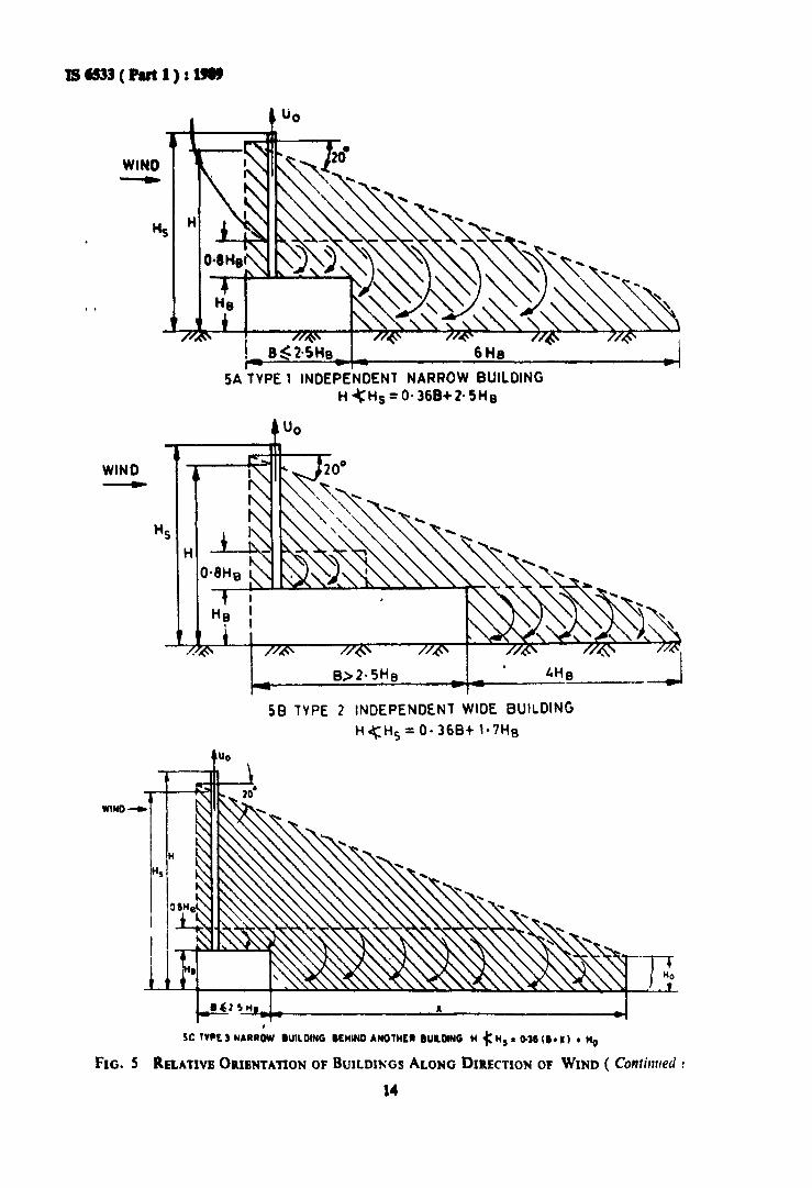
1) For Type 1 H. - 0-36 B + 2-5 H.
2) For Type 2 H. - 0·36 B + 1'1 H.
3) For Types 3 and 4 H. - 0'36 (B + X)+H.
A·3 DesilD hei,ht H of chimney shall beIreater than H. for all tbe types calculatedabove.
whereH - Calculated heipt in m or the
chimaey.
ANNEX A( Clauses 7.2 ad 7_3 )
INRUENCE OF ADODYNAMIC SHADOW ON HEIGHTor CHIMNEY
A-I FAcrORS INRUENCING HEIGHT OFCHIMNEY
A-I.I The height of the chimney shall not beless than the height of the zone of turbulent airlayers formed due to unevenheights of buildingsnear the chimney_ For the purpose of calculation of the minimum heipt of chimney forlce~inl its plume above the turbulent zone, thefoJlowiDI procedure shaJI be adopted:
a) The types of lurroundiul buildiDI structures arODI the direction or wind may bedivided into two ,roups:1) Narrow Blllldlng, where B <2·5 H.;
and2) Wide Building, where B > 2-5 H••
whereB -= width in metres of tbe buildinl
in the downwind direction, andHB - height in metres of the buildiDI.
b) The relative orientation ofbuildiDIS aloDIdirection of wind may be divided iatofour groups:
1) Independent Narrow Building (Type 1)A narrow building in the downwarddirection or which there is DO otherbuilding or obstruction up to a distance of6 H._
2) lndepe.dentWid, Sui/dilll (Type 2)A wide buUdinl in the downwarddirection of which there is no otherbuilding or obstruction up to a distance of 4 H••
3) Nturow Building B,Itl"tl Ano'''', Bulldin,or Obl'r"ctioll ( Ty" 3 ) - A narrowbuildiDI iD the downward direction ofwhich there is another buildin. orobstruction at a distance X such tbatH. < X < lOB•.
4) Wid, Buildin,B,hind A"o''''r Buildi", orOb,truction ( Typ, " ) - A wide buildins in the downward direction of whichthere is another buildina or obstruction at a distance X such that H.< X<8H.,
where
X - distaace in m at which anotherbuildinl or obstruction is Jocated.
13
WINO--......
B~2-5H8 6He
SA TVPE 1 INDEPENDENT NARROW BUILDINGH~Hs=O· 368+ 2- SHe
WIND~
B>2-5 He
58 lVPE 2 INDEPENOENl WIDE BUILDING
H~HS =O· 368+ 1·7HB
WiNO .....
I-
sc tYPE3 NARROW IU'LDING BEHIND AN01HER IUILDING H ~ HS • 0·" (I. X) • "0
FIG. S RELATIVE OlllENTAnON OF BUILDINGS ALONG DIRECTION 0' WIND ( Continued,
14

IS '533 ( Part 1 ) : 1989
Uo
50 TVPE" WIDE BUILDING BEHIND ANOTHER" BUtLDING H~ Hs. Q-31 (B+ X) + Ho
B - width of buildin, in the downwind direction, m X - distance at which another building or obstruc-HB - heiaht of building where the stack is installed, m tion is located, mH - calculated hei.ht of chimney, m No - height of obstruction or building in downwindHI - heisht of aerodynamic shadow, m direction, m
U0 - ejection velocity through stack, m/s
Flo. 5 RBLATIVB OIlIBNTATION 0' BUILDINGS ALONG DIRBCTION 0' WIND
ANNEX B( Claus' 7.3 )
CONSIDERATION OF DISPERSION OF POLLUTANTSON THE HEIGHT OF CHIMNEY
8-1 HEIGHT OF STACK
8-1.1 Tall stacks are necessary to dispersepollutants into the atmosphere in order tomaintain an acceptable air quality standard atthe ground level. Height of stack is a functionof various factors, for example, mass rate ofemission, eftlux velocity, temperature ofeffluent, topographical conditions, meterological conditions of the area where stack islocated and lastly, the air quality standardsthat must be maintained. Based on these parameters, assuming a relatively flat terrain andtemperature of eftluent equal to .the atmospheric temperature, the height of the stack isdetermined from the following formula:
H - [ AM~D.J8CV
where
H - calculated height of stack in m
A :II coefficient of temperature gradient ofatmosphere responsible for horizcnriland vertical mixing of plume
( For tropical zone A-280, andCor semi-tropical zone A == 240),
15
M - estimated mass rate of emission ofpollutant in gIs,
F - dimensionless coefficient of rate ofprecipitation( For gases, F = 1, andfor dust F == 2 if efficiency of dust cat
ching is above 90 percent2-5 if efficiency of dust catching is 75 to 90 percent3-0 if efficiency of dust catching is below 75 percent),
C =- maximum permissible ground level concentration of pollutant in mg/ml
standard temperature and pressure ( stp)(may be taken as 0-5 mg/ml unlessotherwise specified in relevant healthstandards ),
V - Estimated volume rates of emission oftotal flue gases, rn8/sec, and
D = diameter of stack in m,
8-1.2 Recommended height of stacks from theconsideration of pollution of iron and steelplant units is given in Table 3.
B-l.3 Recommended mininmum efflux velocities are given in Table 4.

Taltle 3 alco--._ StaMart a,lpt of Stacb ( lor Proeeu G... ) fro. tileeo.ltlerad_ of PaU1Itloa for ko... Steel Pint Ualtl
( CI.III, B-l.2 )
81 No. V.1t
I Sfnterial plant
2 Blut furnace - stOvel
3 Steel meltia. ahop:a) CODverter.oxYPD blownb) Opeaheartb, oxy..n blownc) ElectricIrc furnaCi
Rolli... mill:
a) Scar8Da machinebl Sualdn. pite ReheatiDl furnaced) ... annealin! furnacee) Continuoul p ckliD.linef) Hot dip ..Iv.niliol line
5 Rotary kUns:a) For lineb) For dolomite
6 Coke oven
7 Thermal power plant
H".t (.)100 to 1$0
fiG to 70
10010030
60 to 70 135 ,45 t4045 ,
J
eo to 8060 to 80
100
120 to 180
a...rbDependin. on SO. loadin. of
exhaust ..S
Check calculations lor unburntcarbon monoxide, if any
Dilcharae point is kept It least3 to 4 m hilher than thebilhclt point of tbe roof
Discharae point i. kept at Ie••t3 to 4 m bilher tban the hipelt point of roof. For picklin.with hydrochloric or sulphuric acid, the efficiency ofclanin. shall be not less than95 per<:ent
For discharain, combustionproducts of battey.
For coal fired boiler, fly ash isthe main hazard. Heiaht maybe checked with SO. loadin.of las also.
Table 4 Reco......aW MIalmulD EtBax Veloclda from AirPoll.tloa Polat of VIe.
( Clause B-l.3 )
IINo.
t2
34
S,It••
Natural draft system
Forced drart system:.) Chimne,s up to 20 m hel.htb) Chimneys from 20 to 45 m heilhtc) Chimneys over 45 m heilht
Induced draft systemOther waste pses and exhaust of industrialventilation systemThermal power plants
V.locltym/s
6
69
12
7'S
IS
2S
NOTE - Use of any weather cowl on the top of stack which restricts the vertical motion of plume is notrecommended. If it is absolutely essential to restrlet entry of rain water into dust system, special weather cowls\\hich will restrict the entry of rain water but allow the pses to meve vertically up\\'ards with the recommendedcfttux velocity may be permitted.
16

--..B-2 L..lt•..., tile P",
B-11 De formula is applicable oaly in CUllof tall stacks, the plume from which is freefrom interference with the air currents producedby nearby tall buildinp.
8-"2.2 De formula assumes OBI, a sinale sourceof air pollution. Where several ltacb arelocated close to each other, the _Iue of Hobtained from the formula has to be increasedsuch that the total arouDd level concentrationat a place from all the stacks for any particular
1IJ8D(PutI):~
pollutat cIoa Dot exceed the air qualityItuclardl.
11-2.3 11ae IonmaIa UI1IIDei the temperat.. orthe sue. to be eqaal to the .~erictemperature. The resDltut hapt or Rack issliptly OD the hillier side.
8-2.4 The IDUim.... coDceatratio. u calculated above is reached at a diItaDce X m frOIDthe chimney, approximately livea by X .. 20 Hwhere H is the heiabt of the chimoey in IDabove the arouad leyel.
ANNEX C
( CIa." 10.1 )
ASH DISPOSAL
cr GENDAL
C-l.l In any coal fired boiler, a particularpercentage of ash which escapes aloDI withthe flue sas will be precipitated due to chanlCin the direction of lue, at the bottom oftbechimney. This will require periodical disposaldepending upon the quantity of ash. For smallboilers, quantity will be very small and thiswill not require elaborate arraDlements whilefor medium and hiah capacity boilers. thequantity will be considerable and will requireseparate arranaements for disposial the ash.
ca ASH DfSI'OSAL SYSTEMS
C-2.1 In case or bi,ser boilers where thequantity is more, a separate arranlement hasto be provided and usually this will be ahopper at the bottom of the cbilDDty and justbelow breach opellinss left Cor lue eoaaeetion. De typical arranaement of tbis isindicated in Fil. 6.
C-2.2 In the case or small boilers, the alh may
be disposed or by ,rovicliDI a hopper on thefoundation itself as Indicated in Fi,. 1.
C·2.2.1 This consists of a hopper with • pteat the bottom which whea a particular welptor volume of ash is collected, will automatically open and discbarac tbe ash into the pit atthe bottom. This ash caD be disposed of bymechanical, pneumatic or hydrauDc systems,dependiq on the system adopted for thedisposal of the ash from the combustioDchamber.
C·2.2.2 In tbe case or the mechanical system,a cODveyor will be provided in the pit so thatthe ash can be rcmovccl aDd loaded in thetrucks outside.
C-2.2.3 In the pneumatic system, asb will beremoved b1 ejector or suc:kiDa by compressedair and dlscharaed into the maill ash disposalsystem.
C-2.2.4 ID the case or hydraulic system, eDouahquantity or water will flush the asb iDto themain ash disposal system.
17

IS '533 ( Part I ) I 1119
TA
50mmf/j GI PIPEWITH 10 mm _ NOZZLES150mm APART
/sHP,l_............HALF SECTION BS
OUNDATIONBOLT
HIMNEVSHELL
liNING
CHIMNEYSHELL
LINING
I
1.
SECTION AI.FlO. 6 HtyOltAl1LIC ASH DIS'OSAL POI CHIMNEY
18

ASH HOPPER
AUlOMATIC Rmut....GAlE (ElTHER 8V THEWEIGHT OR VOlUMEOF ASH)
NNEC-TION TO ASHHOLING SYSTEM
IX FOUNDATION! i ~i CONCRETE
L----l\r----t- --J.,r--_JFIG. 7 ASH RBMOVAL SYSTEM 'OR CHIMNBY
19
IS 6533 ( Part 1 ) : 1989

Bur.au of Indian Standard.
BIS is a statutory Institution established under the Bu,.8Uof indian Standants Act, 1986 topromoteharmonious development of theactivities of standardization, marking andquality certification ofgoodsand attending to connected matters In the country.
Copyright
BIS has thecopyright of all Itspublications. No partof these publications maybe reproduced In anyform without thepriorpermission Inwriting of 81S. this does notpreclude the freeuse,in thecourse ofimplementing the standard, of necessary details, such 88symbols and81zes, typeor grade designations. Enquiries relating to copyright be addressed to theDirector (Publications), 81S.
Review of Indian Standard.
Amendments are issued to standards 8S the need arises on the basis of comments. Standards arealso reviewed periodically; a standard along with amendments Is reaffirmed when such review IndIcates thatno changes areneeded: If thereview Indicates that changes areneeded, It Is taken up forrevision. Users of Indian Standards should Iscertaln thattheyareIn possession of the latest amendments or edition by referring to thelatest Issue of IBIS Catalogue' andIStandards: Monthly Additions'.
This Indian Standard hasbeen developed from Doc: No. SYBDe 7 ( 2609 )
Amendments Issued Since Publication
Amend No. Dateof Issue
BUREAU OFINDIAN STANDARDS
TextAffected
Headquarters :
Manak Bhaven, 9 Bahadur Shah lafar Marg, NewDeihl 110002Telephones: 23230131,23233375,23239402
Telegrams : Manaksanstha(Common toall offices)
Southern : C.I.T. Campus, IVCross Road, CHENNAI600 113
Regional Offices :
Central : Manak Bhavsn, 9 Bahadur Shah latar MargNEW DELHI 110002
Eastern : 1/14 C.I.T. Scheme VIIM,V. t. P.Road. KankurgachlKOLKATA700 054
Northern : SeQ 335-336, Sector 34-A, CHANDIGARH 160022
Telephone
{2323 761723233841
{2337 8499,2337858123378626,23379120
{eo 3843609285
{2254 1218,2254 14422254 2519,2254 2315
Western : Manakalaya, E9 MIDC. Marol, Andherl (East) {2832 9295. 28327858MUMBAI 400093 28327891,28327892
Branches: AHMEDABAD. BANGALORE. BHOPAL. BHUBANESHWAR. COIMBATORE. FARIDABAD.GHAZIABAD. GUWAHATI. HYDERABAD. JAIPUR. KANPUR. LUCKNOW. NAGPUR.NALAGARH. PATNA. PUNE. RAJKOT. THIRUVANANTHAPURAM. VISAKHAPATNAM.
Reprography Unit, 81S, New Delhi, India