is 5347-18 (2002): requirements for orthopaedic implants ... · a disc of the test material is...
TRANSCRIPT

Disclosure to Promote the Right To Information
Whereas the Parliament of India has set out to provide a practical regime of right to information for citizens to secure access to information under the control of public authorities, in order to promote transparency and accountability in the working of every public authority, and whereas the attached publication of the Bureau of Indian Standards is of particular interest to the public, particularly disadvantaged communities and those engaged in the pursuit of education and knowledge, the attached public safety standard is made available to promote the timely dissemination of this information in an accurate manner to the public.
इंटरनेट मानक
“!ान $ एक न' भारत का +नम-ण”Satyanarayan Gangaram Pitroda
“Invent a New India Using Knowledge”
“प0रा1 को छोड न' 5 तरफ”Jawaharlal Nehru
“Step Out From the Old to the New”
“जान1 का अ+धकार, जी1 का अ+धकार”Mazdoor Kisan Shakti Sangathan
“The Right to Information, The Right to Live”
“!ान एक ऐसा खजाना > जो कभी च0राया नहB जा सकता है”Bhartṛhari—Nītiśatakam
“Knowledge is such a treasure which cannot be stolen”
“Invent a New India Using Knowledge”
है”ह”ह
IS 5347-18 (2002): Requirements for Orthopaedic Implants,Part 18: Ceramic Materials Based on Yttria-StabilizedTetragonal Zirconia (Y-TZP) [MHD 2: OrthopaedicInstruments, Implants and Accessories]

IS 5347 (Part 18): 2002ISO 13356:1997
W?mm
Indian Standard
REQUIREMENTS FOR ORTHOPEDIC IMPLANTS
PART 18 CERAMIC MATERIALS BASED ON YTTRIA-STABILIZED
TETRAGONAL ZIRCONIA (Y-TZP)
Ics 11.040.40
@ 61S 2002
BUREAU OF IN DIANSTA ND ARDSMANAK BI+AVAN, 9 BAHADUR SHAH ZAFAR MARG
NEW DELHI 110002
September 2002 Price Group 4
-. I

Orthopedic Instruments and Accessories Sectional Committee, MHD 2
NATIONAL FOREWORD
This Indian Standard (Part 18) which is identical with ISO 13356:1997 ‘Implants for surgery — Ceramicmaterials based on yttria-stabilized tetragonal zirconia (Y-TZP)’ issued by the International Organizationfor Standardization (ISO) was adopted by the Bureau of Indian Standards on the recommendation ofOrthopedic Instruments and Accessories Sectional Committee and approval of the Medical Equipmentand Hospital Planning Division Council.
Standards on basic raw materials and their tests for surgical implants are covered under various partsof IS 5347, A new raw material unalloyed tantalum has been covered in this part of the standard. Thecorresponding test method for unalloyed tantalum sheet rod and wire are also covered in this standard.Since tkle material is used in the manufacturing of surgical implants, the publication of this part of thestandard was felt necessary. This will also help the Indian manufacturers in getting the standard material.
The text of above mentioned ISO Standard has been approved as suitable for publication as IndianStandard without deviations. Certain conventions are, however, not identical to those used in IndianStandards. Attention is particularly drawn to the following:
a) Wherever the words ‘International Standard’ appear referring to this standard, they should beread as ‘Indian Standard’.
b) Comma (,) has been used as a decimal marker while in Indian Standards, the current practiceis to use a point (.) as the decimal marker.
The technical committee responsible for preparation of this standard has reviewed the provision ofISO 3611:1978, ISO 5017-1, EN 843-1:1995, ASTM E 112:1995, ASTM C 323:1956 (1995),ASTM C 373:1988, ASTM C 573:1981 and ASTM C 1161:1990 referred in this adopted standardand has decided that they are acceptable for use in conjunction with this standard.
This Indian Standard has been issued in 18 parts. Other parts of this standard are:
Part 1 General requirements
Part 2 Wrought stainless steel
Part 3 Unalloyed titanium
Part 4 Wrought titanium 6-aluminium 4-vanadium alloy
Part 5 Cobalt-chromium-molybdenum casting alloy
Part 6 Wrought cobalt-chromium-tungsten-nickel alloy
Part 7 Wrought cobalt-nickel-chromium-molybdenum alloy
Part 8 Forgeable and cold-formed-cobalt-chromium-nickel-molybdenum-iron alloy
Part 9 Ceramic materials based on high purity alumina
Part 10 Ultra-high molecular weight ployethylene, powder form
Part 11 Ultra-high molecular weight ployethylene, moulded form
Part 12 Wrought cobalt-nickel-chromium molybdenum tungsten iron alloy
Part 13 Wrought high nitrogen stainless steel
Part 14 Wrought titanium 5-aluminium 2, 5-iron alloy
Part 15 Wrought titanium 6-aluminium 7-niobium alloy
Part 16 Poly (L-lactide) resins and fabricated forms for surgical implants — /n vitro degradationtesting
Part 17 Metallic materials — Unalloyed tantalum for surgical implant applications
For the purpose of deciding whether a particular requirement of this standard is complied with the finalvalue, observed or calculated, expressing the result of a test or analysis, shall be rounded off inaccordance with IS 2: 1960 ‘Rules for rounding off numerical values (revised) ’. The number of significantplaces retained in the rounded off value should be the same as that of the specified value in thisstandard.
IS 5347 ( Part 18 ) :2002
!s0 73356: 1997
Indian Standard
REQUIREMENTS FOR ORTI-K3PAEDIC IMPLANTS
PART 18 CERAMIC MATERIALS BASED ON YllRIA-STABILIZ’ED
TETRAGONAL ZIRCONIA (Y-TZP)
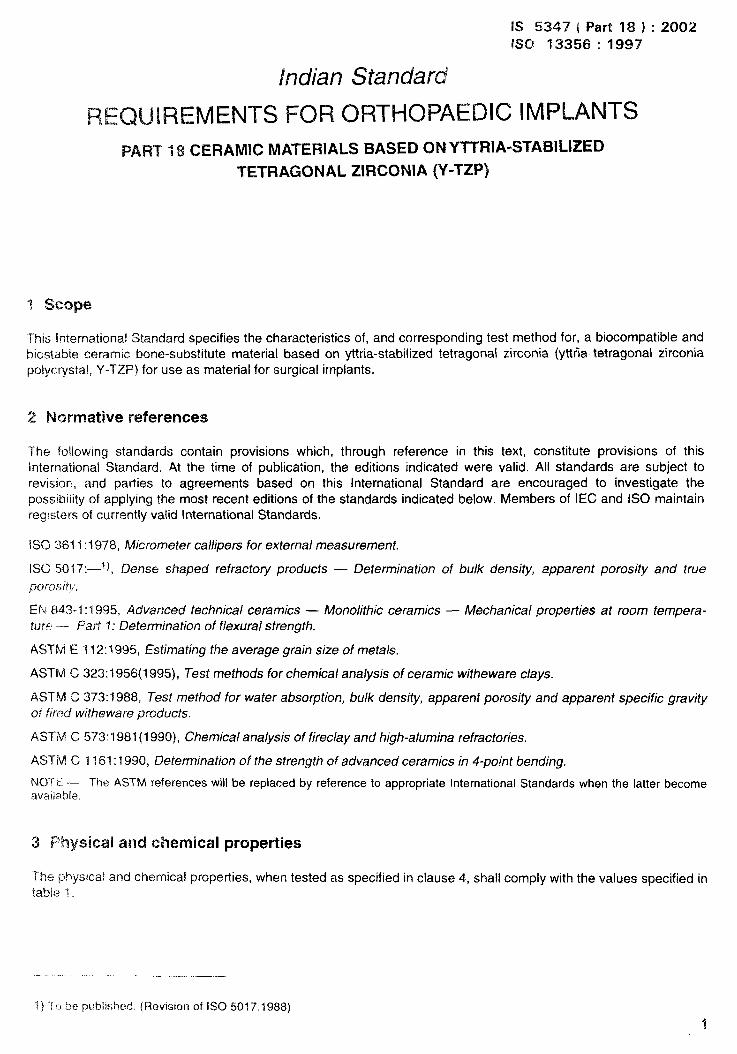
This International Standard specifies the characteristics of, and corresponding test method for, a biocompatible andbiostable ceramic bone-substitute material based on Yttria-stabilized tetragonal zirconia (yttfia tetragonal zirconiapolycxystal, Y-TZP) for use as material for surgical implants.
2 Normative references
The following standards contain provisions which, through reference in this text, constitute provisions of thisinternational Standard. At the time of publication, the editions indicated were valid. All standards are subject torevision, and parties to agreements based on this International Standard are encouraged to investigate thepossibility of applying the most recent editions of the standards indicated below. Members of IEC and ISO maintainregsters of currently valid International Standards.
iSG 3611:1978, M/crorneter ca//ipers for external measurement.
ISO Ml 17:—1 j, Dense shaped refracto~ products — Determination of &xX density, apparent porosity and true
poroslj+’.
EF $43-”1: 19%5, Advanced technical ceramics — Monolithic ceramics — Mechanical properties at room tempera-ture –- Part 1: Determination of flexura/ strength,
AS1-M E “i12:1 ‘395, Estimating the average grain size of metals.
ASTM C 323:1956(1995), Test methods for chemica/ analysis of ceramic witheware c/ays.
AS1 M C 373:1988, Test method for water absorption, bu/k density, apparent porosity and apparent specific gravityof fired nltheware products.
ASTM C 573:1981(1990), Chemica/ ana/ysis of firec/ay and high-a/umina refractories.
ASTM C 1161:1990, Determination of the strength of advanced ceramics in 4-point bending.
NC)TE — The. ASTM references wiil be repiaced by reference to appropriate international Standards when the iatter becomeavaikbie.
3 Physical and chemical properties
The physicai and chemical properties, when tested as specified in ciause 4, shali comply with the vaiues specified intabk 1.
1) TO be published. (Revision of ISO 5017:1988)
K 5347 ( Part 181:2002Km 13356: 1997
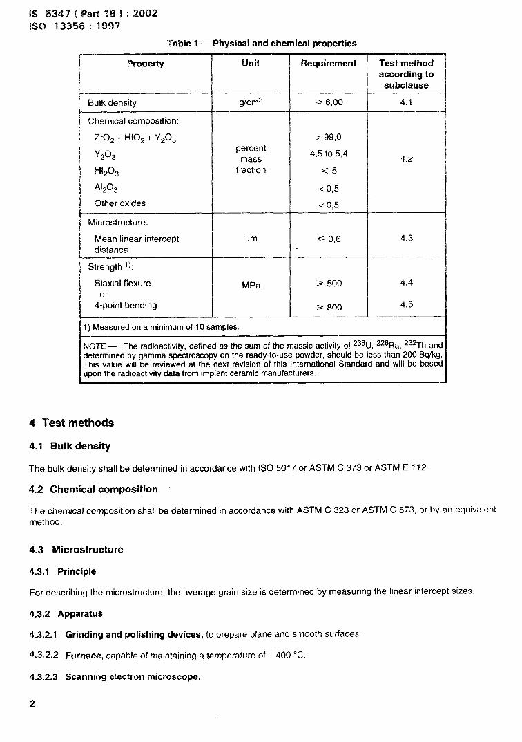
‘Table 1 — Physical and chernicai properties
Property Unit Requirement Test methodaccording to
subclause—.—.— —
Bulk density g/cm3 = 6,00 4.1
Chemical composition:
ZrCJ2+ HfO~ + Y203 >99,0
Y-203percent
4,5 to 5,4mass 4.2
!+203 fraction
A1203 <0,5
Other oxides—
Microstructure:
Mean linear intercept pm, ‘+
== 0,6 4.3
distance
Strength 1):
Biaxial flexure MPa == 500 4.4
or4-point bending 2= 800 4.5
1) Measured on a minimum of 10 samples.—
NOTE — The radioactivity, defined as the sum of the massic activity of 238U, 226Ra, 232Th anddetermined by gamma spectroscopy on the ready-to-use powder, should be less than 200 Bq/kg.This value will be reviewed at the next revision of this International Standard and will be basedupon the radioactivity data from implant ceramic manufacturers.
4 Test methods
4.1 Bulk density
The bulk density shall be determined in accordance with ISO 5017 or ASTM C 373 or ASTM E ?12.
4.2 Chemical composition
The chemical composition shall be determined in accordance with ASTM C 323 or ASTM C 573, or by an equivalentmethod.
4.3 Microstructure
4.3.1 Principle
For describing the microstructure, the average grain size is determined by measuring the linear intercept sizes.
4.3.2 Apparatus
4.3.2.1
4.3.2.2
4.3.2.3
2
Grinding and polishing devices, to prepare p!ane and smooth surfaces.
Furnace, capable of maintaining a temperature of 1400 ‘C.
Scanning electron microscope.

1S 5347 ( Part 18 ) :2002
ISO 13356: 1997
4.3.3 Preparation of test piece
Prepare test pieces of the zirconia ceramic using methods representative of the method of production of parts forsurgery, using the same precursor powder, pressing technique and pressure and firing conditions.
Grind one surface plane, polish it until the percentage of interpretable area is at least 90 Y. and thermally etch at atypical temperature from 1300 ‘C to 1400 “C, for 30 min to 60 min.
Coat the polished surface by sputtering with a thin metallic layer.
NOTE — A gold or a gold-platinum alloy maybe used.
4.3.4 Procedure
Observe the microstructure using the scanning electron microscope at a magnification sufficient to clearly delineategrain boundaries. Using either lines drawn on photomicrographs or stage movement, follow the general procedurein ASTM E 112 to measure the linear intercept sizes of at least 250 grains in total over at least six fields of view onlines sufficiently long to encompass at least 20 grains, taking random orientations of measurement. Calibrate themagnification employed using a certified graticule or grid. Alternatively a calibrated stage micrometer may be used.
4.3.5 Calculation of results
Calculate the mean linear intercept size and the standard deviation from the individual linear intercept sizes.
4.3.6 Test report
The test report shall contain at least the following information:
a) identity of the ceramic material, details of batch number or other codes sufficient to uniquely identify the testpieces;
b) method of preparation of the test pieces, including details of the machining procedure employed to prepare thetest surfaces and of the etching procedure;
c) mean linear intercept size and its standard deviation, expressed in micrometres.
4.4 Biaxial flexural strength
4.4.1 Principle
A disc of the test material is placed between two coaxial rings of unequal diameter and a compressive force isapplied. The force applied at fracture of the test disc is recorded and the fracture stress is calculated.
4.4.2 Apparatus
4.4.2.1 Mechanical testing machine, suitable for applying a compressive load of at least 5 kN at a nominalloading rate of (500 t 100) N/s and equipped to record the peak force applied to an accuracy, of better than 1 O/..
Calibration of the force-measuring device shall be performed according to agreed procedures (e.g. ISO 7500-1);
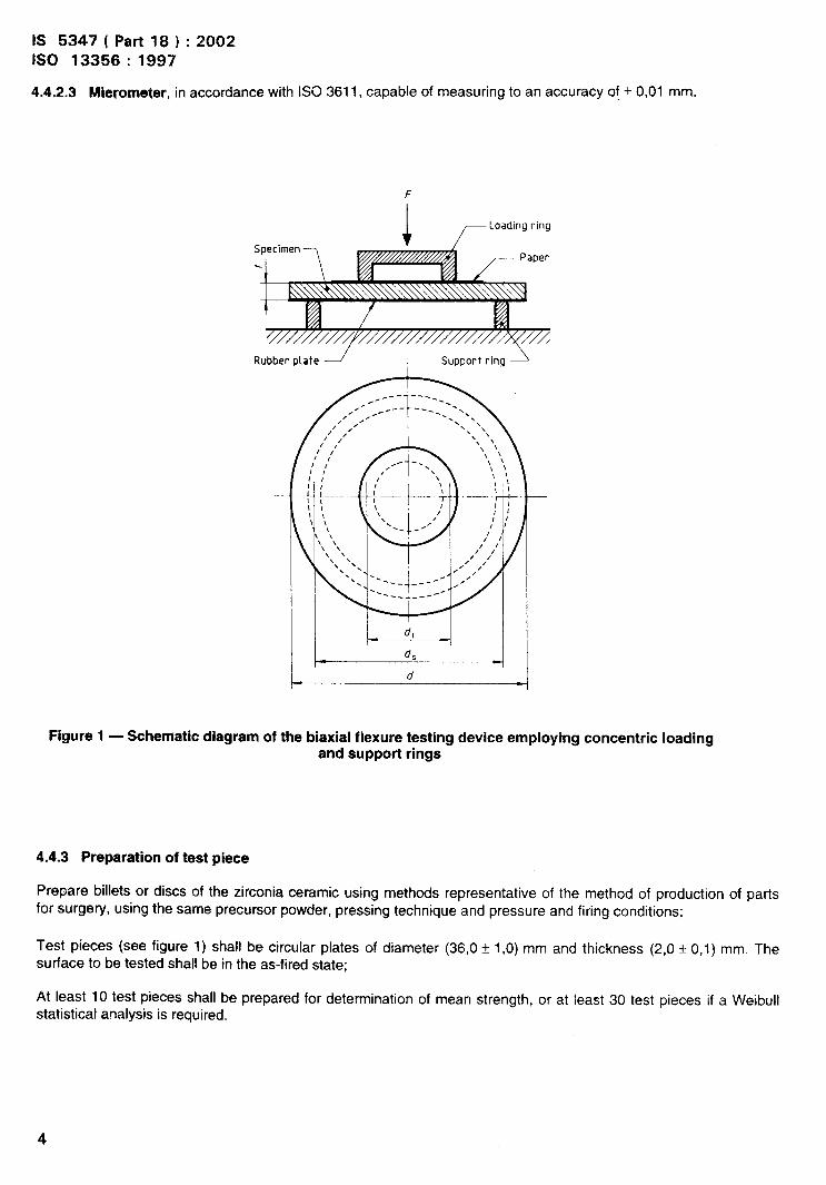
4.4.2.2 Test jig, comprising unequal diameter loading rings and having a geometry typically as shown in figure 1.The jig shall have a support ring diameter of (30* 0,1) mm at the diameter of contact with the test piece, and aloading ring mean diameter of (12 ~ 0,1 ) mm at the diameter of contact with the test piece. The radius of curvature
of the test piece contact surface of the rings shall be (2,0 f 0,2) mm. The jig shall have a means of centrmg theloading and support rings and the test piece on a common axis to within + 0,2 mm. Preferably the rings should bemade of hardened steel (> HV 500 or > HRC 40) in order to minimize damage or roughness caused by fracture ofthe test pieces;
In order to accommodate slight departures from surface flatness of the test pieces, a (0,6* 0,1) mm thick rubber
plate with a Shore hardness of 60 f 5 shall be placed between the support ring and the test piece, and a piece ofpaper shall be placed between the test piece and the loading ring.
3
IS 5347 ( Part 18 ) :2002
1S0 13356:1997
4.4.2.3 M@~ometer, in accordance with ISO 3611, capable of measuring to an accuracy of * 0,01 mm.
F
Rubber plate ~ Support ring JI
\ ,
\ \
I
Figure 1 — Schematic diagram of the biaxial flexure testing device employing concentric loadingand support rings
4.4.3 Preparation of test piece
Prepare billets or discs of the zirconia ceramic using methods representative of the method of production of partsfor surgery, using the same precursor powder, pressing technique and pressure and firing conditions;
Test pieces (see figure 1) shall be circular plates of diameter (36,0 t 1,0) mm and thickness (2,0 f 0,1 ) mm. Thesurface to be tested shall be in the as-fired state;
At least 10 test pieces shall be prepared for determination of mean strength, or at least 30 test pieces if a Weibullstatistical analysis is required.
4
IS 5347 (Part 18): 2002
ISO 13356: 1997
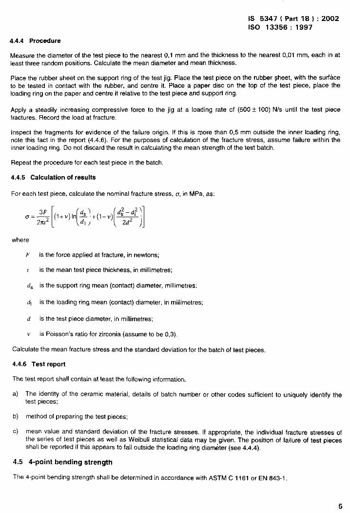
4.4.4 Procedure
Measure the diameter of the test piece to the nearest 0,1 mm and the thickness to the nearest 0,01 mm, each in atleast three random positions. Calculate the mean diameter and mean thickness.
Place the rubber sheet cm the support ring of the test jig. Place the test piece on the rubber sheet, with the surfaceto be tested in contact with the rubber, and centre it. Place a paper disc on the top of the test piece, place theloading ring on the paper and centre it relative to the test piece and suppori ring.
Apply a steadily increasing compressive force to the jig at a loading rate cf (500 t 100) N/s until the test piecefractures. Record the load at fracture.
Inspect the fragments for evidence of the failure origin. If this is more than 0,5 mm outside the inner loading ring,note this fact in the report (4.4.6). For the purposes of calculation of the fracture stress, assume failure within theinner loading ring. Do not discard the result in calculating the mean strength of the test batch.
Repeat the procedure for each test piece in the batch.
4.4.5 Calculation of results
For each test piece, calculate the nominal fracture stress, o, in MPa, as:
a=~[(l+v)’n($l+(l-v)[d::$llwhere
F is the force applied at fracture, in newtons;
t is the mean test piece thickness, in millimetres;
d~ is the support ring mean (contact) diameter, millimetres:
‘I is the loading ring mean (contact) diameter, in millimetres;
d is the test piece diameter, in millimetres;
v is Poisson’s ratio for zirconia (assume to be 0,3).
Calculate the mean fracture stress and the standard deviation for the batch of test pieces.
4.4.6 Test report
The test report shall contain at least the following information.
a) The identity of the ceramic material, details of batch number or other codes sufficient to uniquely identify thetest pieces;
b) method of preparing the test pieces;
c) mean value and standard deviation of the fracture stresses. If appropriate, the individual fracture stresses ofthe series of test pieces as well as Weibull statistical data may be given. The position of failure of test piecesshall be reported if this appears to fall outside the loading ring diarn&ter (see 4.4.4).
4.5 4-point bending strength
The 4-point bending strength shall be determined in accordance with ASTM C 1161 or EN 843-1.
5

IS 5347 ( Part 18 ) :2002
ISO 13356: 1997
The test pieces shall be = 45 mm in length (4,0 10,2) mm in width and (3,0 i 0,2) mm in thickness. The test piece
is supported by two parallel rollers of diameter (5,0 * 0,2) mm. The two rollers shall be positioned symmetrically with
respect to the length of the test piece with their centres (40 * 0,5) mm aparl (outer span).
The two loading rollers shall be symmetrically located with respect to the outer roller and shall have a span of
(20 * 0,2) mm.
6

annex A(informative)
Bibliography
~?j SO 751XJ-Y:1986, Metallic materials –- Verification of static uniaxiai testing machine — Part 1: Tensde testingnachines,
;2] EN 62’3-2:$293, Advanced technical ceramics -— Monolithic ceramics — Gener~l and textura; properties —Pati 2: Determination of density and porosity.
7
Bureau of Indian Standards
i31S is a statutory institution established under the Bureau of Indian Standards Act, 1986 to promoteharmonious development of the activities of standardization, marking and quality certification of goodsand attending to connected matters in the country.
Copyright
BIS has the copyright of all its publications. No part of these publications may be reproduced in any for-mwithout the prior permission in writing of BIS. This does not preclude the free use, in the course ofimplementing the standard, of necessary details, such as symbols and sizes, type or grade designations,Enquiries relating to copyright be addressed to the Director (Publications), 91S.
Review of Indian Standards
Amendments are issued to standards as the need arises on the basis of comments. Standards are also reviewedpcriodicaliy; a standard along with amendments is reaffirmed when such review indicates that no changes areneeded; if the review indicates that changes are needed, it is taken up for revision. Users of indian Standardsshould ascertain that they are in possession of the iatest amendments or edition by referring to the latest issue of<BIS Catalogue’ and ‘Standards: Monthiy Additions’.
This Jndian Standard has been deveioped from Doc : No. MHD 2 (2744).
Amendments Jssued Since Publication
Amend No. Date of Issue Text Affected
BUREAU OF JNDIAN STANDARDS
Headquarters :
Manak Bhavan, 9 Bahadur Shah Zafar Marg, New Deihi 110002 Teiegrams : Manaksanstha
Telephones :3230131, 3233375,3239402 (Common to ali offices)
Regionai Offices : ‘relepilone
Centrai : Manak Bhavan, 9 Bahadur Shah Zafar Marg
{
32376 i7
NEW DELHI 110002 3233841
Eastern : l/i4 C.I.T. Scheme VII M, V. 1. P. Road, Kankurgachi
{
3378499, 33785 6i
KOLKATA 700054 3378626, 337 9i 20
Northern : SCO 335-336, Sector 34-A, CHANDIGARH i60 022
{
603843602025
Southern : C. i.T. Campus, IV Cross Road, CHENNAI 600 i 13
{
254 i2 i6,254 144225425 i9,254 i3 15
Western : Manakalaya, E9 MIDC, Marol, Andheri (East)
{
83292 ‘)5, 8327858
MUMBAI 400093 83278 9i, 8327892
Branches : AHMEDABAD. BANGALORE. BHOPAL. BHUBANESHWAR. COIMBATORE. FARiDABAD.GHAZiABAD. GUWAHAT1. HYDERABAD. JAIPUR. KANPUR. LUCKNOW, NAGPUR.NALAGARH. PATNA. PUNE. RAJKOT. THIRIJVANANTHAPURAM. ViSAKHAPATNAM
Rcpro$rapi]y Unit, BIS, New IXihi, India