is 4758 (1968): methods of measurement of noise emitted by ... · 0.4.1 determination of‘ the...
TRANSCRIPT

Disclosure to Promote the Right To Information
Whereas the Parliament of India has set out to provide a practical regime of right to information for citizens to secure access to information under the control of public authorities, in order to promote transparency and accountability in the working of every public authority, and whereas the attached publication of the Bureau of Indian Standards is of particular interest to the public, particularly disadvantaged communities and those engaged in the pursuit of education and knowledge, the attached public safety standard is made available to promote the timely dissemination of this information in an accurate manner to the public.
इंटरनेट मानक
“!ान $ एक न' भारत का +नम-ण”Satyanarayan Gangaram Pitroda
“Invent a New India Using Knowledge”
“प0रा1 को छोड न' 5 तरफ”Jawaharlal Nehru
“Step Out From the Old to the New”
“जान1 का अ+धकार, जी1 का अ+धकार”Mazdoor Kisan Shakti Sangathan
“The Right to Information, The Right to Live”
“!ान एक ऐसा खजाना > जो कभी च0राया नहB जा सकता है”Bhartṛhari—Nītiśatakam
“Knowledge is such a treasure which cannot be stolen”
“Invent a New India Using Knowledge”
है”ह”ह
IS 4758 (1968): Methods of Measurement of Noise Emitted byMachines [ETD 15: Rotating Machinery]

Indian Standard
IS : 4758 - 1968 ( Reaffirmed 1989 )
METHODS QF MEASUREMENT OF
NOISE EMITTED BY MACHINES
( Fourth Reprint DECEMBER lW5 )
UDC 534,837
BUREAU OF INDIAN STANDARDS MANAK IIII.\V~\N, 9 Ilr\li.\l)Ui< SIlAl I %t’,:l;.\li RI.\l;(;
NI:LV blirxr 1 iOOl):!
IS : 4758 - 1968 ._
Indian Standard METHODS OF MEASUREMENT OF
NOISE EMITTED BY MACHINES
Acoustics Sectional Committee, ETDC 27
Chairman Representing
DR k. PANCI~OLY National Physical Laboratory ( CSIR ), New Delhi
MnnbCrS
SIIRI A. N. AHUJA Ahuja Radios, New Delhi SHRI I. S. AHUJA ( Altcrnatc~)
SHRI G. S. BOLINA G. W. Balkar & Co, Jullundur SHRI S. C. I~RANI The Radio Electronics & Television Manufacturer’s
Association, Calcutta SHRI R. K. JAIN ( Alternate )
SHRI H. JO~A RAO State Broadcasting Department, Government of Andhra Pradesh
SHRI B. G. KALE Railway Board ( Ministry of Railways ) LT-COL S. D. MAINI Directorate General of Inspection (Ministry of
Defence ) SHRI P. XRISHNAMURTHY RAO (Alternate)
SHRI G. B. MEEMAMBI Posts & Telegraphs Department, New Delhi SHRI .I. S. MON~A All India Radio Merchants’ Association, Bombay
S&r V. J. BHATT ( Alternate ) ( Bombay )
SHRI D. N. CHA~JDI~URI ( Alternate ) ( Calcutta )
SHRI L. S. V. EA~WAR (Alternate )
SHRI &~~;I?,,,,, S&I B. P. GHORH ( Alternate )
National Test House, CalcutLa
SHRI M. S. NARAYANAN Directorate General of Defence Research & Develop- ment ( Ministry of Dcfence )
DR B. S. RAXAKZISHNA Indian Institute of Science, Bangalore RESEARCH ENGINEXI~ Directorate General of ‘411 India Radio
DR ( SMT ) C. K. KESAVAN ( Alternate ) SHRI M. SAN~AR~LINGAM Directorate General of Supplies & Displjsnls
( Inspection Wing ) Drt D. L. SUBRAHMANYAM Central Electronics Enginxring Research Institute
( CSIR 1. Pilani ’ _
/‘mm- SHIU K. D. PAVATF. ( Alternate)
SHRI Y. S. VENKATRSWARAN. Director General. IS1 ( Ex-qficio Member ) ’ Director ( Elec tech )
Secretaries
SHKI N. SI~INIVASAN Deputy Director ( Elec tech ), IS1
SHRI S. MIX~IOPADIIYAY Assistant Dirrctor ( Elec tech ), ISI
BUREAU OF INDI’AN STANDARDS MANAK BHAVAN, 9 BAHADUR SHAH %AY.\lZ MARC
NEW DELHI 1100X?
IS : 4758 - 1968
Indian Standard METHODS OF MEASUREMENT OF
NOISE EMITTED BY MACHINES
0. FOREWORD
0.1 This Indian Sta.ndard was adopted by the Indian Standards Institution on 3 September 1965, after the draft finalized by the Acoustics Sectional Committee had been approved by the Electrotechnical Division Council.
0.2 This standard concerns with the procedures followed in the objective measuremeqts of noise emitted by machines. These procedures are not necessarily applicable to n&se of an impulsive character.
0.3 This standard describes the general principles of methods of measurc- ments of machinery noise based on lvhich individual standards may be formulated. The specific standard covering methods of measurement of noise of the various types of machines will have to select the most suitable method having regard to the size of the machine and its application. All the necessary particulars to enable a result to hr obtained with the required accuracy will be given in these standards.
0.4 The measuremerit of the physical characteristics of the noise of machines has the following four objects:
a) To verify that the noise of a givrn machinr conforms to a c’ertain standard,
b) To make a comparison betjveen the nnisc> Prnit ted by machines huilt to the same specification,
c: To make a comparison between the noise emitted by difkent machines, and
dj To determine the noise received at a distance.
The four aims specified above are achieved by determining the acoIls- tic noise power radiated by the machine as well as the directivity, these quantities being measured a s a function of the frequency. Determination of the acoustic po\ver shocld thus be the preferred mc~thod for the measure- ment of the noise of machines. The different methods of measuring acoustic power are given in Appendices A to C.
0.4.1 Determination of‘ the po\ver and that directivity, however, leads to the siting of the points of measurement sufFic,iently removed ti-om the machine for the conditions of prnpagntion by. progressive knaves to be established. It ii :~.IM n~essar~~ that at this site, the reflections from the walls of the preiui<cs &all have no cf%t:t. This quires premises of relativelv large dnnt~nsions ~r~q~;l~d \vith tlx)se of the machine. with ver) abso:ber;t lvalls.
2

0.4.3 It Inay also IX possilJl(~ to use sc~mi-1.c,vcrf)crarlt spaces lout this 1nethOd call ~iYJVidC Olll;i the, limited infi)rmation on the dircc.tivity of ac.oustic: radiation and very rough cstirnation of the acoustic powcl-.
0.4.4 Whilr the: v \\.iil be 110 diflicult)? to provide nczcssary acoustic cnvi:-onrncnt fi)r small rnac,hincs, it may not always br possible to achicvc the ncc’rssary contlitiolls Li,r larq: machines, special installation condition of‘ the machine may be rcquirc:d. ‘I’hc!sc conditions cannot always 1K met particularly fbr lar,qf: rnachitics. It rrlay not also be possil~lc to bring the rnachinc: to :l roo1n snital)lc fbr thr d~tcrrnirlarion of the acousl ic l’“WW. Hcnw. IIW is of‘tcbn nladtl of a sirnplific~d mt~thod in which sounc! pressure mt:asIIretnerit5 arc carr kd out at certain rncasurrrnc~nt points suit- ably spread arorind tile outer casing of the machine, suilicicntly close to the machine t.0 &viatc the effixt of ttrr sound reflections. Such a method enables the objecl C a 1 to lye achicvcd with thct desired precision, the dimensions of the rnachintr lying goncrally sufiicifmtly well-dcfincd, but it does not enable ol~j~f+; ( c) and cd ) to h obtained. It is, however, possible for the acoustic conditions at a distance to be evaluated approximately on the baG\ oi pressure measur~:rncnts carried out in the vicinity oi‘ the rnachinr 1)~ takin,g illto ac.cnrlnt the surface on which the measurements have been carried out.
0.5 ‘This ?tand<ii d ii)llous clasc~ly 1 SO Recommendation 495 ‘ C,kr!c~~ al rcyuirernents fi)r :irc: prq~aral ion of test codes for measrlring the nois{* einittcd bv mac:h!rii~\ ’ StandardizBtiox~.
issllecl liv the lnterndrionai Organization for
0.6 In reporting the resrllt of a test made in accordance with this stz~~ndard, Ii‘ :he fi;lal value, obscrvcd or calculated, is to be rounded or, it shall be done in accordance \zith IS : Z- 1960*.
1. SCOPE
1.1 ‘I’his standard deals with the procedures to be followed in the objective measurement of the noise emitted by. machines. These procedures are not necessarily applicable to noise of an mlpulsive character.
2. TERMINOLOGY
2.0 For the purpxe of this standard, the following definitions shall apply.
*R&s for rounding off numerical values ( re&d )
3

PS:4758-1968
2.3 Sound Power Level-Ten times the common (Briggsian j logarithm the ratio of a given sound power to a stated reference power.
2.4 Machine -- rbly sound source of which the acoustical characteristics are to be meast1rc.d.
2.5 Prescribed Surface ---A hypothetical surface surrounding the machine as given in the individual standard and over which the measurements are assumed to be made. Its area is calculated as laid down in the individual standard.
2.6 Equivalent Hemisphere - Hypothetical hemisphere having the same area as the prescribed surface.
2.7 Reference Radius -Radius ( measured from the centre of the eclui- valent hemisphere :: as given in the individual standard, to which all the reslllts of uieasrueirients made on machines of the same category (tested according to the same standard 1, are reduced.
3. GENERAL
3.1 fustallation and Operation of the Machine ---The acoustic radia- tion of the rilachine can depend on its insta!lation, particularly when the machine is one of small climensirn~~. The condition of installation and the conditions of operation of the machine during the test shall he included in the individual spccificatinn.
3.2 Qyantities to be Measured-Depending on the purpose of the measurement, iiature of the noise source, and the character of the sound field, one or both of the following quantities should he measured:
a) Sound level ( it is recommended that the weighting network A will he adopted ‘I, and
13) So!ind pressure level in frequency hands of given width.
‘Specifration for scwxi lcvcl meters for ,qeneral purposes \\se.
4

IS : 4758 -1!%8
3.2.1 Since in all cases a pressure microphone will be used, the result of the measurements will he band sound pressure level or sound level values.
NOTE 1 -When the spectral distribution of the noise is well known, a measure- mrnt of wide band sound pressure level or sound level may suffice.
4 NOTE 2 - Any determination of the spectral distribution of the noise should be in frequency bands corresponding to those specified in IS : 2264-1963*.
3.3 Measuring Equipment-A sound level meter (see IS : 3932-1966t) or a frequency analyzer or both shall be used as specified in the relevant standard.
3.3.1 The measuring equipment shall be calibrated against acoustic standards at suitable intervals.
3.4 Measuring Positions - In the individual standard, the sound pressure level measuring positions are to be clearly laid down.
4. METHODS OF MEASUREMENT
4.1 The accurate determination of the acoustic power of a machine (see 0.4) has to be performed either as a far-field sound pressure level measurement under hemispherical radiation or free-field conditions, or as a sound pressure level measurement in a reverberant room under diffuse field conditions. ‘In cases where it is difficult to take sound pressure level measurements under these conditions, the measurements may have to be performed under semi-reverberant conditions (see Appendix C), or near- field measurements (see Appendix D) be made.
4.1.1 The following four methods are available for the determination of acoustic noise power of the machine and/or the sound pressure level of the noise ernitted:
a)
b)
c)
Hemispherical radiation and free-jield methods -The basic principle of this method and evaluation of the radiated acoustic noise power and its directivity are described in Appendix A;
D$use-Jield method- The basic principle of this method and evalua- tion of acoustic noise power are described in Appendix B. This method does not provide information on the directivity sf the acoustic radiation. Since the degree of diffusion is dependent upon the nature of the noise source, this method is not recommended for machines the noise from which contains prominent components;
Semi-reverberant method-The basic principle of this method is described in Appendix C. This method provides only limited information on the directivity of the acoustic radiation and a rough calculation of radiated acoustic noise power; and
*Pdeferred frequencies for acoustical measurcmextts. TSpecification for sound level meters for general purposes use.
5

rs : 4758 - 1968
d) ,Vear-jielti method- In this method the sound pressure level measure- ments only are made close to the machines. Details of this method along with the required calculations and evaluation of approximate acoustic noise power are given in Appendix D. This method is particularly applicable to large machines (see 0.4 j.
42 Correction for Background Noise-The background noise read- ings when the machine is not on test should be determined using the same filters and at the same points as for the test. The readings at each point with the machine on test ought to exceed those due to the background noise alone by at least 10 dB.
4.2.1 When the differences are less than 10 dB, corrections as given below shall be applied :
dB XNCREASE IN LEVEL dB TO BE SUBTRACTED PRoDmEn BY THE MACHINE FROM THE MEASURED VALVE
(dB) (dB) 3 4-5 ; 6-9 1
When corrections are applied the corrected levels should be reported in brackets.
4.2.2 When the increase is less than 3 dB, measurements in general cease to have any significance.
5. PRESENTATION OF TEST RESULTS
5.1 The test report shall give the following information in all cases:
4 b)
9 4
e)
f 1
Reference to individual standard, if any;
Description of the machine and of its conditions of installation and operation;
Description of the test environment and location of the machine;
Meteorological conditions, if appropriate, for example, ambient temperature, relative humidity and barometric pressure;
Description of measuring apparatus used;
NOTE 1 -When a sound level meter is used, the type employed and the weighting~networlc used should be stated.
NOTE 2 -When a freqllcncy analyzer is used, the band widths and centrr frequencies should k-stated.
Position of measuring points;
6

IS : 4756 - 1968
g) Results of sound pressure level measurements;
h) Background noise levels;
j) Sound pressure level values corrected for background noise, if necessary:
k) When required, the calculated octave band sound power levels;
m) When required, the sound pressure level at the reference radius or reference surface corrected as for free-field conditions; and
II) In the case of measurements in an ~anechoic environment, when required, the directivity index as calculated by the method of Appendix A.
NOTE- Values of the directivity index at intervals of 30’ are generally sufficient.
5.1.1 Additional Information to be Given for .Near-Field Sound Pressure Level i\lea.swements
a) Description of the prescribed surface and equivalent hemisphere.
b) Results of sound pressure level measurements, either average or individual, as specified in the individual standard.
c ) Effect, if any, of environment.
d) Extrapolation of the results to the reference radius specified in the individual standard by the method given in Appendix D.
6. CHOICE OF METHOD
6.1 ‘The objects specified in 0.4 are achieved by determining the acoustic power radiated by the machine as well as the directivity. Hence the method that permits the determination of acoustic power is recommended. However, the choice of method depends on the size of the machine and its application.
6.1.1 The methods specified in 4.1.1 (a) enable the determination of the acoustic noise power of the machine and its ~directivity (physical proper- ties of the machine noise) and the calculation of the sound pressure level in other distance or other rooms.
If the directivity is not pronounced or there are no great variations from one machine to another, it may be preferable to determine the acoustic power from measurements in a diffuse field as specified in 4.1.1 (b) . In this case since the characteristics of the reverberant enclosure generally vary with frequency, it is usually necessary to analyze the noise in frequency bands.
These two methods are preferred methods.
7

IS : 4758-1968
6.1.2 In certain cases, the method specified in 4.1.1 (c) which is less accurate may be acceptable. Determination of acoustic power by this method is often less precise.
6.1.3 When measurements according to 4.1.1 (a) to ( c ) are difficult to perform, measurement of the sound pressure level close to the machine and where appropriate, the determination of sound pressure level at the refer- ence radius, in accordance, with 4.1.1 (d) may have to be made. These may be the only measurements possible when difficulties are encountered with reflecting surfaces or background noise. Such measurements permit correct comparisons to be made between similar machines built to the same specifications but make possible only an approximate determination of the acoustic power or the sound pressure level at a distance.
APPENDIX A
[C&me 4.1.1 (a)]
DETERMINATION OF ACOUSTIC POWER AND DIRECTIVITY INDEX UNDER HEMISPHERICAL RADIATION AND
FREE-FIELD CONDITIONS
A-I. PRINCIPLE OF MEASUREMENT
A-l.1 The determination of the power and the directivity requires the siting of measurements points sufficiently remote from the machine for the conditions of propagation of progressive sound waves to be estab- lished. There should be no reflected waves at the measurement points and this requires premises with sufficiently absorbent walls and dimen- sions large compared with those of machine Any effect of the surround- ings or near-field effects will be made apparent by measuring over two surfaces and checking if the sound pressure varies inversely as the square root of the ratio of surface areas. A ratio of areas of 2 or 4 is recom- mended, corresponding to -3 and -6 dB respectively. The results of such check measurements should be stated.
A-2. DETERMINATION OF ACOUSTIC POWER
A-2.1 i%ny machines are mounted on or near a reflecting floor plane. Under these conditions, in the absence of reflections from other surfaces of the environment and in the absence of absorption in the surroundings, the sound power level may be determined. A hemisphere is marked out around the machine and the sotmd power Ievel calculated as follows:
IS:4758-1968
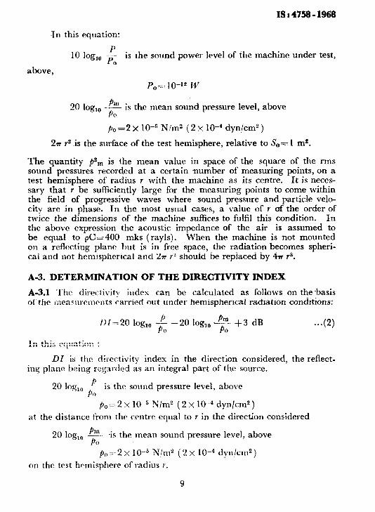
In this equation:
10 log,, ; is the sound power level of the machine under test, 0
above,
P 20 log,, -.z PO
is the mean sound pressure level, above
p0 = 2 x 1 O-” N/m3 ( 2 x 1 O-4 ~dyn/cm” )
2n r2 -is the surface of the test hemisphere, relative to &,= 1 mz.
The quantity &, is the mean value in space of the square of the rms sound pressures recorded at a certain number of measuring points, on a test hemisphere of radius Y with the machine as its centre. It is neces- sary that Y be sufficiently large for the measuring points to come within the field of progressive waves where sound pressure and particle velo- city are in phase. In the most usual cases, a value of Y of the order of twice the dimensions of the machine suffices to fulfil this condition. In the above expression the acoustic impedance of the air is assumed to be equal to pC=400 mks (rayls). When the machine is not mounted on a reflecting plane but is in free space, the radiation becomes spheri- cal and not hemispherical and 2rr yZ should be replaced by 4n r2.
A-3. DETERMINATION OF THE DIRECTIVITY INDEX
A-3.1 ‘I‘he directivity index can be calculated as fOllows on the~basis of the measllrcmvnts carried out under hemispherical radiation conditions:
1)1=20 log,, f -2Olog,,,++3 dB . . . 0 0
In this equation :
DI is the directivity index in the direction considered, the reflect- ing plane being regarded as an integral part of the source.
20 log,, P p,,
is thr sound pressure level, above
pO= 2 x lo-m5 N/m2 (2 x 1O-4 dyn/ctn*)
at the distance from the centre equal to Y in the direction considered
20 log,, E?J- PO
is the mean sound pressure level, above
p,=2 :< 1O-5 N!m2 ( 2 x 1O-4 dyn/cm2)
on the test hemisphere of radius r.
9
IS :-4758 - 1968
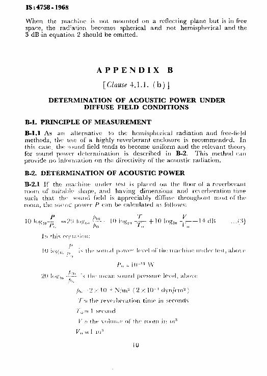
When the machine is not mounted on a reflecting plane but is in free space, the radiation becomes spherical and not hemispherical and the 3 dB in equation 2 should be omitted.
APPENDIX B
[ &?Lse 4.1.1. ( h ) ]
DETERMINATION OF ACOUSTIC POWER UNDER DIFFUSE FIELD CONDITIONS
B-l. I’RINGIBLE OF MEASUREMENT
B-l.1 As arr alternative to the hemispherical radiation and free-field methods, the use of a highly reverixrant enclosure is recommended. In this case the> ~:+)untl field tends to become uniform ant1 the relevant theory for sound povver determination is descrilwd in B-Z. This method can provide no inlijr triatiun on the directivity of the acoustic radiation.
B-2. DETERMINATION OF ACOUSTIC POWER
itJ
IS :4758-1968
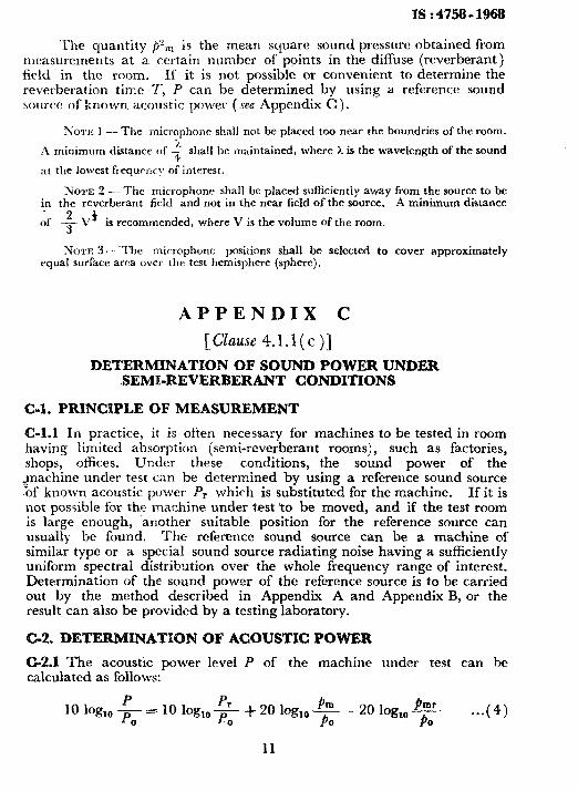
The quantity p”,,, is the mean square sound pressure obtained from measurements at a certain number of ppints in the diffuse (reverberant) field in the room. If it is not possible or convenient to determine the reverberation time 7; P can be determined by using a reference sound source of known acoustic power (see Appendix C ).
NOTE 1 -- The microphone shall not be placed too near the boundries of the room.
A minimum distance of G shall be maintained, where L is the wavelength of the sound
at the lowest frrqurncy of interest.
NOTE 2 - The microphone shall be placed sufficiently away from the source to be in the reverberant field and not in the near field of the source. A minimum distance
,f 2 V+ 3
is recommended, where V is the volume of the room.
NOTE 3 --The microphone positions shall be selected to cover approximately equal surface area over lhr: test hemisphere (sphere).
APPENDIX C
[CZause 4.1.1(c)]
DETERMINATION OF SOUND POWER UNDER .SEMkREVERBERANT CONDITIONS
C-l. PRINCIPLE OF MEASUREMENT
C-l.1 In practice, it is often necessary for machines to be tested in room having limited absorption (semi-reverberant rooms), such as factories, shops, offices. Under these conditions, the sound power of the
pachine under test can be determined by using a reference sound source ‘of known acoustic power Pr which is substituted for the machine. If it is not possible for the machine under test YO be moved, and if the test room is large enough, another suitable position for the reference source can usually be found. The reference sound source can be a machine of similar type or a special sound source radiating noise having a sufficiently uniform spectral distribution over the whole frequency range of interest. Determination of the sound power of the reference source is to be carried out by the method described in Appendix A and Appendix B, or the result can also be provided by a testing laboratory.
G-2. DETFJkMlNATION OF ACQUSTK POWER
C-2.1 The acoustic power level P of the machine under test can he calculated as follows:
10 log,, $ PC = 10 log,, p, + 20 log,, Pm -&- - 20 log,, 0 F . ..( 4)
11

x:4758-1968
In this equation:
P 10 log,, I-’ is the sound power level of the machine under test,
0 above
IJo= lo-*2 w
10 log,, + is the sound power level of the reference source, above 0
p”= lo-‘* w
20 log,,, -:E is the mean sound pressure level of the machine under 0
test, ~above _
p,=2 x 1O-5 N/m2
20 log,, p$= is the mean sound Cl
above
( 2 x 1 O-4 dyn/cm* )
pressure level of the reference source,
p0=2 x 1O-5 N/m2 (2 x 1O-4 dyn/cm2)
The quantities Pan and p& are the space averages of the mean square sound pressures recorded at a certain number of points on the test hemi- sphere of radius r in the semi-reverberant room, with the machine as its centre. The radius r is chosen as in the case for hemispherical radiation or free-field conditions (Appendix A). The measuring points are chosen in the same way for the reference source and for the machine under test.
C-2.2 In many cases a region of the sound field can be found where the sound pressure level beyond the distance Y does not vary appreciably with position. In that event, the above equation can still be used to calculate P. The quantities p2m and p2,r,r then represent the mean values of the* squares of the rms sound pressures recorded at a certain number of points in the reverberant field of the test room. This procedure can also be followed in a reverberant room (see Appendix B ).
APPENDIX D
[Clause 4.1.1 (d) ]
NEAR-PIELD SOUND PRESSURE LEVEL MEASUREMENT
D-l. MEASUREMENT
D-l.1 Prescribed Surface--A surface as simple as possible and whose area can be calculated easily is to be marked out round the machine con- forming approximately to the external casing. This surface and its
12
IS : 4758 - 1968
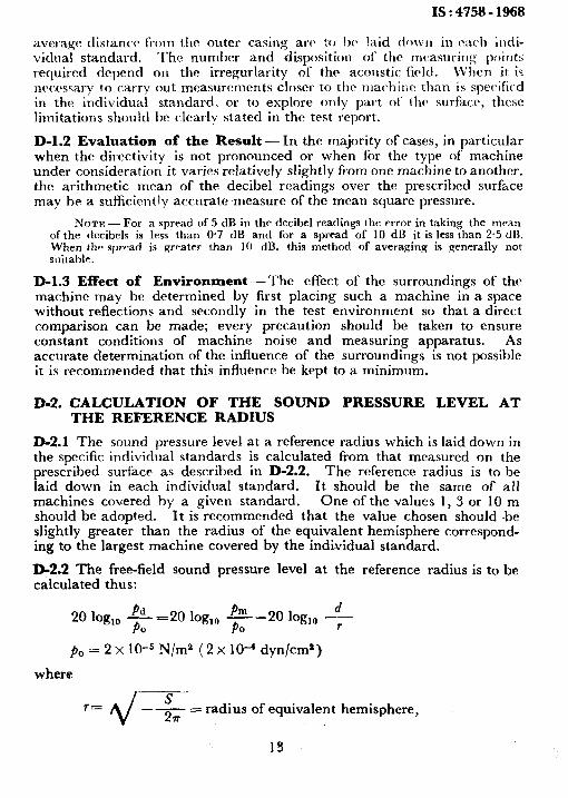
average distanW from the outer casing arch :o 1~ laid do~v11 in r;lch illdi- vidnal standard. The number and disposition of the rncasurillg points required depend on the irregurlarity of thr acorlstic. lic~ltl. When it is nc’ctbssary to carrv out measurements closer to the machine than is specific-d in the individual standard, or to explore only part of’ lhc surface, these limitations should be clearly stated in the test report.
D-l.2 Evaluation of the Result - In the majority of cases, in particu1a.r when the directivity is not pronounced or when for the type of machine under consideration it varies relatively slightly from one machine to another. the arithmetic mean of the decibel readings over the prescribed surface may he a sufflcicntly accurate measure of the mean square pressure.
NOTE - For a snread of 5 dB in thr decibel readinm the error in takiw the mean of the decibels is les’s than 0.7 dB and for a spread-of 10 dB it is less ‘;han 2.5 dB. When thv spread is g-water than 10 dB. this method of averaging is generally not witahle.
D-l.3 Effect of Environment-l’he effect of the surroundings of the machine may he determined by first placing such a machine in a space without reflections and secondly in the test environment so that a direct comparison can be made; every precaution should be taken to ensure constant conditions of machine noise and measuring apparatus. As accurate determination of the influence of the surroundings is not possible it is recommended that this influence he kept to a minimum.
D-2. CALCULATION OF THE SOUND PRESSURE LEVEL AT THE REFERENCE RADIUS
D-2.1 The sound pressure level at a reference radius which is laid down in the specifir individual standards is calculated from that measured on the prescribed surface as described in D-2.2. The reference radius is to be laid down in each individual standard. It should be the same of all machines covered by a given standard. One of the values 1, 3 or 10 m should be adopted. It is recommended that the value chosen should be slightly greater than the radius of the equivalent hemisphere correspond- ing to the largest machine covered by the individual standard.
Da.2 The free-field sound pressure level at the reference radius is to be calculated thus:
20 ‘O&o +- =20 log,, d
0 +- -20 log,, -
r
PO = 2 X 10e5 N/m2 ( 2 x lo-’ dyn/cm’)
where
= radius of equivalent hemisphere,
13
IS : 4758-1968
S = area of prescribed surface,
d = reference radius,
f.~,,, = mean sound pressure over the prescribed surface, and
pd = sound pressure at the reference radius.
D-3. APPROXIMATE EVALUATION OF THE SOUND POWER
D-3.1 In certain cases it is possible to arrive at an approximate evalua- tion of the sound power starting from the sound pressure level at the measuring distance or the reference radius (see D-2 and Appendix A).
NOTE- In the case of hemispherical radiation, the numerical value of sound power level would be 8, 18 or 28 dB greater than the sound pressure level at the reference distances of 1, 3 and 10 m respectively.
14

BUREAU OF INDIAN S
Headquarters:
Manak Bhavan, 9 Bahadur Shah Zafar Marg,
Telephones: 331 01 31, 331 13 75
Regional Offices:
TANDARDS
NEW DELHI 110002 Telegrams: Manaksanstha ( Common to all Offices)
Telephone
Central Manak Bhavan, 9 Bahadur Shah Zafar Marg.
I
331 01 31 NEW DELHI 110002 331 1375
*Eastern : 1 /14 C. I. T. Scheme VII M, V. I. P. Road, 36 24 99 Maniktola. CALCUTTA 700054
Nortnern : SC0 445-446, Sector 35-C,
I
21843 CHANDIGARH 160036 3 16 41
(
41 24 42 Southern : C. 1. T. Campus, MADRAS 600113 41 25 19
41 2916 twestern : Manakalaya, E9 MIDC. Marol, Andheri ( East ), 6 32 92 95
BOMBAY 400093
Branch Offkes:
‘Pushpak’, Nlurmohamed Shaikh Marg, Khanpur,
I
2 63 48 AHMADABAD 380001 2 63 49
$Peenya Industrial Prea 1st Stage, Bangalore Tumkur Road 38 49 55 BANGALORE 560058 I 38 49 56
Gangotri Complex, 5th Floor, Bhadbhada Road, T. T. Nagar, ’ 6 67 16 BHOPAL 462003
PIot No. 821’83. Lewis Road, BHUBANESHWAR 751002 5 36 27 53j5. Ward No. 29, R.G. Barua Road, 5th Byelane, 3 31 77
GUWAHATI 781003 5-8-56C L. N. Gupta Marg
HYDERABAD 500001 Nampally Station Road )e 23 1083
R14 Yudhister Marg. C Scheme, JAIPUR 302005 {
6 34 71 6 98 32
117/418 B Gavodaya Nagar, KANPUR 238005 {
21 68 76 21 82 92
Patliputra Industr;al Estate, PATNA 800013 6 23 05 T.C. No. 14/142%. Universitv P.O.. Palayam
TRIVAND‘RUM 695035 16 21 04 ‘l-6 21 ‘97
inspection Officzes ( With Sale Point ):
Pushpanjali, First Floor, 205-A West High Court Road, 2 54 71 Shankar Nagar Square, NAGPUR 440010
Institution of Engineers ( lndia ) Building, 1332 Shivaji Nagar, 5 24 35 PUNE 411005
*Sales Office in Calcutta is Street. Calcwa 700072 at 5 Chowringhee Approach, P. 0. Princep 23 66 00
tSales Office in 8ombay is at Novelty Chambers, Grant Road, 69 65 28 Bombay 400007 :
:Sales Offire in Bangalore Bangalore 560002
is atcunity Building, Narasimharaja Square, 22 36 71
Keprography Unit, BIS, New ~Delhi, Indz