is 335 (1993): new insulating oils · for the maintenance and supervision of insulating oils...
TRANSCRIPT

Disclosure to Promote the Right To Information
Whereas the Parliament of India has set out to provide a practical regime of right to information for citizens to secure access to information under the control of public authorities, in order to promote transparency and accountability in the working of every public authority, and whereas the attached publication of the Bureau of Indian Standards is of particular interest to the public, particularly disadvantaged communities and those engaged in the pursuit of education and knowledge, the attached public safety standard is made available to promote the timely dissemination of this information in an accurate manner to the public.
इंटरनेट मानक
“!ान $ एक न' भारत का +नम-ण”Satyanarayan Gangaram Pitroda
“Invent a New India Using Knowledge”
“प0रा1 को छोड न' 5 तरफ”Jawaharlal Nehru
“Step Out From the Old to the New”
“जान1 का अ+धकार, जी1 का अ+धकार”Mazdoor Kisan Shakti Sangathan
“The Right to Information, The Right to Live”
“!ान एक ऐसा खजाना > जो कभी च0राया नहB जा सकता है”Bhartṛhari—Nītiśatakam
“Knowledge is such a treasure which cannot be stolen”
“Invent a New India Using Knowledge”
है”ह”ह
IS 335 (1993): New insulating oils [ETD 3: Fluids forElectrotechnical Applications]


IS 335 : 1993
qTr&Tm
?-wkTaer;r*~-m ‘3
( d8T ~??%VJl )
Indian Standard
NEW INSULATING OILS- SPECIFICATION ( Fourth Revision )
Third Reprint SEPTEMBER 1998
UDC 621.315.615.2
September 1993
Q BIS 1993
BUREAU OF INDIAN STANDARDS MANAK BHAVAN, 9 BAHADUR SHAH ZAPAR MARG
NEW DELHI 110002
Price Group 6
Fluids for Electrotechnical Applications Sectional Committee ET 03
FOREWORD
This Indian Standard ( Fourth Revision ) was adopted by the Bureau of Indian Standards, after the draft finalized by the Fluids for Electrotechnical Applications Sectional Committee had been approved by the Electrotechnical Division Council.
This standard, first published in 1953, was based on BS 148 : 1951 ‘Insulating oil for transformers and switchgear’, issued by the British Standards Institution. It was revised in 1963 to bring the test methods in line with the practices in vogue. The second revision was undertaken in 1972 mainly to include oxidation test as given in IEC Pub 296 ( 1982 ) ‘Specification for unused mineral insulating oils for transformers and switchgear’. The third revision was undertaken in 1983 to include an ageing test based on ASTMD 1934 : 1968 ‘Standard method of test for oxidative ageing of electrical insulating petroleum oils by open beaker method’, issued by the American Society for Testing and Materials.
This fourth revision includes amendments issued since the adoption of third revision and also a new method of test adopted for detection of oxidation inhibitor.
In preparing this revised standard, considerable assistance has been derived from IEC Pub 296 ( 1982 ) ‘Specification for unused mineral insulating oils for transformers and switchgear’, issued by the International Electrotechnical Commission ( IEC ). BS 148 : 1984 ‘Specification for insulating oils for transformers and switchgear’, issued by the British Standards Institution.
Where by arrangement between the purchaser and the supplier, an oil containing an oxidation inhibitor or other additive, that is, an inhibited oil is supplied, the base oil used shall comply with the requirements of this standard.
Separate standard, IS 12463 : 1988 ‘Specification for inhibited mineral insulating oils’ has since been brought out for inhibited mineral insulating oils.
For the maintenance and supervision of insulating oils conforming to this specification and used in transformers, switchgear and certain other similar oil immersed equipment, reference shall be made to IS 1866 : 198 % ‘Code of practice for ,maintenance and supervision of mineral insulating oil in equipment ( second revision )‘.
For the insulating oil conforming to this specification, the typical ( approximate ) values ( all relating. to 60°C ) of a few properties other than covered in Table I are given below as a guide. Figures in parenthesis indicate the approximate temperature coefficient ( per degree Celsius for the property concerned ):
Coefficient of expansion over the normal range of operating temperature
0’000 781°C
Permitivity 2’2 ( -0’001 )
Specific heat 2’06 kJ/kg”C ( 0’003 8 )
Thermal conductivity 0’ 12 W/m’C
For the purpose of deciding whether a particular requirement of this standard is complied with, the final value, observed or calculated, expressing the result of a test, shall be rounded off in accordance with IS 2 : 1960 ‘Rules for rounding off numerical values ( revised )‘. The number of significant places retained in the rounded off value should be the same as that of the specified value in this standard.
IS 335 : 1993
Indian Standard
NEW INSULATING OILS - SPECIFICATION
( Fourth Revision ) 1 SCOPE 3.4.2 Inorganic Acidity
1.1 This standard prescribes the requirements It is the.measure of inorganic acids present and of new insulating oil of petroleum origin is expressed as milligrams of potassium hydroxide suitable for use as an insulating and heat required to neutralize these acids in one gram of transfer medium and are quenching medium the oil. for power and distribution electrical apparatus, such as transformers, switchgears, capacitors and 3.5 Elect& Strength ( &eak Down Voltage ) allied equipments.
The voltage at which the oil breaks down wben 1.1.1 The oils covered by this standard are low rubjected to an ac electric field with a con- viscosity type completely free from additives. tinuously increasing voltage contained in a
specified apparatus. The voltage is expressed 1.2 This standard does not apply to: in kV ( rms ).
a) inhibited oils ( refers to IS 12463 : 1988 1; b) oils required for cables and switchgear
3.6 Specifk Resistroee ( Resbtirity )
Wuiring high vi=ositY oils Or for @pcCial impregnation purposes; and
It ir the ratio of the dc potential gradient in volts per centimctre paralleling the current flow within
c) syntbeetic dielectric liquids. the specimen, to the current density in amperes per quare centimetre at a given instant of time
2 REFERENCES and under prescribed conditions. This is numerically qua1 to the resistance between
2.1 The Indian Standards listed in Annex A am necessary adjuncts to this standard.
op~sita focer of a centimetre CUbC Of the liquid. It 1s exposed in obm-contimotre.
3 TERMINOLOGY 3.7 Dielsctric DJaslpathm Factor ( Tangent Iklcr 1
3.0 For the purpose of this standard, tbc following definitions shall apply.
It is the tangent of the angle (delta ) by which the phase difference between applied voltage and
3.1 JaBJl Point resulting current deviates from (112 radiao, when tho dielectric of tbo capacitor consists exclusively
Tho temparaturo at which the oil gives off so of the insulating oil.
much vapour that this vapour, when mixed with air, forma an ignitable mixture and gives a 3.8 IoterfaciaJ Teo&m momentary flash on application of a small pilot flame under the prescribed conditions of test. It is the force necessary to detach a planar ring of
platinum wire from the surface of tbo liquid of 3.2 POW Point higher surface tension that is upward from tbc
water-oil surface. It is expressed in N/m. The lowest temperature expressed as a multiple of 3-C at which the oil is observed to flow when 3.9 SR v81-
cooled and examined under prescribed condi’hs. The SK valuo is tho increase in the volume of
3.3 Total Sludge Valmo concentrated sulphuric acid on adding a given
The percentage by weight of insoluble mattor sample in the prescribed apparatus following
formed when the oil is boated and oxidized under denned procedure* specified conditions and subsequently ‘diluted with n-heptane. 3.10 Repeatability
3.4 Nautrallzatioa Valve A quantitative moasura of the variability asso+ ated with a single operator in a given laboratory
3.4.1 Total Acidity obtaining ruccemive repeat results on the same epparatm. It is dellned as that difference hctween
It is the measure of free organic Ond inorganic two ruch single results that would only bs acidr present together and is oxprcssod as milli- excesded in tho long run in one case in twenty in grams of potasstum hydroxide required to neutra- the normal and correct operation of the test lize the total free acids in one gram of the oil. method.
J

IS 335 : 1993
3.11 Reproducibility
A quantitative measure of variability associated with operators working in different laboratories. each obtaining single result on identical test material. It is defined as that difference between two such single and independent test results rhat would be exceeded in the long run only in one case in twenty in the normal and correct opera- tion of the test method.
4 COMPOSITION
The oil shall be pure hydrocarbon mineral oil, without any additive, clean and sufficiently free from moisture or other foreign matter likely to impair its properties.
5 CHARACTERISTlCS
The characteristics of the oil when it is sampled ( see 7) at the manufacturer’s work and/or at the point of delivery and tested in accordance with the methods referred to in fable I shall comply with the requirements specified in Table I.
6 PACKING
6.1 The oil may be delivered in perfectly clean steel drums of 210 litres conforming
nominal capacity to Type A or Type B in
IS 1783 ( Part 1 ) : 1983 and IS 1783 ( Part 2 1 : 1988 respectively. The drum shall be coated from inside with suitable coating ( for example, epoxy lacquer of phosphate ) resistant to insulating oil. The outside surface of the drum may be coated with suitable primer and finishing paint, or hot dip galvanized according to IS 4759 : 1984 for protection against atmos- pheric corrosion. If primer IS not used then, the outside surface of the drum shall bo suitably treated ( say by solvent ) and painted by a suita- ble paint for protection against atmospheric corrosion. The drum shall be effectively sealed immediately after filling the oil to avoid ingress of moisture.
6.2 Oil may also be delivered in a suitable type of high density polyethylene ( HDPE ) barrel subject to agreement between the purchaser and the manufacturer.
6.3 Oil may also be delivered in road or rail tank wagons specially cleaned and reserved for this purpose and shall be suitably sealed so as to avoid ingress of moisture.
NOTES
1 Clean drums specially reserved should be used for the purpose of drlivering and storing insulating oil.
2 Oil in drums cannot be expected indefinitely to retain the electrical characteristic? shown at the time of filling and these arc llkciy to deteriorate during storage.
7 SAMPLING
Sampling of the oil shall be done in accordance with IS 6855 : 1973.
8 MARKING
8.1 Each drum shall be indelibly marked with the following:
a) Manufacturer’s name or trade-mark,
b) Quantity in litres,
c) New mineral insulating oils, and
d) Identification in code or otherwise to enable the date and lot of manufacture to be traced back to the factory records.
8.1.1 The containerr may also be marked with the Standard Mark.
8.2 When supply of insulating oil is made in road or rail tank wagon!, it shall be accompanied with a certificate giving information as required in 8.1.
9 TESTS
9.1 The tests shall be carried out in accordance with the test methods referred to in Table I.
9.1.1 Qualify of Reugenfs
Unless specified otherwise, pure chemicals and distilled water ( see IS 1070 : 1992 ) shall be employed in tests.
NOTE - ‘Pure chemicals’ shall mean chemicals that do not contain impurities which affect the taat results.

IS 335 : 1993
Table 1 Schedule of Characteristics
( Clauses 5.1 and 9.1 )
SI No.
(I)
i)
ii)
iii)
iv)
v)
vi)
vii)
viii)
ix)
x)
xi)
xii)
Characteristics
(2)
Appearance
Density at 29’5°C. /IlOX
Kinematic vizcoslty. ‘W/X, at
a) 27°C
b) 40°C
Interfacial tension at 27°C. Min
Flash point Pensky- Marten ( closed ), Min
Pour point, MUX
Neutralization value
a) Total acidity, MUX
b) Inorganic acidity/ alkalinity
Corrosive sulphur
Electric strength ( breakdown voltage )
a) New unfiltered oil, Mifl
b) ;,yz filtration,
Dielectric dissipation factor (tan 8) at 9O’C, MO
Specific resistance ( resistivity )
a) At 9O’C. Min
b) At 27°C. Mln
Oxidation stability
a) Neutralization value after oxida- tion, b4ux
b) Total sludge. after oxidation, bfux
Requirement
(3)
The oil shall he clear and transparent and free from
su\oended matter or sediments
0 89 g/cm’
27 cst
Under consideration
0’04 N/m
140°C
-6’C
0’03 mg KOH/G
Nil
Non-corrosive
30 kV (rms)
If the above value is not attained. the oil shall be filtered 60 kV ( rms )
@002
35 x 10” ohm-cm
I 500 x 10” ohm-cm
0’4 mg KOH/g
0’1 percent by weight
Method of Tests
(4)
A representative sample of the oil shall he examined in a IO0 mm thick layer a1 27°C
IS 1448 [ I’ : 161 : 1977
IS 1448 [ I’ : 25 ] : I976
IS 6104 : 1971
IS 1418 [ P : 21 ] : 1970
IS 1448 [ P : 10 1 : 1970
IS 1448 [P :2] :1967
do
Annex B
IS 6792 : 1972
IS 6262 : 1971
IS 6103 : 1971
Annex C
Remarks
See NOTE 1
-
-
-
Alcoholic potassium hydroxide solution of 0’02 N should be used in place of 0’1 N indicated in test method
-
See Note 2
See Note
See Note 2
3

IS 335 : 1993
Tible 1 ( Concluded )
(1)
xiii)
xiv)
xv)
xvi)
(2)
Aping characteristics after accelerated egeiag (open beaker method with copper catalyst )
a) Specific rcristrace ( rosistivity )
1) at 27*C, Mln
2) at 9tYc. Ml/l
b) Dielcctrlc disripa- zy%fa$ohixTan 8 )
0 .
c) Total acidity, Max
d) Total sludge, MUX
Presence of oxidation inhibitor
Water content, MUX
SK value
(3)
2’3 x 1tP ohm-cm
0’2 x 10” ohm-cm
0’20
@OS mg KOH/g
0’05 percent by weight
The oil shall contain anti- oxidant additives
50 Ppm
Under consideration
IS 6103 : 1971
IS 6262 : 1971
IS 1448 [ P : 2 I : I%7
Annex A of IS 12177
IS 13631 : 1992
IS 13567 : 1992
Annex D
(5)
see Note 3
NOTES
1 Density ofthe oil may be measured at ambient temperature end converted to 2q5.C tin& the followi= equation:
where
I - ambient temperature ( in l C ),
pt - density measured at temperature f, and
X - correction factor ( equal to 65 X lO-* approximately ).
2 As a consequence of the tendency for water absorption to oocur due to breathing on storage even when drums are acrled the oil ahal) be BItered to remove moisture and particulate contaminants Prescmt in the origina sample before the test as followsz
‘A Micient quantity of oil is heated to 90 f 2%. then filtered hot under vacuum Corrcspoadml to an 8kdUtC
Prusurs of about 2’5 km through a sintcred glass filter of porosity grade 4’.
A portion of the filtrate is cooled in a desiccator and used immcdietely to measure electric strcngt!. if required. and specific resistance at 27YZ. The remaining hot BItrate ia @mediately used f@r mcesurtng dielectric dissipation factor at 9O’c and specific rerktance at WC.
3 For both phenol and amine types of indicators, qualitative method an per Anoox D shall be adopted. In QM of ambisuity ( marginal cases ) in finding the inteosity of colour. a quantitative method as given in Annex D shall be adopted. Value of 05 ( Max ) shall be treated as absence of DBPC-Pheaolic typo inhibitor ( &autitatiVe method for amint is under consideration ).
IS 335:1993
IS No.
1070 : 1992
1448 [P:2]: 1967
1448 [P : IO]: 1970
1448 [P: 161: 1990
1448 [P : 25 ] : 1976
1783 (Part 1) : 1983
1783 (Part 2) : 1988
2832 : 1964
4759 : 1984
ANNEX A
( Clause 2.1 )
LIST OF REFERRED INDfAN STANDARDS
Title
Reagent grade water - Specification ( third revision ) Methods of test for petroleum and its products: Part 2 Acidity (jirst revision ) Methods of test for petroleum and its products : Part 10 cloud point and pour point (first revision ) Methods of test for petroleum and its products : Part 16 Density of crude petroleum and liquid petroleum products by hydrometer method ( third revision ) Methods of test for petroleum and its products : Part 25 Determination of kinematic and dynamic viscosity (first revision )
Drums, large, fixed ends: Part 1 Grade A drums (second revision ) Drums, large, fixed ends: Part 2 Grade B drums ( third revision ) Waterproof silicon carbide paper ( withdrawn ) Hot-dip zinc coatings on structural srecl and other allied products ( second revision )
IS No.
6103 : 1971
6104 : 1971
6262 : 1971
6272 : 1971 6792 : 1972
6855 : 1973
12177: 1987
12463 : 1988
13567 : 1992
13631: 1992
Title
Method of test for specific resistance ( resistivity ) of electrical insulating liquids Method of test for interfacial tension of oil against water by the ring method Solvent extracted undecorti- cated safflower oilcake ( meal ) as livestock feed ingredient (first revision ) Metal polishes (special ) Method for determination of electric strength of insulating .OilS Method of sampling for liquid dielectric Methods of test for, oxidative ageing of electrical insulation of petroleum oils by the open beaker method Inhibited mineral insulating oils Determination of water in insulating liquids and in oil- impregnated paper and press board by automatic COU~O- metric Karl Fischer titration - Method of test Method of test for detection and determination of antioxi- dant additives in insulating oils.
ANNEX B
[ Table I, Item (viii) ]
METHOD OF TEST FOR CORR(X3IVE SULPHUR IN ELECTRICAL INSULATING OILS
B-l GENERAL B-2 SIGNIFICANCE
B-l.1 This method covers the detection of corrosive sulphur compounds in electrical insulating.oils of petroleum origin.
;B-1.2 Mineral insulating oils may contain sub- stances that cause corrosion under certain condi-
1 tions of use. This test is designed to detect objectiondble quantities of free sulphur and
’ corrosive sulphur compounds by subjecting copper to contact with oil under prescribed conditions.
B-2.1 In most of their uses insulating oils are continuously in contact with metals that are subject to corrosion. Since the presence .I of detrimental corrosive sulphur compounds will result in deterioration of these metals to an extent dependent upon the quantity and type of corrosive agent and the time and temperature factors, the detection of these undesirable inpuri- ties, even though not in terms of quantitative values, is a means for recognizing the hazard involved.
5
IS 335 : 1993
B-3 APPARATUS
B13.1 Bath
A hot-air oven or oil bath provided with suitable means of heating to, and controlled at, 140 t2”C. A circulating hot-air oven is preferred.
B-3.2 Containers
Conical flask of chemically resistant glass, 250 ml capacity, capable of holding 270 to 280 ml when filled completely to the stopper. Bottles of such capacity are required in order to allow sufficient space for expansion of the oil.
B-3.3 Electrolytic Copper Sheet
0’127 to 0’254 mm in thickness.
B-3.4 Polishing Material
Polishing material consisting of 240 grit silicon carbide paper ( IS 2832 : 1964) or cloth, and also 150 mesh silicon carbide grains and cotton wool.
B-4 REAGENTS
B-4.1 Acetone
Chemically pure.
B-4.2 Etber
Chemically pure.
B-4.3 Nitrogen Gas
Commercial cylinders of nitrogen gas are satisfactory for this purpose.
B-5 PREPARATION OF APPARATUS
B-5.1 Bottles shall be chemically cleaned. Clean the bottles with suitable solvents to remove oils; then wash the bottles with phosphate-type clean- ing powder. Rinse with tap water, then with distilled water, and dry in an oven.
B-5.2 Cut a strip of copper 6 mm wide and 25 mm long ( see Note ) and remove blemishes from surfaces with the 240-grit silicon carbide paper. These strips may be stored in sulphur-free acetone at this point for future use. Do the final polishing of the strip by removing it from the acetone; holding it in the fingers protected with ashless filter paper, and rubbing with I50 mesh silicon carbide grains picked up from a glass plate with a pad of absorbent cotton moistened with a drop of acetone. Wipe the strip with fresh pads of cotton and subsequently handle only with stainless steel forceps (do not touch with the fingers). Rub in the direction of the long axis of the strip. Clean all metal dust and abrasive from the strip, using successive clean cotton pads until a fresh pad remains unsoiled. Bend the clean strip in a V-shape at approxi-
mately a 60” angle and wash successively in acetone, distilled water, acetone, and ether. Dry in an oven for only a few minutes and immediately immerse in the prepared sample.
NOTE - It has been found convenient to polish a larger piece of copper from which, after the final polishing several strips of the proper size may be cut.
B-6 PROCEDURE
B-6.1 The oil to be tested, in general, should be used as received and should not be filtered through paper. Promptly place the prepared copper strip in a clean 250 ml bottle to which 250 ml of the oil has been added. Place the bent copper strip standing on its long edge 60 that no flat surface lies along the glass bottom of the vessel. Lubricate the ground-glass stopper with a small amount of the sample. Bubble nitrogen through the oil in the bottle by means of a glass tube connected to the reduction or needle valve of the cylinder ( rubber connections should be sulphw-free ) for one minute, and quickly put the stopper loosely. in place.
B-6.2 Place the stoppered bottle ( immersed to the neck in the event an oil bath is employed ) in the oven at 140°C. When the oil in the flask has reached approximately 14O”C, the stopper may be tightened more firmly. Remove the bottle after heating for I9 hours at 140+2”C. Carefully take the copper strip from the flask and wash with acetone or other suitable solvent to remove all sticking oil.
B-6.3 To inspect, hold the test strip in such a manner that light reflected from it at an angle of approximately 45 degrees will be observed.
B-7 INTERPRETATION
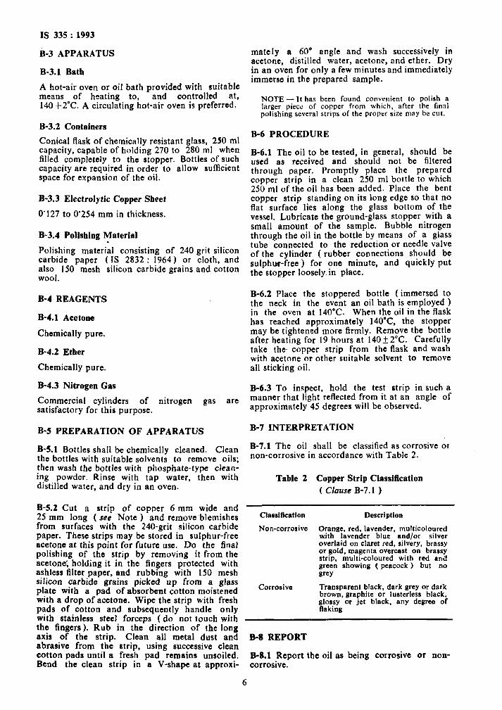
B-7.1 The oil shall be classified as corrosive or non-corrosive in accordance with Table 2.
Table 2 Copper Strip Classification
( Clause B-7.1 )
Classification Description
Non-corrosive Orange. red, lavender, multicoloured with lavender blue and/or silver overlaid on claret red, silvery, brassy or gold, magenta overcast on brassy strip, multi-coloured with red an& green showing ( peacock ) but no grey
Corrosive Transparent black, dark prey or dark brown, graphite or lusterless black, glossy or jet black, any degree of flaking
B-8 REPORT
B-8.1 Report the oil as being corrosive or non- corrosive.
6

IS 335 : 1993
ANNEX C [ Table 1, Item (xii) ]
DETERMINATION OF OXIDATION STABILITY
C-l GENERAL
C-l.1 The description of this method specifies the conditions for bringing about a series of successive physical and physic0 chemical reactions of a much more complex nature than measurement of a simple physical property, such as density, viscosity or even the fracture of a metal sample under tension.
C-1.1.1 It is, therefore, essential that such a test should be carried out under the supervision of an expert, both as regards the manner in which it is done and the interpretation of results.
C-l.2 While the test is relatively easy in the case of an already known oil, it may be much more difficult where a new product is concerned. It is known, for example, that certain unrefined oils now contain more sulphur than previously. It may therefore be feared, when examining an unknown oil whose, sulphurous constituents are liable to contaminate the metallic catalyst, that abnormal results will be obtained even if every care has been taken to utilize the correct appar- atus and to entrust the operations to experienced staff.
C-l.3 The conclusion to be drawn from the above is that special cases will have to be studied separately. The test has been primarily designed for the examination of pure refined petroleum distillates. Its extension to other products is an extrapolation.
C-2 PRINCIPLE
C-2.1 A stream of oxygen is bubbled, through the oil under test, which is maintained for a carefully measured period at a temperature of 1OO’C in the presence of metallic copper. The degree of oxidation is estimated by determining the amount of sludge and the neutralization value.
C-3 TEST VESSEL
C-3.1 The test vessel shall be a borosilicate or natural glass tube, provided with a B 24 cone, and having the following dimensions:
Overall length 210 f 2 mm
External diameter 26 + 0’5 mm
Wall thickness 1’4 f 0’2 mm
Height of the head 28f2mm
Oxygen inlet tube: a) External diameter 5’0 f 0’4 mm
b) Wall thickness 0’8 f 0’1 mm
C-3.2 The test tube is fitted with a Drechsel head to which is attached the inlet tube which extends to within 2-3 mm of the bottom and has its end ground at an angle of 60” to the horizontal axis ( see Fig. 1 ).
EXT do 5.0: O.L
’ 2.smf
All dimensions in millimetres.
FIG. 1 TEST VESSEL
C-4 QUANTITY OF OIL
C-4.1 The quantity of oil shall be 25fO’l g.
C-4.2 The oil, mixed by stirring, is first filtered through a sintered glass filter as described under C-11.1.3.
C-5 REAGENTS
C-5.1 Oxygen
Obtained from liquid air, minimum purity 99’4 percent.
C-S.2 Normal Heptane
Conforming to the following:
a) Density at 20°C : 0’683 80fO’OOO IS b) Refractive index at 20°C : 1‘387 70f
0’000 I5 c) Solidification temperature: -90’71”C, Min
d) Distillation: 50 percent recovered 98’427f 0’02S”C.
7
IS 335:1993
e) Differential : 80 percent recovered minus 20 percent recovered 0’02O”C, Max.
NOTE-This reagent is identical with n-heptane reference fuel used in testing the octane number of internal combustion engine fuel.
C-S.3 Indicator Solution
A solution of 2 g of alkali blue 6B in 100 ml of pure ethyl alcohol.
C-S.4 Tirntioa Solution
0’02 N alcoholic potassium hydroxide solution.
C-6 OXYGEN SUPPLY
C-6.1 The oxygen shall be thoroughly dried by passing it through concentrated sulphuric acid and over lime or soda lime, or by any other method of equal or greater efficacy.
C-6.2 A 10 litre flask, acting as a surge vessel, smoothes the oxygen flow, excess of which bubbles through mineral oil contained in a test tube.
The flow rate shall be 1 f 0’1 I/h.
NOTE - The method used to check the flow rate is left to the discretion of the testing authority.
f-7&Ri;HOD OF CLEANING THE TEST .
C-7.1 The test-tube shall be chemically cleaned. ’ A method of cleaning which has been found
satisfactory is to wash with acetone, distilled water, then with concentrated sulphuric acid which is removed by washing, first with tap water, then with distilled water.
C-7.2 The reagents used shall be of chemically pure grade.
C-7.3 The apparatus is dried in an air-oven at 105-I 10°C for at least 3 hours, and then allowed to cool to room temperature in a desiccator in which the test-tubes are kept until they are used.
C-g HEATING ARRANGEMENTS
C-g.1 The test tomperature for the oil shall be 100’0&0’5”C.
C-g.2 The temperature of the thermostatic block required to maintain the oil at IOO’C governs the temperature of the air above the oil surface. The temperature just below the cover of the test tube shall be not less than 7O’C.
C-8.3 A wrought aluminium block provided with holes to accommodate the test vessel, described in C-3, shall be used for heating. Provision should bei made in the block for at least four test-tubes ( tott vessels ) and its temperature maintained constant by the use of a contact thermometer. The
test-tubes should be inserted as far as possible into the holes. If they cannot be completely inserted, shaft metal collars passing through the insulating cover and surrounding each test-tube will ensure heating over the full length of the tube.
C-9 CATALYST
C-9.1 The metallic copper used as oxidation catalyrt consists of a wire of non-annealed com- mercial electrolytic copper of diameter between 1’00 and 1’02 mm. It is prepared as follows:
a) Immediately before use, the copper wire is polished with No. 00 emery cloth or an equivalent abrasive cloth ( see Note ). All traces of abrasive are removed with a lintless filter paper and then-with a dry, lintless cloth.
NOTE - The emery grains used in the manufacture of No. 00 abrasive cloth shall pass con-pletely through 67-mesh/cm sieve.
The mesh characteristics are defined by the following dimensions:
Aperture width 0’089 mm
Wire diameter 0’061 mm
b)
4
d)
A piece of the pclished wire 305 f I’0 mm long is rolled into a spiral of approximately 20 mm external diameter and 50 mm in length.
The spiral is thoroughly cleaned by dipping it into chemically pure ethyl ether, dried in air and immediately introduced into the test vessel.
To avoid contamination, the prepared copper shall be handled only with tweezers. The copper wire shall not be re-used.
C-10 DURATION OF TEST
C-10.1 The test-tube shall be introduced into the apparatus previously brought to operational temperature. The duration of the test shall be 164 hours, this being reckoned from the time when the oil reaches a temperature of 100°C and when the flow of oxygen has been adjusted to the prescribed rate of I litrelhour. The time taken to adjust the oxygen flow shall not exceed 10 minutes,
C-10.2 The measurements of sludge and neutra- lization value, after 48 and 96 hours, are carried out only when it is desired to plot an ageing curve.
C-11 DETERMINATIONS ON OXIDIZED OIL
C-l 1.1 Sludge Formation
C-11.1.1 The sludge shall be precipitated by adhering strictly to the procedure described below.
8

IS 335 : 1993
C-11.1.2 The sample of 25 g of artificially aged oil shall be cooled in the dark for 1 hour. and then poured into an Erlenmeyer flask of 500 ml capacity, fitted with a ground glass stopper. Use 300 ml of n-heptane to recover, by swrilling, the oil adhering to test-tube, coppet spiral and oxygen lead-in tube, n-heptane should then be added to the oil in the flask.
C-11.1.3 The mixture shall be allowed to stand in the dark for 24 hours, at a temperature of 27f2”C, before filtering through a glass filter previously dried to constant mass. The maximum diameter of the pores of the glass filter shall be between 5 and I5 microns, when determined in accordance with the method described in C-l 1.1.8.
C-11.1.4 At the start of filtering only a small pressure drop should be used to prevent the sludge passing through the filter. Cloudy filtrates should be passed through a second time
C-11.1.5 All traces of oil shall be carefully removed by repeated washing of the sludge with n-heptane. The total volume of the n-heptane used for the washing of the sludge shall be I50 ml. The filter cohtaining the sludge is dried at 110°C to constant weight.
C-11.1.6,.Sludge adhering to the catalyst, to the test-tube, and to the oxygen lead-in tube is transferred, by dissolvin chloroform ( a total o P
it in small quantities of 30 ml ). to a tared
porcelain vessel. It is then dried at 110°C after evaporation of the chloroform, to constant mass. The weight of the residue is added to that of the sludge obtained by precipitation with normal heptane.
C-11.1.7 The total sludge is expressed as a percentage of the initial mass of the oil.
NOTE - If n-heptane recovered from previous tests is used, it is important that its acidity be checked before reuse. A product which is not neutral shall be purified before use.
C-11.1.8 Determination of Maximum Diameter of Pores of a Glass Filter
It is not easy to determine the mean diameter of the pores of a glass filter. The determination of ttie maximum diameter of the pores provides a valuable indication of the capacity of the filter, that is the maximum diameter of spherical particle that may pass through it.
The maximum diameter of the pores is determin- ed by measuring the air pressure necessary to cause the first air bubble to pass through the filter moistened by the liquid to be tested.
The following relation is used:
D = 30 X 10” X r P
Where
D - diameter in microns of the pores,
r = surface tension of the test liquid in N/m, and
P = observed pressure in mm Hg.
In order to check a filter having a maximum pore diameter of 5 to 15 microns, either water or carbon tetrachioride is used as a test liquid.
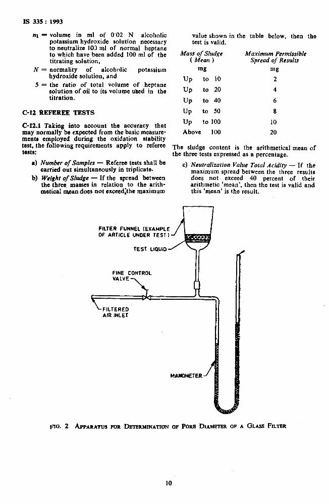
The glass filter is completely immersed in the test liquid of which a film of several millimetres thickness will remain on the upper surface of the filter attached to the apparatus ( see Fig. 2 ).
A uniformly increasing pressure is applied to the filter until one or two bubbles ot air appear in the liquid above the filter. The manometer reading enables the maximum diameter of the pores to be calculated. This manometer may be directly calibrated in pore diameters.
For a filter whose maximum pore diameter is between 5 and I5 microns, the manometer reading in mm Hg will be 435 to 145 for water and 160 to 55 for carbon tctrachloride.
C-l 1.2 Neutralization Value
C-11.2.1 The heptane solution obtained after filtering off the sludge is collected in a 500 ml measuring flask and made up to the mark with normal heptane. Three determinations of the neutralization value are made on 100 ml samples of the heptane-oil solution.
C-11.2.2 Immediately before use. the titrating solution is prepared as follows:
a)
b)
4
Add I to 3 ml of the alkali solution and a drop of 0’1 N HCL to sensitize the indi- cator to 100 ml of a mixture of 3 parts of benzene to 2 parts of ethyl alcohol by volume.
Neutralize the mixture by 0’02 N potassium hydroxide to give a red colour comparable to that of a 10 percent solution of cobalt nitrate [ CO ( NOJ )a 6HsO 1. This colour shall persist for at least 15 seconds.
Add the same volume of neutralized solvent to 100 ml of the heptane solution while stirring.
This solution is then titrated with 0’02 N alcoholic potassium hydroxide at a temperature not exceeding 25’C.
C-11.2.3 The neutralization value shall be calcu- lated according to the following formula:
( ns - nl ) 56’lN Neutralization value - .- 5
where
ns = volume in ml of 0’02 N alcoholic potassium hodroxide solution necessary to neutralize the normal heptane oil solution,
9
IS 335 : 1993
nl - volume in ml of 0’02 N alcoholic potassium hydroxide solution necessary to neutralize 103 ml of normal heptane to which have been added 100 ml of the titrating solution,
N = normality of alcoholic potassium hydroxide solution, and
5 = the ratio of total volume of heptane solution of oil to its volume t&cd in the titration.
value shown in the table below, then the test is valid.
Mass of Sludge Maximum Permissible ( Mean ) Spread of Results
mg mg
UP to 10 2
UP to 20 4
UP to 40 6
C-12 REFEREE TESTS UP to 50 8
C-12.1 Taking into account the accuracy that may normally be expected from the basic measure- ments employed during the oxidation stability test, the following requirements apply to referee tests:
a) Number of Samples - Referee tests shall be carried out simultaneously in triplicate.
b) W’e~ghr of Sludge - If the spread between the threq masses in relation to the arith- metical mtan does not exceedithe maximum
UP to 100 10
Above 100 20
The sludge content is the arithmetical mean of the three tests expressed as a percentage.
c) Neutralization Value Total Acidity - If the maximum spread between the three results does not exceed 40 percent of their arithmetic ‘mean’, then the test is valid and this ‘mean’ is the result,
FILTER FUNNEL (EXAMPLE OF ARTICLE UNDER TEST 1
TEST LlQUlD
FINE CONTROL
F~O. 2 APMRITUS FOR DBTERMINATIUN OF PORE DIAMETER OF A GLASS FILTER
10
IS 335 : 1993
ANNEX D [ Table 1, hem (xvi) ]
METHOD OF DETERMINATION OF SK VALUE
D-l GENERAL
D-l.1 The behaviour of insulating oils in the presence of concentrated sulphuric acid furnishes information on the refining degree of mineral oil.
D-2 APPARATUS
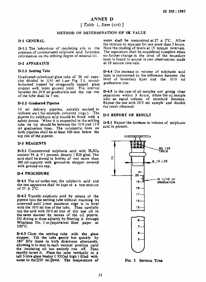
D-2.1 Settling Tube
Graduated cylindrical glass tube of 20 ml capa- city divided in l/IO ml (see Fig. 3 ), round- bottomed topped by octagonally capped glass stopper with taper ground joint. The interval between the 20’0 ml graduation and the top rim of the tube shall be 7 cm.
D-2.2 Graduated Pipettes
10 ml delivery pipettes, suitably marked to indicate use ( for example, colourcd rings ). The pipette for sulphuric acid should be fitted with a safety device. When it is suspended in the settling tube its tip should be between the 10’0 and 11’0 ml graduation lines. The volumetric lines on both pipettes shall be at least 100 mm below the top rim of the pipette.
D-3 REAGENTS
D-3.1 Concentrated sulphuric acid with HpSOd content 96 f 0’1 percent, density 1’828 g/ml. The acid shall be stored in bottles of not more than 300 ml capacity with ground-in stopper covered with ground-on cap.
D-4 PROCEDURE
D-4.1 The oil under test, the sulphuric acid and the test apparatus shall be kept at a tem?crature of 27 ct 2°C.
D-4.2 Transfer sulphuric acid by means of the pipette into the settling tube without touching its innerwall until lower maniscus edge is in level with the 10’0 ml line of the tube. Then carefully top the acid with 10’0 ml line of dry teat oil in the same manner by means of the oil pipette. Oil drying is done suitably by filtering it through Whatman No. 1 orl]equivalent filter paper at 100°C.
D-4.3 Close the settling tube with the glass stopper. Tilt the tube gently but quickly by 180’ fifty times in both directions alternately, allowing it to stay ia each vertical position until the insulating oil has entirely run off. Then rapidly iovart it. Place the tube vertically in a tall Slitto glass beaker ( 330:ml high ) filled with wator to the]250 ml ;~lovel. The temperature of
11
water shall be maintained at 27 f 2°C. Allow the mixture to separate for not more than 3 hours. Note the reading of levels at 15 minute intervals. The separation shall be considered complete when no further change in the level of the boundary layer is found to accrue in two observations made at 15 minute intervals.
D-4.4 The increase in volume of sulphuric acid layer is represented by the difference between the level of boundary lzyer and the 10’0 ml graduation line.
D-4.5 In the case of oil samples not giving clear separation wrthin 3 hours, dilute the oil sample with an equal volume of standard benzene. Repeat the test with 10’0 ml sample and double the result obtained.
D-5 REPORT OF RESULT
D-5.1 Report the increase in volume of sulphuric acid in percent.
B-
7
6 0 5
Fro. 3 Sm-rr~~ TUBE
Bureau of Indian Standards
BIS is a statutory institution established under the Bureau of Indim Standards Act, 1986 to promote harmonious development of the activities of standardization, marking and quality certification of goods and
attending to connected matters in the country.
Copyright
BIS has the copyright of all its publications. No part of these publications may be reproduced in any form without the prior permission in writing of BIS. This does not preclude the free use, in the course of
implementing the standard, of necessary details, such as symbols and sizes, type or grade designations. Enquiries relating to copyright be addressed to the Director (Publication), BIS.
Review of Indian Standards
Amendments are issued to standards as the need arises on the basis of comments. Standards are also reviewed periodically; a standard along with amendments is reaffirmed when such review indicates that no changes are needed; if the review indicates that changes are needed, it is taken up for revision. Users of Indian Standards should ascertain that they are in possession of the latest amendments or edition by referring to the latest issue of ‘BIS Handbook’ and ‘Standards Monthly Additions’.
This Indian Standard has been developed from Dot: No. ETD 3 ( 3321 )
Amend No.
Amendments Issued Since Publication
Date of Issue Text Affected
Headquarters: BUREAU OF INDIAN STANDARDS
Manak Bhavan, 9 Bahadur Shah Zafar Marg, New Delhi 110002 Telegrams: Manaksanstha Telephones: 323 0131,323 33 75,323 94 02 (Common to all offices)
Regional Offices: Telephone
Central : Manak Bhavan, 9 Bahadur Shah Zafar Marg NEW DELHI 110002
Eastern :
Northern :
l/14 C.I.T. Scheme VII M, V.I.P. Road, Maniktola CALCUTTA 700054
SC0 335336, Sector 34-A CHANDIGARH 160022
Southern : C.I.T. Campus, IV Cross Road, C!IENNAI 600113
Western :
Branches :
Manakalaya, E9 MIDC, Marol, Andheri (East) MUMBAI 400093
AHMADABAD. BANGALORE. BHGPAL. BHUBANESHWAR. COIMBATORE. FARIDABAD. GHAZIABAD. GUWAHATI. HYDERABAD. JAIPUR. KANPUR. LUCKNOW. NAGPUR. PATNA. PUNE. THIRUVANANTHAPURAM.
323 76 17,323 38 41
{ 337 84 99,337 85 61 337 86 26,337 9120
{ 60 38 43 60 20 25
{ 235 02 16,235 04 42 235 15 19,235 23 15
1 832 92 95,832 78 58 832 78 91,832 78 92
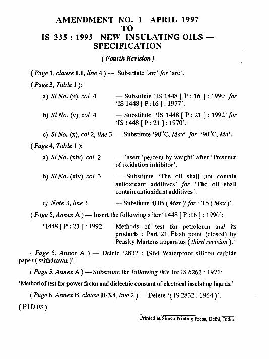
AMENDMENT NO. 1 APRIL 1997 TO
IS 335 : 1993 NEW INSULATING OILS - SPECIFICATION
(Fourth Revision)
(Page 1, clause 1.1, Ihe 4 ) - Substitute ‘arc’ for ‘are’.
( Page 3, Table 1):
a) SZNo. (ii), co1 4 - Substitute ‘IS 1448 [ P : 16 ] : 1990’ for ‘IS 1448 [ P :16 ] : 1977’.
b) SZ No. (v), col 4 - Substitute ‘IS 1448 [ P : 21 ] : 1992’for ‘IS 1448 [ P : 211: 1970’.
c) Sl No. (x), co1 2, line 3 -Substitute ‘90°C, Max’ for ‘90°C, Ma’.
(Page 4, Table 1):
a) SZ No. (xiv), col 2 - Insert ‘percent by weight’ after ‘Presence of oxidation inhibitor’.
b) SZ No. (xiv), col 3 - Substitute ‘The oil shall not contain antioxidant additives’ for ‘The oil shall contain antioxidant additives’.
c) Note 3, line 3 - Substitute ‘0.05 (MUX )’ for ‘ 0.5 ( MUX )‘.
( Page 5, Annex A ) - Insert the following after ‘1448 [ P :16 ] : 1990’:
‘1448 [ P : 211: 1992 Methods of test for petroleum and its products : Part 21 Flash point (closed) by Pensky Martens apparatus ( fhird revision ).’
( Page 5, Annex A ) - Delete ‘2832 : 1964 Waterproof silicon carbide paper ( withdrawn )‘.
(Page 5, Annex A ) -Substitute the following title for IS 6262 : 1971:
‘Method of test for power factor and dielectric constant of electrical insulating liquids.’
( Page 6, Annex B, clnrtse B-3.4, Iine 2 ) - Delete ‘( IS 2832 : 1964 )‘.
(ETD03)
Printed at S~IIICO printing Press, D&i, ht.&a
