is 13848 (1993): inland vessels - rubber fenders - law.gov
TRANSCRIPT

Disclosure to Promote the Right To Information
Whereas the Parliament of India has set out to provide a practical regime of right to information for citizens to secure access to information under the control of public authorities, in order to promote transparency and accountability in the working of every public authority, and whereas the attached publication of the Bureau of Indian Standards is of particular interest to the public, particularly disadvantaged communities and those engaged in the pursuit of education and knowledge, the attached public safety standard is made available to promote the timely dissemination of this information in an accurate manner to the public.
इंटरनेट मानक
“!ान $ एक न' भारत का +नम-ण”Satyanarayan Gangaram Pitroda
“Invent a New India Using Knowledge”
“प0रा1 को छोड न' 5 तरफ”Jawaharlal Nehru
“Step Out From the Old to the New”
“जान1 का अ+धकार, जी1 का अ+धकार”Mazdoor Kisan Shakti Sangathan
“The Right to Information, The Right to Live”
“!ान एक ऐसा खजाना > जो कभी च0राया नहB जा सकता है”Bhartṛhari—Nītiśatakam
“Knowledge is such a treasure which cannot be stolen”
“Invent a New India Using Knowledge”
है”ह”ह
IS 13848 (1993): Inland vessels - Rubber Fenders [TED 18:Inland, Harbour Crafts and Fishing Vessels]


IS 13848 : i993
Indian Standard
INLAND VESSELS - RUBBER FENDERS - SPECIFICATION
UDC 629’122’015’65 [ 678’4 ]
Q BIS 1993
BUREAU OF INDIAN STANDARDS MANAK BHAVAN, 9 BAHADUR SHAH ZAFAR MARG
NEW DELHI 110002
November 1993 Price Group 7
Inland and Harbour Craft Sectional Committee, TED 18 .
FOREWORD
This Indian Standard was adopted by the Bureau of Indian Standards, after the draft finalized :by the Inland and Harbour Craft Sectional Committee had been approved by the Transport Engineering Division Council.
Rubber fenders have gained great importance as they afford a softer contact, compared with fenders of other materials, between:
a) Ships and berthing structures during berthing operations and subsequent~stay at berths.
b) Structures and passing vessels culminating in collision.
c) Ships and tugs-in-attendance during, for example, berthing and unberthing operations.
Berthing structures include dock-walls, locks and dry-docks, dolphins, jetties, quays and wharves, offshore moorings, terminals and platforms. Examples of structures liable to impact from passing vessels are bridge piers, buoys and offshore platforms.
a) The increasing lightness of construction of both ships and structures.
b) The increasing cost of repair of impact damage to both shtps and structure’s
c) Susceptibility of cargo to damage and loss and, in some cases, degradation of environment.
d) Cost of idling of ships and structures whilst repairs are awaited or are in progress.
e) The need to upgrade a berthing facility so as to enable it to accept larger vessels than initially contemplated.
Accidental destruction of bridges by, and damage to or sinking of, passing vessels may cause great disruption of communication and transportation on land and creation of wrecks and obstruction navigation in waters. Specialised vessels such as Liquefied Petroleum Gas ( LPG ) Carriers, Liquefied Natural Gas ( LNG ) Carriers and container ships are more vulnerable than other types of ships and may sustain internal damage on account of harsh contact with berthing structures.
Vessels which carry inflammable or explosive cargo have to make spark-free contact with berthing structures and vessels in order to reduce fire and explosion hazards.
IS 4651 ( Part 3 ) : 1974 deals with the determination of ‘berthing load’, the force with which a ship engages a berthing structure during berthing.
IS 465~1 ( Part 4 ) : 1979 describes in relation to berthing structures:
-Function of fenders ( 10.1 )
- Varieties of fenders in use ( 10.2 )
-Fender system design ( 10.3)
Provision of rubber fenders in harbour tugs has been stipulated in 3.10.1.1 of IS 8950 : 1993 ‘Inland vessels - Harbour tugs - General requirements (first revision )‘.
While preparing this standard considerable assistance has been derived from the information supplied on the subject by M/s P.V. Kuruvilla, Calcutta. Assistance has also been derived from ASTM No. D 2240 issued by the American Society for Testing and Materials for stipulating the ‘Standard method for rubber Durometer hardness’.
The committee responsible for the preparation of this standard is given in Annex B.
For the purpose of deciding whether a particular requirement of this standard is complied with the final value, observed or calculated, expressing the result of a test or analysis, shall be rounded off in accordance with IS 2 : 1960 ‘Rules for rounding off numerical values ( revised )‘. The number of significant places retained in the rounded off value should be the same as that of the specified value in this standard.

*
IS 13848 : 1993
Indian Standard
INLAND VESSELS -RUBBER FENDERS- SPECIFICATION
The followine Indian Standards are necessary adjuncts to this Stan&d:
IS No.
3400 (Part 1) : 1987
Title
Methods of test for vulcanized rubbers : Part 1 Tensile stress-strain properties ( second revision )
3400 (Part 2) : 1971
Methods of test for vulcanized rubbers : Part 2 Hardness ( first revision )
3400 (Part 3) : 1987
Methods of test for vulcanized rubbers : Part 3 Abrasion resistance using a rotating cylindrical drum device (first revision )
3400 (Part 4) : 1987
Methods of test for vulcanized rubbers : Part 4 Accelerated ageing ( second revision )
3400 (Part 6) : 1983
Methods of test for vulcanized rubbers : Part6 Resistance to liquids (first revision )
3400 (Part 10) : 1977
3400 (Part 20) : 1977
4651 (Part 3) : 1974
Methods of test for vulcanized rubbers : Part 10 Compression set at constant strain (first revision )
Methods of test for vulcanized rubbers : Part 20 Resistance to ozone
Code of practice for planning and design of ports and harbours : Part 3 Loading (first revision )
3 TYPES
3.1 General
1 SCOPE
1.1 This standard lays down the requirements for rubber fenders.
1.2 This standard does not deal with pneumatic and foam-filled fenders.
2 REFERENCES
3.1.1 Fenders absorb the energy of impact from a vessel and, in doing so, transmit to the structure they protect a force. which the structure can safely bear. The force thus engendered may affect the vessels hull also and fenders shall be so selected that the force exerted will not cause damage to the hull [ see 6.2.2 of IS 4651 (Part 3) : 19741. Most fendering materials rely, for the discharge of their function, on their being rendered into springs. After a vessel is arrested a fender will release all the energy absorbed during the impact and it will almost immediately revert to the same or almost the same physical condition existing
before impact. Of all fendering materials rubber has the greatest test capability to deform on application of force and hence its remarkable capacity for storing energy. A given weight of rubber is capable of absorbing 150 times -as much energy as may be absorbed by tempered steel of the same weight.
3.1.2 Types of rubber fenders in use are many. Fender&g selected shall be compatible with the structure it is called to protect as well as with the hull of vessels which use the structure as a berth. Rubber, springs employed as fenders act in bending, compression or shear, any one form of strain being predominant in the presence of the other two forms. The energy stroed in a fender is equal to the work done in deforming it. The energy is derived from the force- deformation or load (reaction) - displacement (deflection) relationship obtained by testing a length of fendering, or a whole fender, in a suitable machine. A load-deflection curve is drawn from the test results. The energy stored up to a given measure of displacement X is the area under the load-deflection curve from origin to the point X (see Fig. 1 and 2).
0 DEFORMATION X
FIG. 1 TYPICAL FORCE AND DEFORMATION CHARACTERISTIC CUKVE
0 X DEFORMATION
FIG. 2 TYPICAL ENERGY AND DEFORMATION CHARACERIS~C CurwE
1

IS 13848 : 1993
3.2 Bending Action Fenders
An analogy may be drawn between the load-deflection characteristic of a leaf spring whose ends are free to move and of a bending action type of rubber spring ( see Fig. 3 ) Whose ends are also free to move. As the load is applied and increased the elements give and the free ends take up ever new positions until the elements are flattened and no further bending is possible.
LEAF SPRING
3.2.1 The Hollow Cylindrical Fender
A fender of this, very commonly used, type, may be considered as consisting of two identical leaf springs placed one above the other in the manner of Fig. 4. The spring element has constant thickness and width and both the ends are free to move (In use this type of fender is freely supported by chains, wire rope or rods passing through the bore. Almost always the diameter of the bore is half the outside diameter, D).
1 \\\\\\\\\\\\’
RUBBER SPRING
FIG. 3 BENDING ACTION
FIG. 4 HOLLOW CYLINDRICAL FENDERS
2
IS 13848 : 1993
3.2.2 The Rectungrdar Section ( Including Square Section ) Fender
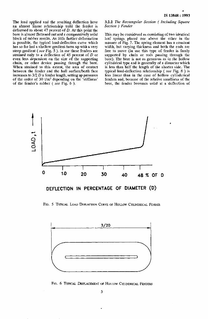
The load applied and the resulting deflection have an almost linear relationship until the fender is deformed to about 47 percent of D. At this point the bore is almost flattened out and a comparatively solid block of rubber results. As little further deformation is possible, the typical load-deflection curve which has so far had a shallow gradient turns up with a very steep gradient ( see Fig. 5 ). In use these fenders are strained only to a deflection of 45 percent of D or even less dependent on the size of the supporting chain, or other device passing through the bore. When strained to this extent, the area of contact between the fender and the hull surface/berth face increases to 3/2 D x fender length, setting up pressures of the order of 30 t/m2 depending on the ‘stiffness’ of the fender’s rubber ( see Fig. 6 ).
This may be considered as consisting of two identical leaf springs placed one above the other in the manner of Fig. 7. The spring element has a constant width, but varying thickness and both the ends are free to move (In use this type of fender is freely supported by chain or -rods passing through the bore). The bore is not as generous as in the hollow cylindrical type and is generally of a dimaeter which is less than half the length of the shorter side. The typical load-deflection relationship ( see Fig. 8 ) is less linear than in the case of hollow cylinderical fenders and, because of the relative smallness of the bore, the fender becomes solid at a deflection of
0 10 20 30 40 48% OF D
DE-FLECTION IN PERCENTAGE -OF DIAMETER (D)
FIG. 5 TYPICAL LOAD DEFLECIION CURVE OF HOLLOW CYLINDRICAL FENDER
FIG. 6 TYPICAL DISPLACEMENT OF HOLLOW CYLINDRICAL FENDERS
3

IS 13848 : 1993
about 35 percent of the height H. Also, as the contact area does not increase much more than in the initial (inloaded) condition face pressures of the order of 50 t/m* may be set up.
3.2.3 The D Fender
This may be considered as a single leaf spring with ends neither wholly free nor entirely restrained ( see
(4
0 04
FIG. 7 HOLLOW RECTANGULAR FENDERS
.
Fig. 9 ). As in rectangular section type, the bores are less generous than in the hollow cylindrical type. The bore may be round or of the shape or a crescent. The typical load-deflection curve has little linearity but a high gradient which becomes steep as the bore closes at a deflection about 25 percent of the height H ( see Fig. 10 ). Face pressures set up are high, of the horder of 80 t/m*.
0 10 20 30% OF H
DEFLECTION IN PERCENTAGE OF HEIGHT (H)
FIG. 8 TYPICAL LOAD DE&ECTION CURVE FOR RECMNGULM FENDER
(4 (b) ROUND HOLE ‘d ~FENDER
HOLE FOR SECURING
(4
CRESCENT HOLE
FIG.
I I I I
0 10 20 30 % OF H
DEFLECTION IN PERCENTAGE
OF HEIGHT (H)
10 TYPICAL J_OAD DEFLECTION CURVE ‘D’ FENDER
FOR
FIG. 9 ‘D’ FENDERS ‘0’ FENDER
3.3 Compression Action Buckling Fender
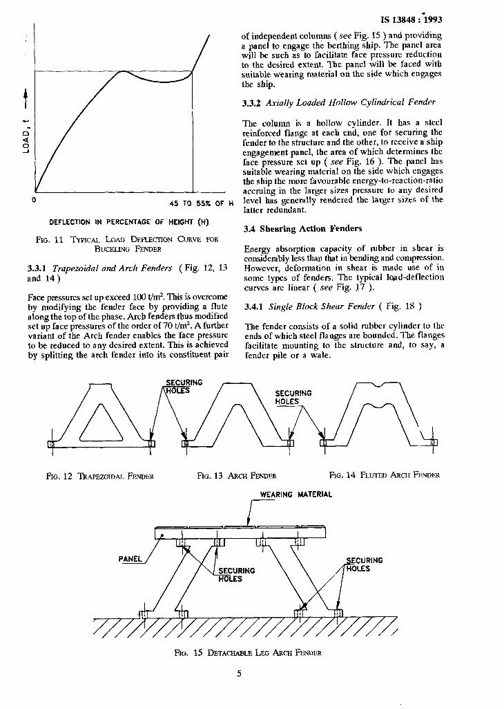
These consist of end-loaded rubber columns or struts. As loading in compression begins and progresses the columns swell and become shortened until a critical load is reached when the columns collapse. As loading continues the columns become contorted until they become solid. The typical load- deflection curve has ~a high gradient in the ‘Compression’ phase and a small negative gradient in the buckling phase and a very steep gradient in the solid phase (see Fig. 11 ). Almost twice as much energy is absorbed during the buckling phase as in the compression phase.
4
0 45 TO 55% OF H
DEFLECTION IN PERCENTAGE OF HEIGHT (H)
FIG. 11 TYPICAL LOAD DEFLECTION CURVE FOR BUCKLING FENDER
3.3.1 Trapezoidal and Arch Fenders ( Fig. 12, 13 and 14)
Face pressures set up exceed 100 t/m2. This is overcome by modifying the fender face by providing a flute along the top of the phase. Arch fenders thus modified set up face pressures of the order of 70 t/m2. A further variant of the Arch fender enables the face pressure to be reduced to any desired extent. This is achieved by splitting the arch fender into its constituent pair
IS 13848 :i993
of independent columns ( see Fig. 15 ) and providing a panel to engage the berthing ship. The panel area will be such as to facilitate face pressure reduction to the desired extent. The panel will be faced with suitable wearing material on the side which engages the ship.
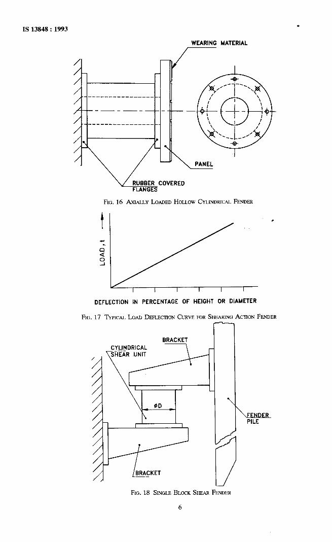
3.3.2 Axially Loaded Hollow Cylindrical Fender
The column is a hollow cylinder. It has a steel reinforced flange at each end, one for securing the fender to the structure and the other, to receive a~ship engagement panel, the area of which determines the face pressure set up ( see Fig. 16 ). The panel has suitable wearing material on the side which engages the ship the morefavourable energy-to-reaction-ratio accruing in the larger sizes pressure to any desired level has generally rendered the larger sizes of the latter redundant.
3.4 Shearing Action Fenders
Energy absorption capacity of rubber in shear is considerably less than that in bending and compression. However, deformation in shear is made use of in some types of fenders. The typical load-deflection curves are linear ( see Fig. I7 ).
3.4.1 Single Block Shear Fender ( Fig. 18 )
The fender consists of a solid rubber cylinder to the ends of which steel flanges are bounded. The flanges facilitate mounting to the structure and, to say, a fender pile or a wale.
FIG. 12 TUPEZ~IDAL FENDER FIG. 13 ARCH FENDER FIG. 14 FLUTED ARCH FENDER
WEARING MATERIAL
FIG. 15 DETACHABLE LEG ARCH FENDER
IS 13848 : 1993 .
WEARING MATERIAL
/ -
-_ __----_____---__ __
-------
~~------~----___-- __
/ ‘1 \
FLANGES
FIG. 16 AXIALLY LOADED HOLLOW CYLINDRICAL FENDER
DEFLECTION IN PERCENTAGE OF HEIGHT OR DIAMETER
FIG. 17 TYPICAL LOAD DEFLECTION CURVE FOR SKEAFUNG ACTION FENDER
BRACKET CYLINDRICAL
\SHEAR UNIT \ -I-l--I
FIG. 18 SINGLE BLOCK SHEAR FENDER
6

WEARING
FIG. 19 MUJXIBLCICK SHEAR FENDER
3.4.2 Multi-Block Shear Fender ( Fig. 19 )
The rubber is rectangular and in thinner block and are sandwiched between plates or steel which are bonded to the rubber blocks. A panel for engagement of ship is a necessity. This arrangement facilitates larger deflectionof fender and hence larger energy absorption capacity than in the case of the single block fender.
FIG. 20 TUBULAR SHEAR FENDER
3.4.3 Tubular Shear Fender ( Fig. 20 )
A hollow rubber column, having steel pipes bonded to it externally and internally, is deformed in shear
IS 13848 : i993
with consequent storage of energy. This is used where a fendering arrangement has to be both compact and to present as little area as possible to waves, for example, in off-shore structures.
4 PERFORMANCE REQUIREMENTS
The performance requirements of fenders shall be as given in Table 1.
5 MATERIAL AND MANUFACTURE
5.1 Material
Natural rubber and synthetic rubber such as EPDM are most commonly used in rubber fender manufacture. The manufacturing process, begins with ‘mixing’ or ‘compounding’ of rubber with other materials to achieve:
a) re-enforcement (with carbon black),
b) vulcanizing (with agents such as Sulphur), and
c) protection against degradation (with agents such as anti-oxidants and antifozonants).
.
5.2 Manufacturing Methods
Fabrication of fenders in accomplished by compression moulding (with simultaneous vulcanization) or by extrusion (with vulcanization after fabrication). Soundness of the product depends primarily on the quality of the compounded rubber. All types of fenders may be manufactured by compression moulding. Manufacture by extrusion is limited by size and confined to certain types.
6 TESTS
6.1 Tests on Rubber
Three types of tests are carried out:
a) for control of process quality,
b) to predict behaviour on being exposed to environment, and
c) to predict behaviour on being exposed to hazards specific to service.
6.2 Quality Control Tests ( see 6.5 Group I )
Tests are carried out on thin ( 3 mm thick ) flat specimens called dumbells. These specimens are fabricated and cured in small moulds and unless the specimens pass the following tests, the rubber compounds ( for which the specimen are made ) are not to be used:
a)
b)
C)
hardness with shore A durometer,
tensile strength, and
percentage elongation at break.
7

IS 13848 : 1993
Action
1. Bending
Table 1 Performance Requirements of Fenders
( ClulJse 4 )
Type Maximum Size Corresponding to Face Pressure
( See Note 1 ) Maximum Size - Y
Energy Reaction
1. Hollow cylindrical 1 000 mm OD 11 tm/m 45 t/m 30 t/m2
2. Rectangular 305 x 305 mm 3 tm/m 60 t/m 50 t/m2
(sides)
3. D 305 mm H 2 tm/m 70 t/m 80 t/m2
2. Compression 1. Trapezoidal 1500 mm H 60 tm/m 120 t/m 110 t/m*
with buckling
2. Arch 1 500 mm H 6.5 tm/m 125 t/m 110 t/m2
3. Fluted arch 1 500 mm H 68 tm/m 130 t/m 75 t/m’
4. Detachable leg arch 1 500 mm H 65 tm/m 125 t/m Reduceable to
5. Axially loaded hollow 2 500 mm H 250 tm for 300 t for desired level cylinder unit unit
3. Shear 1. Single block 210 mm 3 tm for 30 t for 30 t/m2
unit unit
3 _. Multi-block 1 600 mm 50 t/m for 100 t fo: Reduceable to
unit unit desired level
3. Shear tube - - - -
NOTES 1 Higher sizes may be manufactured. However, in energy limits above those shown axially loaded hollow cylindrical fenders are preferred because of their higher energy-to-reaction-ratio.
2 When the weight of the frontal frame exceeds a certain limit and when the longitudinal force is excessive, use of shear chains shall be mandatory.
6.3 Tests Relating to Behaviour in Environment ( see 6.5 Group II )
Rubber may be degraded in the following ways as a result of exposure to enviromnent in which fenders functions:
a)
b)
c>
d)
attack by oxygen is possible at normal ground temperature and on being heated by the sun. Anti-oxidants are incorporated in fender rubbers;
action of ultra-violet radiation as a result of exposure to sunlight. This is countered by the presence of carbon black;
combined action of atmospheric ozone, oxygen and sunlight causes surface cracks especially where the rubber is subjected to tensile deformation. Fender rubbers incorpo- rate chemical anti-ozonants and care is taken in fender installation to avoid tensile defor- mation; and
action of oily water found in ship berths causing rubber to smell. Fenders are normally not continuously immersed in water and, in any
case, their large bulk is a safeguard against adverse effects of immersion for short dura- tions.
6.4 Tests Relating to Service Hazards ( see 6.5 Group III )
As ship-motion is arrested and energy is absorbed by a fender the ship’s hull rubs against the fender and exerts a force parallel to the berth. This force will be many times the berthings load. The friction coefficient of the rubber (or the facing material on ship engagement panels) will determine the force that will be exerted on the components that secure the fender to the structure (coefficient of friction of dry rubber may be as high as 0.5 and if the rubber is lubricated, for example, with water, it may be almost negligible in comparison).
This lateral force will also determine the tendency of the rubber (or other facing material) to be torn off.
The movement of the hull over the rubber (or other facing material) will also cause abrasion.
8

.
IS 13848 : 1993
6.5 List of Tests on Fender-Rubber
Group
I
II
Tests for Test Method Remarks
1. Hardness (Shore A) -Annex A As appropriate to fender type
2. Tensile strength IS 3400 (Part 1) : 1987
3. Elongation at break IS 3400 (Part 1) : 1987
4. Heat resistance IS 3400 (Part 4): 1987
a) Change in tensile IS 3400 (Part 4) : 1987 strength
b) Change in elongation IS 3400 (Part 4) : 1987 at break
c) Change in hardness IS 3400 (Part 4) : 1987
d) Compression set IS 3400 (Part 10) : 1977
5. Ozone resistance IS 3400 (Part 20) : 1977
6. Water resistance IS 3400 (Part 6) : 1983
7. Oil resistance IS 3400 (Part 6) : 1983 a) Heavy oil * b) Light oil
III 8. Tear resistance IS 3400 (Part 2) : 1971
9. Abrasion loss IS 3400 (Part 3) : 1987
ANNEX A
( Clause 6.5 )
STANDARD TEST METHOD FOR RUBBER PROPERTY - DUROMET-ER HARDNESS
A-l SCOPE A-2 SIJMMARY OF TEST METHODS
A-l.1 This test method covers type a durometers, and the procedure for determining the indentation hardness of soft homogeneous vulcanized rubber materials.
A-2.1 The Type A durometer is used for measuring softer materials. This test method permits hardness measurements based on either initial indentation or indentation after specified periods of time, or both.
A-l.2 This test method is not applicable to the testing coated fabrics.
A-3 SIGNIFICANCE AND USE
A-l.3 The values stated in SI units are to be regarded as the standard.
A-l.4 This standard may involve hazardous materials, operations, and equipment. This method does not purport to address all of the safety problem+ associated with its use. It is the responsibility of whoever uses this method to consult and establish appropriate safety and health practices and determine the applicability of regulatory limitations prior to use.
A-3.1 This test method is based on the penetration of a specified indentor forced into the material under specified conditions. The indentation hardness is inversely related to the penetration and is dependent on the elastic modulus and viscoelastic behaviour of the material. The shape of the indentor and the force applied to it influence the results obtained so that there may be no simple relationship between the results obtained with one type of durometer and those obtained with either another type of durometer or another instrument for measuring hardness. This test method is an empirical test intended primarily for
9

IS 13848 : 1993
control purposes. No simple relationship existi between indentation hardness determined by this test method and any fundamental property of the material tested.
A-4 APPARATUS
A-4.1 Hardness-measuring apparatus or durometer consisting of the following components.
A-4.1.1 Presser foot with a hole having a diameter between 2.5 and 3.2 mm centered at least 6 mm from any edge of the foot.
A-4.1.2 Indentor formed from hardened steel rod with a diameter between 1.15 and 1.40 mm to the shape and _dimensions shown in Fig. 21.
A-4.1.3 Indicating device on which the amount of extension of the point of indentor may be read in terms of graduations ranging from zero for full extension of 2.46 to 2.54 mm to 100 for zero extension obtained by placing presser foot and indentor in firm contact with a flat piece of glass (see Note).
NOTE - Type A shore durometers serial numbers 1 through 16 300 and 16 351 through 16 900 and Type A-2 Shore Durometers numbers 1 through 8 077 do not meet the require- ment of 2.46 to 2.54 mm extension of the indentor at zero reading. These durometers will give readings which are low by amounts ranging from three units at 30 hardness to one unit at 90 hardness.
A-4.1.4 Calibrated spring for applying force to the indentor in accordance with one of the following equations:
Force, N = 0.550 + 0.075 H, (1)
where HA is the hardness reading on a Type A durometer.
A-5 TEST SPECIMEN
A-5.1 The test specimen shall be at least 6 mm in thickness unless it is known that identical results are obtained with a thinner specimen ( see Note ). A specimen may be composed of plied pieces to obtained the necessary thickness, but determinations made on such specimens may not agree with those made on solid specimens because the surfaces between plies may not be in complete contact. The lateral dimensions
.
of the specimen shall be sufficient to permit measurement at least 12 mm from any edge unless it is known that identical results are obtained when measurements are made at a lesser distance from an edge. The surface of the specimen shall be flat over sufficient area to permit the presser foot to contact the specimen over an area having a radius of at least 6 mm from the indentor point. A suitable hardness determination cannot be made on a rounded, uneven, or rough surface.
NOTE - The minimum requirement for the thickness of the specimen is dependent on the extent of penetration of the indentor into the specimen; that is, thinner specimens may be used for materials having hardness values at the upper end of the scale. The minimum distance from the edge at which measurements may be made likewise decreases as the hardness increases.
A-6 CALIBRATION
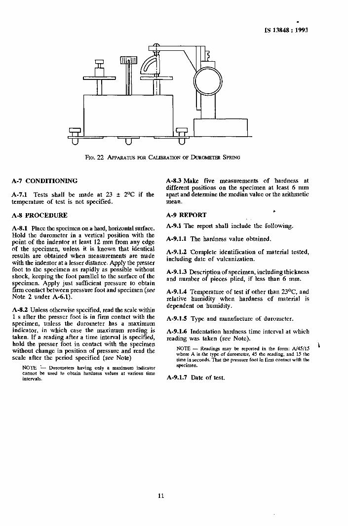
A-6.1 The spring may be calibrated ( see Note 1 ) by supporting the durometer in a vertical position and resting the point of the indentor on a small spacer at the center of one pan of a balance as shown in Fig. 22 in order to prevent interference beween presser foot and pan (seeNote 2). The spacer shall have a small cylindrical stem approximately 2.5 mm in height and 1.25 mm in diameter, and shall be slightly cupped on top to accommodate the indentor point. Balance the mass of the spacer by a tare on the opposite pan to balance the force on the indentor at various scale readings. The measured force (9.8 x mass in kilograms) shall equal the force calculated by Equation (1) within 2 0.08 N.
NOTJ?.S
1 Instruments specifically designed for calibration of duro- meters may be used.
2 Better reproducibility may be obtained by using either a durometer stand or a mass centered on the axis of the indentor or both.
A-6.2 Frequent checks in between calibrations in accordance with A-6.1, of the indentor by means of a test block supplied by the manufacturer shall be made to monitor the condition of the indentor relative to possible wear or damage.
Z.&O.04 LLI
All dimensions in millimetres.
FIG. 21 INDENTOR FOR TYPE A DUROMETER
10
.
IS 13848 : 1993
FIG. 22 A~PAFWTJS FOR CALIBRATION OF DUROMETER SPRING
A-7 CONDITIONING
A-7.1 Tests shall be made at 23 + 2OC if the temperature of test is not specified.
A-8 PROCEDURE
A-8.1 Place the specimen on a hard, horizontal surface. Hold the durometer in a vertical position with the point of the indentor at least 12 mm from any edge of the specimen, unless it is known that identical results are obtained when measurements are made with the indentor at a lesser distance. Apply the presser foot to the specimen as rapidly as possible without shock, keeping the foot parallel to the surface of the specimen. Apply just sufficient pressure to obtain firm contact between pressure foot and specimen (see Note 2 under A-6.1).
A3.2 Unless otherwise specified, read the scale within 1 s after the presser foot is in firm contact with the specimen, unless the durometer has a maximum indicator, in which case the mamximum reading is taken. If a reading after a time interval is specified, ~hold the presser foot in contact with the specimen without change in position of pressure and read the scale after the period specified (see Note)
NOTE *- Durometers having only a maximum indicator cannot be used to obtain hardness values at various time intervals.
A-8.3 Make five measurements of -hardness at different positions on the specimen at least 6 mm apart and determine the median value or the arithmetic mean.
z A-9 REPORT
A-9.1 The report shall include the following.
A-9.1.1 The hardness value obtained.
Ai9.1.2 Complete identification of material tested, including date of vulcanization.
A-9.1.3 Description of specimen, including thickness and number of pieces plied, if less than 6 mm.
A-9.1.4 Temperature-of test if other than 23OC, and relative humidity when hardness of material is dependent on ~humidity.
A-9.15 Type and manufacture of durometer.
A-9.1.6 Indentation hardness time interval at which reading was taken (see Note).
NOTE - Readings may be reported in the form: A/45/15 L
where A is the type of durometer, 45 the reading, and 15 the time in seconds. That the pressure foot in firm contact with the specimen.
A-9.1.7 Date of test.
11

. IS 13848 : 1993
ANNEXB ( Foreword )
COMMITTEE COMPOSITION
Inland and Harbour Craft Sectional Committee, TE 18
SHRI S. CHANDKA
Members
SHRI S. N. BA.YSI SHRI S. N. BASSI DEPIJIY CHIEF SURVEYOR SHRI S. DANDAPAT
SHRI S. BHA?IA ( Alternate )
DIRIXXOR (MECHANICAL)
Ex ENGINEER (MECH) ( Alternate )
HEAD OF FORWARD DESIGN CELL.
HEAD OF STANDARDS CELL (Alternate )
DR J. P. GHOSH
DR R. P. C~KARN ( Alternate )
SHRI P. R. Gov~r.
SHRI M. K. AGARWAL ( Alternate )
SHRI R. K. KHATTAR
SHRI S. P. DWKULIAR ( Alternate )
SHRI MADAN LAL KOCHAR
SHRI P. K. BANERII ( Alternate )
SHRI V. KUMAR SHRI P. MITRA ( Alternate )
SHRI M. E. MADHUSIJDAN SHRI K. K. TIWA~U ( Alternate )
SHRI P. MITXA
CAPT P. B. PAT~~AIK SHRI ASHOK DEY ( Alternate )
SHRI APURBA RANJAN KAR
SHRI D. K. SAHA
SHRI S. DLITTA ( Alternate )
SHRI K. SARKAR
SHRI A. SENGUPTA
SHRI J. D. GROVERE ( Alternate )
SHRI B. R. K. GUPTA ( Alternate )
CAPT D. SENGUPTA SHRI R. ROY CHOUDHURY ( Alternate )
SHRI P. B. WARRIER
SHRI M. C. BHATTA ( Altermte )
CUD@ R. K. WHIG
CMUE R. NATH ( Alternate )
SHRI N. S. VIJAYARAGHAVAN, Director (Transport Engineering)
Representing
Indian Register of Shipping, Bombay
Garden Reach Shipbuilders & Engineers Ltd, Calcutta Confederation of Engineering Industry, New Delhi DG Shipping, Bombay Inland Waterway Authority of India, New Delhi
Ministry of Surface Transport (Development Wing), New Delhi
Mazagon Dock Ltd, Bombay
Indian Institute of Technology, Kharagpur
Ministry of Surface Transport (SBR), New Delhi
Bombay Port Trust, Bombay
American Bureau of Shipping, Bombay
Shipyard Association of India, Bombay l
DGTD, New Delhi
Alcock Ashdown & Co Ltd, Bhavnagar Dredging Corpn of India Ltd, Visakhapatnam
Hoogly Dock & Port Engineers Ltd, Howarh Central Inland Water Transport Corporation Ltd, Calcutta
Ship Consultants, Calcutta Lloyd’s Register of Shipping, Bombay
Calcutta Port Trust, Calcutta
Bureau Veritas, Bombay
Indian Navy, New Delhi
Director General, BIS ( Ex-officio Member )
Member-Secretary
SHRI N. S. JUDGE
Director (Transport Engineering), BIS
(Continued onpage 13)
12

IS 13848 : -1993
(Continuedfiom page 12)
Inland Vessels Subcommittee, TE 18 : 1
CLWWetfC?r Representing
SHRI GAUTAM SEN Calcutta Port Trust, Calcutta
SHR~ SOF.I NAITI CHAKKAB~R~ ( Alternate Shri Gautam Sen)
SHRI S. K. BHAUA
SHRI K. K. TIWARI ( Alterrrate ) CMDE R. K. BHAT~A Vsu
CMDE S. SU~RAMAN~AM ( Ailrernnre )
SHRI A. K. CHOPRA
SHRI S. DANDAPAT
SHRI M. S. GANAPATHI ( Alternate ) DIRECTOR (MECHANICAL)
Ex ENGINEER (MECH) ( Alternate ) SHRI S. K. GHOSH
SHRI D. L. J. PHILLI.?~ ( A/term& ) SHIU N. J. GOsAW
SHRI E. J. CARRI ( Alternate ) SHRI R. K. KHA~AR
SHRI S. P. DEQKULIAR ( Alternate ) SHRI P. SUR~SH NAYAK
SHRI D. K. SAW
SHRI S. DUITA ( Altcrrtate ) SHRI C. A. S~ASIIAN
Sum V. RAMDO% ( Alternde ) SHRI M. K. SENGWTA
SHRI A. SENGUPTA SHRI J. D. GROVER ( Alfermte )
SHRI R. J. SINGH
CAPT R. K. VIG
to
DGTD. New Delhi
Directorate of Natis1 Architecture, Naval Headquarters, New Delhi
Indian Register of Shipping, Bombay Inland Waterways Authority of’ India, New Delhi
Ministry of Surface Transport (Development Wing), New Delhi
Hoogly Docking & Engineering Co, Howrah
Mazagon Dock Ltd, Bombay
Bombay Port Trust, Bombay
Goa Barge Owners’ Association, Vasco-Da-Gama Central Inland Water Transport Corporation Ltd, CaQta
Madras Port Trust, Madras
Garden Reach Shipbuilders & Engineers Ltd, Calcutta Lloyd’s Register of Shipping, Bombay
DG Shipping, Bombay Directorate of Standardization, Ministry of &fence (NHO), New Delhi
13

.
Standard Mark
The use of the Standard Mark is governed by the provisions of the Bureau of Indian Standards Act. 1986 and the Rules and Regulations made thereunder. The Standard Mark on products covered by an Indian Standard conveys the assurance that they have been produced to comply with the requirements of that standard under a well defined system of inspection, testing and quality control which is devised and supervised by BIS and operated by the producer. Standard marked products are also continuously checked by BIS for conformity to that standard as a further safeguard. Details of conditions under which a licence for the use of the Standard Mark may be granted to manufacturers or producers may be obtained from the Bureau of Indian Standards.
Bureau of Indian Standards .
BIS is a statutory institution established under the Bureau of Indian Standards Act, 1986 to harmonious development of the activities of standardization, marking and quality certification and attending to connected matters in the country.
Copyright
promote of goods
BIS has the copyright of all its publications. No part of these publications may be reproduced in any form without the prior permission in writing of BIS. This does not preclude the free use, in the course of implementing the standard, of necessary details, such as symbols and sizes, type or grade designations. Enquiries relating to copyright be addressed to the Director ( Publications ), BIS.
Review of Indian Standards
Amendments are issued to standards as the need arises on the basis of comments. Standards are also reviewed periodically; a standard along with amendments is reaffirmed when such review indicates that no changes are needed; if the review indicates that changes are needed, it is taken up for revision. Users of Indian Standards should ascertain that they are in possession of the latest amendments or edition by referring to the latest issue of ‘BIS Handbook’ and ‘Standards Monthly Additions’. Comments on this Jndian Standard may be sent to BIS giving the following reference:
Dot: No. TED 18 (903)
Amend No.
Amendments Issued Since Publication
Date of Issue Text Affected
l
BUREAU OF INDIAN STANDARDS
Headquarters:
Manak Bhavan, 9 Bahadur Shah Zafar Marg, New Delhi 110002 Telephones : 331 01 31. 331 13 75 Telegrams : Manaksanstha
( Common to all Offices )
Regional OfFices: Telephone
Central : Manak Bhavan, 9 Bahadur Shah Zafar Marg NEW DELHI 110002 i 331 331 01 13 31 75
Eastern : l/14 C. 1. T. Scheme VII M. V. I. P. Road, Maniktola 37 84 99, 37 85 61 CALCUTTA 700054 37 86 26, 37 86 62
Northern : SC0 445-446, Sector 35-C, CHANDIGARH 160036 { 53 38 43, 53 16 40 53 23 84
Southern : C. I. T. Campus, IV Cross Road, MADRAS 600113 { 235 02 16, 235 04 42 235 15 19, 235 23 15
Western : Manakalaya, E9 MIDC, Marol. Andheri ( East ) t 632 92 95, 632 78 58 BOMBAY 400093 632 78 91, 632 78 92
Branches : AHMADABAD. BANGALORE. BHOPAL. BMUBANESHWAR. COIMBATORE. FARIDABAD. GHAZIABAD. GUWAHATI. HYDERABAD. JAIPUR. KANPUR. LUCKNOW. PATNA. THIRUVANANTHAPURAM.
Printed at Printrade, New Delhi, India