is 13573-1 (2011): cable accessories for extruded power
TRANSCRIPT

Disclosure to Promote the Right To Information
Whereas the Parliament of India has set out to provide a practical regime of right to information for citizens to secure access to information under the control of public authorities, in order to promote transparency and accountability in the working of every public authority, and whereas the attached publication of the Bureau of Indian Standards is of particular interest to the public, particularly disadvantaged communities and those engaged in the pursuit of education and knowledge, the attached public safety standard is made available to promote the timely dissemination of this information in an accurate manner to the public.
इंटरनेट मानक
“!ान $ एक न' भारत का +नम-ण”Satyanarayan Gangaram Pitroda
“Invent a New India Using Knowledge”
“प0रा1 को छोड न' 5 तरफ”Jawaharlal Nehru
“Step Out From the Old to the New”
“जान1 का अ+धकार, जी1 का अ+धकार”Mazdoor Kisan Shakti Sangathan
“The Right to Information, The Right to Live”
“!ान एक ऐसा खजाना > जो कभी च0राया नहB जा सकता है”Bhartṛhari—Nītiśatakam
“Knowledge is such a treasure which cannot be stolen”
“Invent a New India Using Knowledge”
है”ह”ह
IS 13573-1 (2011): Cable Accessories for Extruded PowerCables, Part 1: for Working Voltages for 1.1 kV upto andIncluding 3.3kV(E) - Test Methods and Test Requirements[ETD 9: Power Cables]


© BIS 2011
B U R E A U O F I N D I A N S T A N D A R D SMANAK BHAVAN, 9 BAHADUR SHAH ZAFAR MARG
NEW DELHI 110002
December 2011 Price Group 9
IS 13573 (Part 1) : 2011
Hkkjrh; ekud
,DlVª wMsM ikoj ds cy ds fy, ds cylgk;dkax — fof'kf"V
Hkkx 1 1.1 fd-ok- vkSj 3.3 fd-ok- ¼bZ½ rd dh jsfVr oksYVst — ijh{k.kvis{kk,¡ vkSj ijh{k.k i)fr;k¡
( igyk iqujh{k.k )
Indian Standard
CABLE ACCESSORIES FOR EXTRUDEDPOWER CABLES — SPECIFICATION
PART 1 FOR WORKING VOLTAGES FROM 1.1 kV UP TO ANDINCLUDING 3.3 kV(E) — TEST METHODS AND TEST REQUIREMENTS
( First Revision )
ICS 29.060.20 ; 29.120.99

Power Cables Sectional Committee, ETD 09
FOREWORD
This Indian Standard (Part 1) (First Revision) was adopted by the Bureau of Indian Standards, after the draftfinalized by the Power Cables Sectional Committee had been approved by the Electrotechnical Division Council.
There was no Indian Standard for cable accessories for cable with rated voltage less than 3.3 kV (E). Thisstandard details the performance requirements and the test methods for type tests for cable accessories for useon cables of rated voltage from 1.1 kV to 3.3 kV(E).
There are different methods followed for joints and terminations and the basic technique depends on the voltagerating of the power cable for which the accessories needs to be installed.
This standard was originally published as IS 13573 : 1992 ‘Joints and terminations of polymeric cables forworking voltages from 6.6 kV up to and including 33 kV — Performance requirements and type tests’. Thisrevision has been undertaken to bring it in line with International practices. It has been split up into three parts.The other parts in the series are:
Part 2 For working voltages from 3.3 kV(UE) up to and including 33 kV(E) — Test requirements
Part 3 For working voltages from 3.3 kV(UE) up to and including 33 kV(E) — Test methods
In the formulation of this standard assistance has been derived from the British Standard BS EN 50393 : 2006‘Test methods and requirements for accessories for use on distribution cables of rated voltage 0.6/1.0 (1.2) kV’.
This standard does not cover performance requirements of cable accessories for paper insulated power cablesand transition joints.
The joints and terminations of power cables are normally made at site. For practical reasons, this standard isconfined to type tests only. For tests at site, reference may be made to IS 1255 : 1983 ‘Code of practice forinstallation and maintenance of power cables up to and including 33 kV rating (third revision)’.
For the purpose of deciding whether a particular requirement of this standard is complied with, the final value,observed or calculated, expressing the result of a test or analysis, shall be rounded off in accordance withIS 2 : 1960 ‘Rules for rounding off numerical values (revised)’.The number of significant places retained in therounded off value should be the same as that of the specified as that of the specified value in this standard.

1
IS 13573 (Part 1) : 2011
Indian Standard
CABLE ACCESSORIES FOR EXTRUDEDPOWER CABLES — SPECIFICATION
PART 1 FOR WORKING VOLTAGES FROM 1.1 kV UP TO ANDINCLUDING 3.3 kV(E) — TEST METHODS AND TEST REQUIREMENTS
( First Revision )1 SCOPE
This standard (Part 1) details the performancerequirements and the test methods for type tests forcable accessories for use on cables of rated voltagefrom 1.1 kV to 3.3 kV(E). Once the accessories havebeen successfully type tested, then these tests neednot be repeated unless changes are made in the cableaccessory materials, design or manufacturingprocess which might affect the performancecharacteristics.
Joints, indoor and outdoor terminations for extrudedsolid dielectric insulated cables are included.
The service operating conditions of accessories shallbe compatible with the service operating conditionsof the cable.
2 REFERENCES
The following standards contain provisions, whichthrough reference in this text constitute provisions ofthis standard. At the time of publication, the editionsindicated were valid. All standards are subject torevision and parties to agreements based on thisstandard are encouraged to investigate the possibilityof applying the most recent editions of the standardindicated below:
IS No. Title
1554 (Part 1) : PVC insulated (heavy duty) electric1988 cables: Part 1 For working voltages
up to and including 1 100 V2071 (Part 1) : High voltage test techniques:1993 / Part 1 General definitions and testIEC 60-1 1989 requirements
7098 (Part 1) : Specification for cross linked1988 polyethylene insulated PVC
sheathed cable: Part 1 For workingvoltages up to and including 1 100 V
8130 : 1984 Conductors for insulated electriccables and flexible cords
8308 : 1993 Compression type tubular in-lineconnectors for aluminiumconductors of insulated cables
IS No. Title
8309 : 1993 Compression type tubular terminalends for aluminium conductors ofinsulated cables
8337 : 1976 Performance requirements ofcompression joints of aluminiumconductors in insulated cables
9968 (Part 1) : Elastomer insulated cables: Part 11988 For working voltages up to and
including 1 100 V14255 : 1995 Aerial bunched cables for working
voltages up to and including 1 100volts — Specification
3 TERMINOLOGY
For the purpose of this standard, the following termsand definitions shall apply.
3.1 Joint — Accessory suitable for use in air orunderground which makes a connection between two ormore insulated power cables to form a continuous circuit.
3.1.1 Type I Joint — Joint where impact withstand,impulse voltage withstand and metallic screen shortcircuit current withstand tests are not required.
3.1.2 Type II Joint — Joint tested for impact withstandbut not for impulse voltage withstand or metallic screenshort-circuit current withstand.
3.1.4 Type III Joint — Joint tested for impulse voltagewithstand and metallic screen short-circuit currentwithstand but not for impact withstand.
3.2 Rigid Joint
a) Joint which incorporates a resin encapsulantcapable of being poured or injected at ambienttemperature and which cures to a solid stateby an irreversible chemical reaction withoutthe application of external heat.
or
b) Joint which incorporates a non-settingencapsulant within a rigid housing.

2
IS 13573 (Part 1) : 2011
3.3 Non-rigid Joint — Joint which incorporatespolymeric tapes, heat or cold-shrinkable componentsor pre-moulded parts without a rigid housing.
3.4 Type of Joints
a) Straight joint — Accessory making aconnection between two cables of similarinsulation to form a continuous circuit.
b) Transition joint — Accessory making aconnection between cables having extrudedsolid dielectric insulation and impregnatedpaper insulation.
3.5 Stop End — Accessory providing a means ofinsulating an energized cable end.
3.5.1 Type I Stop End — Stop end tested for impactwithstand but not for impulse voltage withstand.
3.5.2 Type II Stop End — Stop end tested for impulsevoltage withstand but not for impact withstand.
3.6 Cable Crutch — Position at which the laid up coresof a multi core cable separate into individual cores.
3.7 Outdoor Termination — Termination intendedfor use where it is directly exposed to either solarradiation or weathering or both.
3.7.1 Type I Termination — Termination where impulsevoltage withstand is not required.
3.7.2 Type II Termination — Termination tested forimpulse voltage withstand.
3.8 Type Tests — Tests required before supplying atype of cable accessory covered by this IndianStandard, on a general commercial basis, in order todemonstrate satisfactory performance characteristicsto meet the intended application. These tests are of sucha nature that, after they have been successfully made,they need not be repeated unless changes are made inthe cable accessory materials, design or type ofmanufacturing process which might change theperformance characteristics.
4 COMPONENTS
4.1 Connectors
Connectors used within the accessory shall complywith IS 8308, IS 8309 where applicable, or with anotherrelevant Indian Standard.
4.1.1 Connectors (lugs and ferrules) used should bein line with IS 8337.
4.2 Materials
Component material characterization is not a pre-requirement for compliance with this standard.
5 ELECTRICAL CHARACTERISTICS
5.1 Rated Voltage
The rated voltage of the joints, stop ends and outdoorterminations shall be Uo/U (Um) = 0.635/1.1(1.2) kVand 1.9/3.3 (3.6) kV where,
a) Uo rated power frequency voltage betweenphase conductor and earth or metallic screenfor which the cable accessory is designed;
b) U rated power frequency voltage betweenphase conductors for which the cableaccessory is designed; and
c) Um the maximum value of the ‘highest systemvoltage’ between phase conductors for whichthe cable accessory may be used.
5.2 Current Rating
The continuous current rating of a joint or outdoortermination shall be in accordance with the relevantstandard as applicable shall be suitable for operationat the temperatures given in Table 1 for continuousduty and under short-circuit conditions.
Table 1 Maximum Rated ConductorTemperatures
Insulation Type Sl No.
Rating
Extruded Solid Dielectric XLPE /EPR
PVC
(1) (2) (3) (4)
i) Continuous 90 ºC 70 ºC ii) Short-circuit 250 ºC 160 ºC
6 REQUIREMENTS
Joints, stop ends and outdoor terminations complyingwith this standard shall meet the followingrequirements.
6.1 General
The range of compliance shall include the cableconductor cross-sections tested, together with theintermediate cross-sections.
Any successful test sequence carried out on only onecable cross-section shall give compliance for that cross-section only.
Compliance with this standard for an accessory for aparticular type of cable insulation extends to other typesof insulation according to Table 2.
Compliance obtained for a cable with one type ofsheathing material shall not be extended to an other-wise identical cable incorporating a different sheathingmaterial.

3
IS 13573 (Part 1) : 2011
Table 2 Summary of Compliance with DifferentCable Insulations
(Clause 6.1)
Sl No. Cable Insulation Range of Approval (1) (2) (3)
i) XLPE XLPE, EPR, HEPR, PVC ii) EPR, HEPR EPR, HEPR, PVC
iii) PVC PVC
NOTE — It should be noted that adhesion between the cableinsulation and the accessory filling compound is critical forthe performance of some joint designs.
Compliance obtained by testing on a non water-blockedtype of cable shall be extended to a water-blocked cablethat is otherwise of the same design. The converse shallnot apply.
Joints and stop ends shall normally be designed andtested to withstand a height of water of 1 000 mm[10 kPa (0.1 bar)].
For special applications and in situations subject to ahigh water table or prone to flooding, this height ofwater may be insufficient to ensure the satisfactoryperformance of the moisture seals. In such cases, uponagreement between manufacturer and the user, theaccessories shall be tested using an increased waterheight of 10 000 mm [100 kPa (1.0 bar)]. The chosenwater height shall be recorded in the test report.
Testing at one water height will achieve compliancefor that pressure only. Testing at both 1 000 mm and10 000 mm water heights will achieve compliancefor those water heights and all intermediate pressures.
Compliance will be gained for a range of accessoriesof the same design and materials for a given cabletype and for a range of conductor cross-sections(copper and aluminium), providing the appropriatesamples have successfully undergone the appropriatetest sequence in Tables 3, 4 or 5.
6.2 Joints and Stop Ends
Compliance for branch joints for a given range of cablecross-sections may be extended to straight joints andstop ends for the same range of cable cross-sections,if it can be shown that the construction is similar andthe seals are of the same type and not inferior to thoseof the branch joints tested.
6.3 Transition Joints
To be tested under agreement between the purchaserand the supplier.
6.4 Packaging, Marking and Labelling, andInformation Provided by Manufacturer
6.4.1 Packaging
Packaging shall be adequate to ensure that any stated
shelf life is maintained when the accessory is storedunder covered, dry conditions within the stated ambientair temperatures, such that the performance of thecomponents forming part of the total accessory isunaffected.
6.4.2 Marking and Labelling
Individual accessory kits on the outside of thepackaging shall contain the following information andall the kits are to be suitably labelled for identificationpurpose with the following details:
a) Manufacturer’s name or logo and the nameof components wherever feasible;
b) Type of jointing materials, the application;
c) Batch number(s), where relevant;
d) Product reference;
e) Defined storage conditions and expiry date,if any;
f) If relevant, the manufacturing date;
g) Health and safety marking and handlinginstructions, where relevant; and
h) Reference to compliance with this standard.
Inside the packaging,
a) list of contents;b) installation instructions, including drawings
or other information specific to the accessory.
Where practicable, joint shells or outer coverings shallbe permanently and legibly marked with a reference thatwill enable the range of cables for which the joint issuitable to be identified from the manufacturer’s literature.
If conductor connectors are included they shall bepermanently and legibly marked/embossed with theconductor type and cross-section, or a referencenumber that will enable this information to be obtainedfrom the manufacturer’s literature.
6.4.3 Health and Safety
The manufacturer shall make available suchinformation as will enable the purchaser to use anddispose of any materials in a safe manner in accordancewith relevant legislation.
7 TYPE TESTS
7.1 General
Written reports on type tests proving compliance withthis standard shall be made available by themanufacturer. The principal details of the testarrangements shall be given in the test report, including,for example, cross-sections of conductors, model andtype of connector, minimum clearance between jointand shell, wherever applicable, as shown in the

4
IS 13573 (Part 1) : 2011
manufacturers drawing. The test reports shall be signedby a representative of the body carrying out the tests.This may be the manufacturer or a recognizedcertification body.
Should a cable fail beyond any part of an accessory,the test shall be declared void without discrediting theaccessory. Tests may be repeated using a new accessory(reverting to the beginning of the test sequence) oralternatively by repair of the cable (continuing testingfrom the point of suspension).
7.2 Sequence of Tests
The test sequence shall be in the order given in Tables 3to 5, as appropriate for the accessory being tested.
7.3 Test Samples
The number of samples required for each test sequenceshall be in accordance with Tables 6 to 9.
Cables used for testing shall comply with IS 1554(Part 1), IS 7098 (Part 1), IS 9968 (Part 1) and IS 14255(No tests on messenger conductor) and shall beidentified in the test report with respect to,
a) rated voltage;b) material, shape and cross-section of
conductors;c) details of construction (insulation and sheath,
number of cores, armour, inner sheath, outersheath, water-blocking, etc); and
d) principal cable dimensions.
The connecting components used in a joint ortermination shall comply with 4.1.
Accessories to be tested shall be correctly identified inaccordance with 6.4.2.
Accessories shall be assembled in the manner specifiedin the manufacturer’s instructions, using thecomponents supplied in the kit.
Accessories shall be dry and clean, but neither the cablenor the accessories shall be subjected to any form ofconditioning which may modify the electrical, thermalor mechanical performance of the test assemblies.
Relevant details regarding the test installation shallbe recorded in the test report for future reference andto ensure repeatability of the test regime.
Table 3 Test Sequence for Joints for Solid Extruded Dielectric Insulated Cables(Clauses 6.1 and 7.2)
Samples
Type of Joints1)
I II III
Sl No.
Test
A1/B1 A1/B1 A1/B1 A2/B2
Requirements
(1) (2) (3) (4) (5) (6) (7)
i) Impulse voltage withstand at ambient temperature (see 8.2)
— — X — No failure
ii) Heating cycle in air (see 8.3) X X X — — iii) Heating cycle in water (oversheath damage) (see 8.3) X X X — — iv) Insulation resistance (immersed) (see 8.4) — X — — Insulation resistance ≥ 50 MΩ v) Insulation resistance (in air) (see 8.4) X X X — Insulation resistance ≥ 50 MΩ
vi) Insulation resistance (immersed) (see 8.4) X X X — Insulation resistance ≥ 50 MΩ vii) Impact at ambient temperature (see 8.5) — X — — — viii) ac voltage withstand (immersed) (see 8.6) — X — — No failure ix) ac voltage withstand (in air) (see 8.6) X X X — No failure x) ac voltage withstand (immersed) (see 8.6) X X X — No failure
xi) Examination 2) (see 8.8) X X X — For information only 3) xii) Screen short-circuit 4) (see 8.9) — — — X The fuse shall operate before an
open circuit develops between the test pin and the screen.
1) For the definitions of Types I, II and III, see 3.1.1 to 3.1.3, and for the explanation of A1/B1, A2/B2 see Tables 6 and 7. 2) For cast resin joints visual examination only is required. No cracks are allowed, but when a joint contains solid cured resin
damage to the mould may be ignored. 3) The accessory shall be examined and the following information reported in the test report: a) cracking of filling media and/or tape or tubing components; b) a moisture path across a primary seal; c) corrosion which would, in time, lead to failure of the joint; d) leakage of any insulating material. 4) This test is required for joints incorporating an overall metallic screen only and is subject to agreement.

5
IS 13573 (Part 1) : 2011
Table 4 Test Sequence for Stop Ends on Solid Extruded Dielectric Insulated Cables(Clauses 6.1 and 7.2)
Samples
Type of Stop End 1)
I II
Sl No.
Test
C1 C1
Requirements
(1) (2) (3) (4) (5)
i) Impulse voltage withstand at ambient temperature (see 8.2) — X No failure ii) Insulation resistance (immersed) (see 8.4) X X Insulation resistance ≥ 50 MΩ
iii) Insulation resistance (in air) (see 8.4) X X Insulation resistance ≥ 50 MΩ iv) Impact at ambient temperature (see 8.5) X — v) ac voltage withstand (in air) (see 8.6) X X No failure
vi) ac voltage (immersed) (see 8.6) X X No failure vii) ac voltage withstand (immersed) (see 8.6) X X No failure viii) Immersion (see 8.7) X X ix) Examination 2) (see 8.8) X X For information only 3)
1) For the definitions of Types I and II, see 3.5.1 to 3.5.2, and for the explanation of C1 see Table 8. 2) For cast resin stop-end visual examination only is required. No cracks are allowed, but when a stop-end contains solid cured
resin damage. 3) The accessory shall be examined and the following information reported in the test report: a) cracking of filling media and/or tape or tubing components; b) a moisture path across a primary seal; and c) corrosion which would, in time, lead to failure of the stop-end. 4) Leakage of any insulating material to the housing may be ignored.
Table 5 Test Sequence for Outdoor Terminations on Solid Extruded Dielectric Insulated Cables(Clauses 6.1 and 7.2)
Samples
Type of Termination 1)
I II
Sl No.
Test
D1 D1
Requirements
(1) (2) (3) (4) (5)
i) Impulse voltage withstand at ambient temperature (see 8.2) — X No failure nor flashover ii) Heating cycle (in air) (see 8.3) X X — iii) Heating cycle (Crutch immersed) (see 8.3) X X — iv) Insulation resistance (in air) (see 8.4) X X Insulation resistance ≥ 50 MΩ v) Insulation resistance (crutch immersed) (see 8.4) X X Insulation resistance ≥ 50 MΩ vi) ac voltage withstand (in air) (see 8.6) X X No failure vii) ac voltage withstand (Crutch immersed) (see 8.6) X X No failure viii) Examination 2) (see 8.8) X X For information only 2)
1) For the definitions of Types I and II, see 3.7.1 to 3.7.2, and for the explanation of D1 see Table 9. 2) The accessory shall be examined and the following information reported in the test report: a) cracking of filling media and/or tape or tubing components; b) a moisture path across a primary seal; c) corrosion which would, in time, lead to failure of the termination; and d) leakage of any insulating material.
8 TEST METHODS
8.1 General
8.1.1 Test Conditions
Tests shall be made at an ambient temperature withinthe range 20 ± 15°C, unless otherwise stated in thedetails of a particular test.
Tap water shall be used for all tests in water.
The frequency and waveform of power frequency testvoltages shall be in accordance with IS 2071 (Part 1).
The test shall be started not less than 24 h after theinstallation of the accessories on the cable test loops,unless otherwise specified by the manufacturer.
Cable screen and armour, if any, shall be bondedand earthed at one end only to prevent circulatingcurrents.
8.1.2 Temperature Calibration of Cable
8.1.2.1 Application
All cables heated in the test sequences.

6
IS 13573 (Part 1) : 2011
Table 6 Number of Test Samples and Conductor Cross-section: Straight Joints(Clause 7.3; and Table 3)
Sl No.
Sequence Tests Symbol Number of Test Samples and Conductor Cross-section1)
(1) (2) (3) (4) (5)
i) A1 General test sequence
2 samples:
a) One sample with smallest conductor cross-section
b) One sample with largest conductor cross-section
ii) A2 Screen short-circuit
Two samples with conductor cross-section ≥ 150 mm2
1) Copper or aluminium.
Table 7 Number of Test Samples and Conductor Cross-section: Branch Joints(Clause 7.3; and Table 3)
Sl No.
Sequence Tests Symbol Number of Test Samples and Conductor Cross-section1)
(1) (2) (3) (4) (5)
i) B1 General test sequence
2 samples:
a) One sample with smallest main conductor cross-section and with smallest branch conductor cross-section
b) One sample with largest main conductor cross-section and with smallest branch conductor cross-section
ii) B2 Screen short-circuit
Two samples with conductor cross-section ≥ 150 mm2
1) Copper or aluminium.
Table 8 Number of Test Samples and Conductor Cross-section: Stop Ends(Clause 7.3; and Table 4)
Sl No.
Sequence Tests Symbol Number of Test Samples and Conductor Cross-section1)
(1) (2) (3) (4) (5)
i) C1 General test sequence
2 samples:
a) One sample with smallest conductor cross-section
b) One sample with largest conductor cross-section
1) Copper or aluminium.

7
IS 13573 (Part 1) : 2011
Table 9 Number of Test Samples and Conductor Cross-section: Outdoor Terminations(Clause 7.3; and Table 5)
Sl No.
Sequence Tests Symbol Number of Test Samples and Conductor Cross-section1)
(1) (2) (3) (4) (5)
i) D1 General test sequence
2 samples:
a) One sample with smallest conductor cross-section
b) One sample with largest conductor cross-section
1) Copper or aluminium.
Or
Sl No.
Sequence Tests Symbol Number of Test Samples and Conductor Cross-section1)
(1) (2) (3) (4) (5)
i) D1 General test sequence
2 samples:
a) One sample with smallest conductor cross-section
b) One sample with largest conductor cross-section
1) Copper or aluminium.
8.1.2.2 Purpose
The purpose is to enable the measurement of conductortemperature during the heating cycle test given in 8.3by monitoring the temperature of the sheath when acontrol cable is not used for the test.
8.1.2.3 Test procedure
Temperature calibration of cable shall be carried outbefore the test sequence by application of the Method1 or 2 given in Annex A, or by any equivalent method.
8.2 Impulse Voltage Withstand Test at AmbientTemperature
8.2.1 Purpose
This test is used as a screening test required to check,before running the full test sequence, that theaccessory meets the network impulse requirements.
8.2.2 Test Installation
The accessory shall be installed on a test loop inaccordance with the manufacturer’s installationinstructions.
8.2.3 Test Procedure
The test shall be conducted at ambient temperatureas defined in 8.1.1.
Impulses shall be applied to each phase in turn withthe other phases, neutral and screen earthed.
A series of 10 positive and 10 negative impulses shallbe applied at the values given below:
a) 8 kV for accessories installed on a main cablewith a conductor cross-section ≤ 50 mm2.
b) 20 kV for accessories installed on a maincable with a conductor cross-section > 50mm2.
NOTE — In the case of a branch joint, the conductor cross-section of the branch cable is not relevant.
8.3 Heating Cycle Test
8.3.1 Purpose
The heating cycle test aims, in a short time, to simulatethe operating stresses experienced by accessoriesduring their service life, through the thermo-

8
IS 13573 (Part 1) : 2011
mechanical effects produced during the alternatingheating and cooling phases.
8.3.2 Test Installation
The test shall be carried out on the accessories beingsubjected to the main test sequence. The conductortemperature should be determined according to one ofthe three methods given in Annex A.
For Methods 1 and 2, the arrangements are shown inFig. 2, 3 and 4 and the electrical connections forvarious accessories are shown in Fig. 5 to 8.
The conductor temperature shall be monitored bymeasuring the temperature of the sheath of the externalcable by a thermocouple attached to the sheath1 000 mm (minimum) outside the accessory for testsin air or 500 mm (minimum) above the water levelfor tests in water and 500 mm (minimum) from theexternal crutch, as shown in Fig. 2 and 3. Theconductor temperature shall be established from therelationship derived in the test given in 8.1.2. If theambient temperature varies by more than 10°C fromthe temperature at which the calibration test given in8.1.2 was carried out, a further calibration shall bemade.
8.3.3 Test Procedure
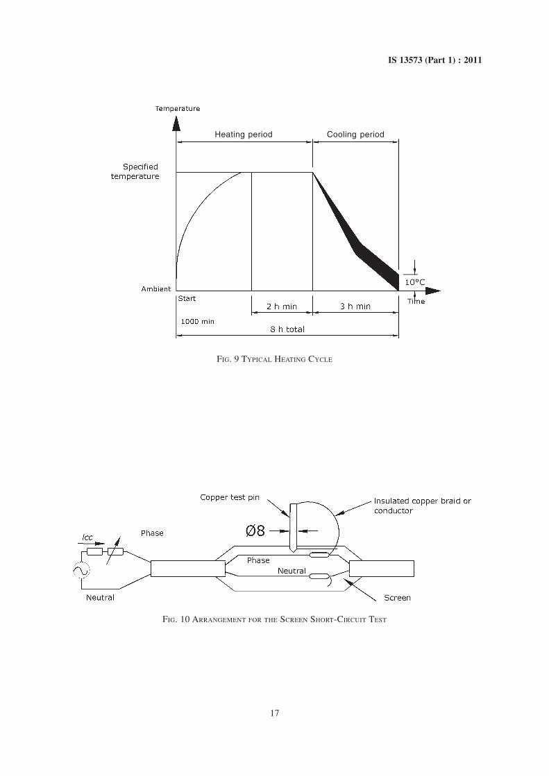
The total cycle shall be completed within 8 h. A typicalheating and cooling cycle is shown in Fig. 9.
Joints shall be subjected to 63 cycles in air followedby 63 cycles immersed in water. Branch cables≤ 50 mm2 shall not be heated.
Outdoor terminations shall be subjected to 63 cyclesin air followed by 63 cycles with the crutch onlyimmersed. For convenience, the ‘in air’ cycles may becarried out in the tank (without water), but provisionshall be made to allow air circulation.
NOTE — Care should be exercised if cable incorporatesmagnetic armouring.
8.3.3.1 In air
The temperature of the main conductors (and branchconductors when > 50 mm2) shall be raised to between5 and 10°C above the maximum rated temperature byheating the assembly, by passing current through thecables, as shown in Fig. 5 to 8, as appropriate. A steadyconductor temperature shall be maintained for not lessthan 2 h. After the 2 h minimum steady temperatureperiod the current shall be switched off and the cableallowed to cool naturally to within 10°C of ambientwithin a period not less than 3 h. Forced cooling shallnot be used.
8.3.3.2 In water
Joints: The core(s) of one polymeric insulated cable
shall be exposed at the entry to the joint by removingan annulus of the oversheath together with anybedding or filling material of at least 50 mm length ata point which will be within the water and between 50mm and 150 mm from the exterior of the accessory.The exposure of the core(s) shall be made on the sidewith the shorter sealing length between the sheath cutback and connectors. The assembly shall be placed ina water bath (or pressure vessel) with a water height
of h = 2001 000+
- mm or other wise specified above themain cable entry (see 6.1).
The over sheath damage requirement does not applyto water-blocked cable designs.
Outdoor terminations: The thermocouple shall beplaced as shown in Fig. 4. The water height over thecrutch shall be h = 300 ± 100 mm.
During the heating cycle the temperature of the watershall be 20 ± 15°C.
Conductor temperatures shall be recorded during eachof the 126 cycles. Any cycle during which the specifiedminimum conductor temperature is not reached shallbe rejected and additional cycles carried out to achievethe specified number.
8.4 Insulation Resistance Test
8.4.1 Purpose
To ensure that the insulation resistance has not beenimpaired by the mechanical and electrical tests.
8.4.2 Test Installation
Assemblies subjected to the test sequences.
8.4.3 Test Procedure
Insulation resistance shall be measured using aninstrument with an operating voltage in the range100 V to 1 000 V dc.
The dc test voltage shall be applied for sufficient timeto reach a steady measurement, but for not less than1 min and not more than 5 min. Insulation resistancemeasurements shall be made at ambient temperature.
8.4.3.1 Prior to immersion in water
The insulation resistance shall be measured betweeneach phase conductor in turn and the other phaseconductors, and between the bunched phase cores andall other metallic parts.
For the purpose of this part of the test the neutral shallbe treated as another phase core.
8.4.3.2 After immersion in water
The insulation resistance shall be measured betweeneach phase conductor in turn and the other phase

9
IS 13573 (Part 1) : 2011
conductors, and between the bunched phase conductorsand all other metallic parts and water.
For the purpose of this part of the test the neutral shallbe treated as another phase conductor providing thesheath damage in the load cycling test has not broughtit in contact with the water (that is in the case of cableswith a concentric neutral). If the neutral is in contactwith the water it shall be bunched with the othermetallic parts.
8.5 Impact at Ambient Temperature
Following two categories of joints or stop ends areconsidered:
a) Rigid joints and stop ends; and
b) Non-rigid joints and stop ends, incorporatinga metallic earth screen.
8.5.1 Purpose
The purpose of this test is to demonstrate the
mechanical strength of the joint or stop end at ambienttemperature.
8.5.2 Test Installation
The test shall be performed on all joints or stop endsto be subjected to the main test regime. The number ofimpacts shall be as specified below.
8.5.3 Test Procedure
8.5.3.1 Rigid joints and stop ends
The accessory shall be placed in a box on a hardsurface, for example a concrete slab or floor, and thebox shall be filled with sand to the horizontal centre ofthe accessory as shown in Fig. 1.
The impacting tool shall be a wedge-shaped steel blockof 4 kg mass having a 90° angle with a 2 mm radiusimpacting edge of minimum width 50 mm. The blockshall be dropped onto the accessory from a height of
+−2001 000 mm, so that the impacting edge is horizontal,
All dimensions in millimetres.
FIG. 1 ARRANGEMENT FOR THE IMPACT TEST AT AMBIENT TEMPERATURE

10
IS 13573 (Part 1) : 2011
at right angles to the axis of the accessory, and centeredon the point of impact.
The impact shall be made at the mid-point of theprimary moisture seal at each cable entry, and in themiddle of the joint near to the connector(s).
The accessory shall be immersed in water with a
height of +−2001 000 mm above the cable entry or such
other height as specified, for a minimum of 3 h beforecarrying out the a.c. voltage and insulation resistancetests. The time of immersion may be extended overone night for convenience.
8.5.3.2 Non-rigid joints and stop ends
The accessory shall be placed on a hard surface, forexample a concrete slab or floor.
The impacting tool shall be a wedge-shaped steelblock of 4 kg minimum having a 90° angle with a 2mm radius impacting edge of minimum width 50 mm.The block shall be dropped onto the accessory from aheight of +
−2001 000 mm so that the impacting edge is
horizontal, at right angles to the axis of the accessory,and centered on the point of impact.
The impact shall be made at each cable entry within10 mm of the edge of the oversheath on the joint side.In addition one impact shall be made over theconnector(s).
As far as practicable the accessory, at the point ofimpact, shall be in contact with the floor.
The accessory shall be immersed in water with a
height of +−2001 000 mm above the cable entry or such
other height as specified, for a minimum of 3 h beforecarrying out the ac voltage and insulation resistancetests. The time of immersion may be extended overone night for convenience.
8.6 ac Voltage Withstand Test
8.6.1 Purpose
The purpose of the test is to assess the integrity of theinsulation early in the test sequence and to identifydeterioration of the insulation as a result of themechanical and thermal stresses introduced during thetests.
8.6.2 Test Installation
Joints and stop ends: The test shall be carried outwhile immersed in the water bath (or pressure vessel),or in air as specified in Tables 3 and 4. For immersiondepth see Fig. 3.
Outdoor terminations: The test shall be carried out inair or with the crutch immersed in water as specifiedin Table 5. For immersion depth see Fig. 4.
8.6.3 Test Procedure
An ac voltage of 4 kV shall be applied for 1 minbetween the bunched phase conductors and all othermetallic parts and the water (if appropriate).
An ac voltage of 4 kV shall be applied for 1 min
All dimensions in millimetres.
NOTE — For convenience, this part of test may be conducted in the tank (without water).
FIG. 2 TYPICAL ARRANGEMENT FOR THE HEATING CYCLE IN AIR

11
IS 13573 (Part 1) : 2011
All dimensions in millimetres.
NOTES1 h = height of water, as specified in 6.1 and 8.6.3.
2 If pressure vessel is used it shall incorporate of registering pressure and water level.
FIG. 3 TYPICAL ARRANGEMENT FOR THE HEATING CYCLE FOR JOINTS IN WATER
between each phase conductor in turn and all otherphase conductors, metallic parts and water earthed.
In situations where the neutral is insulated from thewater, the neutral shall be treated as another phaseconductors for the purposes of this test.
8.7 Immersion Test
8.7.1 Purpose
The purpose of the test is to prove the satisfactorymoisture ingress performance of the stop ends.
8.7.2 Test Installation
The cores of the cable shall be exposed by removingan annulus of the oversheath and any bedding or fillingmaterial over a length of at least 50 mm, starting at apoint 50 mm from the cable entry.
The oversheath damage requirement does not applyto water-blocked cable designs.
The test sample shall be immersed in a water bath (orpressure vessel) with a height of 1 000 mm, or asotherwise specified, above the cable entry of the stopend (see 6.1). The sample shall remain immersed for21 days and during this time the temperature of thewater shall remain in the range 20 ± 15°C.
After 21 days the sample shall undergo the ac voltagewithstand test specified in 8.6 followed by insulation
resistance measurement in accordance with 8.4 whilestill immersed in the water bath.
8.8 Examination
8.8.1 Purpose
The purpose of the examination is to ascertain whetherany deterioration has taken place in the accessorywhich may affect its long term service life.
8.8.2 Examination Objects
The joints and outdoor terminations which have beensubjected to the heating cycle test and stop ends whichhave been subjected to the immersion test shall besectioned and examined.
8.8.3 Procedure
8.8.3.1 Rigid joints and stop ends
Dismantle the assemblies and examine the joint.
Section the joint at right angles to the cable axis atthe position of the phase conductor connector(s) andat the ends of the oversheath (polymeric insulatedcables) or the metallic sheath (paper insulated cables).Make two cuts at each position to give a cross-sectionof the joint approximately 25 mm thick.
Visually examine the encapsulant exposed at thesectioned ends of the joint for cracks and large voidsand if any are present, record details.

12
IS 13573 (Part 1) : 2011
All dimensions in millimetres.
NOTE — h = height of water (see also 8.3.3).
FIG. 4 TYPICAL ARRANGEMENT FOR THE HEATING CYCLE FOR OUTDOOR TERMINATIONS IN WATER

13
IS 13573 (Part 1) : 2011
FIG. 5 METHOD OF CONNECTION FOR THE HEATING CYCLE TEST oN BRANCH JOINT WHERE THE MAIN CABLE
CONDUCTOR CROSS-SECTION IS GREATER THAN 50 mm2 AND THE BRANCH CABLE CONDUCTOR CROSS-SECTION ISLESS THAN OR EQUAL TO 50 mm2 (EXAMPLE ONLY)
Examine the cross-section of each joint cable entry forwater ingress between the encapsulant and the cablesheath. Make two cuts approximately 45° apart aroundthe circumference down to the cable sheath. If possible,pull the 45° segment of encapsulant away from thecable sheath and scrutinize the interface surfaces thatare consequently exposed for moisture.
Examine the metalwork and in particular any neutralconductor or earth bonds for corrosion and record theresults of the examination.
NOTE — Where practicable the sectioning should be carriedout using hand tools rather than power tools, to avoidevaporating any moisture.
8.8.3.2 Non-rigid joints and stop ends
Examine the joint for the effectiveness of the moistureseals and corrosion of the armour bonds and othermetalwork exposed within the joint casing.
Check the outer sleeve or protection for any splitsand then remove it where it overlaps the cable oversheath.

14
IS 13573 (Part 1) : 2011
FIG. 6 METHOD OF CONNECTION OF THREE PHASE CABLES FOR THE HEATING CYCLE TEST ON A STRAIGHT JOINT
(EXAMPLE ONLY)
If the outer sleeve or protection comprises more thanone component (for example, two sleeves overlapped), similarly examine the seal(s) between thecomponents.
Remove the joint case (sleeve plus any metallic casing)to allow examination of the jointed conductors andany metalwork, for example armour bonds.
Remove the primary insulation over each conductorconnector (using heat, if necessary) and examine theseals.
Examine the metalwork, and in particular any neutralconductor or earth bonds for corrosion and record theresults of the examination.
NOTE — Since the design of the joint may allow moisture toenter the joint from the cable, it is essential that the primaryinsulation seals are shown to be effective in preventing moisturereaching the conductor connectors.
8.8.3.3 Outdoor terminations
The termination shall be dismantled and allcomponents shall be examined for traces of moisturewithin water-proofing components. The results of theexamination shall be recorded.
8.9 Metallic Screen Short-Circuit CurrentWithstand Test
8.9.1 Purpose
To check that when the joint is pierced by a metallic

15
IS 13573 (Part 1) : 2011
FIG. 7 METHOD OF CONNECTION OF THREE PHASE MAIN AND BRANCH CABLES OF EQUAL CONDUCTOR
CROSS-SECTION FOR HEATING CYCLE TEST ON A BRANCH JOINT (EXAMPLE ONLY)
hand tool the circuit protection operates beforedisintegration of the screen. It is applicable to straightand branch joints only where the conductor cross-sectionis 150 mm2 and above, on networks protected by fuses.The size of fuse to be used in the test shall be subject toagreement between the customer and the manufacturer.
8.9.2 Test Installation
The general arrangement of the test joint, includingresistance and fuse, is shown in Fig. 10.
Two joints shall be made which shall be additional tothose subjected to the main test regime.

16
IS 13573 (Part 1) : 2011
FIG. 8 METHOD OF CONNECTION OF THREE PHASE MAIN AND BRANCH CABLES OF UNEQUAL CONDUCTOR
CROSS-SECTION FOR HEATING CYCLE TEST ON A BRANCH JOINT (EXAMPLE ONLY)
During the making of each joint, a length of insulatedcopper braid or conductor of a minimum cross-sectional area of 50 mm2 shall be connected to onephase and brought out of the joint to be connected toa 8 mm diameter copper test pin.
A hole of maximum diameter 6 mm shall be drilledinto the joint so that the test pin may be inserted tomake connection with the screen.
8.9.3 Test Procedure
The current source shall be set up to deliver a phaseto earth short-circuit current, Isc, the value to be agreedbetween the customer and the manufacturer. The opencircuit voltage between the test phase and earth shallbe 230 V.
The short-circuit current and the voltage shall remainin phase throughout the test.
17
IS 13573 (Part 1) : 2011
FIG. 9 TYPICAL HEATING CYCLE
FIG. 10 ARRANGEMENT FOR THE SCREEN SHORT-CIRCUIT TEST
Heating period Cooling period

18
IS 13573 (Part 1) : 2011
ANNEX A(Clauses 8.1.2.3 and 8.3.2)
DETERMINATION OF THE CABLE CONDUCTOR TEMPERATURE
A-1 PURPOSE
For some of the accessory tests, it is necessary to raisethe cable conductor to a given temperature, typically 5to 10°C above the maximum temperature in normaloperation, while the cable is energized, either at powerfrequency or under impulse conditions. It is thereforenot possible to have access to the conductor to enabledirect measurement of temperature.
In addition, the conductor temperature should bemaintained within a restricted range (5°C), whereasthe ambient temperature may vary over a wider range.
Thus, it is necessary to carry out a preliminarycalibration on the test cable to determine the actualconductor temperature during the accessory tests,allowing for the permitted variation in ambienttemperature.
Guidance is given hereafter on commonly usedmethods.
A-2 CALIBRATION OF THE TEST CABLECONDUCTOR TEMPERATURE
The purpose of the calibration is to determine theconductor temperature by direct measurement for agiven current, within the temperature range requiredfor the test.
The cable used for calibration should be identical tothat to be used for the accessory test.
A-2.1 Installation of Cable and Thermocouples
The calibration should be performed on a minimumcable length of 2 m, the thermocouples being installedat 0.5 m from the cable ends, as shown in Fig. 11.
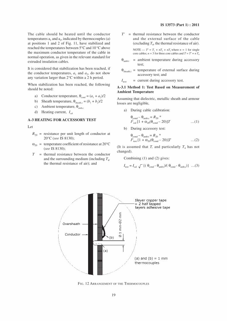
At each place, two thermocouples should be attached:one on the conductor (a), and one on the externalsurface (b), as shown in Fig. 12.
It is recommended that the thermocouples are attachedto the conductor by mechanical means since they maymove due to vibrations of the cable conductor duringheating.
If the actual test loop includes several individual cablelengths installed close to each other, these lengths willbe subjected to thermal proximity effect. Thecalibration should therefore be carried out takingaccount of the actual test arrangement, measurementsbeing performed on the hottest cable length (usuallythe middle length).
NOTE — The thermocouples (b) on the external surface areonly necessary, if method A-3.2 is used.
A-2.2 Method
The calibration should be carried out in a draught freesituation at a temperature between 5°C and 35°C.
Temperature recorders should be used to measure theconductor, sheath and ambient temperatures.
FIG. 11 REFERENCE CABLE
19
IS 13573 (Part 1) : 2011
The cable should be heated until the conductortemperatures a1 and a2, indicated by thermocouples (a)at positions 1 and 2 of Fig. 11, have stabilized andreached the temperatures between 5°C and 10 °C abovethe maximum conductor temperature of the cable innormal operation, as given in the relevant standard forextruded insulation cables.
It is considered that stabilization has been reached, ifthe conductor temperatures, a1 and a2, do not showany variation larger than 2°C within a 2 h period.
When stabilization has been reached, the followingshould be noted:
a) Conductor temperature, θcond = (a1 + a2)/2b) Sheath temperature, θsheath.c = (b1 + b2)/2c) Ambient temperature, θamb.c
d) Heating current, Ical
A-3 HEATING FOR ACCESSORY TEST
Let
R20 = resistance per unit length of conductor at20°C (see IS 8130);
α20 = temperature coefficient of resistance at 20°C(see IS 8130);
T = thermal resistance between the conductorand the surrounding medium (including T4,the thermal resistance of air); and
T' = thermal resistance between the conductorand the external surface of the cable(excluding T4, the thermal resistance of air).
NOTE — T' = T1 + nT2 + nT3 where n = 1 for singlecore cables; n = 3 for three core cables and T = T' + n T4
θamb.t = ambient temperature during accessorytest;
θsheath.t = temperature of external surface duringaccessory test; and
Itest = current during accessory test.
A-3.1 Method 1: Test Based on Measurement ofAmbient Temperature
Assuming that dielectric, metallic sheath and armourlosses are negligible,
a) During cable calibration:
θcond – θamb.c = R20 *I2
cal [1 + α20(θcond – 20)]T …(1)
b) During accessory test:
θcond – θamb.t = R20 *I2
test [1 + α20(θcond – 20)]T …(2)
(It is assumed that T, and particularly T4 has notchanged).
Combining (1) and (2) gives:
Itest = Ical {( θcond - θamb.t)/( θcond - θamb.c)} …(3)
FIG. 12 ARRANGEMENT OF THE THERMOCOUPLES

20
IS 13573 (Part 1) : 2011
A-3.2 Method 2: Test Based on Measurement of theExternal Surface Temperature
a) During cable calibration:θcond – θsheath.c = R20 *I2
cal [1 + α20(θcond – 20)]T' …(4)
b) During accessory test:
θcond – θsheath.t = R20 *I2
test [1 + α20(θcond – 20)]T' …(5)
Combining (4) and (5) gives:
Itest = Ical {( θcond – θsheath.t)/( θcond -
θsheath.c)} …(6)
It should be noted that equation (4) allows thedetermination of the internal thermal resistance T’ ofthe cable from readings of temperature and current.
Equation (5) can be written in the form:
θcond = [θsheath.t + (1 – 20α20) R20 I2test
T'] / [1– α20 R20 I2
test T'] … (7)
It is therefore possible to transpose this formula in theform of chart, as shown in Fig. 13, giving θcond fromθsheath.t readings, for various values of the heatingcurrent Itest1, Itest2, …………..
The use of such a chart is advisable, if the test is notautomatically controlled.
A-3.3 Method 3: Test Using a Control Cable
In this method, a control cable identical to the cableused for the test is heated with the same current as thetest loop. The cable is not energized and thereforethermocouples can be fitted to the conductor asrecommended in A-2.1.
The test arrangement should be such that,
a) the control cable should carry the same currentas the test loop at any time, and
b) it should be installed in such a way that mutualheating effects are taken into accountthroughout the test.
FIG. 13 CURRENT/TEMPERATURES CURVES

21
IS 13573 (Part 1) : 2011
The thermocouples should be mounted on the externalsurface of the test loop at the positions given in Fig. 11,in the same way as the thermocouples are mounted onor under the surface of the control cable.
The temperature measured with the thermocouple fittedto the conductor of the control loop may be consideredas representative for the conductor temperature of theenergized test loop.
All thermocouples should be connected to a temperaturerecorder to enable temperature monitoring. The heating
current of each test loop should be recorded to provethat the two currents are of the same value throughoutthe duration of the test. The difference between theheating currents should be kept within ±1 percent.
The heating current is adjusted so that the conductortemperature is kept within the specified limits.
NOTE — The temperature measured with the thermocoupleson the oversheath of the energized test loop and of the controlcable, are used to check whether the oversheath of both testloops has the same temperature.

Bureau of Indian Standards
BIS is a statutory institution established under the Bureau of Indian Standards Act, 1986 to promoteharmonious development of the activities of standardization, marking and quality certification of goodsand attending to connected matters in the country.
Copyright
BIS has the copyright of all its publications. No part of these publications may be reproduced in any formwithout the prior permission in writing of BIS. This does not preclude the free use, in the course ofimplementing the standard, of necessary details, such as symbols and sizes, type or grade designations.Enquiries relating to copyright be addressed to the Director (Publications), BIS.
Review of Indian Standards
Amendments are issued to standards as the need arises on the basis of comments. Standards are also reviewedperiodically; a standard along with amendments is reaffirmed when such review indicates that no changes areneeded; if the review indicates that changes are needed, it is taken up for revision. Users of Indian Standardsshould ascertain that they are in possession of the latest amendments or edition by referring to the latest issue of‘BIS Catalogue’ and ‘Standards : Monthly Additions’.
This Indian Standard has been developed from Doc No.: ETD 09 (5976).
Amendments Issued Since Publication
Amend No. Date of Issue Text Affected
BUREAU OF INDIAN STANDARDS
Headquarters:
Manak Bhavan, 9 Bahadur Shah Zafar Marg, New Delhi 110002Telephones : 2323 0131, 2323 3375, 2323 9402 Website: www.bis.org.in
Regional Offices: Telephones
Central : Manak Bhavan, 9 Bahadur Shah Zafar Marg 2323 7617NEW DELHI 110002 2323 3841
Eastern : 1/14 C.I.T. Scheme VII M, V. I. P. Road, Kankurgachi 2337 8499, 2337 8561KOLKATA 700054 2337 8626, 2337 9120
Northern : SCO 335-336, Sector 34-A, CHANDIGARH 160022 60 384360 9285
Southern : C.I.T. Campus, IV Cross Road, CHENNAI 600113 2254 1216, 2254 14422254 2519, 2254 2315
Western : Manakalaya, E9 MIDC, Marol, Andheri (East) 2832 9295, 2832 7858MUMBAI 400093 2832 7891, 2832 7892
Branches: AHMEDABAD. BANGALORE. BHOPAL. BHUBANESHWAR. COIMBATORE. DEHRADUN.FARIDABAD. GHAZIABAD. GUWAHATI. HYDERABAD. JAIPUR. KANPUR. LUCKNOW.NAGPUR. PARWANOO. PATNA. PUNE. RAJKOT. THIRUVANANTHAPURAM.VISAKHAPATNAM.
�
��
�
�
Published by BIS, New Delhi