is 13048 (1991): recommendations for hydraulic design of ... · the duckbill spillways is a...
TRANSCRIPT

Disclosure to Promote the Right To Information
Whereas the Parliament of India has set out to provide a practical regime of right to information for citizens to secure access to information under the control of public authorities, in order to promote transparency and accountability in the working of every public authority, and whereas the attached publication of the Bureau of Indian Standards is of particular interest to the public, particularly disadvantaged communities and those engaged in the pursuit of education and knowledge, the attached public safety standard is made available to promote the timely dissemination of this information in an accurate manner to the public.
इंटरनेट मानक
“!ान $ एक न' भारत का +नम-ण”Satyanarayan Gangaram Pitroda
“Invent a New India Using Knowledge”
“प0रा1 को छोड न' 5 तरफ”Jawaharlal Nehru
“Step Out From the Old to the New”
“जान1 का अ+धकार, जी1 का अ+धकार”Mazdoor Kisan Shakti Sangathan
“The Right to Information, The Right to Live”
“!ान एक ऐसा खजाना > जो कभी च0राया नहB जा सकता है”Bhartṛhari—Nītiśatakam
“Knowledge is such a treasure which cannot be stolen”
“Invent a New India Using Knowledge”
है”ह”ह
IS 13048 (1991): Recommendations for hydraulic design ofduck bill spillways [WRD 9: Dams and Spillways]


Indian Standard
RECOMMENDATIONSFORHYDRAULIC DESIGNOFDUCKBILL SPILLWAYS
UDC 627.83 1
@ BIS 1991
BUREAU OF INDIAN STANDARDS MANAK BHAVAN, 9 BAHADUR SHAH ZAFAR MARG
NEW DELHI 110002
Price Group 2

Spillways Including Energy Dissipators Sectional Committee, RVD 10
FOREWORD ’
This Indian Standard was adopted by the Bureau of Indian Standards, after the draft finalized by the Spillways Including Energy Dissipators Sectional Committee had been approved by the River Valley Division Council.
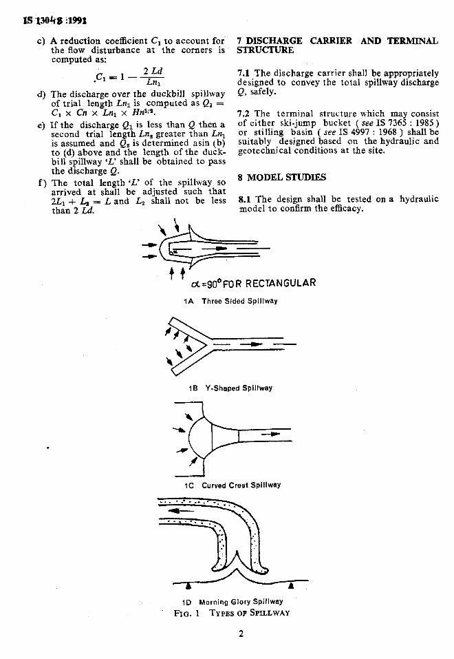
Discharging large floods can be accomplished by increasing either the spillway crest length or operating head. In practice increasing this head is achieved by using gated spillways. By this selection, it is possible to increase significantly the unit discharge of the crest. Therefore, if the crest and chute width are reduced, gated spillways may result in significant cost reduction over uncontrolled straight crests. When the spillway is located in remote area where electric power supply, man-power, etc, are scarce and/or the submergence in the upstream is not a problem, it is desirable to use an uncontrolled crest. To increase the crest length of uncontrolled spillways, in a comparatively small lateral space, different types of crest shapes have been developed. Three-sided spillways ( rectangular or trapezoidal shape in plan), Y-shaped spillways and curved crest spillways are examples of such development ( Fig. 1 ). The duckbill spillways is a three-sided spillway and projects into the reservoir water spread. The surplussing water flows over the sides and is collected in a gathering trough and conveyed through a chute on to a terminal structure which may be a stilling basin or a roller or ski-jump bucket. Series ofduckbill spillway can be termed as labyrinth weir. The recommendations for hydraulic design of only duckbill spillway are given in this standard.
Ideally the discharge over the duckbill spillway should increase in direct proportion to an increase in total crest length. However, this is only applicable for spillway with low design head. As the upstream head over the crest increases and forms a solid and non-aerated nappe, the flow would be in a suppressed phase and efficiency of the spillway decreases approaching that of a straight crest with a length equal to the chute width. Hence duckbill spillway is advantageously provided where free flow exists. It is not recommended to provide this type of spillway where it would usually be subjected to operation under heavily drowned flow conditions. However, model studies are essential to check the efficiency of the spillway design.
This type of spillway can be economically located in the flanks of earth and rockfill dams as it results in a considerable reduction in the excavation, both in the approach and tail channel, when compared with straight spillways or side-channel spillways. This type of spillways may be advantageous where maximum allowable afflux is limited. It also increases storage capacity because the crest level can be fixed at higher level for the same maximum water level. On the other hand, as it can pass floods at lower head compared to normal weir, the MWL is lowered and consequently height of the dam can be reduced thus affecting a saving in cost of construction and reduction in the submergence.

REC;O;MMENDATIONSFORHYDRAULIC D'ESIGNOFDUCKBILL SPILLWAYS
1SCOPE
1.1 This standard recommends criteria to be adopted for the hydraulic design of duckbill spillways.
2 REFERENCES
2.1 The following Indian Standards are necess- ary adjuncts to this standard:
IS No:
4997 : 1968
6934 : 1973
7365 : 1985
Title
Criteria for design of hydraulic jump type stilling basins with horizontal and sloping apron Recommendations for hydraulic design of high ogee overflow spillways Criteria for hydraulic design of bucket type energy dissipators ( jsrst revision )
3 NOTATIONS
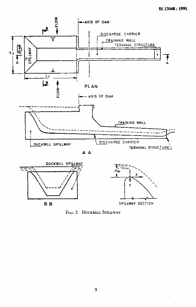
3.1 For the purpose of this standard the follow- ing notations shall have the meaning indicated against each ( see Fig. 2 ).
Ln =
Lnl and Lnl, - etc
Cn =
Q =
Hn =
Q1, Q,, etc =
Ll and Lt =
L =
Ld
Cl =
Theoretical length of normal straight spillway in m The trial lengths of the duck- bill spillway in m
Coefficient of discharge for the normal straight spillway Peak flood to be surplussed in cumecs “. Depth of flow over the normal straight spillway in In
Discharge over the duckbill spillway corresponding to length Lnl, Ln2, etc, in cumecs
Dimension of the segments of the crest length Total length of duckbill spill- way - 2L1 i- La Length of disturbance of flow at the corners in case of polygonal shapes. Coefficient of reduction for the duckbill spillway to be applied for Cn
a andb = Constants to be obtained from Fig. 3 and 4 for poly- gonal shape
= Corner angle of the duckbill. spillway
= 90 degrees for rectangular
4 TERMINOLOGY
4.0 For the purpose of this standard, the follow- ing definitions shall apply.
4.1 Duckbill Spillway
This is a spillway with a rectangular layout projections into the reservoir comprising three straight overflow lengths intersecting at right angles. The layout could be trapezoidal in which case the corner angles will be other than 90 degree. The flow from the three reaches of the spillway interacts in the trough portion and is further conveyed through a discharge carrier on to a terminal structure to provide for dissipation.
4.2 Trough
L energy
The trough of the duckbill spillway is by the intersection of the downstream of the three straight length.
5 PROFILE
formed profiles
5.1 Normally the crest profile formed of com- pound circular curve is adopted. However, the ogee profile, if provided, shall be in conformity with IS 6934 : 1973.
6 DISCHARGE COMPUTATIONS
6.1 The peak discharge Q for a normal straight spillway. _&length Ln with head Hn shall be computed from the equation:
Q = Cn Ln HrW based on the recommenda- tions made in IS 6934 : 1973.
6.2 The length of the duckbill spillway to pass the discharge Q at a head equal to Hn is deter- mined as described below:
a)
b)
Assume a trial length Lnl of the duckbill spillway greater than Ln.
The length of disturbance Ld is deter-
mined as Ld = (T3
The values of
a and b for various corner angles shall be obtained from Fig. 3 and 4.
1
lsW048:19!u .> , ,
A reduction coefficient C, to account for the flow disturbance at the corners is computed as:
2 Ld *Cl = 1 - z
1
The discharge over the duckbill spillway of trial length Lnl is computed as Q1 = C1 x Cn x Lnl x HrW.
If the discharge Q, is less than. Q then a second trial length Ln, greater than Ln, is assumed and QS is determined asin (b) to (d) above and the length of the duck- bill spillway ‘L’ shall be obtained to pass the discharge Q. The total length ‘L’ of the spillway so arrived at shall be adjusted such that 2Li -l- L, = L and La shall not be less than 2 Ld.
.
7 DISCHARGE CARRIER AND TERMINAL STRUCTURE
7.1 The discharge carrier shall be appropriately designed to convey the total spillway discharge Q, safely.
7.2 The terminal structure which may consist of either ski-jump bucket ( see IS 7365 : 1985 ) or stilling basin ( see IS 4997 : 1968 ) shall be suitably designed based on the hydraulic and geotechnical conditions at the site.
8 MODEL STUDIES
8.1 The design shall be tested on a hydraulic model to confirm the efficacy.
I I
d=90°fOR RECTANGULAR
IA Three Sided Spillway
1B Y-Shaped Spillway
IC Curved Crest Spillway
ID Morning Glory Spillway
FIG. 1 TYPES OF SPILLWAY
IS13048:1993"
t- AXIS OF DAM
CARRIER DISCHARGE
T TRAINING WALL
TERMINAL STRUCTURE , c I 1
I ‘i I I l
I/ 1 f
I
PLAN
t_ AXlS
7 A
OF DAM
_-_‘ ;_________ ____ ____i--fl
TRAINING WALL
._ 7
---------w--e_____ -------__-____ -_ ___--#
b
DUCKBILL SPILLWAY DISCHARGE CARRIER
TERMINAL STRUCTURE
AA
OUCKBILL SPILLWAY
FIG. 2 DUCKBILL SPILLWAY
3

2*5
200
t l-5
a
7-o
O*O
CORNER ANGLE t~( -
FIG. 3 CONSTANT ‘Q’
0.0 0
t
0*8f
b 0.80
OS75
O-70 q o” 45O 90* 135O 180°
CORNER ANGLE d --
FIG. 4 CONSTANT ‘b’

.
Stassdard Mark The use of the Standard Mark is governed by the provisions of the Bureau of Indian Standards
Act, 1986 and the Rules and Regulations made thereunder. The Standard Mark on products covered by an Indian Standard conveys the assurance that they have been produced to comply with the requirements of that standard under a well defined system of inspection, testing and quality control which is devised and supervised by BIS and operated by the producer. Standard marked products are also continuously checked by BIS for conformity to that standard as a further safeguard. Details of conditions under which a licence for the use of the Standard Mark may be granted to manufacturers or producers may be obtained from the Bureau of Indian Standards.

Bureau of Indian Standarda
BIS is a statutory institution established under the Bureau of Indian Standards Act, 1986 to promote harmonious development of the activities of standardization, marking and quality certification of goods and attending to connected matters in the country.
Copyright l
BIS has the copyright of all its publications. No part of these publications may be reproduced in any form without the prior permission in writing of BIS. This does not preclude the free use, in the course of implementing the standard, of necessary details, such as symbols and sizes, type or grade designations, Enquiries relating to copyright be addressed to the Director ( Publications ), BIS.
Revision of Indian Standards
Indian Standards are reviewed periodically and revised, when necessary and amendments, if any, are issued from time to time. Users of Indian Standards should ascertain that they are in possession of the latest amendments or edition. Comments on this Indian Standard may be sent to BIS giving the following reference:
Dot : No. RVD 10 ( 4504 )
Amendments Issued Since Publication
Amend No. Date of Issue Text Affected
BUREAU OF INDIAN STANDARDS
Headquarters :
Manak Bhavan, 9 Bahadur Shah Zafar Marg, New Delhi 110002 Telephones : 331 01 31, 331 13 75
Telegrams : Manaksanstha ( Common to all Offices )
Regional Offices : Telephone
Central : Manak Bhavan, 9 Bahadur Shah Zafar Marg 331 01 31 NEW DELHI 110002 331 13 75
Eastern : l/14 C. I. T. Scheme VII M, V. I. P. Road, Maniktola CALCUTTA 700054
87 86 62
Northern : SC0 445-446, Sector 35-C, CHANDIGARH 160036 53 38 43
Southern : C. I. T. Campus, IV Cross Road, MADRAS 600113
Western : Manakalaya, E9 MIDC, Marol, Andheri ( East ) BOMBAY 400093
41 29 16
. 6 32 92 95
Branches : AHMADABAD. BANGALORE. BHOPAL. BHUBANESWAR. COIMBATORE. FARIDABAD. GHAZIABAD. GU WAHATI. HYDERABAD. JAIPUR. KANPUR. PATNA. THIRUVANATHAPURAM.
Printed at New India Printing Press,fKhorja. India