is 1068 (1993): eletroplated coatings of nickle plus
TRANSCRIPT

Disclosure to Promote the Right To Information
Whereas the Parliament of India has set out to provide a practical regime of right to information for citizens to secure access to information under the control of public authorities, in order to promote transparency and accountability in the working of every public authority, and whereas the attached publication of the Bureau of Indian Standards is of particular interest to the public, particularly disadvantaged communities and those engaged in the pursuit of education and knowledge, the attached public safety standard is made available to promote the timely dissemination of this information in an accurate manner to the public.
इंटरनेट मानक
“!ान $ एक न' भारत का +नम-ण”Satyanarayan Gangaram Pitroda
“Invent a New India Using Knowledge”
“प0रा1 को छोड न' 5 तरफ”Jawaharlal Nehru
“Step Out From the Old to the New”
“जान1 का अ+धकार, जी1 का अ+धकार”Mazdoor Kisan Shakti Sangathan
“The Right to Information, The Right to Live”
“!ान एक ऐसा खजाना > जो कभी च0राया नहB जा सकता है”Bhartṛhari—Nītiśatakam
“Knowledge is such a treasure which cannot be stolen”
“Invent a New India Using Knowledge”
है”ह”ह
IS 1068 (1993): Eletroplated coatings of nickle pluschromium and copper plus nickel plus chromium [MTD 7: LightMetals and their Alloys]


IS 1068:1993 ( Superseding Is 4827, I8 4828 and IS 4842 )
Indian Standard
ELECTROPLATED COATINGS OF NICKEL PLUS CHROMIUM AND COPPER PLUS
NICKEL PLUS CHROMIUM-SPECIFICATION (, Third Revision )
Second Reprint APRIL 1998
669’248’7’26 + 669’387’24’25 : 621’357’7
8 BIS 1993
BUREAU OF INDIAN STANDARDS MANAK BHAVAN, 9 BAHADUR SHAH ZAFAR MARG
NEW DELHI 110002
July 1993 Price Group 7

Metallic and Non-Metallic Sectional Commi(tee, MTD 20
FOREWORD
This Indian Standard (Third Revision) was adopted by the Bureau of Indian Standards, after the draft finalized by the M,etallic and Non-Metallic Firlis!les Sectional Committee had been approved by the Metallurgical Engineering Division Council.
This standard was first published in 1958 and subsequently revised in 1968 and 1985, respectively. Electrodeposited coatings of Ni plus Cr and Cu + Ni + Cr that are applied to zinc alloys, copper and copper alloys, and aluminium and aluminium alloys which are presently covered in IS 4827, IS 4828 and IS 4942 respectively, have now been incorporated in this revision to have unification of the requirements of these coatings on line with International Standards.
After the publication of this standard, IS 4827 : 1983 ‘Electroplated coatings of nickel and chromium on copper and copper alloys (jirst revision )‘, IS 4828 : 1983 ‘Electroplated coatings of copper, nickel and chromium on zinc alloys (first revision )’ and IS 4942 : 1983 ‘Electroplating coating of nickel and chromium on aluminium and aluminium alloys (Jim revision )’ shall be withdrawn.
In the preparation of this standard considerable assistance has been derived from IS0 1456 : 1988 Metallic coatings - Electroplated coatings of nickel plus chromium and of copper plus nickel PIUS chromium.
For the purpose of deciding whether a particular requirement of this standard is complied with, the final value, observed or calculated, expressing the result of a test or analysis, shall be rounded off in accordance with IS 2 : 1960 ‘Rules for rounding off numerical values ( revised )‘. The number of significant places retained in the rounded off value should be the same as that of the specified value in this standard.

IS 1068 :. 1993
Indian Standard
ELECTROPLATED COATINGS OF NICKEL PLUS CHROMIUM AND COPPER PLUS
NICKEL PLUS CHROMIUM -SPECIFICATION
( Third Revision )
1 SCOPE
1.1 This standard covers requirements for nickel plus chromium and for copper plus nickel plus chromium electrodeposited coatings that are applied to iron, steel, zinc alloys, copper and copper alloys, and aluminium and aluminium alloys to provide an attractive appearance and corrosion resistance. Several classes of coatings are provided that differ in thickness and type and guidance is given in selecting the coating class appropriate to the service conditions to which the coated product will be exposed.
1.2 This standard does not specify the surface condition required by the basis metal prior to the coating process.
1.3 This standard is not applicable to coatings on sheet, strip or wire in the unfabricated form nor to threaded fasteners or coil springs.
2 REFERENCES
2.1 The standards given below are necessary adjuncts to this standard:
IS No.
3203 : 1982
5528 : 1985
6009 : 1970
6910 : 1985
8038 : 1985
Title
Methods of testing local thickness of electroplated coatings ( first revision )
Method of testing corrosion resistance of electroplated and anodized aluminium coating by copper accelerated acetic acid salt spray (CASS) test (first revision )
Method for evaluation of results of accelerated corrosion tests
Method of testing corrosion resistance of electroplated and anodized aluminium coatings by acetic acid salt spray test ( first revision )
Method of testing corrosion. resistance of metallic and non- organic coatings by corrodkote test ( first revision )
3 SIGNIFICANT SURFACE
3.1 For the purpose of this standard, a significant surface is defined as the part of surface of an article which being essential to the appearance or service- ability of that article is required to be coated by a specil”red thickness of copper, nickel and chromium, in the stipulated combinations as specified in Tables 1A to 4.
3.1.1 When necessary, the significant surface should be the subject of agreement, and should be indicated on drawings, or by the provision of suitably marked samples.
4 INFORMATION TO BE SUPPLIED BY THE PURCHASER TO THE ELECTROPLATER
4.1 Essential Information
When ordering articles to be electroplated in accordance with this standard, the purchaser shall provide the following information.
4.1.1 The number of this standard.
4.1.2 The basis metal and either the service condition number (See 5.1) denoting the severity of the conditions to be withstood by the coated arl.icle or the classification code (see 5.2) of the particular coating required.
If the basis metal and the service condition number are quoted and not the classification code, the electroplater is free to supply any of the classes of coating corresponding to the service condition number, but he shall inform the purchaser of the classification code of the coating which he has selected (see also 7.2).
4.1.3 The finish required, for example, bright, dull, or satin (see 7.2). Alternatively samples showing the required finish or range of finish shall be supplied or approved by the purchaser.
4.1.4 Significant surfaces, to be indicated on drawings of the parts, or by the provision of suitably marked specimens.
4.1.5 The type of corrosion test to be used.
1

IS 1068 : 1993
4.1.6 The type of adhesion test to be used.
4.1.7 The extent to which defects shall be tolerated on non-significant surfaces.
4.1.8 The positions on the significant surface for rack or contact marks, where such marks are unavoidable.
4.1.9 Sampling methods and acceptance levels.
4.2 Additional Information
The following additional information may be provided by the purchaser, when appropriate.
4.2.1 The tensile strength of the steel and any requirement for heat treatment either before or after electroplating.
4.2.2 Thickness requirements on those areas, that cannot be touched by a ball 20 mm in diameter.
4.23 Whetber or not a copper undercoat is required.
5 CLASSIFXCATION~
5.1 Service Condition Number
The service condition number is used by the purchaser to specify the degree of protection required, as related to the severity of the conditions to which a product is to be subjected, in accordance with the fdlOWinlj scale:
4 = Extremely severe
3 = Severe
2 = Moderate
1 = Mild
0 = Bxceptionally mild
Typical service conditions for which the various service con&ion numbers are appropriate are listed in Annex A.
5.2 Coating Classification Code
?be coating classification code comprise the following:
4
b)
The chemical symbol for the basis metal (or for the principal metal if an alloy) followed by a ’ stroke, as follows:
- Fe / for iron or‘ steel - Zn I for zinc alloys - Cu / for copper or copper alloys - Al / for aluminium or aluminiunt alloys
The chemical symbol for copper (Cu), if copper or brass containing greater than 50 percent copper, is used as an undercoat
2
4
4 4
0
g) hl
A number indicating the minimum local thickness, in micmmetres, of the copper coating where applicable.
The chemical symbol for nickel (Ni).
A number indicating the minimum local thickness, in micrometres, of the nickel coating.
A letter designating the type of nickel coating (see 7.2.3.2).
The chemical symbol for chromium (Cr).
A letter or letters designating the type of chromium coating and its minimum thickness.
Example of complete classification code : A coating on steel comprising 20 urn copper (minimum) plus 30 m bright nickel (minimum) plus 0.3 urn micro- cracked chromium (minimum) has the classification code.
Fe/Cu%O Ni30b Cr mc
NOTE - For nickel plus chromium and copper plus nickel plus chromium coatings, the minimum thickness requirements apply only to those portions of the significant surface that can be toucbed by a ball 20 mm in diameter unless otherwise specified by the purchaser.
5.3 Coating Appropriate to Each Service Condition NMBnhgf
Tables 1A to 4 show, for various basis metals, the coating classification codes appropriate for each service condition number.
6 HEAT TREATMENT OF STEEL
6.1 If the purchaser specifies tbat heat treatment is necessary before and/or after electroplating, it shall bc carried out in accordance with the appropriate recommendations given in Annex B.
7 COATING REQUIREMENTS
7.1 Appearance
Over the significant surface, there shall be no clearly visible plating defects such as blisters, pits, roughness, cracks, unplated areas, stains or discoloration. The extent to which defects may occur on non-significant surfaces shall be specified by the purchaser. Where rack marks on the significant surface are unavoidable, their position shall be specified by the purchaser.
7.2 Thickness and Type of Coatings
7.2.1 General
For a specified service condition number, the thickness and type of coating shall correspond to the classification codes given in Tables 1A to 4. The minimum allowable thickness for the metal coatings shall be required on any point of the significant surface that can -be touched by a ball 20 mm in diameter and the purchaser may also specify that other points shall meet those thickness requirements.

Test methods for detemtining coating thickness are specified in 9.1.
Table 2A Nickel Plus Chromium Coatings on Zinc Alloys
(Clauses 3.1, 5.3, 7.2.1, 7.2.2 and 7.2.4.1) Table 1A Nickel Plus Chmmium Coatin@
on Iron or Steel (Clauses 3.1, 5.3, 7.2.1 and 7.2.4.1)
Service ComdlUom ClmssUhUom
Namtbcr Code
4 FeiTVi 4Od Cr I Fe/Ni 306 Cr mc Fe/T% 30d Cr mp
Fe/M 4Op Cr r Fe/Ni 3op Cr mc
Fe/Ni 3@ Cr mp
Fe/Ni 30d Cr r FeJNi 2Sd Cr mc Fe-/Ni 2M Cr mp
FefTVi 30p Cr r Fe/M 25p Cr mc
Fe/Ni 25p Cr mp
Fe/Ni 4Ob Cr r Fe/Ni 30b Cr mc FeiNi 30b Cr mp
2 FeiNi 2Ob Cr r
i Fe/Ni 10b Cr r
0 Fe/Ni 05b Cr r
NOTE - s Nickel may be substituted for b nickel, and mc or mp chromium may be substituted for r chromium for service conditions 3, 2, 1 and 0. p and d nickel may be substituted for b nickel for service conditions 2 and 1.
h-vice Comditiom
Number CIasaUlat&m ’ Code
Zn/Cu Ni 35d Cr r ZtQCu Ni 25d Cr mc ZnKu Ni 25d Cr mp
4
Z&u Ni 35p Cr r Z&u Ni 25p Cr mc ZtuCu Ni 25p Cr mp
Zn/Cu Ni 35b Cr mc Zn/Cu Ni 35b Cr mp
Zm’Cu Ni 25d Cr r Zn/Cu Ni 20d Cr mc Zn/Cu Ni 206 Cr mp
Z&u Ni 25p Cr r Zn/Cu Ni 2Op Cr mc Z&u Ni 20p Cr mp
Zn/Cu Ni 35b Cr r ZnKu Ni 25b Cr mc Z&u Ni 25b Cr mp
Table 1B Copper Plus Nickel Plus Chromium Coatings on Iron or Steel
(C&/ties 3.1, 5.3, 7.2.1, 7.2.2 and 7.2.4.1)
Service Comditiom ClmssUiatIom
NUlllbW Code
Fe/Cu 20 Ni 3Od Cr r Fe/Cu 20 Ni 25d Cr mc FeKu 20 Ni 25d Cr mp
4 Fe/Cu 20 Ni 3Op Cr r Fe/Cu 20 Ni 25p Cr mc Fe/Cu 20 Ni 25p Cr mp
Fe/Cu 20 Ni 30b Cr mc Fe/Cu 20 Ni 30b Cr mp
2
0 and 1
NOTES
Zn/Cu Ni 15b Cr r
Zn/Cu Ni Oftb Cr r
1 s nickel may be substituted for b nickel, and mc or mp chromium may be substituted for r chromium for service conditions 3, 2 and 1. p and d nickel may be substituted for b nickel for service condition 2.
2 Thinner coatings than those given for service condition 1 are not specified for service condition 0.
3 A copper undercoat of at least 8 pm shall be given in all the cases.
7.2.2 Thickness of Copper Coating
3
Fe/Cu 15 Ni 25d Cr r Fe/C% 15 Ni 2Od Cr mc Fe/Cu 15 Ni 20d Cr mp
Fe/Cu 15 Ni 25p Cr r Fe/Cu 15 Ni 2% Cr mc Fe/Cu 15 Ni 20p Cr mp
Fe/Cu 20 Ni 35b Cr r FeKu 20 Ni 25b Cr mc Fe/Cu 20 Ni 25b Cr mp
For copper plus nickel plus chromium coatings, the minimum thickness for copper is indicated in the classification codes given in Tables 1B and 2B. The minimum copper thickness. for a system of nickel plus chromium on zinc alloys is 8 pm (see Table 2A).
2 Fe/Cu 20 Ni lob Cr r
1 Fe/Cu 10 Ni 05b Cr r
0 Fe/Cu 05 Ni 05b Cr r
NOTE - s Nickel may he substituted for b nickel, and mc or mp chromium may be substituted for r chromium for service conditions 3, 2, 1 and 0. p and d nickel may be substituted for b nickel for service condition 2.
NOTE -All the nickel coatings given in Table 2A are applied over an undercoat of cdpper having a thickness of at least 8 pm [see 5.2(b) and 7.221. However, for articles of complex shape, the minimum thickness of copper on the significant surface may need to he increased to 10 pm or 12 pm in order to achieve adequate coverage on low-current areas outside the significant surfaces.
7.2.3 Thickness- and Type of Nickel Coatings
7.2.3.1 Thickness of nickel coating
The total minimum thickness of nickel shall be that designated by the classification code (see 5.2).
IS 1068 : 1993
3

IS 1068 : 1993
Table 2B Copper Plus Nickel Plus Chromium Table 4 Coatings of Nickel Plus Chromium on Coatings on Zinc Alloys [see also 5.2(b)] Aluminium or Aluminium Alloys
(Clauses 3.1, 5.3, 7.2.1, 7.2.2 and 7.2.4.1) (Clauses 3.1, 5.3, 7.2.1 and 7.2.4.1)
Service Condition CIassf5catfon
NUtllber Code
Zn/Cu 20 Ni 3Od Cr I
ZtKu 20 Ni 20d Cr mc Z&u 20 Ni 2Od Cr mp
Zn!Cu 20 Ni 30~ Cr r Zn/Cu 20 Ni 20~ Cr mc Zn/Cu 20 Ni 20~ Cr mp
Zn/Cu 20 Ni 30d Cr mc Zn/Cu 20 Ni 30d Cr mp
3 Zn/Cu 15 Ni 20d Cr r Zn/Cu 15 Ni 15d Cr mc ZtVCu 15 Ni 15d Cr mp
sa-vice condition Nlllllber
4
3
2
0 and 1
N0W.S
classulcauon Code
Al/Ni 5Od Cr r Al/Ni 35d Cr mc AilNi 35d Cr mp
AIM 30d Cr r AVNi 25d Cr mc AWNi 25d Cr mp
AUNi Up Cr r Audi 30~ Cr mc AbNi 3Op Cr mp
At/f% 20b Cr r
At/Ni 10b Cr r
ZKu 20 Ni 30b Cr r Zn/Cu 20 Ni 20b Cr mc Zn/Cu 20 Ni 20b Cr mp
1 A copper undercoat in addition to the specified nickel coatings may be used on certain alloys and the certain applications.
Zn/Cu 15 Ni 20~ Cr r 2 Q, d or s nickel may be substituted for b nickel, and mc or Zn/Cu 15 Ni 15~ Cr mc mp chromium may be substituted for r chromium for service
Zn/Cu 15 Ni 15~ Cr mp conditions numbers 2 and 1.
2
0 and 1
Zn/Cu 20 Ni lob Cr r
This coating systems given in Table 2A for service condition number 1 shall apply here.
NOTE - s nickel may be substituted for b nickel, and mc or mp chromium may be substituted for r chromium for service conditions 3, 2 and 1: Q and d nickel may be substituted for b nickel for service condition 2.
Table 3 Nickel Plus Chromium Coatings on Copper or Copper Alloys
(Clauses 3.1, 5.3, 7.2.1 and 7.2.4.1)
sa-vke conduion ClaasiflatIon NUlEbcr COdC
4
Cu/Ni 30d Cr r Cu/Ni sd Cr mc Cu/Ni 2Sd Cr mp
I
Cu/Ni 30p Cr r Cu/Ni 25p Cr mc Cu/Ni 25p Cr mp
Cu/Ni 30b Cr mc Cu/Ni 30b Cr mp
Cu/Ni 25b Cr r
Cu/Ni lob Cr r
Cu/Ni 05b Cr r
CuMi 03b Cr r
NOTE - s nickel may be substituted for b nickel, aod mc or mp chromium may be substituted for r chromium for service conditions 3, 2, 1 and 0. Q and d nickel may be substituted for b nickel for service conditions 3 and 2.
7.2.3.2 Type of nickel coating
The typ of nickel coating shall be designated by the following symbols:
‘b’
6 , P
‘ , S
‘d’
for nickel deposited in the fully bright condition;
for dull or semi-bright nickel which has been mechanically polished;
for dull satin, or semi-bright nickel which shall not have been mechanically polished; and
for double or triple-layer coatings; the requirements for such coatings are given in Table 5.
.NOTES
1 The test method for the determination of specific elongation is specified in Annex C.
2 The sutphur contents are specified in order to indicate the type of nickel plating solution that is to be used. No simple method exists for determioiog the sulQhur content of a nickel deposit on a coated article. However, an accurate determination is Qossibte 00 a specialty prepared test specimen using either of the methods specified in Annex D.
3 It will usually be possible to identify the type and to determine the ratios of thicknesses of nickel layers by microscopical examination of a polished and etched section of an article prepared in accordance with IS 3203 : 1982.
7.2.4 Thickness and Type of Chromium Conting
’ 7.2.4.1 Thickness of chromium coating
The thickness of the chromium coatings shall be as follows:
- Regular (conventional) chromium (designated Cr r) - minimum thickness 0.3 pm
4

-
-
-
-
NOTES
Micro-cracked chromium (designated Cr mc) - minimum thickness of 0.3 pm (see Notes 1 and 2)
Micro-cracked chromium (designated Cr mc 0.5) - minimum thickness 0.5 pm (see Note 2 and Note under 7.2.4.2)
Micro-cracked chromium (designated Cr mp) - minimum thickness 0.3 pm (see Note 2)
Micro-porous chromium (designated Cr mp 0.5) - minimum thickness 0.5 pm (see Note 2)
1 With some processes a substantially greater mickness, approximately 0.8 pm, may be required to achieve the necessary crack pattern.
2 There may be some loss of lustre after a period of service in the case of mp or mc chromium deposits which may be unacceptable in some applications. This tendency may be reduced by increasing the minimum chromium coating thickness to 0.5 pm in every case where micro-porous or micro-cracked chromium is specified in Tables 1A to 4.
7.2.4.2 Type of chromium coating
The type of chromium coating is designated by placing symbols after the chemical symbol, Cr as follows:
Cr r for regular chromium;
Cr mc for micro-cracked chromium which, when tested by the method described in Annex EZ, has more than 250 cracks per centimetre in any direction and form a closed network over the whole significant surface;
Cr mp for micro-porous chromium which, when tested by the method specified in Annex E, contains at least 10 000 pores per square centimetre (see Note).
NOTE -This type of coating is often achieved by depositing chromium over a special thin nickel layer which cohtains inert non-conducting particles, the special nickel layer being applied on top of b, s, p or d nickel.
IS 1068 : 1993
7.3 Adhesion
The coating shall be sufficiently adherent to the basis metal, and the separate layers of a multilayer coating shall be sufficiently adherent to each other, to pass the appropriate test specified in 9.2.
7.4 Corrosion Resistance
Coated articles shall be sufficiently corrosion-resistant and pore-free to pass the appropriate test specified in 9.3 for the particular service condition number. The performance rating shall be determined in accordance with IS 6009. The minimum acceptance rating, after testing in accordance with 9.3 shall be a rating of 9.
NOTE - For a quick identification for performance of pore free Ni, modified ferroxyl test may be used, as given in Annex F.
8 SELECTION OF SAMPLES
8.1 Out of each lot of similar parts, a number of samples shall be selected at random. The size of the lot and the number of samples to be selected shall be agreed upon between the manufacturer and the purchaser. All of the samples selected shall be visually examined for any defects referred to in 7.1.
9 METHODS OF TEST
9.1 Thickness
9.1.1 The thickness of a coating and its various layers shall be measured at any part of the significant surface that can be touched by a ball 20 mm diameter. The coulometric method described in Annex G may be used to measure the thickness of the chromium, the total thickness of the nickel, the thickness of the copper and the thickness of a copper alloy undercoat, if its composition is known, In case the instrument specified in Annex G is not available, the method given in IS 3203 : 1982 may be used.
9.1.2 The microscopical method specified in IS 3203 : 1982 may be used to measure the thickness of each nickel layer where the minimum thickness is 10 pm, and of a copper or copper alloy undercoat, when present ( see 7.2 ).
Table 5 Requirements for Double or T.tiple Layer Nickel Coatings
(Clause 7.2.3.2)
Layer
flYFo.,,,kel
Bottom(s)
Middle
High-sulphur (b)
Top (b)
SpedtlC
Elongation
Percent (see Note 1)
>8
-
-
Sulphur content
Percent (m/m) (see Note 2)
< 0.005
> 0.15
> 0.04
and 0.15
Thickness, IIS P Percentage of Total Nickel Thickness
(see Note 3)
/ - . Double Layer Triple Layer
+ 60 L 50
- 10
S 40 I 40
5

IS 1068 : 1993
9.1.3 The magnetic method specified in IS 3203 : 1982 may be used to measure the total thickness of b, d, s or p nickel on zinc alloys and copper alloys and on ferrous materials. if an appropriate calibration is made.
NOTE - Other meluods may also be used if il can be demonstrated that the uncertainly of the measurement is less than 10 percent
9.1.4 In case of dispute, coulometric method shall be used for measuring the thickness of the chromium coating and for nickel coatings of the thickness less rhn 10 pm and the microscope method shall be used !or measuring the thickness of nickel coatings and ‘1~ undercoat of thickness 10 pm and above.
9.2 Adhesion
Adhesion of the coating shall be tested by either the tile test or the quenching methods specified in Annexes I-I and J. There shall not be any detachment of the coating from the substrate, or any separation between layers of the coating.
9.3 Cotrosion Resistance
9.3.1 Coated articles shall be subjected to one of the corrosion tests given in Table 6, appropriate for the particular service grade number.
9.3.2 After the articles have been subjected to the Pppropriate corrosion test the ratingshall be assigned, .rsing the method described in IS 6009 : 1970, to each tested article represe&g .tthe rizlative freedom from defects at which the coating is penetrated, with
resulting the corrosion of the basis metal ( see 7.4 ). The rating shall be at least 9.
9.3.3 Corrosion Test
Corrosion tests, when carried out in accordance with the test prescribed in 7.4 are meant for controlling continuity of the coating and the duration of the tests does not necessarily have a fixed. relationship with the service life of the finished article.
NOTES
1 The duration of tests is less when the basis metal fs copper or copper alloy than when it is iron or steel, zinc alloy or aluminium alloy. This is necessary since, for the same service condition number, the nickel deposits on copper and copper alloy are thinner than those on iron or s-1, zinc alloy’or aluminium alloy. The use of these thinner and less corrosion- resistant coatings is justified by the slower corrosion of copper ?nd copper alloys when the coating are penetrated.
2 Dashes indicate that *here is no test requirement.
3 No corrosion test is specified for service condition 0.
9.4 Ductihflity
The ductility shall be ~ucn that the elongation will be not less than specified in 7.2.3.2 for nickel when tested in accordance with the method specified in Annex C.
10 MARKING
10.1 .The material, may also & marked with the Standard Mar‘k.
Table 6 Corrosion Tests Appropriate for Each Service Condition Number
( CIawe 9.3.1 )
Be& Metal Service CASS Teat CondiUon (IS 5528 : 1985)
Duration of Corrosion Test, h A v .
Corrodkote Acetic Acid Test Salt Spray Test
(IS 8038 : 1985) (IS 6910 : 1985)
4 24 2x16 144 7 lb 16 96 ‘3
i - 8 - 8 48 8
Steel
Zinc alloy 4 24 2x16 144 3 16 16 96 2 8 8 48 1 - - 8
copper or copper 4 16 - 96 alloy 3 - - 24
2 - - 8 1 - - -
Aluminium or 4 24 2x16 144 aluminium alroy ? 16 16 96
2 8 8 48 1 - - 8
c I
6

IS 1068 : 1993
ANNEX A
( Clause 5.1)
EXAMPLES OF SERVICE CONDITIONS FOR WHICH THE VARIOUS SERVICE CONDITION NUMBERS ARE APPROPRIATE
A-l Examples of service conditions for which the various service condition numbers are appropriate are as follows:
Service condition 4. Service outdoors in extremely severe corrosive conditions
Service condition 2.
Service condition 1.
Service indoors in places where condensation may occur
Service indoors in warm dry atmospheres
Service condition 3. Service outdoors in severe Service condition 0. Purely
temperate conditions applications cosmetic
ANNEX B
( Clause 6.1 )
RECOMMENDATIONS FOR HEAT TREATMENT OF STEEL
B-l Heat treatment is normally necessary for some steels to reduce the risk of damage by hydrogen embrittlement and can comprise:
a) stress relief before electroplating; and
b) beat treatment after electroplating.
Recommendations for such treatment are summarized in Table 7.
Table 7 Recommendations For Heat Treatment of Steels
( Chrrse 6, and Annex B )
Before ICkdroplaliug
Steel Components Normally Requiring Heat Treatment
Components that have been severely cold worked or that are made from steel of tensile strength of 1 000 MPa (or correspondink hardness*)orgreater, that havebeenground or subjected to severe machining after tempering
Heat treatment:
a) General recommendations
30 min at the highest temperature within the limit imposed hy the tempering temperature but not higher than 5oOC below the tempering temperature
or
1 h minimum at a temperature of behvcen 190” and 21oOC
b) Restrictions Steels Ihat have heen carburixcd. flame - or induction-hardened shall be hcaced at a lower Iemperature for a longer period, for example more than I h at a temperature of 17ooc
‘30 HRC. 295 IN, 280 HB (approximate values).
Afler q eckroplaltng
Components hat are ma& from severely cold-worked steels or from sleels of tensile strength of 1000 MPa (or corresponding hardness*) and that are subjec1 IO fatigue or sustained loading stress in service.
Tensile Maximum Mbrimrtm Period Strargrh Thickness nl IW
of Componetrr IO 21ooc’
MPa mm h
>1OflOandc150 Less than I.! 2 12.10 ‘5 4 Over ‘5 8
> I 150 and < 1400 Less Ihan 13 4 12 IO 25 1’ Over 25 24
Healing IO commence within 16 hours of plating
If the components have &n surface-hardened, they shall be heated a1 a lower Iemperaturc for a longer period. provided 1haI these condilions have been shown IO be effective for a particular component and are acceptable IO the purchaser
7

IS 1068 : 1993
ANNEX C
( Clauses 7.2.3.2 ad 9.4 )
DUCTILITY TEST
C-l SCOPE AND FIELD OF APPLICATION
This annex specifies a method for determining the specific elongation of the coating on an electrocoated test piece and provides a means of assessing the ductility of the coating.
C-2 PRINCIPLE
Bending a nickel coated test piece around a mandrel in order to produce a minimum elongation in the coating of 8 percent and visual examination to observe whether or not cracking has taken place in the coating.
C-3 APPARATUS
Mandrel, diameter 11.5 + 1.0 mm.
C-4 PROCEDURE
C-4.1 Preparation of Test Piece
Prepare a coated test piece 150 mm long, 10 mm wide and 1.0 t 0.1 mm thick as follows.
Polish a sheet .of the appropriate basis metal, similar- to that of the articles being coated, except that the sheet may be of soft brass if the basis metal is zinc alloy. Use a sheet that is sufficiently large to allow
the test strip to be cut from if after trimming off a border at least 2.5 mm wide all round.
Electroplate the polished side of the sheet with nickel to a thickness of 25 mm under the same conditions and in the same bath as used with the corresponding articles.
Cut the test piece from the coated sheet with a guillotine or flat shear. Round or chamfer the longer edges of the test strip, at least on the plated side, by careful filing or grinding.
C-4.2 Test
Bend the test piece (C-4.1) with the coated side in tension, by steadily applied pressure, through 1800 over the mandrel (C-3) until the two ends of the test piece are parallel. Ensure that contact between the test piece and the mandrel is maintained during bending. Examine the convex side of the bent test piece visual1.y for cracks.
C-5 EXPRESSION OF RESULTS
If there are no cracks in the nickel. coating on the test piece which have propagated completely over the convex surface ( see Note ), the coating is deemed to have a specific elongation of 8 percent or greater and is deemed to have passed the test.
NOTE - Short cracks in the nickel coating at the edges of the test piece do not indicate failure.
ANNEX D
( Clause 7.2.3.2 )
DETERMINATION OF SULPHUR CONTENT OF ELECTRODEPOSITED NICKEL
D-O GENERAL
Two methods are given for the drtcrmination of sulphur, to be used for testing compliance of the type of nickel deposit with the appropriate requirements of 7.2.3.2. For routine purpose, alternative methods or variations of these methods may be used, by agreement between the purchaser and the supplier.
D-l DETERMINATION UY COMBUSTION AND IODATE TITRIMETRY
D-l.1 Scope and Field of Application
This part of this annex specifies a combustion/
8
titrimetric method for the determination of the sulphur content of electrodeposited nickel. It is applicable IO products having sulphur contents, expressed as S, in the range 0.005 to 0.5 percent (m/m).
D-l.2 Principle
Combustion of a test portion in stream of oxygen in an induction furnace. Absorption of sulphur dioxide evolved in acidified potassium iodide/starch solution. Titration with potassium iodate solution which has been freshly standardized against steel of known sulphur content to compensate for the characteristics of the apparatus and for day-to-day variation in sulphur dioxide recovery. Compensation is made for

the blank to allow for the effects of crucibles and accelerators.
D-l.3 Interferences
The elements nomrally present in electrodeposited nickel do not interfere.
D-l.4 Reagents
During the analysis, use only reagents of recognized analytical grade and only distilled water or water of equivalent purity.
D-1.4.1 Dilute Hydrochloric Acti 3 percent (v/v).
D-1.4.2 Iron (Low-Sulphur) Accelerator, in chip form.
D-1.4.3 Iron (Low-Sulphur) Accelerator, in powder form.
D-1.4.4 Potassium Zodate, standard solution A, equivalent to 0.10 g of S per litre.
Dissolve 0.222 5 g of potassium iodate (KIO,) in 900 ml of water in a volumetric flask.
1 ml of this standard solution 0.10 mg of S.
is equivalent to
D-1.4.5 Potassium Zodate, standard solution B, equivalent to 0.02 g of S per litre.
. Transfer 200 ml of the potassium iodate solution A (D-1.4.4) to a 1 000 ml one mark volumetric flask, dilute to the mark and mix.
1 ml of this standard solution is equivalent to 0.02 111g of s.
NOTE - The sulphur equivalent ,assumes complele conversion of sulphur IO sulphur dioxide. However, the recovery of sulphur as sulphur dioxide may be less than 100 percent. It is nevertheless consistent if the temperature and the rate of oxygen flow in the furnace remain ,mnstant. II is therefore necessary to determine an analysis factor by analysis of a standard sample.
D-1.4.6 Starch, iodide solution.
Transfer 1 g of soluble starch to small beaker, add 2 ml of water and stir until a smooth paste is obtained. Pour the water into 50 ml of boiling water. Cool, add 1.5 g of potassium iodide (Kl) and stir until it is dissolved. Dilute to 100 ml and stir.
D-1.4.7 Tin (Low Sulphur) Accelerator, Granular
D-1.4.8 Oxygen, pure.
D-1.5 Standards
Certified standard steel. of appropriate sulphur content, shall be used.
D-l.6 Apparatus
a) Ordinary laboratory apparatus;
IS 106.8 : 1*3
Induction heating apparatus, comprising essentially:
9
ii)
iii)
iv)
v)
oxygen purifying tubes, to remove any residual impurities from the oxygen (D-1.4.8) leading to
valve, for controlling oxygen flow rate through the heating tube, leading to
heating tube, located in the induction furnace, leading to
sulphur dioxide absorption vessel, filled with a burette,
induction furnace.
WARNING - TAKE APPROPRIATE PRB CAUTIONS IN USING THB INDUCTION FURNACE.
c) Crucible, fitted with lid, to contain the test portion.
D-l.7 Procedure
D-1.7.1 Nickle Test Foil Preparation
D-1.7.f.l Prepare a suitably dimensioned test panel of cold-rolled steel, for example, 150 mm long x 100 mm wide x 1 mm thick. Clean and acid-dip the panel, electroplate it with approximately 7.5 mm of an adherent nickel deposit and thoroughly rinse. Buffed nickel or buffed stainless steel may also be used as alternatives to steel electroplated with nickel.
D-1.7.1.2 Passivate the test panel anodically at 3V for 5 to 10 s in an alkaline cleaner solution maintained at 70” to ,80°C and containing either 30 g/l of sodium hydroxide (Na0I-I) and 30 gil of trisodium orthophosphate (Na,PO,), or 60 g/l of any other suitable anodic alkaline cleaner.
D-1.7.1.3 Coat the passivated test panel with 25 to 37 m of nickel deposited from the same solution and using the same conditions as for the coated articles, to ensure that the test portion will be representative of the coated article.
D-1.7.1.4 Remove the edge of the electroplated test panel with a hand or power shear or by any other convenient method that pemrits ready separation of the test foil.
D-1.7.1.5 Separate the test foil from the test panel, wash it with water to remove any electrolyte and dry by dabbing with, for example, filter paper. Cut the foil into pieces 2 to 3 mm square with a scissors. Transfer the pieces to a 100 ml beaker, cover with water, and heat to boiling. Pour off the water, wash the pieces with methanol and allow them to dry in the atmosphere, on filter paper.
D-1.7.2 Test Portion and Standard Material
Depending on the expected sulphur content of the product, weigh, separately, to the nearest 0.000 1 g, the amount of the nickel test foil (D-1.7.1) and the
9

IS 1068 : 1993
appropriate standard materials ( we D-1.7.3 ) indicated below:
&pected Sulpliur Mass of Test Portion Content or Standard Material
percent (m/m) g
From 0.005 up to 1.00 + 0.02 and including 0.10
Above 0.110 to 0.50
D-1.7.3 Calibration
0.2Q f 0.02
Select a minimum of two standards with sulphur contents near the upper and lower limits of the expected range for the test portion and also one near the mean. The mean standard may be prepared, if necessary, by taking equal amounts of each of the other two, Weigh out appropriate amounts of each standard and determine their sulphur contents using the same procedure as specified in D-1.7.4.
-1.76 Determination
D-lr7.4.P Add 1 g of the iron chips (D-1.4.2), 0.8 g of the iron powder (D-1.4.3), and 0.9 g of the tin (D-1.4.7) to the crucible (D-1.6). Add the test portion (D-1.7.2) and close the crucible with its lid.
D-1.7.4.2 Assemble the heating apparatus (see D-1.6). Switch on the induction furnace and allow it to attain .its operating temperature. Pass the oxygen (D-1.4.8) through the apparatus at a rate of 1.0 to 1.5 l/min ( see Note 1 ) and full the sulphur dioxide absorption vessel to a predetermined point with the hydrochloric acid (D-1.4.1) (see Note 2). Add 2 ml of the starch-iodide solution (D-1.4.6). Continuing the oxygen flow, add the appropriate potassium iodate solution (D-1.4.4) or (D-1.45) from the burette until a faint blue colour, to be taken as the end-point, is produced. Refill. the burette.
NOTES
1 Tbe oxygen flow rate may be adjusted to meet the requirements of individual operators or equipment; however, the flow rate has to be the same for the-test samples and the standard samples.
2 Always fill the titration vessel to the same point.
D-1.7.4.3 After the furnace has been at operating temperature for at least 45 s, place the covered crucible containing the test portion and accelerators on the furnace pedestal, with the oxygen flow adjusted to 1.0 to 1.5 l/min, raise the crucible, close the furnace, and switch on the power. Heat the sample for 8 to 10 min, titrating continuously with the appropriate potassium iodate standard solution at such a rate to maintain the original intensity of the blue colour as constant as possible. The end-point is reached when this blue colour is stable for 1 min. Record the final burette reading and empty the titration vessel through the exhaust stopcock.
10
D-l.8 I3lank Test
Carry out a blank test immediately after the determination, following the same procedure and using the same quantities of reagents but omitting the test portion. Use a pre-ignited crucible for this test.
D-1.9 Expressioa of Results
D-%9.1 Sulphur Factor of Potassium Iodate Solution
The sulphur factor P, expressed as grams of sulphur (S) per millimetre of potassium iodate solution, is given by the equation:
F= m, x a
x 100 (v, - V,)
where
m, =
a =
v, =
v* =
mass, in grams, of the standard used in the calibration determination;
sulpbur content, expressed as a percentage by mass, of the standard;
volume, in millilitres, of the standard potassium iodate solution used in the calibration determination; and
volume, in millilitres, of the standard potassium iodate solution used in the corresponding blank test.
D-1.9.2 Sulphur Content
The sulphur content expressed as a percentage by mass as sulphur (S), is given by the formula:
(v, - V,) x F xl00
m
where
v, =
v4 =
F =
m=
volume, in millilitres, of the standard potassium iodate solution used in the determination;
volume, in millilitres, of the standard potassium iodate solution used in the blank test;
mean sulphur factor ( see D-1.9.1 ) for the standard used; and
mass, in grams, of the test portion.
D-2 DETERMINATION OF SULPHIDE FORMATION AND IODATE TITRIMETRY
D-2.1 Scope and Field of Application
This part of this annex specifies a titrimetric method for the determination of the sulphur content of electrodeposited nickel. It is applicable to products having sulphur contents, expressed as S, in the range 0.005 to 0.2 percent (m/m).

D-2.2 Principle D-2.4 Apparatus
Conversion of sulpbide sulpbnr to hydrogen sulpbide by treatment with hydrochloric acid containing dissolved bexacbloroplatinic acid, as an accelerator for dissolution. Reaction of hydrogen sulpbide with ammoniacal zinc sulpbate and titration of zinc sulpbide formed with standard volumetric potassium iodate solution. Results are based on potassium iodate as the primary standard.
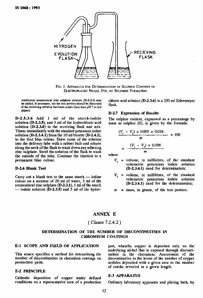
D-2.4.1 Hydrogen Sulphide Evolution Apparatus (Fig. l), comprising :
4 b>
Erlemneyer flask, of capacity 250 ml;
a wash bottle fitting with an exit tube, leading to
4 a receiving flask.
D-2.3 Reagents
During the analysis, use only reagents of recognized analytical grade and only distilled water or water of equivalent purity.
Tbe Erlenmeyer flask can be heated by an eleclric hot-plate.
D-2.4.2 Burette, of capacity 10 ml.
D-2.5 Procedure D-2.3.1 Ammoniacal Zinc Sulphate Solution
Dissolve 50 g of zinc sulpbate (ZnSO, . 7H 0) in 250 ml of $vater, add 250 ml of ammonia so ution, f (rd = 0.9 g/ml) 0.90 g/ml and mix. Transfer the solution to a flask and allow to stand for approximately 24 b; filter it into a polyethylene bottle.
D-2.5.1 Nickel Test Foil
Prepare test sample as specified in D-1.7.1.
D-2.5.2 Test Portion
D-2.3.2 Hexachloroplatinic Acid, 10 gll Solution
Dissolve ‘0.5 g of bexacbloroplatinic acid (H,PtC!,. 6%0) in about 40 ml of water, add 5 ml of bydrochlonc acid solution (D-1.4.1), dilute to 50 ml and mix.
Depending on the expected sulpbur content of the product, weigh to the nearest 0.000 1 g, the amount of the nickel test foil (D-2.5.1) indicated below:
D-2.3.3 Hydrochloric Acid -Htxachloroplatinic Acid Solution
Expected Sulphur Content
percent (m/m)
0.005 to 0.07 0.05 to 0.2
Prepare 500 ml of a solution containing 1 volume of hydrochloric acid (D-1.4.1) and 1 volume of water. Add 2.5 ml of the bexacbloroplatinic acid solution (D-2.3.2) and mix.
D-2.5.3 Determination
D-2.5.3.1 Transfer the test portion (D-2.5.2) to the 250 ml evolution flask [D-2.4.1 (a)] and add 25 ml of water.
D-2.3.4 Standard Potassium Iodate Solution, 0.1 m.
Dry some crystals of potassium iodate (KIO,) at 100% for ,l b. Dissolve 3.570 g of the dried potassium iodate in about 200 ml of water, transfer to a 1 000 ml one-mark volumetric flask, dilute to the mark and mix.
D-2.5.3.2 Add 20 ml of water and 3 ml of the ammoniacal zinc sulpbate solution (D-2.3.1) to the receiving flask (D-2.4.1 c).
D-2.3.4.1 Standardpotassium iodate, standard solution (0.005 m).
D-2.5.3.3 Adjust the hot-plate to maintain the temperature of the water in the evolution flask at SO%.
Transfer 25 ml of the standard volumetric potassium iodate solutiou (D-2.3.4) to a 500 ml one-mark volumetric flask with a pipette, dilute to the mark and mix.
D-2.5.3.4 Add 15 ml of the hydrochloric acid bexacbloroplatinic acid solution (D-2.3.3) to the evolution flask. Quickly assemble the apparatus as shown in the figure and pass a very gentle stream of the nitrogen (D-2.3.7) through the apparatus.
D-2.3.5 Starch-Iodide Solution
Add about 5 ml of water to 1 g of soluble starch with stirring until a paste is formed. Add the paste to 100 ml of boiling water and mix. Cool the solution, add 5 g of potassium iodide (KI) and stir until the potassium iodide is dissolved.
NOTE-Flow of about 30 ml/min is satisfactory. If the sample dissolves rapidly, the flow should be decreased during the time that hydrogen is freely liberated.
D-2.3.6 Dilute Hydrochloric Acid, (1:l) (V/V).
D-2.5.3.5 Continue the heating and flow of nitrogen until the samples is completely dissolved, and for a further 5 min. Detach the gas delivery tube from the evolution bead and remove the receiving flask with the delivery tube.
D-2.3.7 Nitrogen, supplied from cylinder, fitted with valves and pressure regulator.
NOTE - The solution in the receiving flask will remain alkaline throughout the dissolution period if the hot-plate temperature and the nitrogen flow are properly adjusted.
IS 1068 : 1993
Mass of Sample g
1.00 -c 0.02 0.40 2 0.02
11
IS 1068 : 1993
RECIEVING FLASK
FIG. 1 APPARATUS FOR DETERMINATION OF SULPHUR CONTENT OF ELECTROPLATED NICKEL FOIL BY SULPHIDE FORMATION
Addifional ammoniacal zinc sulphate solution (D-2.3.1) may be added, if necessary, but the test portion should be discarded if the receiving solution becomes acidic (less than pH 7 to test paper).
D-2.5.3.6 Add 1 ml of the starch-iodide solution (D-2.3.5), and 5 ml of the hydrochloric acid solution (D-2.3.6) to the receiving flask and mix. Titrate immediately with the standard potassium iodate solution (D-2.3.4.1) from the 10 ml burette (D-2.4.2), to the first blue colour. Draw some of the solution into the delivery tube with a rubber bulb and release along the neck of the flask to wash down any adhering zinc sulphate. Swirl the solution of the flask to wash the outside of the tube. Continue the titration to a permanent blue colour.
D-2.6 Blank Test
Carry out a blank test to the same starch - iodine colour on a mixture of 20 ml of water, 3 ml of the ammoniacal zinc sulphate (D-2.3.1), 1 ml of the starch - iodate solution (D-2.3.5) and 5 ml of the bydro-
DETERMINATION
cbloric acid solution (D-2.3.6) in a 250 ml Erlemneyer flask.
D-2.7 Expression of Results
The sulpbur content, expressed as a percentage by mass as sulpbur (S), is given by the formula:
(VI - I’,) x 0.005 x 0.016 x loo
=
where v, =
v2 =
m =
ANNEX E
(Clause 7.2.4.2)
m
cv, - V,) x 0.008
m
volume, in millilitres, of the standard volumetric potassium iodate solution (D-2.3.4.1) used for determination;
volume, in millilitres, of the standard volumetric potassium iodate solution (D-2.3.4.1) used for the determination;
mass, in grams, of the test portion.
OF TIIE NUMBER OF DISCONTINUITIES IN CHROMIUM
E-l SCOPE AND FIELD OF APPLICATION
This amtex specifies a method for determining the number of discontinuities in chromium coatings on production parts.
E-2 PRINCIPLE
Cathodic deposition of copper under defined conditions on a representative area of a production
COATINGS
part, wbereby copper is deposited only on the underlying nickel that is exposed through disconti- nuities in the chromium. Assessment of the discontinuities in the terms of the number of copper nodules deposited with a given area or the number of cracks revealed in a given length.
E-3 APPARATUS
Ordinary laboratory apparatus and plating bath, by
12

.
JneaJJs of which copper nlay be deposited cathodically on the test piece-.
The bath solution contaiJJs 200 g/l of copper sulphate (CuSO, .5H,O) and 20 g/l of sulphuric acid (H2S04) and shall be maintained at a temperalure of 18O to 24oC throughout the detenlJiJJalion. The cathode current density used is 30A/JJJ*.
E-4 PROCEDURE
E-4.1 Preparation of the Test Piece
Prepare the test piece as follows.
Mask all edges not covered by the chrolniunl coatiJJg with a non-conductivity paint or pressure seJu+itive tape, including the wire used to nlake contact to the cathode bar of the plating bath. Clean by immersion in a hot alkaline cleaner at a temperature not exceeding 65OC until the surface is homogeneously wetted. A gentle scrubbing with a soft brush is helpful. Thoroughly rinse in cold running waler, and then imnlerse for 5 to 10 s in approximalely 5 percent (nr/m) sulphuric acJd solution. In cases where the test is applied several days after chromium deposition, imnlerse the test piece in a solution containing 10 to 20 g of nitric acid per Ii&e for 4 min at approximately
IS 1068 : 1993
65OC before the copper deposition stage, to help reveal the cracks or pores.
E-4.2 Determination
Connect the. test piece and the anode to the current supply before imnlersion. ImnJerse both electrodes in the plating bath (E-3) and deposit copper cathodically on the prepared test piece with a cathode current density 30 A/n?. Use an immersion time of approximately 1 to 5 Jnin at a tenlperalure of lS” to 24OC. The copper will deposit only on the underlaying nickel that is exposed through discontinuities ( pores and cracks ) in the chrontium.
Carefully renlove the test piece, riJlse in cold and then in hot water and air-dry (do not use conlpressed air). The test piece shall not be wiped where pores or cracks are to be counted.
!%nlate the number of discontinuides in the chromiunl by counting the copper J~odules deposited within a known area or the number of cracks in a known length of the test piece. These determinations Jnay be carried out using either a nletallurgical microscope fitted with a calibrated reticle in the eyepiece, or from microphotographs taken of a representative field of Lhe test piece.
ANNEX F
( Clause 7.4 )
MODIFIED FERROXYL TEST
F-l GENERAL
This method reveals disconlinuities such as pores, in electroplated nickel on iron or steel.
F-2 TEST SOLUTION
F-2.1 Solution A is prepared by dissolving 50 g of white gelatine and 50 g of sodium chloride in one litre of wann (45OC) distilled waler.
F-2.2 Solution B is prepared by dissolvirlg 50 g of sodium chloride and 1 g of non-ionic welling agent in one litre of distilled water.
F-2.3 Soluiion C is prepared by dissolviJJg 10 g of potassium ferricyaJJide in one litrc of distilled water.
V-3 PROCEDURE
Filter paper strips are imnierscd in solution A, which is kept sufficiently wart11 to keep the gelatine dissolved, and then allowed to dry. Just before use, immerse the dry filter paper strips in solutioJJ B just long enough to thoroughly wet all of the filler paper. Firndy press the filter paper against the thoroughly rlcaned and degreased electroplated nickel surface lo be
13
tested. Allow 10 min contact time for the test period ( see Note ). If the filler paper should become dry during the test, moisten again with solution B. Remove the papers at the end of the contact period, and place at once into solution C. Sharply defined blue markings will appear on the papers indicating basis metal corrosion or porosity.
NOIE - l%lhis lest is slightly corrosive IO nickel particularly if the test period is extended appreciably (3 minutes or more) beyond the 10 minutes period. The test is very sensitive IO the superficial pressure of iron that is, blue spots can occur on an elecrrodeposifed nickel surface that has been in sufficient contact with a piece of iron to leave a trace of the irons on Ihe nickel surface.
F-4 REPORT
The following information shall bc included in the report.
The area of surface tested.
The total JlUmber aJJd diaJneter of all spols on the filter paper used for surface area tested.
The highest JJumber of spots visible within a square area as defined aad speritied by the pl!rcti;!%:r.

IS 1068 : 1993
DETERMINATION
G-l PRINCIPLE
ANNEX G
( Clause 9.1.1 )
OF CHROMIUM THICRNESS BY COULOMETRIC METHOD
The method is based on the measurement of the quantity of electricity required to dissolve anodicslly an electrodeposited coating over a known area.
G-2 TEST SOLUTION
Dilute 62 ml of orthophosphoric acid (sp-gr 1.75) to 1 litre.
G-3 PROCEDURE
G-3.1 Clean the area to be tested with a cloth, wetted with an organic solvent for grease removal, if necessary.
G-3.2 Press an electrolytic cell, fitted with a flexible sealing ring an incorporating an annular cathode on the coating so that a circle of known area is exposed to the test solution. Introduce ihe test solution into the cell; insert the stirrer if appropriate to the instrument used and the. thickness of .the deposit.
G-3.3 Make the electrical connections with the specimen being anodic. Continue electrolysis until dissolution of the chromium coating is complete, as indicated by sudden change in anode potential, and record the quantity of electricity consumed.
G-3.4 Examine the specimen ana ensure that chromium removal is complete over the area of the cell.
G-4 CALCULATION
Calculate the thickness of the chromium coating from the following formula assuming 100 percent current efficiency:
Thickness, pm = Q
- x 12.6 A
where
Q k quantity of electricity consumed (columbs), and
A = area tested (mm’).
ANNEX H
( Clause 9.2 )
FILE TEST FOR ADHESION
H-l The file test shall be carried out as follows: from the basis metal to the coating at an angle of approximately 45O to the coated surface.
H-l.1 Saw piece off a plated article, hold it in a H-l.2 There shall be no separation between the vice and apply a coarse file to the outer edge in such coating and the basis metal nor between the layers a manner as to raise the deposit. File with direction of a multiple coating.
ANNEX J
( Clause 9.2 )
QUENCHING TEST FOR ADHESION
J-l PROCEDURE
J-l.1 Heat a plated article for a sufficient time in an oven for it to reach the temperature shown in Table 8 with a tolerance of +lO°C. Then quench the part in water at room temperature. The appearance of blisters or peeling shall give evidence of inadequate adhesion.
Table 8 Recommended Quenching Test. Temperature
( &use J-l.1 )
subsrnte Temperaturq Oc
S&l 250 Zinc alloys 150 Copper and copper alloys 250 Aluminium and aluminium alloy 220
14

Bureau of Indian Standards
BIS is a statutory institution established under the Bureau oflndian Standards Act, 1986 to promote harmonious development of the activities of standardization, marking and quality certification of goods and attending to connected matters in the country.
Copyright
BIS has the copyright of all its publications. No part of these publications may be reproduced in any form without the prior permission in writing of BIS. This does not preclude the free use, in the course of implementing the standard, of necessary details, such as symbols and sizes, type or grade designations. Enquiries relating to copyright be addressed to the Director (Publications), BIS.
Review of Indian Standards
Amendments are issued to standards as the need arises on the basis of comments. Standards are also reviewed periodically; a standard along with amendments is reaffirmed when such review indicates that. no changes are needed; if the review indicates that changes are needed, it is taken up for revision. Users of Indian Standards should ascertain that they are in possession of the latest amendments or edition by referring to the latest issue of ‘BIS Handbook’ and ‘Standaids : Monthly Additions’.
This Indian Standard has been developed from Dot : No. MTD 20 ( 3734 ).
Amendments Issued Since Publication
Amend No. Date of Issue Text Affected
BUREAU OF INDIAN STANDARDS
Headquarters:
Manak Bhavan, 9 Bahadur Shah Zafar Marg, New Delhi 110002 Telephones : 323 01 31, 323 94 02, 323 33 75
Telegrams: Manaksanstha ( Common to
all offices )
Regional Offices: Telephone
Centr:al : Manak Bhavan, 9 Bahadur Shah Zafar Marg 323 76 17 NEW DELHI 110002 323 3841
Eastern : l/14 C. I. T. Scheme VII M, V. I. P. Road, Maniktola 337 84 99,337 85 61 CALCUTTA 700054 337 86 26, 337 86 62
Northern : SC0 335-336, Sector 34-A, CHANDIGARH 160022 I 60 38 43 60 20 25
Southern : C. I. T. Campus, IV Cross Road, CHENNAI 600113 23502 16,2350442 235 15 19,235 23 15
Western : Manakalaya, E9 MIDC, Marol, Andheri (East) MUMBAI 400093
8329295,8327858 8?2 78 91,832 78 92
Branches : AHMADABAD. BANGALORE. BHOPAL. BHUBANESHWAR. COIMBATORE. FARIDABAD. GHAZIABAD. GUWAHATI. HYDERABAD. JAIPUR. KANPUR. LUCKNOW. NAGPUR. PATNA. PUNE. THIRUVANANTHAPURAM.
Printed at New India Printing Press, Khwjs, India
.“.-
. . r. _

AMENDMENT NO. 1 NOVEMBER 1999 TO
IS 1068 : 1993 ELECTROPLATED COATINGS OF NICKEL PLUS CHROMIUM AND COPPER PLUS NICKEL PLUS CHROMIUM - SPECIFICATION
( Third Revision)
(Page 6, clause 9.1.4 ) - Delete.
(MTD20)
Reprography Unit, BE, New Delhi, India
‘_
.