irrinet-ace assembly manual - weebly
TRANSCRIPT

Irrinet-ACE Assembly Manual
Wiring Harnesses, Components, and Mounting
Brody Gibbs
11/21/2012

Table of Contents iii
Table of Contents Table of Contents ........................................................................................................................... iii
Introduction ..................................................................................................................................... v
Chapter 1: Wiring Harnesses .......................................................................................................... 1
What are Wiring Harnesses? ....................................................................................................... 3
Building Wire Combs ............................................................................................................. 4
Building the Output Wiring Harness ...................................................................................... 6
Building Input Wiring Harnesses............................................................................................ 8
Chapter 2: Components................................................................................................................. 11
What are Components? ............................................................................................................. 13
Wiring the 110 Components ................................................................................................. 14
Mounting the Wired 110 Components .................................................................................. 18
Building the Input Common Terminal Block ....................................................................... 20
Chapter 3: Backplates ................................................................................................................... 23
What are Backplates? ................................................................................................................ 25
Assembling the ACE-side Backplate .................................................................................... 26
Assembling the Surge Card-side Backplate .......................................................................... 32
Chapter 4: The Completed Irrinet-ACE ........................................................................................ 35
What now?................................................................................................................................. 37
Connecting the ACE-side and Surge Card-side Backplates ................................................. 38
Wiring Diagrams ........................................................................................................................... 43
Output Wiring Diagram ............................................................................................................ 43
Input Wiring Diagram ............................................................................................................... 44
Index ............................................................................................................................................. 45

Introduction v
Introduction
The Irrinet-ACE is a complicated irrigation controller used by cities and school districts to
manage the water supply and use water most effectively. This manual will show how to build an
ACE from the ground up using the available supplies and components. A basic understanding of
the following are required to successfully build an ACE using this manual:
Tool/Hardware names and uses
Wiring diagrams
Soldering wire
Terms associated with ACE components
This manual also provides notes on how to make an ACE building/repair project quicker and
easier. Confusing steps are accompanied by a photograph or graphic showing an ACE actually
being built.
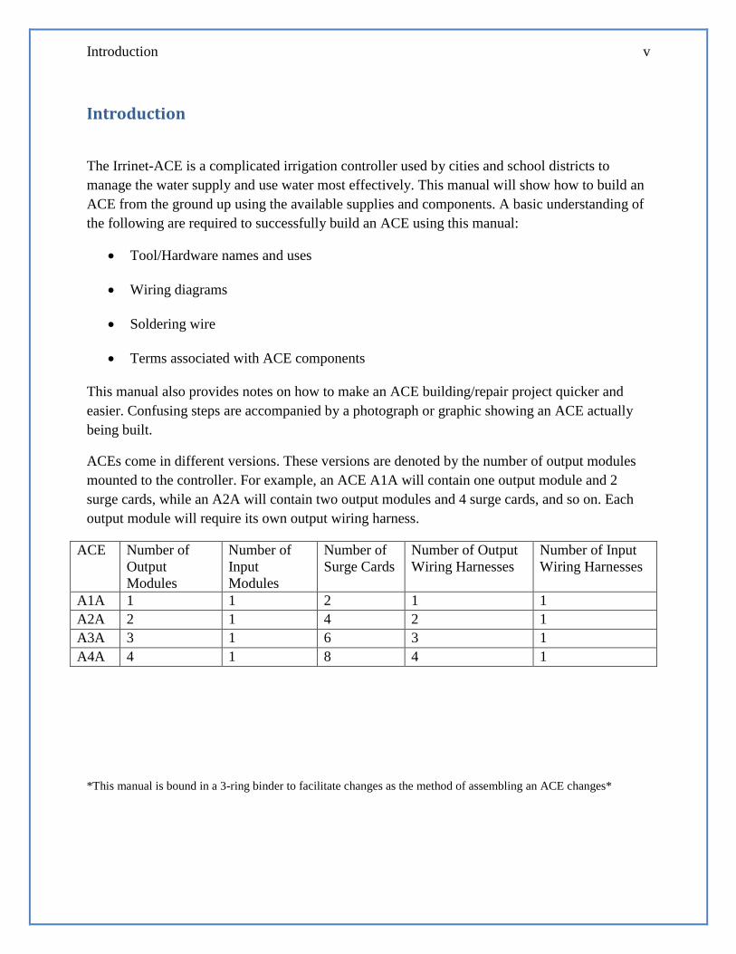
ACEs come in different versions. These versions are denoted by the number of output modules
mounted to the controller. For example, an ACE A1A will contain one output module and 2
surge cards, while an A2A will contain two output modules and 4 surge cards, and so on. Each
output module will require its own output wiring harness.
ACE Number of
Output
Modules
Number of
Input
Modules
Number of
Surge Cards
Number of Output
Wiring Harnesses
Number of Input
Wiring Harnesses
A1A 1 1 2 1 1
A2A 2 1 4 2 1
A3A 3 1 6 3 1
A4A 4 1 8 4 1
*This manual is bound in a 3-ring binder to facilitate changes as the method of assembling an ACE changes*


Figure 1: A completed wiring harness with zip-ties.
Chapter 1: Wiring Harnesses


Chapter 1: Wiring Harnesses 3
What are Wiring Harnesses?
Wiring harnesses are used by every Irrinet controller to connect the controller’s logic board to its
surge cards. Wiring harnesses come in many different sizes and configurations, each with its own
purpose. Output wiring harnesses on an ACE connect the controller’s output modules to its surge
cards, while Input modules connect the controller’s input modules to the surge cards. The only
differences between ACE output wiring harnesses are their length and the color of the DO Wet
wire used. A1A wiring harnesses will be shorter than A2A wiring harnesses, and so on. The
wiring harness jig provides a guide on how long each wire should be. On the wiring jig, an A1A
wiring harness will connect a mock output module to mock surge cards with wires. A1A wiring
harnesses will use positions M1#1 and M1#2 for the surge card side of the wiring harness, and
A2A wiring harnesses will use positions M2#1 and M2#2. This pattern will continue to A3A
harnesses, and repeat for A4A through A6A

4 Irrinet-ACE Assembly Manual
Building Wire Combs
CAUTION
Soldering irons are capable of operating at 850°F. Do not touch any metal pieces of a soldering
iron, wet (and hot) solder, or recently soldered wires. Always allow ample time for wires and
solder to cool down before touching them.
1. Cut 15 2” pieces of white wire and strip ½” of insulation off of both sides.
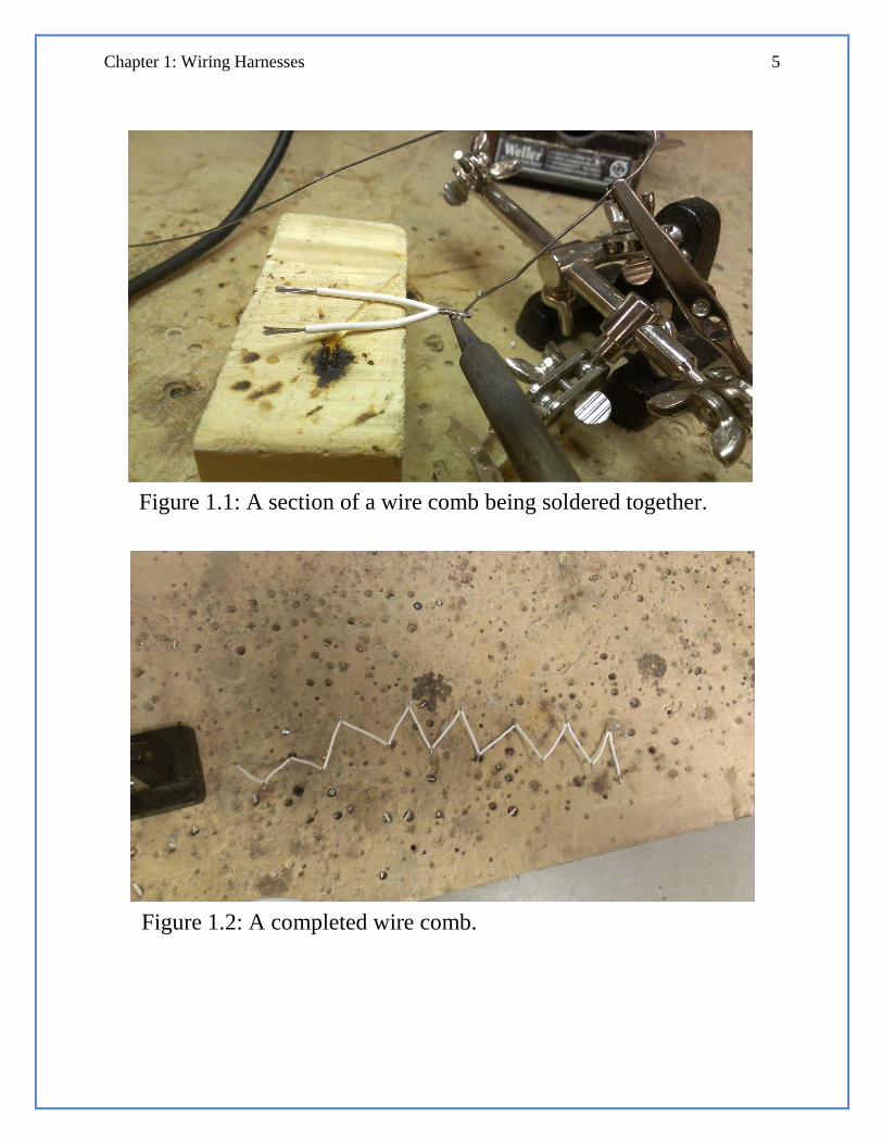
2. Twist two pieces of exposed wire together, and solder them to hold them together.
(Figure 1.1)
3. Join all 15 pieces of white wire with solder. The resulting shape will be a zigzag,
resembling a hair comb. (Figure 1.2)
4. Set the finished wire comb aside.
Note: After building a comb, clip any excess solder off of the comb, as well as any
excess wire. This will make it easier to attach combs to terminals.
Chapter 1: Wiring Harnesses 5
Figure 1.1: A section of a wire comb being soldered together.
Figure 1.2: A completed wire comb.
6 Irrinet-ACE Assembly Manual
Building the Output Wiring Harness
Note: Use the ACE wiring harness jig to build all ACE wiring harnesses. Wiring
diagrams for both input and output wiring harnesses are provided on page 43 and 44.
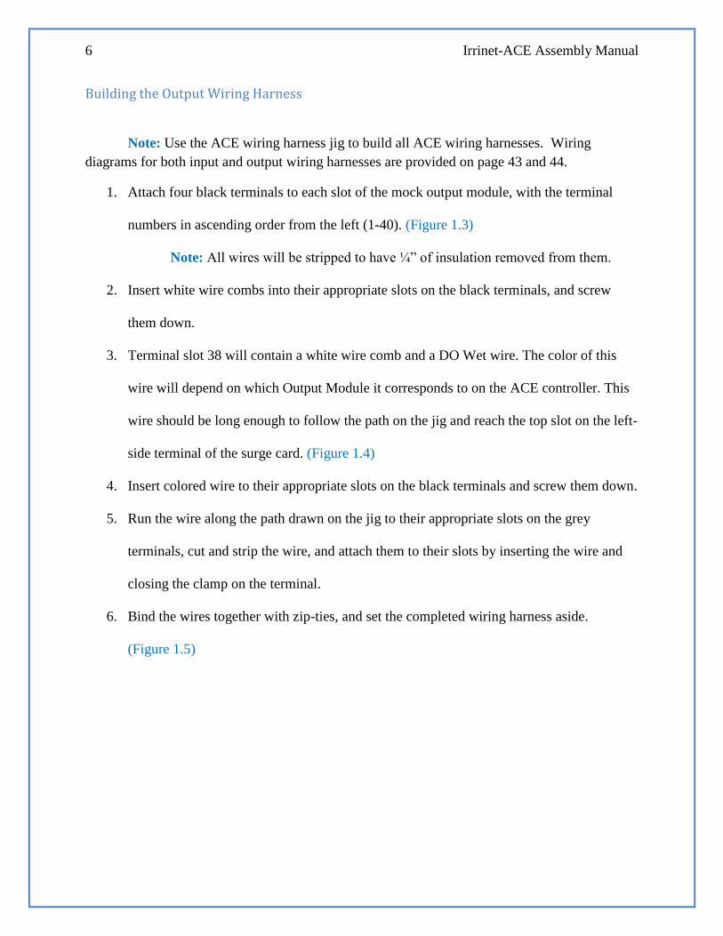
1. Attach four black terminals to each slot of the mock output module, with the terminal
numbers in ascending order from the left (1-40). (Figure 1.3)
Note: All wires will be stripped to have ¼” of insulation removed from them.
2. Insert white wire combs into their appropriate slots on the black terminals, and screw
them down.
3. Terminal slot 38 will contain a white wire comb and a DO Wet wire. The color of this
wire will depend on which Output Module it corresponds to on the ACE controller. This
wire should be long enough to follow the path on the jig and reach the top slot on the left-
side terminal of the surge card. (Figure 1.4)
4. Insert colored wire to their appropriate slots on the black terminals and screw them down.
5. Run the wire along the path drawn on the jig to their appropriate slots on the grey
terminals, cut and strip the wire, and attach them to their slots by inserting the wire and
closing the clamp on the terminal.
6. Bind the wires together with zip-ties, and set the completed wiring harness aside.
(Figure 1.5)

Chapter 1: Wiring Harnesses 7
Figure 1.3: Mock output module with black terminals in
ascending order.
Figure 1.2: ACE wiring harness jig. The red arrow points to the grey terminal that the
DO Wet wire must reach, following the path. The pathway is not shown, but is visible
on the jig. The blue arrow points to where grey terminals attach to the surge card.
Figure 1.5: A Completed Output Wiring Harness (A1A).

8 Irrinet-ACE Assembly Manual
Building Input Wiring Harnesses
1. Attach two black terminals to the mock input module with the terminal numbers in
ascending order from the left (1-20). If the machine being built is an A1A or A2A, it will
only need 1 black terminal block (1-10).
Note: All wires will be stripped to have ¼” of insulation removed from them.
2. Insert colored wires into their appropriate slots on the black terminals and screw them
down.
3. Run the wire along the path drawn on the jig to their appropriate slots on the grey
terminals, cut the wire, but do not attach them to the grey terminals. Instead, leave the
loose ends unattached and do not strip the insulation off of them.
Note: Each terminal will get two input wires. The first pair of wires will need to
be able to reach “module 1” on the jig, the second, third, sixth, and seventh pair
should reach “module 2,” and the fourth, fifth, and eighth pair should reach
“module 3.” (Figure 1.6)
4. Terminal slots 9 and 19 will contain a white wire (the white wire in slot 9 will be jumped
to slot 19 if a second black terminal block is used). Run this wire along the path on the jig
all the way back to the mock output module, and cut it.
5. Bind the wires together with zip-ties, and set the completed wiring harness aside.
Note: Binding pairs of input wire together with zip-ties makes it easier to
remember which wire goes where when connecting them to the surge cards later.
(Figure 1.7)

Chapter 1: Wiring Harnesses 9
Figure 1.6: An ACE wiring harness jig. The red, blue, and green
wires point to modules 1, 2, and 3, respectively.
Figure 1.7: Pairs of input wire zip-tied together. Wires that are
zip-tied together go to the same surge card.

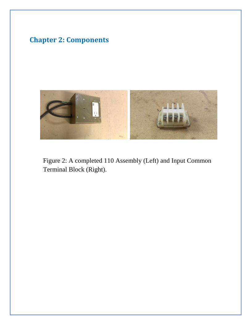
Figure 2: A completed 110 Assembly (Left) and Input Common
Terminal Block (Right).
Chapter 2: Components


Chapter 2: Components 13
What are Components?
The 110 Assembly allows the machine to be powered through an external energy source. This
component takes little time to assemble but is very confusing. It is important to try to hold every
wire still when tightening any screws because they come out of their ports easily. This is
expedited by the use of stationary clamps (if available) to hold each wire in place while
tightening them down. The Input Common Terminal Block is fairly simple to build; however,
some force may be required to attach the end anchors to the mounting bracket. Often times it is
easier to remove a small portion of the end teeth on the side of the mounting bracket and attach
the end anchors than force the end anchors on.

14 Irrinet-ACE Assembly Manual
Wiring the 110 Components
1. Cut 15” of power cable, and remove 2” of insulation from it on both sides to
expose the internal wires. This will be the Power In cable.
2. Strip ½” of insulation off the black and white wires on one side of the Power In
cable. Strip ¼” of insulation off the green wire on the same side, and attach a blue
ring connector to it.
3. Cut 22” of power cable and remove 2” of insulation from it on one side, and 3”
from the other to expose the internal wires. This will be the Power Out Cable.
4. Strip ½” of insulation off the black and white wires on the 2” side of the Power
Out cable. Strip ¼” of insulation off the green wire, and attach a blue ring
connector to it.
5. Strip ¼” of insulation off all the wires of a 110 Surge Protector, and attach blue
fork connectors to the black and white wires. Attach a blue ring connector to the
green wire.

Chapter 2: Components 15
Figure 2.1: From top to bottom: 110 Surge Protector, Power Out
cable, and Power In cable, all with attached connectors.

16 Irrinet-ACE Assembly Manual
6. Remove the wire covers from the black wires on a GFCI switch.
7. Find and completely tighten the green screw on the GFCI switch. (Figure 2.2)
8. Lay the GFCI switch so that its two black wires are on the left.
9. Insert the bottommost black wire from the GFCI switch into the hole on the
bottom left of the GFCI switch.
10. Insert the black wire from the Power In cable into the hole on the bottom right of
the GFCI switch.
11. Attach the black wire from the 110 Surge Protector to the screw on the bottom of
the GFCI switch, and tighten it. This will secure all 3 black wires. (Figure 2.3)
12. Twist the leftover black wire from the GFCI switch and the black wire from the
Power Out cable together, and secure them with a wire nut.
13. Insert the white wire from the Power Out cable into the hole on the top left of the
GFCI switch.
14. Insert the white wire from the Power In cable into the hole on the top right of the
GFCI switch.
15. Attach the white wire from the 110 Surge Protector to the screw on the top of the
GFCI switch, and tighten it. This will secure all 3 white wires. (Figure 2.4)
Chapter 2: Components 17
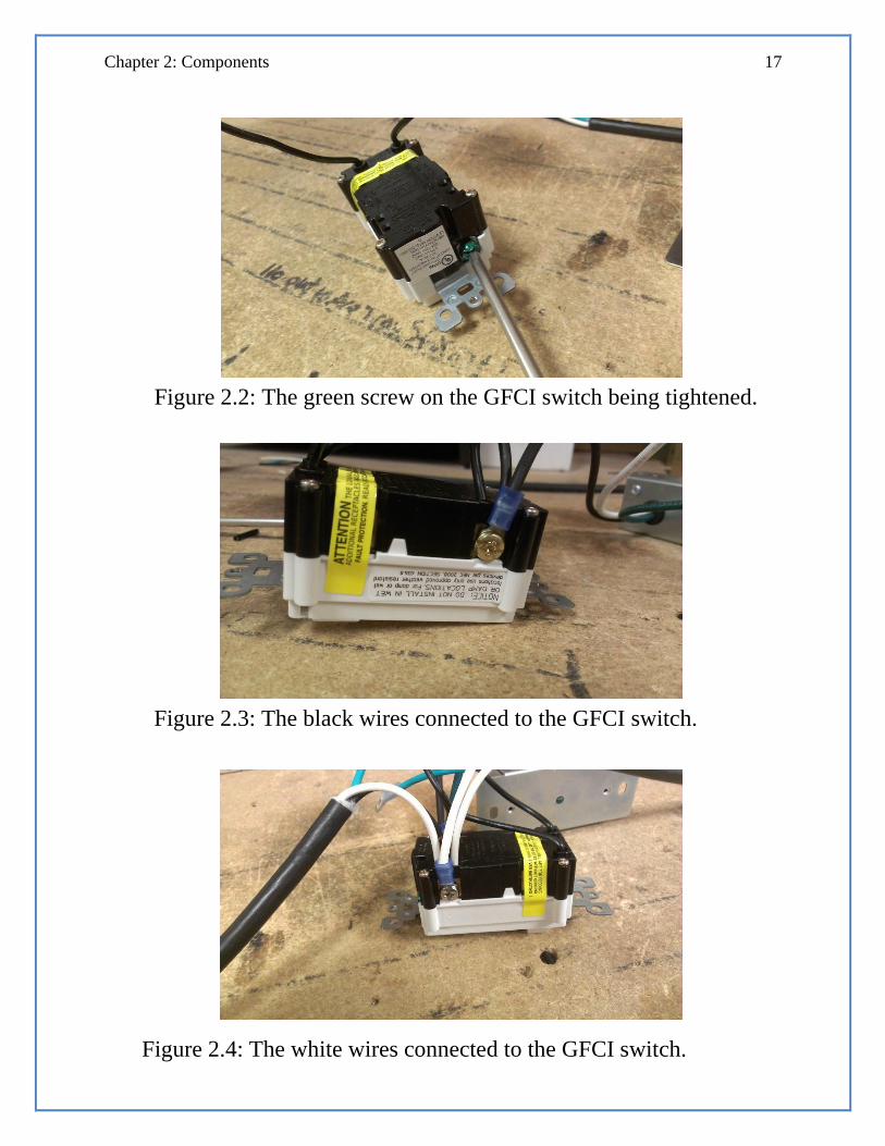
Figure 2.2: The green screw on the GFCI switch being tightened.
Figure 2.3: The black wires connected to the GFCI switch.
Figure 2.4: The white wires connected to the GFCI switch.

18 Irrinet-ACE Assembly Manual
Mounting the Wired 110 Components
1. Place the wired 110 Assembly in a 110 Assembly top, with the GFCI switch
protruding from the hole on the other side of the top.
Note: With the front of the 110 Assembly facing you, the GFCI switch
should be on the right with its outlet on the bottom, and the green 110
Surge Protector light should be seen through a small hole in the 110
Assembly top. (Figure 2.5)
2. Secure all green wires (ground) to the screws protruding from the inside of the
110 top with aircraft nuts. The Power Out ground should be at the top of the 110
Assembly, the Power In ground should be at the bottom, and the 110 Surge
Protector ground should be on either side of the 110 Surge Protector.
3. Strip ¼” of insulation off all 3 wires on the unused side of the Power In cable.
This side of the cable will not be used during assembly.
4. Strip ½” of insulation off the black and white wires on the unused 3” side of the
Power Out cable. Strip ¼” of insulation off the green wire, and attach a blue fork
connector to it.
5. Set the completed 110 Assembly aside. (Figure 2.6)

Chapter 2: Components 19
Figure 2.5: Completed 110 Assembly from the front. The Power
In cable is protruding from the bottom hole and the Power Out
cable is protruding from the top.
Figure 2.6: Completed 110 Assembly from the back. The GFCI
switch can be seen on the left, and the 110 surge protector on the
right. The ground cables are secured by an aircraft nut.
20 Irrinet-ACE Assembly Manual
Building the Input Common Terminal Block
1. Break off 3” of an aluminum mounting bracket.
2. Mount 4 terminal blocks onto the mounting bracket by inserting one side of
the mounting bracket into the clip on one side of the terminal block.
(Figure 2.7)
3. Use a flathead screwdriver to pry the terminal block’s clip on the opposite
side open, and insert the other side of the mounting bracket into it.
4. Unscrew both screws on a terminal block end anchor and insert the mounting
bracket underneath the white piece of the end anchor, with the gold piece
below the mounting bracket. Some force may be required to fully insert the
mounting bracket into the end anchor. (Figure 2.8)
Note: Use a pair of vise grips to break off about half of one “tooth” on
each end of the mounting bracket. This will make it easier to insert the
mounting bracket into the end anchor.
5. Tighten the screws on the end anchor back down to secure it to the mounting
bracket.
6. Repeat steps #4 and #5 on the other side of the mounting bracket.
7. Set the completed Input Common Terminal Block aside.
Chapter 2: Components 21
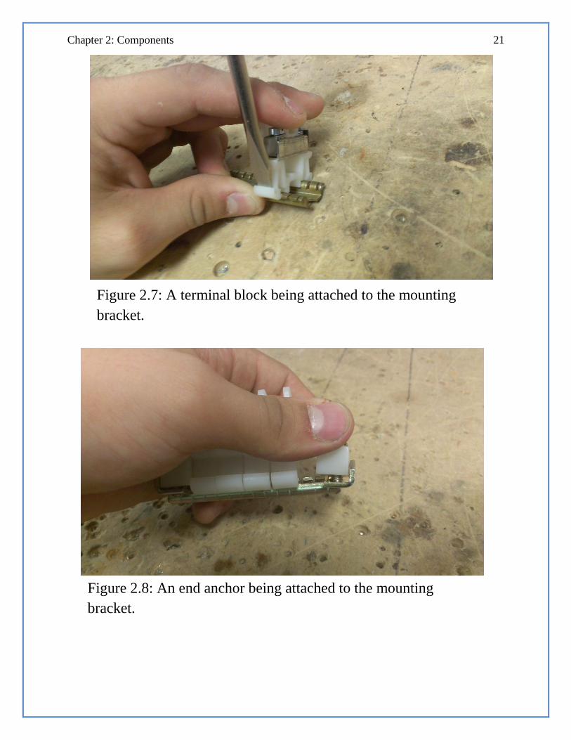
Figure 2.7: A terminal block being attached to the mounting
bracket.
Figure 2.8: An end anchor being attached to the mounting
bracket.


Figure 3: A blank backplate (Left) and a backplate with mounted
surge cards (Right).
Chapter 3: Backplates


Chapter 3: Backplates 25
What are Backplates?
A backplate is where all of the previously assembled components are mounted. Each component
should be mounted in a place where all of its wires are easily accessible during installation. Take
care not to drop the backplates when mounting them to the enclosure. Upon completion, the
backplates will be connected through their enclosure.

26 Irrinet-ACE Assembly Manual
Assembling the ACE-side Backplate
1. Insert one 2 ¼” bolt with a lock-washer and flat-washer into each of the ACE
mounting holes on the backplate.
2. Screw two nuts onto the other side of each of the four bolts and tighten them
down.
3. Place the ACE controller onto the four bolts and tighten a flat-washer, lock-
washer, and nut onto each bolt.
4. Attach a transformer to its appropriate position with a metal screw on the
backplate. Only attach the top mounting bracket.
5. Cut the bottom red wire on the transformer to be approximately 3” long, strip it to
expose ¼” of wire, and attach a blue ring connector to it.
6. Use a metal screw to mount the bottom mounting bracket and the recently
attached ring connector to the backplate.
7. Attach a 110 assembly bottom to its appropriate position on the backplate using
metal screws.
8. Thread 110 power-in and power-out cables through their appropriate holes on the
110 bottom.
9. Attach a fully assembled 110 assembly to its bottom on the backplate with
machine screws. (Figure 3.1)

Chapter 3: Backplates 27
Figure 3.1: The ACE-side backplate with all of the components.

28 Irrinet-ACE Assembly Manual
10. Cut the black and white wires from the transformer to reach the 110 Junction Box
on the controller.
11. Twist the black and white wires to their corresponding wires from the 110 power-
out cable and screw them into the 110 Junction Box on the ACE controller.
Note: Threading these wires underneath the battery cables makes
installation much easier and makes the whole assembly look less cluttered.
12. Attach the green wire from the 110 power-out cable to the controller’s ground-
plate. (Figure 3.2)
13. Place a cover over the 110 Junction Box and secure it with supplied screws
Note: Make sure that all four of the wires are on the top side of the cover’s
screw post, or the cover will not screw down all the way.
14. Insert the appropriate amount of output modules (labeled “16 DO”) into the
controller (A1A will get one module, A2A will get two, and so on). If the amount
of output modules called for is more than the amount shipped with the device, a
red connection cover must be removed from inside the controller with a set of
pliers before inserting it into the controller. (Figure 3.3)
Note: Make sure that the single input module (labeled “16 DO/DI”) that is
shipped with the ACE is furthest to the right. If it is not, exchange it with
the rightmost output module before connecting any wiring harnesses.

Chapter 3: Backplates 29
Figure 3.2: The 110 Junction Box and ground cable. Notice that
the black and white wires are above the screw post.
Figure 3.3: A red connector cover next to an uncovered
connector.
30 Irrinet-ACE Assembly Manual
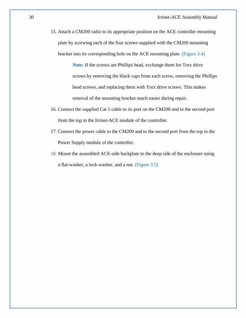
15. Attach a CM200 radio to its appropriate position on the ACE controller mounting
plate by screwing each of the four screws supplied with the CM200 mounting
bracket into its corresponding hole on the ACE mounting plate. (Figure 3.4)
Note: If the screws are Phillips head, exchange them for Torx drive
screws by removing the black caps from each screw, removing the Phillips
head screws, and replacing them with Torx drive screws. This makes
removal of the mounting bracket much easier during repair.
16. Connect the supplied Cat 5 cable to its port on the CM200 and to the second port
from the top in the Irrinet-ACE module of the controller.
17. Connect the power cable to the CM200 and to the second port from the top in the
Power Supply module of the controller.
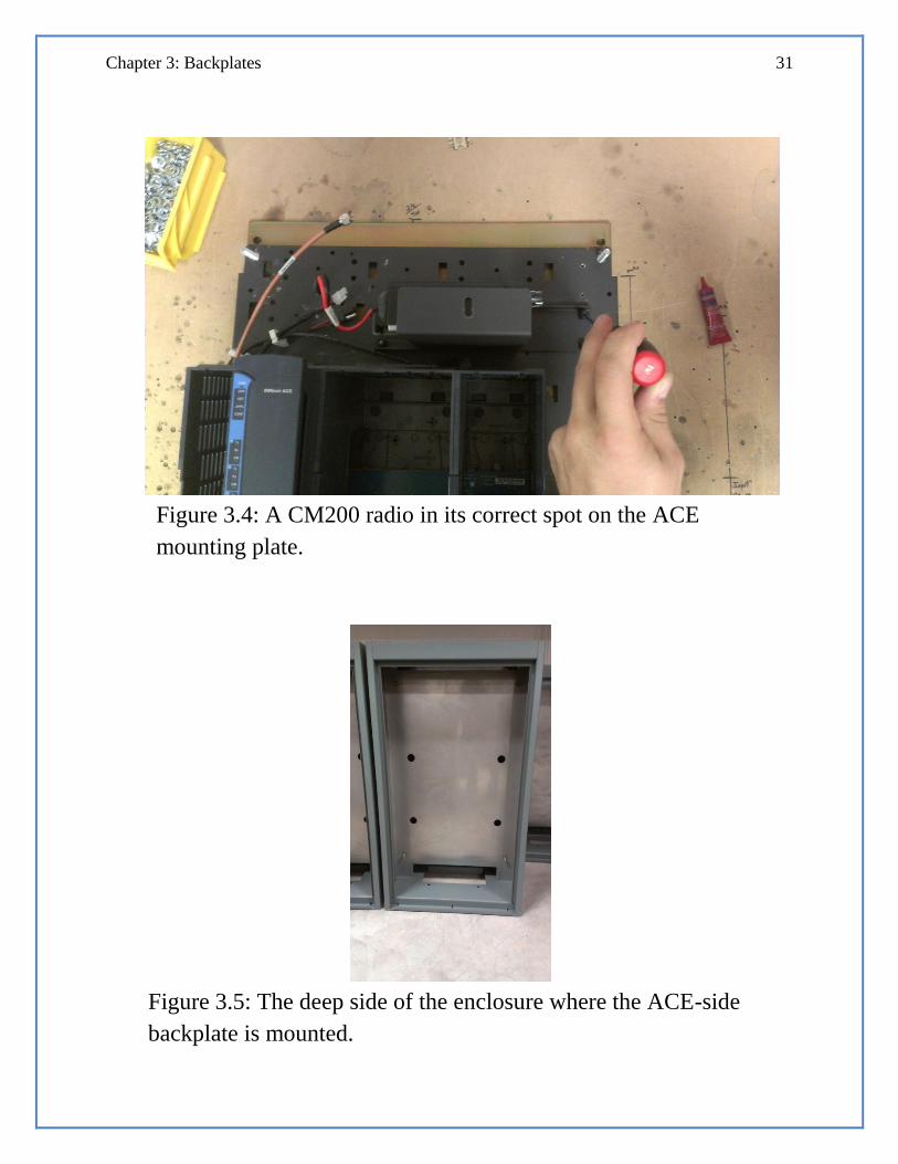
18. Mount the assembled ACE-side backplate to the deep side of the enclosure using
a flat-washer, a lock-washer, and a nut. (Figure 3.5)
Chapter 3: Backplates 31
Figure 3.4: A CM200 radio in its correct spot on the ACE
mounting plate.
Figure 3.5: The deep side of the enclosure where the ACE-side
backplate is mounted.
32 Irrinet-ACE Assembly Manual
Assembling the Surge Card-side Backplate
1. Insert four ½” bolts per surge card into their appropriate holes on the backplate,
each with a lock-washer, and secure each bolt with a standoff nut. Each bolt
should go into the rightmost set of vertically paired holes on the backplate.
(Figure 3.6)
2. Secure the left side of the 8-station surge cards to the standoff nuts with a ½” bolt
Note: Do not tighten the bolts all the way down when securing the surge
cards. Doing so will make installing the wiring harnesses much more
difficult
3. Apply labels to the backplate, with each label lining up with its respective output
terminal on the surge card.
4. Attach the Input Common Terminal Block to the backplate by removing the four
terminal blocks from the assembly, securing the mounting bracket to the
backplate with metal screws, and replacing the terminal blocks.
Note: The holes in the mounting bracket almost never match up to the
holes on the backplate. If the holes do not match up evenly, drill a new
hole using a metal screw.
5. Mount the Surge Card-side backplate to the shallow side of the enclosure using a
flat-washer, lock-washer, and nut.

Chapter 3: Backplates 33
Figure 3.6: A standoff nut being screwed onto a bolt. Mounted
surge cards can be seen on the left.
Figure 3.7: A completed surge card-side backplate with the Input
Common Terminal Block and labels shown.

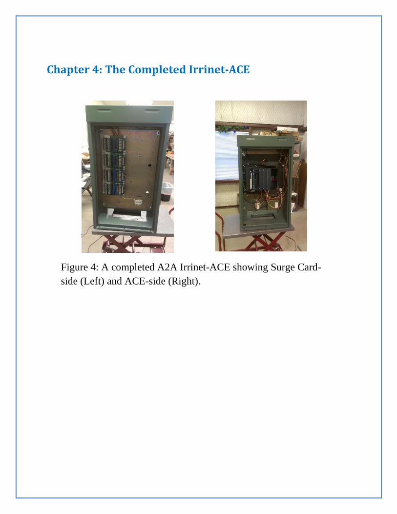
Figure 4: A completed A2A Irrinet-ACE showing Surge Card-
side (Left) and ACE-side (Right).
Chapter 4: The Completed Irrinet-ACE


Chapter 4: Completing the Irrinet-ACE 37
What now?
Once all of the components have been attached to backplates, they must be connected through
the gaps and holes in the enclosure. This process will allow the controller to communicate with
the surge cards and in turn communicate with an irrigation system. Connecting the two
backplates is fairly simple, but the lack of space inside the enclosure makes the process
cumbersome. It is important to thread the wiring harnesses behind the surge cards in order to
keep the space neat looking and accessible. When the entire machine is assembled, it will be
programmed to the customer’s specifications and then shipped out of the shop

38 Irrinet-ACE Assembly Manual
Connecting the ACE-side and Surge Card-side Backplates
1. Connect the black terminals of an output wiring harness to the first output module
on the controller, and pass the grey terminals through the gap near the top of the
enclosure to the other side.
2. Thread the grey terminals and their trailing wires behind the surge cards, and
connect them to the right side of their respective surge cards. (Figure 4.1)
Note: Each wiring harness has two grey terminals, each corresponding to
a single surge card. The terminal that is connected to the shorter wires will
connect to the topmost surge card, and the terminal connected to the
longer wires will connect to the surge card that is second from the top.
3. Attach the loose DO Wet wires to the top slot of the terminal on the left side of
the top surge card.
4. Repeat the preceding three steps for each output module on the ACE and its
corresponding two surge cards.
5. Thread the wires behind the surge cards, and attach each loose wire from an input
wiring harness to its appropriate place on the grey terminals already attached to a
surge card.

Chapter 4: Completing the Irrinet-ACE 39
Figure 4.1: A connected wiring harness. Notice that the wires are
hidden behind the surge cards, and the brown DO Wet wire is
connected to the top port on the left terminal.

40 Irrinet-ACE Assembly Manual
6. Attach the white wire from the input wiring harness to the first terminal block on
the Input Common Terminal Block, and arc a 2” white jumper wire from the first
terminal block on the left to each subsequent block on the assembly. Tighten each
of the top screws to secure the wire
7. Pass the black terminals through the gap near the top of the enclosure to the other
side, and attach them the input module on the ACE controller. (Figure 4.2)
8. Pass the loose red wire from the transformer through the rightmost large hole in
the backplate to the other side of the enclosure.
9. Attach the red wire from the transformer to the top position on the grey terminal
of the bottommost surge card (labeled 24 VAC), and us a red wire to jump to each
24 VAC position on every grey terminal on the right side of the surge cards.
10. Set the completed Irrinet-ACE aside for programming, boxing, and shipping.

Chapter 4: Completing the Irrinet-ACE 41
Figure 4.2: An A3A Input wiring harness connected to the input
module. Notice the white wire (9) is not jumped to 19. Since the
second half of the input module is not used, the white wire runs
from 9 directly to the Input Common Terminal Block, instead of
jumping to 19 first.

Wiring Diagrams 43
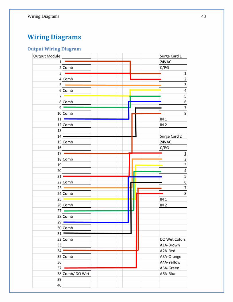
Output Module Surge Card 1
1 24VAC
2 Comb C/PG
3 1
4 Comb 2
5 3
6 Comb 4
7 5
8 Comb 6
9 7
10 Comb 8
11 IN 1
12 Comb IN 2
13
14 Surge Card 2
15 Comb 24VAC
16 C/PG
17 1
18 Comb 2
19 3
20 4
21 5
22 Comb 6
23 7
24 Comb 8
25 IN 1
26 Comb IN 2
27
28 Comb
29
30 Comb
31
32 Comb DO Wet Colors
33 A1A-Brown
34 A2A-Red
35 Comb A3A-Orange
36 A4A-Yellow
37 A5A-Green
38 Comb/ DO Wet A6A-Blue
39
40
Wiring Diagrams
Output Wiring Diagram
44 Irrinet-ACE Assembly Manual
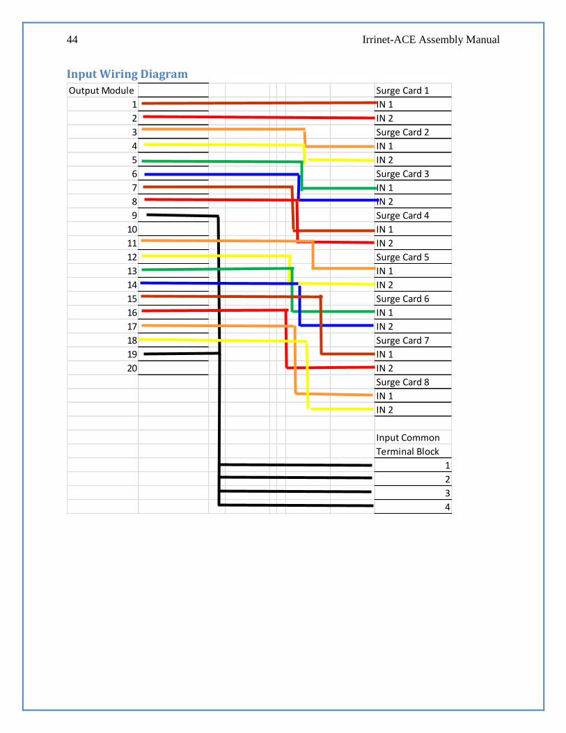
Input Wiring Diagram
Output Module Surge Card 1
1 IN 1
2 IN 2
3 Surge Card 2
4 IN 1
5 IN 2
6 Surge Card 3
7 IN 1
8 IN 2
9 Surge Card 4
10 IN 1
11 IN 2
12 Surge Card 5
13 IN 1
14 IN 2
15 Surge Card 6
16 IN 1
17 IN 2
18 Surge Card 7
19 IN 1
20 IN 2
Surge Card 8
IN 1
IN 2
Input Common
Terminal Block
1
2
3
4
Index 45
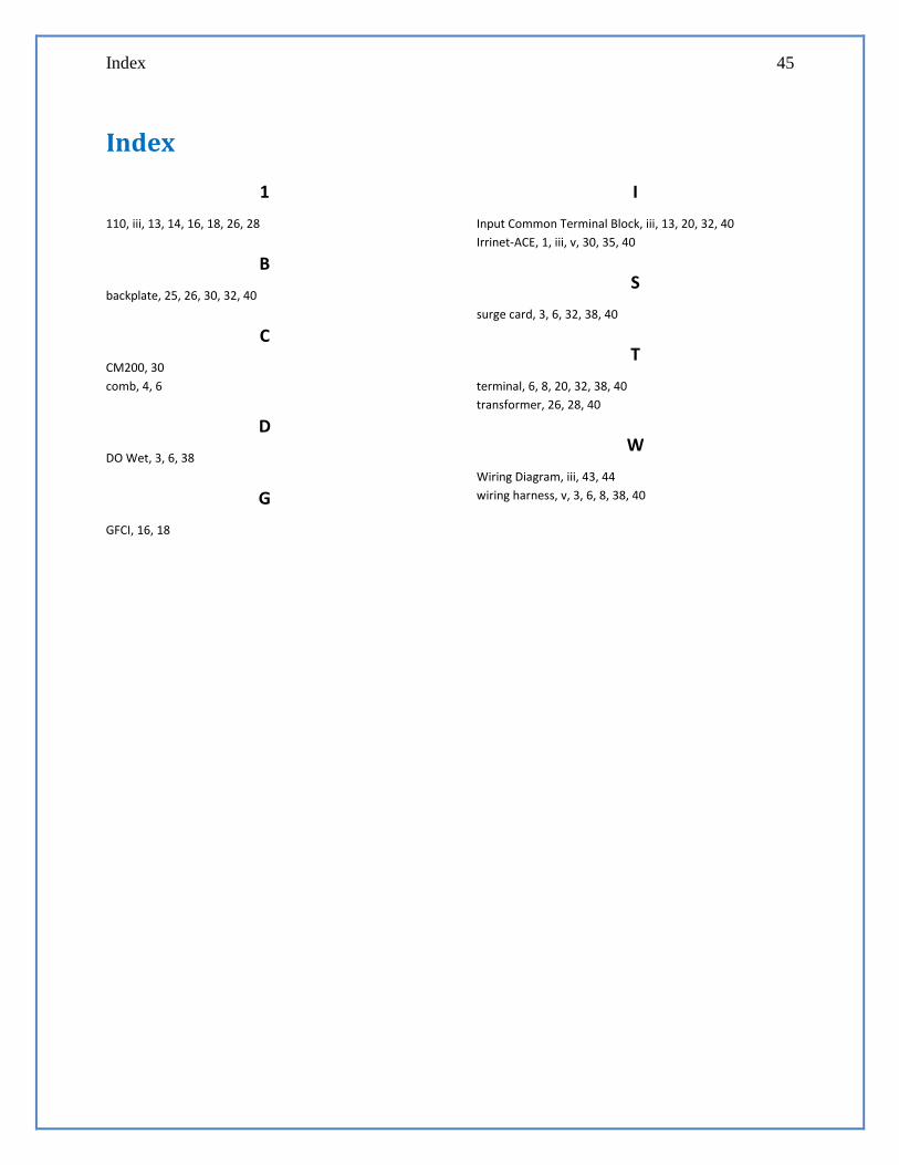
Index
1
110, iii, 13, 14, 16, 18, 26, 28
B
backplate, 25, 26, 30, 32, 40
C
CM200, 30
comb, 4, 6
D
DO Wet, 3, 6, 38
G
GFCI, 16, 18
I
Input Common Terminal Block, iii, 13, 20, 32, 40
Irrinet-ACE, 1, iii, v, 30, 35, 40
S
surge card, 3, 6, 32, 38, 40
T
terminal, 6, 8, 20, 32, 38, 40
transformer, 26, 28, 40
W
Wiring Diagram, iii, 43, 44
wiring harness, v, 3, 6, 8, 38, 40