iron removal plant in ferro-cement … · in ferro-cement. ferro-cement isathin walled type...
TRANSCRIPT

IRON REMOVAL PLANT
IN
FERRO-CEMENT CONSTRUCTIONAND MAINTENANCE
ui|-

CONTENTS
I. INTRODUCTION
II. TOOLS
. SPECIFICATION
IV. CONSTRUCTION
V. OPERATION
VI. MAINTENANCE
LIBRARY IRCSox 93190, 2509 AD THE HAGUE
Tel.: +31 70 30 689 80Fax: +31 70 35 899 64
\ R C O 0 E :

•Al SliMi
( I ) INTRODUCTION
The water quality problem as identified by NEERI team during 1986-87 in Phulbani
District is mainly of excess iron. It has been observed on-the-spot and further confirmed
by detailed instrumental analysis that most of the tubewell water contain high concen-
tration of iron. Maximum concentration which was observed in Phulbani District is 17.1
mg/L. The acceptable norm for iron content is 1 mg/L Interestingly, wherever alternate
source of water such as open well, nallah orchuas is available, the villageers preferthese
sources for water collection. Wherever iron content is high in tubewells, villagers do not
use this source for drinking purposes because of organoleptic considerations, but make
use of it for washing, bathing and other purposes. The general complaint made by
villagers is that of blackening of rice and tea while using the tubewell water which
contains high iron. Water kept overnight in vessels leave a brownish-black deposits on
the walls of the container. It was confirmed that villagers, particularly women folk, while
bathing complain of sticky hair when they use tubewell water. A typical phenomenon
observed among villagers of Phulbani district was blackening of teeth and nails wherever
they are using heavy iron contained tubewells.
Nearly 70 percent of rural drinking water needs in India is met from ground water
resources. Ground water in general do not need any special treatment, but in parts of
our state ground water contain excessive iron. Iron when present in water in concentra-
tion greater than 1 mg/L impacts a typical metallic taste. From aesthetic and economic
considerations excess iron (>1.0 mg/L) has to be removed from potable water.
Iron in ground water may be present in different forms and its removal can be
effected by simple methods such as aeration with or without sedimentation followed by
Alteration. An iron removal plant, attached to the hand pump, will remove most of the iron
from the water, thus making it acceptable for the village.
The iron removal plant in this unit, is based on DANIDA's design and is constructed

in Ferro-cement. Ferro-cement isathin walled type reinforced cementconcrete, in which
the mortar is reinforced with either a single or multiple layers of wire meshes welded with
small diameter steel wires.
There are two types of ferro cement. Iron removal plants now in operation in
Kandhmal district namely (1) Cylindrical type and (2) Rectangular type. Out of the two
the cylindrical type is easier for construction at much lower cost. But rectangular type
though requires better workmanship shows excellent results in reducing the iron content
to almost nil and also the maintenance is lesser as compared to cylindrical type.
In this type of rectangular ferrocement iron removal plant, iron is removed through
aeration and then sedimentation and finally filteration. Firstly this type of IRP has been
installed over the ground adjacent to tubewell and the water from the tubewell will be
entered into the aeration tank by lift and force method. But now the present design has
been made in which the total tank will be sunk 2'0" depth below the ground and the
tubewell will be raised 1'6" height by putting one 1'6" length 6" dia G.I. short piece and
finally the water from the tube well will go to the aeration chamber by gravity. This
prevents frequent leaking of gland in the water chamber. The step by step method of
construction of rectangular ferrocement IRP is given below.

"fljLI v,UJ.,,!.i , i,ijji.^*.^j||j^i,^"Wih«:^':.i*i(^i^.rt^™(;vi-vi+*<.P:'».-.t,.
;•:,... - • • • -
( H ) TOOLS
The following tools are required for construction of ferrocement structures,
(a) SKELETON MAKING / REINFORCEMENT WORK :
1. Measuring tape 1 No.
2. Chisel (25 mm width) small 1 No.
3. Hammer (2 kg) 1 No.
4. Bar bending key for 6 mm rod 1 No.
5. Bar bending slab (Flat slab with nails) 1 No.
6. Mesh cutter (16-18 gauge wire) 1 No.
7. Wire tying key 1 No.
(b) PLASTERING / MASON'S WORK :
1. Trowel (small size) 1 No.
2. Trowel (medium size) 1 No.
3. Long strip trowel 1 No.
4. Spirit ievel (15 cm) 1 No.
5. Plumbing bob 1 No.
6. Pan (Tasla) 1 No.
7. Tamping rod 1 No.
8. Wooden trowel 1 No.
9. Spade 1 No.
10. Sieve for size (0-2 mm) 1 No.
(c) MISCELLANEOUS ITEMS :
1. Chalk marker4 pieces
2. Lime Powder 1.5 kg
3. Thread (Jute Thread) 1 kg
4. Bucket and Mug 1 set
5. Old newspapers 4 kg
6. Bricks 100 Nos. 'jfeZ

( H I ) SPECIFICATIONS
Materials for construction of ferro-cement iron-removal plant:
1. Cement - Ordinary portland cement
2. Sand - Coarse medium sand of size 0-2 mm, free from silt, clay or organic
contamination.
3. Welded 18 gauge wire mesh of 13 mm size - Mild steel not galvanised (for tank
body)
4. Welded 18 gauge wire mesh of 20 mm size - mild steel (for porforated filter slab)
5. Tying wire - M.S. of 22 gauge
6. Mild steel rod - 6 mm diameter
7. PVC slotted pipe - PVC pipe slotted on half the side with 13 mm spacing and 3 mm
holes.
NOTE : 1. Use 1 kg of water proof compound per bag of cement.
I

BILL OF QUALITIES
(A) CYLINDRICAL IRON REMOVAL PLANT •
The following materials are required for Tank size of;Diametre ' •_ 1,20 M.HeightWall Thickness
1.05 M.35 mm
SI.No.
1
2
3
4
5
6
7
8
9
10
11
12
13
14
15
16
17
18
Materials
Cement
Medium coarse sand (0.2mm)
Steel rod (6mm dia M.S)
Welded wire mesh - 13mmWelded wire mesh - 20mm
Store chips
Bricks
Water-proof compound
Tying wire - 22 guage
Old Newspaper
Jute rope
15mm PVC pipe
Brick khoa
110mm PVC end cap
110mm PVC pipe
100mm dia 10" long G.I. short piece
100mm dia G.I. threaded flange
100mm dia M.S. blank flange
25mm G.I. socket
Quantity
6 bags
0.42 Cum
20 Kg
6.6 m2
1.5 m2
0.30 Cum
100 Nos.
6 Kg
1 Kg
3 Kg
1/2 Kg
9.0 M.
0.21 Cum
3 Nos.
3.0 M.
1 No.
1 No.
1 No.
2 Nos.
Approx. cost(Rs.)
780.00
150.00
320.00
1065.00194.00
170.00
100.00
126.00
30.00
30.00
20.00
60.00
30.00
180.00
600.00
100.00
142.00
228.00
40.00

BILL OF QUANTITIES
(B) RECTANGULAR TYPE :
The following materials are required and the approximate cost of each item is givenbelow.
SI.No.
1.
2.
3.
4.
5.
6.
7.
8.
9.
10.
11.
12.
13.
14.
15.
16.
17.
18.
19.
20.
21.
Materials
Cement
Medium coarse sand
Steel rod (6mm dia)
Welded wire mesh - 13mm size
Welded wire mesh - 20mm size
Stone chips (6mm size)
Water proof compound
Tying wire - 22 gauge
Old newspaper
Jute rope (Thread)
K.B. brick
Brick Khoa
110 mm PVC pipe
110 mm PVC end cap
100 mm G.I. short piece
100 mm G.I. threaded flange
100 mm M.S. blank flange
25 mm G.I. Bend for overflow
25 mm G.I. socket
PVC Tube (16 mm size)
25 mm dia short piece (0.40 m long)
Suitable pipe fitting for tap & elbows
Quantity
9 bags
1.00 cum
35 kg
13.14 sq.m
1.10 sq.m
0.40 cum
9 kg
11/2kg
4 kg
1 kg
100 Nos.
0.35 cum
3.0 m
3 Nos
2 Nos
2 Nos
2 Nos
1 No
2 Nos
15 mtrs
1 No
1 set
Approximate Costin Rupees
1125.00
220.00
565.00
1980.00
144.00
170.00
190.00
45.00
40.00
40.00
100.00
50.00
600.00
180.00
200.00
290.00
456.00
25.00
20.00
125.00
50.00
100.00
7

SI.No,
22.
23.
24.
25.
26.
27.
28.
29.
30.
31.
32.
33.
34.
Materials
15 mm PVC pipe for filter plate
1/2"x2" Img Nuts
1/2" bolts
Rubber insuration
32 mm G.I. pipe
32 mm G.I. elbow
12 mm B.S. connecting rod
150 mm G.I, pipe (short piece
fitted with hand pump)
Filter media
6 mm to 8 mm size gravel
10 mm to 12 mm size gravel
19 mm to 38 mm size gravel
Coarse sand as filter media
Labour for earthwork in excavation,
construction of tanK. aeration
chamber, filter plates, lid slabs.
construction of inspection chamber
and drain.
Labour for fitting, fixing and
washing of the filter media
Labour for making slotting of
PVC pipes
Construction of one no. soak pit
(1 m dia & 1 m depth)
Quantity
6.0 m
8 Nos
8 Nos
3 kg
2.0 mtr
2 Nos
1 No of 3.0 mL
0.45 m
0.17 cum
0.04 cum
0.04 cum
0.08 cum
Total
1 Mason +
2 Helpers
for 10 days
—
—
—
Approximate Costin Rupees
40.00
28.00
12.00
102.00
190.00
90.00
120.00
260.00
170.00
48.00
48.00
80.00
7903.00
1080.00
180.00
120.00
717.00
Grand Total 10000.00
(Rupees Ten Thousand only)

*•'*-- , . : , i\
( I V ) CONSTRUCTION
(A) CYLINDRICAL TYPE
Tank diameter : 1.2 m
Height : 1.05 mt
This covers the step-by-step procedure for construction of iron-removal plants over
a period of five days.
STEP I : SKELETON CAGE WITH MESH FRAMEWORK
- Steel rods to be cut and bent as per Sketch I and Sketch II
- Place rings at a spacing of 0.35 mt
- Tie the welded mesh and fold in the excess mesh at the base
Materials :
1. Steel bar 35 m
2. Tying wire - 1/2 kg cut into 15 cm strips
3. Mesh 18 gauge (13 mm) - 4'0" ht x 12'9" long = 4.75 sq.m
Labour Required :
Bar-bender/mason 1 for 1 day
Helper 2 for 1 day

(A) Base &Wall 2Nos. 3.28 each , 05 1.05
I
(B) Partly in base in wall 4 Nos. 1.40 each ~T1.05
1.18
T1.05
1.35
(c) Ring in wall 4 Nos. 3.87 each f \/TTT-i-nim r" '•Mm-J(3.77 + 0.10)
Ring in base 1 No. 1.98(1.88 + 0.10)
DETAILS OF STEEL BAR FOR BASE AND WALL(6 mm)
Fig. I
10
^

Steel bar 6mm in base & wall
(A) (B)
Square welded mesh
(C) Steei bar ring 6mm in wall.
Steel bar ring in base
0.35mmspacingbetween
rings
FIG. II
DETAILS OF STEEL REINFORCEMENT
11

STEP II : FOUNDATION AND 3ASE CASTING
1. Clean the site and level the surface
2. Draw a circle of radius 0.8 m with lime ~c
3. Dig 20 cm in the marked area
4. Cover with stone chips, add water ana ccmpact to a depth of 16cm.
5. Now mark a circle with radius 0.65 cm and place the bricks on the
outside of this circle.
6. Lay concrete mortar (1:2:4) inside rhe circular mark, to a thickness
of 4 cm. Place the skeletal cage on the first layer and place remaining mortar on the base
of skeleion, about 3 cm in thickness. Sprinkle with water and cover with wet gunny bags
or leaves. Allow to set for at least aight hours.
Materials :
1. Cement - 0.75 bags
2. Sand - 0.50 bag
3. Stone chips - 3 bags
Labour Required :
Mason 1 No. Two hours
Helper 2 No. Two hours'
12

STEPH
Filling excavated sitewith concrete
Placing the skeletalmesh in position

STEP 111 : FILTER PLATE FRAMEWORK AND PLASTERING
1. Straighten and cut the steei bars acccrcing to given aesign in
Figure-Ill.
2. First make the main ring; then tie all the rods with the edge of the
ring.
3. Cut the 20 mm wire mesh of dia 0.55 m
4. Place over rings and tie in a number of places (about 50)
5. Cut about 130 pieces of 6 cm pipe from dia 20 mm.
6. Embed pipe in the wire mesh.
7. Mix (1:3) and apply 5 cm thick layer on the entire ring. Avoid filling
tubes.
3. Fix two handles in the slab.
9. Allow to cure for seven days by sprinkling and covering with loaves
or wet gunny bags.
Material :
1.
2.
3.
4.
5.
3.
Steei bar 6 mm
Tying wire
Wire mesh
PVC tube 20 mm
dia 6 cm length
Sand
Cement
15m
200 gm
1.5 m2
8.5 m (130 pcs)
1 bag
1/3 bag
Labour Required :
Mason 1 No Remaining part of the day
Helper 2 No Remaining part of the day
14
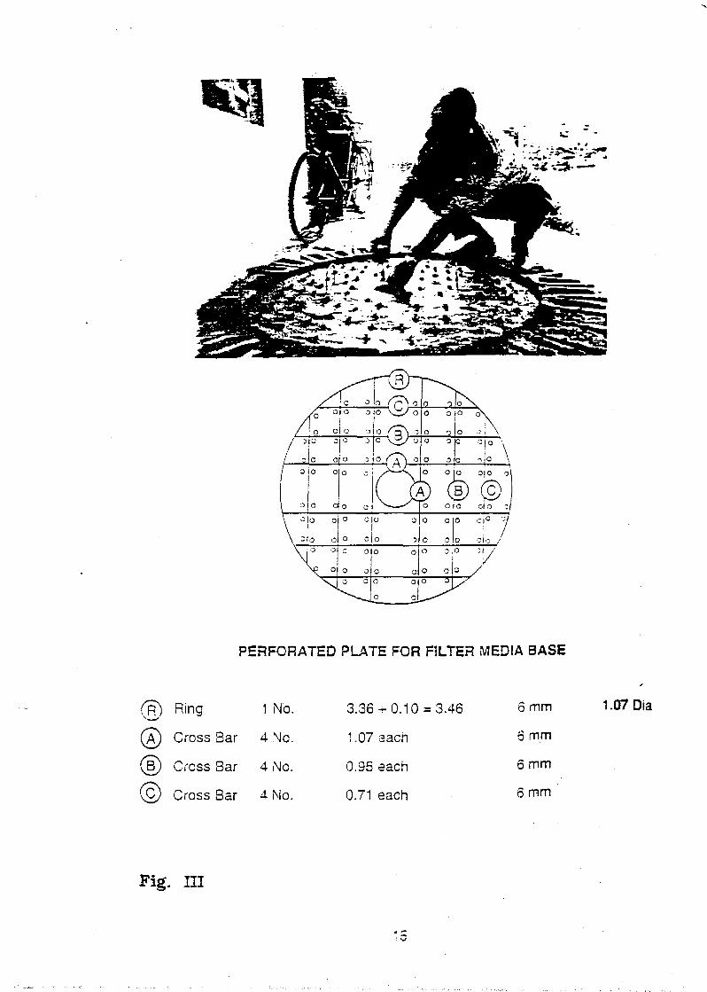
PERFORATED PLATE FOR FILTER MEDIA BASE
( R ) Ring 1 No.
Cross Bar 4 No.
Cross Bar 4 No.
,C) Cross Bar 4 No.
3.36^0.10 = 3.46
1.07 aach
0.95 each
0.71 each
6 mm
6 mm
6 mm
6 mm
1.07 Dia
Fig. HI

STEP !V PROJECTION FOR RESTING FILTHS PLATE
Make a mould by clacing vertically on the rsice of the skeleton cage.
leaving 5 cm between the cage and edge cf trick
Cut the mesh and place the drain pipe with oiar.K flange
Fill/pack the mortar (1:2:4) inside, between the crick mould and the
skeleton wall
After two hours, remove the bricks from the mould
Sprinkle with water and ailow to set overnignt
Material :
1. Cement - 1 bag
2. Sand - 2 bags
3. Stone chips - 4 bags
4. Drain-pipe with blank flange - 1 Nc.
Labour Required :
Mason - Approx. two hours
Helper - Two hours
Note : A newspaper sheet is held on the outside: while concrete is poured
into the gap.

STEP - IV
moid prepared by placingbricKs vertically inside theskeletal frame

,rt:u
STEP V AERATION CHANNEL :
Cut and bend the wire mesh into 0.4 m x 0.3 m x 0 4 m size
Place the cap of 100 mm dia pipe. Mark the size and cut a hole
bottom of the channel !j
Tie old newspapers around the framework • &
Pour 1:3 from the inside of the framework ?
Allow to set for two hours /
Cut and insert PVC pipes for marking holes j •.
Leave it for twentyfour hours ' ^
Next Day :
1. Remove newspapers without damaging the plaster on thf
2. Plaster the outside wall with extra care. Total thickness
chamber is about 20 to 25 mm. Leave for at least eight
3. Pull out the PVC pipes. |
4. Allow to cure for seven days by sprinkling with water and
wet jute bags or even leaves.
in the
lift-
Material :
1. Wire mesh
2. Cement
3. Sand
4. PVC TUBE 8 MM dia •
Labour Required :
Mason - 2 days
Helper - 2 days
1.4 sq mtrs
1/2 Bag
2 Bags
15 mts
18

'Ateided
0.4°
AERET10N CHANNEL OR CHAMBER
19

STEP VI PLASTERING OF THE TANK WALL .
Cut the wire mesh and place vent pipe and cutlet pipe at desires .'ccaticn
Tie old newspapers around the skeleton cage, /vith a string
Pack piaster (1:3) from the inside of the cage about 20 cm thick
Allow tc set for twentyfour hours
Next Day :
Remove newspapers, without disturbing the piaster on the inner wall
Plaster outside wail
Total thickness of tank wall 30 to 35 mm. Leave overnight for setting
Cure forten days by filling the tank with water ana covering with jute bags
or ieaves
Material :
1. Cement
2. Sand
3. Pipe for outlet
4. Pipe for vent
2 3ags
5 Bags
1 No.
1 No.
Note :
i) Vent pipe to be piacad approximately 5 cm from the top edg«.
ii) The outlet pipe to be placed, leaving 0.10 cm from top edge of tank.
Elbow bends and top to be provided such that 50 cm dear space is
available between bucket and tap.
Labour Required :
Mason
Helper
1 for 2 days
1 for 2 days
-::'B^:rs^• ! I I ' II ' 111 ' I
TT

STEP VII CASTING THE LIDS :
The lid is cast in three parts - two semi-circular section for the tank andone rectangular section for the aeration chamber
Provide reinforcement, as per design
Plaster with mortar (1:3:6) thickness of plaster 20 mm
Make a hole of the required size for inlet of pipe in the second lid
Allow to cure for seven days by sprinkling water and covering with jute
bags or leaves
Material :
1. Steei bar - 6 mm - 22 m
2. Cement - 0.5 bag
3. Sand - 2.0 bag
4. Stone chips - 3.0 bag
Labour Required :
Mason - 1 day
Helper - 1 day
STEP VIII CONSTRUCTION OF PILLAR AND WASH OUT CHAMBER
Brick Pillar Size 0.25 x 0.25 x 0.40 mt in cement mortar (1:4) and
plastered in cm. (1:3)
Wash out chamber below ground level size 0.75 x 0.60 x 0.60 with brick
masonry in cm. (1:4) and plastered in cm. (1:4)
Material :
1. Cement - 1 bag
2. Sand - 3.50 bags
3. Brick - 100 Nos.
Labour Required :
Mason - 1 No. 1 day
Helper - 1 No. 1 day
21

k ,11
DETAILS OF STEEL BAR FOR LID
STEP -
LID No. 1 LID No. 1
AB
LID No. 2
3 Nos. 1.18 m each9 Nos. 0.33 m each
LID No. 2
LID1
A 2 Nos. 1.17 eachB 2 Nos. 1.02 eachC 2 Nos. 0.73 . eachD 2 Nos. 1.55 eachA1 2 Nos. 0.44 eachB1 4 Nos. 0.40 eachC1 4 Nos. 0.32 each
22

Reinforcement for Semi Circular Cove'ti
Cover Lid of aeration chamDer with hole for delivery 3ioefrom n2nc cumn

Plant Assembly
Assemble the plant by the following steps :
1. Lower the perforated slab into the tank till it rests on the projectedsurface.
2. Now place :10 cm thick layer of boulder 10 nun - 12 nun size20 cm thick layer of gravel - 6 nun - 8 mm size10 cm of coarse sand > 3 mm
3. Place aeration chamber over the tank
24

4. Fix the down takePVC pipe to thebase of aeration
tank
5. Place a row of pebbleson the chamber andthen fix the PVC pipe
such that the slottedsection is on thelower end.
6. Cover with lids

3) RFfTTANGULAR TYPE
Tank size : Length -1.705 m (outside)
Width - 0.995 m (outside)
Height -1.05 m
Rectangular 1RP consists of two tanks
(i) Settling tank of size 0.925 m x 0.675 m x 1.05 m
(ii) Filter tank of size 0.925 m x 0.925 m x 1.05 m
The construction of rectangular ferrocement iron removal plant requires 10 days. The
step by step construction procedure is given below :
Step-I: SKELETON CAGE WITH MESH FRAMEWORK
6mm steel rods to be cut and bent as per sketch I and sketch II.
Place rings at a spacing of 0.26m.
Tie the welded mesh and fold in the excess mesh at the base.
Materials :1. Steel bar (6mm dia M.S.
2. Tying wire
3. Welding mesh 18 gauge
(i) Side wall & inside wall
(ii) Bottom slab
(iii) Overflow chamber
Labour required :
Bar-bender/mason - 1
Helper - 2
rod) --
(13mm)
I
-
No. for 1
Nos for 1
66
1
7.
2.
0.
10.
dayday
.0 m
.Okg
.46 sq.m.
00 sq.m.
72 sq.m.
18 sq.m.
Step-II : FOUNDATION AND BASE CASTING
1. Clean the site and level the surface.
2. Mark the site with lime powder of size 2.30 m length x 1.80 m width.
3. Dig the rectangular area as marked upto a depth of 0.75 m.
4. The brick khaoas will be laid including watering & well rammed for a size of
1.905m x 1.195m x 0.16 m depth.
5. Now the bricks will be placed as shuttering of 1:2:4 concrete with cement,
sand & stone chips of size 1.905 m x 1.195 m.
6. The concrete of 1:2:4 with 6mm size stone chips will be laid up to a thickness
25

of 4cm with bottom size of 1.905m x 1.195m. Then the skeleton cage will be
placed over the first layer and the remaining concrete (1:2:4) will be placed
on the base of skeleton, about 3cm in thickness for bottom size of 1.805 m
x 1.095 m. Then the 2nd day work will be over and the concrete is allowed to
set for at least eight hours.
[Materials :
1. Cement -
2. Sand
3. Stone chips -
1 bag (50 kg)
0.07 cum
0.14 cum
[Labours Required :
Mason
Helper
1 No for 1 day
2 Nos. for 1 day
i
Step-Ill : PROJECTION FOR RESTING FILTER PLATEMake a mould with bricks by placing vertically on the inside of the skeleton
cage, leaving 8cm between the cage and edge of brick upto a height of 25cm.
Cut the mesh and place the drain pipe with blankflange both the filtertank and
setting tank.
Fill the concrete (1:2:4) inside, between the brick mould and the skeleton wall.
After two hours, the bricks will be removed.
Cut the wire mesh and place the vent pipe and outlet pipe at desired location.
Tie old newspaper around the skeleton cage with jute rope.
Pack the paster (1:3) from the inside of the cage of filter chamber only.
Allow to set for one night.
Materials :
1. Cement
2. Sand3. 1" Scocket for outlet
4. 1" Socket for vent
5. Stone chips
Labour Required:
Mason - 1 No. for 1
Helper - 2 Nos for 1
-
-
--
-
day
day
1
0.1
1
0.
bag (50 kg)
10 cum
No.No.
16 cum
27

Step-IV : INSIDE PLASTERING OF THE TANK WALL
Pack the plaster (1:3) from the inside of the settling tank.
Remove the brick shuttering of the projection for filter plate.
Plastering and punning of filter tank inside.
Materials :
1. Cement
2. Sand
Labour Required :
Mason
Helper
1 bag (50 kg)
0.10 cum
1 No. for 1 day
2 Nos for 1 day
Step-V : FINISHING OF SETTLING TANK INSIDE AND OUTSIDE
PLASTERING OF TANK WALL
Plastering and punning of inside of settling tank.
Remove the old newspaper from the tank wall.
Pastering of outside short wall of filter tank.
Materials :
1. Cement
2. Sand
3/4 bag (37.5 kg)
0.08 cum
Labour Required :
Mason - 1 No. for 1 day
Helper - 2 Nos for 1 day
Step-VI . : PLASTERING OFREMAINING PORTION OR OUTSIDETANK WALL
Plastering with cement mortar (1:3) of the two long walls and one short wall.
Materials :
1. Cement
2. Sand
Labour Required :
1. Mason
2. Helper
1.25 bags (62.5 kg)
0.15 cum
1 No. for 1 day
2 Nos for 1 day
28

Step-VH : CONSTRUCTION OF BRICK PILLAR FOR OUTLET PIPEAN WASHOUT CHAMBER
Construction of brick pillar of size 0.25 m x 0.25 m x 0.45 m height including
plastering.
Construction of brick masonary wash out chamber of size 0.75 m x 0.60 m x
0.60 m height including plastering. This includes the following items.
(a) Earthwork excavation
(b) laying of bricks inside the earthwork.
(c) casting of 1:2:4 concrete
(d) brick work and plastering
Materials :1. Cement
2. Sand
3. Brick
1 bag (50 kg)
0.15 cum
100 Nos
Labour Required :
1. Mason
2. Helper
1 No. for 1 day
2 Nos for 1 day
Step-VIII : INSIDE PLASTERING OF AERATION CHANNEL ROD BENDING& BINDING OF LIDS AND FILTER PLATE
Cut and bend the wire mesh into 0.40m x 0.30m x 0.40 m
Cut one 6mm dia rod of length 3.94 m around the top of the wire mesh of size
1.67m x 0.30m.
Place the 110mm PVC pipe. Mark the size and cut a hole in the bottom of the
channel.
Tie the old newspapers around the framework.
Pack the plaster with cement mortar (1:3) from inside of the framework.
Allow to set for two hours.
Cut and insert PVC pipes for making holes on both sides of the aeration tank.
Leave it for one night.
During the two hours idle period, the rods for lids is to be cut and tied with
binding wire. (As per the Fig. 4)
Cut the 6mm M.S. rods for perforated plate for filter media with required
dimension (As per Fig. 3) and tie them with binding wire.

Materials:
1. Wire mesh2. Cement
3. Sand
4. PVC tube of 8mm dia -
5. 6mm dia M.S. rods
Labour Required :
Mason - 1 No. for 1day
Helper - 2 Nos for 1 day
2.36 sq.m
0.50 bags (25 kg)
0.08 cum
15 mtrs
44.0 m
Step-IX : OUTSIDE PLASTERING OF AERATION CHAMBER ANDPREFABRICATE OF OVERFLOW CHAMBER
Remove the old newspapers without damaging the plaster on the inside wall.
Plaster the outside wall with extra care. Total thickness of the aeration
chamber is about 20 to 25 mm. Leave for at least eight hours.
Pull out the PVC pipes from the side of aeration tank.'
Allow to cure for seven days by sprinkling with water and covering with wet jute
bags.Cut the wire mesh for overflow chamber in 'L' shaped with dimensions 0.25m
x 0.25m x 0.90m height.Pack the plasterwith cement mortar (1:3) on one side of the overflow chamber
and leave it for one night.
Materials :
1. Cement - 1 bag (50 kg)
2. Sand - 0.10 cum
3. Wire mesh for overflow chamber - 0.60 sq.m
Labour Required1. Mason
2. Helper
1 No. for 1 day
2 Nos for 1 day
Step-X
UDS
CASTING OF LIDS AND PERFORATED PLATE FOR RESTING
FILTER MEDIA AND FINISHING OF OVERFLOW CHAMBER
The lid is cast in two parts
One rectangular of size -1.705 m x 0.36 m for aeration chamber
Another also rectangular of size -1,705m x 0.635m for the coverage of
tank.
30

Place reinforcement.
Cast in cement concrete (1:2:4) with 6mm stone chips. Total thickness after
plastering will be 50 mm.
Allow to cure for 7 days by sprinkling water and covering with jute bags.
[PERFORATED PLATE :
Place the reinforcement.
Cut the wire mesh (20mm size) of size 0.82m x 0.82m.
Place the wire mesh over the framework of reinforcement.
Cut about 120 pieces of 50mm length of pipe of dia 15 mm.
Embed pipe in the wire mesh.
Mix 1:3 cement mortar and apply 50 mm thick layer on the entire ring. Avoid
filling of the tube.
Fix two handle in the slab.
Allow to cure for 7 days by sprinkling and covering with wet gunny bags.
OVERFLOW CHAMBER :
Finishing the overflow chamber in cement mortar (1:3) including punning.
Materials :
1. Wire mesh
2. PVC tube
3. Cement
4. Sand
5. 6mm stone chips -
Labour Required :
Mason
Helper
0.81 sq.m.
6.0 m
1.5 bags (75 kg)
0.17 cum
0.10 cum
1 No. for 1 day
2 Nos for 1 day
' • : ' ' / " :

FIG. l(a)
SKELETON CAGE WITH REINFORCEMENT DETAILS
334.f
334• 334
334
iT334
1
334 334 i 334.
Base & wall 2 No 3.77 m each
T1.05
(B) Base & wall 6 No 3.06 m eachT.05
41.05
0.96
(6) Base
Ring in wall
2 No 1.67 m each ^— 1 67 ^
—>l 0.15
8 No 2.78 m each
1.67 >l
Partition wall vertical Rod - 4 No 1.35 m each
0.96
t1.05
K—0.30—»
L Partition wall Horizontal Rod - 4 No 1.11 m each T0.08
L0.95
32

262 mm
CROSS SECTION OF SKELETON CAGE
FIG. l(b)
T
262 mm1.05 m
262 mm
0.96 m 0.71 m
262 mm •Partition Wall Rod
1.67 m

-o-1.40 mtfl
AERATION CHANNEL OR CHAMBER
-o-o-o-o-o-o--o-
-o-o—o-15mm O Hole
40 mm 4> Hole
0.30 m
1.67 mt-
34

PERFORATED PLATE FOR FILTER MEDIA BASE
FIG. 3
o oo oo o
oo
oo
ooo
1°D
CO
"O
o oo oo o
o oo oo o
o oo oo o
o^ oe—(A)
o oo o
(Jo o
o To ooo o
oo o
ooo
ooo
ooo
oo
oo
ooO O
o oo oo o
o oo oo o
o oO O i
o oo o
t-136 mm-)
o oo o
o o<M36 mm-4o
o |o- 136 S _
o o<-136 mm-o
o o<-136 mm-)o! O
o o<-i36 mmo o
o O TO o O i O O O
ooo
ooo
oo
oo
°oo So
CO
o TO
ooo
ooo
ooo
ooo
ooo
ooo
ooo
ooo
oo
oo
Jooo <so
CO
O TO
ooo
ooo
ooo
ooo
o'oo
onO !
6 mm Rod 7 No 0.82 mt each
j3) 6 mm Rod 7 No 0.82 mt each

LID FOR TANK
1.67 mt.
FIG. 4
d
.-G.15*
ii
1
! ! ! ! ! ;
! i i ! >• i
1]
11
0.62 mt.
0.25
1.67 mt.
j
>
! i
0.34 mt.
OVER FLOW CHAMBER

( V ) OPERATION
p h e operation of the iron-removal plant is based on the following principles :
trickling aeration
pre-setting
sedimentation
up-flow filter
fWater from the handpump is fed directly to the PVC aeration pipe by force lift
jement. This is achieved by modifying the water tank and providing gland packing
}' rings. Aeration is achieved by passage of water through the slots of the aeration
id then over a bed of pebbles in the aeration tray. Passage of water through slots
ses the surface area of the water accelerating the rate of oxygen absorption,
luent passage of water over a bed of pebbles in the aeration tray acts like trickling
I aeration.
The aerated water moves to the bottom of the pre-setting chamber through a PVC
i. Here the oxidation reaction 'is completed and the oxidised particles settle under
scent condition. The settled water passes through a bed of gravel and coarse sand
i upward direction. The ferric particles either settle at the base of the tank or will get
ipped in the filter media.
Clear water after filtration is collected over the media and is made available to the
iumer, through an outlet.
37

( V I ) MAINTENANCE
To ensure that the iron-removal plant works effectively, periodic back-washing
>uld be required. Even though the iron level at the outlet of the filter remains within the
|acceptable limit of 1 mg/l the general filter condition and head are considered for fixing
i two month interval for backwash.
During the back washing of the settling tank, the aeration chamber is cleaned by
removing the lid and pebbles, washing the pebbles and replacing them in the chamber.
The back-washing of the main unit is done by closing the clear water outlet and pumping
I water into the plant, till it starts to over-flow from the vent. Open the flange on the drain-
pipe and the head of a column of 400mm of water over the filter bed and the diameter
of the back-wash outlet creates a high back-wash rate for cleaning the trapped iron-
oxides from the media and scouring the settled matters from the settling basin. This
process is done 2/3 times, consecutively. The filter media can be taken out, cleaned and
replaced. This operation may be required once in two years or so. Other than back-
washing, the plant Has virtually no maintenance need. The labour component for back-
washing is 3/4 hours every two months.
Community participation is the key factor for the success of I.R.P. implementation
programme. Social mobilization should be the primary and integral partof this programme.
The handpumps to which the IRP's WQUjc^^teched, should have a community
based maintenance system and there need£|obej|clear prior understanding that the
same beneficiaries would be responsible f o ^ ^ ^ ^ i t e n a n c e of the IRP, with guidance
from experts, as and when necessary.

AElWION CHAMBER
O O Q O O O O O O O O
a 5 o o — o o o o
o o O . O O O ' O Q Q O G Q
PV C PIPE
-thickness'
t f r
FUter media slab
tCleaning pipe
:2 3 Ce»nen-t Concrete 5 cm th.
DETAILS AND SECTION PLAN OF FERKDCEMENT TANK
iw-39

(n
r