iris power pdtracii · 1% development of iris power partial discharge monitoring the development of...
TRANSCRIPT
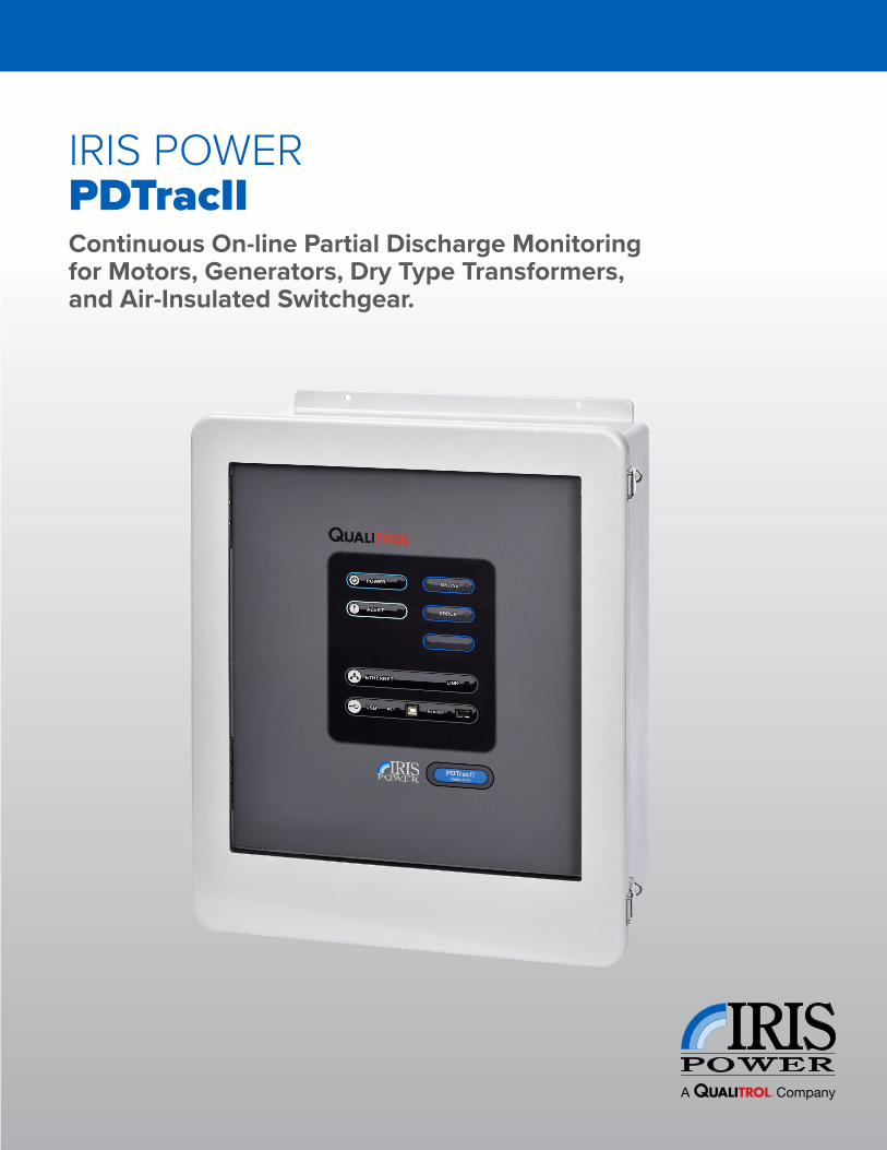
IRIS POWER PDTracIIContinuous On-line Partial Discharge Monitoring for Motors, Generators, Dry Type Transformers, and Air-Insulated Switchgear.
Partial Discharge Is A Leading Symptom Of Failures On Stator Windings and SwitchgearInsulation problems are one of the principal causes of forced outages for generators, motors, switchgear and dry type transformers which result in considerable damage and lost revenues. Periodic online monitoring of partial discharge provides a cost effective and proven technique to minimize the risk of unexpected failures.
Partial Discharge monitoring has become an important tool for condition based maintenance by identifying risks of failure caused by abrasion of insulation, loose stator windings, thermal degradation of insulation and manufacturing defects.
Iris Power online partial discharge monitoring instruments have accurately identified problems on many hundreds of generators and motors with hundreds of case studies and dozens of published papers by Iris Power customers that confirm Iris Power partial discharge monitoring instruments can help:
• Prioritize assets needing immediate maintenance
• Identify and repair damage at an earlier stage
• Avoid in-service failures
• Reduce outage frequency when machine conditions present low risk of failures.
• Obtain information regarding the type and location of maintenance required prior to outages
• Reduce overall cost of maintenance
Global Acceptance Of Online Partial Discharge MonitoringPartial discharges in degrading high voltage stator windings give rise to small current pulses that travel through the stator winding. The magnitude and number of these pulses depend on the degree of insulation deterioration. As the magnitude and number of partial discharge current pulses increase, the amount of electrical insulation deterioration is also increasing.
Partial Discharge monitoring has won worldwide acceptance across utilities, major industrial companies and manufacturers. Iris Power has provided products for partial discharge monitoring on over 16,000 assets globally in addition to partial discharge monitoring being recommended in industry standards such as IEEE Standard 1434-2014, IEC TS 60034-27-2:2012 and IEC 62478-2016.
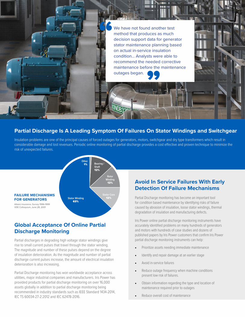
FAILURE MECHANISMS FOR GENERATORSAllianz insurance, Survey 1996-1999VDE Colloquium, June 28, 2001
We have not found another test method that produces as much decision support data for generator stator maintenance planning based on actual in-service insulation condition... Analysts were able to recommend the needed corrective maintenance before the maintenance outages began.
Avoid In Service Failures With Early Detection Of Failure Mechanisms
Bearing / Shaft12%
RotorWinding12%
Stator Core12%Stator Winding
63%
Other 1%

Development Of Iris Power Partial Discharge MonitoringThe development of Iris Power partial discharge testing instruments in 1990’s was funded by the North American utility industry (CEA and EPRI) to provide machine owners a method of detecting stator winding insulation problems and obtaining adequate data to make maintenance decisions independent of equipment manufacturers.
The PDTracII was designed specifically for monitoring partial discharges under normal electrical, mechanical and thermal machine operating stresses. There are now over 65,000 Iris Power partial discharge Epoxy Mica Capacitive Sensors installed across thousands of motors, generators, dry type transformers and metal glad switchgear globally that are monitored by Iris Power portable and continuous instruments.
Data Collection MethodThe online partial discharge tests are run continuously in a simple, safe and non-destructive manner based on sound principles that are recommended by manufacturers and industry standards such as IEEE Std. 1434-2014 and IEC60034-27-2: 2012.
The PDTracII automatically runs measurements in a sequence across all enabled inputs and sensitivity ranges which takes approximately 20 minutes before repeating the sequence.
Measurement results provided by the Iris Power PDTracII instrument include:
• Alerts indicating high partial discharge measurements
• Phase resolved “3D” data plots presenting raw data
• Summary “2D” data plots of analyzed Qm results
• Operating condition data
Termination Box
Computer Installed with PDTracPro & PDView
Iris Power PDTracII
Epoxy Mica Capacitors (80pF)Epoxy Mica Capacitors Installed In Motor Termination Enclosure
Sensor Installation and ConfigurationIris Power Epoxy Mica Capacitors (EMCs) are 80 pF capacitors that are used to attenuate low frequency from the generator since impedance is inversely proportional to frequency. The 60 Hz or 50 Hz power frequency is filtered with 100’s MΩ impedance while the high frequency partial discharge pulses up to 250 MHz easily pass through the EMC with only 10’s Ω impedance. This allows the PDTracII to monitor small partial discharge pulses of over 2 mV on machines rated over 3.3 kV.
Iris Power typically installs two 80pF epoxy mica capacitive couplers per phase on generators. Noise pulses originating outside the machine arrive at the sensor closer to the system first. Pulses originating in the machine winding arrive at the sensor nearest the machine first. This allows Iris Power instruments to automatically distinguish between noise and winding partial discharge.
Motors, small generators and transformers connected with over 30 m of cable between the machine and the switchgear can leverage just one epoxy mica capacitive sensor per phase and a PDTracII to automatically analyze the pulse shapes to separate distorted pulses originating from the system and other disturbances from machine partial discharges.
Epoxy Mica Capacitive Sensor

Data Analysis and Information OutputIris Power is foremost focused on providing a clear, reliable and repeatable result that allows the user to understand the true condition of the motor or generator and to make educated decisions for operations and maintenance. The PDTracII instrument has been designed to autonomously collect partial discharge data on a continuous basis and output the relevant information needed to provide a decisive means of:
› Identifying Partial Discharge Severity
› Identifying Probable Causes of Deterioration
› Comparing Relative Health Across EquipmentPeak Partial Discharge MagnitudePeak pulse magnitude (Qm) values are automatically evaluated by the PDTracII instrument and output to help understand the relative health of each asset. The Qm value is defined in IEEE 1434 and IEC 60032-27-2 to allow several means of comparison including the following:
Trending of Qm to show any major change in the rate of deterioration of the stator winding insulation.
Comparison of generator condition against similar machines using the freely available Iris Partial Discharge Severity Tables which are composed of over 550,000 test results collected across most makes and sizes of machines.
Machine Partial DischargeElectrical disturbances including partial discharges in the busbar or transformer as well as sparking of overhead cranes or on-site welding can create pulses similar to partial discharges. It is important to be able to understand the difference between power system disturbances and machine partial discharges to avoid false positive indications, to prevent unnecessary shut-downs and to avoid in-service failures.
The Iris Power PDTracII is designed specifically for equipment with at least 30 m of power cable between the machine and the switchgear. If this is not the case, Iris Power recommends the use of two epoxy mica capacitors per phase and the use of the GuardII monitor or a portable TGA-B instument to ensure machine partial discharges are viewed and analyzed separately from system disturbances.
Separation of System Noise Iris Power provides a solution that separates electrical noise similar to partial discharge and other disturbances in the power system from the asset partial discharges.
In cases where there is 30 m or more of power cable to the generator, high frequency system noises that resemble machine partial discharges are attenuated by the power cable.
The remaining low frequency disturbances from the power system are are eliminated using the Iris Power 80 pF capacitive sensors. The sensors attenuate all low frequency electrical noises below 40MHz leaving only the machine partial discharges to be analyzed. Pulse shape is then automatically analyzed to ensure only machine partial discharges are presented in the data output. Low frequency solutions like those using 1000 pF couplers do not block these frequency ranges.
Peak Partial Discharge Magnitude (Qm) Trend Graph Showing Increas-ing Rate of Partial Discharge Severity
Phase Resolved Partial Discharge Plot showing pulse magnitude (mV) and frequency (pulses per second) by phase angle in the machine
High frequency partial discharges above 40 MHz are automatically separated from low frequency noise by the PDTracII
0102030405060
0 5 10 15 20 25 30 35 40 45 50 55 60 65 70 75 80 85 90 95 100
Low Frequency Noise Blocked by 80pF Sensor
High Frequency Partial Discharges Measured by PDTracII
40 MHz
Pulse Frequency

Partial Discharge Pulse Measurement
Frequency Bandwidth 0.1 MHz - 350 MHz
Phase Windows 24 phase windows per cycle
Pulse Amplitude Range 2 mV - 34,000 mV10 Sensitivity Range Settings
Data Acquisition Time 5 s per magnitude window
Resolution 6 ns for EMCs
Ambient Sensors Ambient Temperature SensorAmbient Humidity Sensor
Recommended Sensors80 pF EMC (6.9 kV - 35 kV) 3 Sensor Inputs, IEC 60034-27-2 and IEEE 1434 Compliant
Synchronization Frequency 20 Hz to 120 Hz
Operating Conditions
Operating Temperature 0 oC to 55 oC ( 32 oF to 131 oF )
Relative Humidity Up to 95% non-condensing
Size 559 mm x 451 mm x 229 mm 22” x 17.75” x 9”
Data Download and Networking
Networking Capability Modbus over Ethernet (TCP/IP)
Manual Data Download USB Memory Stick
Software
PDTracPro and PDView Included
PDView Advanced Edition Optional
Options
Controlling Computer Details Available On Request
Remote Outputs 6 Analog Remote Outputs: 2 Outputs Proportional to the level of PD activity (+Qm and –Qm) per phase.
Remote Inputs 8 Remote Analog Inputs:Recording and Trending of equipment temperature,Voltage, Current, or Power.
Options For Hazardous Locations
Stainless Steel IP66 Enclosure with Available Certifications:
ATEX / IECex II 3G Ex nA nC IIC T4 Gc in compliance withEN 60079-0:2012/A11:2013 EN 60079-15:2010IEC 60079-0:2011 Ed. 6IEC 60079-15:2011 Ed. 4
C-US Class I, Division 2, Groups A, B, C, D T4 Ex nA nC IIC T4 Gc Class I, Zone 2, AEx nA nC IIC T4 Gc based onCAN/CSA C22.2 No. 61010-1-12 CSA Std. C22.2 No. 213-16 CAN/CSA-C22.2 No. 60079-0:15 CAN/CSA-C22.2 No. 60079-15:16 ANSI/UL 61010-1, 3rd Ed ANSI/ISA-12.12.01-2015 ANSI/UL 60079-0:13 ANSI/UL 60079-15:13
INMETRO Ex nA nC IIC T4 GcIn compliance withABNT NBR ISO IEC 60079-0:2013ABNT NBR ISO IEC 60079-15:2012
Product OverviewThe Iris Power PDTracII system provides automated, continuous partial discharge (PD) monitoring with configurable alarms that initiate on high partial discharge levels.
• PDTracII works with permanently installed epoxy mica capacitive sensors on motors, generators, dry type transformers and switchgear over 3.3 kV
• The PDTracII continuously collects partial discharge data to produce phase resolved plots and summary numbers (Qm and NQN) for trending and comparison.
• The PDTracII uses pulse shape analysis to reliably distinguish partial discharges from electrical interference (noise) in order to prevent false alarms when the monitored equipment is connected to the power system by >30 m of power cable.
• The test frequency range is from 40 MHz to 350MHz while working with 80 pF Epoxy Mica Capacitors (EMCs) and 2 MHz to 350 MHz with 1 - 2 nF capacitive couplers.
Dimensions
PDTracII Standard410mm W x 421mm H x 257mm D15” W x 16.5” H x 10.14” D
PDTracII Hazardous Location
550mm W x 740 mm H x 10mm D 21.5 “ W x 29.13” H x 10.29” D
The PDTracII is a Trademark of Iris Power LP - a Qualitrol Company
QUALITROL COMPANY LLC 1385 Fairport Road Fairport, NY, USA 14450 www.qualitrolcorp.com
VER 9 - 5 / 18
IR IS POWER LP3110 American DriveMississauga, ON, Canada, L4V 1T2 Phone: +1.905.677.4824Toll Free: +1.888.873.4747 [email protected]