iris-beginner tutorial - aavso.org · iris-beginner tutorial ... shot noise, are !) on recent...
TRANSCRIPT
IRIS-Beginner Tutorial
This tutorial provides a step-by-step procedure for processing digital images obtained in raw format to yield instrumental magnitudes which are used in the next step in our tutorial: processing the data using Excel. This process assumes that, in addition to a series of sequential star field images, dark frames, flat frames have been taken. This tutorial also assumes that you have already copied the images from your camera to some directory on your computer (this greatly speeds up processing).
IRIS is a powerful image processing utility with a command-line editor and a graphical interface (GUI). We attempt to highlight both methods below.
In this tutorial you will
1. Initialize IRIS2. Check raw images3. Load and convert images4. Perform Bias and Dark subtraction then Flat division5. Align and stack images6. Select the green channel of the images stack file7. Perform Aperture photometry.8. Option: Analyze each image instead stacking them
After these steps, the instrumental magnitudes are entered into a spreadsheet which will yield calibrated magnitudes which can then be submitted to AAVSO.
The spreadsheet performs both:
- the color correction to transform the green DSLR response to the Johnson's V standard
- the compensation of the differential atmospheric extinction between the stars of the image
This tutorial was written by GMara, bikeman, and Roger Pieri with editorial changes by bkloppenborg and screenshots by bikeman.
Note1, Version: We recommend using the latest version of IRIS (5.59 as of the time this document was reviewed: Aug-2011) because it implements several new features that make it easier to work with raw images.
Note2, Elapsed Time: When processing a series of images, IRIS will pause for some time to read, transform, calculate and save the images. The time needed for image registration could be long: several 10 seconds to minutes per image depending the image size and the computer. Only the final result of these calculations will be displayed as the current image or values in Output Box depending the operation.
Note3, Linux: For Linux users: This tutorial was tested under Ubuntu 10.04 using Wine 1.3.26 with IRIS 5.59. The only thing that does not work is the drag-and-drop of images files from Windows Explorer. You have to use the CONVERTRAW command in order to load a series of raw images files.
Note4, Need for Dark: Differential dark currents that generate a Fixed Pattern Noise (FPN) are depending of the technology level of the sensors, they are not determined by the physics fundamentals (but Random Noises: read noise, shot noise, are !) On recent sensors, like DSLR CMOS 14 bits, the dark noise is negligible in exposures shorter than 30 seconds. In that case the dark process would not apply but IRIS doesn't provide such option. One solution is to use "dummy" images (to see 4.1.2) for both bias and dark (a simple constant equal to the system offset of the Analog to Digital Converter (ADC) of the camera for the bias and "zero" for the dark)
Note5: IRIS Commands and GUIIRIS has been developed by Christian Buil during many years, at the beginning it was mostly a command-line type of software, a kind of toolbox. Along years many tools have been added as new commands and some connected to a GUI but not all. Existing commands/tools are apparently never modified but new ones are just added. That means older applications are not impacted by new versions: when something doesn't work this is normally not a version issue.
IRIS is down-loadable at: IRIS exe The definition of the newest commands is there. Various applications examples are at end of the page.
The definition of the commands up to V5.58 can be find (8/2011) at: IRIS Commands
As tools are not all available through the GUI (Graphical User Interface) we will have to use both ways: the old command-line prompt and the GUI.
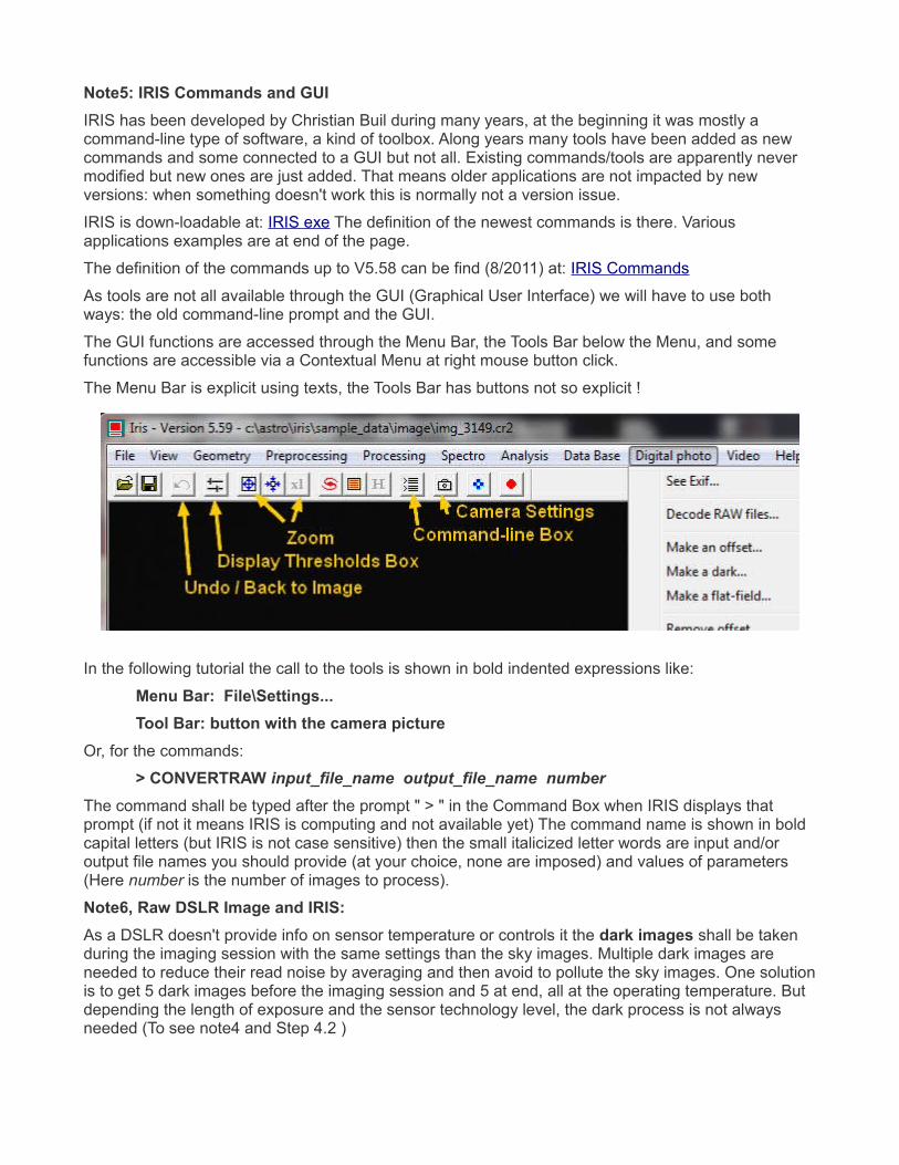
The GUI functions are accessed through the Menu Bar, the Tools Bar below the Menu, and some functions are accessible via a Contextual Menu at right mouse button click.
The Menu Bar is explicit using texts, the Tools Bar has buttons not so explicit !
In the following tutorial the call to the tools is shown in bold indented expressions like:
Menu Bar: File\Settings... Tool Bar: button with the camera picture
Or, for the commands:
> CONVERTRAW input_file_name output_file_name number The command shall be typed after the prompt " > " in the Command Box when IRIS displays that prompt (if not it means IRIS is computing and not available yet) The command name is shown in bold capital letters (but IRIS is not case sensitive) then the small italicized letter words are input and/or output file names you should provide (at your choice, none are imposed) and values of parameters (Here number is the number of images to process).
Note6, Raw DSLR Image and IRIS:As a DSLR doesn't provide info on sensor temperature or controls it the dark images shall be taken during the imaging session with the same settings than the sky images. Multiple dark images are needed to reduce their read noise by averaging and then avoid to pollute the sky images. One solution is to get 5 dark images before the imaging session and 5 at end, all at the operating temperature. But depending the length of exposure and the sensor technology level, the dark process is not always needed (To see note4 and Step 4.2 )
IRIS needs a master-bias, the code being not flexible on that point (To see 4.1) If a formal bias is used it should be made from short dark exposures to avoid dark currents to develop. A master_bias could be reused for many sessions.
Flats are mandatory to compensate the vignetting of lenses (To see Step 3.3, 4.3 and 4.5) Like for a dark multiple flat images are needed to reduce the read and shot noise by averaging. But IRIS doesn't use flat-dark but apply only a bias to it. That means the flat images are expected taken at high enough shutter speed at which dark current can't develop. DSLR and photo lenses having large FOV, their flats are difficult to obtain. It's very difficult to ensure the illumination / reflectance of the target is uniform below a couple of percents ( 1% is 0.01 mag !!! ) A master-flat could be reused for many sessions.
Sky Images: A long enough sum of exposures is needed for averaging the scintillation of the stars. A typical series sum is about 60 seconds but it should be noted the scintillation level is very variable depending the sky condition. The variability due to the scintillation is well quantified by calculating the Standard Deviation (SD) of the star magnitudes of a series of images or from a series of stacks.
A series of images could also be affected by "Flying Shadows", any faint small cloud passing by, bubble of wet air... all not visible in a dark sky. To detect it a classical technique is to make several series and check the coherence of the averages of the series and relevant SD.
In case of operation without tracking (eg. on tripod) each exposure would be limited to 5~15 seconds depending the focal length being used, the ISO, the stop, the defocus and the star magnitude. A good solution is to get 5 series of 5 images then stack each series into one image using IRIS. Next make the photometry of each of the five resulting images, then compare the results. If one image stack strongly deviates from the others you could check the images of that series into details (To see Step 2) Then eventually eliminate that series (or images) if something wrong is identified. At end, after the spreadsheet processing, calculate the average and SD of the 5 series, report that average, the SD (or the Standard Error) to Citizen Sky.
Registration/Stacking: The registration of images with IRIS could take a lot of time for images having many pixels like such of recent DSLR. This is also very depending of the registration mode being used. If the lens is a zoom there is a risk of serious geometry distortion of the image. In this case the "Global matching" and "Quadratic" options shall be used but the registration takes a lot of time. If a single long focal lens is used the distortion is probably very low. Then each series should be shot quickly, doing it within one minute should keep the star field rotation low enough. In this case the "One star" mode should be usable and much faster. If there is a significant mismatch of the stars at the periphery either "Three zones matching" or "Global matching" with "Affine" should be applied. "Cubic" is to be used in case of strong distortion.
Another way than stacking, when few stars are involved, is to make the photometry of each image and then average the results. Further it's possible to make a deeper statistic analysis. This process is described under the Step 8 option.
IRIS file series numbering:In all cases the numbering of file sequences is generated / imposed by IRIS. The way this numbering is done is not compatible with most camera format and anyhow it starts at 1 for each new sequence, input or output. The format is file_name1, file-name10, file_name100... without leading zero. If file series already exist in the working folder having the name you use for a new operation they will be erased by the new ones.
This is the reason why a camera file series shall be loaded with the copy-past process of the "Decode raw files..." box. In other cases (eg. Linux) the only solution is to change the numbering of the input files. This can be done with software you would find on the web.
Links: Christian Buil's IRIS From where to download IRIS and find a lot of information IRIS Commands The documentation of IRIS commands up to version 5.58 (pdf) DSLR Wikipedia, general presentation with many links and table of sensor sizes Sensor Types More on sensors, Size, SNR vs size... CFA / Bayer Color filters used in DSLR Image Noise FPN, read, shot, quantization... with links to more details Gamma The standard non-linear coding of image luminance (JPEG, sRGB, NTSC...) Dave Coffin's Site DCRAW, the raw image file converter used by many imaging software dcraw.exe Choice of dcraw.exe compilations for various systems CSky Spreadsheet To finish the processing, color transform and extinction compensation Calibration Standard List of Comparison stars and related data
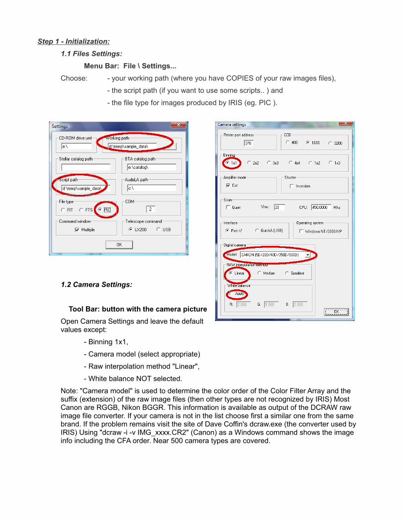
Step 1 - Initialization:1.1 Files Settings:
Menu Bar: File \ Settings... Choose: - your working path (where you have COPIES of your raw images files),
- the script path (if you want to use some scripts.. ) and
- the file type for images produced by IRIS (eg. PIC ).
1.2 Camera Settings:
Tool Bar: button with the camera pictureOpen Camera Settings and leave the default values except:
- Binning 1x1,
- Camera model (select appropriate)
- Raw interpolation method "Linear",
- White balance NOT selected.
Note: "Camera model" is used to determine the color order of the Color Filter Array and the suffix (extension) of the raw image files (then other types are not recognized by IRIS) Most Canon are RGGB, Nikon BGGR. This information is available as output of the DCRAW raw image file converter. If your camera is not in the list choose first a similar one from the same brand. If the problem remains visit the site of Dave Coffin's dcraw.exe (the converter used by IRIS) Using "dcraw -i -v IMG_xxxx.CR2" (Canon) as a Windows command shows the image info including the CFA order. Near 500 camera types are covered.
Step 2 - Checking Images:IRIS has some simple graphical tools that enable us to check images quickly before processing them. This is useful for optimizing the shooting parameters, framing, avoiding saturation... It could be used for further analyzing the images when problems occur.
The raw images can be visualized simply as a CFA / Bayer image using the raw loading:
Menu Bar: File \ Load a RAW file... Slider Box: Auto buttonSlider Box: Range (option)
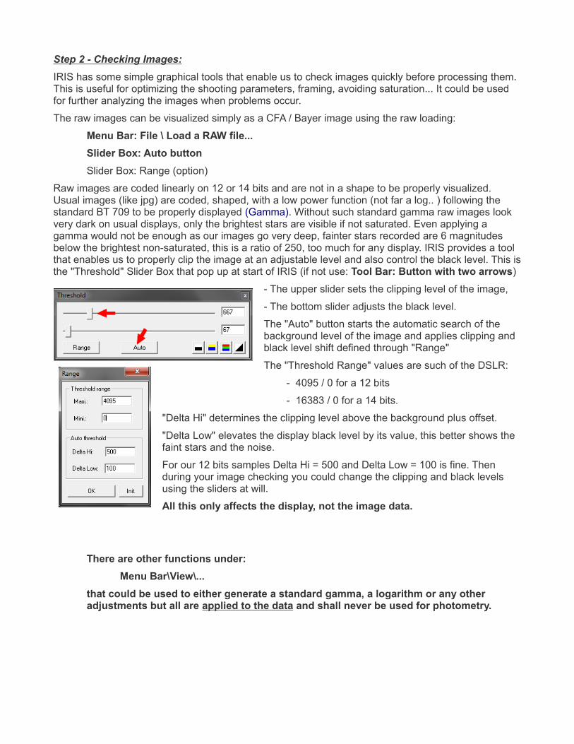
Raw images are coded linearly on 12 or 14 bits and are not in a shape to be properly visualized. Usual images (like jpg) are coded, shaped, with a low power function (not far a log.. ) following the standard BT 709 to be properly displayed (Gamma). Without such standard gamma raw images look very dark on usual displays, only the brightest stars are visible if not saturated. Even applying a gamma would not be enough as our images go very deep, fainter stars recorded are 6 magnitudes below the brightest non-saturated, this is a ratio of 250, too much for any display. IRIS provides a tool that enables us to properly clip the image at an adjustable level and also control the black level. This is the "Threshold" Slider Box that pop up at start of IRIS (if not use: Tool Bar: Button with two arrows)
- The upper slider sets the clipping level of the image,
- The bottom slider adjusts the black level.
The "Auto" button starts the automatic search of the background level of the image and applies clipping and black level shift defined through "Range"
The "Threshold Range" values are such of the DSLR:
- 4095 / 0 for a 12 bits
- 16383 / 0 for a 14 bits.
"Delta Hi" determines the clipping level above the background plus offset.
"Delta Low" elevates the display black level by its value, this better shows the faint stars and the noise.
For our 12 bits samples Delta Hi = 500 and Delta Low = 100 is fine. Then during your image checking you could change the clipping and black levels using the sliders at will.
All this only affects the display, not the image data.
There are other functions under: Menu Bar\View\...
that could be used to either generate a standard gamma, a logarithm or any other adjustments but all are applied to the data and shall never be used for photometry.
2.1 Checking Saturation, Range, Background, Noise...Another simple tool is available through the mouse. If you want to check a star just draw a box around it with the left button down, then click right, a dialog box pops up, click "Statistics" Another box shows you various parameters of interest.
Mouse => draw box => click right => dialog box => Statistics
Saturation check: The "Max" value is such of the highest pixel. With a CCD 12 bits with anti-blooming we should probably not go higher than 2500~3000. In a 14 bits CMOS the sensor would saturate about 14000 ADUs at ISO 100 and then, at higher ISO, the ADC range should clip the image at 16383 ADUs (but much less electrons, limiting the dynamics... )
Background Level: The "Median" value shows it. To get an exact value the box should be drawn in a dark area. Then the "Mean" is a more accurate value. With Canon DSLR that level includes the system offset of the ADC, in general 128 for 12 bits and 1024 for 14 bits.
That value shall be subtracted from the image data to determine the true background level.
Noise level: When used on a dark the "sigma" shows the noise level (Gaussian read noise and possibly some dark current impulse noise) If used on images it could includes some other signals.
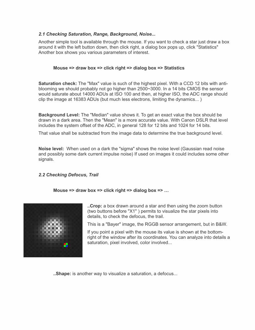
2.2 Checking Defocus, Trail
Mouse => draw box => click right => dialog box => …
..Crop: a box drawn around a star and then using the zoom button (two buttons before "X1" ) permits to visualize the star pixels into details, to check the defocus, the trail.
This is a "Bayer" image, the RGGB sensor arrangement, but in B&W.
If you point a pixel with the mouse its value is shown at the bottom-right of the window after its coordinates. You can analyze into details a saturation, pixel involved, color involved...
..Shape: is another way to visualize a saturation, a defocus...
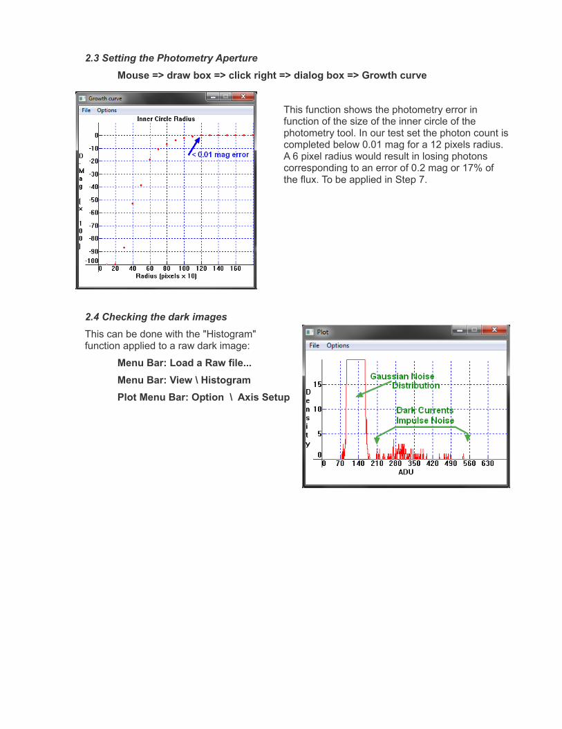
2.3 Setting the Photometry ApertureMouse => draw box => click right => dialog box => Growth curve
This function shows the photometry error in function of the size of the inner circle of the photometry tool. In our test set the photon count is completed below 0.01 mag for a 12 pixels radius. A 6 pixel radius would result in losing photons corresponding to an error of 0.2 mag or 17% of the flux. To be applied in Step 7.
2.4 Checking the dark imagesThis can be done with the "Histogram" function applied to a raw dark image:
Menu Bar: Load a Raw file...Menu Bar: View \ HistogramPlot Menu Bar: Option \ Axis Setup
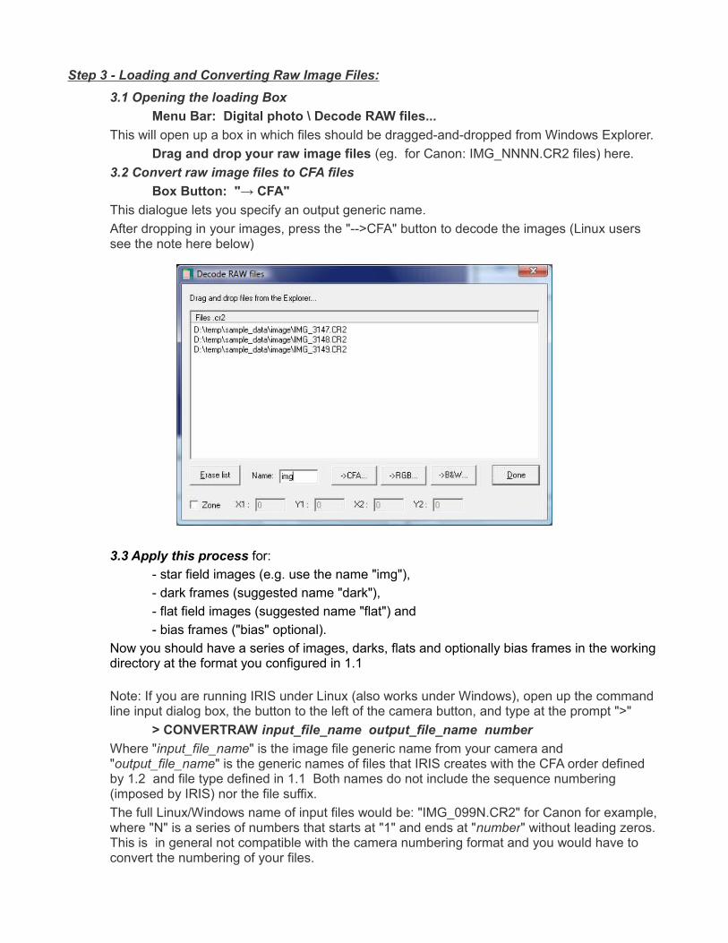
Step 3 - Loading and Converting Raw Image Files:3.1 Opening the loading Box
Menu Bar: Digital photo \ Decode RAW files...This will open up a box in which files should be dragged-and-dropped from Windows Explorer.
Drag and drop your raw image files (eg. for Canon: IMG_NNNN.CR2 files) here. 3.2 Convert raw image files to CFA files
Box Button: "→ CFA"This dialogue lets you specify an output generic name.After dropping in your images, press the "-->CFA" button to decode the images (Linux users see the note here below)
3.3 Apply this process for:- star field images (e.g. use the name "img"),- dark frames (suggested name "dark"),- flat field images (suggested name "flat") and- bias frames ("bias" optional).
Now you should have a series of images, darks, flats and optionally bias frames in the working directory at the format you configured in 1.1
Note: If you are running IRIS under Linux (also works under Windows), open up the command line input dialog box, the button to the left of the camera button, and type at the prompt ">"
> CONVERTRAW input_file_name output_file_name number Where "input_file_name" is the image file generic name from your camera and "output_file_name" is the generic names of files that IRIS creates with the CFA order defined by 1.2 and file type defined in 1.1 Both names do not include the sequence numbering (imposed by IRIS) nor the file suffix. The full Linux/Windows name of input files would be: "IMG_099N.CR2" for Canon for example, where "N" is a series of numbers that starts at "1" and ends at "number" without leading zeros. This is in general not compatible with the camera numbering format and you would have to convert the numbering of your files.
Step 4 - Preprocessing > Bias, Dark, Flat:Unlike CCD cameras, DSLR cameras don't provide the user with the ability to control the sensor temperature and apply a previously computed master dark and bias combination to the images. Because of this, one should take dark shots during the imaging session which will include the bias pattern of the camera. Although the DSLR dark frames will account for the bias, IRIS requires separate bias (offset) frames. Because of this, we can either create a formal bias frame or a fake ("dummy") bias frame, both work equally well, but one of the two must be completed.
As said in Note4 recent sensors have very low differential dark currents and bias pattern, for exposures shorter than 30 sec dark (and in any case bias) can be replaced by dummies.
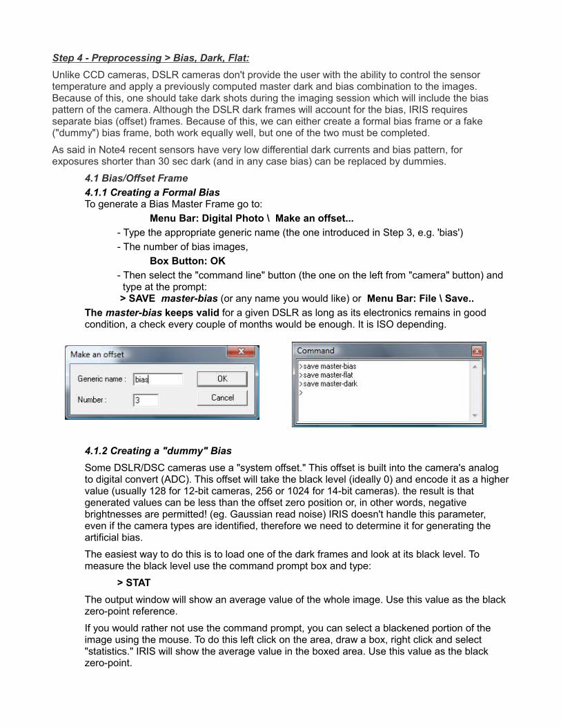
4.1 Bias/Offset Frame4.1.1 Creating a Formal BiasTo generate a Bias Master Frame go to:
Menu Bar: Digital Photo \ Make an offset... - Type the appropriate generic name (the one introduced in Step 3, e.g. 'bias') - The number of bias images,
Box Button: OK- Then select the "command line" button (the one on the left from "camera" button) and type at the prompt: > SAVE master-bias (or any name you would like) or Menu Bar: File \ Save..
The master-bias keeps valid for a given DSLR as long as its electronics remains in good condition, a check every couple of months would be enough. It is ISO depending.
4.1.2 Creating a "dummy" BiasSome DSLR/DSC cameras use a "system offset." This offset is built into the camera's analog to digital convert (ADC). This offset will take the black level (ideally 0) and encode it as a higher value (usually 128 for 12-bit cameras, 256 or 1024 for 14-bit cameras). the result is that generated values can be less than the offset zero position or, in other words, negative brightnesses are permitted! (eg. Gaussian read noise) IRIS doesn't handle this parameter, even if the camera types are identified, therefore we need to determine it for generating the artificial bias.
The easiest way to do this is to load one of the dark frames and look at its black level. To measure the black level use the command prompt box and type:
> STATThe output window will show an average value of the whole image. Use this value as the black zero-point reference.
If you would rather not use the command prompt, you can select a blackened portion of the image using the mouse. To do this left click on the area, draw a box, right click and select "statistics." IRIS will show the average value in the boxed area. Use this value as the black zero-point.
Now we create the artificial bias frame. Use the command prompt box and type:
> FILL valueWhere "value" is the black zero-point from above. Now, save the master bias by typing:
> SAVE master-biasSuch dummy master-bias is valid for ever.
You are done.
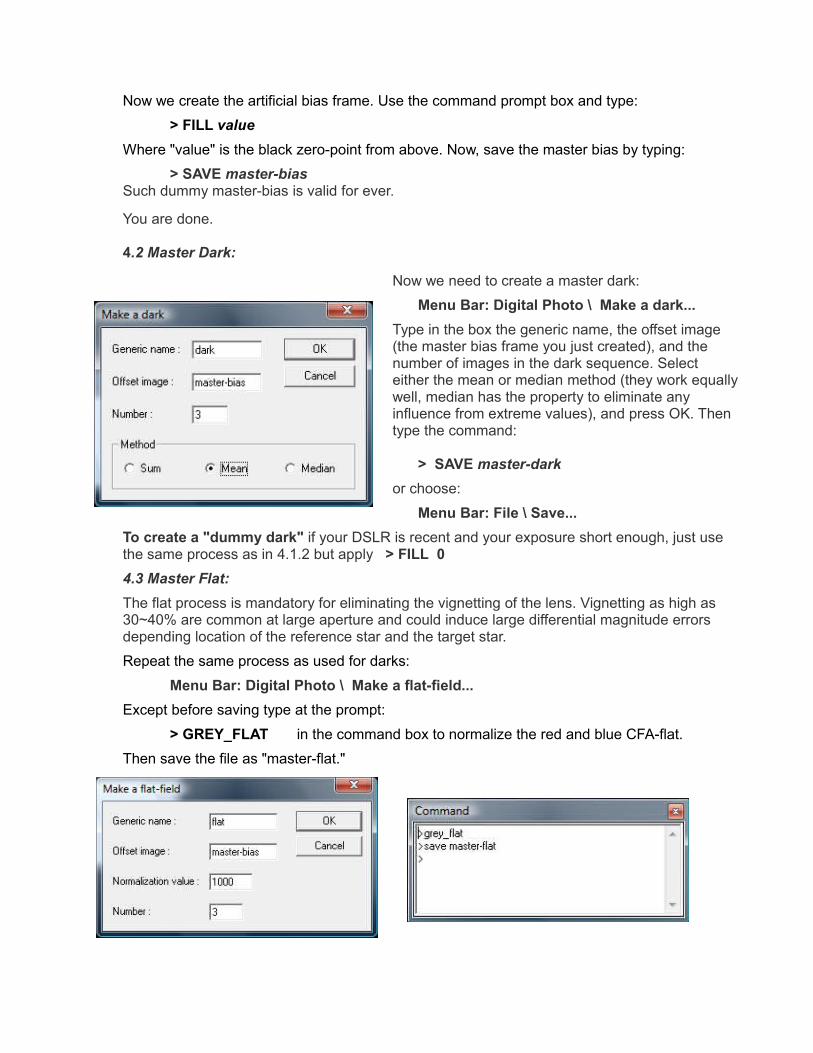
4.2 Master Dark:
Now we need to create a master dark:
Menu Bar: Digital Photo \ Make a dark... Type in the box the generic name, the offset image (the master bias frame you just created), and the number of images in the dark sequence. Select either the mean or median method (they work equally well, median has the property to eliminate any influence from extreme values), and press OK. Then type the command:
> SAVE master-dark
or choose:
Menu Bar: File \ Save...To create a "dummy dark" if your DSLR is recent and your exposure short enough, just use the same process as in 4.1.2 but apply > FILL 04.3 Master Flat:The flat process is mandatory for eliminating the vignetting of the lens. Vignetting as high as 30~40% are common at large aperture and could induce large differential magnitude errors depending location of the reference star and the target star.
Repeat the same process as used for darks:
Menu Bar: Digital Photo \ Make a flat-field...Except before saving type at the prompt:
> GREY_FLAT in the command box to normalize the red and blue CFA-flat.
Then save the file as "master-flat."
That master-flat keeps valid each time you use the same DSLR and Lens at the same aperture, same focus, same focal length for a zoom. Check that no large dust has polluted the low-pass filter that is few millimeters in front of the sensor, this is the only level a dust could be an issue if you use a large lens aperture ( F/4 or less) Any flat would not correct it properly.
4.4 Hot Pixels Detection and Recording:This function automatically detects hot pixels above a threshold level. Such defective pixels couldn't be processed properly through dark or flat. Their coordinates are recorded in a file for further processing of the images (replacement by surrounding average) It might take some experimentation to determine the threshold value you need, but a good starting value at ISO 100 is about 200 ADUs for a 12-bit CCD cameras and 500 for a 14-bit CMOS cameras (offset removed). That threshold should be more or less proportional to the ISO being used. The number of hot pixels could be 50 in the first case or 10 in the second very depending of the sensor quality class.
Load the processed master dark frame (created in Step 4.2 , offset removed by IRIS) and type the following at the command prompt:
> FIND_HOT cosme numberWhere "number" is the threshold value you have selected and "cosme" is the name of the file where the results are recorded (you could chose any you like). Check the Output Box (it should open automatically). If there is a number of hot pixels not detected, change the threshold accordingly.
It's possible to differentiate the random noise, the impulse noise and the hot pixels using the histogram function, the threshold should be well above the Gaussian Noise distribution, then the stack of Dark Impulses and below the isolated peaks on the right corresponding to the hot pixels. You can estimate their number from the graph.
Menu Bar: View \ Histogram (option: adjust the axis to 4000 ADUs or so, density 10 )
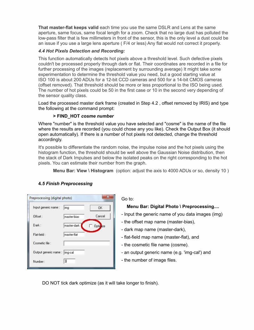
4.5 Finish Preprocessing
Go to:
Menu Bar: Digital Photo \ Preprocessing.... - Input the generic name of you data images (img)
- the offset map name (master-bias),
- dark map name (master-dark),
- flat-field map name (master-flat), and
- the cosmetic file name (cosme).
- an output generic name (e.g. 'img-cal') and
- the number of image files.
DO NOT tick dark optimize (as it will take longer to finish).
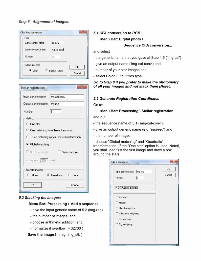
Step 5 - Alignment of Images:
5.1 CFA conversion to RGB:Menu Bar: Digital photo \
Sequence CFA conversion... and select
- the generic name that you gave at Step 4.5 ('img-cal')
- give an output name ('img-cal-conv') and
- number of your star images and
- select Color Output files type .
Go to Step 8 if you prefer to make the photometry of all your images and not stack them (Note6)
5.2 Generate Registration CoordinatesGo to:
Menu Bar: Processing \ Stellar registration and put:
- the sequence name of 5.1 ('img-cal-conv'),
- give an output generic name (e.g. 'img-reg') and
- the number of images
- choose "Global matching" and "Quadratic" transformation (If the "One star" option is used, Note6, you shall load first the first image and draw a box around the star)
5.3 Stacking the images: Menu Bar: Processing \ Add a sequence...
- give the input generic name of 5.2 (img-reg)
- the number of images, and
- choose arithmetic addition, and
- normalize if overflow (> 32700 )
Save the image ! ( eg. img_stk )
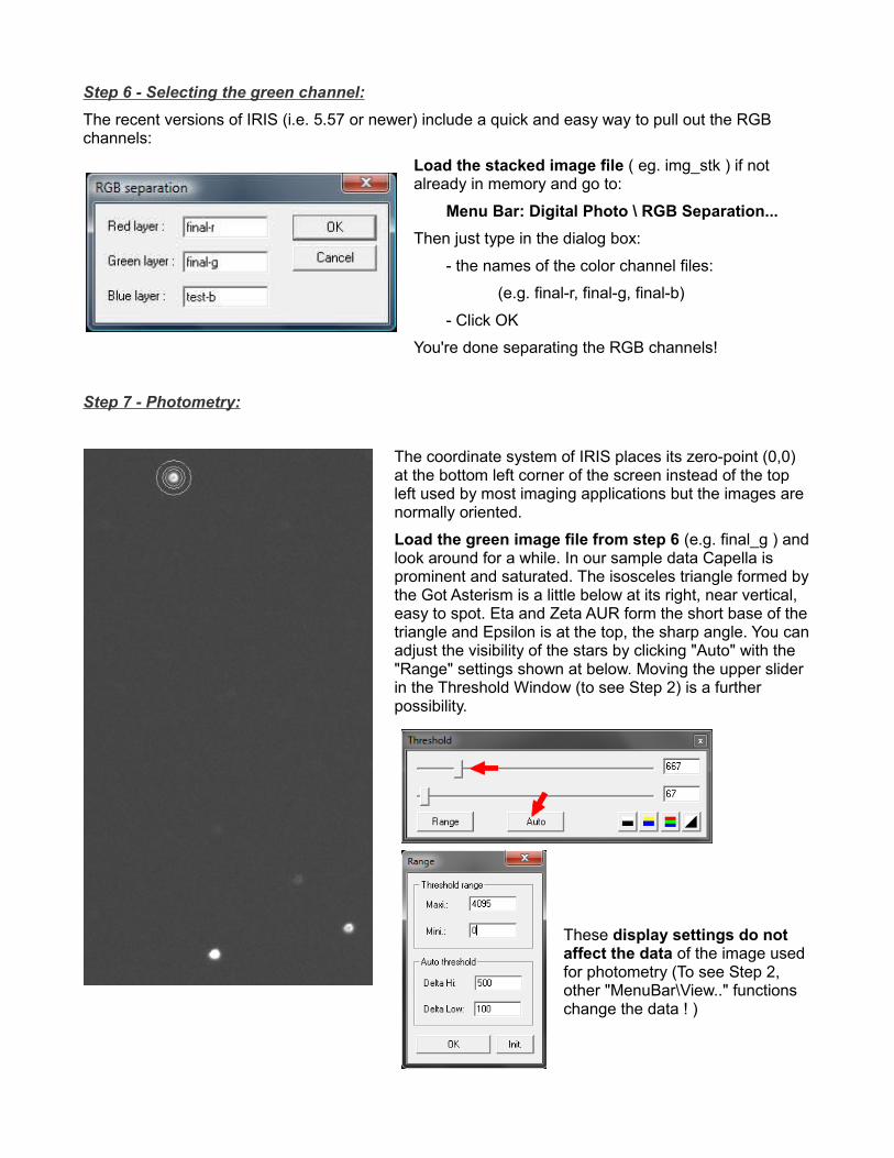
Step 6 - Selecting the green channel:The recent versions of IRIS (i.e. 5.57 or newer) include a quick and easy way to pull out the RGB channels:
Load the stacked image file ( eg. img_stk ) if not already in memory and go to:
Menu Bar: Digital Photo \ RGB Separation...Then just type in the dialog box:
- the names of the color channel files:
(e.g. final-r, final-g, final-b)
- Click OK
You're done separating the RGB channels!
Step 7 - Photometry:
The coordinate system of IRIS places its zero-point (0,0) at the bottom left corner of the screen instead of the top left used by most imaging applications but the images are normally oriented.
Load the green image file from step 6 (e.g. final_g ) and look around for a while. In our sample data Capella is prominent and saturated. The isosceles triangle formed by the Got Asterism is a little below at its right, near vertical, easy to spot. Eta and Zeta AUR form the short base of the triangle and Epsilon is at the top, the sharp angle. You can adjust the visibility of the stars by clicking "Auto" with the "Range" settings shown at below. Moving the upper slider in the Threshold Window (to see Step 2) is a further possibility.
These display settings do not affect the data of the image used for photometry (To see Step 2, other "MenuBar\View.." functions change the data ! )
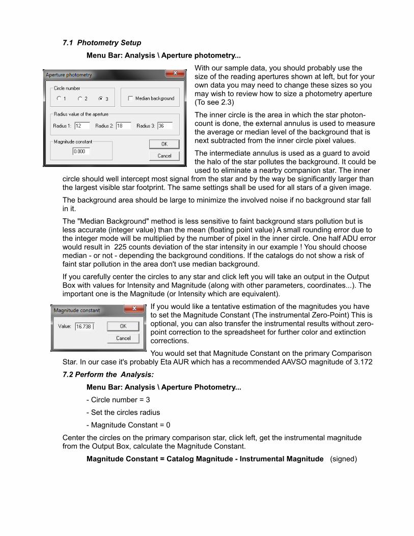
7.1 Photometry SetupMenu Bar: Analysis \ Aperture photometry...
With our sample data, you should probably use the size of the reading apertures shown at left, but for your own data you may need to change these sizes so you may wish to review how to size a photometry aperture (To see 2.3)
The inner circle is the area in which the star photon-count is done, the external annulus is used to measure the average or median level of the background that is next subtracted from the inner circle pixel values.
The intermediate annulus is used as a guard to avoid the halo of the star pollutes the background. It could be used to eliminate a nearby companion star. The inner
circle should well intercept most signal from the star and by the way be significantly larger than the largest visible star footprint. The same settings shall be used for all stars of a given image.
The background area should be large to minimize the involved noise if no background star fall in it.
The "Median Background" method is less sensitive to faint background stars pollution but is less accurate (integer value) than the mean (floating point value) A small rounding error due to the integer mode will be multiplied by the number of pixel in the inner circle. One half ADU error would result in 225 counts deviation of the star intensity in our example ! You should choose median - or not - depending the background conditions. If the catalogs do not show a risk of faint star pollution in the area don't use median background.
If you carefully center the circles to any star and click left you will take an output in the Output Box with values for Intensity and Magnitude (along with other parameters, coordinates...). The important one is the Magnitude (or Intensity which are equivalent).
If you would like a tentative estimation of the magnitudes you have to set the Magnitude Constant (The instrumental Zero-Point) This is optional, you can also transfer the instrumental results without zero-point correction to the spreadsheet for further color and extinction corrections.
You would set that Magnitude Constant on the primary Comparison Star. In our case it's probably Eta AUR which has a recommended AAVSO magnitude of 3.172
7.2 Perform the Analysis:Menu Bar: Analysis \ Aperture Photometry...- Circle number = 3
- Set the circles radius
- Magnitude Constant = 0
Center the circles on the primary comparison star, click left, get the instrumental magnitude from the Output Box, calculate the Magnitude Constant.
Magnitude Constant = Catalog Magnitude - Instrumental Magnitude (signed)
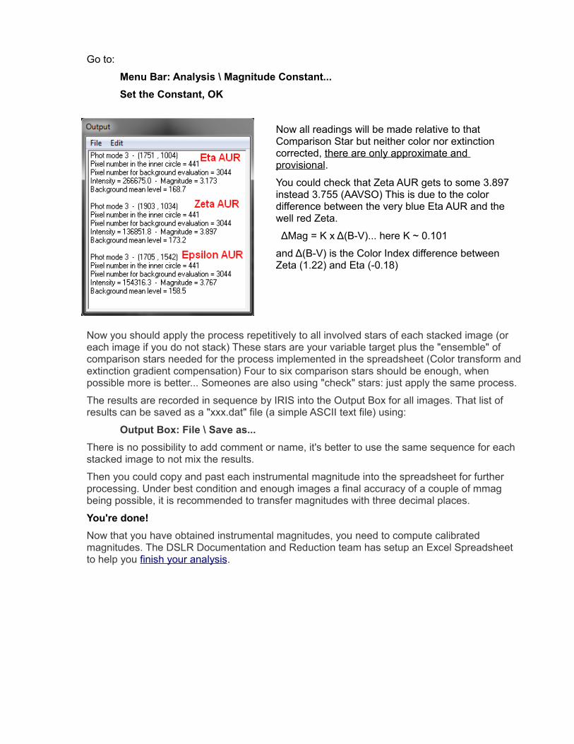
Go to:
Menu Bar: Analysis \ Magnitude Constant...Set the Constant, OK
Now all readings will be made relative to that Comparison Star but neither color nor extinction corrected, there are only approximate and provisional.
You could check that Zeta AUR gets to some 3.897 instead 3.755 (AAVSO) This is due to the color difference between the very blue Eta AUR and the well red Zeta.
ΔMag = K x Δ(B-V)... here K ~ 0.101
and Δ(B-V) is the Color Index difference between Zeta (1.22) and Eta (-0.18)
Now you should apply the process repetitively to all involved stars of each stacked image (or each image if you do not stack) These stars are your variable target plus the "ensemble" of comparison stars needed for the process implemented in the spreadsheet (Color transform and extinction gradient compensation) Four to six comparison stars should be enough, when possible more is better... Someones are also using "check" stars: just apply the same process.
The results are recorded in sequence by IRIS into the Output Box for all images. That list of results can be saved as a "xxx.dat" file (a simple ASCII text file) using:
Output Box: File \ Save as...There is no possibility to add comment or name, it's better to use the same sequence for each stacked image to not mix the results.
Then you could copy and past each instrumental magnitude into the spreadsheet for further processing. Under best condition and enough images a final accuracy of a couple of mmag being possible, it is recommended to transfer magnitudes with three decimal places.
You're done!Now that you have obtained instrumental magnitudes, you need to compute calibrated magnitudes. The DSLR Documentation and Reduction team has setup an Excel Spreadsheet to help you finish your analysis.
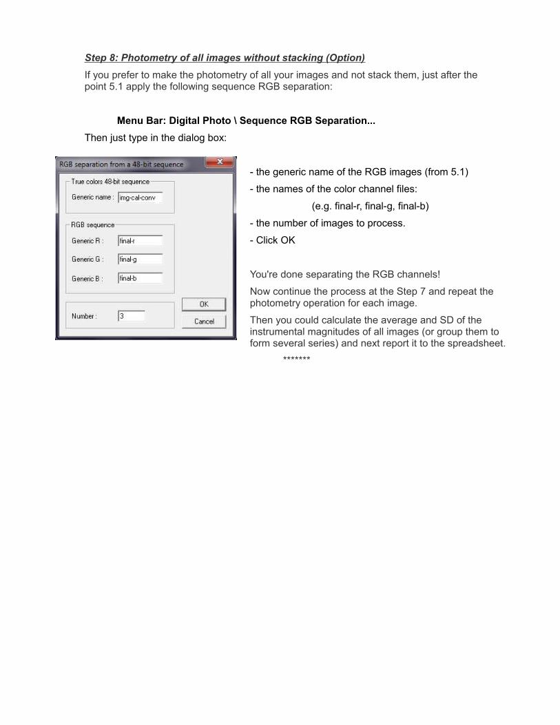
Step 8: Photometry of all images without stacking (Option)If you prefer to make the photometry of all your images and not stack them, just after the point 5.1 apply the following sequence RGB separation:
Menu Bar: Digital Photo \ Sequence RGB Separation...Then just type in the dialog box:
- the generic name of the RGB images (from 5.1)
- the names of the color channel files:
(e.g. final-r, final-g, final-b)
- the number of images to process.
- Click OK
You're done separating the RGB channels!
Now continue the process at the Step 7 and repeat the photometry operation for each image.
Then you could calculate the average and SD of the instrumental magnitudes of all images (or group them to form several series) and next report it to the spreadsheet.
*******