iridium manual version 1.2 - international civil aviation ... working groups... · web vieweach...
TRANSCRIPT

ICAO TECHNICAL MANUAL FOR
IRIDIUM
AERONAUTICAL MOBILE SATELLITE (ROUTE) SERVICE
DRAFT v1.120
1974 May August 2006

Date &Version Change
9/20/05 v0.1 Draft WP-05 submitted for ACP-WGM-IRD-SWG01
11/1/05 v0.2 Draft WP-02 submitted for ACP-WGM-IRD-SWG02 with input from IRD-SWG01
2/15/06 v0.3 Draft WP-05 submitted for ACP-WGM-IRD-SWG03 with input from IRD-SWG02
5/17/06 v1.0 Draft WP-04 submitted for ACP-WGM-IRD-SWG04 with input from IRD-SWG03
5/19/06 v1.1 Draft with input from ACP-WGM-IRD-SWG04
v1.2 TJ

Table of ContentsMANUAL FOR ................................................................................................................................IIRIDIUM ..........................................................................................................................................I
AERONAUTICAL MOBILE SATELLITE (ROUTE) SERVICE ..........................................iDRAFT V1.2 ....................................................................................................................................I4 AUGUST 2006 ..............................................................................................................................I1 INTRODUCTION ...................................................................................................................1
1.1 Objective ..........................................................................................................................11.2 Scope ................................................................................................................................11.3 Background ......................................................................................................................1
2 SERVICES, USER REQUIREMENTS AND OPERATIONAL BENEFITS ........................42.1 Operational services .........................................................................................................4
2.1.1 General .....................................................................................................................42.1.2 Air traffic services (ATS) ........................................................................................62.1.3 Aeronautical operational control (AOC) .................................................................72.1.4 Non-safety services ..................................................................................................7
2.2 User requirements ............................................................................................................72.2.1 Minimum available throughput ...............................................................................7
1

2.2.2 Maximum transit delay ............................................................................................82.2.3 Priority .....................................................................................................................82.2.4 Reliability/integrity ..................................................................................................82.2.5 Protection .................................................................................................................92.2.6 Minimum area of connectivity .................................................................................92.2.7 Cost/benefit ............................................................................................................102.2.8 Interoperability ......................................................................................................10
2.3 Anticipated operational benefits ....................................................................................102.3.1 General ...................................................................................................................102.3.2 Benefits on oceanic scenario .................................................................................102.3.3 ADS message handling function ...........................................................................112.3.4 Two way data link communications function ........................................................112.3.5 Digital voice communications ...............................................................................11
2.4 Operational scenarios .....................................................................................................122.4.1 High air traffic density oceanic areas ....................................................................122.4.2 Low air traffic density oceanic/continental en route areas ....................................122.4.3 High air traffic density continental en route areas .................................................132.4.4 Terminal areas .......................................................................................................13
2

3 STANDARDIZATION ACTIVITIES ..................................................................................153.1 AMS(R)S system operator specifications ......................................................................153.2 AEEC and ARINC Characteristics ................................................................................153.3 Minimum operational performance standards (MOPS) ................................................163.4 Satellite system access approval ....................................................................................163.5 Avionics and certification ..............................................................................................16
3.5.1 Avionics .................................................................................................................163.5.2 Airworthiness certification ....................................................................................163.5.3 Type acceptance .....................................................................................................173.5.4 Licensing and permits ............................................................................................173.5.5 Service providers ...................................................................................................17
4 ICAO ACTIVITIES ...............................................................................................................174.1 Institutional arrangements .............................................................................................174.2 AMS(R) spectrum availability .......................................................................................224.3 Standards and Recommended Practices (SARPs) .........................................................224.4 Future developments ......................................................................................................22
5 IRIDIUM SATELLITE NETWORK ...................................................................................235.1 Overview ........................................................................................................................23
3

5.2 System Architecture .......................................................................................................245.2.1 Space Segment .......................................................................................................255.2.2 Terrestrial Segment ................................................................................................27
5.3 Channel Classifications .................................................................................................285.3.1 Overhead Channels ................................................................................................285.3.2 Bearer Service Channels ........................................................................................29
5.4 Channel Multiplexing ....................................................................................................295.4.1 TDMA Frame Structure .........................................................................................305.4.2 FDMA Frequency Plan ..........................................................................................305.4.3 Duplex Channel Band ............................................................................................305.4.4 Simplex Channel Band ..........................................................................................32
5.5 L-Band (1616-1626.5 MHz) Transmission Characteristics ...........................................335.5.1 Signal Format .........................................................................................................335.5.2 Power Control ........................................................................................................34
5.6 Call Processing ..............................................................................................................345.6.1 Acquisition .............................................................................................................345.6.2 Access ....................................................................................................................365.6.3 Registration and Auto-Registration .......................................................................36
4

5.6.4 Telephony ..............................................................................................................375.6.5 Handoff ..................................................................................................................38
5.7 Voice and Data Traffic Channel ....................................................................................395.8 Iridium Data Services – RUDICS and SBD ..................................................................40
5.8.1 Iridium RUDICS Service .......................................................................................405.8.2 Iridium SBD Service ..............................................................................................42
6 IRIDIUM AMS(R)S SYSTEM .............................................................................................456.1 System overview ............................................................................................................456.2 System elements ............................................................................................................45
6.2.1 Aircraft Earth Station .............................................................................................456.2.2 Space segment .......................................................................................................456.2.3 Ground Earth Station .............................................................................................46
7 IRIDIUM AMS(R)S STANDARDIZATION ACTIVITIES ................................................467.1 IRDIUM Air Interface Specifications ...........................................................................467.2 AEEC and ARINC Characteristics ................................................................................467.3 Minimum operational performance standards (MOPS) ................................................467.4 Satellite system access approval ....................................................................................467.5 Avionics and certification ..............................................................................................47
5
7.5.1 Avionics .................................................................................................................477.5.2 Airworthiness certification ....................................................................................477.5.3 Type acceptance .....................................................................................................477.5.4 Licensing and permits ............................................................................................477.5.5 Service providers ...................................................................................................47
8 COMPARISON OF AMS(R)S SARPS AND EXPECTED IRIDIUM PERFORMANCE . .478.1 RF Characteristics ..........................................................................................................48
8.1.1 Frequency Bands ...................................................................................................488.1.2 Emissions ...............................................................................................................488.1.3 Susceptibility .........................................................................................................49
8.2 Priority and Preemptive Access .....................................................................................498.3 Signal Acquisition and Tracking ...................................................................................508.4 Performance Requirements ............................................................................................52
8.4.1 Designated Operational Coverage .........................................................................528.4.2 Failure Notification ................................................................................................528.4.3 AES Requirements .................................................................................................538.4.4 Packet Data Service Performance ..........................................................................538.4.5 Voice Service Performance ...................................................................................56
6

8.4.6 Security ..................................................................................................................578.5 System Interfaces ...........................................................................................................58
9 IMPLEMENTATION GUIDANCE ......................................................................................659.1 THEORY OF OPERATION .........................................................................................659.2 SERVICES SUPPORTED .............................................................................................659.3 OPERATION .................................................................................................................659.4 AVIONICS ....................................................................................................................659.5 FUTURE SERVICES ....................................................................................................65
APPENDIX A: AIRCRAFT EARTH STATION RF CHARACTERISTICS ..............................66APPENDIX B: ATN OVERVIEW ...............................................................................................70TBD. ..............................................................................................................................................70APPENDIX C: ACRONYMS .......................................................................................................70
1 INTRODUCTION ..........................................................................................................................1.1 SCOPE .......................................................................................................................................21.2 IRIDIUM AMS(R)S ..................................................................................................................21.3 APPLICABLE DOCUMENTS .................................................................................................32 IRIDIUM SATELLITE NETWORK OVERVIEW .....................................................................5
7
2.1 SYSTEM ARCHITECTURE ....................................................................................................52.1.1 SPACE SEGMENT ................................................................................................................62.1.2 TERRESTRIAL SEGMENT ..................................................................................................82.2 CHANNEL CLASSIFICATIONS .............................................................................................82.2.1 OVERHEAD CHANNELS ....................................................................................................92.2.2 BEARER SERVICE CHANNELS .......................................................................................102.3 CHANNEL MULTIPLEXING ...............................................................................................102.3.1 TDMA FRAME STRUCTURE ...........................................................................................102.3.2 FDMA FREQUENCY PLAN ..............................................................................................112.3.3 DUPLEX CHANNEL BAND ..............................................................................................112.3.4 SIMPLEX CHANNEL BAND .............................................................................................132.4 L-BAND (1616-1626.5 MHZ) TRANSMISSION CHARACTERISTICS ............................142.4.1 SIGNAL FORMAT ..............................................................................................................142.4.2 POWER CONTROL ............................................................................................................152.5 CALL PROCESSING .............................................................................................................152.5.1 ACQUISITION .....................................................................................................................152.5.2 ACCESS ...............................................................................................................................172.5.3 REGISTRATION AND AUTO-REGISTRATION .............................................................17
8

2.5.4 TELEPHONY .......................................................................................................................182.5.5 HANDOFF ...........................................................................................................................192.6 VOICE AND DATA TRAFFIC CHANNEL ..........................................................................202.7 IRIDIUM DATA SERVICES – RUDICS AND SBD ............................................................212.7.1 IRIDIUM RUDICS SERVICE .............................................................................................212.7.2 IRIDIUM SBD SERVICE ....................................................................................................233 AMS(R)S SARPS COMPLIANCE ............................................................................................253.1 RF CHARACTERISTICS .......................................................................................................253.1.1 FREQUENCY BANDS ........................................................................................................253.1.2 EMISSIONS .........................................................................................................................253.1.3 SUSCEPTIBILITY ...............................................................................................................263.2 PRIORITY AND PREEMPTIVE ACCESS ...........................................................................263.3 SIGNAL ACQUISITION AND TRACKING .........................................................................273.4 PERFORMANCE REQUIREMENTS ....................................................................................283.4.1 DESIGNATED OPERATIONAL COVERAGE .................................................................283.4.2 FAILURE NOTIFICATION ................................................................................................283.4.3 AES REQUIREMENTS .......................................................................................................293.4.4 PACKET DATA SERVICE PERFORMANCE ..................................................................29
9

3.4.5 VOICE SERVICE PERFORMANCE ..................................................................................313.4.6 SECURITY ...........................................................................................................................323.5 SYSTEM INTERFACES ........................................................................................................33APPENDIX A: AIRCRAFT EARTH STATION RF CHARACTERISTICS ..............................39APPENDIX B: ACRONYMS .......................................................................................................43
1 INTRODUCTION ........................................................................................................................11.1 SCOPE .......................................................................................................................................11.2 IRIDIUM AMS(R)S ..................................................................................................................21.3 APPLICABLE DOCUMENTS .................................................................................................32 IRIDIUM COMMUNICATION SYSTEM OVERVIEW ...........................................................52.1 SYSTEM ARCHITECTURE ....................................................................................................52.1.1 SPACE SEGMENT ................................................................................................................62.1.2 TERRESTRIAL SEGMENT ..................................................................................................82.2 CHANNEL CLASSIFICATIONS .............................................................................................82.2.1 OVERHEAD CHANNELS ....................................................................................................92.2.2 BEARER SERVICE CHANNELS .......................................................................................102.3 CHANNEL MULTIPLEXING ...............................................................................................10
10
2.3.1 TDMA FRAME STRUCTURE ...........................................................................................102.3.2 FDMA FREQUENCY PLAN ..............................................................................................112.3.3 DUPLEX CHANNEL BAND ..............................................................................................112.3.4 SIMPLEX CHANNEL BAND .............................................................................................132.4 SUBSCRIBER LINK TRANSMISSION CHARACTERISTICS ..........................................142.4.1 SIGNAL FORMAT ..............................................................................................................142.4.2 POWER CONTROL ............................................................................................................152.5 CALL PROCESSING .............................................................................................................152.5.1 ACQUISITION .....................................................................................................................152.5.2 ACCESS ...............................................................................................................................172.5.3 REGISTRATION AND AUTO-REGISTRATION .............................................................172.5.4 TELEPHONY .......................................................................................................................182.5.5 HANDOFF ...........................................................................................................................192.6 VOICE AND DATA TRAFFIC CHANNEL ..........................................................................202.7 IRIDIUM DATA SERVICES – RUDICS AND SBD ............................................................212.7.1 IRIDIUM RUDICS SERVICE .............................................................................................212.7.2 IRIDIUM SBD SERVICE ....................................................................................................233 AMS(R)S SARPS COMPLIANCE ............................................................................................25
11

3.1 RF CHARACTERISTICS .......................................................................................................253.1.1 FREQUENCY BANDS ........................................................................................................253.1.2 EMISSIONS .........................................................................................................................253.1.3 SUSCEPTIBILITY ...............................................................................................................263.2 PRIORITY AND PREEMPTIVE ACCESS ...........................................................................263.3 SIGNAL ACQUISITION AND TRACKING .........................................................................273.4 PERFORMANCE REQUIREMENTS ....................................................................................283.4.1 DESIGNATED OPERATIONAL COVERAGE .................................................................283.4.2 FAILURE NOTIFICATION ................................................................................................283.4.3 AES REQUIREMENTS .......................................................................................................293.4.4 PACKET DATA SERVICE PERFORMANCE ..................................................................293.4.5 VOICE SERVICE PERFORMANCE ..................................................................................313.4.6 SECURITY ...........................................................................................................................323.5 SYSTEM INTERFACES ........................................................................................................34APPENDIX A: AIRCRAFT EARTH STATION RF CHARACTERISTICS ..............................39Appendix B: ACRONYMS ...........................................................................................................43
12

1 INTRODUCTION
1.1 O bjectiveThe objective of this technical manual is to provide guidance to ICAO Contracting States, and to the international civil aviation community, on their consideration of the Iridium Satellite Network as a platform to offer aeronautical mobile satellite (route) service (AMS(R)S).
1.2 ScopeThis manual contains information about aeronautical mobile satellite communications, using the Iridium Satellite Network, including applications, potential benefits, user requirements, system architecture, interoperability and technical characteristics, as well as space, ground and airborne equipment. Information on status of development and ICAO activities is also included.
Chapter 1 of this document describes some potential benefits that can be expected from the use of a satellite communication service for AMS(R)S. In addition, it provides an overview of how Iridium Satellite Network can support AMS(R)S.
1

Chapter 2 contains a generic description of a satellite communication system configuration including ground subnetworks, the Iridium Satellite subnetwork of which the Aircraft Earth Station (AES) is one part, and the aircraft subnetworks.
Chapter 3 is an informative section containing information provided by Iridium Satellite LLC on their compliance with ICAO AMS(R)S SARPs. Appendix A provides information on Iridium specific performance parameters pertaining to minimum operation performance standard for avionics supporting next generation satellite system as specified in RTCA DO-262.
Given that the performance of the future Iridium AMS(R)S system will highly depend on the performance of the underlying Iridium satellite subnetwork, we believe that this technical manual will provide valuable insight as guidance material of the performance of the future Iridium AMS(R)S system.
It is not the objective of this technical manual to serve as a verification report. Once the end-to-end Iridium AMS(R)S is designed, built, and tested, ISLLC, its AMS(R)S service providers, and its avionics manufacturers will submit certification and regulatory type approval material to Civil Aviation Administrator and other regulatory agencies of individual State for Iridium AMS(R)S certification.
2

1.3 BackgroundThe ICAO Aeronautical Communications Panel (ACP) has carried forward the future air navigation systems planning that designated basic architectural concepts for using satellite communications, initially in oceanic and remote environments, and eventually in continental airspace. The progress toward satellite communications for aeronautical safety is realized through the preparation of Standards and Recommended Practices (SARPs) and guidance material by ICAO, and through the interactions of ICAO with other international bodies to assure that resources are coordinated and available.
Acceptance of the applicability of data links to air traffic services (ATS) as largely replacing voice communications has led planners to assure that all elements of system improvement are coordinated and broadly interoperable. The Aeronautical Mobile Satellite (Route) Service (AMS(R)S) provides a crucial part of the planned over all data network, called the aeronautical telecommunications network (ATN) which will provide end to end connectivity among computers used to support aircraft operations, including computers installed in aircraft. This network, developed and planned by ICAO, includes for example VHF data link subnetwork
3
traffic for exchanging data where line of sight communications with aircraft is practical. The ATN is designed to carry packet data, providing rapid, efficient routing of user data related to safety and regularity of flight.
AMS(R)S systems comprises one of the subnetworks of the ATN. Interoperability between the various subnetworks is assured by means of standardized architecture for all elements, based on ICAO SARPs and guidance material.
Increased functional requirements in the flightdeck, together with the ever present needs to improve operational reliability, economy, and improved safety, are driving more and more avionics systems toward all digital implementations. AMS(R)S is a part of this revolution, providing automatic communications for ATS and aeronautical operational communications (AOC) to support reduction of the workload while improving operations.
AES implementation standardization will be assured by standards, co ordinated test plans and procedures under minimum operational performance standards (MOPS) under development by the Radio Technical Commission on Aeronautics (RTCA) and counterpart minimum operational performance specifications (MPS), developed and coordinated by the European Organization for Civil Aviation Electronics (EUROCAE).
4

Key technologies available only in the last few years at reasonable costs include small and effective aircraft antennae to link with the satellite electronics. While the ground earth stations are the end points for the AMS(R)S, the actual user communications can extend far beyond, going from the aircraft through the ATN to host computers and their terminals, and to voice users through the terrestrial telephone networks.
The sharing concept also may optionally include the AES with voice and data connections through an on board switching system to the cabin. This will permit services that could be attractive to airline passengers while using the same avionics equipment. Safety communications are assured of always having the highest priority, and will be available rapidly when needed.
The communications transactions will be arranged through contracts with the satellite and ground service providers. The avionics will be procured and installed by aircraft owners, while the satellite and ground earth stations initially will be operated commercially. Their services may be offered on various short and long term bases.
The use of satellite telecommunications for aeronautical communication service is an emerging technology. The current aeronautical communication systems are primarily High Frequency (HF), Very High Frequency (VHF) radio links to ground stations. Systems using these radio
5

links have been traditionally known as Aeronautical Mobile Services (AMS) in general. When used in commercial aircraft, the services are identified with the term “Route”, usually by adding “(R)” to the acronym, indicating that the services apply to air traffic in the commercial air routes. The term “Off Route” applies to military aircraft, which do not fly in the commercial air lanes. The term AM(R)S thus refers to aeronautical mobile communications in the commercial air routes. The addition of the term “Satellite” refers to the emerging use of Satellite Communications for aeronautical communications, hence Aeronautical Mobile-Satellite (R) Service, AMS(R)S.
Satellite communications fit into the current radio link infrastructure because they provide services that traditional radio link communications cannot provide reliably. Excluding the possibility of “bouncing” HF signals off of the ionosphere, traditional radio communications are “line of sight” which limits aeronautical communications to a range of approximately 500 km even over “flat” terrain such as the ocean. Currently commercial air carriers are using satellite communications to provide AMS(R)S services in areas not covered by radio communications such as transoceanic flights. The present AMS(R)S technology is dependent on a geosynchronous satellite communications infrastructure which can only be accessed at lower latitudes (<70 degrees).
6

Iridium Communication SystemIridium Satellite Network (ICS), with its constellation of 66 low Earth orbit (LEO) satellites, is the only global mobile satellite communication network in the world, with complete coverage of the entire Earth, including oceans, airways, and Polar regions, offering reliable voice and data service to and from remote areas where no other form of communication is available. Iridium Communication SystemIridium Satellite Network is well suited for AMS(R)S offering capabilities where no other communication systems in the world provide.
Back in the late ‘90s, Iridium and its business partners were involved in various ICAO Working Groups dialoguing with working group members and assessing the acceptability of ICSIridium Satellite Network for AMS(R)S offering. The consensus was that Iridium met the Acceptability Criteria of AMS(R)S offering after AMCP WGA/14 and WP-599 submission in January 1999. This was before the AMS(R)S SARPs was written and was before the launch of the Iridium commercial service.
Now in its sixth year of successful operation with hundreds of thousands of subscribers all over the world and its user terminals installed on numerous type of aircrafts, Iridium Satellite LLC, the new Iridium company, is working with its service providers and aircraft equipment manufacturers in planning for the Iridium AMS(R)S offering. Iridium Satellite LLC is also
7

working with ICAO and its working groups to ensure the future Iridium AMS(R)S offering is in compliance with the newly drafted AMS(R)S SARPs.
Scope
The objective of this technical manual is to provide guidance to States on their consideration of the Iridium Communication SystemIridium Satellite Network as a platform to offer AMS(R)S. The scope of this document contains the Iridium service provider portion of an end-to-end AMS(R)S system. This document is also reflectss the change in ICAO policy, as decided in the last assembly meeting (reference), to have a performance based SARPs as compared to an implementation based SARPs.
Chapter 1 of this document provides an overview of how Iridium Communication SystemIridium Satellite Network can support AMS(R)S. It is followed by a system overview of the ICSIridium Satellite Network in Chapter 2. Chapter 3 provides ICSIridium Satellite Network performance information in light of the AMS(R)S SARPs. Appendix A provides a table of Iridium specific performance parameters pertaining to minimum operation performance standard for avionics supporting next generation satellite system as specified in RTCA DO-262.
8

Given that the performance of the future Iridium AMS(R)S system will highly depend on the performance of the underlying Iridium satellite subnetwork, we believe that this technical manual will provide valuable insight as guidance material of the performance of the future Iridium AMS(R)S system.
It is not the objective of this technical manual to serve as a verification report. Once the end-to-end Iridium AMS(R)S is designed, built, and tested, ISLLC, its aeronauticalAMS(R)S service providers, and its AMS(R)S avionics manufacturers will submit certification and regulatory type approval material to Civil Aviation Administrator and other regulatory agencies of individual State for Iridium AMS(R)S certification.
2 Services, user requirements and operational benefits
2.1 Operational services
2.1.1 GeneralAir traffic scenarios in various parts of the world widely differ, and are likely to do so in the future. Global systems must therefore be able to deal with diverse air traffic densities and types
9

of aircraft, with vastly different performances and equipment fit; these variations, however, must not lead to an undue variety of diversified avionic and ground segments.
In general, as new communication, navigation and surveillance systems will provide for closer interaction between the ground and airborne systems before and during flight, air traffic management will allow for a more flexible and efficient use of the airspace and, thus, enhance air traffic capacity.
Aeronautical communication services are classified as:
a) safety communications requiring high integrity and rapid response:
1) safety-related communications carried out by the air traffic services (ATS) for air traffic control (ATC), flight information and alerting; and
2) communications carried out by aircraft operators, which also affect air transport safety, regularity and efficiency (aeronautical operational control (AOC)); and
b) non-safety related communications:
10

1) private correspondence of aeronautical operators (aeronautical administrative communications (AAC)); and
2) public correspondence (aeronautical passenger communications (APC)).
2.1.1.1 Data communicationSince the earliest days of air traffic control, air ground communication between the flight crew and the air traffic controller has been by means of speech over radiotelephony on either HF or VHF. When radiotelephony channels become congested or during HF propagation disturbances, communication reliability can decrease to a point where flight safety and efficiency may be affected.
Despite the introduction of Secondary Surveillance Radar (SSR) which includes limited air to ground data transfer providing controller workload relief in terms of altitude verification and aircraft identification, the burden of voice communication is still high. Moreover large areas of the world lay beyond the coverage of land based radars. In those remote areas, both tactical communication and position reports must be passed over variable quality and unreliable HF circuits.
11

Experience has shown that alleviation of these shortcomings is limited by other factors on the ground. In particular the saturation of manual air traffic control capabilities creates strong pressures for automated assistance in air traffic services and increasing levels of automation are being incorporated in aircraft systems. If their full potential benefits are to be achieved, there is a clear need to handle an increased information flow between them. A digital data link is thus deemed to be an essential element of any advanced automated air traffic control environment.
It is currently envisaged that future air traffic management systems will increasingly make use of various physical links (VHF, satellites) to allow for the automatic transmission of data from air to ground and vice versa. An efficient use of these data implies that their supporting services will have a universal value. It is therefore to the advantage of every provider and user to foster international standardization.
Many useful safety related applications may be implemented. One outstanding safety factor in the use of a digital data link will, e.g. be the avoidance of garbled or misinterpreted information. In order to be used for safety related services, an air ground data link must have high integrity.
12

2.1.1.2 Voice communicationWhereas, the increase of automatic exchange between air and ground systems is expected, the use of voice communication will still be imperative. Emergencies and non routine problems, as well as some urgent negotiations between pilot and controller make voice communications a continuing requirement.
Aeronautical mobile services in continental areas, where limitations of line of sight so permit, will continue to use VHF. Oceanic and other remote areas at present rely on HF, which may imply the need for communication operators between pilots and controllers.
The only viable solution to overcome the limitations and shortcomings in the ATS and AOC voice communications is the application of satellite based communication systems.
2.1.2 A ir traffic services (ATS)
2.1.2.1 Air traffic control services (ATC)tbd
13

2.1.2.2 Automated downlink of airborne parameter servicesThe automated downlink of information available in the aircraft will support safety. Such service may, for example, help to detect inconsistencies between ATC used flight plans and the one activated in the aircraft’s flight management system (FMS). Enhancement to existing surveillance functions on the ground can be expected by downlinking of specific tactical flight information such as current indicated heading, air speed, vertical rate of climb or descent, and wind vector.
2.1.2.3 Flight information services (FIS)Flight information services provide flight crews with compiled meteorological and operational flight information specifically relevant to the departure, approach and landing phases of flight.
2.1.2.4 Alerting servicesThe objective of the alerting service is to enable flight crews to notify appropriate ground authorities when the aircraft is in a state of emergency or abnormal situation.
14

2.1.2.5 Automated dependent surveillance (ADS)The introduction of satellite communication technology, together with sufficiently accurate and reliable aircraft navigation, e.g. by GNSS, present ample opportunity to provide better surveillance services mostly in areas where such services lack efficiency: in particular over oceanic areas and other areas where the current systems (i.e. radars) prove difficult, uneconomic, or even impossible to implement.
ADS is an application whereby the information generated by an aircraft on board navigation system is automatically relayed from the aircraft, via a satellite data link, to the air traffic services and displayed to the air traffic controller on a display similar to radar. The aircraft position report and other associated data can be derived automatically and in almost real time by the air traffic control system, thus improving it safety and performance efficiency. Ground to air messages will also be required to control the ADS information flow.
2.1.3 Aeronautical operational control (AOC)Aeronautical operational control is also considered a safety service as defined in Annex 6 — Operation of Aircraft, which gives the right and duty to exercise authority over the initiation,
15

continuation, diversion or termination of a flight in the interest of the safety of aircraft, and the regularity and efficiency of flight.
AOC functions may directly accommodate airline dispatch and flight operations department functions, or may interface with other departments such as engineering, maintenance and scheduling, in exercising or coordinating related functions.
2.1.4 Non-safety servicesMoreover, non safety communication services may be authorized by administrations in the AMS(R)S band, as long as they cease immediately, if necessary to permit transmission of messages for safety and regularity of flights (i.e. ATS and AOC, according to priority 1 to 6 of Article 51 of ITU Radio Regulations). The non safety services are also aeronautical administrative communication (AAC) and passenger correspondence (APC).
2.2 User requirementsAir/ground satellite data communication will play a key role in the functional improvement of existing and new ATM functions.
16

In order to fulfil operational requirements the ATM functions that will use the ATN need a certain level of quality or ATN communication services. This level is specified by the required communication, technical and operational characteristics. Since satellite voice communications may be used in non routine and emergency situations, its understanding will be very good. Such communications will be given high priority in the transit through the system. System architecture to support ATS will handle both data and voice. The requirements for the AMS(R)S can be derived from these characteristics. In terms of service reliability, availability, etc. and the associated cost elements to achieve a high standard of service. The AMS(R)S performance is, however, expected to be generally better than the current aeronautical mobile communication system performance. Main requirements are highlighted in the following subparagraphs.
[Insert end-to- end system model a) packet mode service and b) circuit mode service from RTCA DO-215]
17

2.2.1 Minimum available throughputThe throughput can be defined as the amount of user data per unit time which can be transferred over the available connections between AES and GES. The message transfer frequency (e.g. number of ADS reports per unit time) together with the message length (e.g. number of bits in the ADS report) and the protocol overhead determine the required throughput. It is obvious that in the initial implementation phase less throughput is required than in the final implementation phase. The AMS(R)S will enable the gradual growth of communication needs including the required throughput.
2.2.2 Maximum transit delayThe transit delay for packet data communications is defined as the time between sending and receiving a message using the AMS(R)S. The maximum transit delay requirements are derived from operational requirements (e.g. time between sending airborne data and receiving the data).
18

2.2.3 PriorityEach AMS(R)S communication transaction is assigned a priority. This priority is dependent on the type of information and is assigned by the associated user function in accordance with an internationally agreed priority list in Annex 10.
The ATN sequences the messages in order of priority. The AMS(R)S will provide a sequencing mechanism which is based on the priority assigned to a message.
In the AMSS, flight safety communications will of course have priority with respect to other types of communications.
2.2.4 Reliability/integrityThe AMS(R)S will have the integrity and reliability adhering to safety communication. Users must be able to pass their messages reliably, regardless of the position or situation of the aircraft, with rapid access and minor transmission delay, but at an economic rate.
19

Reliability is defined as the probability that a satellite subnetwork actually delivers the intended message. The failure to deliver a message may result either from a complete breakdown of an essential component or because of detected errors which are unrecoverable.
Integrity is defined as the probability of a message being received without undetected errors.
It is necessary to establish performance standards of reliability, continuity, integrity of service for the space segment ground stations and associated facilities enfolded in the service. This will require application of ICAO SARPs and certification.
The consequences of the loss of a satellite in an aeronautical air/ground communication system would be severe unless an adequately rapid changeover to back up facilities could be achieved. However, the past history of communication satellites has shown that, once operating in orbit, satellites are extremely reliable. Both satellite and ground equipment changeover will be required to occur within a very short time, depending on the critical nature of the safety service being supported. This implies that a mature system may require either hot standby redundancy of both space segment and earth station or that alternative strategies be used relating to both space and earth segment facilities equipment. Such strategies would need to ensure that the loss of one satellite would cause a minimum disturbance to the communication traffic and allow timely restoration of full services.
20

GES mean time between failures (MTBF) and mean time to repair (MTTR) will be extremely high, employing hot stand by and uninterruptible power supplies (UPS) to ensure AMS(R)S continuity. Moreover the system performance will be further enhanced due to the availability of technical support, e.g. logistics and maintenance staff.
The AES will also be able to cope with a satellite failure adequately, either by rapid acquisition of the signal from an alternate satellite or by tracking the signals from more than one satellite at all times.
Requirements for changeover time will be related to such parameters as the needed surveillance update rate in those cases where, for example, the communication system is supporting ADS.
As all the avionics, the AES will be designed so that MTBF is as long as possible whereas the MTTR is as short as possible. These two requirements will apply to essential airborne units such as the satellite data unit, communication management unit, radio frequency unit and the antenna sub system. This may be achieved by main/hot standby configuration of the critical units stated above, as well as automated change over mechanism within each unit.
21

2.2.5 ProtectionProtection is defined as the degree to which unauthorized parties are prevented from interfering with data transfer over the satellite subnetwork.
For safety communications, the AMS(R)S will provide protection at least against modification, addition or deletion of user data.
Measures need to be provided to grant protection from intentional and other harmful interference resulting from malfunction of aircraft earth stations (AES), ground earth stations (GES), satellites or from sources outside the system.
As an additional level of protection, critical services provided from an interfered satellite could be transferred to another satellite, if necessary by pre empting lower priority services. Frequency management will be carried out automatically from the ground control.
System performance monitoring in real time will be necessary at appropriate locations. Additionally, some protection from intentional jamming will be achieved with spot beam systems. With spot beams, the effect of potential interference will be limited to the beam containing the interfered signal with lesser effect on adjacent beams.
22

2.2.6 Minimum area of connectivityThe required connectivity determines the coverage area and may influence the location of GESs. In general AMS(R)S will provide connectivity in areas which for technical and/or economical reasons cannot be serviced by terrestrial aeronautical air/ground communication systems.
For the initial implementation phase, connectivity is required at least between aircraft flying in oceanic airspace and oceanic area control centres. The connectivity requirement will gradually be extended to continental airspace with high density traffic and area control centres (ACCs).
2.2.7 Cost/benefitAn aircraft operator requirement is that the equipment carried on board should be kept to a minimum. The initial cost of the AES equipment varies widely depending on the class of service to be provided, e.g. core capability, data rate and voice capability.
23

2.2.8 InteroperabilityThe aeronautical mobile satellite (route) service must be compatible and interoperable with external aircraft and ground systems and must as well co-exist with other aviation data links to achieve significant cost and operational benefits. Prerequisites for interoperability are:
a) the definition of standard protocols at the network interface layer; and
b) a global addressing plan.
To achieve this interoperability ICAO has defined a particular network protocol architecture through which various networks, including AMS(R)S, Mode S and VHF data link, can communicate. This is known as the aeronautical telecommunications network (ATN). Details are available in the Manual of Technical Provisions for the Aeronautical Telecommunication Network (ATN) (Doc 9705).
24

2.3 Anticipated operational benefits
2.3.1 GeneralAutomatic dependent surveillance (ADS) and direct pilot controller data link communications are likely to be the first ATS applications of AMS(R)S to increase ATC capacity and improve airspace utilization. Some air carriers may use the system for aeronautical operational control (AOC), aeronautical administrative communications (AAC) and aeronautical public correspondence (APC) communications.
2.3.2 Benefits on oceanic scenarioThe application of AMS(R)S in oceanic areas should provide improved communications, surveillance and procedures. This will lead to improved safety, increased airspace efficiency including a potential for reduced separation, improved meteorological information, and reduced flight time, based on the use of more efficient flight profiles.
25

2.3.3 ADS message handling functionAt the initial stage the aircraft could be equipped with a low low speed data transmission (up to 2 400 bits/s channel rate). With this low speed data link, ADS message will be transmitted at regular intervals.
The ADS information can be presented to the controller on a display similar to the current radar display. In order to exploit ADS messages, an ATC data processing system need to be developed. Such system accepts flight plans from the flight data processing system, receives the pilot report (position report) through the teletype from HF communications operator, and accepts ADS messages from satellite communication equipped aircraft.
For non ADS equipped aircraft the ATC data processing system takes the flight plan information and pilot report (HF voice position report) and extrapolates the aircraft position between report intervals.
For ADS equipped aircraft the ATC data processing system integrates the ADS messages and the flight plan information, so obtaining the aircraft position with much more accuracy.
26

In displaying the aircraft target, the distinction between the ADS equipped and non equipped aircraft has to be made, so that the controllers can notice the different accuracy of the target position presentation.
2.3.4 Two way data link communications functionIn order to have two way data link communications function, man machine interfaces for pilots and air traffic controllers will be provided. By operating this equipment air traffic controllers can create messages or instructions for the pilot in the form of data. These interfaces will be very carefully designed for the purpose of reducing operators' workload.
The controller workstation is an essential part of the system. This controller workstation could for instance make use of touch input display enabling the controllers to work with it very easily, and friendly. Eventually voice recognition type of workstations could be used, if the technological advancement permits.
The controller workstations could have the following functions: message creation function (ATC instructions, flight plan creation and modifications, etc.), message listing function
27

(summary list, incoming message, outgoing message, message recall, etc.) and emergency function (alert message, emergency message, etc.).
2.3.5 Digital voice communicationsUsing modern AMS(R)S systems offering direct digital voice communications between the pilots and the controllers.
Although the aeronautical mobile satellite communications make it possible to have direct communications between the pilots and the controllers, the nature of communications may differ significantly from the VHF communications environment. For example communications time delay takes place because of the long communication path, and monitoring the other aircraft communication cannot easily be done.
Even though there are differences, ATS operational requirements have to be met, i.e. call pre emption, group calling, broadcasting, and hot line call, etc. Therefore special care would be taken in designing the voice communication circuits.
2.4 Operational scenarios
28

2.4.1 High air traffic density oceanic areasThe first application of AMS(R)S is taking place in the oceanic area control environment. In certain parts of the world, in current operations controllers in oceanic airspace rely on infrequent position reports, that are manually read by the pilot from the airborne navigation equipment. The position reports are then transmitted on a communications medium (HF radio) to a receiving operator. The communications operator transcribes a teletype message from the voice report and sends it to the oceanic area control centre. Finally the teletype message is printed at the oceanic area control centre and manually delivered to the controller.
These manually based operations at present are expected to be fully automated with the use of AMS(R)S. Consequently with the gradual progress in the airborne equipment, space segment, and ground segment (that is the transition from the low speed data link to the high speed data link, the gradual increase of satellite communication equipage), the ATC systems are expected to evolve.
The AMS(R)S in oceanic areas with high air traffic density will provide capability for rapid access communications between the ground and the aircraft for both data and voice. This system will be able to accommodate ADS.
29

The evolution of ATM resulting from AMS(R)S (data and voice communications environment) is characterized by the improvement of the traffic monitoring (surveillance accuracy), trajectory prediction, conflict search and resolution, including short term conflict alert, and will permit improvement of the existing flight planning procedures.
As a consequence a reduction of longitudinal and lateral separation, an increase of tactical conflict resolution and better accommodation of optimal routes are expected.
2.4.2 Low air traffic density oceanic/continental en route areasAMS(R)S in oceanic and continental en route areas with low air traffic density shall provide the capability of rapid access communications between the ground and aircraft for both data and voice. The satellite communication service will be able to accommodate ADS.
The evolution of ATM resulting from AMS(R)S (data and voice communications environment) is characterized by the improvement of the traffic monitoring (surveillance accuracy), trajectory prediction, conflict search and resolution and flight planning procedures. As a consequence
30

there will be an increase of tactical conflict resolution and better accommodation of optimal routes.
2.4.3 High air traffic density continental en route areasAMS(R)S in high air traffic density continental en route areas will provide the capability of immediate access communications between the ground and aircraft for both data and voice and will co exist with the VHF voice and data service. AMS(R)S will be able to accommodate ADS but also, as a surveillance system, will co exist with the SSR Mode A, C and S.
The evolution of air traffic management will include increased accommodation of optimum routes, accommodation of 3D navigation (improved definition of vertical profiles), 3D planing capability based on actual aircraft performance, advanced data communications exchange capability between ATC centres, trajectory prediction for flexible routing, improved conflict search and computer generated resolution advisory, improved short term conflict alert and resolution, air/ground data link communication capability, improved trajectory prediction based on actual aircraft performance. All of this could be enhanced to accommodate 4D capabilities (where time is the fourth dimension of air navigation, negotiated between air and ground).
31

2.4.4 Terminal areasAMS(R)S may be applied to terminal areas with low density traffic to provide the capability for immediate access communications between ground and aircraft for both data and voice. It may co exist with VHF voice and data, as well as SSR services.
2.5 Iridium AMS(R)S
[2.6] AMS(R)S is designated by the ICAO and ITU for two-way communications via satellite(s) pertaining to the safety and regularity of flight along national or international civil air routes. Iridium AMS(R)S will comprise safety and non-safety communications. Safety communications refer to communications for Air Traffic Services (ATS) and Aeronautical Operational Control (AOC) to the cockpit or flightdeck. Non-safety communications to the cabin crew and passengers are known as Aeronautical Administrative Communications (AAC) and Aeronautical
32

Public Correspondence (APC), respectively. Aeronautical Public Correspondence is also known as Aeronautical Passenger Communications. The aeronautical services to be offered therefore fall into four major categories:
Air Traffic Services (ATS) - which includes air traffic control, and weather information provided by civil aviation administrations; e.g., the FAA;
Aeronautical Operational Control (AOC) - primarily communications from an airline's operational control center that affect the safety and regularity of flight;
Aeronautical Administrative Communications (AAC) - for example ticketing, special orders, passenger related information;
Aeronautical Public Correspondence (APC) - personal communications by/for passengers.
An Iridium AMS(R)S communications link comprises of three principal elements –Aircraft Earth Station (AES), Iridium satellite network, and AeronauticalAMS(R)S Ground Subsystem (AGS).
An AES serves as the interface equipment between the voice/data network on an aircraft and the Iridium satellite network. An AES will comprise of multiple Iridium Subscriber Units (ISU). The
33

embedded ISUs will serve as radio transceivers that provide RF path connectivity with the Iridium Communication SystemIridium Satellite Network while other AES electronics interface with voice/data user subsystems onboard the aircraft. The RF characteristics of the AES are essentially those of the ISU. The ISU will provide the actual modem and signal processing function as well as Iridium satellite subnetwork protocol management including circuit-switched voice/data management. The AES developer will provide the interworking functions between the Iridium voice/data channels and the end users/applications/services.
An AGS will provide the interface between the Iridium Gateway and aeronautical unique terrestrial users, such as Air Traffic Controllers, airline operations, etc. The voice/data traffic will traverse either a Public Switch Voice/Data Network or leased lines from the Iridium Gateway to the ground user facilities. The AGS supports flight deck safety services as defined by AMS(R)S and provides packet data interfaces with aeronautical datalink sService providers, such as ARINC, SITA, Honeywell, and others. For the purpose of this document, we use the term Ground Earth Station (GES) to encompass both the Iridium Gateway and the AGS.
The Iridium Communication SystemIridium Satellite Network supports primarily the transmission of circuit switched data. Discussions regarding packet switched data in the Aeronautical AMS(R)S context presume that the packet data is sent by an external application
34

that is utilizing the Iridium Communication SystemIridium Satellite Network as a transmission medium. All Circuit Switch Packet Data (CSPD) calls require terminal applications which format packets compatible with peer level packet applications in the various terrestrial networks being addressed. This means that packet switched networks external to the ICS may establish communications via the ICS given that a processor exists at each end of the ICS communications link which is capable of processing data traversing the ICS as packet data. For Iridium AMS(R)S, the AES and the GES provides the packet switching peer at the aircraft side and at the ground side of the ICSIridium Satellite Network, respectively. communications link and the GES provides the packet switching peer at the ground side of the ICS link.
2.6[2.7] Applicable DocumentsDetailed descriptions of the design and operation of Iridium Communication SystemIridium Satellite Network are contained in the Iridium Air Interface Specification (AIS). The AIS is an Iridium proprietary and confidential document and will require special approval for release.
35

Request for AIS shall be forwarded to ISLLC:; detailed contact information can be found at http://www.iridium.com.
Don Thoma, Executive Vice President of Vertical Market
Iridium Satellite LLC
6701 Democracy Blvd., Suite 500
Bethesda, MD 20817
Phone: (301) 571-6200
The following documents are also referenced in this technical manual.
Draft ICAO Core AMS(R)S SARPs for core specification of NGSS supporting AMS(R)S; RTCA DO-262, Minimum Operational Performance Standards for Avionics Supporting
Next Generation Satellite Systems (NGSS), for minimum performance standard of NGSS AMS(R)S;
36

RTCA DO-270, Minimum Aviation System Performance Standards (MASPS) for the Aeronautical Mobile-Satellite (R) Service (AMS(R)S) as Used in Aeronautical Data Links, for requirement and specification for the data link;
RTCA DO-215A and RTCA DO-231 for guidance on overall data and voice performance requirements;
ICAO IRD-SWG03-WP08, “WP599 from AMCP WGA Meeting, Phoenix, January 1999”, regarding acceptability of Iridium for AMS(R)S..
Copies of RTCA document may be obtained from RTCA, Inc., http://www.rtca.org.
Copies of ICAO document may be obtained from ICAO, http://www.icao.int.
3 STANDARDIZATION ACTIVITIES
3.1 AMS(R)S system operator specificationsIn addition to the definition of SARPs by ICAO, as described in paragraph xx, standardization activities by other bodies are taking place, as presented below. Documents which defines
37

technical aspects of the individual aeronautical satellite system (including the functional requirement of ground and aircraft earth stations) are developed, and maintained by the AMS(R) system operator.
3.2 AEEC and ARINC CharacteristicsThe airlines used to develop common avionics characteristics within the Airline Electronic Engineering Committee (AEEC). The signal characteristics and the procedures are defined in detail in the characteristic ARINC 761, Part I (form, installation and wiring) and Part II (operational capability of the equipment and interchangeability). Continuing amendments to ARINC Characteristic 619/620 will be issued.
3.3 Minimum operational performance standards (MOPS)MOPS are the standards against which the airworthiness and functional performance of avionics equipment and installed systems is determined in the United States of America. They are developed in the public domain by the Radio Technical Commission Aeronautics (RTCA) and
38

then adopted by the FAA as basic technical standards for equipment certified under their Technical Standard Order (TSO) programme. MOPS are used by manufacturers for bench, installation and flight testing. Other States have similar equipment approval procedures, many of them based on the RTCA MOPS or similar standards produced by other organizations.
RTCA has developed minimum operational performance standards for avionics supporting next generation satellite systems Doc-262. Guidance on aeronautical mobile satellite service end-to-end system performance can be found in DO-215A.
In Europe, EUROCAE is developing MPS in parallel with RTCA.
3.4 Satellite system access approvalSatellite system operators will not permit ground and aircraft earth station equipment to function in their systems unless it has been demonstrated to perform in accordance with their system access standards. It will thus be necessary for equipment manufacturers to obtain system access approval from those system operators in whose systems they expect their equipment to function. With respect to aircraft earth stations, which may comprise components procured from different
39

manufacturers and integrated by an aircraft manufacturer, aircraft modification station or owner, the burden of obtaining system access approval may fall on the integrator.
3.5 Avionics and certification
3.5.1 AvionicsVarious avionics manufacturers are active in the field of the AMS(R)S avionics. Aircraft manufacturers who produce long range wide body aircraft are presently accepting options for AMS(R)S installations on new aircraft. A number of airlines already asked for this feature.
3.5.2 Airworthiness certificationAMS(R)S aeronautical equipment cannot be operated on aircraft unless certified as airworthy by the authorized agency of the government of the country of its' manufacture and, depending on the treaty arrangements that country has with others, by the equivalent agencies in other countries as well. The standards against which airworthiness is determined include RTCA MOPS, as noted
40

above, and similar specifications produced by other bodies such as EUROCAE or by the certification agencies themselves.
3.5.3 Type acceptanceIn regard to radio transmission characteristics, type acceptance procedures are prepared by communications regulatory agencies, e.g. in the United States, the Federal Communications Commission and are conducted by manufacturers to assure that potential radiated interference is within specified limits. The technical characteristics of type acceptance are closely related to MOPS and its testing.
3.5.4 Licensing and permitsIndividual AES are by their nature airborne radio stations. Therefore, they are expected to need a form of licensing by national radio regulatory authorities. Operator (e.g. pilot) permits may also be required.
41

3.5.5 Service providersThe ICAO policy states that institutional arrangements should not prevent competition among different service providers. It is therefore possible that the AMS(R)S would be offered to States, civil aviation administrations, airlines and others, by more than one service provider.
4 ICAO Activities
4.1 Institutional arrangementsThe institutional aspect for ATS communications by satellites is complex, because the States liability is concerned. The following guidelines were stressed by the Tenth Air Navigation Conference.
Guideline a): Universal accessability to air navigation safety services must be available without discrimination
42

This guideline is one of the fundamental principles underlying the philosophy of ICAO as the specialized agency of the United Nations for civil aviation. The application of the future CNS system must not change this guideline, and it appears at this stage it will not create new problems in this regard.
Guideline b): The rights and responsibilities of States to control operations of aircraft within their sovereign airspace must not be compromised
This guideline is a fundamental tenet of international civil aviation philosophy, but it raises questions concerning the ability to utilize the "universal" capability of aircraft inherent in the application of modern technology. There have been precedents of States entering into arrangements of efficiency and economic benefit which delegate to States or agencies, e.g. European Organization for the Safety of Air Navigation (EUROCONTROL), as the organization for safety of air navigation in Europe, controls air operations within the sovereign airspace of some of its Member States, and it may be interesting to examine such arrangements for ideas on ways to arrange for wider delegation over larger areas without compromising State responsibility. Satellite technology, in particular, makes it possible to improve the efficient utilization of airspace and the economic operation of international flights, but it will require
43

some realignment of traditional thinking to realize such improvements in practice. One of the foremost challenges of the future is likely to be to find practical ways to utilize these potential improvements without imposing unacceptable conditions regarding the sovereignty of national airspace. Where a State provides ATS communications through another State's ground earth station (GES) and other facilities, arrangements should avoid subordination of that State's ATS service.
Guideline c): Arrangements must preserve, facilitate and not inhibit ICAO responsibility for the establishment of appropriate Standards, Recommended Practices and procedures in accordance with Article 37 of the Convention on International Civil Aviation
Article 37 of the Convention on International Civil Aviation recognizes the specialized safety needs of aircraft operations, and designates ICAO as the body responsible for the adoption and application of air navigation safety Standards embodied in technical Annexes to the Convention. ICAO has long recognized the desirability, particularly for economic reasons, of aligning its technical Standards as closely as possible with similar specifications being developed by other international standardization bodies, but has always retained its authority to diverge from other similar international technical standards, should the need arise. The reasons for the inclusion of
44

Article 37 in the Convention still exist, and ICAO must remain vigilant in carrying out its mandate in this area of activity.
Guideline d): Arrangements must ensure the ability to protect safety communications from harmful interference
As the electromagnetic spectrum becomes more intensely used, the incidence of harmful interference to aircraft safety services has increased alarmingly, and it would appear prudent to assume that this trend will continue, and probably accelerate in the future. In modern satellite technology, and particularly on questions concerning use of the electromagnetic spectrum, there are strong pressures to ensure that non aviation users conform to critical specifications dictated by the safety requirements of the civil aviation community. The most effective place to deal with harmful interference is at its source, and ICAO has been doing its best to ensure that acceptable levels are established for spurious emissions allowable from activities in the electromagnetic spectrum of a growing number of users. The future CNS system will utilize previously unexploited parts of the electromagnetic spectrum, and may be susceptible to new forms of harmful interference, so that a continuing effort in co ordination, research, application and regulatory enforcement will be required to retain established safety criteria. Arrangements
45

should ensure that continuous oversight and control of the area's spectrum use is conducted so that harmful interference can be quickly detected and corrected.
Guideline e): Arrangements must be adequately flexible to accommodate presently defined services and a range of future services
As in the introduction of any new system, users require assurance that there will be no degradation of existing services. As well, they expect that there will be possibilities for additional services, and that such additions can be implemented with minimum disruption. It is not sufficient that there be technical possibilities for such flexibility; the institutional and organizational arrangements must also ensure the required flexibility. Safety message priority must be assured.
Guideline f): Arrangements must facilitate the certification by States of those service providers whose services comply with ICAO Standards, Recommended Practices and procedures for the aeronautical mobile satellite (R) service (AMS(R)S)
46

The certification process should ensure that the services provided meet the appropriate ICAO SARPs, as well as any State requirements, such as financial responsibility, competence, capacity, etc.
Guideline g): Institutional arrangements should not prevent competition among different service providers that comply with ICAO SARPs
This guideline seeks to encourage competition in the provision of aeronautical mobile satellite service. In some areas of the world, however, ATS administrations may wish to select and regulate the satellite system to be used, for reasons such as the existence of contracts with service providers, or special interfaces with service providers that operate through a particular satellite system.
Guideline h): ICAO's responsibility for co ordination and use of AMS(R)S spectrum allocation must continue to be recognized
47

While there has been little difficulty in the past with regard to recognition of ICAO's responsibility for Annex 10 provisions, frequency allocations have become extremely complex in today's technology, and different interpretations are being placed on the meaning of "responsibility" by different users.
This is being seen in the allocation process itself, and ICAO is now expected to justify its requirements at a level of detail not previously required.
Guideline i): Arrangements must recognize States' responsibility and authority to enforce safety regulations
This guideline is obvious, but in the complexity of modern satellite systems, particularly if there is sharing with other services, thought must be given to the manner in which States' responsibility could be exercised in the future.
48

Guideline j): Arrangements must ensure guaranteed priority of aeronautical mobile-satellite safety communications over aeronautical non-safety and non-aeronautical mobile-satellite communications in accordance with ICAO SARPs
This guideline is generally acknowledged as a requirement, but the assurances of guaranteed priority in any system must be proven in practice under all communications traffic conditions before acceptance. Technical details are being studied in the Aeronautical Communications Panel (ACP).
Guideline k): Arrangements must be in place so that service providers, operating in the same area, co-operate to ensure that space segment resources are made available to handle AMS(R)S service
As message traffic increases for both aeronautical safety and non-safety service, situations may arise where one service provider runs out of resources (e.g. satellite power, spectrum, etc.) to support AMS(R)S, however, another service provider(s), providing service in the same area could support AMS(R)S service. Under these conditions arrangements should be developed so
49

that resources are made available to handle the AMS(R)S traffic of the first service provider through co operative use of the resources.
Guideline l): Arrangements should enable all AMSS functions (ATS, AOC, AAC and APC) to be provided through common avionics equipment in the aircraft
This guideline has special significance for the civil aviation industry because of the special problems involved in airborne installations with regard to such things as airworthiness and complexity.
Guideline m): Arrangements should make all four identified satellite services (ATS, AOC, AAC and APC) available through any given satellite in any region of the world
This guideline is in recognition of the difficulties of installing multiple systems aboard aircraft. Additionally, in any airspace, an aircraft should not be required to access simultaneously more than one satellite to obtain all four identified AMSS functions, (ATS, AOC, AAC and APC).
50
Guideline n): Adequate arrangements should be made for recovery in the event of a significant malfunction or catastrophic failure of the satellite system
Where a single satellite system provider offers a service in an area, a back up capability must be available within that system in the event of a significant malfunction or catastrophic failure. Where more than one satellite system provider offers identical or near identical service in an area, co operative institutional arrangements should facilitate back up service in the event of a significant malfunction or catastrophic failure in one of the systems.
Guideline o): Policies governing charges levied on users must not inhibit or compromise the use of satellite based service for safety messages
Because of the importance and the pre eminence of safety messages in aeronautical mobile communications, their use must be in accordance with regulations and without regard to the cost of individual transmissions. In implementing this guideline, specific Annex 10 definition of what constitutes a safety message must be conveyed to the service provider of the AMSS system.
51

Guideline p): Existing governmental or inter governmental agencies, modified if necessary, should be used to the extent practicable
This guideline states the practical fact that new agencies need not be established if existing agencies in present or modified form can do the job satisfactorily.
Guideline q): Arrangements should allow the introduction of satellite services on an evolutionary growth basis
One of the practical difficulties in introducing any new aeronautical service is the implementation of required equipment in aircraft. Therefore, any system which allows for step by step evolutionary growth is highly desirable.
Guideline r): Arrangements should provide for the determination of liabilities
The determination of liabilities among the various service providers of the AMSS system is a task requiring inputs from work being done by other groups in ICAO, and this guideline has been listed here as a reminder that it could have a bearing on institutional arrangements.
52

Guideline s): Arrangements must retain ATS authority to co ordinate and maintain control, directly or indirectly, over aeronautical mobile satellite communications according to message priorities established in the ITU Radio Regulations
This guideline pertains to the requirement to retain ATS authority over aeronautical safety communications, and notes the need for a rigid examination and adequate demonstration that this vital function can be retained both in respect of aeronautical satellite systems, and in generic satellite systems.
4.2 AMS(R) spectrum availabilitytbd
53

4.3 Standards and Recommended Practices (SARPs)During the review of the report of the eighth meeting of the Aeronautical Mobile Communications Panel (AMCP/8), the predecessor of the Aeronautical Communications Panel (ACP), the Air Navigation Commission requested the ACP to develop proposals for the reorganization of the AMSS SARPs (Annex 10, Volume III, Part I, Chapter 4) into a section with “core” SARPs, to be retained in Annex 10, and a set of detailed technical specifications for AMS(R)S, as required. In pursuing this work, the “core” functionality of the current AMSS SARPs and the next-generation satellite system (NGSS) draft SARPs, which were developed at the seventh meeting of the AMCP (AMCP/7), were integrated into a single set of AMS(R)S SARPs.
Relevant detailed technical specifications for AMS(R)S are currently being developed by the ACP. In this activity, as much as possible, reference will be made to already available material such as in RTCA and EUROCAE.
The proposed amendment to Annex 10, Volume III, Part I, Chapter 4, is envisaged for applicability on 22 November 2007.
54

4.4 F uture developmentsATN/IPS
55

5 IRIDIUM SATELLITE NETWORK OVERVIEW
5.1 OverviewIridium Satellite Network, with its constellation of 66 low Earth orbit (LEO) satellites, is a global mobile satellite communication network, with complete coverage of the entire Earth, including polar regions, offering voice and data service to and from remote areas where no other form of communication is available.
Iridium Satellite LLC (ISLLC) had approximately 160 000 subscribers worldwide as of 30 June 2006.
Iridium Satellite Nnetwork is a truly global mobile satellite voice and data solutions. With complete coverage of the Earth’s oceans, airspace, and Polar Regions, Iridium delivers essential services to users around the globe.
56

Iridium Satellite launched service in December 2000. Iridium World Data Services were launched in June 2001; this service includes Dial-Up Data with a throughput rate of up to 2.4 Kbps, Direct Internet Data with a throughput rate of up to 10 Kbps, and the Router-Based Unrestricted Digital Interworking Connectivity Solution (RUDICS). Iridium Short Burst Data (SBD) service was added to the data service offering in June 2003.
The companyIridium Satellite has operationes in Leesburg, Virginia where itsthe Satellite Network Operations Center (SNOC) in Virginia USA, Gis located, and gatewaygateways facilities in Tempe, Arizona, Alaska, and Oahu, Hawaii, USA, Telemetry, Tracking, and Control (TTAC) facilities in Chandler, SA, Yellowknife and Iqaluit, (Canada), and Icela, as wel as hot/cold backup facilities around the globe. Through its own gateway in Hawaii, the U.S. Department of Defense relies on Iridium for global communications capabilities.
ISLLC has contracted with Boeing Corporation to operate and maintain its satellite constellation. The Iridium constellation, gateway facilities, telemetry and control facilities, as well as overall network and system health are being permanently monitored around-the-clock every single day. ISLLC also has contracted with Celestica Inc., a world-class electronic equipment manufacturer,
57

to manufacture its subscriber equipment. Iridium Subscriber Units (ISU) are includeds in satellite handsets, L-band1 Transceivers (LBT), and Short Burst Data (SBD) devices.
System improvements in the satellite and handset user equipment have been introduced, providing improved voice quality and subscriber equipment performance. Multiple analysis and tests had demonstrated The healthy the satellite constellation is demonstrating outstanding longevity as 2014. Plans are underway for the manufacturing and launch of the next generation constellation.
5.2 System ArchitectureThe Iridium Communication SystemIridium Satellite Network is a satellite-based, wireless personal communications network providing a robust suite of voice and data services to virtually any destination anywhere on earth.
The Iridium cCommunication sSystem comprises three principal components: the satellite network, the ground network and the Iridium subscriber products. The design of the Iridium network allows voice and data to be routed virtually anywhere in the world. Voice and data calls
1 For the purpose of this document, the term “L-band” specifically refers to the band 1616-1626.5 MHz.
58

are relayed from one satellite to another until they reach the satellite above the ISU and the signal is relayed back to Earth.
The key elements of the Iridium cCommunication sSystem are illustrated in Figure 2-1.
59

Intersatellite Crosslink
23.18-23.38 GHz
48 Spot Beams per SV
Space Vehicles (SV)780km
Iridium Gateway
AES
ATC Network
AES
International Public Switched Telephone/Data Network
ISU
Iridium Telemetry, Tracking And Control (TTAC)
I-PSTNI-PSDN
Aeronautical Service Provider
GW Feeder LinksUp: 29.1-29.3 GHz Down: 19.4-19.6 GHz
Control Feeder LinksUp: 29.1-29.3 GHz Down: 19.4-19.6 GHz
Subscriber (Service) Links1616-1626.5 MHz
Subscriber (Service) Links1616-1626.5 MHz
Leased lines
Intersatellite Crosslink
23.18-23.38 GHz
Intersatellite Crosslink
23.18-23.38 GHz
48 Spot Beams per SV
Space Vehicles (SV)780km
Iridium Gateway
AES
ATC Network
AES
International Public Switched Telephone/Data Network
ISU
Iridium Telemetry, Tracking And Control (TTAC)
I-PSTNI-PSDNI-PSTNI-PSDN
Aeronautical Service Provider
GW Feeder LinksUp: 29.1-29.3 GHz Down: 19.4-19.6 GHz
GW Feeder LinksUp: 29.1-29.3 GHz Down: 19.4-19.6 GHz
Control Feeder LinksUp: 29.1-29.3 GHz Down: 19.4-19.6 GHz
Control Feeder LinksUp: 29.1-29.3 GHz Down: 19.4-19.6 GHz
Subscriber (Service) Links1616-1626.5 MHz
Subscriber (Service) Links1616-1626.5 MHz
Subscriber (Service) Links1616-1626.5 MHz
Subscriber (Service) Links1616-1626.5 MHz
Leased lines
60

Figure 2-1 Key Elements of the Iridium AMS(R)S
5.2.1 Space SegmentThe Iridium space segment utilizes a constellation of 66 operational satellites in low-Earth orbit, as shown in Figure 2-2. The satellites are located in six distinct planes in near-polar orbit at an altitude of approximately 780 km and circle the Earth approximately once every 100 minutes travelling at a rate of roughly 27,088 km/h. The 11 mission satellites, which are evenly spaced within each plane, perform as nodes in the communication network. The six co-rotating planes are spaced 31.6o apart in longitude, resulting in a spacing of 22o between Plane 6 and the counter-rotating portion of Plane 1. Satellite positions in adjacent odd and even numbered planes are offset from each other by one-half of the satellite spacing. This constellation ensures that every region on the globe is covered by at least one satellite at all times. There are currently 10 additional satellites orbit as spares ready to replace any unserviceable satellite in case of a failure.
Each satellite communicates with subscriber units, including Aircraft Earth Stations (AESs) through tightly focused antenna beams that form a continuous pattern on the Earth’s surface.
61

Each satellite uses three phased-array antennas for the user links, each of which contains an array of transmit/receive modules. The phased-array antennas of each satellite create 48 spot beams arranged in the configuration shown in Figure 2-3 covering a circular area with a diameter of approximately 4,700 km. These arrays are designed to provide user-link service by communicating within the 1616-1626.5 MHz band.
The near polar orbits of Iridium space vehicles (SVs) cause the satellites to get closer together as the sub-satellite latitude increases, as illustrated in Figure 2-2. This orbital motion, in turn, causes the coverage of neighboring SVs to increasingly overlap as the satellites approach the poles. A consistent sharing of load among satellites is maintained at high latitudes by selectively deactivating outer-ring spot beams in each satellite. This beam control also results in reduced intersatellite interference and increased availability in high latitudes due to overlapping coverage.
The Iridium Communication SystemIridium Satellite Network architecture incorporates certain characteristics, such as call hand-off, which allow the Space Segment communications link with subscriber equipment to be transferred from beam to beam and from satellite to satellite as such satellites move over the area where the subscriber is located.
Each SV has four cross-link antennas to allow it to communicate with and route traffic to the two satellites that are fore and aft of it in the same orbital plane, as well as neighboring satellites in
62

the adjacent co-rotating orbital planes. These inter-satellite links operate at approximately 23 GHz. Inter-satellite networking is a significant technical feature of the Iridium Communication SystemIridium Satellite Network that enhances system reliability and capacity, and reduces the number of Ground Earth Stations required to provide global coverage to one.
63
64

Figure 2-2 Iridium 66-Satellite Constellation
65
66

Figure 2-3 Iridium Spot-Beam Configuration
5.2.2 Terrestrial SegmentThe terrestrial segment is comprised of the System Control Segment and Iridium Gateways that connect into the terrestrial telephone/data network.
The System Control Segment is the central management component for the Iridium system. It provides global operational support and control services for the satellite constellation, delivers satellite-tracking data to the Iridium Gateways, and performs the termination control function of messaging services.
The System Control Segment consists of three main components: four Telemetry, Tracking, and Control (TTAC) sites, the Operational Support Network (OSN), and the Satellite Network Operation Center (SNOC). The primary linkage between the System Control Segment, the satellites, and the Gatewaygateways is via control feeder links and intersatellite cross-links throughout the satellite constellation.
67

The Iridium Gateway provides call processing and control activities such as subscriber validation and access control for all calls placed in a Gateway territory. The Gatewaygateway station also provides interconnection s the Iridium satellite network to between ground communication networks, such as the terrestrial Public Switched Telephone Networks (PSTNs) and Public Switched Data Networks (PSDNs) and the Iridium Communication System; it by connecting calls made through the Iridium Communication System to and from the PSTNs. The Iridium Gateway communicates via the ground-based antennas with the gateway feederlink antennas on the satellitespace segment via Gateway feeder link antennas on the satellites and ground-based antennas at each terrestrial Gateway facility. TheEach Gatewaygateway includes a subscriber database used in call processing activities such as subscriber validationvalidation, . Each Gateway also kkeeps a record of all traffic, in its territory and generates call detail records used in billing.
5.3 Channel ClassificationsEach Iridium communications channel consists of a time-slot and a carrier frequency. Channels provided by the system can be divided into two broad categories: system overhead channels and bearer service channels. Bearer service channels include traffic channels and messaging channels, while system overhead channels include ring alert channels, Broadcast Channels,
68

acquisition and synchronization channels. A specific time-slot-and-frequency combination may be used for several types of channels, depending on what specific activity is appropriate at each instant. Each time-slot-and-frequency combination is only used for one purpose at a time. Figure 2-4 illustrates the hierarchy of Iridium channel types. Iridium aeronautical services utilize only the indicated channel types.
In the discussions that follow, the term "channel" always refers to a time-slot-and-frequency combination. The terms "frequency" or "frequency access" will be used to denote the specific radio frequency of an individual channel.
5.3.1 Overhead ChannelsThe Iridium Communication SystemIridium Satellite Network has four overhead channels; the overhead channels are Ring Channel, Broadcast Channel, Acquisition Channel, and Synchronization Channel.
69

IRIDIUMCHANNELIRIDIUM
CHANNEL
TRAFFICCHANNEL
MESSAGECHANNEL
Frequency Access Time Slot Access
SYSTEMOVERHEADCHANNEL
SYSTEMOVERHEADCHANNEL
BEARERSERVICECHANNEL
BEARERSERVICECHANNEL
RINGCHANNEL
BRDCASTCHANNEL
ACQ’SNCHANNEL
SYNCCHANNEL
VOCODEDCHANNEL
BYPASSCHANNEL
= LOW LEVEL CHANNELSUSED BY IRIDIUM AERO SERVICES
70

Figure 2-4 Iridium Channel Structure Hierarchy
The Ring Channel is a downlink-only channel used to send ring alert messages to individual subscriber units. Its downlink frequency is globally allocated assigned in order to be the same known frequency throughout the world. The Ring Channel uses a time division format to send ring alert messages to multiple subscriber units in a single frame.
Broadcast Channels are downlink channels used to support the acquisition and handoff processes. These channels provide frequency, timing, and system information to ISUs before they attempt to transmit an acquisition request. In addition, Broadcast Channels provide downlink messages which acknowledge acquisition requests and make channel assignments. Finally, Broadcast Channels are used to implement selective acquisition blocking to prevent local system overloads.
Acquisition channels are uplink-only channels used by individual subscriber equipment to transmit an acquisition request. These channels use a slotted ALOHA random access process. The time and frequency error tolerances are larger for an Acquisition Channel to allow for initial
71
frequency and timing uncertainties. ISUs determine which Acquisition Channels are active by monitoring the Broadcast Channel.
The Synchronization Channel is a duplex channel used by the ISU to achieve final synchronization with an SV before it begins traffic channel operation. The Synchronization Channel occupies the same physical channel time slots and frequency accesses as the traffic channel that the ISU will occupy when the sync process is complete. During the sync process, the SV measures the DTOA and DFOA of the uplink sync burst and sends correction information to the ISU in the downlink sync burst. A synchronization channel is assigned to an ISU by the SV. The synchronization procedure is accomplished by the ISU transmitting an uplink burst which the SV measures for time and frequency error relative to the assigned channel. The SV sends time and frequency corrections for the latest uplink burst over the downlink channel. This process is repeated until the SV determines that the ISU transmit time and frequency are within the tolerance for a traffic channel. When this occurs, the SV transmits a message to that effect to the ISU and reconfigures the channel for traffic channel operation.
72

5.3.2 Bearer Service ChannelsThe Iridium subscriber link provides two basic types of bearer service channels: traffic channels and messaging channels.
Messaging channels support downlink only simplex messaging service. This service carries numeric and alphanumeric messages to Message Termination Devices such as Iridium pagers. The Iridium aeronautical service does not utilize the simplex messaging services.
Traffic channels support duplex services; these include portable mobile telephony and a variety of duplex bearer data services. Each traffic channel consists of an associated uplink and downlink channel. A duplex user has exclusive use of the assigned channels until service terminates or until handed off to a different channel.
5.4 Channel MultiplexingChannels are implemented in the Iridium Communication SystemIridium Satellite Network using a hybrid TDMA/FDMA architecture based on TDD using a 90 msec frame. Channels are reused in different geographic locations by implementing acceptable co-channel interference constraints. A channel assignment comprises of both a frequency carrier and a time slot.
73

5.4.1 TDMA Frame StructureThe fundamental unit of the TDMA channel is a time-slot. Time-slots are organized into TDMA frames as illustrated in Figure 2-5. The frame consists of a 20.32 millisecond downlink simplex time-slot, followed by four 8.28 millisecond uplink time-slots and four downlink time-slots, which provide the duplex channel capability. The TDMA frame also includes various guard times to allow hardware set up and to provide tolerance for uplink channel operations.
The simplex time-slot supports the downlink-only, ring and messaging channels. The Acquisition, Synchronization, and Traffic channels use the uplink time-slots. The Broadcast, Synchronization, and Traffic channels use the downlink duplex time-slots.
There are 2250 symbols per TDMA frame at a channel burst modulation rate of 25 ksps. A 2400 bps traffic channel uses one uplink and one downlink time-slot each frame.
74

Figure 2-5 Iridium TDMA Structure
5.4.2 FDMA Frequency PlanThe fundamental unit of frequency in the FDMA structure is a frequency access that occupies a 41.667 kHz bandwidth. Each channel uses one frequency access. The frequency accesses are divided into the duplex channel band and the simplex channel band. The duplex channel band is further divided into sub-bands.
75

5.4.3 Duplex Channel BandThe frequency accesses used for duplex channels are organized into sub-bands, each of which contains eight frequency accesses. Each sub-band, therefore, occupies 333.333 kHz (8 x 41.667 kHz). In duplex operation, the Iridium Communication SystemIridium Satellite Network is capable of operating with up to 30 sub-bands, containing a total of 240 frequency accesses. Table 1-1 shows the band edges for each of the 30 subbands.
76

Table 1-1 Sub-Band Frequency AllocationSub-band Lower Edge (MHz) Upper Edge (MHz)
1 1616.000000 1616.3333332 1616.333333 1616.6666673 1616.666667 1617.0000004 1617.000000 1617.3333335 1617.333333 1617.6666676 1617.666667 1618.0000007 1618.000000 1618.3333338 1618.333333 1618.6666679 1618.666667 1619.000000
10 1619.000000 1619.33333311 1619.333333 1619.66666712 1619.666667 1620.00000013 1620.000000 1620.33333314 1620.333333 1620.66666715 1620.666667 1621.000000
77

16 1621.000000 1621.33333317 1621.333333 1621.66666718 1621.666667 1622.00000019 1622.000000 1622.33333320 1622.333333 1622.66666721 1622.666667 1623.00000022 1623.000000 1623.33333323 1623.333333 1623.66666724 1623.666667 1624.00000025 1624.000000 1624.33333326 1624.333333 1624.66666727 1624.666667 1625.00000028 1625.000000 1625.33333329 1625.333333 1625.66666730 1625.666667 1626.000000
The Iridium Communication SystemIridium Satellite Network reuses duplex channels from beam to beam when sufficient spatial isolation exists to avoid interference. Channel assignments are restricted so that interference is limited to acceptable levels. The minimum group of duplex
78

channels that can be allocated assigned to an antenna beam is called a reuse unit pair. A reuse unit consists of one time-slot and the eight contiguous frequency accesses of a sub-band for a total of eight channels. The frequency accesses are numbered 1 through 8 from lowest to highest frequency. A reuse unit pair consists of an uplink reuse unit and a downlink reuse unit.
Table 1-2 lists the lower, upper and center frequencies for each of the 8 frequency accesses within a reuse unit. These frequencies are relative to the lower edge of the sub-band defined in Table 1-1.
Reuse unit pairs can be assigned to a beam, reclassified or activated/deactivated at the beginning of each TDMA frame. Dynamic beam assignment and reclassification are used to provide additional capacity to beams that have heavy traffic loading.
Table 1-2 Reuse Unit Frequency AccessesFrequency
Access Number
Lower Edge Frequency
(kHz)
Upper Edge Frequency
(kHz)
Center Frequency
(kHz)1 0.000 41.667 20.8332 41.667 83.333 62.500
79

3 83.333 125.000 104.1674 125.000 166.667 145.8335 166.667 208.333 187.5006 208.333 250.000 229.1677 250.000 291.667 270.8338 291.667 333.333 312.500
5.4.4 Simplex Channel BandA 12-frequency access band is reserved for the simplex (ring alert and messaging) channels. These channels are located in a globally allocated 500 kHz band between 1626.0 MHz and 1626.5 MHz. These frequency accesses are only used for downlink signals and they are the only frequencies that may be transmitted during the simplex time-slot. As shown in Table 1-3, four messaging channels and one ring alert channel are available during the simplex time-slot.
Table 1-3 Simplex Frequency Allocation
Channel Number
Center Frequency (MHz) Allocation
80

1 1626.020833 Guard Channel2 1626.062500 Guard Channel3 1626.104167 Quaternary Messaging4 1626.145833 Tertiary Messaging5 1626.187500 Guard Channel6 1626.229167 Guard Channel7 1626.270833 Ring Alert8 1626.312500 Guard Channel9 1626.354167 Guard Channel
10 1626.395833 Secondary Messaging11 1626.437500 Primary Messaging12 1626.479167 Guard Channel
5.5 L-Band (1616-1626.5 MHz) Transmission Characteristics
5.5.1 Signal FormatAll L-Band uplink and downlink transmissions used in the Iridium Communication SystemIridium Satellite Network employuse variations of 25 ksps QPSK modulation, and are
81

implemented with 40% square root raised cosine pulse shaping. The variations of QPSK used include differential encoding (DE-QPSK) and BPSK, which is treated as a special case of QPSK. Figure 2-6 illustrates the relevant FDMA frequency characteristics.
Figure 2-6 FDMA Frequency Plan
82
The modulation structure used for the uplink and downlink traffic data includes differential encoding to allow demodulators to rapidly reacquire phase and resolve phase ambiguities in case there is a momentary loss of phase-lock due to a link fade.
Downlink traffic, broadcast, synchronization, ring alert, and messaging channels all use DE-QPSK modulation with 40% square root raised cosine pulse shaping. In all cases, the burst transmission rate is 25 ksps and provides a burst data rate of 50 kbps.
Uplink traffic channels use DE-QPSK modulation with 40% square root raised cosine pulse shaping and burst transmission rates of 25 ksps, or 50 kbps. Uplink acquisition and synchronization channels both use DE-BPSK with 40% square root raised cosine pulse shaping and burst transmission rates of 25 ksps, or 25 kbps. BPSK is used because it provides a 3 dB link advantage, which improves the burst acquisition probability.
Certain signaling, control, and traffic applications implement error correction coding to improve the link bit error rate, with characteristics tailored for each application certain traffic and signaling message applications. The vocoder algorithm provides its own interleaving and forward error correction. Most of the administrative transmissions used in granting access to and exerting control of the link implement their own internal error correction and interleaving.
83

The link protocol does not provide forward error correction to user generated data transmitted in the payload. Such data is protected from transmission errors by a 24-bit Frame Check Sequence transmitted in every traffic burst containing a data payload (as opposed to a voice payload). If the Frame Check Sequence does not validate that the payload data was correctly received, the L-Band Protocol implements error by retransmission of the Iridium frame. Erroneous information, i.e., payload data that does not satisfy the Frame Check Sequence, is not passed to the end user. Therefore, a decrease in channel quality which causes any increase in channel bit-error-rate results in an increase in the number of retransmissions and a corresponding decrease in the number of user-generated bits provided to the end user. Iridium data service has been designed to provide a minimum throughput of 2400 bps user generated information.
Traffic channels operate with adaptive power control, discussed below, which acts to limit power transmissions beyond what is required for good appropriate voice and data quality.
5.5.2 Power ControlThe L-Band link has been designed for a threshold channel bit error of 0.02, which is sufficient to support voice services. This level is achieved at an Eb/(No+Io) of 6.1 dB in clear line of sight conditions. The basic Iridium Communication SystemIridium Satellite Network will operate with
84

an average link margin of 15.5 dB above this level, as required to mitigate fading due to the Rayleigh multipath and shadowing typical of handheld phone operation in urban environments. Under good channel conditions, this level is reduced by adaptive power control. Even under adaptive power control, link margin is maintained to mitigate fades that are too short in duration to be compensated for by the power control loop.
Adaptive power control uses a closed loop algorithm in which the space vehicle and AES receivers measure the received energy per bit per noise power spectral density (Eb/No) and command the transmitters to adjust their transmitted power to the minimum value necessary to maintain high link quality. When the entire available link margin is not required to mitigate channel conditions, adaptive power control has the effect of reducing system power consumption. There are slight differences in the power control algorithms used for voice and data operations. For data operations, the algorithm is biased toward higher power levels and does not use adaptive power control, hence ensuring low channel bit error rates and high user throughput.
85

5.6 Call ProcessingCall Processing in the Iridium Communication SystemIridium Satellite Network consists of Acquisition, Access, Registration and Auto-Registration, Telephony, and Handoff.
5.6.1 AcquisitionAcquisition is the first step in obtaining service from the Iridium Communication SystemIridium Satellite Network. It is the process of establishing a communication link between a SV and the ISU. Acquisition by an ISU is necessary for registration, call setup, answering call terminations, or to initiate any service on the Iridium Communication SystemIridium Satellite Network.
To enter the Iridium Communication SystemIridium Satellite Network, a subscriber unit must go through an Acquisition sequence. The first step in Acquisition is to achieve frame timing alignment, determine the correct downlink time slot, and detect the Doppler shift of the received signal. Then the ISU must pre-correct the transmitted signal so the received signal, at the SV, arrives during the correct receive time window and has at most a small Doppler offset.
To acquire the system, an ISU turns on its receiver and acquires the SV Broadcast Channel transmission for the beam in which the ISU is located. The Ring Channel includes the broadcast time/frequency for each beam, and the ISU can use this to determine which channel to use. The
86

decoded SV broadcast (Broadcast Acquisition Information message) indicates to the ISU if Acquisition is permitted; this is via the Acquisition Class control. Acquisition denial might occur as a result of network capacity or some other system constraints. If the network permits Acquisition, the ISU extracts the beam ID and selects a random Acquisition Channel.
The ISU estimates Doppler offset and predicts uplink timing based on beam ID. It pre-corrects its timing and frequency and then transmits a ranging burst (Acquisition Request message) to the SV on the Acquisition Channel. Upon receipt of the Acquisition Request message from the ISU, the SV calculates the time and frequency error of the received signal. It then sends a Channel Assignment message to the ISU along with time and frequency corrections.
After each transmission on the uplink Acquisition Channel, the ISU decodes the Broadcast Channel and checks for an acknowledgment of its request (Channel Assignment message) and makes sure its acquisition class is still allowed on the system. Receiving no acknowledgment, after a request, the ISU repeats its request after a random time interval (Slotted Aloha) and on a random Acquisition Channel. This minimizes the number of collisions between the acquiring ISU and other ISUs attempting to use the Acquisition Channel.
The ISU, upon receiving the Channel Assignment message, immediately transitions to the new Sync Channel and acknowledges the change by sending a Sync Check message to the SV. The
87

SV measures the time and frequency offset error of the received burst and responds with a Sync Report message. The Sync Report message contains a Sync Status information element. The SV will set Sync Status to Sync OK if the time and frequency errors are within the tolerance for Traffic Channel operation. If the SV sends a Repeat Burst in the Sync Status information element, the ISU adjusts its timing and frequency and retransmits a Sync Check message. If the SV sends Sync OK in the Sync Report message, the ISU acknowledges by sending a Sync Check message and waits for a Sync/Traffic Switch message from the SV. Upon receipt of the Sync/Traffic Switch message, the ISU exits the Acquisition process and initiates the Access process. The SV then switches the Sync Channel to a Traffic Channel.
5.6.1.1 Acquisition ControlUnder certain circumstances it is necessary to prevent users from making Acquisition attempts. Such situations may arise during states of emergency or in the event of a beam overload. During such times, the Broadcast Channel specifies, according to populations, which ISUs may attempt Acquisition. All subscribers are members of one out of 10 randomly allocated populations, referred to by Acquisition Class 0 to 9. The subscriber equipment reads the Acquisition Class from the SIM card that was programmed when it is initially provisioned. In addition, subscribers may be members of one or more special categories (Acquisition Class 11 to 15), also held in the
88

ISU. The system provides the capability to control a user’s acquisition to the system based on the following acquisition classes: [IM 5.1.1.1 mentions that this feature is currently NOT implemented – pls clarify]
15. ISLLC Use14. Aeronautical Safety Service13. Reserved12. Reserved11. Fire, Police, Rescue Agencies10. Emergency Calls0-9. Regular Subscribers (randomly allocated)
The use of acquisition classes allows the network operator to prevent overload of the acquisition or traffic channels. Any number of these classes may be barred from attempting Acquisition at any one time. If the subscriber is a member of at least one Acquisition Class that corresponds to a permitted class, the ISU proceeds with Acquisition.
89

5.6.2 AccessThe Access process determines the ISUs location with respect to Service Control Areas defined in earth fixed coordinates. Based on the Service Control Area within which the ISU is found to be located and on the identity of the ISU’s sService pProvider, a decision is made regarding whether or not to allow service, and which Gatewaygateway should provide that service. The process is initiated immediately following Acquisition.
Location information may be reported by the ISU based on an external source such as Global Positioning System (GPS) or an aircraft navigation system, or it may be determined by the Geolocation function contained within the Access function.
5.6.3 Registration and Auto-RegistrationRegistration is the process of the ISU communicating its location to the system, and requires the prior completion of Acquisition and Access. The registration process allows the network to maintain an estimate of the location of roaming users as part of mobility management. This location estimate is required to allow the network to notify the subscriber when an incoming call is available (i.e., ‘ring’ an ISU for a mobile terminated call). The ISU must be registered in the
90

Gatewaygateway serving its location to initiate or terminate a call. An ISU registration occurs for one of five reasons:
1. The ISU presently contains an invalid Temporary Mobile Subscriber Identification (TMSI) or Location Area Identity (LAI)
2. The TMSI presently assigned to an ISU expires
3. A call termination or origination is performed and, based on the new location, the ISU is told to re-register by the system
4. A mobile subscriber initiates a manual ISU registration procedure
5. The ISU’s present location exceeds the re-registration distance from the point of its last registration.
The procedures used for ISU registration (Location Update) after acquisition and access, are standard GSM procedures with three exceptions:
1. The ciphering option is not used during the assignment of a new TMSI.
91

2. The option of using periodic ISU registration is also not used (instead, autoregistration is used on an as-needed basis).
3. Since connection has already been established during the Access process, the Location Update message no longer requires the special use of a Set Asynchronous Balanced Mode (SABM) message for transport.
Auto-registration refers to the capability of an ISU to reregister with the network only on an as needed basis. The ISU will automatically reregister with the system when it knows its current location exceeds a specified distance from the point it last registered. In order to make this decision, the ISU passively estimates both its location and its positional error, based upon information gathered from the Ring Channel of the passing SVs.
5.6.4 TelephonyTelephony is the process of establishing a connection between two telephone users and releasing the connection at the end of the call. For mobile terminated calls, Telephony also includes the process of alerting an ISU of an incoming call.
92

Functions supporting Telephony are distributed between the ISU, SV and Gatewaygateway components. The functions are partitioned so as to group like procedures together. The ISU supports a set of protocols used to communicate among the components of the system. In order to reduce the complexity of individual components, the protocols are partitioned to group similar functionality together. The partition is shown in Figure 2-7 below.
93

Figure 2-7 Protocol Partitions
94

Five protocol partitions are supported by the ISU:
1. Call Control (CC)2. Mobility Management (MM)3. L-Band Link (LL)4. L-Band Physical (LBP)5. Associated Control Channel, L-Band (ACCHL)
Call Control - The CC partition is equivalent to Call Control in GSM. This includes the Mobile Switching Center to Mobile Subscriber (MSC-MS) signaling in the GSM Mobile Radio Interface CC sublayer and associated procedures, and the general Telephony Call Control capabilities included in a standard GSM switching subsystem.
Mobility Management - The MM partition is equivalent to Mobility Management in GSM. This includes the MSC-MS signaling in the GSM Mobile Radio Interface MM sublayer and associated procedures, along with the portions of Mobile Application Part that support it.
L-Band Link - The LL control provides the functionality to control and monitor the air channels, determine access privileges, update system programmable data, and establish and release connections.
95

LL is responsible for the Call Processing related signaling associated with Mobile origination or termination and provides for the signaling procedures associated with the Access portion of the Iridium Network. Additionally, LL controls the real-time aspects of radio resource management on the L-band link, such as the allocation and maintenance of L-band resources and handoff procedures.
L-Band Physical - LBP represents the control interface that exists between the SV and the ISU. The primary distinguishing characteristic of LBP is that unlike ACCHL, the delivery of messages is not guaranteed. Examples of messages carried in this manner are ring alerts, directed messaging, Broadcast Channel messages, handoff candidates, handoff candidate lists, and Doppler/timing/power control corrections.
Associated Control Channel, L-Band - The ACCHL transmission protocol is used by all entities that need to (reliably) send data via the L-Band traffic channel burst between the SV and the ISU. The ACCHL protocol permits sharing the traffic channel burst with other protocols. The ACCHL Logical Channel is bi-directional, and uses the Link Control Word Part and the Payload Part of the Traffic Channel between the SV and the ISU. The ACCHL protocol will transport variable size messages on the ACCHL Logical Channel and is used to guarantee the delivery of
96

messages between the SV and the ISU. It relies on LBP only in that LBP arbitrates the access to the physical layer when there is contention for the Physical Layer resources.
5.6.5 HandoffThe Iridium SVs, in low earth polar orbit, have highly directional antennas providing Iridium system access to ISUs. These antennas are configured to project multiple beams onto the surface of the earth. The beams move rapidly with respect to ISUs and with respect to other SVs. Handoff, the process of automatically transferring a call in progress from one beam to another (or sometimes within a beam) to avoid adverse effects of either user or SV movement in this highly mobile environment, is required in three situations. First, an ISU must be handed off between SVs as they move relative to the ISU (Inter-SV).
Second, an ISU must be handed off between beams on a SV as beam patterns move relative to the ISU (Intra-SV). Last, an ISU must be handed off to another channel within a beam for frequency management and to reduce interference (Intra-beam). Although the Iridium system may force a handoff, handoff processing is primarily ISU initiated.
As an SV moves away (for example, moves over the horizon) and a new SV approaches (for example comes into view over the horizon), an ISU must transfer from the current SV (the losing
97

SV) to the new SV (the gaining SV). This Inter-SV handoff, on the average, occurs approximately every five minutes during a telephone call. It may be initiated as frequently as five seconds or as long as 10 minutes, depending on link geometry.
As SVs move from the equator to a pole, the actual distance between adjacent SVs decreases to a few kilometers and then increases to several thousand kilometers as the SVs again approach the equator. To avoid radio interference, beams near the edges of an SV’s coverage field are turned off as the SV approaches a pole, and then turned on again as it approaches the equator. Also, the same radio channels are never available in adjacent beams on a SV or between nearby SVs. Thus, as the SV and its beams pass by, an ISU must frequently transition to a new beam. This Intra-SV handoff occurs approximately every 50 seconds during a call.
As the inter-satellite geometry changes, radio channels must be reallocated among the beams to avoid interference. This process can cause an ISU to be handed off to a different channel in the same beam. This is called Intra-beam handoff. An ISU can also request an Intra-beam handoff to reduce interference. If the Iridium system detects an allocation change coming up where it will not have enough channels to support the number of current users, the SV will ask for volunteers to handoff into other beams so calls will not have to be dropped when the resource change takes place. Handoffs made under these conditions are called Volunteer handoffs. Volunteer handoffs
98

may result in one of two situations requiring handoff, namely Inter-SV or Intra-SV, but are initiated by the ISU (at the request of the Iridium system) rather than by the Iridium system itself.
5.7 Voice and Data Traffic Channel Traffic channels provide two-way connections between space vehicles and subscriber equipment that support the Iridium services. These channels transport the system voice and data services along with the signaling data necessary to maintain the connection and control the services.
The uplink and downlink Traffic Channels use identical burst structures. Each burst is 8.28 ms long and contains 414 channel bits. The bursts are divided into four major data fields: Preamble, Unique Word, Link Control Word and Payload Field. The preamble and unique word are used in the receiving demodulator for burst acquisition. The preamble and unique word patterns are different for the uplink and downlink. The Link Control Word provides a very low data rate signaling channel that is used to support link maintenance, the associated control channel and handoff. The payload field furnishes the primary Traffic Channel that carries the mission data and signaling messages.
The Link Control Word field provides a low rate signaling channel used for control of the subscriber link. The uplink and downlink Traffic Channels use the same Link Control Word
99

format. The Link Control Word is used to support link maintenance, handoff and the ACK/NAK of the associated control channel transmission protocol. The Link Control Word field is protected by forward error control (FEC) code.
The Traffic Channel payload field provides the primary Traffic Channel. This field carries the mission data and mission control data. This field supports a channel bit rate of 3466.67 bps. Typically error correction coding and other overhead functions provide a nominal information throughput on this channel of 2400 bps.
Mission data may be either vocoded voice data or data services. For voice service, the proprietary Iridium vocoder uses FEC to ensure good quality vocoded voice performance tailored for the Iridium communication channels. For data service, the L-band transport employs a frame check sequence to provide essentially error free data transport service.
The basic interface to the ISU and the circuit switched channel setup/teardown are provided at a modem application level using the Iridium AT command set2 . Some Iridium data services also
2 The Hayes command set, a specific programming language originally developed for the modems operated on telephone lines, is also called the AT commands, AT is short for attention.
100

provide additional service specific interfaces to facilitate user access. In summary, the Iridium communication channel appears to the end users as an efficient and reliable data transport.
5.8 Iridium Data Services – RUDICS and SBD
5.8.1 Iridium RUDICS ServiceThe Iridium RUDICS service is an enhanced Gatewaygateway termination and origination capability for circuit switched data calls across the Iridium Satellite network. RUDICS offers an optimized data connection service for various end to end data applications or solutions.
There are four key benefits of using RUDICS as part of a data solution over conventional PSTN circuit switched data connectivity or mobile-to-mobile data solutions:
1. Elimination of analog modem training time, hence faster connection establishment time.2. Increased call connection quality, reliability, and maximized throughput.3. Protocol independence.4. Both Mobile Originated and Mobile Terminated calls are rated at the same rate.
101

Remote applications use AT Commands to control a circuit switched data capable ISU. Figure 2-8 illustrates the call set up process of a Mobile Originated (MO) data call. The remote application dials a customer specific Iridium number, which connects the call through the Siemens D900 a telephony switch, to the RUDICS server. The customer specific number is assigned and provisioned by Iridium. Each ISU is authenticated using Calling Line Identification for the RUDICS customer specific number that it dialed. Once authenticated the call is routed over the terrestrial connection to a pre-configured Internet Protocol (IP) address and Port where the user host application server is. The RUDICS service supports the follow service transport types: TCP/IP encapsulation, PPP [PPP-priority, precedence, pre-emption???, see next section], and MLPP.
102

103

Figure 2-8 Iridium RUDICS Mobile Originated Data Call Setup
The Host application can make a Mobile Terminated call by opening a Telnet session to the RUDICS server. Once authenticated, a series of AT Commands are used to connect to the remote ISU and establish a circuit switched data call. Mobile Terminated access must specifically be requested at the time of the initial configuration and set up. Connectivity between the Iridium Gateway and the end user Host Server can be via a number of options, including:
Internet Internet with Virtual Private Network Private leased line such as:
o Frame Relayo T1/E1 Leased Line
Additionally, the RUDICS capability offers the capability for Multi-Link Point to Point Protocol (MLPPP). This is where multiple ISUs can be used to send data simultaneously and the data can be delivered in an N x 2400 bps PPP connection.
104

5.8.2 Iridium SBD ServiceThe Iridium Short Burst Data Service is a simple and efficient satellite network transport capability to transmit short data messages between field equipment and a centralized host computing system. A Mobile Originated SBD message can be up to 1960 bytes. A Mobile Terminated SBD message can be up to 1890 bytes.
Figure 2-9 shows the system architecture of the Iridium SBD service while Figure 2-10 depicts the MO call set up process. The original SBD service delivers SBD messages to email addresses provisioned on the SBD Subsystem. The newer SBD service added direct IP capability allowing SBD messages to be delivered directly to IP sockets provisioned on the SBD Subsystem. For mobile terminated application, a SBD message is sent to the SBD Subsystem by the Host via the Internet or leased line. A Ring Alert is then sent by the SBD Subsystem to the addressed ISU to notify it of the arrival of a new message. The ISU then initiated a MO call to the SBD Subsystem to pull down the message.
105

Internet
Iridium Gateway
ETC Subsystem D900
PSTN
ETC SBDSubsystem
(ESS)
ETS ECSSEP
SPP
GWIntranet
Billing &Provisioning
O&MFacilities
FieldApplication
ISU
ETC SBD Subsystem (ESS)• SEP: SBD ETC Processor• SPP: SBD Post-Processor
“Normal” Voice/Data
call path
SBD call path
InternetInternet
Iridium Gateway
ETC Subsystem D900
PSTNPSTN
ETC SBDSubsystem
(ESS)
ETS ECSSEP
SPP
GWIntranet
GWIntranet
Billing &Provisioning
Billing &Provisioning
O&MFacilities
O&MFacilities
FieldApplication
ISU
ETC SBD Subsystem (ESS)• SEP: SBD ETC Processor• SPP: SBD Post-Processor
“Normal” Voice/Data
call path
“Normal” Voice/Data
call path
SBD call pathSBD call path
106

Figure 1Figure 2-9 System Architecture of Iridium SBD Service
Since SBD message utilizes the Iridium signaling transport during the access phase of a circuit-switched voice call set up process, it has the benefits of additional FEC protection as well as a fast and efficient on-the-air off-the-air packet delivery service.
107

Internet
Iridium Gateway
ETC Subsystem D900
PSTN
ETC SBDSubsystem
(ESS)
ETS ECSSEP
SPP
GWIntranet
Billing &Provisioning
O&MFacilities
FieldApplication
ISU
InternetInternet
Iridium Gateway
ETC Subsystem D900
PSTNPSTN
ETC SBDSubsystem
(ESS)
ETS ECSSEP
SPP
GWIntranet
GWIntranet
Billing &Provisioning
Billing &Provisioning
O&MFacilities
O&MFacilities
FieldApplication
ISU
(a)
108

InternetEmail (up to5 addresses)
Iridium Gateway
ETC Subsystem D900
PSTN
ETC SBDSubsystem
(ESS)
ETS ECSSEP
SPP
FieldApplication
ISU
4. Device IMEI is looked up in SPP
database and matched to the provisioned email
address(es)
1. Application loads data (up to 1960 Bytes) into LBT upload buffer and issues “SBD Initiate” command
2. Message is routed over constellation to Gateway. Message
contains the data and the device IMEI
3. Message is identified as “SBD” and is routed to SPP.
5. Data is sent to email addresses as an attachment
InternetEmail (up to5 addresses)
InternetEmail (up to5 addresses)
Iridium Gateway
ETC Subsystem D900
PSTNPSTN
ETC SBDSubsystem
(ESS)
ETS ECSSEP
SPP
FieldApplication
ISU
4. Device IMEI is looked up in SPP
database and matched to the provisioned email
address(es)
1. Application loads data (up to 1960 Bytes) into LBT upload buffer and issues “SBD Initiate” command
2. Message is routed over constellation to Gateway. Message
contains the data and the device IMEI
3. Message is identified as “SBD” and is routed to SPP.
5. Data is sent to email addresses as an attachment
109

(b)
Figure 1Figure 2-10 Setting Up a MO SBD Call (a) Registration (b) Message Delivery
110

6 IRIDIUM AMS(R)S SYSTEM
Insert material from Implementation Manual
6.1 System overviewIridium AMS(R)S will comprise safety and non-safety communications. Safety communications refer to communications for Air Traffic Services (ATS) and Aeronautical Operational Control (AOC) to the flightdeck. Non-safety communications to the cabin crew and passengers are known as Aeronautical Administrative Communications (AAC) and Aeronautical Public Correspondence (APC), respectively.
The Aeronautical Mobile Communications Panel (AMCP), the predecessor of the ACP, concluded at its 6th meeting in March 1999 that the Iridium Satellite Network broadly satisfied the set of acceptability criteria developed for next-generation satellite systems. This was before the more generic performance-oriented AMS(R)S SARPs were adopted by ICAO Council [expected for beginning 2007].
111

End-to-end AMS(R)S data communication are provided by several subnetworks. Subnetworks may be classified as ground-ground (fixed), air-ground (mobile) or airborne subnetworks. More information on the aeronautical telecommunication network (ATN), including mobile subnetworks are contained in Manual of Technical Provisions for the Aeronautical Telecommunication Network (ATN) (Doc 9705) and Comprehensive Aeronautical Telecommunication Network (ATN) Manual (Doc 9739).
6.2 System elementsThe major elements of an Iridium AMS(R)S system are the Aircraft Earth Station (AES), Iridium space segment, ground earth stations and the network control stations.
6.2.1 Aircraft Earth StationAn AES is the avionics on board an aircraft necessary for satellite communications. This includes modulator and demodulators, RF power amplifier, transmitter and receiver and the antenna. Iridium AES may consist of multiple Iridium Subscriber Units (ISU), which serve as radio transceivers, provide the actual modem and signal processing functions as well as Iridium satellite subnetwork protocol management including circuit-switched voice/data management, and provide data and voice interfaces with other aircraft systems.
112
6.2.2 Space segmentInformation on the Iridium satellite constellation is given in section xxx.
6.2.3 Ground Earth StationGround Earth Stations (GES) provide appropriate interface between the space segment and the fixed voice and data networks, public switched telephone, and private networks (e.g ARINC, SITA).
7 IRIDIUM AMS(R)S STANDARDIZATION ACTIVITIES
7.1 IRDIUM Air Interface SpecificationsIn addition to the definition of SARPs by ICAO, as described in paragraph xx, standardization activities by other bodies are taking place, as presented below. This document which defines technical aspects of the IRIDIUM aeronautical system (including the functional requirement of ground and aircraft earth stations) was developed, and is maintained by the Iridium LLC.
113
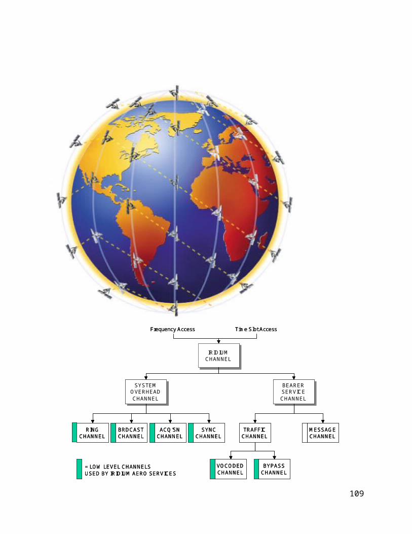
7.2 AEEC and ARINC CharacteristicsThe airlines used to develop common avionics characteristics within the Airline Electronic Engineering Committee (AEEC). The signal characteristics and the procedures are defined in detail in the characteristic ARINC 761, Part I (form, installation and wiring) and Part II (operational capability of the equipment and interchangeability). Continuing amendments to ARINC Characteristic 619/620 will be issued.
7.3 Minimum operational performance standards (MOPS)MOPS are the standards against which the airworthiness and functional performance of avionics equipment and installed systems is determined in the United States of America. They are developed in the public domain by the Radio Technical Commission Aeronautics (RTCA) and then adopted by the FAA as basic technical standards for equipment certified under their Technical Standard Order (TSO) programme. MOPS are used by manufacturers for bench, installation and flight testing. Other States have similar equipment approval procedures, many of them based on the RTCA MOPS or similar standards produced by other organizations.
114

RTCA has developed minimum operational performance standards for avionics supporting next generation satellite systems Doc-262.
In Europe, EUROCAE is developing MPS in parallel with RTCA.
7.4 Satellite system access approvaltbd
7.5 Avionics and certificationtbd
7.5.1 Avionicstbd
115

7.5.2 Airworthiness certificationtbd
7.5.3 Type acceptancetbd
7.5.4 Licensing and permitstbd
7.5.5 Service providerstbd
116

8 COMPARISON OF AMS(R)S SARPS AND EXPECTED IRIDIUM PERFORMANCECOMPLIANCEThis section contains information provided by Iridium Satellite LLC The Iridium AMS(R)S service will conform to the requirements of the AMS(R)S SARPs. This chapter provides additional supporting and guidance material regarding Iridium satellite AMS(R)S network’s conformity service performance and with AMS(R)S SARPs compliance. While this document mainly pertains to the Iridium service providersatellite subsystemnetwork, examples of typical numbers for end-to-end system is provided to show how theis Iridium subnetwork fits within the overall compliance of the end-to-end AMS(R)S system. Table 3-1 tabulates the AMS(R)S SARPs requirements and the associated Iridium specific performance parameters.
The actual verification of the Iridium AMS(R)S service system compliance with against the AMS(R)S SARPs is beyond the scope of this Technical mManual. and will be coordinated by Iridium Satellite LLC, its AeronauticalAMS(R)S sService pProviders and AES manufacturers, and the Civil Aviation Authorities (CAA) of States during the certification process for the States.
Compliance with RTCA DO-262 and DO-270 is recommended as one means of assuring that an Iridium AMS(R)S will perform its intended functions satisfactorily under all conditions normally
117

encountered in routine aeronautical operations. Any regulatory application of RTCA DO-262 and DO-270 is the sole responsibility of appropriate national authorities.
The following sections are mainly organized in a similar fashion as the AMS(R)S SARPs.
8.1 RF CharacteristicsThe Iridium AMS(R)S AES should be designed and manufactured to meet the emission and susceptibility requirements of RTCA DO-262, which is currently required for certification by FAA’s Technical Standard Order, TSO-C159, pertaining to Avionics Supporting Next Generation Satellite Systems (NGSS). [AMS(R)S SARPs, 4.3]
Frequency Bands
The Iridium subscriber links operate in the 1616-1626.5 MHz band, which is allocated to the part of the Mobile Satellite Service (MSS) in the Earth-to-space direction on a primary basis and in the space-to-Earth direction on a secondary basis band allocated by the U.S. and international Radio Regulations (ITU Radio Regulations, No. 5.347A, No. 5.351A, No. 5.364, and No. 5.365).
This band is also allocated on a primary basis to the for AMS(R)S, subject to agreement obtained under No. 9.21 operation under (ITU Radio Regulations No. 5.367). Coordination under No.
118

9.21 should ensure that other radio services operating in the same or adjacent frequency bands on a primary basis do not cause harmful interference or claim protection from an Iridium AMS(R)S use. [AMS(R)S SARPs, 4.3.1]
The Iridium Communication SystemIridium Satellite Network also uses satellite-to-satellite radio links in the 23.18-23.38 GHz band. The Iridium feeder link utilizes a 19.4-19.6 GHz downlink and a 29.1-29.3 GHz uplink for communications between the Iridium Satellite and the Iridium Gateway/TTAC. Given the critical functions of these high capacity links, they were designed to be highly reliable with superb data integrity performance. There is no concern of using these links as part of the Iridium satellite network to support AMS(R)S communication from a channel capacity and data integrity perspective.
8.1.1 Emissions The AMS(R)S SARPs require that the total emissions of the AES necessary to meet designed system performance shall be controlled to avoid harmful interference to other systems necessary to support safety and regularity of air navigation, installed on the same or other aircraft. The Iridium AMS(R)S AES will arebe designed to meet the emission requirements of RTCA DO-262. This together with a predefined AMS(R)S antenna to GNSS antenna isolation should in
119

order to ensure that AMS(R)S equipment can be operated simultaneously and independently from other communication and navigation equipment it will notand will not cause harmful interference to GNSS and other systems necessary to support safety and regularity of air navigation, installed on the same or other aircraft. [AMS(R)S SARPs, 4.3.2]
The Iridium ISU is designed to meet the emission limits set out in ITU-R Recommendation M.1343, “Essential technical requirements of mobile earth stations for global non-geostationary mobile-satellite service systems in the bands 1-3 GHz”, as well as national/regional type-approval specifications such as FCC Part 2 and Part 25 and ETSI EN301 441 specifications. FCC and ETSI measurements regulatory testing of standard Iridium ISU have showns that the Iridium ISU meets the specified emission limitsperformance.
The Iridium ISU is designed to meet FCC Part 2 and Part 25 and ETSI EN301 441 specifications. FCC and ETSI regulatory testing of standard Iridium ISU shows that the Iridium ISU meets the specified emission performance.
Iridium ISUs have been installed in numerous types of aircrafts including transport category aircraft commercial airliners by various Iridium AES manufacturers. These Iridium ISUs, though
120

not currently for AMS(R)S use, obtained type approval from FAA for use on board on commercial airlinerSome CAAs have already approved installation of Iridium ISUAES on transport category aircraft commercial airliners for non-AMS(R)Ssafety communication uses.s.
If needed for AMS(R)S, a bandpass filter with passband frequency of 1616-1626.5 MHz can be specified and placed at the output of an AMS(R)S AES equipment to provide additional emission protection.
8.1.2 SusceptibilityThe Iridium AMS(R)S AES equipment shall operate properly in an interference environment causing a cumulative relative change in its receiver noise temperature (ΔT/T) of 25 per centwill operate properly in an interference environment causing a cumulative relative change in its receiver noise temperature (ΔT/T) of 25%. [AMS(R)S SARPs, 4.3.3]25% increase in receiver noise temperature is equivalent to a 0.6 dB link margin degradation. This additional degradation due to interference is accounted for in the Iridium link budget calculation. The Iridium service uplink and downlinks are designed to provide a 15 dB link marginIridium operates with sufficient link margin to meet this requirement at all time.
121

8.2 Priority and Preemptive Access The basis for Iridium AMS(R)S Priority, Precedence, and Pre-emption (PPP) is the set of mechanisms designed for, and already implemented in, the Iridium Communication SystemIridium Satellite Network for signaling and system management purposes. The Iridium Communication SystemIridium Satellite Network utilizes two resource management functions, Acquisition Class control and Priority Class control, to assure access to communication channels for priority users. [AMS(R)S SARPs, 4.4]
The acquisition process is one of several protocols completed between an ISU and the satellite constellation for each call set up regardless if the call is mobile originated (from aircraft) or mobile terminated (to aircraft). For mobile originated call, the ISU will start the acquisition process once the call is placed. For mobile terminated call, the ISU will start the acquisition process upon the reception of a RING, indicating an incoming call from the GES.
Each satellite beam broadcasts which Acquisition Classes are allowed to acquire satellite resource on that beam. Only ISUs with the proper Acquisition Class (AC) are allowed to start the acquisition process. Acquisition Class ranges from 0-15. Default non-safety Iridium terminals use an Acquisition Class in the range of 0-9. AMS(R)S safety traffic will be assigned Acquisition Class 14.
122
Acquisition Class is mainly use for SV load shedding. In a satellite beam with heavy traffic load, certain Acquisition Classes (e.g., AC0-9) will be shut down to prohibit further traffic load on the satellite. To ensure AMS(R)S safety traffic will get through, Iridium will not shut down AC14 for SV load shedding.
The Acquisition Class affects how calls initially gain access to the satellite constellation while Priority Class provides continued access for safety-related calls.
The Iridium Communication SystemIridium Satellite Network allows for four levels of priority. Each satellite has priority queuing for both channel assignment of new calls and handoff order of in-progress calls. High priority calls, taking precedence, are queued before low priority calls.
The four Iridium priority levels are mapped to the four-level AMS(R)S priority structure as specified by Table 2-7 of RTCA DO-262.
Iridium Priority 3 (AMS(R)S #4, Distress, Urgency, highest priority); Iridium Priority 2 (AMS(R)S #3, Direction finding, Flight Safety); Iridium Priority 1 (AMS(R)S #2, Other Safety and Regularity of Flight); Iridium Priority 0 (AMS(R)S #1, AMSS Non-Safety, lowest priority).
123

In case of extreme system resource shortage, on-going low priority calls will be pre-empted by the system to allow access for higher priority call.
While the Iridium Acquisition Class Control and Priority Class Control provide internal system controls for internal PPP management, the Iridium AMS(R)S AES manufacturers and AMS(R)S sService pProviders will need to provide the input/output queuing for call/message priority function at the Iridium network interfaces. These capabilities are intrinsic to the protocol machines that interface Iridium AMS(R)S with its external users, and reside in the AMS(R)S AES and GES.
Currently both the Acquisition Class and Priority Class are encoded on a SIM card; hence the Acquisition Class and Priority Class are associated with a SIM card and an ISU that uses that SIM card. For AMS(R)S, the acquisition class and priority class will need to be associated with each AMS(R)S call (type) and will be controlled by the protocol software that sets up the call.
Iridium AMS(R)S AES and GES will support Priority, Precedence and Pre-emption to ensure that messages transmitted in accordance with Annex 10, Volume II, 5.1.8, including their order of priority, are not delayed by the transmission and/or reception of other types of messages. [AMS(R)S SARPs, 4.4.1]
124

All AMS(R)S data packets and all AMS(R)S voice calls will be identified as to their associated priority. [AMS(R)S SARPs, 4.4.2]
Within the same message category, the Iridium AMS(R)S service will provide voice communications priority over data communications. [AMS(R)S SARPs, 4.4.3]
8.3 Signal Acquisition and TrackingThe AMS(R)S SARPs require that Iridium AES, GES and satellites properly acquire and track service link signals when the aircraft is moving at a ground speed of up to 1500 km/h along any heading [AMS(R)S SARPs, 4.5.1] and when the component of the aircraft acceleration vector in the plane of the satellite orbit is up to 0.6 g. [AMS(R)S SARPs, 4.5.2]
The Iridium Communication SystemIridium Satellite Network consists of fast moving LEO SVs and is hence designed to handle large Doppler frequency shift and Doppler rate of change. The signal acquisition and tracking functions are handled internally within the Iridium Communication SystemIridium Satellite Network by the ISU and the SVs and are transparent to the Iridium users.
125

Link synchronization is achieved by pre-correcting the ISU transmit timing and frequency so that uplink bursts arrive at the SV in the correct time slot and on the correct frequency access for the assigned channel. This pre-correction is accomplished by adjusting the ISU timing and frequency in accordance with error feedback which is sent in the downlink maintenance messages by the SV. The ISU will compensate for a maximum uplink carrier frequency Doppler shift of up to +/-37.5 KHz to achieve the specified uplink frequency of arrival requirements. The ISU receiver will accommodate a carrier frequency Doppler shift of up to +/-37.5 KHz.
Since the Iridium Communication SystemIridium Satellite Network became operational, the Iridium ISUs have been demonstrated to maintain link connectivity in numerous test flights onboard jets and research rockets. A recent test involved the NASA Sounding Rocket was conducted in April 2004. An Iridium flight modem, consisted of an Iridium ISU and other electronics, integrated and packaged by NASA, sent data successfully and continuously from lift-off through 2 rocket stage burns, reaching a peak velocity of to 1.5 km/sec (5400 km/h), and only cut out when the rocket tumbled at apogee (120 km). The flight modem reacquired after the first parachute deployed and data was sent until the rocket hit the ground with a reported force of 50 g’s. The Iridium link was maintained on impact and the flight modem continued to transmit for
126

another 25 minutes. This and other demonstrations show that Iridium communication links are robust for high speed flights with large Doppler offset and Doppler rate of change.
The Iridium AES, GES and satellites will properly acquire and track service link signals when the aircraft is moving at a ground speed of up to 1500 km/h along any heading. [AMS(R)S SARPs, 4.5.1]
The Iridium AES, GES and satellites will properly acquire and track service link signals when the component of the aircraft acceleration vector in the plane of the satellite orbit is up to 0.6 g. [AMS(R)S SARPs, 4.5.2]
The Iridium AES, GES and satellites should be able to properly acquire and track service link signals when the aircraft is moving at a ground speed of up to 2800 km/h along any heading and the component of the aircraft acceleration vector in the plane of the satellite orbit is up to 1.2 g. These will be further verified during Iridium AMS(R)S certification process. [AMS(R)S SARPs, 4.5.1.1, 4.5.2.1]
127

8.4 Performance Requirements
8.4.1 Designated Operational CoverageIridium Communication SystemIridium Satellite Network provides is the only truly global and truly mobile communication system in the world with operational Ppole to Ppole coverage of the entire the entire eEarth from Pole to Pole. Figure 3-1, which is based on Iridium voice call traffic statistics, confirms this truly global coverage. .
Iridium plans to provide AMS(R)S as an alternative and/or redundant communications capability in oceanic/remote/polar (ORP) region with the ability to provide alternative and/or redundant communications capability for continental flights as appropriate. [AMS(R)S SARPs, 4.6.1.1]
128

Figure 3-1 Global Reach of Iridium
129

8.4.2 Failure NotificationThe AMS(R)S SARPs require that in the event of a service failure, the Iridium AMS(R)S system shall provide timely predictions of the time, location and duration of any resultant outages until full service is restored. [AMS(R)S SARPs, 4.6.2.1] The system shall annunciate a loss of communications capability within 30 seconds of the time when it detects such a loss. [AMS(R)S SARPs, 4.6.2.2]
As an operational network serving hundreds of thousands of subscribers all over the globe, the Iridium Satellite Network is being permanently monitored 24/7 by its Network Operation and Maintenance Contractor, the Boeing Corporation. There are methods and processes in place for network outage detection, prediction, reporting, warning, and remediation. The current processes require further amendment to ensure that an Iridium AMS(R)S system will annunciate a loss of communications capability within 30 seconds of the time when it detects such a loss.
Iridium and its AMS(R)S sService pProviders will ensure the AMS(R)S system, in the event of a service failure, will provide timely predictions of the time, location and duration of any resultant outages until full service is restored. [AMS(R)S SARPs, 4.6.2.1]
130

Iridium and its AMS(R)S sService Pproviders will amend the current process to ensure the AMS(R)S system will annunciate a loss of communications capability within 30 seconds of the time when it detects such a loss. [AMS(R)S SARPs, 4.6.2.2]
AES Requirements
The Iridium AMS(R)S AES should meet the relevant performance requirements contained in voice and data performance requirements of the AMS(R)S SARPs for aircraft in straight and level flight throughout the designated operational coverage of the Iridium satellite system. These will be further verified during Iridium AMS(R)S certification process. [AMS(R)S SARPs, 4.6.3.1]
The Iridium AMS(R)S AES should meet the relevant performance requirements contained in voice and data performance requirements of the AMS(R)S SARPs for aircraft attitudes of +20/-5 degrees of pitch and +/- 25 degrees of roll throughout the designated operational coverage of the Iridium satellite system. These will be further verified during Iridium AMS(R)S certification process. [AMS(R)S SARPs, 4.6.3.1.1]
131

8.4.3 Packet Data Service PerformanceThe Iridium Communication SystemIridium Satellite Network will provides AMS(R)S packet data service in accordance with the requirements stated in the AMS(R)S SARPs. [AMS(R)S SARPs 4.6.4.1]
The AMS(R)S SARPs require that an AMS(R)S system providing a packet-data service shall be capable of operating as a constituent mobile sub-network of the ATN. The role of the ATN is to define an environment within which reliable end-to-end data transfer may take place, spanning the airborne, air/ground and ground-based data subnetworks while providing interoperability among those networks. The Iridium Satellite Network supports the transparent transfer of data between adjacent internetwork entities. This includes the transparent transfer of global ATN addresses and quality of service information, as well as user data. The AMS(R)S subnetwork interface to an ATN router occurs within the ATN network layer, thus control information for the data link and physical layers is not passed from subnetwork to subnetwork. Hence, the subnetwork may utilize non-ATN conforming protocols within these layers while maintaining ATN protocol architecture conformance within the network layer. As stated earlier, the Iridium Satellite Network should be treated as a transmission medium. The AES on the aircraft and the Aeronautical AMS(R)S Ground Subsystem (AGS) on the terrestrial side together with the
132

Iridium satellite network constitute a mobile sub-network of the ATN or other data (e.g., Data-2) network. Whilst it is not strictly required to adopt a common standard subnetwork interface protocol for all air/ground subnetworks, it greatly simplifies the implementation and validation of the internetwork process since only a single communication software package is required to service the interface with the different air/ground subnetworks. The ISO 8208 packet level protocol has been adopted as the standard for this interface. A subnetwork interface protocol for an Iridium AMS(R)S has not yet been specified by ICAO. Thus, compliance of the Iridium Satellite Network with AMS(R)S SARPs requires the specification and development of an appropriate subnetwork interface protocolwill work with its AES manufacturers and AeronauticalAMS(R)S sService pProviders to ensure the Iridium AMS(R)S packet-data service will be capable of operating as a constituent mobile sub-network of the ATN. The AES and the AGS will provide ATN-compatible network interface. [AMS(R)S SARPs 4.6.4.1.1]
Iridium offers a multitude of data services, of which tThe Iridium RUDICS and SBD data services are advantageous well suited for different AMS(R)S application. RUDICS offers the shortest call establishment time among all standard Iridium circuit-switch data services. SBD, though also based on circuit switch channel, offers a data transport service which looks more like
133

a packet data call. The following performance parameters are based on statistics accumulated over many years of Iridium Communication SystemIridium Satellite Network operation.
Traditional The Iridium data service, liked RUDICS, is based on circuit-switch mode. Data circuit is established and the channel stays up until the connection is torn down. The connection establishment time for a RUDICS call ranges from 10-14 sec. Once the circuit is established, the channel provides a reliable transport service of 2.4 kbps as a minimum with a more typical throughput around 2.6 kbps.
Since the Iridium SBD service utilizes only the Access phase of the normal Iridium call establishment, it does not traverse the full path of the Iridium Gateway to the GSM switch and hence has a shorter call establishment delay. In fact, there is really no standard call set up for SBD. SBD call can send data immediately as soon as the Acquisition process is completed, which on average is about 1.5 sec. Therefore, the average call establishment time is about 1.5 sec for MO SBD and 3.6 sec for MT SBD, assuming an average RING alert duration of 2.1 sec in a typical operating environment. Since SBD utilizes the signalling channel payload (with FEC protection) rather than the normal traffic channel payload, its average throughput is less than that of standard Iridium data services such as RUDICS and is around 1.2 kbps.
134

Since the Iridium Satellite Network provides AMS(R)S packet data service it shall meet the delay and integrity requirements as stated below. [AMS(R)S SARPs 4.6.4.1]
8.4.3.1 Delay ParametersBased on accumulated Iridium satellite network performance statistics accumulated over the years, the connection establishment delay of a RUDICS based packet data call can be expected to be will be much less than 30 sec. and that the connection establishment delay of a SBD based packet data call will be much less than 8 sec. [AMS(R)S SARPs, 4.6.4.1.2.1]
Assuming With a subnetwork service data unit (SNSDU) length of 128 octets, the Iridium satellite subnetwork will supports the following transit delay values:
For RUDICS based packet data service, the expected transit delay (average transfer delay) of a 128-byte payload will be around 128x8/2400 = 0.43 sec. For SBD based packet data service, the expected transit delay of a 128-byte message will be around 128x8/1200 = 0.86 sec. Hence, the transit delay of the highest priority packet should be less than 5 sec. regardless if it is from AES or GES. [AMS(R)S SARPs, 4.6.4.1.2.3, 4.6.4.1.2.4]
135

Based on the earlier discussion and the average transfer delay value, therefore the 95th percentile transfer delay should be less than 15 seconds for the highest priority data service whether it is from-aircraft or to-aircraft. [AMS(R)S SARPs, 4.6.4.1.2.5, 4.6.4.1.2.6]
Based on operational experience and performance statistics, most calls are released within 2 sec. Hence, connection release delay for all calls should be less than 5 sec. [AMS(R)S SARPs, 4.6.4.1.2.7]
8.4.3.2 IntegrityThe AMS(R)S SARPs specifies packet data service integrity by residual error rate. and iIt further defines residual error rate as the combination of the probabilitiesy of undetected error, the probability of undetected loss of an subnetwork service data unit (SNSDU) and the probability of an undetected duplicate SNSDU.
Regarding probabilities of undetected loss and undetected duplicate, both the Iridium circuit switch data transport and the Iridium SBD protocol employs message sequence number and automatic repeat request (ARQ) retransmission at the Iridium PDU level. For SBD, message sequence number (MSN) is also applied at the SNSDU level. These mechanisms will ensure that
136

the required probabilities of Regardless of where the MSN is applied, it is impossible to have for undetected loss and undetected duplicate of an SNSDU can be met.
Probability of undetected error is simply the packet error rate.
For RUDICS based packet data service, part of the analysis provided in a previous working group paper, WGA/14 WP-599 Attachment 5, still applies. The reliable mode circuit-switch data employs a 24-bit frame check sequence and the user payload field in an Iridium PDU is 248 bits. To transport a 128-byte data packet, it will take 5 Iridium PDUs. WP-599 Attachment 5 shows using simple analysis that the probability of a 128-byte data packet in error is about 3x10⁻⁷. WP-599 continues to show that the packet error rate can be further reduced if additional protocol layer with additional error detection capability is employed. For the purpose of this technical manual, we will simply assume theIt is assumed that a packet error rate of 3x10⁻⁷ can be achieved with no and do not further assume additionalfurther enhancedment provided by other protocol layer.
The SBD service uses the Iridium signalling channel for data transport and is a guaranteed delivery service with multiple layers of error protection. It employs forward error control in the form of BCH coding in additional to selective ARQ. By design, the SBD data transport has will havea better packet error rate performance than the circuit switch data transport.
137

It is expected that tThe Iridium AMS(R)S packet data can provide will have a residual error rate no greater than 10-6 per SNSDU, whether it is from-aircraft or to-aircraft. [AMS(R)S SARPs, 4.6.4.1.3.1, 4.6.4.1.3.2]
For the Iridium AMS(R)S, The a probability of a subnetwork connection (SNC) provider-invoked SNC release will beof less than 10-4 over any one-hour interval. [AMS(R)S SARPs, 4.6.4.1.3.3] and a
The probability of an SNC provider-invoked reset will beof less than 10-1 over any one-hour interval. [AMS(R)S SARPs, 4.6.4.1.3.4] can be expected.
The probability of provider-invoked SNC release and SNC reset will be verified for the Iridium AMS(R)S certification process.
8.4.4 Voice Service PerformanceIridium AMS(R)S will support both voice and data services and tThe The AMS(R)S SARPs require that an Iridium AMS(R)S voice service shallwill meet the requirement of the following subsections.AMS(R)S SARPs. [AMS(R)S SARPs, 4.6.5.1]
138

8.4.4.1 Call Processing DelayBased on Iridium satellite networkpast operational experience and performance statistics, most mobile-originated and mobile-terminated voice calls take 12 sec and 14 sec to set up, respectively.
For Iridium AMS(R)S, the 95th percentile of the time delay for a GES to present a call origination event to the terrestrial network interworking interface after a call origination event has arrived at the AES interface will should not be greater than 20 seconds. In order to verify the 95th percentile number, additional data will need to be gathered to build the cumulative probability density function. This will be done as part of the Iridium AMS(R)S verification efforts. [AMS(R)S SARPs, 4.6.5.1.1.1]
For Iridium AMS(R)S, the 95th percentile of the time delay for an AES to present a call origination event at its aircraft interface after a call origination event has arrived at the terrestrial network interworking interface will should not be greater than 20 seconds. In order to verify the 95th percentile number, additional data will need to be gathered to build the cumulative probability density function. This will be done as part of the Iridium AMS(R)S verification efforts. [AMS(R)S SARPs, 4.6.5.1.1.2]
139

8.4.4.2 Voice QualityThe Iridium ISU incorporates a 2.4 kbps Advanced Multi-Band Excitation (AMBE) vocoder developed by Digital Voice System Inc. (DVSI). This proprietary vocoder is tailored to the Iridium communication channel and provides good quality audio performance with a nominal Mean Opinion Score (MOS) of 3.5 under typical non-aeronautical operating and channel condition.
Even though voice quality of Iridium terminal operating in various aeronautical environments had not been quantified, Iridium terminals have been installed and successfully operated used on various types of aircrafts including helicopters with good success. Iridium AMS(R)S voice quality will be measured and documented as part of the Iridium AMS(R)S certification efforts. [AMS(R)S SARPs, 4.6.5.1.2.1]
WGA/14 WP-599 Attachment 4 analysed theAn Iridium voice call delay. That analysis estimated a total one-way voice transfer delay over the Iridium satellite network of about 374 msec based on the assumption therein; the material presented there still applies. That estimated delay value compares well with measurements undertaken by Iridium LLCsome of the test data seen. Additional data regarding Iridium voice call delay will be gathered and documented as part of the Iridium AMS(R)S verification efforts.
140

For tThe Iridium AMS(R)S voice service will have a total voice call transfer delay within the AMS(R)S subnetwork of no greater than 0.485 second can be expected. [AMS(R)S SARPs, 4.6.5.1.2.2]
8.4.4.3 Voice CapacityIridium AMS(R)S will have sufficient available voice traffic channel resources such that an AES- or GES-originated AMS(R)S voice call presented to the system shall experience a probability of blockage of no more than 10-2. [AMS(R)S SARPs, 4.6.5.1.3.1]
An Iridium satellite beam has an average diameter of 400 km. In the The current Iridium software system configuration, system currentlyIridium can support up to 252 voice circuits per beam. We believe this capacity will support the stated probability of blockage for the intended operational coverage of oceanic/remote/polar region. [confirm statement, use PIAC from COCR for 2020 and 2030 scenario]
8.4.5 SecurityThe Iridium Communication SystemIridium Satellite Network being an operational satellite service employs various security measures against external attack and tampering.
141

Iridium Channel Security
The complexity of its air interfaces makes it very difficulthard to be intercepted and to be tampered.
To successfully monitor an L-band channel, an eavesdropper must be located within the transmit range of the ISU being monitored, approximately 10 to 30 km from the transmitting ISU [This numbers are true for ground based ISU and eavesdropper only ?! These numbers should be different for airborne ISU ???]. ISU downlink L-Band transmissions could be received over a much wider area. A single SV beam covers an area of about 400 km in diameter.
The complexity of the Iridium air interface would make the challenge of developing an Iridium L-Band monitoring device very difficult. Among the complications are
Large, continually changing Doppler shifts Frequent inter-beam and inter-SV handoffs Time-division multiplexed burst mode channels Complicated modulation, interleaving and coding
142

A sophisticated monitoring device would be needed in the general proximity of an Iridium gateway to receive the feederlink channel.
The complexity of the feederlink interface poses a formidable technical challenge for prospective eavesdroppers. Among the technical complications are
Large, continually changing Doppler shifts High capacity, ~3 Mbps channels High-gain tracking antenna required Must reacquire new SV every 10 minutes
This security aspect of the Iridium Communication SystemIridium Satellite Network provides protection against tampering of messages in transit. [AMS(R)S SARPs, 4.6.6.1]
Space Segment Security
The Iridium Communication SystemIridium Satellite Network uses command authentication and encryption to safeguard critical commands to the satellite constellation. These features provide protection against unauthorized entry, spoofing, and “phantom controllers”.
143
This security aspect of the Iridium Communication SystemIridium Satellite Network provides protection against unauthorized entry. [AMS(R)S SARPs, 4.6.6.3]
Physical Security
The Iridium Gateway, its Master Control Facility, and its Telemetry, Tracking And Control stations are all secured facilities.
This security aspect of the Iridium Communication SystemIridium Satellite Network provides protection against unauthorized entry. [AMS(R)S SARPs, 4.6.6.3]
Authentication Security
The Iridium authentication process is adapted without change directly from the GSM specifications. The GSM algorithm A3 is used to encrypt authentication information transmitted over the air interface.
Authentication encryption Designed to prevent ISU cloning fraud
144
GSM encryption algorithm A3 is executed on SIM card to generate Signed Result (SRES) response based on the following inputs Secret Ki parameter stored in SIM card RAND parameter supplied by network
This security aspect of the Iridium Communication SystemIridium Satellite Network provides the same level of protection against certain type of denial of service such as intentional flooding of traffic as currently implemented in the GSM. [AMS(R)S SARPs, 4.6.6.2]
8.5 System InterfacesThe AMS(R)S SARPs require that an AMS(R)S system providing a packet-data service shall be capable of operating as a constituent mobile sub-network of the ATN. The Iridium Satellite Network supports the transparent transfer of data between adjacent internetwork entities. This includes the transparent transfer of global ATN addresses (e.g. 24 bit aircraft addresses) and quality of service information, as well as user data. A subnetwork interface protocol for an Iridium AMS(R)S has not yet been specified by ICAO. Thus, compliance of the Iridium Satellite Network with AMS(R)S SARPs requires the specification and development of an appropriate subnetwork interface protocol.
145

Iridium will work with its AeronauticalAMS(R)S sService pProviders and AMS(R)S AES manufacturers to ensure that the Iridium AMS(R)S system will allow subnetwork users to address AMS(R)S communications to specific aircraft by means of the ICAO 24-bit aircraft address. [AMS(R)S SARPs, 4.7.1] and
Iridium will work with its AeronauticalAMS(R)S sService pProviders to ensure that the Iridium AMS(R)S system will provide an interface to the ATN as well as a connectivity notification (CN) function. [AMS(R)S SARPs, 4.7.2.1, 4.7.2.2]
146

Table 3-1 Iridium AMS(R)S System Parameters per ICAO AMS(R)S SARPsAMS(R)S
SARPs Reference
AMS(R)S SARP Contents
Iridium Subnetwork
Specific Value3
Allocation to Network External to
Iridium
Additional Additional Comments on PerformanceVerification
4.2.1 AMS(R)S shall conform to ICAO Chapter 4
YesYes Yes -
4.2.1.1 Recommendation to ensure CNS protection by AMSS system
YesYes Yes -
4.2.1.2 Support packet data, voice, or both
Yes; both
Yes By design.
4.2.2 Mandatory equipage N/A for service
provider
- -
4.2.3 2 year's notice N/A for service
provider
- -
3 Iridium supplied values.
147

AMS(R)S SARPs
Reference
AMS(R)S SARP Contents
Iridium Subnetwork
Specific Value
Allocation to Network External to
Iridium
Additional Additional Comments on PerformanceVerification
4.2.4 Recommendation consider worldwide implementation
Yes Yes -
4.3.1.1 Only in frequency bands allocated to AMS(R)S and protected by ITU RR
Yes;1616-1626.5
MHz
- -
4.3.2.1 Limit emissions to control harmful interference on same aircraft
Yes - (M) AES emission to be measured by AES equipment manufacturer per RTCA DO262.
4.3.2.2 Shall not cause harmful interference to AMS(R)S on other aircraft
Yes - (M) AES emission to be measured by AES equipment manufacturer per RTCA DO262.
4.3.3.1 Shall operate properly in cumulative T/T of 25%
Yes - (M) AES emission to be measured by AES equipment manufacturer per RTCA DO262.
4.4.1 Priority and pre-emptive access
Yes Yes By design.(I(M) To be verified by AES manufacturer per RTCA DO262.
148

AMS(R)S SARPs
Reference
AMS(R)S SARP Contents
Iridium Subnetwork
Specific Value
Allocation to Network External to
Iridium
Additional Additional Comments on PerformanceVerification
4.4.2 All AMS(R)S packets and voice calls shall be identified by priority
Yes Yes (I) To be verified by AMS(R)S Service Providers (SP).
4.4.3 Within the same msg category, voice has priority over data
Yes Yes (I) To be verified by AMS(R)S SP.
4.5.1 Properly track signal for A/C at 800 kt. along any heading
Yes - Verified by operational experience.
4.5.1.1 Recommendation for 1500 kts.
TBD - (M) To be verified by AES manufacturer.
4.5.2 Properly track with 0.6 g acceleration in plane of orbit
Yes - Verified by operational experience.
4.5.2.1 Recommendation 1.2 g TBD - (M) To be verified by AES manufacturer.
149

AMS(R)S SARPs
Reference
AMS(R)S SARP Contents
Iridium Subnetwork
Specific Value
Allocation to Network External to
Iridium
Additional Additional Comments on PerformanceVerification
4.6.1.1 Provide AMS(R)S throughout Designated Operational Coverage
Yes;Oceanic / remote /
Polar (ORP) region
- Verified by operational experience. Verified by current traffic location on the network.
4.6.2.1 Provide timely predictions of service failure-induced outages
Yes Yes (I) : By process to be set up with AMS(R)S SPService Providers.
4.6.2.2 Within 30 s Yes Yes (I) By process to be set up with AMS(R)S SP.(I): By process to be set up with Service Providers.
4.6.3.1 Meet performance in straight and level flight
Yes - (I(M) To be verified by AES manufacturer.
4.6.3.1.1 Recommendation for +20/-5 pitch ant +/-25 roll
TBD - (I(M) To be verified by AES manufacturer.
4.6.4.1 Requirements on AMS(R)S packet data
Yes - See subsections.
150

AMS(R)S SARPs
Reference
AMS(R)S SARP Contents
Iridium Subnetwork
Specific Value
Allocation to Network External to
Iridium
Additional Additional Comments on PerformanceVerification
4.6.4.1.1 Capable of mobile subnetwork in ATN
Yes;ISO-8028
Yes (IM) To be verified by AMS(R)S Service Provider SP when end-to-end system is implemented.
4.6.4.1.2.1 Connection establishment delay < 70 seconds
Yes; < 30s TBD?? Iridium subnetwork performance Vverified by current performance data.(M) End-to-end performance Tto be further verified by AMS(R)S Service ProviderSP when end-to-end system is implemented.
4.6.4.1.2.1.1 Recommendation Connection establishment delay < 50 seconds
Yes; < 30s TBD?? Iridium subnetwork performance verified by current performance data.(M) End-to-end performance to be verified by AMS(R)S SP when end-to-end system is implemented.Verified by current performance data.(M) To be further verified by AMS(R)S Service Provider when end-to-end system is implemented.
151

AMS(R)S SARPs
Reference
AMS(R)S SARP Contents
Iridium Subnetwork
Specific Value
Allocation to Network External to
Iridium
Additional Additional Comments on PerformanceVerification
4.6.4.1.2.2 Transit delay based on SNSDU of 128 octets and defined as average values
Yes Yes -
4.6.4.1.2.3 From A/C High priority < 23 seconds
Yes; < 5s TBD?? Iridium subnetwork performance verified by current performance data.(M) End-to-end performance to be verified by AMS(R)S SP when end-to-end system is implemented.Verified by current performance data.(M) To be further verified by AMS(R)S Service Provider when end-to-end system is implemented.
152

AMS(R)S SARPs
Reference
AMS(R)S SARP Contents
Iridium Subnetwork
Specific Value
Allocation to Network External to
Iridium
Additional Additional Comments on PerformanceVerification
4.6.4.1.2.3.1 Recommendation from A/C Low prioirty < 28 seconds
Yes; < 10s TBD?? Iridium subnetwork performance verified by current performance data.(M) End-to-end performance to be verified by AMS(R)S SP when end-to-end system is implemented.(M) To be verified by AMS(R)S Service Provider when end-to-end system is implemented.
4.6.4.1.2.4 To A/C high priority < 12 seconds
Yes; < 5s TBD?? Iridium subnetwork performance verified by current performance data.(M) End-to-end performance to be verified by AMS(R)S SP when end-to-end system is implemented.Verified by current performance data.(M) To be further verified by AMS(R)S Service Provider when end-to-end system is implemented.
153

AMS(R)S SARPs
Reference
AMS(R)S SARP Contents
Iridium Subnetwork
Specific Value
Allocation to Network External to
Iridium
Additional Additional Comments on PerformanceVerification
4.6.4.1.2.4.1 Recommendation To A/C low priority < 28 seconds
Yes; < 10s TBD?? Iridium subnetwork performance verified by current performance data.(M) End-to-end performance to be verified by AMS(R)S SP when end-to-end system is implemented.(M) To be verified by AMS(R)S Service Provider when end-to-end system is implemented.
4.6.4.1.2.5 From A/C Data transfer delay 95%ile high priority < 40 seconds
Yes; < 15s TBD?? Iridium subnetwork performance verified by current performance data.Verified by current performance data.(M) End-to-end 95%ile value requires CDF statistics. To be further verified by AMS(R)S SP when end-to-end system is implemented.
154

AMS(R)S SARPs
Reference
AMS(R)S SARP Contents
Iridium Subnetwork
Specific Value
Allocation to Network External to
Iridium
Additional Additional Comments on PerformanceVerification
4.6.4.1.2.5.1 Recommendation From A/C Data transfer delay 95%ile low priority < 60 seconds
Yes; TBD< 30s
TBD?? (M) End-to-end 95%ile value requires CDF statistics. To be further verified by AMS(R)S SP when end-to-end system is implemented.Verified by current performance data.(M) 95%ile value requires CDF statistics. To be further verified by AMS(R)S SP when end-to-end system is implemented.
4.6.4.1.2.6 To A/C Data transfer delay 95%ile high priority < 15 seconds
Yes; < 87.515s
TBD?? Iridium subnetwork performance verified by current performance data.(M) End-to-end 95%ile value requires CDF statistics. To be further verified by AMS(R)S SP when end-to-end system is implemented.(M) 95%ile value requires CDF statistics. To be further verified by AMS(R)S SP when end-to-end system is implemented.
155

AMS(R)S SARPs
Reference
AMS(R)S SARP Contents
Iridium Subnetwork
Specific Value
Allocation to Network External to
Iridium
Additional Additional Comments on PerformanceVerification
4.6.4.1.2.6.1 Recommendation To A/C Data transfer delay 95%ile low priority < 30 seconds
Yes; TBD< 30s
TBD?? (M) End-to-end 95%ile value requires CDF statistics. To be further verified by AMS(R)S SP when end-to-end system is implemented.Verified by current performance data.(M) 95%ile value requires CDF statistics. To be further verified by AMS(R)S SP when end-to-end system is implemented.
4.6.4.1.2.7 Connection release time 95%ile < 30 seconds
Yes; < 5s TBD?? Iridium subnetwork performance verified by current performance data.(M) End-to-end 95%ile value requires CDF statistics. To be further verified by AMS(R)S SP when end-to-end system is implemented.Verified by current performance data.(M) To be further verified by AMS(R)S SP when end-to-end system is implemented.
156

AMS(R)S SARPs
Reference
AMS(R)S SARP Contents
Iridium Subnetwork
Specific Value
Allocation to Network External to
Iridium
Additional Additional Comments on PerformanceVerification
4.6.4.1.2.7.1 Recommendation connection release time 95%ile < 25 seconds
Yes; < 5s TBD?? Iridium subnetwork performance verified by current performance data.(M) End-to-end 95%ile value requires CDF statistics. To be further verified by AMS(R)S SP when end-to-end system is implemented.Verified by current performance data.(M) To be further verified by AMS(R)S SP when end-to-end system is implemented.
4.6.4.1.3.1 Residual error rate from A/C < 10-4/SNSDU
Yes; < 10-6 - Verified by current performance data.(M) To be further verified by AMS(R)S SP when end-to-end system is implemented.
4.6.4.1.3.1.1 Recommend RER from A/C < 10-6/SNSDU
Yes; < 10-6 - Verified by current performance data.(M) To be further verified by AMS(R)S SP when end-to-end system is implemented.
157
AMS(R)S SARPs
Reference
AMS(R)S SARP Contents
Iridium Subnetwork
Specific Value
Allocation to Network External to
Iridium
Additional Additional Comments on PerformanceVerification
4.6.4.1.3.2 RER to A/C < 10-6 /SNSDU Yes; < 10-6 - Verified by current performance data.(M) To be further verified by AMS(R)S SP when end-to-end system is implemented.
4.6.4.1.3.3 Pr{SNC provider invoked release}< 10-4/hr
Yes; < 10-
4/hrTBD?? (M) To be verified by AMS(R)S SP when
end-to-end system is implemented.4.6.4.1.3.4 Pr{SNC provider invoked
reset}< 10-1/hrYes; < 10-
1/hrTBD?? (M) To be verified by AMS(R)S SP when
end-to-end system is implemented.4.6.5.1 Requirements for AMS(R)S
voice serviceYes Yes -
158

AMS(R)S SARPs
Reference
AMS(R)S SARP Contents
Iridium Subnetwork
Specific Value
Allocation to Network External to
Iridium
Additional Additional Comments on PerformanceVerification
4.6.5.1.1.1 AES call origination delay 95%ile < 20 seconds
Yes; < 20s TBD?? Iridium subnetwork performance verified by current performance data.(M) CDF statistics are needed for 95%ile value verification; to be further verified by AMS(R)S SP.Verified by current performance data.(M) CDF statistics are needed for 95%ile value verification; to be further verified by AMS(R)S SP.
4.6.5.1.1.2 GES call origination delay 95%ile < 20 seconds
Yes; < 20s TBD?? Iridium subnetwork performance verified by current performance data.Verified by current performance data.(M) CDF statistics are needed for 95%ile value verification; to be further verified by AMS(R)S SP.
159

AMS(R)S SARPs
Reference
AMS(R)S SARP Contents
Iridium Subnetwork
Specific Value
Allocation to Network External to
Iridium
Additional Additional Comments on PerformanceVerification
4.6.5.1.2.1 Voice intelligibility suitable for intended operational and ambient noise environment
Yes Yes (M) To be verified by AES manufacturer.
4.6.5.1.2.2 Total allowable transfer delay within AMS(R)S subnetwork < 0.485 second
Yes; < 0.485s
- Verified by current performance data.(M) To be further verified by AMS(R)S SP when end-to-end system is implemented.
4.6.5.1.2.3 Recommendation to consider effects of tandem vocoders
TBD - -
4.6.5.1.3.1 Sufficient voice traffic channel resources for Pr{blockage < 0.01} for AES or GES originated calls
Yes; < 0.01 - (A) Awaiting clarification of future traffic model to complete analysis.(M) To be further verified by AMS(R)S SP when end-to-end system is implemented.
4.6.6.1 Protect messages from tampering
Yes Yes -
160
AMS(R)S SARPs
Reference
AMS(R)S SARP Contents
Iridium Subnetwork
Specific Value
Allocation to Network External to
Iridium
Additional Additional Comments on PerformanceVerification
4.6.6.2 Protect against denial of service, degradation, or reduction of capacity due to external attacks
Yes Yes -
4.6.6.3 Protect against unauthorized entry
Yes Yes -
4.7.1 Address AMS(R)S by means of 24 bit ICAO address
Yes Yes By design.
4.7.2.1 If the system provides packet data service, it shall provide an interface to the ATN
Yes Yes By design.
4.7.2.2 If the system provides packet data service, it shall provide an CN function
Yes Yes By design.
161

9 IMPLEMENTATION GUIDANCE
9.1 THEORY OF OPERATION
9.2 SERVICES SUPPORTED
9.3 OPERATION
9.4 AVIONICS
9.5 FUTURE SERVICES
162

APPENDIX A: AIRCRAFT EARTH STATION RF CHARACTERISTICSFAA’s Technical Standard Order, TSO-C159, states that “Avionics Supporting Next Generation Satellite Systems (NGSS)” identified and manufactured on or after the effective date (20 September 2004) of the TSO must meet the minimum operational performance standards (MOPS) specified in RTCA DO-262.
RTCA DO-262 is a normative specification dealing mainly with RF characteristics and performance of AES supporting NGSS. Each NGSS is to provide system specific performance specification so that RF performance of AES built for that particular satellite system could be tested and verified.
Table A-1 tabulates some of the system specific performance parameters for the Iridium communication satellite system per RTCA DO-262. Iridium will work with its AES manufacturers in understanding the MOPS and the Iridium specific system parameters.
163

Table A-1 Iridium AMS(R)S System Parameters per RTCA DO-262Symbol Characteristics System
Specific Value
Paragraph Reference
ARSV System-specific axial ratio for space vehicle. This parameter is used only to compute the gain necessary to overcome losses due to mismatch of the axial ratios.
3.5 dB DO-262 2.2.3.1.1.2
fRMX Maximum operating frequency for space vehicle transmissions (AES reception)
1626.5 MHz DO-262 2.2.3.1.1.4
fRMN Minimum operating frequency for space vehicle transmissions (AES reception)
1616.0 MHz DO-262 2.2.3.1.1.4
fTMX Maximum operating frequency for AES transmissions
1626.5 MHz DO-262 2.2.3.1.1.4
fTMN Minimum operating frequency for AES transmissions
1616.0 MHz DO-262 2.2.3.1.1.4
164

Symbol Characteristics System Specific Value
Paragraph Reference
fM Channel modulation rate 50 kbps DO-262P Nominal polarization of AES antenna RHCP DO-262 2.2.3.1.1.1.2
PNC Maximum output power allowed during intervals when no transceiver channel is transmitting
-77 dBW / 100 kHz
DO-262 2.2.3.1.2.1.7
SD Minimum data channel carrier level for sensitivity test
-114 dBm DO-262 2.2.3.1.2.2.1.1
SHSNT Maximum level of harmonic, spurious and noise allowed within the designated transmit band
-35 dBW / 100 kHz
DO-262 2.2.3.1.2.1.5
SHSNR Maximum level of harmonic spurious and noise within the designated receive band
-35 dBW / 100 kHz
DO-262 2.2.3.1.2.1.5
SIMT Maximum level of 2-tone intermodulation products allowed within the designated transmit band
N/A, no multi-carrier IM expected
DO-262 2.2.3.1.2.1.4
165

Symbol Characteristics System Specific Value
Paragraph Reference
SIMR Maximum level of 2-tone intermodulation products allowed within the designated receive band
N/A, no multi-carrier IM expected
DO-262 2.2.3.1.2.1.4
SUW Maximum level of undesired wideband noise from interfering sources external to the NGSS system that can be accepted within the designated receive band, expressed as a power spectral density
-174 dBm/Hz DO-262 2.2.3.1.2.2.6
SUN Maximum level of undesired narrowband interference from interfering sources external to the NGSS system that can be accepted within the designated receive band, expressed as an absolute power level.
-128 dBm DO-262 2.2.3.1.2.2.6
166

Symbol Characteristics System Specific Value
Paragraph Reference
SV Minimum voice channel carrier level for sensitivity test
-114 dBm DO-262 2.2.3.1.2.2.1.2
SA Minimum separation angle between the line of sight to two satellites within the NGSS constellation
N/A(1) DO-262 2.2.3.1.1.8
ARA Maximum axial ratio for AES antenna 4 dB at 8 deg.
elevation; 3 dB at zenith
DO-262 2.2.3.1.1.2
D/U Minimum pattern discrimination between two potential satellite positions above the minimum elevation angle, MIN
N/A DO-262 2.2.3.1.1.8
Maximum phase discontinuity permitted between beam positions of a steered AES antenna.
N/A DO-262 2.2.3.1.1.9.1
167
Symbol Characteristics System Specific Value
Paragraph Reference
GMAX Maximum gain of the aeronautical antenna pattern in the upper hemisphere above the minimum elevation angle MIN
3 dBic DO-262 2.2.3.1.1.1.3
GMIN Minimum gain of the aeronautical antenna pattern in the upper hemisphere above minimum elevation angle MIN
-3.5 dBic DO-262 2.2.3.1.1.1.3
LMAX Maximum cable loss between AES antenna port and the AES transceiver input port
3 dB DO-262 2.2.3.1.2.2
LMSG Maximum length in octets of user data sequence using Data 2 transmissions
TBD DO-262 2.2.3.6.2
168

Symbol Characteristics System Specific Value
Paragraph Reference
LSNDP Maximum length in octets of user data contained in a maximum length sub-network dependent protocol data block
TBD DO-262 2.2.3.3.1
ND Maximum number of simultaneous data carriers
2(2) DO-262 2.2.3.1.2.1.1
NV Maximum number of simultaneous voice carriers
2(2) DO-262 2.2.3.1.2.1.1
PD Maximum single carrier power for each of ND data carriers in a multi-carrier capable AES
5.5 W DO-262 2.2.3.1.2.1.1
PRNG Range over which the AES transmit power must be controlled
+0 to –8 dB relative to PD,
Iridium internal
controlled
DO-262 2.2.3.1.2.1.8
169
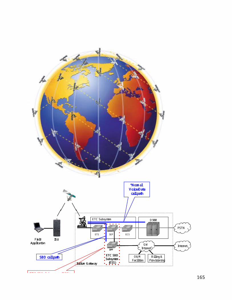
Symbol Characteristics System Specific Value
Paragraph Reference
PSC-SC Maximum burst output power of single carrier AES
8.5 dBW DO-262 2.2.3.1.2.1.2
PSTEP Maximum acceptable step size for controlling AES transmit power
1 dB step, Iridium internal
controlled
DO-262 2.2.3.1.2.1.8
PV Maximum single carrier power for each of NV voice carriers in a multi-carrier capable AES
5.5 dBW DO-262 2.2.3.1.2.1.1
RSC-UD Minimum average single channel user data rate sustainable at a residual packet error rate of 10-6
2.4 kbps DO-262 2.2.3.1.2.2.1.1
MIN Minimum elevation angle for satellite coverage
8.2 deg. DO-262 2.2.3.1.1.1.1
170

Symbol Characteristics System Specific Value
Paragraph Reference
SW Maximum switching time between electronically steered antenna patterns.
N/A DO-262 2.2.3.1.1.9.2
RA Minimum exclusion zone radius necessary for protection of Radio Astronomy
N/A DO-262 2.2.3.1.2.1.6.2
C/M Carrier-to-multipath discrimination ratio measured at the minimum elevation angle
6 dB DO-262 2.2.3.1.1.7
VSWR Maximum Voltage Standing Wave Ratio measured at a single input port of the AES antenna
1.8:1 DO-262 2.2.3.1.1.5
Notes: (1) Line of sight separation angle depends on latitude and specific location of the terminal.(2) In general, this is left to the AES manufacturer as long as other RF performance parameters are within
specifications. Assuming a dual-carrier antenna unit, ND + NV shall be less than or equal to 2.
171

APPENDIX B: ATN OVERVIEW
tbd.
APPENDIX BC: ACRONYMS
AES Aircraft Earth StationAGS AMS(R)S Ground SubsystemARQ Automatic Repeat RequestATC AT CommandBCH Bose, Ray-Chaudhuri, Hocquenghem (a type of error control code)BER Bit Error RateDL DownlinkDFOA Differential Frequency of ArrivalDTOA Differential Time of Arrival
172

ECS Earth Terminal Controller - Communication SubsystemET Earth TerminalETC Earth Terminal ControllerETS Earth Terminal Controller- Transmission SubsystemFA Field ApplicationFDD Frequency Division DuplexFDMA Frequency Division Multiple AccessFEC Forward Error ControlGES Ground Earth StationGSM Global System for Mobile Communication (Groupe Special Mobile)GSS Gateway SBD SubsystemISC International Switching CenterISDN Integrated Services Digital NetworkISLLC Iridium Satellite LLCISU IRIDIUM Subscriber UnitITU International Telecommunications Union
173

kbps Kilobits-per-second ksps Kilosymbols-per-second LBT L-band TransceiverMCF Master Control FacilityMMA Main Mission AntennaMO Mobile OriginatedMOC Message Origination ControllerMOMSN Mobile Originated Message Sequence NumberMSN Message Sequence NumberMT Mobile TerminatedMTMSN Mobile Terminated Message Sequence NumberNGSS Next Generation Satellite SystemPLMN Public Land Mobile NetworkPSDN Public Switched Data NetworkPSTN Public Switched Telephone NetworkRUDICS Router-Based Unrestricted Digital Interworking Connectivity Solution
174

SBD Short Burst DataSEP SBD ETC ProcessorSIM Subscriber Information ModuleSNOC Satellite Network Operation CenterSNSDU Subnetwork Service Data UnitSPP SBD Post ProcessorSSD SBD Subscriber DeviceSSS Switching SubsystemSV Space VehicleTDD Time Division DuplexTDMA Time Division Multiple AccessTTAC Telemetry Tracking and Control/CommandUL UplinkVA Vendor Application
175