irc — mechanical - iccsafe.org · this creates a severe contradiction between the irc and ......
TRANSCRIPT

2015 GROUP A PROPOSED CHANGES TO THE I-CODES MEMPHIS COMMITTEE ACTION HEARINGS
April 19–28, 2015 Memphis Cook Convention Center Memphis, Tennessee
IRC — Mechanical

First Printing
Publication Date: March 2015
Copyright © 2015 By
International Code Council, Inc.
ALL RIGHTS RESERVED. This 2015-2017 Code Development Cycle, Group A (2015) Proposed Changes to the 2015 International Codes is a copyrighted work owned by the International Code Council, Inc. Without advanced written permission from the copyright owner, no part of this book may be reproduced, distributed, or transmitted in any form or by any means, including, without limitations, electronic, optical or mechanical means (by way of example and not limitation, photocopying, or recording by or in an information storage retrieval system). For information on permission to copy material exceeding fair use, please contact: Publications, 4051 West Flossmoor Road, Country Club Hills, IL 60478 (Phone 1-888-422-7233). Trademarks: “International Code Council,” the “International Code Council” logo are trademarks of the International Code Council, Inc.
PRINTED IN THE U.S.A.

2015 GROUP A – PROPOSED CHANGES TO THE INTERNATIONAL RESIDENTIAL CODE –
PLUMBING/MECHANICAL
PLUMBING/MECHANICAL CODE COMMITTEE Travis Lindsey, MCP, Chair Senior Plans Examiner City of Scottsdale Scottsdale, AZ Clarence Lee Milligan, MCP, Vice Chair Assistant Township Manager Upper Providence Township Oaks, PA Charles “Chuck” Atkinson, CBO Building Codes Director Beaufort County, South Carolina (IAS Accredited) Beaufort, SC Marguerite Carroll Regional Regulatory Services Manager Underwriters Laboratories San Jose, CA Carl Chretien, CGP, CGB, CAPS Rep: National Association of Home Builders President Chretien Construction Saco, ME Michael Cudahy Codes and Training Specialist Plastic Pipe and Fittings Association Glen Ellyn, IL Tim Cunningham Rep: National Association of Home Builders President Cunningham Electrical Svc Inc Elkview, WV Pennie L. Feehan, CPI & CMI Rep: Copper Development Association Owner Pennie L. Feehan Consulting Palm Springs, CA
Thomas Polino Plumbing Subcode Official West Windsor Township West Windsor, NJ Stanley Richardson Rep: National Association of Home Builders Richardson Construction Dalton, GA Paul W. Roebuck, Sr. Rep: Texas Professional Real Estate Inspectors Assoc. President and Inspector TexaSpec Inspections and Building Consultants Montgomery, TX Loren Swanson Rep: National Association of Home Builders Southern Michigan Co. Jackson, MI Staff Secretariat: Fred Grable, PE Senior Staff Engineer - Plumbing International Code Council Central Regional Office Country Club Hills, IL Gregg Gress Senior Technical Staff International Code Council Central Regional Office Country Club Hills, IL
ICC COMMITTEE ACTION HEARINGS ::: April, 2015 RM1

TENTATIVE ORDER OF DISCUSSION 2015 PROPOSED CHANGES TO THE
INTERNATIONAL RESIDENTIAL CODE (MECHANICAL)
The following is the tentative order in which the proposed changes to the code will be discussed at the public hearings. Proposed changes which impact the same subject have been grouped to permit consideration in consecutive changes. Proposed change numbers that are indented are those which are being heard out of numerical order. Indentation does not necessarily indicate that one change is related to another. Proposed changes may be grouped for purposes of discussion at the hearing at the discretion of the chair. Note that some RM code change proposals may not be included on this list, as they are being heard by another committee.
M15-15 Part II RM1-15 RM2-15 RM3-15 RM4-15 RM5-15 RM6-15 RM7-15 RM8-15 RM9-15 RM10-15 RM11-15
M41-15 Part II RM12-15 RM13-15 RM14-15 RM15-15 RM16-15 RM17-15 RM18-15 RM19-15 RM20-15 RM21-15 RM22-15 RM23-15 RM24-15 RM25-15 RM26-15 RM27-15 RM28-15 RM29-15 RM30-15 RM31-15 RM32-15 RM33-15 RM34-15 RM35-15 RM36-15 RM37-15
M109-15 Part III RM38-15
RM39-15 RM40-15 RM41-15 RM42-15 RM43-15 RM44-15 RM45-15 RM46-15 RM47-15 RM48-15 RM49-15 RM50-15 RM51-15 RM52-15 RM53-15 RM54-15
ICC COMMITTEE ACTION HEARINGS ::: April, 2015 RM2

RM 1-15 : M1305.1.4.2-MCMANN3695
RM 1-15M1305.1.4.2
Proponent: Guy McMann, Jefferson County Colorado, representing Colorado Association of Plumbingand Mechanical Officials (CAPMO) ([email protected])
2015 International Residential CodeDelete and substitute as follows:
M1305.1.4.2 Excavations.Pit locations Excavations for appliance installations shall extend to a depth of 6 inches(152 mm) below the appliance and 12 inches (305 mm) on all sides, except that the control side shall have aclearance of 30 inches (762 mm).Appliances installed in pits or excavations shall not come in direct contact with the surrounding soil and shall beinstalled not less than 6 inches (152 mm) above the pit floor. The sides of the pit or excavation shall be held back notless thanf 12 inches (305 mm) from the appliance. Where the depth exceeds 12 inches (305 mm) below adjoininggrade, the walls of the pit or excavation shall be lined with concrete or masonry. Such concrete or masonry shallextend not less than 4 inches (102 mm) above adjoining grade and shall have sufficient lateral load-bearing capacityto resist collapse. Excavation on the control side of the appliance shall extend horizontally not less than 30 inches(762 mm). The appliance shall be protected from flooding in an approved manner.
Reason: The language in the IMC and IFGC is much more complete and concise. This modification completes this section and has all theinformation necessary for a code compliant installation and makes it consistent with the other codes
Cost Impact: Will not increase the cost of constructionThis proposal is strictly editorial in nature and will not cause an increase is cost.
ICC COMMITTEE ACTION HEARINGS ::: April, 2015 RM3

RM 2-15 : M1305.1.4.2-MCMANN4827
RM 2-15M1305.1.4.2
Proponent: Guy McMann, Jefferson County Colorado, representing Colorado Association of Plumbingand Mechanical Officials ([email protected])
2015 International Residential CodeDelete without substitution:
M1305.1.4.2 Excavations. Excavations for appliance installations shall extend to a depth of 6 inches (152 mm) belowthe appliance and 12 inches (305 mm) on all sides, except that the control side shall have a clearance of 30 inches(762 mm).
Reason: This is legacy code language that appeared in 1984 and was incorporated into the 2000 edition of the Residention Code. There is notechnical justification to dig a pit 6 inches below the bottom of any appliance. If there is a water issue in a pit an appliance should not beinstalled in it. This section mandates that a water heater be installed on a stand or be suspended above the floor of a pit. M1305.1.4.1 alreadytakes care of the issue by requiring the appliance to be on a 3 inch pad which is perfectly acceptable provided there are no water issues. Thebottom of the pit is still the ground and M1305.1.4.1 would still apply.
Cost Impact: Will not increase the cost of constructionThis proposal will actully decrease the cost of construction by not requiring excessive digging. It will also not require the purchace or buildingof a stand to support the appliance. labor dollars could be saved by not being required to suspend an appliance.
ICC COMMITTEE ACTION HEARINGS ::: April, 2015 RM4

RM 3-15 : M1401.3-ESCOBAR5735
RM 3-15M1401.3
Proponent: Luis Escobar, representing Air Conditioning Contractors of America([email protected])
2015 International Residential CodeRevise as follows:
M1401.3 Equipment and appliance sizing. Heating and cooling equipment and appliances shall be sized inaccordance with ACCA Manual S or other approved sizing methodologies based on building loads calculated inaccordance with ACCA Manual J or other approved heating and cooling calculation methodologies.
Exception: Heating and cooling equipment and appliance sizing shall not be limited to the capacitiesdetermined in accordance with Manual S where either of the following conditions applies:
1. The specified equipment or appliance utilizes multistage technology or variable refrigerant flowtechnology and the loads calculated in accordance with the approved heating and coolingcalculation methodology are within the range of the manufacturer's published capacities for thatequipment or appliance.
2. The specified equipment or appliance manufacturer's published capacities cannot satisfy both thetotal and sensible heat gains calculated in accordance with the approved heating and coolingcalculation methodology and the next larger standard size unit is specified.
Reason: The exceptions in the 2015 codes were initially introduced because it was not certain that Manual S would complete full revisionprior to the 2015 code's publication. However, ACCA Manual S completed the ANSI consensus revision process in 2014 and is referenced inthe 2015 code. This creates a severe contradiction between the IRC and the national consensus standard it references. The Manual S revision committee that developed the sizing procedures and oversize limits included the manufacturers of multi-stage andvariable refrigerant flow (VRF) equipment. Those limits were revised through the public review process and now allow a greater range ofequipment to be installed for multi-stage and VRF applications. The published Manual S fully covers the proper procedures for multi-stageand VRF technology agreed upon by designers, manufacturers, and energy advocates.
A study published in September 2014 by the National Institute of Standards and Technology, entitled "Sensitivity Analysis of Installation Faultson Heat Pump Performance", found that the energy penalty for over-sizing HVAC equipment could lead to as much as 20% greater energyuse in warm climates. Manual S-2014 however allows a new method of oversizing multi-stage and VRF equipment in cold climates to get thenecessary heating performance, while still maintaining appropriate sizing limits for warm climates. BUT the current exceptions apply acrossthe board and will lead to unjustifiable oversizing that cost energy and money.
Bibliography: [Sensitivity Analysis of Installation Faults on Heat Pump Performance][NIST Technical Note 1848][Domanski, Henderson,Payne][2014][www.acca.org/standards/quality][Understanding ACCA Manual S][ACCA Special Presentation][Luis Eescobar][2014][available upon request [email protected]]
[Residential Equipment Selection][ANSI/ACCA 3 Manual S - 2014][ACCA][2014][www.acca.org/standards/codes]
Cost Impact: Will not increase the cost of constructionSee energy consumption results from NIST Study, specifically single fault: equipment sizing. Energy use can increase by up to 24% ifoversizing is the only installation fault. The effects are greater with additional installation faults (duct leakage, indoor coil airflow, refrigerantunder/over charging, etc.).
ICC COMMITTEE ACTION HEARINGS ::: April, 2015 RM5

RM 4-15 : M1411.1-FISCHER5582
RM 4-15M1411.1
Proponent: Mike Fischer, representing the Responsible Refrigerants Codes Council([email protected])
2015 International Residential CodeRevise as follows:
M1411.1 Approved refrigerantsRefrigerants. Refrigerants used in direct refrigerating systems shall conform to theapplicable provisions of ANSI/ASHRAE 34.Section 1103 of the International Mechanical Code.
Reason: The current requirements of M1411.1 in the IRC Mechanical Chapter are not accurate and appropriate- the use of the word"approved" in the section heading is not necessary; the inclusion of the term "direct" leaves no guidance on refreigerants used in indirectsystems, and the reference to ANSI/ASHRAE 34 is incomplete because ASHRAE 15 is not also referenced. the simplest solution to clean upthis section of the code is to replace the existing text and refer to the IMC.
Cost Impact: Will not increase the cost of constructionThe proposal is a clarification of existing requirements.
ICC COMMITTEE ACTION HEARINGS ::: April, 2015 RM6

RM 5-15 : M1411.6.1 (New)-AHERN5275
RM 5-15M1411.6.1 (New)
Proponent: Howard Ahern, representing Airex Mfg. ([email protected])
2015 International Residential CodeAdd new text as follows:
M1411.6.1 Refrigerant line insulation protection Refrigerant Piping insulation exposed to weather shall be protectedfrom damage, including that caused by sunlight, moisture, equipment maintenance and wind. Adhesive tape shall notbe considered as a means of protection.
Reason: This code change clarifies that the Refrigerant vapor (suction) line insulation complying with M1411.6 needs to be protected when itis exposed outdoors. There has been confusion from Builders, inspectors and contractors that manufactures marking U.V. on the pipeinsulation was all that was needed to protect outdoor Refrigerant vapor (suction) line insulation. The majority of Pipe InsulationManufactureres for Refrigerant vapor (suction) line insulation already have stated in their technical papers or installation instructions thatwhen using their insulation outdoors it must be protected from UV, weather and other damage such as rodents and birds and that they offeronly a limited UV resistance. No elastomeric foam is truly UV resistant.The damage can also be caused by not only U.V, moisture, wind and damage from equipment maintenance but also oxidation. All thesefactors will permanently damage the insulations external surface permeability and seriously impact the insulation thermal conductivity whichwill impact the heating or cooling systems efficiency and resulting in higher electrical cost as the compressor must work harder tocompensate for the temperature difference which can lead to a shorter life span of the equipment.
Adhesives break down due to bacteria and moisture, removal of Adhesives tape would destroy the external surface permeability of theinsulation required in M1411.6
Cost Impact: Will not increase the cost of constructionThis code change will not increase cost of construction in jurisdictions that have adopted the 2102 or the 2015 IECC. Most jurisdictions by2018 should have adopted one of the IECC codes. This would only be a cost increase to jurisdictions that have not adopted the 2102 or the2015 IECC. The majority of pipe insulation manufactures already state in their technical papers or instructions that when using their insulationoutdoors it must be protected from weather.
ICC COMMITTEE ACTION HEARINGS ::: April, 2015 RM7

RM 6-15M1411.7.1 (New), Chapter 44
Proponent: Howard Ahern, representing Airex Mfg. ([email protected])
2015 International Residential CodeAdd new text as follows:
M1411.7.1 Exterior wall penetration. Refrigerant piping shall be isolated by a vibration isolator and supported atexterior wall penerations. Vibration isolators shall comply with ASTM E331.
Add new standard(s) as follows: ASTM E331- 00(2009) Standard Test Method for Water Penetration of Exterior Windows, Skylights, Doors, andCurtain Walls by Uniform Static Air Pressure Difference
Reason: This code change is needed to create consistency for installation with this code and Equipment Manufactureres installationinstructions for isolation of refrigerant piping to prevent vibration damage. Refrigerant piping must be isolated and supported to eliminatevibration transfer to the exterior wall specifically from the penetration of refrigerant piping. The majority of Equipment ManufactureresInstallation Instructions have for the last 4 years already required isolation of the refrigerant piping in their installation instructions to preventvibration damage and for noise reduction. Isolation of the piping is also needed to prevent damage to the piping from contact with hardsurfaces and to eliminate stress from vibration which can cause piping and joint fatigue that could lead to leaking refrigerant.The Exterior wall penetration is a critical space due to its close proximity to the equipment and that it is the first wall penetrated by refrigerantpiping in the vast majority of installations.
The only sure way to cut off the path of problematic vibration and eliminate the transference of vibration to the structure is with a VibrationIsolator with the piping supported at the point of penetration to avoid any contact with wall building materials.
Vibration will take the path of least resistance. If the piping is not isolated, then unwanted vibration will transfer through to the wall. VibrationIsolators contain resilient material that absorb the vibration energy and isolate the piping. There are already many materials and productsbeing used in construction for piping isolation.
Trying to repair or retrofitting for vibration problems after complaints arise, is often far more expensive than an original installation.
The exterior wall penetration is often overlooked as a vibration path. Substantial acoustic energy can pass through a small opening in a wall. Reciprocating compressors mainly cause this vibration energy. From a distributing rattle or asking "why is my wall buzzing" every time theequipment starts to occupants perturbed by a "humming " noise, the problems with vibration transmission to the wall from refrigerant lines canbe a constant problem for occupants.
Installation of these isolators when installed must not allow water penetration into the exterior wall and must meet ASTM E331 Standard TestMethod for Water Penetration _____________________________________________________________________________________
Reference R703.1.1 Exterior wall coverings
R703.1.1 Water resistance. The exterior wall envelope shall be designed and constructed in a manner that prevents the accumulation ofwater within the wall assembly by providing a water-resistant barrier behind the exterior veneer as required by Section R703.2 and a meansof draining to the exterior water that enters the assembly. Protection against condensation in the exterior wall assembly shall be provided inaccordance with Section R702.7 of this code.
Exceptions: A weather-resistant exterior wall envelope shall not be required over concrete or masonry walls designed in accordance withChapter 6 and flashed in accordance with Section R703.4 or R703.8.
Compliance with the requirements for a means of drainage, and the requirements of Sections R703.2 and R703.4, shall not be required for anexterior wall envelope that has been demonstrated to resist wind-driven rain through testing of the exterior wall envelope, including joints,penetrations and intersections with dissimilar materials, in accordance with ASTM E 331 under the following conditions
Exterior wall envelope test assemblies shall include at least one opening, one control joint, one wall/eave interface and one wall sill. All testedopenings and penetrations shall be representative of the intended end-use configuration.
Exterior wall envelope test assemblies shall be at least 4 feet by 8 feet (1219 mm by 2438 mm) in size.
Exterior wall assemblies shall be tested at a minimum differential pressure of 6.24 pounds per square foot (299 Pa).
Exterior wall envelope assemblies shall be subjected to the minimum test exposure for a minimum of 2 hours. The exterior wall envelopedesign shall be considered to resist wind-driven rain where the results of testing indicate that water did not penetrate control joints in theexterior wall envelope, joints at the perimeter of openings penetration or intersections of terminations with dissimilar materials.
____________________________________________________________________________________
*"An isolation system is the best inexpensive insurance against unwanted vibration."
The International Mechanical Code and Uniform Mechanical Code both recognize the problems associated with piping vibration.
ICC COMMITTEE ACTION HEARINGS ::: April, 2015 RM8

RM 6-15 : M1411.7.1 (New)-AHERN4794
*Vibration Isolation by Robert Simmons, P.E., ASHRAE Journal 2009
Cost Impact: Will increase the cost of constructionNegligible cost increase, as The International Mechanical Code and the Uniform Mechanical Code already require designing and installingrefrigerant piping to address vibration. A major percentage of any increased cost has already been absorbed by this requirement. Themajority of Equipment Manufactureres already require isolation of the refrigerant piping in their installation instructions to prevent vibration.Again, any increased cost has already been absorbed by the aforementioned installation requirement.There are many products on the market that can be installed for this requirement. Many Builders have already been installing products forvibration isolation and many Contractors building with pressure testing (blower door) have been addressing this penetration area with betterinstallation including isolation. As there are a variety of isolating materials and systems to provide isolation, it is a minor increase inconstruction cost but it is a significant savings to Home Owners and Builders, as trying to repair vibration problems after complaints is oftenvery costly.
Analysis: A review of the standard proposed for inclusion in the code, ASTM E331, with regard to the ICC criteria for referenced standards(Section 3.6 of CP#28) will be posted on the ICC website on or before April 2, 2015.
ICC COMMITTEE ACTION HEARINGS ::: April, 2015 RM9

RM 7-15M1416 (New), M1416.1 (New)
Proponent: Mark Metzner, representing Self ([email protected]); Muktha Tumkur([email protected])
2015 International Residential CodeAdd new text as follows:
SECTION M1416 GROUND SOURCE HEAT PUMP SYSTEMS
M1416.1 Design and installation. The design and installation of ground source heat pump systems shall conform toANSI/CSA C448.
Reason: The CSA C448 is an ANSI designated bi-national consensus Standard for the design and installation of ground source heat pumpsystems. The Standard includes performance based criteria that provide a consistent application of requirements and best practicesthroughout the United States and Canada. This Standard will ensure that stakeholders in the ground source heat pump systems marketsector will supply and receive heating / cooling systems that perform to design efficiency expectations and deliver tru, long-term value. ThisStandard has been developed by a bi-national Technical Committee which comprised of the industry's leaders and it provides a strongfoundation for increased market penetration of this technology into the HVAC market.The Standard harmonizes the differences between existing resources, simplifies referencing in regulations and contracts, incorporates thelatest advancements, clarifies compliance using standards language, and provides credibility through an accredited neutral standardsdevelopment process.
This Standard includes performance based minimum requirements for industrial, commercial, institutional and residential applications andaddresses the following items related to ground source heat pump systems:
- equipment and material selection
- site survey - geological and hydrogeological
open and closed loop ground source heat pump system design / engineering
- direct expansion (DX) systems
- installation
- testing and verification
- documentation
- commissioning and decommissioning
The Standard will apply to all ground source heat pump systems using external building heat exchangers as a thermal source or sink for heating and cooling, with or without a supplementary heating or cooling source. External building heat exchangers that will be covered by thisStandard include:
- ground heat exchangers - vertical and horizontal;
- open-loop systems - drilled well and surface water;
- submerged closed loop systems - fresh water and sea water;
- standing colum wells
This Standard applies to new and retrofit installations in industrial, commercial, institutional and residential applications and includes thermalenergy storage systems.
The bi-national Committee consisted of representatives from the following industry associations:
- American Society for Heating, Refrigeration and Air Conditioning Engineers (ASHRAE)
- Geothermal Exchange Organization (GEO)
- International Ground Source Heat Pump Association (IGSPHA)
- International Ground Source Heat Pump Association Canada (IGSPHA - Canada)
- National Ground Water Association (NGWA)
- Plastics Pipe Institute (PPI)
- Geothermal National & International Initiative (GEONII)
- Heating, Refrigeration and Air Conditioning Institute of Canada (HRAI)
Cost Impact: Will not increase the cost of constructionThe code change proposal will not increase the cost of constructin of ground source heat pump systems.
ICC COMMITTEE ACTION HEARINGS ::: April, 2015 RM10

RM 7-15 : M1416 (New)-METZNER5517
Justification:
Currently, a US standard for the design and installation of ground source heat pump systems, similar to the C448, does not exist. The C448is a system for the design and installation of ground source heat pump systems and it inlcudes requirements and best practices related to theinstallation of these systems. The systems would include pumps, pipe, grout etc., which most likely have manufacturing requirements andcertification requirements within other standards, but that is not within our scope. The C448 is not a certification standard for anymanufactured goods.
The C448 is generally a performance based standard which contains design requirements and best practices typically accepted and usedcurrently by US and Canadian designers. Ground source heat pump systems that adhere to C448 will be properly designed and installed tothe expectation of the owner or end user and as such will represent the minimum baseline performance of such systems. In most cases,alternate materials and installation methods are allowed. Also, in some cases, alternate innovative materials are allowed if reviewed andapproved by an engineer.
ICC COMMITTEE ACTION HEARINGS ::: April, 2015 RM11

RM 8-15 : M1502.3 (New)-BALLANCO3701
RM 8-15M1502.3 (New)
Proponent: Julius Ballanco, JB Engineering and Code Consulting, P.C., representing In-O-VateTechnologies, Inc ([email protected])
2015 International Residential CodeAdd new text as follows:
M1502.3 Make-up air for tight construction. Make-up air shall be provided for clothes dryers where the airinfiltration rate is known to be less than 0.4 air changes per hour (ACH). Make-up air shall be provided by a duct thatcommunicates with the outdoors, a ventilated crawl space, or a ventilated attic space and such duct shall have across sectional area not less than that of a 4 inch round duct. The make-up air duct shall open into the room in whichthe clothes dryer is located. Make-up air duct inlets shall be provided with a screen having a mesh size not less than¼ inch and not greater than ½ inch. The make-up air inlet shall be equipped with an air admitting damper that opensduring the operation of the clothes dryer.
Exception: Condensing dryers shall not require make-up air.
Reason: Today homes are much more tightly constructed, creating an inadequate condition for the proper operation of a clothes dryer. Theexhaust rate for a residential dryer ranges from 125 to 200 cfm with newer dryers favoring 200 cfm.When the air infiltration rate drops to less than 0.4 air changes per hour, this creates a condition of inadequate make-up for the clothes dryer.When there is inadequate ambient air to pull from, the dryer is starved and not capable of efficiently drying the clothes any longer. Thisextends the length of time for the dryer cycle wasting energy. It also reduce the life of the dryer since the fan is attempting to exhaust air thatis not available.
Many clothes dryers are located in the basement of a home. When located in the basement, they have the available air in the basement asmake-up air for exhausting the moisture. If a basement in 25 feet by 25 feet with an 8 foot ceiling, there is 5,000 cubic feet of available air.However, with an air exchange rate of 0.4, the available air for exhaust is 2000 cubic feet. That translates to 33.3 cfm of air. This means thatthe dryer has to draw air from other locations in order to properly operate, potentially pulling it from other unsafe sources.
Outside air is normally required by combustion air when the air infiltration rate is less than 0.4 as identified in Section G2407.5. This codechange is consistent by requiring make-up air when the air exchange rate is below this value. The amount of air required for combustion air isnormally less than the amount of make-up air for a dryer exhaust. An 80,000 Btu/hr furnace only requires between 16.6 and 26.6 cfm forcombustion air, whereas the dryer requires between 125 and 200 cf
With a 4 inch duct, the make-up air can be provided at an acceptable rate. Furthermore, the fan in the clothes dryer would draw the make-upair through the make-up air duct.
A screened air admitting damper or equivalent device is necessary to prevent outside air from entering the home when the clothes dryer isnot in use. The screen dimension are taken from Table 401.5 of the IMC for residential occupancies. The air admitting damper also preventsthe loss of conditioned air when the dryer is not in use.
Cost Impact: Will increase the cost of constructionThere will be an increase cost to install a make up air duct.
ICC COMMITTEE ACTION HEARINGS ::: April, 2015 RM12

RM 9-15 : M1502.3-BALLANCO4119
RM 9-15M1502.3
Proponent: Julius Ballanco, JB Engineering and Code Consulting, P.C., representing In-O-VateTechnologies ([email protected])
2015 International Residential CodeRevise as follows:
M1502.3 Duct termination. Exhaust ducts shall terminate on the outside of the building. Exhaust duct terminationsshall be in accordance with the dryer manufacturer's installation instructions. If the manufacturer's instructions do notspecify a termination location, the exhaust duct shall terminate not less than 3 feet (914 mm) in any direction fromopenings into buildings. Exhaust duct terminations shall be equipped with a backdraft damper. Screens shall not beinstalled at the duct termination. Exhaust duct penetrations of exterior wall and roof assemblies shall be sealed air-tight to prevent the dryer exhaust from re-entering the building.
Reason: This change clarifies that the dryer exhaust must vent to the outside without the possibility of having the dryer exhaust return to thebuilding. In some regions, friction-fitting a ducts' end into a roof cap appears to still be acceptable. This change adds the language to require apositive leak-proof assembly that will prevent the dryer exhaust from reentering the building. The high humidity of the dryer exhaust cancause all sorts of problems within the building elements if the dryer exhaust can reenter the building. Humidity control is an important part ofany building design. As such, humid lint-laden air should never be given a path to enter the building after being exhausted.
Cost Impact: Will not increase the cost of constructionThis change clarifies the intent of the code.
ICC COMMITTEE ACTION HEARINGS ::: April, 2015 RM13

RM 10-15M1502.3
Proponent: Julius Ballanco, JB Engineering and Code Consulting, P.C., representing In-O-VateTechnologies ([email protected])
2015 International Residential CodeRevise as follows:
M1502.3 Duct termination. Exhaust ducts shall terminate on the outside of the building. Exhaust duct terminationsshall be in accordance with the dryer manufacturer's installation instructions. If the manufacturer's instructions do notspecify a termination location, the exhaust duct shall terminate not less than 3 feet (914 mm) in any direction fromopenings into buildings. Exhaust duct terminations shall be equipped with a backdraft damper. Screens shall not beinstalled at the duct termination. Dryer exhaust duct terminations shall, by design, provide access for cleaning theexhaust duct.
Reason: The routine cleaning of the dryer exhaust ducts minimizes the potential for a fire in the duct as well as increasing the efficiency ofthe appliance. Duct cleaning services now provide this service for dryer exhaust ducts using a wand and brush. Many duct cleaning servicecompanies enter the dryer exhaust duct through the duct termination. This offers an easy access to the dryer exhaust duct system. If aproper dryer exhaust terminal is not provided that allows ease of access, some companies have been known to wrongly remove thetermination lid or cover creating a potential leak situation.
ICC COMMITTEE ACTION HEARINGS ::: April, 2015 RM14

RM 10-15 : M1502.3-BALLANCO4122
Cost Impact: Will increase the cost of constructionThe exhaust terminal may cost more.
ICC COMMITTEE ACTION HEARINGS ::: April, 2015 RM15

RM 11-15 : M1502.3.1-BALLANCO4125
RM 11-15M1502.3.1 (New)
Proponent: Julius Ballanco, JB Engineering and Code Consulting, P.C., representing In-O-VateTechnologies ([email protected])
2015 International Residential CodeAdd new text as follows:
M1502.3.1 Exhaust termination outlet and passageway size. The passageway of dryer exhaust duct terminalsshall be undiminished in size and shall provide an open area of not less than 12.5 square inches (8,065 sq mm).
Reason: The allowable (calculated) length of the dryer exhaust duct is based on an open (non-restrictive) exhaust terminal. Some exhaustterminals increase resistance due to their inherent design characteristics (path and final opening size). This results in the dryer exhaust ducthaving to be reduced in length. However, there is no allowance for a reduction in length for a highly resistant vent cap. Short of requiringtesting standards for every vent termination, the code must require a minimum open area of 12.5 sq. inches which equates to a 4" round duct.The code is very sensitive and detailed as it relates to 90 degree elbows and their respective friction loss but does not prohibit or penalize fortermination hoods that grossly create back pressure, reducing the efficiency of the dryer.The dimension used for the opening in the interior area of the 4 inches duct is rounded to an even number (12.5"). By maintaining the sameopening area throughout the vent terminal, the friction resistance in vent caps can be greatly reduced.
Video Links:
www.youtube.com/watch?v=5KnRp3eXNbk
http://youtu.be/ZL2zV1-GjdI?t=50s
Cost Impact: Will increase the cost of constructionThe cost of the vent terminal may be higher.
ICC COMMITTEE ACTION HEARINGS ::: April, 2015 RM16

RM 12-15M1502.4.2
Proponent: Julius Ballanco, JB Engineering and Code Consulting, P.C., representing In-O-VateTechnologies ([email protected])
2015 International Residential CodeRevise as follows:
M1502.4.2 Duct installation. Exhaust ducts shall be supported at intervals not to exceed 12 feet (3658 mm) andshall be secured in place. The insert end of the duct shall extend into the adjoining duct or fitting in the direction ofairflow. Exhaust duct joints shall be sealed in accordance with Section M1601.4.1 and shall be mechanicallyfastened. Ducts shall not be joined with screws or similar fasteners that protrude more than 1 /
8 inch (3.2 mm) into the
inside of the duct. Where dryer exhaust ducts are enclosed in wall or ceiling cavities, such cavities shall have a leastdimension of not less than 4.25 inches (108 mm). Round ducts shall not be deformed.
Reason: The dryer exhaust duct must remain round in shape to reduce friction loss in the duct system. The length of the duct andtermination are based on friction loss for round duct, not oval duct. The length of the dryer exhaust duct would have to be reduced if the 4inch duct was oval in shape. In addition to the reduction in efficiency, the oval pipe creates a difficult connection for the consumer to make tothe dryer exhaust transition hose. A 1 inch furring strip (1x2) can be added to a 2 x 4 stud providing the 4.25 inches of space. In most cases, this "mechanical" wall is busy withother trades (plumbing drainage and vent stacks, gas piping, electric service, laundry services and water piping). A 4.25 inch space willbenefit all of the trades working within that space. The minimum space required to keep the dryer exhaust duct round is 4.125 inches. Thisdimension could also be referenced here, however, most contractors
ICC COMMITTEE ACTION HEARINGS ::: April, 2015 RM17

ICC COMMITTEE ACTION HEARINGS ::: April, 2015 RM18

ICC COMMITTEE ACTION HEARINGS ::: April, 2015 RM19

RM 12-15 : M1502.4.2-BALLANCO4117
Cost Impact: Will increase the cost of constructionThere is an added cost for furring strips on a 2 x 4 wall.
ICC COMMITTEE ACTION HEARINGS ::: April, 2015 RM20

RM 13-15 : M1502.4.2.1 (New)-HARPENAU4553
RM 13-15M1502.4.2.1 (New)
Proponent: Rick Harpenau, In-O-Vate Technologies, representing In-O-Vate Technologies([email protected])
2015 International Residential CodeAdd new text as follows:
M1502.4.2.1 Exhaust termination pathways. . Dryer exhaust duct terminal pathways that cause a change indirection of air flow between 45 and 90 degrees shall have an area not less than 20 percent larger that the crosssectional area of the exhaust duct served. Dryer exhaust duct terminal pathways that cause a change in direction ofair flow greater than 90 degrees shall have an area not less than 30 percent larger than the cross sectional area of theexhaust duct served. Exhaust duct terminal passageways shall maintain throughout an area of not less than 12.5square inches (8,065 sq mm).
Reason: The code is very sensitive and detailed as it relates to 90 degree elbows and their respective friction loss but does not prohibit orpenalize for termination hoods that grossly create back pressure, reducing the efficiency of the dryer. There are wall vents and roof vents onthe market that with minimal testing equipment show clearly they create as much back pressure as 3 and 4 elbows. Short of requiring testingstandards for every vent termination, the council should consider language whereby the passageway increases in size to make up for thefriction causing bends. If this addition to the codes makes sense, actual calculations can be provided. Bottom line, treat terminations thesame as elbows and run lengths. Video Links:
www.youtube.com/watch?v=5KnRp3eXNbk
http://youtu.be/ZL2zV1-GjdI?t=50s
Cost Impact: Will increase the cost of constructionThe increase size may result in a higher cost.
ICC COMMITTEE ACTION HEARINGS ::: April, 2015 RM21
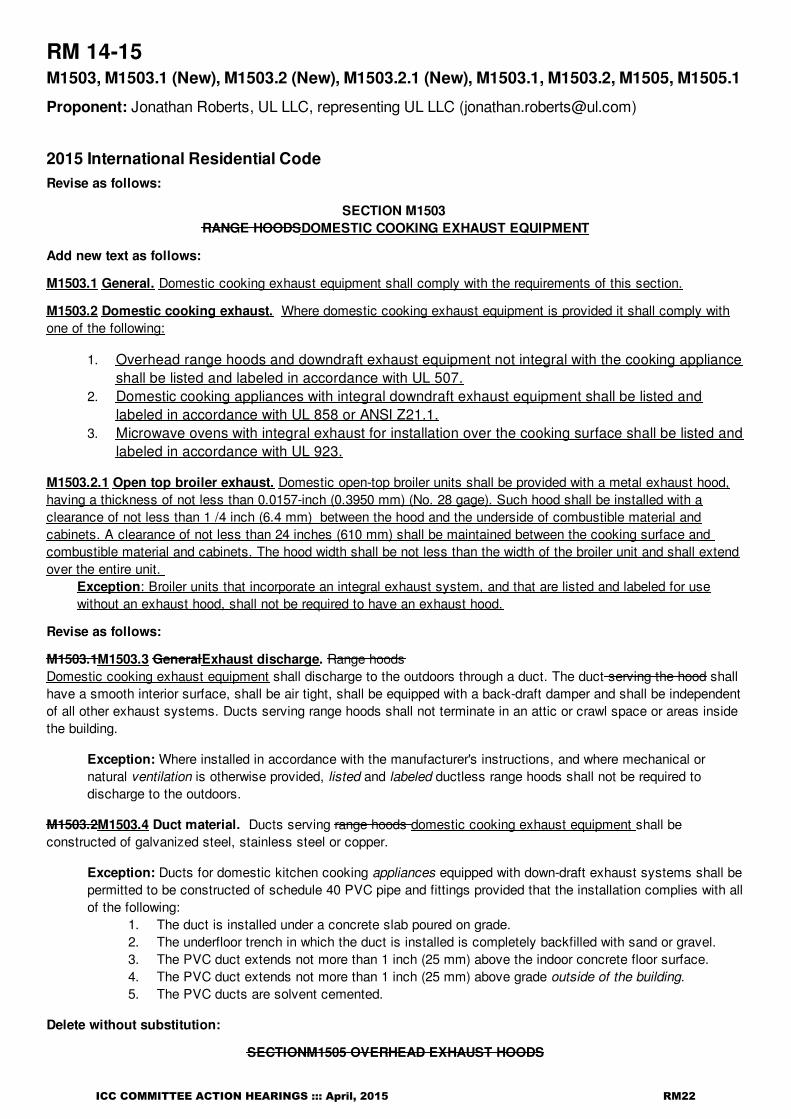
RM 14-15M1503, M1503.1 (New), M1503.2 (New), M1503.2.1 (New), M1503.1, M1503.2, M1505, M1505.1
Proponent: Jonathan Roberts, UL LLC, representing UL LLC ([email protected])
2015 International Residential CodeRevise as follows:
SECTION M1503 RANGE HOODSDOMESTIC COOKING EXHAUST EQUIPMENT
Add new text as follows:
M1503.1 General. Domestic cooking exhaust equipment shall comply with the requirements of this section.
M1503.2 Domestic cooking exhaust. Where domestic cooking exhaust equipment is provided it shall comply withone of the following:
1. Overhead range hoods and downdraft exhaust equipment not integral with the cooking applianceshall be listed and labeled in accordance with UL 507.
2. Domestic cooking appliances with integral downdraft exhaust equipment shall be listed andlabeled in accordance with UL 858 or ANSI Z21.1.
3. Microwave ovens with integral exhaust for installation over the cooking surface shall be listed andlabeled in accordance with UL 923.
M1503.2.1 Open top broiler exhaust. Domestic open-top broiler units shall be provided with a metal exhaust hood,having a thickness of not less than 0.0157-inch (0.3950 mm) (No. 28 gage). Such hood shall be installed with aclearance of not less than 1 /4 inch (6.4 mm) between the hood and the underside of combustible material andcabinets. A clearance of not less than 24 inches (610 mm) shall be maintained between the cooking surface and combustible material and cabinets. The hood width shall be not less than the width of the broiler unit and shall extendover the entire unit.
Exception: Broiler units that incorporate an integral exhaust system, and that are listed and labeled for usewithout an exhaust hood, shall not be required to have an exhaust hood.
Revise as follows:
M1503.1M1503.3 GeneralExhaust discharge. Range hoodsDomestic cooking exhaust equipment shall discharge to the outdoors through a duct. The duct serving the hood shallhave a smooth interior surface, shall be air tight, shall be equipped with a back-draft damper and shall be independentof all other exhaust systems. Ducts serving range hoods shall not terminate in an attic or crawl space or areas insidethe building.
Exception: Where installed in accordance with the manufacturer's instructions, and where mechanical ornatural ventilation is otherwise provided, listed and labeled ductless range hoods shall not be required todischarge to the outdoors.
M1503.2M1503.4 Duct material. Ducts serving range hoods domestic cooking exhaust equipment shall beconstructed of galvanized steel, stainless steel or copper.
Exception: Ducts for domestic kitchen cooking appliances equipped with down-draft exhaust systems shall bepermitted to be constructed of schedule 40 PVC pipe and fittings provided that the installation complies with allof the following:
1. The duct is installed under a concrete slab poured on grade.2. The underfloor trench in which the duct is installed is completely backfilled with sand or gravel.3. The PVC duct extends not more than 1 inch (25 mm) above the indoor concrete floor surface.4. The PVC duct extends not more than 1 inch (25 mm) above grade outside of the building.5. The PVC ducts are solvent cemented.
Delete without substitution:
SECTIONM1505 OVERHEAD EXHAUST HOODS
ICC COMMITTEE ACTION HEARINGS ::: April, 2015 RM22

RM 14-15 : M1503-ROBERTS5726
M1505.1 General. Domestic open-top broiler units shall have a metal exhaust hood, having a minimum thickness of0.0157-inch (0.3950 mm) (No. 28 gage) with 1 /
4 inch (6.4 mm) clearance between the hood and the underside of
combustible material or cabinets. A clearance of not less than 24 inches (610 mm) shall be maintained between thecooking surface and the combustible material or cabinet. The hood shall be not less than the width of the broiler unit,extend over the entire unit, discharge to the outdoors and be equipped with a backdraft damper or other means tocontrol infiltration/exfiltration when not in operation. Broiler units incorporating an integral exhaust system, and listedand labeled for use without an exhaust hood, need not have an exhaust hood.
Reason: This proposal accomplishes the following:
1. Changes the name of Section M1503 from Range Hoods to Domestic Cooking Exhaust Equipment, which more accurately reflectsthe duct, makeup air, and exhaust air requirements in the section.
2. Adds a charging paragraph for the Section to M1503.1.3. Describes the listing standards used to investigate the various types of exhaust equipment in Section M1503.2.4. Relocates Section M1505.1 for open top broilers to section M1503.2.1.5. Makes editorial revisions for clarity.
Cost Impact: Will not increase the cost of constructionIt is primarily editorial in nature.
ICC COMMITTEE ACTION HEARINGS ::: April, 2015 RM23
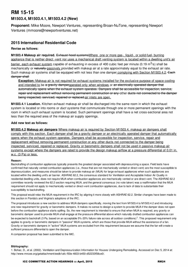
RM 15-15M1503.4, M1503.4.1, M1503.4.2 (New)
Proponent: Mike Moore, Newport Ventures, representing Broan-NuTone, representing NewportVentures ([email protected])
2015 International Residential CodeRevise as follows:
M1503.4 Makeup air required. Exhaust hood systemsWhere one or more gas-, liquid-, or solid-fuel- burningappliance that is neither direct -vent nor uses a mechanical draft venting system is located within a dwelling unit's airbarrier, each exhaust system capable of exhausting in excess of 400 cubic feet per minute (0.19 m3/s) shall bemechanically or naturally passively provided with makeup air at a rate approximately equal to the exhaust air rate.Such makeup air systems shall be equipped with not less than one damper complying with Section M1503.4.2. Eachdamper shall
Exception: Makeup air is not required for exhaust systems installed for the exclusive purpose of space coolingand intended to be a gravity damperoperated only when windows or an electrically operated damper thatautomatically opens when the exhaust system operates. Dampers shall be accessible for inspection, service,repair and replacement without removing permanent construction or any other ducts not connected to the damperbeing inspected, serviced, repaired or replaced.air inlets are open.
M1503.4.1 Location. Kitchen exhaust makeup air shall be discharged into the same room in which the exhaustsystem is located or into rooms or duct systems that communicate through one or more permanent openings with theroom in which such exhaust system is located. Such permanent openings shall have a net cross-sectional area notless than the required area of the makeup air supply openings.
Add new text as follows:
M1503.4.2 Makeup air dampers Where makeup air is required by Section M1503.4, makeup air dampers shallcomply with this section. Each damper shall be a gravity damper or an electrically operated damper that automaticallyopens when the exhaust system operates. Dampers shall be accessible for inspection, service, repair andreplacement without removing permanent construction or any other ducts not connected to the damper beinginspected, serviced, repaired or replaced. Gravity or barometric dampers shall not be used in passive makeup airsystems except where the dampers are rated to provide the design makeup airflow at a pressure differential of 0.01 in.w.c. (3 Pa) or less.
Reason: Backdrafting of combustion appliances typically presents the greatest danger associated with depressurizing a space. Field tests haveconfirmed that naturally vented combustion appliances (i.e., those that are not mechanically vented or direct-vent) are the most susceptible todepressurization, and measures should be taken to provide makeup air (MUA) for large exhaust appliances when such appliances arelocated within the dwelling unit's air barrier. ASHRAE 62.2, the consensus standard for Ventilation and Acceptable Indoor Air Quality inresidential dwelling units, does not require MUA when combustion appliances are mechanically vented or are direct-vent. The ASHRAE 62.2committee recently reviewed the 62.2 section requiring MUA, and the general consensus (no vote taken) was a reaffirmation that the MUArequirement should not apply to mechanically vented or direct-vent combustion appliances, due to lack of data to substantiate theirsusceptibility to backdrafting.
This proposal would relax the MUA requirement in the IRC by aligning it more closely with ASHRAE 62.2. Similar changes have been made tothis section in Florida's and Virginia's adoptions of the IRC.
The proposal introduces a new section to address MUA dampers specifically, moving the text from M1503.4 to M1503.4.2 and introducingone new requirement for gravity or barometric dampers. It makes no sense to design a system to provide MUA if the damper does not openbefore the combustion appliance starts spilling. So, the new requirement is intended to ensure that when MUA is required, any gravity orbarometric damper used to provide MUA shall engage at the pressure differential above which naturally drafted combustion appliances canbe expected to backdraft (3 Pa, based on an acceptable 5%-20% failure rate across all outdoor conditions)1. This proposed requirement onlyapplies to gravity or barometric dampers in "passive" MUA systems, which are those that provide MUA without the assistance of a fan.Gravity or barometric dampers in "active" MUA systems are excluded from this requirement because we assume that the fan will create asufficient pressure differential to open the damper.
A companion proposal has been submitted to the IMC.
Bibliography: 1. Bohac, D., et al. (2002). Ventilation and Depressurization Information for Houses Undergoing Remodeling. Accessed on Dec 5, 2014 at:http://www.mncee.org/getattachment/eedb1afc-f50e-4833-b450-d52233f58ce0/.
ICC COMMITTEE ACTION HEARINGS ::: April, 2015 RM24

RM 15-15 : M1503.4-MOORE4878
Cost Impact: Will not increase the cost of constructionThis proposal is expected to reduce construction costs by reducing the number of scenarios requiring makeup air for kitchen exhaust.
ICC COMMITTEE ACTION HEARINGS ::: April, 2015 RM25

RM 16-15 : M1503.4-SNYDER4454
RM 16-15M1503.4
Proponent: Janine Snyder, City of Thornton, Colorado, representing Colorado Association of Plumbing &Mechanical Officials (CAPMO) ([email protected])
2015 International Residential CodeRevise as follows:
M1503.4 Makeup air required. Exhaust hood systems capable of exhausting in excess of 400 cubic feet per minute(0.19 m3/s) shall be mechanically or naturally provided with makeup air at a rate approximately equal to the exhaustair rate. Such makeup air systems shall be equipped with not less than one damper. Each damper shall be a gravitydamper or an electrically operated damper that automatically opens when the exhaust system operates. Dampersshall be accessible for inspection, service, repair and replacement without removing permanent construction or anyother ducts not connected to the damper being inspected, serviced, repaired or replaced.
Reason: The proposed change allows the code to capture down draft systems as well and not just apply to hoods.
Cost Impact: Will not increase the cost of constructionThis will allow consistency with all exhaust systems.
ICC COMMITTEE ACTION HEARINGS ::: April, 2015 RM26

RM 17-15 : M1503.4-SNYDER5667
RM 17-15M1503.4
Proponent: Janine Snyder, City of Thornton, Colorado, representing Colorado Association of Plumbing &Mechanical Officials (CAPMO) ([email protected])
2015 International Residential CodeDelete and substitute as follows:
M1503.4 Makeup air required. Exhaust hood systems capable of exhausting in excess of 400 cubic feet per minute(0.19 m3/s) shall be mechanically or naturally provided with makeup air at a rate approximately equal to the exhaustair rate. Such makeup air systems shall be equipped with not less than one damper. Each damper shall be a gravitydamper or an electrically operated damper that automatically opens when the exhaust system operates. Dampersshall be accessible for inspection, service, repair and replacement without removing permanent construction or anyother ducts not connected to the damper being inspected, serviced, repaired or replaced.Exhaust hood systems capable of exhausting in excess of 400 cubic feet per minute (0.19 m3/s) shall bemechanically or naturally provided with makeup air at a rate approximately equal to the exhaust air rate. Such makeupair systems shall be equipped with not less than one damper. Each damper shall be an electrically operated damperthat automatically opens when the exhaust system operates. Dampers shall be accessible for inspection, service,repair and replacement without removing permanent construction or any other ducts not connected to the damperbeing inspected, serviced, repaired or replaced.
Reason: By practice they just don't work unless installed running downhill in the duct which can create a faulty seal within the duct allowingadditional leakage. The whole intent is to have the electronic connection between the hood and damper. Volume dampers are subject to notfully closing when installed in the horizontal run due to wind and interior vs exterior pressure diffentials. Additionally, they can create anunintended opening in the building envelope which is a prohibition in the energy code.
Cost Impact: Will increase the cost of constructionThis will slightly increase the cost of construction by returning to practices. However, the energy cost impact of having an opening into aconditioned structure from the exterior mitigates the increased construction cost.
ICC COMMITTEE ACTION HEARINGS ::: April, 2015 RM27

RM 18-15 : M1503.4-SURRENA5020
RM 18-15M1503.4
Proponent: Donald Surrena, National Association of Home Builders, representing National Associationof Home Builders ([email protected])
2015 International Residential CodeRevise as follows:
M1503.4 Makeup air required. Exhaust hood systems capable of exhausting in excess of 400 cubic feet per minute(0.19 m3/s) shall be mechanically or naturally provided with makeup air at a rate approximately equal to the exhaustair rate that is in excess of 400 cubic feet per minute. Such makeup air systems shall be equipped with not less thanone damper. Each damper shall be a gravity damper or an electrically operated damper that automatically opens whenthe exhaust system operates. Dampers shall be accessible for inspection, service, repair and replacement withoutremoving permanent construction or any other ducts not connected to the damper being inspected, serviced, repairedor replaced.
Exception:
1. Makeup air provisions are not required for dwellings that do not contain naturally vented appliances orsolid fuel- burning appliances.
2. Makeup air provisions are not required for kitchen exhaust systems that are capable of exhausting notgreater than 600 cubic feet per minute (0.28 m3/s) provided that one or more of the following conditions ismet.
3. The floor area within the air barrier of a dwelling unit is not less than 1500 square feet (139 m2), andnatural draft type and mechanical draft type space-heating or water-heating appliances are not locatedwithin the air barrier.
4. The floor area within the air barrier of a dwelling unit is not less than 3000 square feet (279 m2), and natural draft type space-heating or water-heating appliances are not located within the air barrier.
Reason: This proposal makes two functional changes to the makeup air requirements. First, it reduces the makup air requirement to only bethe amount in excess of 400 cfm rather than the entire amount of ehxaust. Second, the change includes exceptions to allow higher exhaustrates for larger homes.As orginially written in the 2015 IRC, section M1503.4 allows range hoods up to 400 cfm to be installed without makup air. It would beconsistent to require makeup air equaling the excess of 400 cfm for larger capacity fans. Essentially, there would be no difference betweenthe effect a 400 cfm fan has on a hous and a 600 cfm fan with 200 cfm of makup air. This would also improve the feasibility and acceptance ofthis code section as well as reduce wasted energy and potential occupant discomfort caused by needlessly introducing excessive amountsof unconditioned air.
This will ultimately improve the feasibility and acceptance of this code section as well as cut down on the amount of wasted energy andpotential occupant discomfort caused by needlessly introducing excessive amounts of unconditioned air.
Cost Impact: Will not increase the cost of constructionHouses meeting the exception will reduce construction cost by at least $150. This savings include not installing an outdoor air supply ductand a gravity damper in addition to the ongoing energy savings to the home owner.
ICC COMMITTEE ACTION HEARINGS ::: April, 2015 RM28

RM 19-15 : M1504.1-ROBERTS5767
RM 19-15M1504.1, M1901.1, M1901.2
Proponent: Jonathan Roberts, UL LLC, representing UL LLC ([email protected])
2015 International Residential CodeDelete without substitution:
M1504.1 Installation of a microwave oven over a cooking appliance. The installation of a listed and labeledcooking appliance or microwave oven over a listed and labeled cooking appliance shall conform to the terms of theupper appliance'slisting and label and the manufacturer's installation instructions. The microwave oven shall conformto UL 923.
Revise as follows:
M1901.1 Clearances. Freestanding or built-in ranges shall have a vertical clearance above the cooking top of not lessthan 30 inches (762 mm) to unprotected combustible material. Reduced clearances are permitted in accordance withthe listing and labeling of the range hoods or appliances. The installation of a listed and labeled cooking appliance ormicrowave oven over a listed and labeled cooking appliance shall be in accordanceovens with Section M1504.1. Theclearances for a domestic open-top broiler unit shall be in accordance with Section M1505.1.integral exhaust.
M1901.2 Cooking appliances. Cooking appliances shall be listed and labeled for household use and shall beinstalled in accordance with the manufacturer's instructions. The installation shall not interfere with combustion air oraccess for operation and servicing. Electric cooking appliances shall comply with UL 1026 or UL 858. Solid-fuel-firedfireplace stoves shall comply with UL 737. Microwave ovens shall comply with UL 923.
Reason: This proposal clarifies installation criteria for microwave ovens with integral exhaust fans that are installed above cooking surfaces.It does this as follows:1. Deletes Section M1504.1. Those requirements primarily deal with clearances, which is covered by Section M1901.1.2. Section M1901.1 was revised to clarify that reduced clearances to combustible material can be done in accordance with the listing andlabeling of the microwave oven with integral exhaust. 3. The reference to microwave ovens complying with UL 923 was moved from deleted Section M1504.1 to Section M1901.2.
Cost Impact: Will not increase the cost of constructionEditorial changes only.
ICC COMMITTEE ACTION HEARINGS ::: April, 2015 RM29

RM 20-15M1506.3, R303.5, R303.5.1, R303.5.2
Proponent: Mike Moore, Newport Ventures, representing Broan-NuTone, representing Newport([email protected])
2015 International Residential CodeRevise as follows:
M1506.3 Exhaust openings. Air exhaust openings shall terminate not less than 3 feet (914 mm) from property lines;3 feet (914 mm) from operable and nonoperable openings into the building and 10 feet (3048 mm) from mechanical airintakes except where the opening is located 3 feet (914 mm) above the air intake.Openings shall comply with Sections R303.5.2 and R303.6.
R303.5 Opening location. Outdoor intake and exhaust openings shall be located in accordance with SectionsR303.5.1 and R303.5.2.
R303.5.1 Intake openings. Mechanical and gravity outdoor air intake openings shall be located not less than 10 feet(3048 mm) from any hazardous or noxious contaminant source, such as vents, chimneys, plumbing vents, streets,alleys, parking lots and loading docks.
For the purpose of this section, the exhaust from dwelling unit toilet rooms, bathrooms, kitchens, and kitchensotherliving space shall not be considered as hazardous or noxious.
Exceptions:1. The 10-foot (3048 mm) separation is not required where the intake opening is located 3 feet (914
mm) or greater below the contaminant source.2. Vents and chimneys serving fuel-burning appliances shall be terminated in accordance with the
applicable provisions of Chapters 18 and 24.3. Clothes dryer exhaust ducts shall be terminated in accordance with Section M1502.3.
R303.5.2 Exhaust openings. Exhaust air shall not be directed onto walkways. Air exhaust openings shall terminatenot less than 3 feet (914 mm) from property lines; 3 feet (914 mm) from operable and nonoperable openings into thebuilding; and 10 feet (3048 mm) from mechanical air intakes.
Exceptions:
1. The 10-foot (3048 mm) separation between intake and exhaust openings is not required where the intakeopening is located 3 feet (914 mm) or greater below the contaminant source.
2. Vents and chimneys serving fuel-burning appliances shall be terminated in accordance with the applicableprovisions of Chapters 18 and 24.
3. Clothes dryer exhaust ducts shall be terminated in accordance with Section M1502.3. 4. Where a combined exhaust and intake terminal is used to separate intake air from exhaust air originating
in living space other than kitchens, a minimum separation distance between these two openings is notrequired provided that the exhaust air concentration within the intake air flow does not exceed 10%, asestablished by the manufacturer of such terminal.
Reason: Combined exhaust/supply terminations are regularly installed with heating and energy recovery ventilators (H/ERVs). Their use reducesbuilding penetrations, labor, and associated system costs. By reducing the number of penetrations, air leakage can also be reduced, resultingin space conditioning energy savings. Further, the durability of the structure can be improved through reducing entry pathways for bulk water.Combined terminations are regularly approved and installed in single family and multifamily dwelling units across the country, andmanufacturer tests have demonstrated that minimum cross-contamination of airflow results from these terminations. There is currently noindustry standard by which to test these units, so we have simply proposed that their performance be verified by the manufacturer, as is thepractice in other areas of the code (M2002.5, R502.7, R502.8.2, R703.11.1.1, R802.7.2, R905.2.6, R1003.15.1, R1003.15.2, G2405.3, etc.).The 10% cross contamination metric is based on language in ASHRAE 62.1 that limits cross contamination of exhaust and supply streams to10% for "air with moderate contaminant concentration, mild sensory-irritation intensity, or mildly offensive odors"; a similar exception exists inthe IMC, Section 514.4. In both the IMC and ASHRAE 62.1, no standard is cited for determining cross-contamination, presumably becausenone yet exists. All exceptions were moved to the exhaust openings section because two of the four exceptions address only exhaustopenings; the other two exceptions apply to both intake and exhaust openings, so could feasibly be located in either section.
Cost Impact: Will not increase the cost of construction
ICC COMMITTEE ACTION HEARINGS ::: April, 2015 RM30

RM 20-15 : M1506.3-MOORE4871
This proposal is expected to reduce construction costs by eliminating the need for a second wall cap and extra ducting that would otherwisebe required to separate intake and exhaust airstreams.
ICC COMMITTEE ACTION HEARINGS ::: April, 2015 RM31

RM 21-15 : M1506.3-SNYDER3285
RM 21-15M1506.3
Proponent: Janine Snyder, representing Plumbing, Mechanical, and Fuel Gas Code Action Committee([email protected])
2015 International Residential CodeDelete and substitute as follows:
M1506.3 Exhaust openings. Air exhaust openings shall terminate not less than 3 feet (914 mm) from property lines;3 feet (914 mm) from operable and nonoperable openings into the building and 10 feet (3048 mm) from mechanical airintakes except where the opening is located 3 feet (914 mm) above the air intake. Openings shall comply withSections R303.5.2 and R303.6.Air exhaust openings shall terminate as follows:
1. Not less than 3 feet (914 mm) from property lines.2. Not less than 3 feet (914 mm) from gravity air intake openings, operable windows and doors..3. Not less than 10 feet (3048 mm) from mechanical air intakes openings except where the exhaust opening
is located not less than 3 feet (914 mm) above the air intake opening. Openings shall comply withSections R303.5.2 and R303.6.
Reason: This section has been misinterpreted because of its poor language and structure. It reads much better in a list format and thenecessary clarifiers "not less than" were added where the code appeared to be requiring an exact distance of 3 or 10 feet. The terms"operable and nonoperable openings" are ambiguous because they could be referring to windows that don't open (inoperable) or grilles andlouvers that have no means of closure. The intent, of course, is simply to regulate the distance to air intake openings, doors and operablewindows. A fixed glass panel can be viewed as an opening, but there is no reason to limit the distance to an exhaust opening from a fixedglass panel. The last requirement relative to mechanical air intakes confused the words "opening" and "intakes," both of which are openings.The revised text cleans up this section with no change in intent.This proposal is submitted by the ICC Plumbing, Mechanical and Fuel Gas Code Action Committee (PMGCAC) The PMGCAC wasestablished by the ICC Board of Directors to pursue opportunities to improve and enhance assigned International Codes or portions thereof.This includes both the technical aspects of the codes and the code content in terms of scope and application of referenced standards. ThePMGCAC has held one open meeting and multiple conference calls which included members of the PMGCAC. Interested parties alsoparticipated in all conference calls to discuss and debate the proposed changes.
Cost Impact: Will not increase the cost of constructionThis proposal will not increase the cost of construction because no additional labor, materials, equipment, appliances or devices aremandated beyond what is currently required by the code nor are the code requirements made more stringent.
ICC COMMITTEE ACTION HEARINGS ::: April, 2015 RM32

RM 22-15 : M1507.2-SNYDER3286
RM 22-15M1507.2
Proponent: Janine Snyder, representing Plumbing, Mechanical, and Fuel Gas Code Action Committee([email protected])
2015 International Residential CodeRevise as follows:
M1507.2 Recirculation of air. Exhaust air from bathrooms and toilet rooms shall not be recirculated within aresidence or circulated to another dwelling unit and shall be exhausted directly to the outdoors. Exhaust air frombathrooms and, toilet rooms and kitchens shall not discharge into an attic, crawl space or other areas inside thebuilding. This section shall not prohibit the installation of ductless range hoods in accordance with the exception toSection M1503.1.
Reason: This section fails to include kitchen exhaust. The code should not allow kitchen exhaust to discharge to another dwelling unit or toan attic, crawl space, etc. any more than it should allow the same for toilet and bathroom exhaust. The new added last sentence makes surethat ductless range hoods are not prohibited because such simulated exhaust devices are allowed by Section M1503.1 as long as otherventilation is provided for the kitchen.This proposal is submitted by the ICC Plumbing, Mechanical and Fuel Gas Code Action Committee (PMGCAC) The PMGCAC wasestablished by the ICC Board of Directors to pursue opportunities to improve and enhance assigned International Codes or portions thereof.This includes both the technical aspects of the codes and the code content in terms of scope and application of referenced standards. ThePMGCAC has held one open meeting and multiple conference calls which included members of the PMGCAC. Interested parties alsoparticipated in all conference calls to discuss and debate the proposed changes.
Cost Impact: Will increase the cost of constructionThis proposal will increase the cost of construction in those cases where the kitchen exhaust would have been recirculated or discharged toa location other than outdoors.
ICC COMMITTEE ACTION HEARINGS ::: April, 2015 RM33

RM 23-15 : M1507.3 (New)-MOORE4899
RM 23-15M1507.3 (New)
Proponent: Mike Moore, Newport Ventures, representing Broan-NuTone, representing Newport([email protected])
2015 International Residential CodeAdd new text as follows:
M1507.3 Ventilating equipment. Exhaust equipment serving single dwelling units shall be listed and labeled asproviding the minimum required air flow in accordance with ANSI/AMCA 210-ANSI/ASHRAE 51.
Reason: Industry experience and research have shown that "for advertised airflows that are not certified, the actual installed airflow can be a smallfraction of the advertised value".1 Without a code minimum requirement for listing and labeling flows in accordance with an ANSI standard,there is nothing in place to stop a manufacturer from reporting an airflow under whatever conditions they please (e.g., the condition with noduct work attached). Requiring listing and labeling of ventilating equipment per ANSI/AMCA 210 - ANSI/ASHRAE 51 is the first step in ensuringthat fans perform to expectations. In 2015, the IRC adopted a requirement for fans to be tested per ANSI/AMCA 210 - ANSI/ASHRAE 51when using prescriptive duct sizing Table M1506.2 (see footnote "a"). This proposal would simply elevate that requirement from a footnote toa place where it can actually be seen within the code.
Listing and labeling of products tested to this standard is maintained by the Home Ventilating Institute, which has been in operation fordecades. Verification of listing and labeling to this standard can be accomplished by visually inspecting the equipment for an HVI sticker or bylooking up the equipment in the on-line database.2 Certification by HVI in accordance with ANSI/AMCA 210 - ANSI/ASHRAE 51 is alreadyrequired by ASHRAE 62.2, ENERGY STAR for Homes, and the State of California, among other groups. Roughly 12,000 ventilating equipmentproducts are listed, labeled, and can be referenced in the HVI directory.
Bibliography: 1. Singer, B. C., Delp, W. W., Apte, M., & Price, P. N. (2011). Performance of Installed Cooking Exhaust Devices. LBNL-5265E. Berkeley, CA:Lawrence Berkeley National Laboratory.2. Home Ventilating Institute. HVI-Certified Products Directory. http://hvi.org/proddirectory/index.cfm . Accessed December 10, 2014.
Cost Impact: Will increase the cost of constructionOver 12,000 ventilating equipment products are labeled and listed in the HVI directory. These fans are tested for airflow in accordance withANSI/AMCA 210-ANSI/ASHRAE 51. For these products, there will be no incremental cost associated with this change. For equipment that isnot currently tested, listed, and labeled, the incremental costs are highly dependent upon volume of the specific products sold.
Analysis: A review of the standard proposed for inclusion in the code, ANSI/AMCA 210- ANSI/ASHRAE 51 , with regard to the ICC criteria forreferencedstandards (Section 3.6 of CP#28) will be posted on the ICC website on or before April 2, 2015.
ICC COMMITTEE ACTION HEARINGS ::: April, 2015 RM34

RM 24-15M1507.3, M1507.3.1, M1507.3.2, M1507.3.3, Table M1507.3.3(1), Table M1507.3.3(2),M1507.3.4 (New), Table M1507.4.4, M1507.3.5 (New), M1507.4, Table M1507.4
Proponent: Craig Conner, representing self ([email protected]); Joseph Lstiburek, representingself ([email protected])
2015 International Residential CodeRevise as follows:
M1507.3 Whole-house mechanical ventilation system. Whole-house mechanical ventilation systems shall bedesigned in accordance with Sections M1507.3.1 through M1507.3.3 M1507.3.6.
M1507.3.1 System design. No change to text.
M1507.3.2 System controls. No change to text.
M1507.3.3 Mechanical ventilation rate. The whole-house mechanical ventilation system shall provide outdoor air ata continuous an average rate of not less than that determined in accordance with by Equation 15-1or TableM1507.3.3(1) Table M1507.3.3.
Qr = (0.01 x Afloor) + [7.5 x (Nbr + 1)] (Equation 15-1)
where:
Qr =ventilation flow rate, cubic feet per minute (cfm)
Afloor = floor area in square feet (ft2)Nbr = number of bedrooms, not less than one
Exception: The whole-house mechanical system is permitted to operate intermittently where the system has controlsthat enable operation for 25-percent of each 4-hour segment and the ventilation rate prescribed in Table M1507.3.3(1)is multiplied by the factor determined in accordance with Table M1507.3.3(2).
TABLE M1507.3.3 (1)CONTINUOUS WHOLE-HOUSE MECHANICAL VENTILATION SYSTEM AIRFLOW RATE REQUIREMENTS
DWELLING UNIT
FLOOR AREA
(square feet)
NUMBER OF BEDROOMS
0 – 1 2 – 3 4 – 5 6 – 7 > 7
Airflow in CFM
<1,500 30 45 60 75 90
1,501 – 3,000 45 60 75 90 105
3,001 – 4,500 60 75 90 105 120
4,501 – 6,000 75 90 105 120 135
6,001 – 7,500 90 105 120 135 150
> 7,500 105 120 135 150 165
For SI: 1 square foot = 0.0929 m2, 1 cubic foot per minute = 0.0004719 m3/s.
ICC COMMITTEE ACTION HEARINGS ::: April, 2015 RM35

Delete without substitution:
TABLE M1507.3.3(2)INTERMITTENT WHOLE-HOUSE MECHANICAL VENTILATION RATE FACTORSa, b
Portions of table not shown for clarity
a. For ventilation system run time values between those given, the factors are permitted to be determined by interpolation.
b. Extrapolation beyond the table is prohibited.
Add new text as follows:
M1507.3.4 Ventilation quality adjustment The required whole house ventilation rate from Section M1507.3 shall beadjusted by the system coefficient in Table 1507.3.4 based on the system type using Equation 15-2.
Qv = Qr x Csystem (Equation 15-2)where:
Qr = ventilation rate in cubic feet per minute from Equation 15-1Csystem = system coefficient from Table M1507.3.4
TABLE M1507.3.4SYSTEM COEFFICIENT
SYSTEM TYPE DISTRIBUTEDa NOT DISTRIBUTEDa
MIXEDb NOT MIXEDb MIXEDb NOT MIXEDb
Balancedc 0.75 1.0 1.0 1.25
Not Balancedc 1.0 1.25 1.25 1.5
a. "Distributed" shall apply where outdoor ventilation air is supplied directly to each bedroom and the largest common area;otherwise "not distributed" shall apply.
b. " Mixed" shall apply where not less than 70% of the whole building air volume is recirculated each hour by one or moremechanical systems, otherwise "not mixed" shall apply. Where a central heating or cooling air handler fan is used to providethe mixing, the design heating or cooling airflow rate shall be used to determine the operation time setting required.
c. "Balanced" shall apply where two or more fans simultaneously supply outdoor air and exhaust air at approximately the samerate; otherwise "not balanced" shall apply. Where outdoor air is supplied by a central forced air system, "balanced" shall applyonly where the fan for such system operates simultaneously with the exhaust fan(s) .
M1507.3.5 Intermittent operation Systems controlled to operate intermittently shall operate for not less thant onehour in each four hour period. The ventilation rate provided by systems controlled to operate intermittently shall becomputed as the average ventilaton provided including both times of operation and non-operation.
Revise as follows:
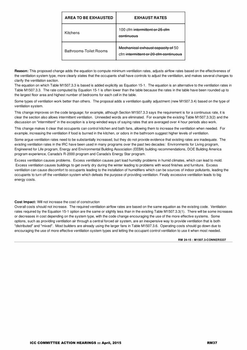
M1507.4M1507.3.6 Local exhaust rates. Local exhaust systems shall be designed to have the capacity to exhaustthe minimum air flow rate determined in accordance with Table M1507.4M1507.3.6. Fans required by this section shallbe provided with controls that enable manual override, such as an on and off switch. Fan controls shall be providedwith ready access from the room served by the fan.
TABLE M1507.4 TABLE M1507.3.6MINIMUM REQUIRED LOCAL EXHAUST RATES FOR ONE- AND TWO-FAMILY DWELLINGS
ICC COMMITTEE ACTION HEARINGS ::: April, 2015 RM36
RM 24-15 : M1507.3-CONNER5337
AREA TO BE EXHAUSTED EXHAUST RATES
Kitchens100 cfm intermittent or 25 cfm
continuous
Bathrooms-Toilet RoomsMechanical exhaust capacity of 50
cfm intermittent or 20 cfm continuous
Reason: This proposed change adds the equation to compute minimum ventilation rates, adjusts airflow rates based on the effectiveness ofthe ventilation system type, more clearly states that the occupants shall have controls to adjust the ventilation, and makes several changes toclarify the ventilation section.The equation on which Table M1507.3.3 is based is added explicitly as Equation 15-1. The equation is an alternative to the ventilation rates inTable M1507.3.3. The rate computed by Equation 15-1 is often lower than the table because the rates in the table have been rounded up tothe largest floor area and highest number of bedrooms for each cell in the table.
Some types of ventilation work better than others. The proposal adds a ventilation quality adjustment (new M1507.3.4) based on the type ofventilation system.
This change improves on the code language; for example, although Section M1507.3.3 says the requirement is for a continuous rate, it isclear the section also allows intermittent ventilation. Unneeded words are eliminated. For example the existing Table M1507.3.3(2) and thediscussion on "intermittent" in the exception is a long-winded ways of saying rates that are averaged over 4 hour periods also work.
This change makes it clear that occupants can control kitchen and bath fans, allowing them to increase the ventilation when needed. Forexample, increasing the ventilation if food is burned in the kitchen, or odors in the bathroom suggest higher levels of ventilation.
Some argue ventilation rates need to be substantially increased, but they do not provide evidence that existing rates are inadequate. Theexisting ventilation rates in the IRC have been used in many programs over the past two decades: Environments for Living program,Engineered for Life program, Energy and Environmental Building Association (EEBA) building recommendations, DOE Building Americaprogram experience, Canada's R-2000 program and Canada's Energy Star program.
Excess ventilation causes problems. Excess ventilation causes part load humidity problems in humid climates, which can lead to mold. Excess ventilation causes buildings to get overly dry during the winter leading to problems with wood finishes and furniture. Excessventilation can cause discomfort to occupants leading to the installation of humidifiers which can be sources of indoor pollutants, leading theoccupants to turn off the ventilation system which defeats the purpose of providing ventilation. Finally excessive ventilation leads to bigenergy costs.
Cost Impact: Will not increase the cost of constructionOverall costs should not increase. The required ventilation airflow rates are based on the same equation as the existing code. Ventilationrates required by the Equation 15-1 option are the same or slightly less than in the existing Table M1507.3.3(1). There will be some increasesor decreases in cost depending on the system type, with the code change encouraging the use of the more effective systems. Someoptions, such as providing ventilation air through a central forced air system, are an inexpensive way to provide ventilation that is both"distributed" and "mixed". Most builders are already using the larger fans in Table M1507.3.6. Operating costs should go down due toencouraging the use of more effective ventilation system types and letting the occupant control ventilation to use it when most needed.
ICC COMMITTEE ACTION HEARINGS ::: April, 2015 RM37

RM 25-15 : M1507.3.2-MOORE4894
RM 25-15M1507.3.2
Proponent: Mike Moore, Newport Ventures, representing Broan-NuTone, representing Newport([email protected])
2015 International Residential CodeRevise as follows:
M1507.3.2 System controls. The whole-house mechanical ventilation system shall be provided with controls thatenable manual override. Such controls shall be provided with text or a symbol that indicates the control's function.
Reason: Tight homes are being outfitted with code-mandated whole-house mechanical ventilation systems. These systems are often simply abathroom exhaust fan expected to run continuously. The problem is that without a label indicating the system's function, homeowners have noidea of the purpose of these systems and are likely to turn them off – thereby increasing the rate of accumulation of harmful indoor pollutantswithout their knowledge. At a minimum, these systems should be labeled to indicate that they are different than a typical bath fan.
Cost Impact: Will increase the cost of constructionThis proposal is expected to have minimal cost impacts, as it simply involves labeling equipment for its intended purpose. This label couldeither be supplied from manufacturers (incremental cost would probably be <$0.10) or field-applied.
ICC COMMITTEE ACTION HEARINGS ::: April, 2015 RM38

RM 26-15M1507.3.3, Chapter 44
Proponent: Robby Schwarz, EnergyLogic, Inc., representing EnergyLogic, Inc. ([email protected])
2015 International Residential CodeRevise as follows:
M1507.3.3 Mechanical ventilation rate. The whole-house mechanical ventilation system shall provide outdoor air ata continuous rate of not less than that as determined in accordance with Table M1507.3.3(1) or in accordance withEquation 15-1.
Equation 15-1Ventilation rate =(0.01 CFM x total square foot area of house) + [(number of bedrooms +1) x 7.5 CFM]
Exception: The whole-house mechanical ventilation system is permitted to operate intermittently where thesystem has controls that enable operation for not less than 25-percent of each 4-hour segment and theventilation rate prescribed in Table M1507.3.3(1) is multiplied by the factor determined in accordance withTable M1507.3.3(2).
Add new standard(s) as follows: ASHRAE 62.2 - 2010 Ventilation and Acceptable Indoor Air Quaility in Low-Rise Residential Buildings
Reason: Many Builders and Designers would like to be more precise in the specification of the air that is utilized to ventilate a home. The tableis good to ensure that ventilation is occurring in a home and for a quick guide for the quantity of air that is needed for whole house mechanicalventilation, but the formula is more precise especially for homes that are on the small side in the floor area chart.
ICC COMMITTEE ACTION HEARINGS ::: April, 2015 RM39

M1507.3.3 Mechanical ventilation rate. The whole house mechanical ventilation system shall provide outdoor air at a continuous rate of notless than thatas determined in accordance with Table M1507.3.3(1) or the ASHRAE 62.2 formula (0.01 CFM x total sqft of house) + ((numberof bedrooms +1) x 7.5CFM) .
Rational Statement:
Many Builders and Designers would like to be more precise in the specification of the air that is utilized to ventilate a home. The table is goodto ensure that ventilation is occurring in a home and for a quick guide for the quantity of air that is needed for whole house mechanicalventilation, but the formula is more precise especially for homes that are on the small side in the floor area chart.
ICC COMMITTEE ACTION HEARINGS ::: April, 2015 RM40

RM 26-15 : M1507.3.3-SCHWARZ4944
Cost Impact: Will not increase the cost of constructionNo cost increase. Possible cost reductions by using more accurate ventilation requirements
Analysis: A review of the standard proposed for inclusion in the code, ASHRAE 62.2, with regard to the ICC criteria for referencedstandards (Section 3.6 of CP#28) will be posted on the ICC website on or before April 2, 2015.
ICC COMMITTEE ACTION HEARINGS ::: April, 2015 RM41

RM 27-15 : M1507.4 (New)-CONNER5309
RM 27-15M1507.4 (New)
Proponent: Craig Conner, representing self ([email protected]); Craig Drumheller([email protected]); Shaunna Mozingo ([email protected])
2015 International Residential CodeAdd new text as follows:
M1507.4 Venting and depressurization. Each fuel-fired furnace, boiler and water heater shall comply one or more ofthe following:
1. It shall be a direct-vent, fan-assisted or power-vented type.2. Where of the natural draft type, it shall be located in a dwelling unit that has only supply or balancedventilation systems.3. It shall be located outside of the dwelling unit's air barrier.4. It shall be located in a mechanical room and provided with combustion air that is supplied entirely from ductsto the outdoors or from direct openings to the outdoors.
Exceptions:
1. This section shall not apply to dwelling units having a tested air tightness of greater than 3 ACH50.2. This section shall not apply to dwelling units having depressurization test results that are within the limitsspecified by an approved depressurization standard.
Reason: This proposal provides clear and practical requirements which limit the types of whole house mechanical ventilation systems whichcan be installed with naturally vented appliances in order to minimize the potential for back drafting. This proposal addresses the most likelyscenarios where back drafting could occur and allows the whole house mechanical ventilation to assist in preventing back drafting rather thanbecoming a contributing factor. The requirements are consistent with Table RA301.1(1) in informative Appendix RA in the 2015 IECC whererecommended depressurization limits in houses are defined. All configurations in the table with depressurization limits less than -5 Pa will nolonger be able to use exhaust only whole house ventilation.
Bibliography: (1) Russell, Marion, Max Sherman and Armin Rudd (2005). "Review of Residential Ventilation Technologies." LBNL Report57730, Ernest Orlando Lawrence Berkeley National Laboratory, Berkeley. California. http://www.buildingscience.com/documents/guides-and-manuals/gm-review-residential-ventilation-technologies
Cost Impact: Will increase the cost of constructionThis code change proposal will increase the cost of construction for certain construction configurations. In a house with a naturally ventedcombustion appliances where exhaust-only ventilation was the preferred method of whole house ventilation, there will be an increase in costto change to a supply type system. According to a 2005 study(1) the additional cost to go from a single-point exhaust system to a central-fanintegrated supply system (without exhaust) will be roughly $155.
ICC COMMITTEE ACTION HEARINGS ::: April, 2015 RM42

RM 28-15 : M1507.4-FLOYD3605
RM 28-15M1507.4
Proponent: Anthony Floyd, City of Scottsdale, representing City of Scottsdale([email protected])
2015 International Residential CodeRevise as follows:
M1507.4 Local exhaust ratessystem. Local exhaust systems shall be designed to have the capacity to exhaust theminimum air flow rate determined in accordance with Table M1507.4. Except where functioning as a component of awhole house ventilation system, exhaust fans shall be controlled by a humidity control. Humidity controls shall becapable of adjustment between a relative humidity range of 50 to 80 percent. A humidity control shall utilize manual orautomatic means of adjustment and shall be a separate component or an integral component of the exhaust fan.
Reason: Bathroom exhaust fans are often underutilized by occupants. Properly operated exhaust fans removes moisture and odors therebyimproving the functionality of the space and contributing to a healthy and sanitary environment. Unless functioning as a component of a wholehouse ventilation system, effective moisture and odor removal is achieved by humidity sensor controls. Humidity controls ensure the exhaustsystem operates when the bathroom is in use and for a period of time after the occupant has left the room.During a bath or shower, the humidity level in a bathroom can be a perfect breeding ground for mold, mildew and microorganisms that canimpact your health. Excess moisture has tremendous potential for damaging a home. It cracks and peels paint, ruins gypsum wallboard,causes exterior paint failure, warps doors and rusts cabinets and fixtures. Without control, it can even cause deterioration of joists andframing. As it condenses on windows, walls, ceilings and cabinets, it attracts dirt. It encourages mildew on tile grout and generally provides anenvironment for increased bacterial growth.
Depending on the size of the bathroom, an intermittent exhaust fan needs to run at least 20 minutes after each shower to ensure thatmoisture levels are reduced. Both intermittent and continuous bathroom exhaust systems reduce the risk of mold growth which is a significanthealth concern in homes. Moisture sensor controlled exhaust fans are far more effective than a timed or manually operated fan or anoperable window that is usually left closed during the winter and summer months of the year.
Bibliography: Home Ventilating Institute - http://www.hvi.org/publications/HowMuchVent.cfmGreenCodePro/CALGreen - http://greencodepro.com/code-summaries/california-green-building-standards-code/4-506-1-bathroom-exhaust-fans
LEED for Homes Reference Guide, 2008. p. 301-302.
Cost Impact: Will increase the cost of constructionExhaust fan costs range from $106 for an 80 cfm with humidity sensor control to $251 for an 80 cfm with humidity sensor control, motionsensor, and quiet sound rating. The minimum cost for a roof vent kit with flex duct is $23. Moisture controlled bathroom exhaust fansminimizes the potential for building damage, saving the cost of making repairs to correct problems that could have been easily avoided.
ICC COMMITTEE ACTION HEARINGS ::: April, 2015 RM43

RM 29-15 : M1601.1.1-BALLANCO3972
RM 29-15M1601.1.1
Proponent: Julius Ballanco, JB Engineering and Code Consulting, P.C., representing Self([email protected])
2015 International Residential CodeRevise as follows:
M1601.1.1 Above-ground duct systems. Above-ground duct systems shall conform to the following:
1. Equipment connected to duct systems shall be designed to limit discharge air temperature to not greaterthan 250°F (121°C).
2. Factory-madeListed factory-made ducts shall be listed and labeled in accordancecomply with UL 181 andinstalled in accordance with the manufacturer's instructions.
3. Fibrous glass duct construction shall conform to the SMACNA Fibrous Glass Duct ConstructionStandards or NAIMA Fibrous Glass Duct Construction Standards.
4. Field-fabricated and shop-fabricated metal and flexible duct constructions shall conform to the SMACNAHVAC Duct Construction Standards—Metal and Flexible except as allowed by Table M1601.1.1.Galvanized steel shall conform to ASTM A 653.
5. The use of gypsum products to construct return air ducts or plenums is permitted, provided that the airtemperature does not exceed 125°F (52°C) and exposed surfaces are not subject to condensation.
6. Duct systems shall be constructed of materials having a flame spread index of not greater than 200.7. Stud wall cavities and the spaces between solid floor joists to be used as air plenums shall comply with
the following conditions:7.1. These cavities or spaces shall not be used as a plenum for supply air.
8. These cavities or spaces shall not be part of a required fire-resistance-rated assembly.9. Stud wall cavities shall not convey air from more than one floor level.10. Stud wall cavities and joist-space plenums shall be isolated from adjacent concealed spaces by tight-
fitting fireblocking in accordance with Section R602.8.11. Stud wall cavities in the outside walls of building envelope assemblies shall not be utilized as air plenums.
Reason: As currently written, Item 2 mandated UL 181. However, many sheet metal manufacturers make duct in their shop. A contractorsshop would in essence qualify as a factory. However, contractors do not have listing and labeling of their duct. This section is also in conflictwith other items, spectifically Item 3, 4, and 6. This section should simply allow the use of UL 181 duct as opposed to appearing to requirecompliance.
Cost Impact: Will not increase the cost of constructionThis will lower the cost of construction by allowing any viable duct to be used in a dwelling unit.
ICC COMMITTEE ACTION HEARINGS ::: April, 2015 RM44

RM 30-15 : M1601.1.1-BALLANCO5109
RM 30-15M1601.1.1
Proponent: Julius Ballanco, JB Engineering and Code Consulting, P.C., representing General Plastics([email protected])
2015 International Residential CodeRevise as follows:
M1601.1.1 Above-ground duct systems. Above-ground duct systems shall conform to the following:
1. Equipment connected to duct systems shall be designed to limit discharge air temperature to not greaterthan 250°F (121°C).
2. Factory-made ducts shall be listed and labeled in accordance with UL 181 and installed in accordance withthe manufacturer's instructions.
3. Fibrous glass duct construction shall conform to the SMACNA Fibrous Glass Duct ConstructionStandards or NAIMA Fibrous Glass Duct Construction Standards.
4. Field-fabricated and shop-fabricated metal and flexible duct constructions shall conform to the SMACNAHVAC Duct Construction Standards—Metal and Flexible except as allowed by Table M1601.1.1.Galvanized steel shall conform to ASTM A 653.
5. The use of gypsum products to construct return air ducts or plenums is permitted, provided that the airtemperature does not exceed 125°F (52°C) and exposed surfaces are not subject to condensation.
6. Duct systems shall be constructed of materials having a flame spread index of not greater than 200.7. Stud wall cavities and the spaces between solid floor joists to be used as air plenums shall comply with
the following conditions:7.1. These cavities or spaces shall not be used as a plenum for supply air.7.2. These cavities or spaces shall not be part of a required fire-resistance-rated assembly.7.3. Stud wall cavities shall not convey air from more than one floor level.7.4. Stud wall cavities and joist-space plenums shall be isolated from adjacent concealed spaces
by tight-fitting fireblocking in accordance with Section R602.8.7.5. Stud wall cavities in the outside walls of building envelope assemblies shall not be utilized as
air plenums.8. PVC plastic duct and fitting material shall conform to cell classification 12454-B of ASTM D1248 or ASTM
D1784 and the external loading properties of ASTM D2412. The duct temperature for plastic ducts shallnot exceed 150° F (66° C).
Reason: The PMGCAC raised a concern last cycle regarding the requirements for plastic duct above ground. The plastic duct being usedabove ground is the same duct that is used for underground installations. This change will add the plastic duct requirements to the list ofabove ground duct systems using the language in Section M1601.1.2 to regulate the material requirement.Item 6 in this section was originally added to the code during the initial hearings for the IRC when I proposed the inclusion of plastic ductsabove ground. The Committee, at that time, thought the text would be more clear by referencing a flame spread of 200 rather than thelanguage proposed for plastic duct. As such, plastic ducts have always been permitted by the IRC for above ground installations. This willsimply add more specific requirements for the duct material.
Cost Impact: Will not increase the cost of constructionThis change clarifies the requirement for PVC plastic duct and fittings. These are optional materials that may be used for duct construction.
ICC COMMITTEE ACTION HEARINGS ::: April, 2015 RM45

RM 31-15 : M1601.1.1-MCMANN3699
RM 31-15M1601.1.1
Proponent: Guy McMann, Jefferson County Colorado, representing Colorado Associatoin of Plumbingand Mechanical Officials (CAPMO) ([email protected])
2015 International Residential CodeRevise as follows:
M1601.1.1 Above-ground duct systems. Above-ground duct systems shall conform to the following:
1. Equipment connected to duct systems shall be designed to limit discharge air temperature to not greaterthan 250°F (121°C).
2. Factory-made ducts shall be listed and labeled in accordance with UL 181 and installed in accordance withthe manufacturer's instructions.
3. Fibrous glass duct construction shall conform to the SMACNA Fibrous Glass Duct ConstructionStandards or NAIMA Fibrous Glass Duct Construction Standards.
4. Field-fabricated and shop-fabricated metal and flexible duct constructions shall conform to the SMACNAHVAC Duct Construction Standards—Metal and Flexible except as allowed by Table M1601.1.1.Galvanized steel shall conform to ASTM A 653.
5. The use of gypsum products to construct return air ducts or plenums is permitted, provided that the airtemperature does not exceed 125°F (52°C) and exposed surfaces are not subject to condensation.
6. Duct systems shall be constructed of materials having a flame spread index of not greater than 200.7. Stud wall cavities and the spaces between solid floor joists to be used as air plenums shall comply with
the following conditions:7.1. These cavities or spaces shall not be used as a plenum for supply air.7.2. These cavities or spaces shall not be part of a required fire-resistance-rated assembly.7.3. Stud wall cavities shall not convey air from more than one floor level.7.4. Stud wall cavities and joist-space plenums shall be isolated from adjacent concealed spaces
by tight-fitting fireblocking in accordance with Section R602.8.7.5. Stud wall cavities in the outside walls of building envelope assemblies shall not be utilized as
air plenums8. Volume dampers, equipment and other means of supply, return and exhaust air adjustment used in
system balancing shall be provided with access.
Reason: This language is absent in the IRC and is critical that access be provided for these devices in order to properly balance a system..
Cost Impact: Will increase the cost of constructionIt is possible that an increase in cost might occur if access doors need to be purchased. Otherwise not.
ICC COMMITTEE ACTION HEARINGS ::: April, 2015 RM46

RM 32-15 : M1601.1.1-SCHWARZ4948
RM 32-15M1601.1.1
Proponent: Robby Schwarz, representing EnergyLogic, Inc. ([email protected])
2015 International Residential CodeRevise as follows:
M1601.1.1 Above-ground duct systems. Above-ground duct systems shall conform to the following:
1. Equipment connected to duct systems shall be designed to limit discharge air temperature to not greaterthan 250°F (121°C).
2. Factory-made ducts shall be listed and labeled in accordance with UL 181 and installed in accordance withthe manufacturer's instructions.
3. Fibrous glass duct construction shall conform to the SMACNA Fibrous Glass Duct ConstructionStandards or NAIMA Fibrous Glass Duct Construction Standards.
4. Field-fabricated and shop-fabricated metal and flexible duct constructions shall conform to the SMACNAHVAC Duct Construction Standards—Metal and Flexible except as allowed by Table M1601.1.1.Galvanized steel shall conform to ASTM A 653.
5. The use of gypsum products to construct return air ducts or plenums is permitted, provided that the airtemperature does not exceed 125°F (52°C) and exposed surfaces are not subject to condensation.
5. Duct systems shall be constructed of materials having a flame spread index of not greater than 200.6. Stud wall cavities and the spaces between solid floor joists to be used as air plenums shall comply with
the following conditions:6.1. These cavities or spaces shall not be used as a plenum for supply or return air.6.2. These cavities or spaces shall not be part of a required fire-resistance-rated assembly.6.3. Stud wall cavities shall not convey air from more than one floor level.6.4. Stud wall cavities and joist-space plenums shall be isolated from adjacent concealed spaces
by tight-fitting fireblocking in accordance with Section R602.8.6.5. Stud wall cavities in the outside walls of building envelope assemblies and the spaces
between solid floor joists in any portion of the building shall not be utilized as supply or returnair plenums.
Reason: Rational Statement:Air is a fluid like water is a fluid. Code will not stand for a plumbing system that leaks but allows a minimum level of duct leakage even thoughthe air that is carried through the duct system carries heat, moisture, and pollutants that can be detrimental to the building occupant and thestructure. Many have read the language in the last two cycles of the code to mean that both the supply side and the return side of an HVACsystem need to be fully ducted. However the commentary has left a window of opportunity for contractors to continue to utilize buildingcavities for return air plenums. To be crystal clear, this code change proposal is largely in response to that and is designed to ensure that allHVAC duct systems are fully ducted to ensure life safety, long term durability, cost effectiveness, comfort and efficiency as they are allimpacted by air under pressure being forced through un-ducted building cavities. A number of papers have been written about the decreasein efficiency and comfort as well as the increase in building durability issues and cost of ownership associated with air traveling through andout of un-ducted building cavities. Much of this air also is pulled into and out of the building due to the connection of the cavity to the outside.Negative pressure are a significant issue for combustion safety is a home and are more likely to impact atmospherically vented appliancesthrough the leakage associated with building cavities used as returns. For all of these reasons and more all air pushed our pulled by an HVACblower motor should be contained inside a duct system.
Cost Impact: Will increase the cost of constructionCost implications are small with this proposal as building cavities need to be enclosed any way so air can flow through them. However thisproposal is requiring that return air be enclosed in duct work and there will be a cost associated with that. However, this requirement, as welland the enhanced duct sealing requirements of the IECC, leads builders to the utilization of centralized returns which diminishes the amount ofreturn duct work in the house drastically, maintains comfort and performance of the HVAC system, and is very cost affective.
ICC COMMITTEE ACTION HEARINGS ::: April, 2015 RM47

RM 33-15M1601.1.1
Proponent: Donald Surrena, National Association of Home Bulilders, representing National Associationof Home Builders ([email protected]); Jay Peters, representing AQC Industries ([email protected])
2015 International Residential CodeRevise as follows:
M1601.1.1 Above-ground duct systems. Above-ground duct systems shall conform to the following:
1. Equipment connected to duct systems shall be designed to limit discharge air temperature to not greaterthan 250°F (121°C).
2. Factory-made ducts shall be listed and labeled in accordance with UL 181 and installed in accordance withthe manufacturer's instructions.
3. Fibrous glass duct construction shall conform to the SMACNA Fibrous Glass Duct ConstructionStandards or NAIMA Fibrous Glass Duct Construction Standards.
4. Field-fabricated and shop-fabricated metal and flexible duct constructions shall conform to the SMACNAHVAC Duct Construction Standards—Metal and Flexible except as allowed by Table M1601.1.1.Galvanized steel shall conform to ASTM A 653.
5. The use of gypsum products to construct return air ducts or plenums is permitted, provided that the airtemperature does not exceed 125°F (52°C) and exposed surfaces are not subject to condensation.
6. PolyethyleneDuct duct systems shall be constructed of materials having a flame spread index of notgreater than 200.
7. Stud wall cavities and the spaces between solid floor joists to be used as air plenums shall comply withthe following conditions:
7.1. These cavities or spaces shall not be used as a plenum for supply air.7.2. These cavities or spaces shall not be part of a required fire-resistance-rated assembly.7.3. Stud wall cavities shall not convey air from more than one floor level.7.4. Stud wall cavities and joist-space plenums shall be isolated from adjacent concealed spaces
by tight-fitting fireblocking in accordance with Section R602.8.7.5. Stud wall cavities in the outside walls of building envelope assemblies shall not be utilized as
air plenums.8. PVC and CPVC ducts and fittings not covered by external duct insulation shall be constructed ofmaterial having a flame spread index not greater than 25 and a smoke development index not greater than50 when tested in accordance with ASTM E 84 or UL 723. PVC and CPVC ducts and fittings shall beconstructed of material having a flame spread index not greater than 25 and a smoke development indexnot greater than 500 when tested in accordance with ASTM E 84 or UL 723 where such ducts and fittingsare covered by external duct insulation material conforming to Section M1601.3. The design airtemperature within PVC and CPVC duct systems shall not exceed 140°F (60°C).
Reason: There is a need to more clearly support the use of above-ground plastic ducts in the International Residential Code (IRC) SectionM1601.1.1. Plastic ducts appear to be "technically" allowed under this IRC Section but often receive rejection at the local jurisdiction level dueto lack of specificity, clarity, and coherence, particularly in regards to the language of IRC Section M1601.21 and the International MechanicalCode (IMC) Section 603.8.32. Unclear and incomplete duct material requirements make using lower-cost, higher-performing duct systemsunnecessarily difficult or impossible depending on interpretation at the local jurisdiction level.Solvent welded assembly of plastic ducts inherently results in low air leakage and low airflow resistance. These relatively lower-cost materialsare commonly available in appropriate small sizes for space conditioning airflow in low-load houses.
After researching the history, it was found that item 6 under Section M1601.1.1 was established specifically to allow polyethylene ducts,fittings and transitions (often blow-molded) to be used in above-ground duct systems. Based on feedback from industry stakeholders, buildingofficials and ICC staff, the lack of clarity in this section regarding the intended material has been an ongoing problem. Calling out the intendedpolyethylene material will make this section clear and enforceable, clarifying that not only polyethylene fitings are allowed, but the duct systemconstructed of the same material.
Some available CPVC products made with fire retardant already meet the 25/50 flame spread and smoke development limitation, without beingwater filled. While the ignition temperature of PVC is up to 850°F (455°C), PVC and CPVC are self-extinguishing materials, meaning that theywill stop burning when the heat source is removed. Typical PVC has a flame spread index in the range of 15, far less than the Class 1 ductlimit of 25. The smoke development index for PVC is in the range of 500, but testing of available duct wrap products has been shown toreduce the smoke development index to less than 50.
In prior proposals related to this Section, questions have been raised about PVC brittleness and PVC off-gassing. Regarding PVC brittleness:
ICC COMMITTEE ACTION HEARINGS ::: April, 2015 RM48

RM 33-15 : M1601.1.1-SURRENA5025
PVC becomes brittle in extreme cold, but if it were installed as an air duct in an extreme cold location it would be insulated, protectingit from cold and potentially damaging impact.PVC will soften and lose strength with excessive heat, but that condition is well above the 140°F design air temperature limitationimposed in this proposal. (As a further note about the 140°F limit, that is not a technical limit to be confused with the 150°F limit givenfor plastic ducts in Section M1601.1.2, rather, 140°F is a reasonable practical limit since there is no practical need to supply heatedair in dwellings above 140°F in dwellings. Modern condensing furnaces typically deliver heated air in the range of 110°F to 115°F.Air delivered much hotter than that can cause comfort and air distribution/stratification problems, as remembered by the old"scorched air" complaints.)PVC will break down and get brittle if left exposed to UV light, but once again it would be covered with insulation and protected in thatcase.PVC will degrade with age as plasticizers added in manufacturing are lost. After an estimated 50 years, its effective pressurecapability may drop but not in the range of air duct pressures. In addition, PVC is already approved for use with pressurized water.
Regarding VOC off-gassing, the chart below obtained from http://www.madisongroup.com/case-studies-pvc-pipe.html shows test resultsfrom a thermogravimetric analyzer (TGA) where the PVC sample was gradually heated. Decomposition of different compounds can be seenalong with the percent weight loss. The decomposition peaks can be matched with known materials that decompose at the same exacttemperature. Referring to the curve marked (1), there was no recorded weigh loss until about 150°C (302°F ).
————————————
1 IRC Chapter 16 Duct Systems, Section 1601.2 states that, "Each portion of a factory-made air duct shall bear a listing and label indicatingcompliance with UL 181 and UL 181A or UL 181B."2 IMC Chapter 6 Duct Systems, Section 603.8.3 states that, "Plastic duct and fittings shall be utilized in underground installations only."
Cost Impact: Will not increase the cost of constructionSince the added text clarifies that PVC, CPVC and polyethylene may be used–as an option–in duct construction, there is no added costassociated with this proposal. In fact, it may reduce construction costs by allowing contractors more options. Where PVC or CPVC ducts arerequired to have an external insulation covering material conforming to Section M1601.3, the comparison would only be where the ducts areinside conditioned space which is the only case where they can be uninsulated. Flexible duct and fibrous duct board are pre-insulated factoryducts. Therefore, the cost comparison is only between uninsulated metal ducts and insulated plastic ducts. In that case, it is estimated thatthe cost of minimally insulated plastic duct is roughly equivalent to the cost of uninsulated metal duct.
ICC COMMITTEE ACTION HEARINGS ::: April, 2015 RM49

RM 34-15 : M1601.1.2-PETERS5253
RM 34-15M1601.1.2
Proponent: Jay Peters, Codes and Standards International, representing AQC Industries([email protected])
2015 International Residential CodeRevise as follows:
M1601.1.2 Underground duct systems. Underground duct systems shall be constructed of approved concrete, clay,metal or plastic. The maximum ductdesign temperature for systems utilizing plastic ductsduct and fittings shall not begreater than 150°F (66°C). Metal ducts shall be protected from corrosion in an approved manner or shall becompletely encased in concrete not less than 2 inches (51 mm) thick. Nonmetallic ducts shall be installed inaccordance with the manufacturer's instructions. Plastic pipe and fitting materials shall conform to cell classification12454-B of ASTM D 1248 or ASTM D 1784 and external loading properties of ASTM D 2412. Ducts shall slope to anaccessible point for drainage. Where encased in concrete, ductsDucts shall be sealed, secured and securedtestedwith air at a pressure of not less than 2 inches of W.C. for not less than 5 minutes in the presence of the code officialprior to anyencasing the ducts in concrete being pouredor direct burial. Metallic ducts having an approved protectivecoating and nonmetallic ducts shall be installed in accordance with the manufacturer's instructions.
Reason: This air temperature language does not change the substantive technical content of the provision but uses the exact samelanguage as the IMC to bring uniformity to the codes.All duct leakage, whether in the envelope, in the attic, or underground is undesireable but underground ducts are more likely to cause seriousissues due to their location. Underground ducts systems have a propensity to leak which causes air exfiltration (loss) and also duct infiltration(gain) of contaminants into the duct system and residence. The leakage, in-and-out, not only causes poor indoor air quality, duct systemdegradation, sick building occupants, mold, mildew and even radon contamination, but also wastes energy. Some estimate that after thecombined infiltration from walls/ceilings/floors, the duct system is the next largest cause of air leakage in the residence. Underground returnair ducts are of particular concern due to the negative pressure within the duct system, causing intake of impurities. All ducts are to be sealedbefore burial, whether in concrete or directly buried in the ground but the code does not require any verification or test to prove the system isairtight, or more importantly, watertight. Metallic ducts encased in concrete, as well as those approved for direct burial should be tested to findleaks before burial, not afterwards, or never at all.
Cost Impact: Will increase the cost of constructionAlthough I have checked the box for additional cost, underground duct systems, when installed by quality contractors and installed correctlyshould already be performing this test. The proposal for air test may add a minimal cost to initial installation but has potential to save money inthe long run through greater energy savings, indoor air quality and future repairs.
ICC COMMITTEE ACTION HEARINGS ::: April, 2015 RM50

RM 35-15M1601.1.3 (New), M1601.1.3.1 (New), M1601.1.3.2 (New), M1601.1.3.3 (New), M1601.1.3.4(New), M1601.1.3.5 (New), M1601.1.3.6 (New), M1601.1.3.7 (New), M1601.1.3.8 (New),M1601.4.1, M1601.4.3.1 (New), Chapter 44
Proponent: Ralph Koerber, ATCO Rubber Products, Inc., representing Air Diffusion Council (ADC)([email protected])
2015 International Residential CodeAdd new text as follows:
M1601.1.3 Nonmetallic Ducts Nonmetallic ducts shall be constructed with Class 0 or Class 1 duct material and shallcomply with UL181. Fibrous duct construction shall conform to the SMACNA Fibrous Glass Duct ConstructionStandards or NAIMA Fibrous Glass Duct Construction Standards. Flexible air ducts and air connectors shall complywith the ADC Flexible Duct Performance & Installation Standards. The air temperature within nonmetallic ducts shallnot exceed 250ºF (121ºC).
M1601.1.3.1 Flexible Air Ducts and Air Connectors Flexible air ducts, both metallic and non-metallic, shall complywith Sections M1601.1.3.2, M1601.1.3.3, M1601.1.2.7, and M1601.1.3.8. Flexible air connectors, both metallic andnonmetallic, shall comply with Sections M1601.1.3.4 through M1601.1.3.8.
M1601.1.3.2 Flexible air ducts Flexible air ducts, both metallic and nonmetallic, shall be tested in accordance withUL181. Such ducts shall be listed and labeled as Class 0 or Class 1 flexible air ducts and shall be installed inaccordance with their listing.
M1601.1.3.3 Duct length. Flexible air ducts shall not be limited in length. Flexible air ducts shall be installed fullyextended. The provision of excess duct length for the purpose of possible future relocation of air terminal devices isprohibited.
M1601.1.3.4 Flexible air connectors Flexible air connectors, both metallic and nonmetallic, shall be tested inaccordance with UL181. Such connectors shall be listed and labeled as Class 0 or Class 1 flexible air connectors andshall be installed in accordance with their listing.
M1601.1.3.5 Connector length. Flexible air connectors shall be limited in length to 14 feet (4267 mm). .Flexible air connectors and multiple lengths of flexible air connector that have been joined together shall be limited inlength to 14 feet (4267 mm). Flexible air connectors shall be installed fully extended. .
M1601.1.3.6 Connector penetration limitations. Flexible air connectors shall not pass through any wall, floor, orceiling.
M1601.1.3.7 Flexible air duct and air connector clearance. Flexible air ducts and air connectors shall be installedwith clearances to appliances as specified in the appliance manufacturer's installation instructions.
M1601.1.3.8 Flexible air duct and air connector bends. Where flexible air ducts and air connectors are used inplace of metallic elbows, the bend radius shall be greater than or equal to one (1) duct diameter measured to the outersurface of the duct on the inside of the bend.
Revise as follows:
M1601.4.1 Joints, seams and connections. Longitudinal and transverse joints, seams and connections in metallicand nonmetallic ducts shall be constructed as specified in SMACNA HVAC Duct Construction Standards—Metal andFlexible and NAIMA Fibrous Glass Duct Construction Standards. Joints, longitudinal and transverse seams, andconnections in ductwork shall be securely fastened and sealed with welds, gaskets, mastics (adhesives), mastic-plus-embedded-fabric systems, liquid sealants or tapes. Tapes and mastics used to seal fibrous glass ductwork shallbe listed and labeled in accordance with UL 181A and shall be marked "181A-P" for pressure-sensitive tape, "181 A-M" for mastic or "181 A-H" for heat-sensitive tape.
Tapes and mastics used to seal metallic and flexible air ducts and flexible air connectors shall comply with UL181B and shall be marked "181 B-FX" for pressure-sensitive tape or "181 BM" for mastic.
Duct connections to flanges of air distribution system equipment shall be sealed and mechanically fastened.Mechanical fasteners for use with flexible nonmetallic air ducts shall comply with UL 181B and shall be marked 181B-
ICC COMMITTEE ACTION HEARINGS ::: April, 2015 RM51

RM 35-15 : M1601.1.3 (New)-KOERBER5138
C. Crimp joints for round metallic ducts shall have a contact lap of not less than 1 inch (25 mm) and shall bemechanically fastened by means of not less than three sheet-metal screws or rivets equally spaced around the joint.
Tapes and mastics used to seal metallic and nonmetallic flexible air ducts and flexible air connectors shall complywith UL 181B and shall be marked "181 B-FX" for pressure-sensitive tape or "181 BM" for mastic. Fittings used incombination with flexible air ducts and air connectors shall have a flange length of not less than 2 inches (51 mm) forconnection of the flexible duct. Flexible duct inner cores shall be installed not less than 1" (25mm) onto the fitting priorto taping and application of the mechanical fastener. Mastic shall be applied in accordance with the masticmanufacturer's installation instructions prior to pulling the inner core onto the fitting and applying the mechanicalfastener. Nonmetallic mechanical fasteners for use with flexible nonmetallic air ducts shall comply with UL 181B andshall be marked 181B-C. Where nonmetallic mechanical fasteners are used, the fittings shall be beaded. Theinsulation and outer vapor barrier of flexible ducts shall be sealed to the fitting using 2 wraps of approved duct tape ora mechanical fastener in place of, or in conjunction with, the tape.
Closure systems used to seal all ductwork shall be installed in accordance with the manufacturers' instructions.
Exceptions:1. Spray polyurethane foam shall be permitted to be applied without additional joint seals.2. Where a duct connection is made that is partially inaccessible, three screws or rivets shall be
equally spaced on the exposed portion of the joint so as to prevent a hinge effect.3. For ducts having a static pressure classification of less than 2 inches of water column (500 Pa),
additional closure systems shall not be required for continuously welded joints and seams andlocking-type joints and seams of other than the snap-lock and button-lock types.
Add new text as follows:
M1601.4.3.1 Support Flexible air ducts and air connectors shall be supported at intervals not to exceed 4 feet(1219mm) where installed horizontally and 6 feet (1829mm) where installed as vertical risers and shall be installed inaccordance with the manufacturer's installation instructions and the ADC Flexible Duct Performance & InstallationStandards. Supports shall be not less than 1.5 inches (38mm) in width and the sag between supports shall not exceed1/2" (13mm) per foot of duct length between supports.
Add new standard(s) as follows: Air Diffusion Council
1901 N. Roselle Road, Suite 800
Schaumburg, IL 60195
ADC Flexible Duct Performance & Installation Standards, 5th Edition
Reason: The proposed revised and added text is companion to similar proposals made to the IMC Chapter 6.The changes and revisions included seek to clarify important aspects of proper flexible duct installation.
All of the language, to my knowledge, is currently included either within the manufacturer's installation instructions supplied with flexible ductsthat are listed and labeled to the UL181 Standard, the UL181B Standard for Closure Systems, and within the Air Diffusion Council FlexibleDuct Performance & Installation Standards.
Although the code language currently requires that products be installed per the listing and per the manufacturer's installation instructions, thisadded or revised text within the code sections should help clarify important aspects of proper flexible duct installations.
Some revisions are only movement of text within the sections to facilitate flow of information and relavence.
Cost Impact: Will not increase the cost of constructionSince the intent of the proposal is to clarify existing requirements (per the manufacturer's installation instructions already required), thereshould be no additional cost impact if these revisions are included.
Analysis: A review of the standard proposed for inclusion in the code, ADC Flexible Duct Performance & Installation Standards, with regard to the ICCcriteria for referenced standards (Section 3.6 of CP#28) will be posted on the ICC website on or before April 2, 2015.
ICC COMMITTEE ACTION HEARINGS ::: April, 2015 RM52
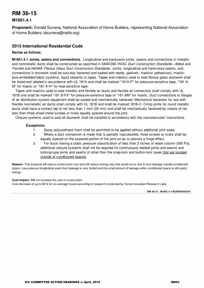
RM 36-15 : M1601.4.1-SURRENA5018
RM 36-15M1601.4.1
Proponent: Donald Surrena, National Association of Home Builders, representing National Associationof Home Builders ([email protected])
2015 International Residential CodeRevise as follows:
M1601.4.1 Joints, seams and connections. Longitudinal and transverse joints, seams and connections in metallicand nonmetallic ducts shall be constructed as specified in SMACNA HVAC Duct Construction Standards—Metal andFlexible and NAIMA Fibrous Glass Duct Construction Standards. Joints, longitudinal and transverse seams, andconnections in ductwork shall be securely fastened and sealed with welds, gaskets, mastics (adhesives), mastic-plus-embedded-fabric systems, liquid sealants or tapes. Tapes and mastics used to seal fibrous glass ductwork shallbe listed and labeled in accordance with UL 181A and shall be marked "181A-P" for pressure-sensitive tape, "181 A-M" for mastic or "181 A-H" for heat-sensitive tape.
Tapes and mastics used to seal metallic and flexible air ducts and flexible air connectors shall comply with UL181B and shall be marked "181 B-FX" for pressure-sensitive tape or "181 BM" for mastic. Duct connections to flangesof air distribution system equipment shall be sealed and mechanically fastened. Mechanical fasteners for use withflexible nonmetallic air ducts shall comply with UL 181B and shall be marked 181B-C. Crimp joints for round metallicducts shall have a contact lap of not less than 1 inch (25 mm) and shall be mechanically fastened by means of notless than three sheet-metal screws or rivets equally spaced around the joint.
Closure systems used to seal all ductwork shall be installed in accordance with the manufacturers' instructions.
Exceptions:1. Spray polyurethane foam shall be permitted to be applied without additional joint seals.2. Where a duct connection is made that is partially inaccessible, three screws or rivets shall be
equally spaced on the exposed portion of the joint so as to prevent a hinge effect.3. For ducts having a static pressure classification of less than 2 inches of water column (500 Pa),
additional closure systems shall not be required for continuously welded joints and seams andlocking-type joints and seams of other than the snap-lock and button-lock types that are locatedoutside of conditioned spaces.
Reason: This proposal will reduce construction cost and still reduce energy loss that would occur due to duct leakage outside conditionedspace. Low pressure longitudinal seam duct leakage is very limited and the small amount of leakage within conditioned space is still usefulenergy.
Cost Impact: Will not increase the cost of constructionCost decrease of up to $314 for an average house according to research conducted by Home Innovation Research Labs.
ICC COMMITTEE ACTION HEARINGS ::: April, 2015 RM53

RM 37-15 : M1602.2-MCMANN3700
RM 37-15M1602.2
Proponent: Guy McMann, Jefferson County Colorado, representing Colorado Association of Plumbingand Mechanical Officials (CAPMO) ([email protected])
2015 International Residential CodeRevise as follows:
M1602.2 Return air openings. Return air openings for heating, ventilation and air conditioning systems shall complywith all of the following:
1. Openings shall not be located less than 10 feet (3048 mm) measured in any direction from an opencombustion chamber or draft hood of another appliance located in the same room or space.
2. The amount of return air taken from any room or space shall be not greater than the flow rate of supply airdelivered to such room or space.
3. Return and transfer openings shall be sized in accordance with the appliance or equipment manufacturers'installation instructions, Manual D or the design of the registered design professional.
4. Return air shall not be taken from a closet, bathroom, toilet room, kitchen, garage, mechanical room,boiler room, furnace room or unconditioned attic.
Exceptions:1. Taking return air from a kitchen is not prohibited where such return air openings serve
the kitchen only, and are located not less than 10 feet (3048 mm) from the cookingappliances.
2. Dedicated forced-air systems serving only the garage shall not be prohibited fromobtaining return air from the garage.
5. Taking return air from an unconditioned crawl space shall not be accomplished through a direct connectionto the return side of a forced-air furnace. Transfer openings in the crawl space enclosure shall not beprohibited.
6. Return air from one dwelling unit shall not be discharged into another dwelling unit.7. Return air shall not be taken from indoor swimming pool enclosures and associated deck areas except
where such space is dehumidified,
Reason: It is not desirable to pull return air from swimming pool areas due to the affects it would have on the system from humidity andchemical odors associated with such spaces. A dedicated system would be required or a combination of supply and exhaust. This scenariois consistent with the same dwelling built under the IMC.
Cost Impact: Will not increase the cost of constructionGenerally speaking this proposal is will not cause an increase is cost. If dehumidificaton is chosen then there could be an increase in cost.
ICC COMMITTEE ACTION HEARINGS ::: April, 2015 RM54

RM 38-15 : M2005.1-MCMANN3692
RM 38-15M2005.1, M2005.2, M2005.2.1
Proponent: Guy McMann, Jefferson County, Colorado, representing Colorado Associatoin of Plumbingand Mechanical Officials (CAPMO) ([email protected])
2015 International Residential CodeRevise as follows:
M2005.1 General. Water heaters shall be installed in accordance with Chapter 28, the manufacturer's instructions andthe requirements of this code. Water heaters installed in an attic shall comply with the requirements of SectionM1305.1.3. Gas-fired water heaters shall comply with the requirements in Chapter 24. Domestic electric waterheaters shall comply with UL 174. Oiled-fired water heaters shall comply with UL 732. Thermal solar water heatersshall comply with Chapter 23 and UL 174. Solid fuel-fired water heaters shall comply with UL 2523.
M2005.2 Prohibited locations. Fuel-fired water heaters shall not be located in sleeping rooms, bathrooms, toiletrooms, storage closets or a space that opens only to such room or spaces.
Exceptions:
1. The water heater is a direct- vent appliance installed in accordance with the terms of its listing and themanufacturer's installation instructions.
2. Where the water heater is installed in a room used as a storage closet. Water heaters located inor spacethat opens only into a bedroom or bathroom, the room or space shall be installed inprovided with a sealedenclosure so that solid weather stripped door equipped with an approved self-closing device. Allcombustion air will not shall be taken directly from the living spaceoutdoors. Installation of direct-ventwater heaters within an enclosure is not required.
M2005.2.1 Water heater access. Access to water heaters that are located in an attic or underfloor crawl space ispermitted toshall be through a closet located in a sleeping room or bathroom where ventilation of those spaces is inaccordance with this code.Section M1305.
Reason: This section lacks some general informatoin and is incomplete. It is also in need of a little cleanup. There are no new requirements.
Cost Impact: Will not increase the cost of constructionThis proposal is strictly editorial in nature and will not cause an increase is cost.
ICC COMMITTEE ACTION HEARINGS ::: April, 2015 RM55

RM 39-15 : M2006.1-HATFIELD5744
RM 39-15M2006.1, M2006.3, Chapter 44
Proponent: Jennifer Hatfield, J. Hatfield & Associates, PL, representing Association of Pool & SpaProfessionals ([email protected])
2015 International Residential CodeRevise as follows:
M2006.1 General. Pool and spa heaters shall be installed in accordance with the manufacturer's installationinstructions. Oil-fired pool heaters shall comply with UL 726. Electric pool and spa heaters shall comply with UL 1261,UL 1563 or CSA C22.2 No. 218.1. Gas-fired pool heaters shall comply with ANSI Z21.56/CSA 4.7. Pool and spa heatpump water heaters shall comply with UL 1995, AHRI 1160, or CSA C22.2 No. 236.
Delete without substitution:
M2006.3 Temperature-limiting devices. Pool heaters shall have temperature-relief valves.
Add new standard(s) as follows: AHRI 1160 (I-P) -09 Performance rating of Heat Pump Pool Heaters
ANSI Z21.56a/CSA 4.7 -2013 Gas Fired Pool Heaters
CSA C22.2 No. 236-11 Cooling Equipment
CSA C22.2 No. 218.1-M89(R2011) Spas, Hot Tubs and Associated Equipment
UL 1563-2009 Standard for Electric Spas, Hot Tubs and Associated Equipment-with revisions through July 2012
Reason: This proposal is needed to ensure consistency with what standards are required for the various pool heaters in Section 316.2 andTable 316.2 of the International Swimming Pool & Spa Code.Further, section M2006.3 needs to be removed because it is out of date and not compatible with the current heaters on the market. Forexample, UL Standard 1995 does not require a temperature relief valve for two reasons: (1) If a condition exists whereby the thermostat failsto turn off the heat pump, the outlet water temperature is effectively controlled by the compressor high pressure control and/or internalpressure control. Long before the outlet water reaches an unacceptably high temperature, the refridgeration system high pressure controland/or the compressor internal pressure control will trip and shut off the compressor. (2) A pool, spa or hot tub is an open system, unlike awater heater tank that can allow pressure to build. Excess pressure developed as a result of excessive temperatures in the heat pump arerelieved through the pool, spa or hot tub.
Bibliography: International Swimming Pool & Spa Code, Section 316.2 and Table 316.2
Cost Impact: Will not increase the cost of constructionThis proposal will prevent an increase in cost because without it, a jurisdiction may requrie a temperature relief valve in products that are notcurrently listed to have one.
Analysis: A review of the standard proposed for inclusion in the code, AHRI 1160, ANSI Z21.56/CSA 4.7, CSA C22.2 No 218.1, CSA C22.2 No. 236 andUL 1563, with regard to the ICC criteria for referenced standards (Section 3.6 of CP#28) will be posted on the ICC website on or before April2, 2015.
ICC COMMITTEE ACTION HEARINGS ::: April, 2015 RM56

RM 40-15 : M2101.1-DADY3675
RM 40-15Table M2101.1, M2103.3
Proponent: Curtis Dady, Viega, LLC, representing Viega, LLC ([email protected])
2015 International Residential CodeRevise as follows:
TABLE M2101.1HYDRONIC PIPING MATERIALS
MATERIALUSE
CODEa STANDARDb JOINTS NOTES
Copper tubing (type K, L or
M)1, 2
ASTM B 75,
B 88, B 251,
B 306, ASME
B16.51
Brazed, soldered, press-
connected and flared
mechanical
fittings
Joints embedded in
concrete
(Portions of table not shown remain unchanged)
For SI: °C = [(°F)-32]/1.8.
a. Use code:
1. Above ground.
2. Embedded in radiant systems.
3. Temperatures below 180°F only.
4. Low temperature (below 130°F) applications only.
5. Temperatures below 160°F only.
b. Standards as listed in Chapter 44.
M2103.3 Piping joints. Copper and copper alloy systems shall be soldered, brazed, or press-connected. Solderingshall be in accordance with ASTM B 828. Fluxes for soldering shall be in accordance with ASTM B 813. Brazingfluxes shall be in accordance with AWS A5.31. Press-connect shall be in accordance with ASME B16.51. Pipingjoints that are embedded shall be installed in accordance with the following requirements:
1. Steel pipe joints shall be welded.2. Copper tubing shall be joined by brazing complying with Section P3003.6.1.3. Polybutylene pipe and tubing joints shall be installed with socket-type heat-fused polybutylene fittings.4. CPVC tubing shall be joined using solvent cement joints.5. Polypropylene pipe and tubing joints shall be installed with socket-type heat-fused polypropylene fittings.6. Cross-linked polyethylene (PEX) tubing shall be joined using cold expansion, insert or compression
fittings.7. Raised temperature polyethylene (PE-RT) tubing shall be joined using insert or compression fittings.
Reason: ASME B16.51 "Copper and Copper Alloy Press-Connect Pressure Fittings" is included in IMC table 1202.5 HYDRONIC PIPEFITTINGS and these joints are included in sections 1203.8 and 1203.8.3.
Cost Impact: Will not increase the cost of constructionAddition of option, not requirement.
ICC COMMITTEE ACTION HEARINGS ::: April, 2015 RM57

RM 41-15 : Table M2101.1-CUDAHY4732
RM 41-15Table M2101.1, Table M2105.4
Proponent: Mike Cudahy, representing Plastic Pipe and Fittings Association ([email protected])
2015 International Residential CodeRevise as follows:
TABLE M2101.1HYDRONIC PIPING MATERIALS
MATERIALUSE
CODEa STANDARDb JOINTS NOTES
Cross-linked polyethylene
(PEX)1, 2, 3
ASTM F 876, F
877(See PEX fittings)
Install in accordance
with manufacturer's
instructions
(Portions of table and notes not shown remain unchanged)
TABLE M2105.4GROUND-SOURCE LOOP PIPE
MATERIAL STANDARD
Cross-linked polyethylene
(PEX)
ASTM F 876; ASTM F 877
CSA B137.5
(Portions of table not shown remain unchanged)
Reason: ASTM F877 has been revised a few years ago to remove redundant pipe/tubing dimensional and performance specifications whichare otherwise specified in ASTM F876. F877 remains a PEX fitting and PEX system materials and performance standard exclusive for usewith ASTM F876 piping/tubing.
Cost Impact: Will not increase the cost of constructionThis proposal simply deletes a standard that is no longer pipe or tubing related from the code. The piping material is now covered by adifferent standard, and as such, the option is not deleting or adding a material. Thus the code with this proposal added will not cause the costof construction to increase..
ICC COMMITTEE ACTION HEARINGS ::: April, 2015 RM58

RM 42-15 : Table M2101.1-FEEHAN4026
RM 42-15Table M2101.1
Proponent: Pennie L Feehan, representing Copper Development Association ([email protected])
2015 International Residential CodeRevise as follows:
TABLE M2101.1HYDRONIC PIPING MATERIALS
MATERIALUSE
CODEa STANDARDb JOINTS NOTES
Brass pipe 1 ASTM B 43Brazed, welded, threaded,
mechanical and flanged fittings
Brass tubing 1 ASTM B 135Brazed, soldered and
mechanical fittings
Copper and copper-alloy
pipe1
ASTM B42,
B43,
B302
Brazed, soldered and
mechanical fittings
threaded, welded and flanged
Copper and copper-alloy
tubing (type K, L or M)1, 2
ASTM B75,
B88,
B135, B251,
B306
Brazed, soldered and flared
mechanical
fittings
Joints embedded in
concrete shall be
brazed
(Portions of table not shown remain unchanged)
For SI: °C = [(°F)-32]/1.8.
a. Use code:
1. Above ground.
2. Embedded in radiant systems.
3. Temperatures below 180°F only.
4. Low temperature (below 130°F) applications only.
5. Temperatures below 160°F only.
b. Standards as listed in Chapter 44.
Reason: The proposal removes brass because brass is a copper alloy and the standards and requirements are covered in the copper &copper-alloy lines. The requirement under note was incomplete comment and did not make sence.
Cost Impact: Will not increase the cost of constructionThis proposal will not increase the cost of construction as it is editorial in nature.
ICC COMMITTEE ACTION HEARINGS ::: April, 2015 RM59
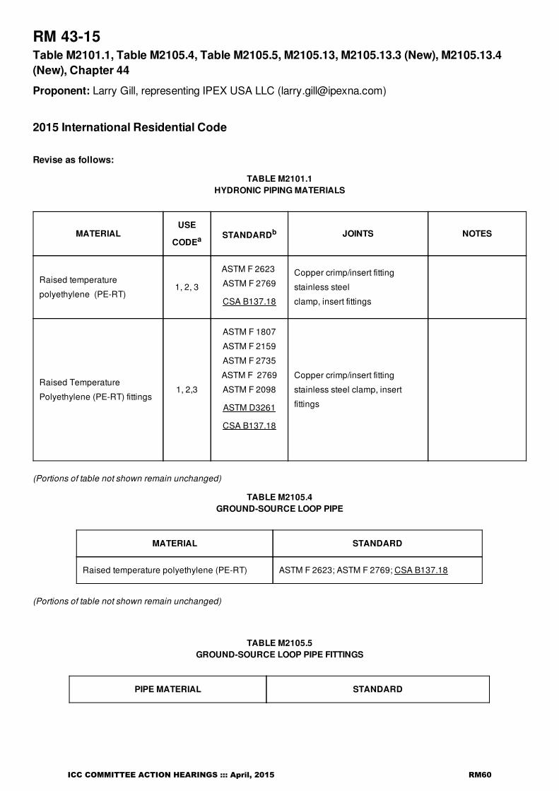
RM 43-15Table M2101.1, Table M2105.4, Table M2105.5, M2105.13, M2105.13.3 (New), M2105.13.4(New), Chapter 44
Proponent: Larry Gill, representing IPEX USA LLC ([email protected])
2015 International Residential Code
Revise as follows:
TABLE M2101.1HYDRONIC PIPING MATERIALS
MATERIALUSE
CODEa STANDARDb JOINTS NOTES
Raised temperature
polyethylene (PE-RT)1, 2, 3
ASTM F 2623
ASTM F 2769
CSA B137.18
Copper crimp/insert fitting
stainless steel
clamp, insert fittings
Raised Temperature
Polyethylene (PE-RT) fittings1, 2,3
ASTM F 1807
ASTM F 2159
ASTM F 2735
ASTM F 2769
ASTM F 2098
ASTM D3261
CSA B137.18
Copper crimp/insert fitting
stainless steel clamp, insert
fittings
(Portions of table not shown remain unchanged)
TABLE M2105.4GROUND-SOURCE LOOP PIPE
MATERIAL STANDARD
Raised temperature polyethylene (PE-RT) ASTM F 2623; ASTM F 2769; CSA B137.18
(Portions of table not shown remain unchanged)
TABLE M2105.5GROUND-SOURCE LOOP PIPE FITTINGS
PIPE MATERIAL STANDARD
ICC COMMITTEE ACTION HEARINGS ::: April, 2015 RM60

RM 43-15 : Table M2101.1-GILL4497
Raised temperature polyethylene (PE-RT)
ASTM D 3261; ASTM F 1807; ASTM F 2159; ASTM F
2769; CSA B137.1; ASTM F1055, ASTM F2098,
ASTM F2735, ASTM D2683, ASTM D3261, CSA
B137.18
(Portions of table not shown remain unchanged)
M2105.13 Raised temperature polyethylene (PE-RT) plastic tubing. Joints between raised temperature polyethylene tubingand fittings shall comply with Sections M2105.13.1, M2105.13.2, M2105.13.3, and M2105.13.2M2105.13.4. Mechanical jointsshall comply with Section M2105.8.1.
Add new text as follows:
M2105.13.3 Heat fusion joints. Heat fusion joints shall be of the socket-fusion, saddle-fusion or butt-fusion type, andshall be joined in accordance with ASTM D2657. Joint surfaces shall be clean and free of moisture. Joint surfacesshall be heated to melt temperatures and joined. The joint shall remain undisturbed until cool. Fittings shall bemanufactured in accordance with ASTM D2683 or ASTM D3261.
M2105.13.4 Electrofusion joints Joints shall be of the electrofusion type. Joint surfaces shall be clean and free ofmoisture and scoured to expose virgin resin. Joint surfaces shall be heated to melt temperatures to a time specifiedby the manufacturer and joined. The joint shall remain undisturbed until cool. Fittings shall be manufactured inaccordance with ASTM F1055.
Add new standard(s) as follows: CSA B137.18 - 2013 - Polyethylene of raised temperature (PE-RT) tubing systemsfor pressure applications.
Reason: Add new CSA B137.18 - Polyethylene of raised temperature resistance (PE-RT) tubing systems for pressure applications to TablesM2101.1, M2105.4, and M2105.5 (scope includes hydronic heating and ground source loop pipe and fittings).Add reference to ASTM D3261which is a consensus standard for PE fusion to Table M2101.1 and Table M2105.5
Add references to ASTM F1055, ASTM F2098, ASTM F2735, and ASTM D2683 to Table M2105.5. ASTM F2098 and ASTM F2735 arealready referenced in the IMC for PE-RT fittings. ASTM F1055 and ASTM D2683 are being added for fused PE joints.
Add new sections M2105.13.3 and M2105.13.4 to permit fusion of PE-RT joints.
The addition of these PE-RT standards will provide alternatives to the standards already in the Code.
Cost Impact: Will not increase the cost of constructionNo cost impact. These changes provide alternatives to PERT pipe and fittings standards only. No changes in cost to the current Codeprovisions.
Analysis: A review of the standard proposed for inclusion in the code, CSA B137.18, with regard to the ICC criteria for referencedstandards (Section 3.6 of CP#28) will be posted on the ICC website on or before April 2, 2015.
ICC COMMITTEE ACTION HEARINGS ::: April, 2015 RM61

RM 44-15 : Table M2101.9-CUDAHY4739
RM 44-15Table M2101.9
Proponent: Mike Cudahy, representing Plastic Pipe and Fittings Association ([email protected])
2015 International Residential CodeRevise as follows:
TABLE M2101.9HANGER SPACING INTERVALS
PIPING MATERIAL
MAXIMUM
HORIZONTAL
SPACING
(feet)
MAXIMUM
VERTICAL
SPACING
(feet)
PEX tubing ≤ 1 inch 2.67 4
PEX tubing ≥ 1 1/4
inches4 10a
(Portions of table not shown remain unchanged)
For SI: 1 inch = 25.4 mm, 1 foot = 304.8 mm.
a. For sizes 2 inches and smaller, a guide shall be installed midway between required vertical supports. Such guides shallprevent pipe movement in a direction perpendicular to the axis of the pipe.
Reason: The 2015 code cycle for the IRC included updates to the support spacing for both PEX and PE-RT tubing for sizes larger than 1".The IRC-P Table P2605.1 is current and correct and should be used as the base template for all other tables within the ICC codes asidentified in this amendment proposal. The horizontal support spacing for both PEX and PE-RT tubing (piping) up to and including 1" size is32" (2-2/3Ft) and 48" (4Ft) for sizes 1- 1/4" and larger. These dimensions are consistent with all published PEX literature and manufacture'sinstallation instructions.
Cost Impact: Will not increase the cost of constructionThis proposal modifies the spacing for piping material support into the code and thus the code with this proposal added will not cause the costof construction to increase, and could decrease the cost as less support is required for larger pipe.
ICC COMMITTEE ACTION HEARINGS ::: April, 2015 RM62

RM 45-15 : M2101.10-CUDAHY4681
RM 45-15M2101.10
Proponent: Mike Cudahy, representing Plastic Pipe and Fittings Association ([email protected])
2015 International Residential CodeRevise as follows:
M2101.10 Tests. Hydronic piping systems shall be tested hydrostatically at a pressure of one and one-half times themaximum system design pressure, but not less than 100 pounds per square inch (689 kPa). The duration of each testshall be not less than 15 minutes and not more than 20 minutes.
Exception: For plastic piping systems, testing with a compressed gas shall be an alternative to hydrostatictesting where compressed air or other gas pressure testing is specifically authorized by all of the manufacturer'sinstructions for the plastic pipe and fittings products installed at the time the system is being tested, andcompressed air or other gas testing is not otherwise prohibited by applicable codes, laws, or regulations outsideof this code.
Reason: PPFA has a new air testing policy, which allows for some limited air testing of plastic piping systems, if a number of conditions aremet.
Bibliography: PLASTIC PIPE AND FITTINGS ASSOCIATION POLICY ON TESTING PLASTIC PIPE AND FITTINGS INSTALLATIONSWITH COMPRESSED GAS, PPFA, 2014, http://www.ppfahome.org/ub4.aspxCompressed air or any other compressed gases should not be used for pressure testing plastic plumbing systems.
EXCEPTIONS:
1.) With trap seal pull testing, where a completed DWV system is vacuum tested with all of its traps filled with water, and the trap seals aretested with a vacuum typically between one and two inches of water column.
2.) For plastic piping systems specifically designed for use with compressed air or gasses;
• Manufacturers' instructions must be strictly followed for installation, visual inspection, testing and use of the systems,
(and)
• Compressed air or other gas testing is not prohibited by the authority having jurisdiction (AHJ).
3.) When compressed air or other gas pressure testing is specifically authorized by the applicable written instructions of the manufacturers ofall plastic pipe and plastic pipe fittings products installed at the time the system is being tested and compressed air or other gas testing is notprohibited by the authority having jurisdiction (AHJ).
The manufacturer should be contacted if there is any doubt as to how a specific system should be tested.
Cost Impact: Will not increase the cost of constructionThis proposal simply adds another option for air testing some specific piping materials into the code and as such, the option is not requiringthat this method be chosen. Thus the code with this proposal added will not cause the cost of construction to increase.
ICC COMMITTEE ACTION HEARINGS ::: April, 2015 RM63

RM 46-15 : M2101.10-MORGAN4930
RM 46-15M2101.10
Proponent: Gary Morgan, Viega LLC, representing Viega LLC ([email protected])
2015 International Residential CodeRevise as follows:
M2101.10 Tests. Hydronic system piping systems shall be tested hydrostatically with either water or, for pipingsystems other than plastic, by air at a pressure of one and one-half times the maximum system design pressure, butnot less than 100 pounds per square inch (689 kPa). The duration of each test shall be not less than 15 minutes andnot more than 20 minutes.
Exception: For plastic piping systems, testing with a compressed gas shall be an alternative to hydrostatictesting where compressed air or other gas pressure testing is specifically authorized by all of the manufacturer'sinstructions for the plastic pipe and fittings products installed at the time the system is being tested, andcompressed air or other gas testing is not otherwise prohibited by applicable codes, laws, or regulations outsideof this code.
Reason: PPFA (Plastic Pipe and Fittings Association) has a new air testing policy, which allows for some limited air testing of plastic pipingsystems if certain conditions are met. The vast majority of plastic pipe used in hydronic applications pose no more of a safety concern thandoes air testing of metallic piping systems. The proposed language is also consistant with new language being proposed by PPFA in the IPCand IRC-P.
Cost Impact: Will not increase the cost of constructionIf anything, allowance of air testing vs. hydrostatic testing will save time and expense typically.
ICC COMMITTEE ACTION HEARINGS ::: April, 2015 RM64

RM 47-15 : M2101.10-MORGAN4994
RM 47-15M2101.10
Proponent: Gary Morgan, Viega LLC, representing Viega LLC ([email protected])
2015 International Residential CodeRevise as follows:
M2101.10 Tests. Hydronic piping systems shall be tested hydrostatically at a pressure of one and one-half times themaximum system design pressure, but not less than 100 pounds per square inch (689 kPa). The duration of each testshall be not less than 15 minutes and not more than 20 minutes.
Reason: To limit the maximum time of pressure testing to 20 minutes (when the minimum time is already only 15 minutes) is not consistantwith industry practice nor is it consistant with the IMC 1208.1 for testing of hydronic systems where no such maximum time even exists.
Cost Impact: Will not increase the cost of constructionEliminating the maximum time of testing requirement has absolutely no bearing on the cost of construction.
ICC COMMITTEE ACTION HEARINGS ::: April, 2015 RM65

RM 48-15 : M2103.2-URSENBACH5803
RM 48-15M2103.2, M2103.2.1, M2103.2.2
Proponent: Brent Ursenbach, Salt Lake County, representing Utah Chapter ICC ([email protected])
2015 International Residential CodeRevise as follows:
M2103.2 Thermal barrier required. Radiant floor heating systems shall have a thermal barrier in accordance withSections M2103.2.1 through M2103.2.4. Insulation R-values for slab-on-grade and suspended floor installations shallbe in accordance with the International Energy Conservation Code.
Exception: Insulation shall not be required in engineered systems where it can be demonstrated that theinsulation will decrease the efficiency or have a negative effect on the installation.
Delete without substitution:
M2103.2.1 Slab-on-grade installation. Radiant piping used in slab-on-grade applications shall have insulatingmaterials having a minimum R-value of 5 installed beneath the piping.
M2103.2.2 Suspended floor installation. In suspended floor applications, insulation shall be installed in the joist baycavity serving the heating space above and shall consist of materials having a minimum R-value of 11.
Reason: Insulation R-values should be located in the IECC/Chapter 11, not Chapter 21- Hydronic Piping. Design professionals, codeofficials, contractors, developers, virtually all involved in the building process look to the IECC/Chapter 11 for specfic thermal performancevalues. Locating these two sub-sections in the IMC has created considerable confusion. A similiar proposal will be submitted in Grouip B, toadd these sub-sections into the IECC where they belong.
Cost Impact: Will not increase the cost of constructionThis proposal will not increase the cost of construction as it is the first step in re-locating an existing insulation requirement from the IRCmechanical section to the IECC/Chapter 11 IRC. There is no increase in the R-value of the insulation or the installation labor.
ICC COMMITTEE ACTION HEARINGS ::: April, 2015 RM66

RM 49-15 : M2103.3-EARL4643
RM 49-15M2103.3
Proponent: Tim Earl, GBH International, representing The Oatey Company ([email protected])
2015 International Residential CodeRevise as follows:
M2103.3 Piping joints. Copper and copper alloy systems shall be soldered in accordance with ASTM B 828. Fluxesfor soldering shall be in accordance with ASTM B 813. The base material for tinning fluxes, excluding the tinningpowder, shall meet the criteria of ASTM B813. Brazing fluxes shall be in accordance with AWS A5.31. Piping jointsthat are embedded shall be installed in accordance with the following requirements:
1. Steel pipe joints shall be welded.2. Copper tubing shall be joined by brazing complying with Section P3003.6.1.3. Polybutylene pipe and tubing joints shall be installed with socket-type heat-fused polybutylene fittings.4. CPVC tubing shall be joined using solvent cement joints.5. Polypropylene pipe and tubing joints shall be installed with socket-type heat-fused polypropylene fittings.6. Cross-linked polyethylene (PEX) tubing shall be joined using cold expansion, insert or compression
fittings.7. Raised temperature polyethylene (PE-RT) tubing shall be joined using insert or compression fittings.
Reason: Tinning fluxes have been shown in several studies to create a stronger and more consistently water-tight connection when usinglow-lead fittings. This means less rework on the job site and less likelihood of joint failure. With the federal mandate of low-lead in 2014, thishas become a significant issue and the codes need to reflect this need. We are pursuing changes to the referenced ASTM standard as well,however these will not be completed in time for this code cycle and we feel that it is important to make this change as it has the potential tosave money related to rework and repair. Once the standard is altered, we would support removing the language being proposed.
Cost Impact: Will not increase the cost of constructionThis proposal will not affect cost as it simply adds another solder flux option.
ICC COMMITTEE ACTION HEARINGS ::: April, 2015 RM67

RM 50-15Table M2105.4, Table M2105.5, Chapter 44
Proponent: Jeremy Brown, representing NSF International ([email protected])
2015 International Residential CodeRevise as follows:
TABLE M2105.4GROUND-SOURCE LOOP PIPE
MATERIAL STANDARD
Chlorinated polyvinyl chloride
(CPVC)
ASTM D 2846; ASTM F 437; ASTM F 438; ASTM F
439;
ASTM F 441; ASTM F 442; CSA B137.6
Cross-linked polyethylene
(PEX)
ASTM F 876; ASTM F 877
CSA B137.5; NSF 358-3
Polyethylene/aluminum/polyethylene (PE-AL-
PE) pressure pipeASTM F 1282; CSA B137.9; AWWA C 903
High-density Polyethylene (HDPE)ASTM D 2737; ASTM D 3035; ASTM F 714;
AWWA C901; CSA B137.1; CSA C448; NSF 358-1
Polypropylene (PP-R) ASTM F 2389; CSA B137.11
Polyvinyl chloride (PVC) ASTM D 1785; ASTM D 2241; CSA 137.3
Raised temperature polyethylene (PE-RT) ASTM F 2623; ASTM F 2769
TABLE M2105.5GROUND-SOURCE LOOP PIPE FITTINGS
PIPE MATERIAL STANDARD
Chlorinated polyvinyl chloride (CPVC)ASTM D 2846; ASTM F 437; ASTM F 438; ASTM F
439; ASTM F 1970; CSA B137.6
Cross-linked polyethylene
(PEX)
ASTM F 877; ASTM F 1807; ASTM F 1960; ASTM F
2080;
ASTM F 2159; ASTM F 2434; CSA B137.5; NSF 358-3
Polyethylene/aluminum/polyethylene PE-AL-
PE)ASTM F 2434; ASTM F 1282; CSA B137.9
High-density Polyethylene (HDPE)ASTM D 2683; ASTM D 3261; ASTM F 1055; CSA
B137.1; CSA C448; NSF 358-1
Polypropylene (PP-R) ASTM F 2389; CSA B137.11; NSF 358-2
ICC COMMITTEE ACTION HEARINGS ::: April, 2015 RM68

RM 50-15 : Table M2105.4-BROWN5479
Polyvinyl chloride (PVC)ASTM D 2464; ASTM D 2466; ASTM D 2467; ASTM F
1970, CSA B137.2; CSA B137.3
Raised temperature polyethylene (PE-RT)ASTM D 3261; ASTM F 1807; ASTM F 2159; F 2769;
B137.1
Add new standard(s) as follows: NSF 358-3 (DRAFT 10-7-2014) Cross-linked Polyethylene (PEX) Pipe and Fittings for Water-Based Ground-Source(Geothermal) Heat Pump Systems
Reason: NSF 358-3 Cross-linked Polyethylene (PEX) Pipe and Fittings for Water-Based Ground-Source (Geothermal) Heat Pump Systemsis currently under development as of the submittal deadline. This will be the American National Standard for PEX system components used ingeothermal systems and when completed should be referenced in this table. This standard will have geothermal specific requirements aboveand beyond the ASTM standards for PEX. This standard is expected to be completed in 2015. A draft may be obtained from Jeremy Brown [email protected].
Cost Impact: Will not increase the cost of constructionAdding another option for standards will not increase the cost of construction.
Analysis: A review of the standard proposed for inclusion in the code,NSF 358-3 , with regard to the ICC criteria for referencedstandards (Section 3.6 of CP#28) will be posted on the ICC website on or before April 2, 2015.
ICC COMMITTEE ACTION HEARINGS ::: April, 2015 RM69

RM 51-15 : Table M2105.4-BROWN5477
RM 51-15Table M2105.4, Table M2105.5
Proponent: Jeremy Brown, representing NSF International
2015 International Residential CodeRevise as follows:
TABLE M2105.4GROUND-SOURCE LOOP PIPE
MATERIAL STANDARD
Polypropylene (PP-R) ASTM F 2389; CSA B137.11; NSF 358-2
(Portions of table not shown remain unchanged)
TABLE M2105.5GROUND-SOURCE LOOP PIPE FITTINGS
PIPE MATERIAL STANDARD
Polypropylene (PP-R) ASTM F 2389; CSA B137.11; NSF 358-2
(Portions of table not shown remain unchanged)
Add new standard(s) as follows: NSF 358-2-2012 Polypropylene Pipe & fittings for water-based ground-source "geothermal" heat pump systems
Reason: NSF 358-2 Polypropylene Pipe & fittings for water-based ground-source "geothermal" heat pump systems is the American Nationalstandard and should be included in these tables. This standard has requirements for material suitability, performance, chemical resistancelong term strength and quality assurance requirements related to geothermal products. A copy of this standard will be provided to thecommitee and may be obtained by anyone else by emailing [email protected].
Cost Impact: Will not increase the cost of constructionProviding an additional option will not increase the cost of construction.
Analysis: A review of the standard proposed for inclusion in the code, NSF 358-2, with regard to the ICC criteria for referenced standards(Section 3.6 of CP#28) will be posted on the ICC website on or before April 2, 2015.
ICC COMMITTEE ACTION HEARINGS ::: April, 2015 RM70

RM 52-15M2005.1, M2301.2.1, M2301.2.2.2, M2301.2.4, M2301.2.6, M2301.2.8, M2301.2.11.1, M2301.3,M2301.3.1, M2301.3.2, M2301.2.6.1 (New), M2301.2.6.2 (New)
Proponent: Rex Gillespie ([email protected])
2015 International Residential CodeRevise as follows:
M2005.1 General. Water heaters shall be installed in accordance with Chapter 28, the manufacturer's instructions andthe requirements of this code. Water heaters installed in an attic shall comply with the requirements of SectionM1305.1.3. Gas-fired water heaters shall comply with the requirements in Chapter 24. Domestic electric water heatersshall comply with UL 174. Oiled-fired water heaters shall comply with UL 732. Thermal solarSolar thermal waterheatersheating systems shall comply with Chapter 23 and UL 174SRCC 300. Solid fuel-fired water heaters shallcomply with UL 2523.
M2301.2.1 Access. Solar energy collectors, controls, dampers, fans, blowers and pumpsAccess shall be accessible provided to solar energy equipment for inspection, maintenance, repairmaintenance. Solarsystems and replacementappurtenances shall not obstruct or interfere with the operation of any doors, windows orother building components requiring operation or access. Roof-mounted solar thermal equipment shall not obstructor interfere with the operation of roof-mounted equipment, appliances, chimneys, plumbing vents, roof hatches, smokevents, skylights and other roof penetrations and openings.
M2301.2.2.2 Collector sensors. Collector sensor installation, sensor location and the protection of exposed sensorwires from ultraviolet light degradation shall be in accordance with SRCC 300.
M2301.2.4 Vacuum relief. System components that might be subjected to pressure drops below atmosphericpressure a vacuum during operation or shutdown shall be designed to withstand such vacuum or shall be protected bya vacuum-relief valve. with vacuum relief valves.
M2301.2.6 Protection from freezing. System components shall be protected from damage resulting from freezing ofheat-transfer liquids at the winter design temperature provided in Table R301.2(1). Freeze protection shall be providedby heating, insulation, thermal mass and heat transfer fluidsin accordance with SRCC 300. Drain-back systems shallbe installed in compliance with Section M2301.2.6.1 and systems utilizing freeze points lower than the winter designtemperature, heat tape or other approved methods, or combinations thereof.protection valves shall comply withSection M2301.2.6.2.
Exception: Where the 97.5-percent winter design temperature is greater than 32or equal to 48°F (09°C).
M2301.2.8 Expansion tanks. Expansion tanks in solar energy systems shall be installed in accordance with SectionM2003 in solar collector loops that contain pressurized heat transfer fluid. Where expansion tanks are used, thesystem shall be designed in accordance with SRCC 300 to provide an expansion tank that is sized to withstand themaximum operating pressure of the system.
Exception: Expansion tanks shall not be required in the collector loop of drain-back systems.
M2301.2.11.1 Solar loop isolation. Valves shall be installed to allow the solar collectors loop to be isolated from theremainder of the system
M2301.3 Labeling. Labeling shall comply with Sections M2301.3.1 and M2301.3.2.
M2301.3.1 Collectors and panels. Solar thermal collectors and panels shall be listed and labeled in accordance withSRCC 100 or SRCC 600. Collectors and panelsFactory-built collectors shall be listed and labeled to showbear a labelshowing the manufacturer's name, model number, and serial number, collector weight, collector maximum allowabletemperatures and pressures, and the type of heat transfer fluids that are compatible with the collector or panel. Thelabel shall clarify that these specifications apply only to the collector or panel.
M2301.3.2 Thermal storage units. Pressurized thermal water storage units tanks shall be listed and labeled to showbear a label showing the manufacturer's name and address, model number, serial number, storage unit maximum andminimum allowable operating temperatures and pressures,storage unit maximum and the type of heat transfer fluidsthat are compatible with the storage unitminimum allowable operating pressures. The label shall clarify that thesespecifications apply only to the thermal water storage unittanks.
ICC COMMITTEE ACTION HEARINGS ::: April, 2015 RM71

RM 52-15 : M2301.2.1-GILLESPIE4041
Add new text as follows:
M2301.2.6.1 Drain-back systems Drain-back systems shall be designed and installed to allow for manual gravitydraining of fluids from areas subject to freezing to locations not subject to freezing, and air filling of the componentsand piping. Such piping and components shall maintain a horizontal slope in the direction of flow of not less than one-fourth unit vertical in 12 units horizontal (2-percent slope). Piping and components subject to manual gravity drainingshall permit subsequent air filling upon drainage and air venting upon refilling.
M2301.2.6.2 Freeze protection valves. Freeze protection valves shall discharge in a manner that does not create ahazard or structural damage.
Reason: A reference to the SRCC 300 standard was added to the IRC in Chapter 23 during the 2015 cycle. This change in Chapter 20changes to language to correspond to SRCC 300. Requirements for hot water storage tanks, which UL 174 intended to address are coveredin SRCC 300, therefore, UL 174 is no longer necessary.Access provisions were revised to clarify that roof-mounted solar collectors and equipment should not interfere with the operation of keysafety components and features from other systems. While this can reasonably assumed, providing this provisions will provide code officialsmore clear language to reference when inspecting installations.
New language has been added to the freeze protection section to address specific issues with two of the most common freeze protectionapproachs: drainback systems and freeze protection valves. Drainback systems allow the liquid to drain from the external collector toconditioned space when flow is not occuring. As a result proper slope is critical to ensure operation. Inspection of the installation andworkmanship is necessary to ensure that the slope is consistent and the freeze protection is fully functional. Freeze protection valvesdischarge a small amount of water in freezing conditions and therefore should be addressed in a way similar to T&P valves to ensure that thedischarge does not damage the roof or create a hazard (e.g. freezing on a pedestrian walkway). Identical language has also been proposedfor Chapter 14 of the IMC. The winter design temperature was revised to utilize the 97.5% winter design temperature, which can be found inAppendix D of the IPC. The threshold value was adjusted to accomodate this change. This will provide greater clarity and allow the AppendixD tables to be used.
The provisions relating to collector and hot water storage tank labeling were simplified since this information and more can be found inmanuals and specifications. The language for storage units (tanks) was also revised to clarify that they are only to apply to hot water storagetanks.
Bibliography: SRCC 300, Minimum Standards for Solar Water Heating Systems, Jan. 2, 2013.
Cost Impact: Will not increase the cost of constructionThe proposed changes are not anticipated to impact the cost of installation. No new equipment or features are required, and no newrequirements are placed on manufacturers impacting certification or manufacturing costs. Proposed provisions provide additional clarity anddirection for installers and code officials at inspection.
ICC COMMITTEE ACTION HEARINGS ::: April, 2015 RM72

RM 53-15 : M2301.3.3 (New)-SCHWARZ4982
RM 53-15M2301.3.3 (New)
Proponent: Robby Schwarz, EnergyLogic, Inc., representing EnergyLogic, Inc. ([email protected])
2015 International Residential CodeAdd new text as follows:
M2301.3.3 Labeling of solar energy systems The solar energy installer shall provide a certificate or label that liststhe following information relative to the installed solar system: Such certificate or label shall be posted near theinverter, electrical distribution panel, or other conspicuous location.
1. The date that the system was installed.2. The name of the installation company.3. The system type.4. The orientation of the arrays and collectors.5. The tilt in degrees of the arrays and collectors.6. The square foot area of the arrays and collectors.7. The number of panels in the arrays.8. The peak power production of the arrays and collectors stated in watts.9. The inverter efficiency of the arrays and collectors.10. The loop type of the arrays and collectors.11. The type of the arrays and collectors.12. The storage volume of the system in cubic feet or gallons.
Reason: Rational Statement:Just like the requirement to provide an insulation certificate to fully document the R-values of the insulation in each assembly of the homeensures that the code official and home owner knows and understand what has been installed in the home, this proposal ensures thateveryone involved knows and understands the PV or solar thermal system that has been installed. In addition, since the requirement is inlabel form it is hoped that this Permanente label will live with the house and will provide meaning full information that can be used for repairsand upgrades, as well as, appraisals and sales transactions when the house is turned over.
Cost Impact: Will not increase the cost of constructionThe cost of a label is so minimal that it should not be considered increasing the cost of construction.
ICC COMMITTEE ACTION HEARINGS ::: April, 2015 RM73

RM 54-15 : M2301.4-GILLESPIE5131
RM 54-15R202 (New), M2301.4.1.1 (New), M2301.4.1.2 (New)
Proponent: Rex Gillespie ([email protected])
2015 International Residential CodeAdd new definition as follows:
SECTION 202 DEFINITIONS
FOOD GRADE FLUID. Potable water or a fluid containing additives listed in accordance with the Code of FederalRegulations, Title 21, Food and Drugs, Chapter 1, Food and Drug Administration, Parts 174-186
SECTION 202 DEFINITIONS
NON-FOOD GRADE FLUID. Any fluid that is not designated as a food grade fluid.
Add new text as follows:
M2301.4.1.1 Double-wall heat exchangers. Heat exchangers utilizing a non-food grade fluid shall separate the non-food grade fluid from the potable water by means of double-wall construction. An air gap open to the atmosphere shallbe provided between the two walls. The point of discharge from the air gap between the two walls of the double-wallheat exchanger shall be visible.
M2301.4.1.2 Single-wall heat exchangers. Where single-wall heat exchangers are used, the heat transfer fluid shallbe food grade fluid..
Reason: This proposal seeks to align with the language that appears in the IMC Chapter 1402.8 regarding heat exchangers and adddefinitions of FOOD GRADE and NON-FOOD GRADE heat transfer fluids as stated in SRCC Standard 300
Bibliography: SRCC Standard 300, Minimum Standard for Solar Thermal Water Heating Systems, January 3, 2013.
Cost Impact: Will not increase the cost of constructionThe proposed changes are not anticipated to impact the cost of installation. No new equipment or features are required, and no newrequirements are placed on manufacturers impacting certification or manufacturing costs. Proposed provisions provide additional clarity anddirection for installers and code officials at inspection.
Analysis: A review of the standard proposed for inclusion in the code, CFR Title 21, Chapter 1, Parts 174-186, with regard to the ICC criteriafor referencedstandards (Section 3.6 of CP#28) will be posted on the ICC website on or before April 2, 2015.
ICC COMMITTEE ACTION HEARINGS ::: April, 2015 RM74