iranian journal of hydrogen & fuel cell ijhfc
TRANSCRIPT

Iranian Journal of Hydrogen & Fuel Cell 4(2017) 265-274
Iranian Journal of Hydrogen & Fuel Cell
IJHFCJournal homepage://ijhfc.irost.ir
Parametric study of the in uence of cooling channel dimensions on PEM fuel cell thermal performance
Ebrahim Afshari 1,*, Nabi Jahantigh2, Masoud Ziaei-Rad1
1Department of Mechanical Engineering, Faculty of engineering, University of Isfahan, Isfahan, Iran. 2Department of Mechanical Engineering, Faculty of engineering, University of Zabol, Zabol, Iran.
Article Information Article History:
Received:05 Nov 2017Received in revised form:11 Jan 2018Accepted:15 Jan 2018
Keywords
Polymer membrane fuel cellCooling ow eldThe temperature distributionUniform temperature distributionPressure dropParametric study
Abstract
In a polymer membrane fuel cell more than half of the chemical energy of hydrogen is converted to heat during generation of electricity. This causes an increase in the cell temperature. The cooling eld design has a signi cant role in cell cooling. The cell’s performance and stability are reduced due to inappropriate heat dissipation. In this paper, the cooling ow and heat transfer in cooling plates with parallel channels in the polymer membrane fuel cell are simulated and a parametric study of the in uence of the cooling channels dimensions on the fuel cell thermal performance is performed based on three indexes: maximum surface temperature cooling (Tmax), the temperature uniformity on the surface (UT), and pressure drop. Numerical results show that increasing the depth of the channels has an adverse effect on temperature characteristics; in addition, the pressure drop decreases. Therefore regarding constructional limitations and mechanical strength, use of channels with a depth of 1 mm is recommended. Increasing the width of the channels decreases the maximum surface temperature of the cooling plate, the temperature uniformity index, and the pressure drop. However, increasing the channel width more than 3mm does not have a signi cant effect on the cooling performance. Increasing the distance between two channels adversely effects the thermal parameters as well as increases the pressure drop. Therefore, the distance between two cooling channels should not be more than 2 mm.
*Corresponding Author’s Fax: +983137934549E-mail address: [email protected]
doi: 10.22104/ijhfc.2018.2565.1158
1. Introduction
The advantages of the polymer membrane fuel cells, such as high ef ciency, low-performance temperature,
temperature, unprotected electrical energy generation, high energy density, variety, and short running time make them a power generation option for transport vehicles [1].
Iranian Journal of Hydrogen & Fuel Cell 4(2017) 265-274266
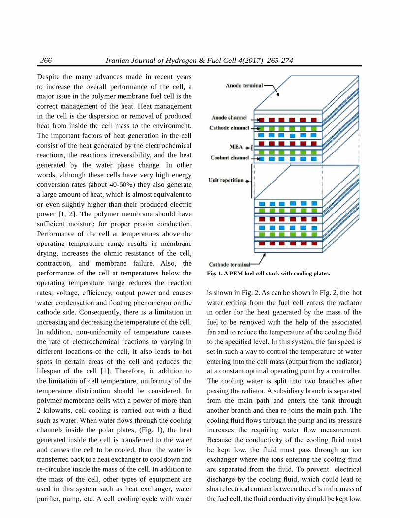
Despite the many advances made in recent years to increase the overall performance of the cell, a major issue in the polymer membrane fuel cell is the correct management of the heat. Heat management in the cell is the dispersion or removal of produced heat from inside the cell mass to the environment. The important factors of heat generation in the cell consist of the heat generated by the electrochemical reactions, the reactions irreversibility, and the heat generated by the water phase change. In other words, although these cells have very high energy conversion rates (about 40-50%) they also generate a large amount of heat, which is almost equivalent to or even slightly higher than their produced electric power [1, 2]. The polymer membrane should have suf cient moisture for proper proton conduction. Performance of the cell at temperatures above the operating temperature range results in membrane drying, increases the ohmic resistance of the cell, contraction, and membrane failure. Also, the performance of the cell at temperatures below the operating temperature range reduces the reaction rates, voltage, ef ciency, output power and causes water condensation and oating phenomenon on the cathode side. Consequently, there is a limitation in increasing and decreasing the temperature of the cell. In addition, non-uniformity of temperature causes the rate of electrochemical reactions to varying in different locations of the cell, it also leads to hot spots in certain areas of the cell and reduces the lifespan of the cell [1]. Therefore, in addition to the limitation of cell temperature, uniformity of the temperature distribution should be considered. In polymer membrane cells with a power of more than 2 kilowatts, cell cooling is carried out with a uid such as water. When water ows through the cooling channels inside the polar plates, (Fig. 1), the heat generated inside the cell is transferred to the water and causes the cell to be cooled, then the water is transferred back to a heat exchanger to cool down and re-circulate inside the mass of the cell. In addition to the mass of the cell, other types of equipment are used in this system such as heat exchanger, water puri er, pump, etc. A cell cooling cycle with water
Fig. 1. A PEM fuel cell stack with cooling plates.
is shown in Fig. 2. As can be shown in Fig. 2, the hot water exiting from the fuel cell enters the radiator in order for the heat generated by the mass of the fuel to be removed with the help of the associated fan and to reduce the temperature of the cooling uid to the speci ed level. In this system, the fan speed is set in such a way to control the temperature of water entering into the cell mass (output from the radiator) at a constant optimal operating point by a controller. The cooling water is split into two branches after passing the radiator. A subsidiary branch is separated from the main path and enters the tank through another branch and then re-joins the main path. The cooling uid ows through the pump and its pressure increases the requiring water ow measurement. Because the conductivity of the cooling uid must be kept low, the uid must pass through an ion exchanger where the ions entering the cooling uid are separated from the uid. To prevent electrical discharge by the cooling uid, which could lead to short electrical contact between the cells in the mass of the fuel cell, the uid conductivity should be kept low.

Iranian Journal of Hydrogen & Fuel Cell 4(2017) 265-274 267
The cooling channels inside the polar plates should be designed in such way to satisfy the following conditions simultaneously.1-Removal of generated heat at different operating voltages: The heat generated by the mass of the cell changes with variation in the output electrical power. This heat increases as the output ow increases. Because the cell may operate at different voltages, the cooling ow eld should be able to remove generating heat at these different voltages.2-The minimum pressure drop of cooling uid in the direction of the cooling eld: The consumption power of the cooling uid rotating pump in the heat management system increases as the pressure drop increases in the direction of the eld. This causes a decrease in the generated electrical power of the fuel cell. Therefore, the cooling ow eld should be designed in such way to minimize the amount of pressure drop.3- Uniform temperature distribution: Since the rate of electrochemical reactions as well as the ow density at a working voltage is dependent on temperature, the temperature distribution along the active surface of the cell should be uniform so that the reaction rate and ow density in the active surface of the cell can be uniformed. The non-uniform distribution of ow density results in damage to the membrane-electrode
assembly. Maintaining a uniform distribution of temperature at the active level of the cell is one of the key parameters in designing a cooling ow eld [3-9]. In fact, high heat dissipation, uniform distribution of temperature and low-pressure drop are very important in the design of the cooling ow eld. Different patterns to satisfy these three objectives can be considered in ow channels for cooling the mass of the cell with water. Flow elds with parallel, spiral, and spiral-parallel channels are more common [10-13]. Parallel channels are the simplest types of canals. The machining cost of these types of canals and their pressure drop are much lower than spiral channels, although the temperature distribution is more non-uniform. To take advantages of these two facts, their geometric dimensions need to be optimized to improve their thermal properties. The studies done so far on cooling channels have been related to different patterns of canals. In these studies, different comparisons of spiral canals with parallel channels have been investigated but eld optimization with parallel channels has not been investigated. In this paper, optimization of geometric dimensions of simple parallel canals and the effect of depth, width, and distance between canals on thermal performance of the cell have been investigated.
Fig. 2. The cooling circuit schematic of a PEM fuel cell.

Iranian Journal of Hydrogen & Fuel Cell 4(2017) 265-274268
2.Model description
Several single-fuel cells have been put together in order to achieve the desired power of the cell and the cell mass has been constructed. As shown in Fig. 1, a single cell consists of a membrane set for conducting ions, catalyst layers for performing electrochemical reactions, two gas diffusion layers for reactive distribution, and two polar plates for conducting electrons and ow distribution. In fact, channels for reactive gas ow and the cooling channels are created inside the polar plates. Heat dissipation from the electrochemical reactions is very important for proper performance of the cell . It is usually carried out by liquid water embedded in cooling channels in polar plates or special cooling plates [2].In the cell permanent function, the average thermal ux of a cooling plate (two cooling surfaces) can be obtained by equation (1) [3].
(1)
The letters n, I, V, A, and F are respectively, the number of single cells per cooling plate, current, output voltage, total cell surface, enthalpy of water formation and Faraday constant. As shown in Fig. 3, the computational domain is part of the cooling plate with a 15 ×15 cm2 area in such a way that the cooling channels are embedded in this cooling plate. In fact, the heat generated in the cell is simulated
as a heat flux which enters over the surface of the cooling plate [2]. The cooling flow field studied (base model) consists of a flow field with 37 parallel channels. In addition to the base model, the performance of this field has been studied using different dimensions of channel depth, channel width, and the distance between two channels. The geometric model and boundary conditions have been shown in Fig. 3. Also, the parameters used to simulate the cooling plate are presented in Table 1. In this table, the NEXA membrane cell (Ballard Power) with 1.2kW power is chosen, for this cell the heat flux is 5000W/m2 [4].
Table 1. Parameters used for simulation [3]Geometry of plate
2mm×150mm×150mmDimensions of plate2mmWidth of channel2mmDistance between two channels
0.5mmDepth of channels Cooling plate properties (Graphite)
2250 kg/m3ρ690 J/kg.KCp 24 W/m.KK
Cooling Properties (water) 40° C 922.2 kg/mρ4179 J/kg.KCp0.62 W/m.KK
Operating conditions5000 W /m2Heat Flux
40 °C Cooling input Temperature0.0012 kg/sCooling input mass ow rate
22
fh
nI( V )FqA
Fig. 3. Geometric model with boundary conditions.
fh
nI( V )

Iranian Journal of Hydrogen & Fuel Cell 4(2017) 265-274 269
3.The governing equation, boundary conditions, and numerical solution method
The governing equations for cooling uid ow, consisting of the Continuity equation, Momentum equation, and Energy conservation equation, should be solved in the cooling plates and uid. Given the geometry of the problem and the Reynolds number (Reynolds number is 330), it is assumed that the ow is laminar and uid is incompressible. Transient terms are not considered in conservation equations due to the cooling permanent function. For the solid region, the energy equation becomes the pure thermal conductivity equation. In order to reduce calculation time, only half of the cooling plate is simulated. In other words, the symmetry boundary condition is used for the top surface of the plate. For the lower surface of the plate, the constant heat ux condition is used. The inlet and outlet boundary conditions for cooling uid are considered the specied mass ow inlet and outlet. The ow eld is considered fully developed. The edges of the cooling plates have free convection heat transfer with the environment. The two edges of the page are in the vertical direction and the other two edges are in the horizontal direction. The inlet temperature of the inlet cooling uid and the approximate temperature of the cooling plates at the edges is 40°C. Based on the empirical relationships the convection heat transfer coefcient in the vertical edges, the upper and lower horizontal edges equal 5.5, 8.2 and 6.1 W/m.K, respectively. Numerical simulation of the ow eld and heat transfer in plates has been done using FLUENT software. The Continuity, Momentum, and Energy equations have been solved based on nite element methods. The SIMPLE algorithm is used for velocity and pressure coupling and the second order upwind method is considered for the discretization of equations. The independence of results to the number of grids has been investigated based on parameters such as the pressure drop and the maximum surface temperature. In order to investigate the dependence of the results to the number of grids, the dependence of the pressure drop and the maximum surface temperature to the
number of grids has been investigated. It has been indicated that the drop pressure and the maximum temperature are not dependent on the number of grids when the number of computational grids is about 1200,000.
4.Results and discussion
In order to validate the numerical model, the Darcy friction factor and the Nusselt number have been investigated for a simple single channel and have been compared with the analytical results. Fig. 4 shows the value of the parameters, such as Nusselt numbers and friction coefcient, along a single channel.
Fig. 4. Nusselt number and Darcy friction factor cross Reynolds number (f.Re) along a straight channel with the aspect ratio of 2.
The hydraulic and thermal entrance lengths are obtained by using empirical relationships when the Reynolds number is equal to 330. These parameters obtained equal 0.0219 and 0.089, respectively. The amount of the f.Re and Nu number after the entrance length rapidly reach 61 and 4.93, which are in good agreement with the reference values of 62 and and 4.12 for a fully-developed laminar ow through a rectangular channel with the aspect ratio of 2 [14]. The investigation of the effect of the cross-section dimensions of the channels (the depth and width of

Iranian Journal of Hydrogen & Fuel Cell 4(2017) 265-274270
Fig. 5. The temperature distribution in the cooling plate with dimensions of 15x15 mm2, a channel with a width and depth equal to 2mm and 1mm.
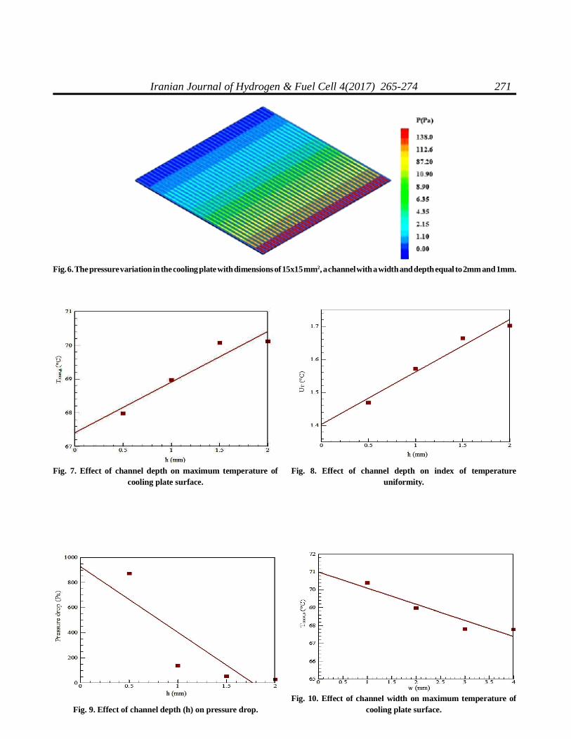
and keeping the temperature distribution uniform throughout the active cell surface. Fig. 6 depicts the cooling pressure drop in the cooling ow eld in a Pa unit, in which due to the lack of bend, low ow velocity, and short pass-line length the pressure drop is very low.The effect of channel depth on the maximum temperature of cooling plate surface, index of temperature uniformity, and pressure drop have been presented in Fig.s 7 to 9, respectively. Also, the effect of the channel width on the maximum temperature of cooling plate surface, index of temperature uniformity, and pressure drop have been presented in Fig.s 10 to 12, respectively. Summary of numerical solution results based on the channel depth and width changes have presented in Tables 2 and 3.As shown in Fig.s 5 to 7 and Table 2, increasing the channel depth increases the maximum temperature of the cooling plate surface and the index of temperature uniformity and decreases the pressure drop. As shown in Fig.s 8 to 10, the increase in channel widths reduces the maximum temperature of the cooling plate surface, the index of temperature uniformity, and the pressure drop. Therefore, increasing the depth of the channel in terms of thermal indices is not desirable, although it decreases the amount of pressure drop. It is concluded that the lower the
the channels) on the cooling performance has been done in two cases.1. The performance of a direct parallel cooling ow eld with a rectangular cross-section has been investigated in such a way that the channel depth is constant and the width of the channel varies.2. The performance of a direct parallel cooling ow eld with a rectangular cross-section has been investigated in such a way that the channel width is constant and the depth of channel varies. In both cases, the distance between the two channels and the length and width of the cooling plate have been considered constant. The cooling plate dimensions of the primary eld as the basis for comparison are presented in Table 1. To ensure the thermal stability of the cell, the maximum temperature of the cooling plate surface should be maintained at a determined level. Therefore, the maximum surface temperature is the most important factor to prevent thermal damage of the cell. Also, to better compare cooling performance, the index of temperature uniformity is dened as follows [2].
(2)
T is the temperature of the surface and Tavg is the average temperature of the heat transfer surface of the cooling plate. The index of temperature uniformity shows the temperature deviation from the average temperature of the heat transfer surface quantitatively. In other words, when the temperature distribution is completely uniform, the value of UT
is zero.Fig. 5 displays the temperature distribution in the central surface of a cooling plate (symmetrical boundary) with dimensions 15x15 and a channel with a width and depth equal to 2mm and 1mm. Along the channel length, the water temperature increases because of heat absorption of the cell in such a way that the maximum temperature happens at the ends of the channels. The role of the cooling plates is to prevent excessive heating by proper removal of reaction heat,
avgA AT avg
A A
TdAT T dAU ,T
dA dA
271Iranian Journal of Hydrogen & Fuel Cell 4(2017) 265-274
Fig. 6. The pressure variation in the cooling plate with dimensions of 15x15 mm2, a channel with a width and depth equal to 2mm and 1mm.
Fig. 7. Effect of channel depth on maximum temperature of cooling plate surface.
Fig. 9. Effect of channel depth (h) on pressure drop.
Fig. 8. Effect of channel depth on index of temperature uniformity.
Fig. 10. Effect of channel width on maximum temperature of cooling plate surface.

Iranian Journal of Hydrogen & Fuel Cell 4(2017) 265-274272
Table 2. Summary of numerical solution results based on the channel depth changes.∆P
(Pa)ΔTcoolant
(°C)UT
(°C)Tavg, surface
(°C)ΔTsurface
(°C)Tmin, surface
(°C)Tmax, surface
(°C)Number of channelsChannel width
w (mm)Channel depth
d (mm)871.3418.3101.46965.2537.81061.17067.9803720.5138.1418.7081.57166.1277.30361.66768.9703721.052.7019.5841.66466.7088.34061.73570.0753721.527.6749.6731.70266.7307.77262.34570.1173722.0
Table 3. Summary of numerical solution results based on the channel width changes.∆P
(Pa)ΔTcoolant
(°C)UT
(°C)Tavg, surface
(°C)ΔTsurface
(°C)Tmin, surface
(°C)Tmax, surface
(°C)Number of channelsChannel depth
d (mm) Channel width
w (mm)340.0349.6351.65466.1668.89661.50170.3974911138.1418.7081.57166.1277.30361.66768.970371297.4607.6051.48566.0376.29661.51867.814301381.6277.5601.46965.9136.30461.47467.7782514
Fig. 12. Effect of channel width on pressure drop.Fig. 11. Effect of channel width on index of temperature
uniformity.
depth of the channels is the more appropriate it is for the channels. However, due to machining problems it is not possible to reduce the depth of the channel too much. There is not a signicant difference in the values of pressure drop at depths of 1, 1.5 and 2 mm. The use of a channel with a depth of 0.5 mm is also not recommended due to construction problems and mechanical resistance reduction. Therefore, it is better to use channels with a depth of 1 mm. Increasing the width of the channels reduces the values of all the performance parameters such as the maximum temperature, the average temperature, the temperature difference of the cooling plate surface, the cooling temperature decrement rate, the index of temperature uniformity, and the pressure drop. Increasing the channel width more than 3 mm does
not have much of an effect on cooling performance. As the channel width increases, the distance between the channels is constant, so the number of channels decreases with increasing channel width. In order to determine the effect of the channel spacing on cooling performance, the cross-section dimensions of the channels have been considered constant. A summary of numerical solution results based on the distance changes between two channels is presented in Table 4. Increasing the distance between two channels leads to adverse effects on the thermal parameters as well as increased pressure drop. However, increasing the channel width more than 2 mm does not have a signicant effect on the cooling performance. Therefore, the distance between two cooling channels should not be considered more than 2 mm.

Iranian Journal of Hydrogen & Fuel Cell 4(2017) 265-274 273
5.Conclusions
In this study, a parallel channels design has been considered and the ow eld and heat transfer in a cooling plate with a constant cross-section for a liquid-cooled polymeric membrane cell have been investigated using computational uid dynamics. The parametric study of channel dimensions optimized by criteria such as the maximum and average temperature of the surface, uniformity of temperature and pressure drop were evaluated. The salient points of the present study can be summarized as follows:Increasing the channel depth increases the maximum temperature of the cooling plate surface and the index of temperature uniformity (two undesirable effects) and decreases the pressure drop (desirable effect). There is not a signicant difference in the values of pressure drop at depths of 1, 1.5 and 2 mm. The use of a channel with a depth of 0.5 mm is also not recommended due to construction problems and mechanical resistance reduction. Therefore, it is better to use channels with a depth of 1 mm.1.Increasing the width of the channels reduces the maximum temperature of the cooling plate surface, the index of temperature uniformity, and the pressure drop (three desirable effects). Increasing the channel width more than 3 mm does not have much effect on cooling performance. As the channel width increases, the distance between the channels is constant, so the number of channels decreases with increasing channel width.2Increasing the distance between two channels leads to adverse effects on the thermal parameters as well as increased pressure drop. However, increasing the channel width more than 2 mm does not have a signicant effect on the cooling performance.
Therefore, the distance between two cooling channels should not be considered more than 2 mm.
References
[1] Afshari E. and Jazayeri S. A., "Analyses of heat and water transport interactions in a proton exchange membrane fuel cell", J. Power Sources, 2006, 194: 423.
[2] Asghari S. and Akhgar H., "Design of thermal management subsystem for a 5kW polymer electrolyte membrane fuel cell system", J. Power Sources, 2011, 196(6): 3141.
[3] Afshari E. Ziaie-Rad M. and Mosharaf Dehkordi M., "Numerical investigation on a novel zigzag-shaped ow channel design for cooling plates of PEM fuel cells", J. Energy Institute, 2017, 90: 752.
[4] Afshari E. Ziaei-Rad M. and Shariati Z., "A study on using metal foam as coolant uid distributor in the polymer electrolyte membrane fuel cells". Int. J. Hydrogen Energy, 2016, 41: 1902.
[5] Afshari E. Ziaie-Rad M. and Jahantigh N., "Analytical and Numerical stydy on investigation on cooling ow channel design performance of PEM fuel cell with variable heat ux", Modern Physics Letters B, 2016, 30: 1650155.
[6] Afshari E. Mosharaf Dehkordi M. and Rajabian H., "An investigation of the PEM fuel cells performance with partiallyrestricted cathode ow channels and metal foam as a ow distributor", Energy, 2017, 118: 705.
[7] Afshari E. and Baharlou Houreh N., "Performance analysis of a membrane humidier containing porous
Table 4. Summary of numerical solution results based on the distance changes between two channels. ∆P
(Pa)ΔTcoolant
(°C)UT
(°C)Tavg, surface
(°C)ΔTsurface
(°C)Tmin, surface
(°C)Tmax, surface
(°C)Number of channelsDistance between two channels
101.2497.1751.48465.4555.96961.31467.283501138.1418.7081.57166.1277.30361.66768.970372178.68711.6752.19974.32512.65261.67374.325293218.96112.812.70068.33615.41261.78577.197244

Iranian Journal of Hydrogen & Fuel Cell 4(2017) 265-274274
metal foam as ow distributor in a PEM fuel cell system", Energy Conversion Management, 2014, 88: 612.
[8] Baharlou Houreh N. and Afshari E., "Three-dimensional CFD modeling of a planar membrane humidier for PEM fuel cell systems", Int. J. Hydrogen Energy, 2014, 39: 14969.
[9] Baek S. M. Yu S. H. Nam J. H. and Kim C. J.," A numerical study on uniform cooling of large scale PEMFCs with different coolant ow eld design", Applied Thermal Eng., 2011, 1427: 1431.
[10] Choi J. Kim Y. H. Lee Y. Lee K. J. and Kim Y., "Numerical analysis on the performance of cooling plates in a PEFC", J. Mechanical. Science Technology, 2008, 22: 1417.
[11] Nam J. H. Lee K. J. Sohn S. and Kim C. J., "Multi-pass serpentine ow elds to enhance under-rib convection in polymer electrolyte membrane fuel cells, design and geometrical characterization", J. Power Sources, 2009, 188: 14.
[12] Hashmi S. M. H., Cooling strategies for PEMFC stack, PhD thesis, Helmut Schmidt University, Hamburg, Germany, 2010.
[13] Zhang G. and Kandlikar S. G., "A critical review of cooling techniques in proton exchange membrane fuel cell stacks", Int. J. Hydrogen Energy, 2012, 37: 2412.
[14] Bejan A., 3st ed., Convection Heat Transfer, John Wiley & Sons, 2004.