iraj.in optimization of 40 feet trailer chassis based on
TRANSCRIPT
International Journal of Mechanical And Production Engineering, ISSN: 2320-2092, Volume- 5, Issue-9, Sep.-2017 http://iraj.in
Optimization of 40 Feet Trailer Chassis based on Structural Static Simulation
110
OPTIMIZATION OF 40 FEET TRAILER CHASSIS BASED ON STRUCTURAL STATIC SIMULATION
1KANHAI DALAL, 2C. M. CHOUDHARI
1Production Engineering Department D.J.Sanghvi College of Engineering, India 2Mechanical Engineering Department D.J.Sanghvi College of Engineering, India
E-mail: [email protected],[email protected]
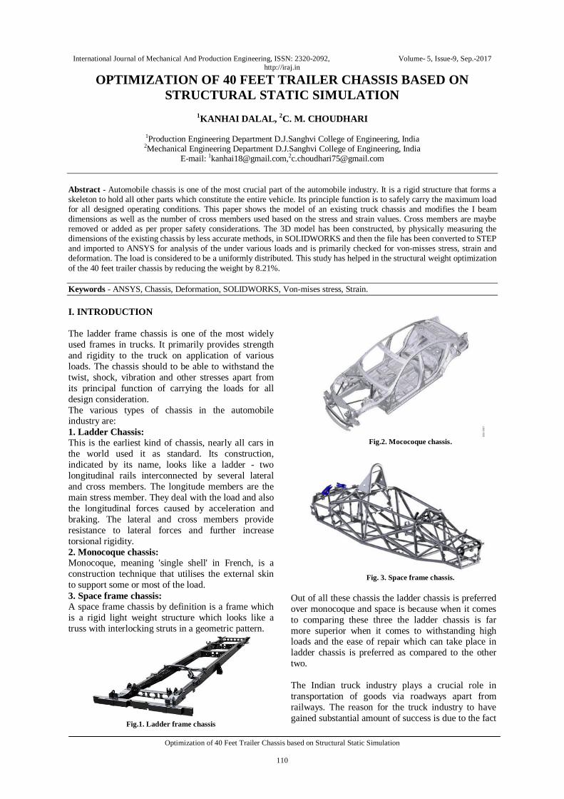
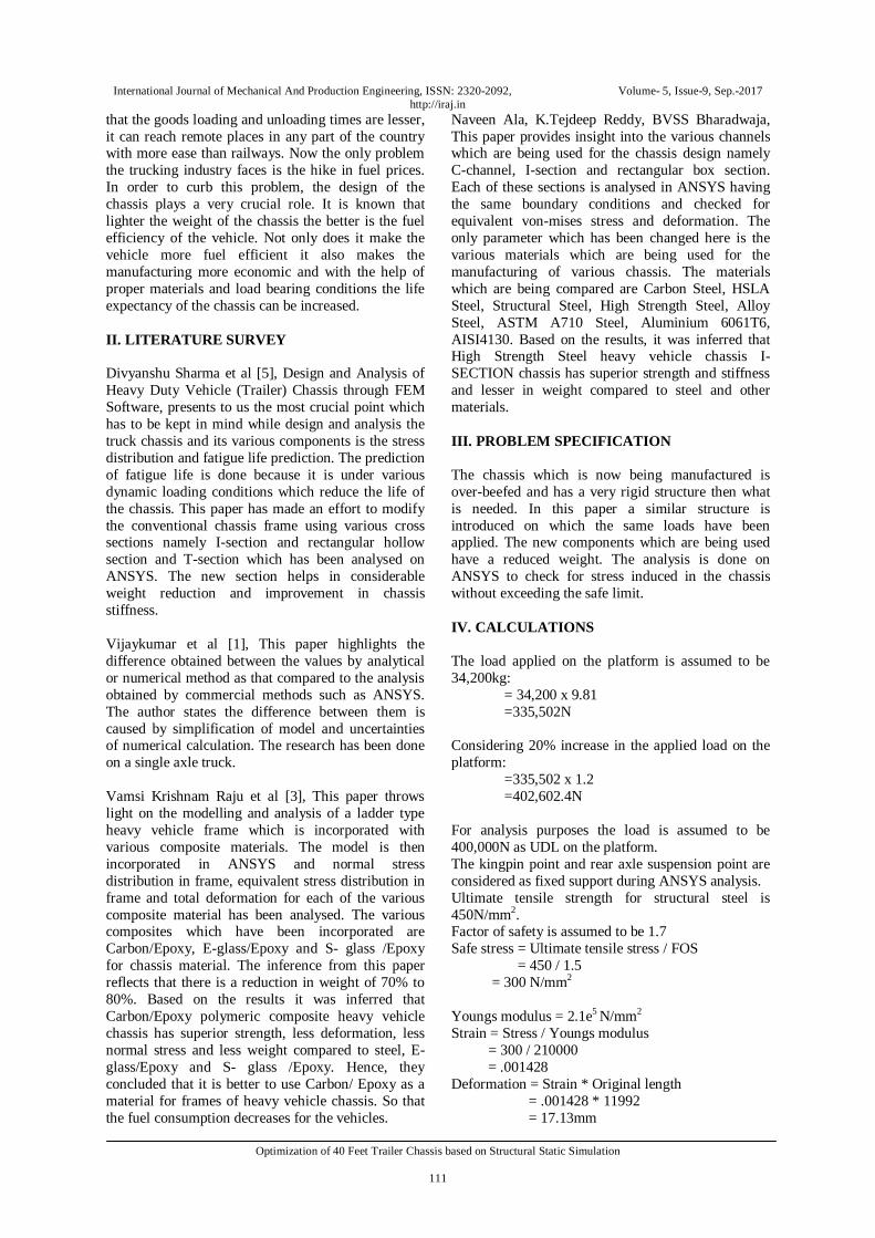
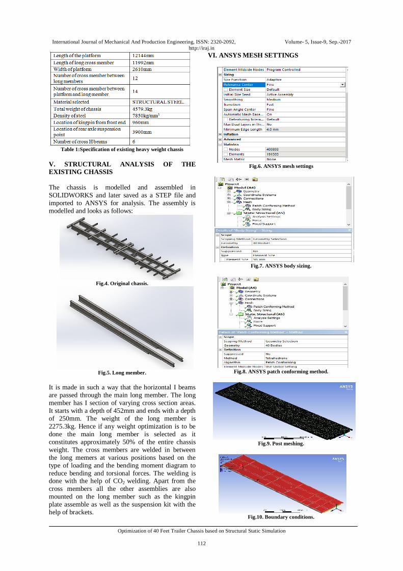
Abstract - Automobile chassis is one of the most crucial part of the automobile industry. It is a rigid structure that forms a skeleton to hold all other parts which constitute the entire vehicle. Its principle function is to safely carry the maximum load for all designed operating conditions. This paper shows the model of an existing truck chassis and modifies the I beam dimensions as well as the number of cross members used based on the stress and strain values. Cross members are maybe removed or added as per proper safety considerations. The 3D model has been constructed, by physically measuring the dimensions of the existing chassis by less accurate methods, in SOLIDWORKS and then the file has been converted to STEP and imported to ANSYS for analysis of the under various loads and is primarily checked for von-misses stress, strain and deformation. The load is considered to be a uniformly distributed. This study has helped in the structural weight optimization of the 40 feet trailer chassis by reducing the weight by 8.21%. Keywords - ANSYS, Chassis, Deformation, SOLIDWORKS, Von-mises stress, Strain. I. INTRODUCTION The ladder frame chassis is one of the most widely used frames in trucks. It primarily provides strength and rigidity to the truck on application of various loads. The chassis should to be able to withstand the twist, shock, vibration and other stresses apart from its principal function of carrying the loads for all design consideration. The various types of chassis in the automobile industry are: 1. Ladder Chassis: This is the earliest kind of chassis, nearly all cars in the world used it as standard. Its construction, indicated by its name, looks like a ladder - two longitudinal rails interconnected by several lateral and cross members. The longitude members are the main stress member. They deal with the load and also the longitudinal forces caused by acceleration and braking. The lateral and cross members provide resistance to lateral forces and further increase torsional rigidity. 2. Monocoque chassis: Monocoque, meaning 'single shell' in French, is a construction technique that utilises the external skin to support some or most of the load. 3. Space frame chassis: A space frame chassis by definition is a frame which is a rigid light weight structure which looks like a truss with interlocking struts in a geometric pattern.
Fig.1. Ladder frame chassis
Fig.2. Mococoque chassis.
Fig. 3. Space frame chassis.
Out of all these chassis the ladder chassis is preferred over monocoque and space is because when it comes to comparing these three the ladder chassis is far more superior when it comes to withstanding high loads and the ease of repair which can take place in ladder chassis is preferred as compared to the other two. The Indian truck industry plays a crucial role in transportation of goods via roadways apart from railways. The reason for the truck industry to have gained substantial amount of success is due to the fact
International Journal of Mechanical And Production Engineering, ISSN: 2320-2092, Volume- 5, Issue-9, Sep.-2017 http://iraj.in
Optimization of 40 Feet Trailer Chassis based on Structural Static Simulation
111
that the goods loading and unloading times are lesser, it can reach remote places in any part of the country with more ease than railways. Now the only problem the trucking industry faces is the hike in fuel prices. In order to curb this problem, the design of the chassis plays a very crucial role. It is known that lighter the weight of the chassis the better is the fuel efficiency of the vehicle. Not only does it make the vehicle more fuel efficient it also makes the manufacturing more economic and with the help of proper materials and load bearing conditions the life expectancy of the chassis can be increased. II. LITERATURE SURVEY Divyanshu Sharma et al [5], Design and Analysis of Heavy Duty Vehicle (Trailer) Chassis through FEM Software, presents to us the most crucial point which has to be kept in mind while design and analysis the truck chassis and its various components is the stress distribution and fatigue life prediction. The prediction of fatigue life is done because it is under various dynamic loading conditions which reduce the life of the chassis. This paper has made an effort to modify the conventional chassis frame using various cross sections namely I-section and rectangular hollow section and T-section which has been analysed on ANSYS. The new section helps in considerable weight reduction and improvement in chassis stiffness. Vijaykumar et al [1], This paper highlights the difference obtained between the values by analytical or numerical method as that compared to the analysis obtained by commercial methods such as ANSYS. The author states the difference between them is caused by simplification of model and uncertainties of numerical calculation. The research has been done on a single axle truck. Vamsi Krishnam Raju et al [3], This paper throws light on the modelling and analysis of a ladder type heavy vehicle frame which is incorporated with various composite materials. The model is then incorporated in ANSYS and normal stress distribution in frame, equivalent stress distribution in frame and total deformation for each of the various composite material has been analysed. The various composites which have been incorporated are Carbon/Epoxy, E-glass/Epoxy and S- glass /Epoxy for chassis material. The inference from this paper reflects that there is a reduction in weight of 70% to 80%. Based on the results it was inferred that Carbon/Epoxy polymeric composite heavy vehicle chassis has superior strength, less deformation, less normal stress and less weight compared to steel, E-glass/Epoxy and S- glass /Epoxy. Hence, they concluded that it is better to use Carbon/ Epoxy as a material for frames of heavy vehicle chassis. So that the fuel consumption decreases for the vehicles.
Naveen Ala, K.Tejdeep Reddy, BVSS Bharadwaja, This paper provides insight into the various channels which are being used for the chassis design namely C-channel, I-section and rectangular box section. Each of these sections is analysed in ANSYS having the same boundary conditions and checked for equivalent von-mises stress and deformation. The only parameter which has been changed here is the various materials which are being used for the manufacturing of various chassis. The materials which are being compared are Carbon Steel, HSLA Steel, Structural Steel, High Strength Steel, Alloy Steel, ASTM A710 Steel, Aluminium 6061T6, AISI4130. Based on the results, it was inferred that High Strength Steel heavy vehicle chassis I-SECTION chassis has superior strength and stiffness and lesser in weight compared to steel and other materials. III. PROBLEM SPECIFICATION The chassis which is now being manufactured is over-beefed and has a very rigid structure then what is needed. In this paper a similar structure is introduced on which the same loads have been applied. The new components which are being used have a reduced weight. The analysis is done on ANSYS to check for stress induced in the chassis without exceeding the safe limit. IV. CALCULATIONS The load applied on the platform is assumed to be 34,200kg:
= 34,200 x 9.81 =335,502N
Considering 20% increase in the applied load on the platform:
=335,502 x 1.2 =402,602.4N
For analysis purposes the load is assumed to be 400,000N as UDL on the platform. The kingpin point and rear axle suspension point are considered as fixed support during ANSYS analysis. Ultimate tensile strength for structural steel is 450N/mm2. Factor of safety is assumed to be 1.7 Safe stress = Ultimate tensile stress / FOS = 450 / 1.5 = 300 N/mm2
Youngs modulus = 2.1e5 N/mm2
Strain = Stress / Youngs modulus = 300 / 210000 = .001428 Deformation = Strain * Original length = .001428 * 11992 = 17.13mm
International Journal of Mechanical And Production Engineering, ISSN: 2320-2092, Volume- 5, Issue-9, Sep.-2017 http://iraj.in
Optimization of 40 Feet Trailer Chassis based on Structural Static Simulation
112
Table 1:Specification of existing heavy weight chassis
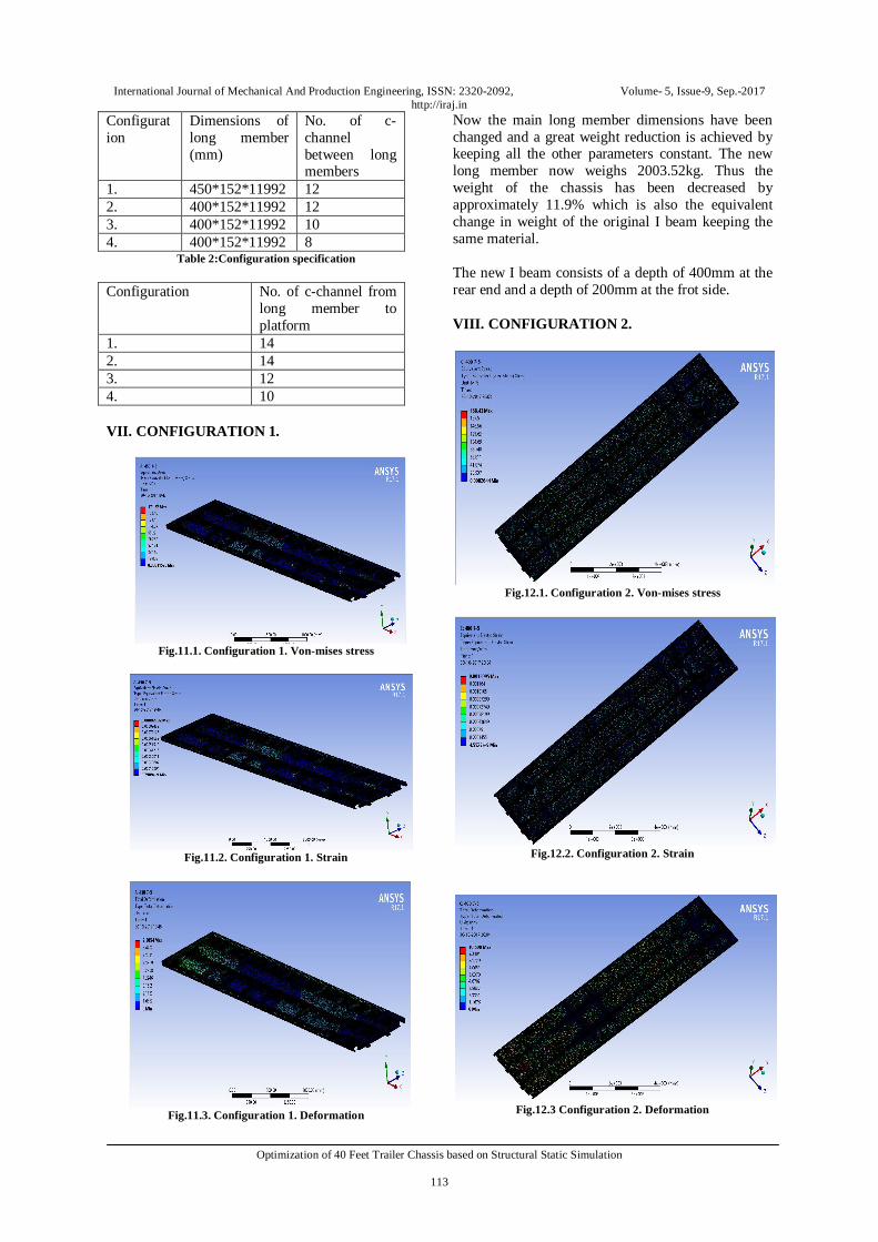
V. STRUCTURAL ANALYSIS OF THE EXISTING CHASSIS The chassis is modelled and assembled in SOLIDWORKS and later saved as a STEP file and imported to ANSYS for analysis. The assembly is modelled and looks as follows:
Fig.4. Original chassis.
Fig.5. Long member.
It is made in such a way that the horizontal I beams are passed through the main long member. The long member has I section of varying cross section areas. It starts with a depth of 452mm and ends with a depth of 250mm. The weight of the long member is 2275.3kg. Hence if any weight optimization is to be done the main long member is selected as it constitutes approximately 50% of the entire chassis weight. The cross members are welded in between the long memers at various positions based on the type of loading and the bending moment diagram to reduce bending and torsional forces. The welding is done with the help of CO2 welding. Apart from the cross members all the other assemblies are also mounted on the long member such as the kingpin plate assemble as well as the suspension kit with the help of brackets.
VI. ANSYS MESH SETTINGS
Fig.6. ANSYS mesh settings
Fig.7. ANSYS body sizing.
Fig.8. ANSYS patch conforming method.
Fig.9. Post meshing.
Fig.10. Boundary conditions.
International Journal of Mechanical And Production Engineering, ISSN: 2320-2092, Volume- 5, Issue-9, Sep.-2017 http://iraj.in
Optimization of 40 Feet Trailer Chassis based on Structural Static Simulation
113
Configuration
Dimensions of long member (mm)
No. of c-channel between long members
1. 450*152*11992 12 2. 400*152*11992 12 3. 400*152*11992 10 4. 400*152*11992 8
Table 2:Configuration specification Configuration No. of c-channel from
long member to platform
1. 14 2. 14 3. 12 4. 10 VII. CONFIGURATION 1.
Fig.11.1. Configuration 1. Von-mises stress
Fig.11.2. Configuration 1. Strain
Fig.11.3. Configuration 1. Deformation
Now the main long member dimensions have been changed and a great weight reduction is achieved by keeping all the other parameters constant. The new long member now weighs 2003.52kg. Thus the weight of the chassis has been decreased by approximately 11.9% which is also the equivalent change in weight of the original I beam keeping the same material. The new I beam consists of a depth of 400mm at the rear end and a depth of 200mm at the frot side. VIII. CONFIGURATION 2.
Fig.12.1. Configuration 2. Von-mises stress
Fig.12.2. Configuration 2. Strain
Fig.12.3 Configuration 2. Deformation

International Journal of Mechanical And Production Engineering, ISSN: 2320-2092, Volume- 5, Issue-9, Sep.-2017 http://iraj.in
Optimization of 40 Feet Trailer Chassis based on Structural Static Simulation
114
IX. CONFIGURATION 3.
Fig.13.1. Configuration 3. Von-mises stress
Fig.13.2. Configuration 3. Strain
Fig.13.3. Configuration 3. Deformation X. CONFIGURATION 4.
Fig. 14.1. Configuration 4. Von-mises stress
Fig. 14.2. Configiration 4. Strain
Fig 14.3. Configuration 4. Deformation
XI. RESULTS
Table 4: Stress, strain and deformationn for each of the
configuration considered
.Table 5: % weight saving for considered configurations CONCLUSION From the above results obtained it can inferred that the chassis which is being manufactured right now is over-beefed in nature and can be optimized for structural weight reduction without reducing the safety considerations. The above results provide a conclusion that a chassis with configuration 4 can be

International Journal of Mechanical And Production Engineering, ISSN: 2320-2092, Volume- 5, Issue-9, Sep.-2017 http://iraj.in
Optimization of 40 Feet Trailer Chassis based on Structural Static Simulation
115
used for the same purpose as the configuration 1 but there has been a weight saving og 8.21%. This change in weight also increases the overall fuel efficeincy of the entire vehicle. Thus the present chassis which is being manufactured can be replaced by a chassis having the same relative factor of safety but providing saving in cost through less usage of raw materials. This topic has a lot of future scope as the chassis can be modified not only by changing the dimensions of the various components but it can also be changed by varying the material. The chassis which is finalized can be then also checked under application of various heavy loads as well as vaious loading schemes in which there might be only point loads acting and also variable loads or a combination of both. REFERENCES [1] Vijaykumar V. Patel, "Structural analysis of a ladder chassis
frame," World Journal of Science and Technology 2012, 2(4)05-08.
[2] M. Ravi Chandra, S. Sreenivasulu and Syed Altaf Hussain, "Modeling And Structural Analysis of Heavy Vehicle Chassis Made of Polymeric Composite Material By Three Different Cross Sections", Journal of Mechanical and Production Engineering Research and Development (IJMPERD), ISSN 2249-6890, Vol.2, Issue 2, September 2012,45-60.
[3] V. Vamsi Krishnam Raju, B. Durga Prasad, M. Balaramakrishna and Y. Srinivas “Modeling and Structural Analysis of Ladder Type Heavy Vehicle Frame”, International Journal of Modern Engineering Research (IJMER).
[4] Monika S. Agrawal, “Finite Element Analysis of Truck Chassis Frame”, International Research Journal of Engineering and Technology (IRJET) e-ISSN: 2395-0056 Volume: 02 Issue: 03, June-2015.
[5] Divyanshu Sharma, Y D Vora, “Design and Analysis of Heavy Duty Vehicle (Trailer) Chassis through FEM Software”, International Journal of Engineering Technology, Management and Applied Sciences, April 2017, Volume 5, Issue 4, ISSN 2349-4476.
[6] Teo Han Fui, & Roslan Abd. Rahman, (2007), “Static and dynamic structural analysis of a 4.5 Ton truck chassis”, Journal mekanikal, 56-67.
[7] Hirak Patel, Khushbu C. Panchal, Chetan S. Jadav, “Structural Analysis of Truck Chassis Frame and Design Optimization for Weight Reduction”, International Journal of Engineering and Advanced Technology (IJEAT) ISSN: 2249 – 8958, Volume-2, Issue-4, April 2013.
[8] Rajput, R. K., Strength of Material, S. Chand & Company LTD.
[9] Anand Gosavi, Ashish Kumar Shrivastava, Ashish Kumar Sinha, “Structural Analysis of Six Axle Trailer Frame Design and Modification for Weight Reduction”, International Journal of Emerging Technology and Advanced Engineering, Volume 4, Issue 1, January 2014.
[10] R. L. PATEL, K. R.Gawande, D.B.Morabiya, “ Design and analysis of chassis frame of TATA 2516TC”, International journal for research in applied science and engineering technology (IJRASET), Vol. 2 Issue III, March 2014, ISSN: 2321-9653.
[11] Akash Singh Patel, Jaideep Chitransh, “Design and analysis of TATA 2518tc truck chassis frame with various cross sections using CAE tools”, International journal of engineering sciences & research technology, ISSN: 2277-9655.
[12] S. MURALI SANKAR, P. YUVARAJ, “Optimization of heavy truck chassis design parameters using fem”, International journal of pure and applied research in engineering and technology,ISSN: 2319-507X,Volume 3 (4): 333-343.