ir10-om00008 取扱説明書(ir1200-a 英文)
TRANSCRIPT

Document No. IR10-OM00008
PRODUCT NAME
Regulator
MODEL / Series / Product Number
IR1200-A IR1210-A IR1220-A

Contents
Safety Instructions 1 to 5
1. Application 6
2. Specifications 6
3. Construction and Operation Principles 7
4. How to order 8
5. Bracket, gauge and switch assembly (optional) 9
6. Panel mounting 10
7. Troubleshooting 11
8. Dimensions 12

Safety Instructions These safety instructions are intended to prevent hazardous situations and/or equipment damage. These instructions indicate the level of potential hazard with the labels of “Caution,” “Warning” or “Danger.”They are all important notes for safety and must be followed in addition to International Standards (ISO/IEC)*1) , and other safety regulations.
*1) ISO 4414: Pneumatic fluid power -- General rules relating to systems. ISO 4413: Hydraulic fluid power -- General rules relating to systems. IEC 60204-1: Safety of machinery -- Electrical equipment of machines .(Part 1: General requirements) ISO 10218-1992: Manipulating industrial robots -Safety. etc.
Caution Caution indicates a hazard with a low level of risk which, if not avoided, could result
in minor or moderate injury. Warning Warning indicates a hazard with a medium level of risk which, if not avoided, could
result in death or serious injury. Danger Danger indicates a hazard with a high level of risk which, if not avoided, will result
in death or serious injury.
Warning 1. The compatibility of the product is the responsibility of the person who designs the
equipment or decides its specifications. Since the product specified here is used under various operating conditions, its compatibility with specific equipment must be decided by the person who designs the equipment or decides its specifications based on necessary analysis and test results. The expected performance and safety assurance of the equipment will be the responsibility of the person who has determined its compatibility with the product. This person should also continuously review all specifications of the product referring to its latest catalog information, with a view to giving due consideration to any possibility of equipment failure when configuring the equipment.
2. Only personnel with appropriate training should operate machinery and equipment. The product specified here may become unsafe if handled incorrectly.The assembly, operation and maintenance of machines or equipment including our products must be performed by an operator who is appropriately trained and experienced.
3. Do not service or attempt to remove product and machinery/equipment until safety is confirmed.
1.The inspection and maintenance of machinery/equipment should only be performed after measures to prevent falling or runaway of the driven objects have been confirmed.
2.When the product is to be removed, confirm that the safety measures as mentioned above are implemented and the power from any appropriate source is cut, and read and understand the specific product precautions of all relevant products carefully.
3. Before machinery/equipment is restarted, take measures to prevent unexpected operation and malfunction. 4. Contact SMC beforehand and take special consideration of safety measures if the product is
to be used in any of the following conditions. 1. Conditions and environments outside of the given specifications, or use outdoors or in a place exposed to direct sunlight. 2. Installation on equipment in conjunction with atomic energy, railways, air navigation, space, shipping,
vehicles, military, medical treatment, combustion and recreation, or equipment in contact with food and beverages, emergency stop circuits, clutch and brake circuits in press applications, safety equipment or other applications unsuitable for the standard specifications described in the product catalog.
3. An application which could have negative effects on people, property, or animals requiring special safety analysis.
4.Use in an interlock circuit, which requires the provision of double interlock for possible failure by using a mechanical protective function, and periodical checks to confirm proper operation.
-1-
Safety Instructions
Caution 1.The product is provided for use in manufacturing industries.
The product herein described is basically provided for peaceful use in manufacturing industries. If considering using the product in other industries, consult SMC beforehand and exchange specifications or a contract if necessary. If anything is unclear, contact your nearest sales branch.
Limited warranty and Disclaimer/Compliance Requirements The product used is subject to the following “Limited warranty and Disclaimer” and “Compliance Requirements”. Read and accept them before using the product. Limited warranty and Disclaimer 1.The warranty period of the product is 1 year in service or 1.5 years after the product is
delivered, whichever is first. ****2) Also, the product may have specified durability, running distance or replacement parts. Please consult your nearest sales branch.
2.For any failure or damage reported within the warranty period which is clearly our
responsibility, a replacement product or necessary parts will be provided. This limited warranty applies only to our product independently, and not to any other damage
incurred due to the failure of the product. 3.Prior to using SMC products, please read and understand the warranty terms and disclaimers
noted in the specified catalog for the particular products. ****2) Vacuum pads are excluded from this 1 year warranty.
A vacuum pad is a consumable part, so it is warranted for a year after it is delivered. Also, even within the warranty period, the wear of a product due to the use of the vacuum pad or failure due to the deterioration of rubber material are not covered by the limited warranty.
Compliance Requirements 1. The use of SMC products with production equipment for the manufacture of weapons of
mass destruction(WMD) or any other weapon is strictly prohibited.
2. The exports of SMC products or technology from one country to another are govemed by the relevant security laws and regulation of the countries involved in the transaction. Prior to the shipment of a SMC product to another country, assure that all local rules goveming that export are known and followed.
-2-

①①①① Do not use in an atmosphere containing corrosive gases, chemicals, organic solvent, sea
water, water, water steam, or where there is direct contact with any of these. ②②②② Do not operate in environments subject to heavy vibration and/or impact. ③③③③ The regulator should not be exposed to prolonged sunlight. If used in direct sunlight, a
protective cover should be used. ④④④④ Do not install close to heat sources. If installed, protect the product against radiated heat from
source adequately. ⑤⑤⑤⑤ Install suitable protective measures in locations where there is contact with water drop- lets, oil
or welding spatter, etc.
①①①① Do not use a precision regulator outside of the range of its specifications as this can cause
failure. ②②②② Be sure to confirm the port indication when installing the product. ③③③③ When mounting the bracket or tightening the hexagon panel nut on the panel, tighten them to
the recommended tightening torque. Insufficient tightening torque can cause loose piping. Excessive tightening torque can cause thread damage.
Recommended tightening torque [N-m] Set nut (for bracket) 1.8 to 2.2 Hexagon panel net (handle type only) 3 to 4
④④④④ Adjust the pressure by increasing the pressure. After pressure adjustment, be sure to tighten
the lock nut. When tightening the nut, tighten so that the handle does not move due to friction caused by tightening. The outlet pressure may become lower than set pressure if adjusted by decreasing the pressure. Turning the handle clockwise increases the outlet pressure, and turning it counterclockwise reduces the pressure.
⑤⑤⑤⑤ When pressure is applied to the inlet of a regulator, make sure that the outlet port is connected to the circuit. Air blow occurs from the outlet and it depends on the operating conditions.
⑥⑥⑥⑥ The set pressure may vary depending on the elapsed time and change in ambient temperature after pressure setting. If the setting value varies, adjust with the handle.
⑦⑦⑦⑦ If the directional control valve (solenoid valve, mechanical valve etc.) is mounted and ON-OFF is repeated for a long time, the set pressure may vary. If the setting value varies, adjust with the handle.
⑧⑧⑧⑧ There may be pulsation or noise depending on the pressure conditions, piping conditions and ambient environment. In this case, it is possible to improve the problem by changing the pressure conditions and piping conditions.
If the problem is not improved, contact your SMC sales representative. ⑨⑨⑨⑨ There is no connection thread on the exhaust port. If it is necessary to mount a silencer to the
exhaust port, please contact your SMC sales representative. ⑩⑩⑩⑩ When a pressure gauge is mounted to the regulator, please do not exceed the maximum
display pressure. It may lead to a malfunction. ⑪⑪⑪⑪ A safety device needs to be installed if output pressure is exceeding the set pressure,
otherwise this can cause the breakage of outlet device and equipment or malfunction.
Operating Environment
Handling Precautions
Warning
CautionCautionCautionCaution
-3-

①①①① Connect piping/fittings using the recommended torque while holding the product tightly.
Looseness or faulty sealing will occur if tightening torque is insufficient, while thread damage will result if the torque is excessive. Furthermore, if the side with the female threads is not held while tightening, excessive force will be applied directly to piping brackets, etc. causing damage or other problems.
Recommended tightening torque [N-m] Thread 1/8 Torque 7 to 9
②②②② Do not apply any additional twisting, or bending moments except for the weight of the filter
regulator itself. Provide separate support for external piping, as damage may otherwise occur.
③③③③ Non-flexible piping materials such as steel piping will be subject to excessive moment load and vibration from the piping side, so use a flexible tube for intermediate connections.
①①①① Preparation before piping
Before piping is connected, it should be thoroughly blown out with air (flushing) or washed to remove chips, cutting oil and other debris from inside the pipe.
②②②② Wrapping of sealant tape When screwing piping or fittings into ports, ensure that metal chips from the pipe threads or sealing material do not enter the piping. Furthermore, when pipe tape is used, leave 1.5 to 2 thread ridges exposed at the end of the threads.
Piping
Warning
CautionCautionCautionCaution
-4-
①①①① When the precision regulator with pressure gauge is used, do not apply impact to the product
by dropping it etc. during transportation or installation. This may cause misalignment of the pressure gauge pointer.
①①①① The operating fluid must be compressed air. Contact SMC if using the product with other fluids. ②②②② Do not use compressed air that contains chemicals, synthetic oils including organic solvents,
salts or corrosive gases etc., as this can cause damage or malfunction. ③③③③ If condensate in the drain bowl is not emptied on a regular basis, the bowl will overflow and allow
the condensate to enter the outlet side. This will cause a malfunction of pneumatic equipment downstream of regulator. If the drain bowl is difficult to check and remove, installation of a drain bowl with an auto drain option is recommended.
①①①① Condensate or dust, etc. in the supply pressure line can cause malfunctions. Please use an air
filter (SMC series AF etc.) or mist separator (SMC AM, AFM series). Refer to “Air Preparation Equipment Model Selection Guide” (Best Pneumatics No. 5) for model selection based on air quality.
②②②② When a lubricator is used at the supply side of the product, it can cause malfunctions. Do not use a lubricator at the supply side of the product. If lubrication is required for terminal devices, connect a lubricator on the output side of the regulator.
①①①① When the product is removed for maintenance, reduce the set pressure to zero and shut off the
supply pressure completely beforehand. ②②②② When connecting an additional pressure gauge, the set pressure should be reduced to zero
before removing the plug. ③③③③ When using the regulator between a solenoid valve and an actuator, check the pressure gauge
periodically. Sudden pressure fluctuations may shorten the durability of the pressure gauge. A digital pressure gauge is recommended for such situation applications or as deemed necessary.
Air Supply
Maintenance
Handling
CautionCautionCautionCaution
CautionCautionCautionCaution
Warning
Warning
-5-
1. Application This instrument aims at controlling pressure of air lines.
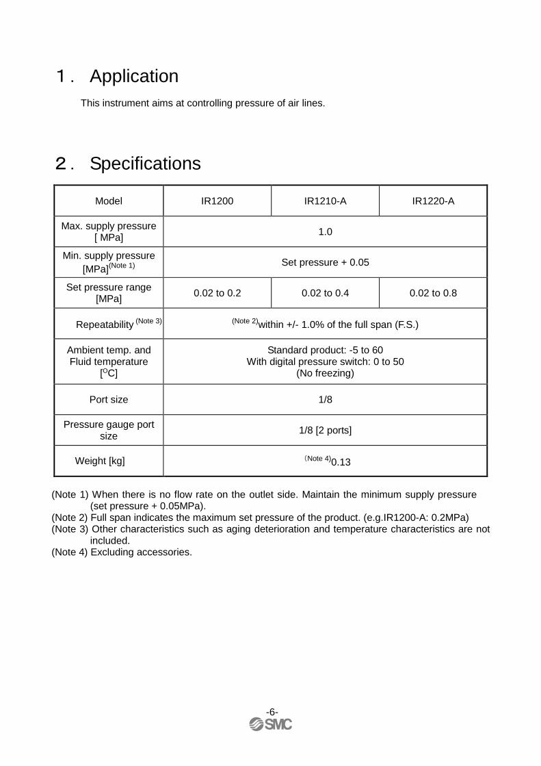
2. Specifications
Model IR1200 IR1210-A IR1220-A
Max. supply pressure [ MPa] 1.0
Min. supply pressure [MPa](Note 1)
Set pressure + 0.05
Set pressure range [MPa] 0.02 to 0.2 0.02 to 0.4 0.02 to 0.8
Repeatability (Note 3) (Note 2)within +/- 1.0% of the full span (F.S.)
Ambient temp. and Fluid temperature
[OC]
Standard product: -5 to 60 With digital pressure switch: 0 to 50
(No freezing)
Port size 1/8
Pressure gauge port size 1/8 [2 ports]
Weight [kg] (Note 4)0.13
(Note 1) When there is no flow rate on the outlet side. Maintain the minimum supply pressure
(set pressure + 0.05MPa). (Note 2) Full span indicates the maximum set pressure of the product. (e.g.IR1200-A: 0.2MPa) (Note 3) Other characteristics such as aging deterioration and temperature characteristics are not
included. (Note 4) Excluding accessories.
-6-

3. Construction and Operation Principles When the knob is rotated, the flapper is pushed through the spring, and a gap is generated between the nozzle and flapper. The supply pressure flows to the inlet passes through the path between the nozzle and flapper and acts on the supply diaphragm as nozzle pressure. The force generated by the diaphragm pushes down the valve, and the supply pressure flows to the outlet. The discharged air pressure acts on the exhaust diaphragm, and counteracts against the force generated by the supply diaphragm. The air pressure acts on the nozzle diaphragm at the same time, and counteracts against the compression force of the adjusting spring to adjust the set pressure. When the set pressure increases too much, the nozzle diaphragm is pushed up, and a gap is generated between the flapper and nozzle diaphragm. This happens after the flapper closes. The balance of the supply diaphragm and exhaust diaphragm is lost when the nozzle back pressure flows into the atmosphere. The exhaust valve is open after the valve is closed, and excess pressure on the outlet is released to the air. Due to this pilot mechanism, fine pressure variations are detected and precise pressure adjustment is possible.
Component parts No. Description Materials
① Bonnet Aluminum die-cast
② Nozzle diaphragm assembly Aluminum, Weather resistant NBR
③ Seal HNBR
④ Seal NBR
⑤ Diaphragm spacer Polyacetal
⑥ Supply diaphragm Weather resistant NBR
⑦ Exhaust diaphragm assembly Aluminum, Weather resistant NBR
⑧ Valve assembly Aluminum, stainless steel, HNBR
⑨ Body Aluminum die-cast
Grease: lithium grease
Adjusting spring knob
Nozzle diaphragm
Nozzle
Valve
⑥ Supply diaphragm Exhaust diaphragm
Flapper
①
②
⑨ ⑧
⑤
③
⑦
④ ④
Inlet (IN) Outlet (OUT)
IN / OUT side passage
-7-

4. How to order
-8-
Note1) Option are shipped together with the product, but not assembled. B and H cannot be select at the same time.
The current bracket cannot be used for this product.
Assembly of a bracket and set nuts.
Note2) See pressure unit table below.
Note3) For pipe thread type : NPT
Note4) For options : EA, EB, EC, ED
Note5) According to the new Measurement Law, only the SI unit type is provided for use in Japan.
Option/Semi-standard:Select one each for a to e.
Option/Semi-standard symble:When more than one
specification is required, indicate in alphanumeric
order.
Option N
ote1)
Sem
i-sta
ndard
G
ZA 注4)
Rc
With digital
pressure
switch
MPa
-
G
MPa MPa
Z 注3)
Nil
Rc
G - -
Only
overseasNPT
Only
overseasNPT psi psi
Rc - - -
Japan,
OverseasNPT Fixed SI unit
With unit
conversion function
(Initial value psi)
Pipe
thread
type
Name plate
in imperial units
pressure gauge in imperial unitsSales Note5)
G EA, EB, EC, ED
+
ePressure
unit Note2)
NilNilNilNil Name plate and pressure gauge in imperial unit : MPa
ZZZZ Name plate and pressure gauge in imperial unit : psi
ZAZAZAZA Digital pressure switch : With unit conversion function
RRRR Flow direction : Right to left
b
+
d KnobNilNilNilNil Upward
VVVV Downward
PNP open collector 1 output
ECECECEC NPN open collector 1 output + Analog voltage output
NPN open collector 1 output + Analog current output
+
cFlow
direction
NilNilNilNil Flow direction : Left to right
EDEDEDED
+
Pressure
gauge
NilNilNilNil Without pressure gauge
GGGG Round type pressure gauge
EAEAEAEA NPN open collector 1 output
EBEBEBEB
+
a Mounting
NilNilNilNil Without pressure gauge
BBBB With bracket
HHHH With hexagon panel nut (for panel mount)
NPT
FFFF G
+
Port size 01010101 1/8
Exhaust direction 0000 Bottom exhaust
+
Pipe thread type
NilNilNilNil Rc
NNNN
0.02~0.2MPa
1111 0.02~0.4MPa
2222 0.02~0.8MPa
+
-With unit
conversion function
・・・・
・・・・
Symble Description
Set pressure range
0000
IR 2 0 ― 01
1
BG ― ― A
3 4 5 62
0
1
2
3
4
5
6
1

5. Bracket, gauge and switch assembly (optional) 1.Bracket
1) Installation of bracket Mount the bracket to the regulator as shown on the picture. Assemble so that the regulator and rotation stopper of the bracket align properly.
2) Holding with the set nut Insert the set nut into the bonnet of the regulator so that the knurled tool face of the set nut will face the upper surface of the bracket. It is recommended that the set nut is tightened securely by hand.
* When retightening Please use hook spanner on hook groove of the set nut, and tighten. Please follow the table below for hand tightening and retightening.
Tool size [mm] Reference torque [N-m] 34/38 1.8 to 2.2
2. Round type pressure gauge, digital pressure switch
1) Instruction for mounting of the round type pressure gauge and digital pressure switch
Confirm that sealant is applied to the round type pressure gauge and digital pressure switch. Mount them into the chosen pressure gauge connection port. Please refer to "Piping" on page 5 when using sealant tape.
* Position adjustment of the round type pressure gauge
and digital pressure switch Adjust the round type pressure gauge by tightening the thread. Do not unscrew the gauge as air leakage may occur.
* Position adjustment of the pressure gauge and digital
pressure switch on the back of the regulator The pressure gauge connection port on the front of the regulator with round type pressure gauge and digital pressure switch is not plugged. When mounting the round type pressure gauge or digital pressure switch on the back of the regulator, please remove the plug on the back and mount it at the front.
Part name Tools Tool size [mm]
Recommended torque [N-m]
Plug Hexagon wrench key 4 0.55 to 0.65 Round type pressure gauge Wrench 10 7 to 9
Digital pressure switch Wrench 12 7 to 9
Set nut
Bracket
Regulator
(Upper surface of the bracket)
(Knurled tool face)
(Bonnet thread)
(Rotation stopper)
(Grooved)
Regulator
Plug
Round type pressure gauge
Digital pressure switch
(Front pressure gauge connection port)
(Rear pressure gauge connection port)
-9-

6.Panel mounting 1. Panel mounting
1) Handle removal Remove the handle from the regulator. 2) Panel mounting Insert the regulator into the panel. 3) Nut tightening
Adjust the regulator position and tighten the attached hexagon panel nut. Recommended tightening torque
Wrench size [mm] Tightening Torque[N-m] 14 3 to 4
4) Handle mounting
Mount the handle back onto the regulator.
* Excessive tightening of the handle may cause excessive pressure on the outlet side when supplying pressure.
* Recommended panel dimension
Panel hole diameter [mm] Panel thickness [mm] φ10.5 4 or less
Handle
Hexagon panel nut
Panel
Regulator
-10-

7.Troubleshooting No. Problem Possible causes Countermeasures
1 Reduction of the set pressure
Fluctuation of flow rate at the downstream side Set the pressure again. Return the flow rate at the downstream side to the initial rate.
Leakage due to deterioration of the rubber part.
Ozone Use the ozone resistant product (80- series). Temperature Avoid using at high temperature or low temperature. Organic solvent etc.
Take countermeasures to prevent organic solvent from the ambient atmosphere or fluid.
High frequency ON-OFF operation on the downstream side. Set the pressure again.
Pressure in the bonnet is reduced. Release the pressure in the bonnet which is the reference pressure to the atmosphere.
2 The set pressure increases or decreases as time passes. Aging deterioration of the regulator Set the pressure again.
3 Increased leakage from the bonnet breathing hole and exhaust port
Leakage due to deterioration of the rubber part.
Ozone Use the ozone resistant product (80- series). Temperature Avoid using at high temperature or low temperature. Organic solvent etc.
Take countermeasures to prevent organic solvent from the ambient atmosphere or fluid.
Foreign matter caught in the seat Install a filter or mist separator to clean the air supply.
Perform flushing by releasing the downstream side to atmosphere.
4 The set pressure changes periodically.
Supply pressure fluctuates. Install the regulator on the front to reduce the fluctuation. Ambient temperature and fluid temperature change Take countermeasures to prevent temperature changes.
5 Pressure does not increase. Insufficient min. supply pressure Increase the supply pressure.
6 Repeatability accuracy is bad. Due to problem 1. Refer to problem 1.
Due to problem 2. Refer to problem 2.
7 Oscillation occurs. Leakage from the downstream side. Prevent the leakage from the piping.
Downstream piping condition Oscillation occurs depending on the condition. In that case, please contact your SMC sales representative.
8
There is leakage from the ports other than the bonnet breathing hole and exhaust port.
Leakage due to deterioration of the rubber part. Consult SMC.
※ If any of the troubleshooting is not applicable, please contact your SMC sales representative.
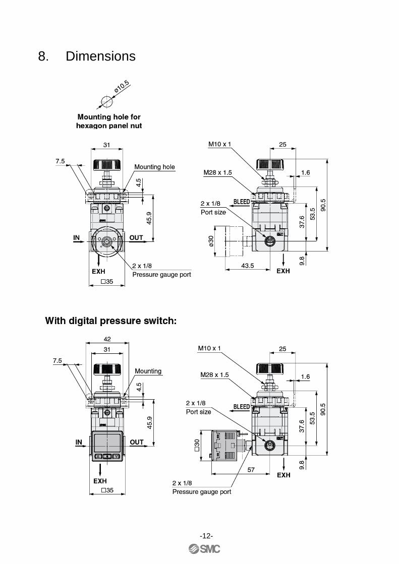
8. Dimensions
-12-

Revision history
4-14-1, Sotokanda, Chiyoda-ku, Tokyo 101-0021 JAPAN Tel: + 81 3 5207 8249 Fax: +81 3 5298 5362 URL http://www.smcworld.com Note: Specifications are subject to change without prior notice and any obligation on the part of the manufacturer. © 2011 SMC Corporation All Rights Reserved