ir barcode reader - cal poly
TRANSCRIPT

IR Barcode Reader
Neil Ivey 1.540.326.2617 [email protected]
Ben Eick 1.540.326.2617 [email protected]
Team WatchKeepers
Isaac Lambing [email protected]
Justin Gronet [email protected]
Tony Ly [email protected]
Mark Berry [email protected]

Statement of Disclaimer Since this project is a result of a class assignment, it has been graded and accepted as fulfillment of the course requirements. Acceptance does not imply technical accuracy or reliability. Any use of information in this report is done at the risk of the user. These risks may include catastrophic failure of the device or infringement of patent or copyright laws. California Polytechnic State University at San Luis Obispo and its staff cannot be held liable for any use or misuse of the project.
1

Table of Contents
List of Tables 3 List of Figures 4 Executive Summary 5 Chapter 1: Introduction 6
Project Management 6 Objectives/Specifications 8
Chapter 2: Background 12 Barcode Scanning 12 Taggant Technology 15 Patent Research 16 Batteries 17
Chapter 3: Design Development 18 Decision Matrices 19 Concepts 20
Chapter 4: Final Design 25 Description 25 Cost Analysis 27 Structural Analysis 30 Material Selection 32 Maintenance and Repair 32 Safety Consideration 32
Chapter 5: Product Realization 35 Manufacturing 35 Electrical Design 38 Program Design 41 Assembly 44
Chapter 6: Design Verification 47 Chapter 7: Conclusions and Recommendations 50
2

List of Tables
Table 1 : Major Deliverables Table 2: Engineering Project Requirements Table 3: Barcode Scanner Product Comparison Table 4. Patent Description Table 5. Component Specifications Table 6. Prototype Component Purchases. Table 7. Cal Poly Mechanical Engineering Department Prices. Table 8. Estimated Cost for Mass Production of Components. Table 9. Hazard Identification Safety Concerns Table 10: Safety Checklist Table 11. Raspberry Pi GPIO Pin Connections Table 12. Trigger, Reader, LCD, and Battery Pin Connections
3

List of Figures
Figure 1: Standard 12 Digit Barcode Figure 2, Left to Right: Quick Response (QR) Code, Data Matrix, Maxicode, Aztec Code Figure 3: Intermec SG20B 2D/1D barcode scanner Figure 4: Brainstorming including ideation for subsystems (left) and concept generation (right) Figure 5. Side by Side Model Figure 6. Side by Side Scan Engine Model Figure 7. Side by SIde Model Simplified Figure 8. iPhone Adapter Concept Model Figure 9. Heat Stake Concept Figure 10. Design Concept Figure 11: Prototype Scanner/Reader Device Model Figure 12. Device cut-away with components labeled. Figure 13. Oversized handle profile Figure 14. Current handle profile Figure 15: Trigger component eliminating pinch point Figure 16. Right side case part designed for injection molding. Figure 17. First Rapid Prototyping Iteration Figure 18. Second Rapid Prototyping Iteration Figure 19. Third Rapid Prototyping Iteration Figure 20. Breadboard layout of circuitry included within device. Figure 21. Inital State Diagram for BarcodeReaderScanner.py Figure 22. Assembly progress 1. Figure 23. Assembly progress 2. Figure 24. Assembly progress 3. Figure 25. Assembly progress 4. Figure 26. Complete Assembly progress 5. Figure 27. Initial battery test monitoring voltage as battery discharged Figure 28. Theoretical Li-Ion Voltage Curve for 190-1800 mAh
4

Executive Summary BrandWatch Technologies is a company based in Portland, Oregon that seek to detect counterfeit products in the supply chain. BrandWatch has created a taggant material, a physical marker, that can be printed over barcodes or added to the ink used to print the barcodes themselves. This material, while invisible to the naked eye, is detectable using technology that they have developed. BrandWatch enlisted the help of a four man team of Cal Poly Mechanical Engineering students to combine this technology with that of a barcode scanner. The device, capable of scanning barcodes, detecting the presence of the taggant material, and relaying this information to the user is the end result of this project. The device is easily modifiable to request a taggant read or barcode scan first. A user simply has to pull the trigger and is walked through the process of scanning and reading via LCD screen prompts on the back of the handheld device. The data collected (both barcode and the presence of the taggant) is stored in a csv file on a small USB drive on the back of the device. This can easily be removed to transfer the data to a computer at the end of a work day.
5

Chapter 1: Introduction The presence of fraudulent products in the supply chain can cripple companies otherwise producing legitimate goods. The introduction of excess supply drives the market price down and stains the name of the company when users purchase illegitimate products of lesser quality. BrandWatch Technologies has developed a solution to this issue by incorporating a taggant, a physical marker invisible to the naked eye, into product barcodes. BrandWatch Technologies has developed a device to detect the presence of this taggant material. Many of their customers have requested a device that can test for this taggant and scan barcodes simultaneously to help increase their productivity. The broad customer base ranges from high school educated blue collar workers to quality engineers verifying authenticity. Team “WatchKeepers” consists of four Cal Poly Seniors who will be working with BrandWatch Technologies to prototype a consumer electronic device that integrates taggant reading and barcode scanning technologies. The four seniors are Mark Berry, Justin Gronet, Isaac Lambing, and Tony Ly. All members are working towards a Mechanical Engineering BS. Project Management The responsibilities pertaining to this project are divided into different disciplines. This ensured the project as a whole was completed and nothing was left out or missed. All of the responsibilities were assigned based on the team member’s background knowledge on the discipline. Below is the list of responsibilities each team member had: Mark Berry
Information gathering Sponsor communication Documentation of Project Process
Justin Gronet Software Lead Electrical Lead
Isaac Lambing Manufacturing Lead
Tony Ly Hardware Lead
6

Management Plan Table 1 below outlines the major deliverables throughout the duration of the project.
Table 1 : Major Deliverables
Date Milestone
10/23/14 Project Proposal
11/14/14 Preliminary Design Report
11/6/14 Preliminary Design Review
1/13/15 Final Design Report
2/3/15 Final Design Report
2/5/15 Critical Design Review
2/19/15 Electrical Testing Results
2/26/15 3-D Print Case
3/3/15 Prototype Assembly
3/17/15 Hardware Testing Results
4/1/15 Software Testing Results
4/10/15 Project Update Memo
5/1/15 System Testing Results
5/29/15 Senior Design Expo
6/8/15 Final Project Report
7

Objectives/Specifications Many counterfeit products are introduced into legitimate supply chains through the replication of easy to mimic bar codes. BrandWatch Technologies has developed a taggant material that can be added to a product to provide another layer of verification for authentic goods. An easy to use scanner that can read barcodes and is also able to identify the presence of this taggant material is needed. The primary objective for this project is to design, build, and test a prototype device that incorporates barcode scanning and taggant reading technologies. The secondary objective (dependant on time allotted) is to design a device that provides taggant reading functionality as an add-on to high-end scanners on the market. The customer requirements are as follows:
Capability to scan both 1D and 2D barcodes Device should have multiple modes to prevent scanning until taggant is detected and
vise versa Barcodes should either be stored on the device or immediately transferred to be stored
elsewhere (on a computer in most cases) Some sort of notification should happen so that the user understands the outcome of the
scanner and reader (LEDs, audio feedback, LCD screen, etc.) The product should have a reasonable battery life The device shall be portable, ergonomic, and intuitive to use The product shall be resilient over its lifetime when subject to normal usage The prototype should be representative of something that can later be manufactured in
larger quantities The product should be competitively priced It should be difficult to bypass taggant reader - tamper resistant
The customer requirements outlined above are a result of direct communication with BrandWatch Technologies and an understanding of their customers. Engineering specifications are derived from these customer requirements to give the requirements quantitative value. Each specification is then analyzed using a pairwise comparison method to determine their relative weight (or importance). This method compares two requirements at a time to determine their weighted average when compared to all of the specifications as a whole. This information is then utilized in a quality function deployment (QFD) which can be found in Appendix A. Engineering specifications are compared to customer requirements. Intersecting cells in the QFD are given a number 0 (blank) through 9 that shows the strength of the relationship between that particular requirement and specification. The QFD ultimately takes the strength of the relationships and weight determined by the pairwise comparison to determine the risk or importance of each engineering specification.
8

The LCD screen provides a good example that demonstrates how the QFD functions. The LCD screen has a large impact on other requirements (battery life, drop performance, price, etc) but very low relative importance when compared to other features. The QFD takes both of these into account when determining the low weighted importance of the LCD screen requirement. The engineering specifications are listed in Table 2 in descending order of risk as determined by the QFD.
9
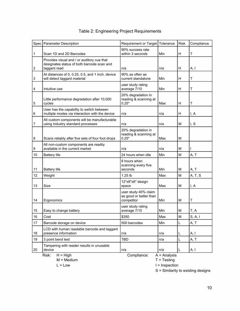
Table 2: Engineering Project Requirements
Spec Parameter Description Requirement or Target Tolerance Risk Compliance
1 Scan 1D and 2D Barcodes 90% success rate within 3 seconds Min H T
2
Provides visual and / or auditory cue that designates status of both barcode scan and taggant read n/a n/a H A, I
3 At distances of 0, 0.25, 0.5, and 1 inch, device will detect taggant material
90% as often as current standalone Min H T
4 Intuitive use user study rating average 7/10 Min H T
5 Little performance degradation after 10,000 cycles
20% degradation in reading & scanning at 0.25" Max H T
6 User has the capability to switch between multiple modes via interaction with the device n/a n/a H I, A
7 All custom components will be manufacturable using industry standard processes n/a n/a M I, S
8 Scans reliably after five sets of four foot drops
20% degradation in reading & scanning at 0.25" Max M
9 All non-custom components are readily available in the current market n/a n/a M I
10 Battery life 24 hours when idle Min M A, T
11 Battery life
8 hours when scanning every five seconds Min M A, T
12 Weight 1.25 lb Max M A, T, S
13 Size 12"x8"x6" design space Max M I, A
14 Ergonomics
user study 40% claim as good or better than competitor Min M T
15 Easy to change battery user study rating average 7/10 Min M T, A
16 Cost $350 Max M S, A, I
17 Barcode storage on device 500 barcodes Min L A, T
18 LCD with human readable barcode and taggant presence information n/a n/a L A, I
19 3 point bend test TBD n/a L A, T
20 Tampering with reader results in unusable device n/a n/a L A, I
Risk: H = High Compliance: A = Analysis M = Medium T = Testing L = Low I = Inspection
S = Similarity to existing designs
10

Details of each requirement is provided below: 1. Scanning both 1D and 2D barcodes allows this device to be as versatile as possible. 2D barcodes
are typically scanned using an optical method as opposed to a reciprocating laser that is common in 1D only barcode scanners.
2. Typical users and their use cases will vary widely, which requires easy switching between multiple usage modes. For example, a worker may be interested in blocking the barcode scanning technology until the presence of the taggant has been confirmed when checking in inventory, but want to halt the taggant reading until the barcode has been scanned when a customer is curious about the price of a particular item.
3. The core technology of this device is the taggant detector which has already been built and proven in large quantities. Because of this, the implementation of this technology should provide little to no impact on it’s performance.
4. A portion of typical users will only have acquired a high school diploma requiring a device that is straightforward in it’s usage.
5. The product shall perform reliably over it’s lifetime as it will eventually ideally be in the hands of many consumers.
6. A cue to the user can come in many forms. In it’s simplest, it may be a set of two LEDs that flash either green or red depending on a successful or unsuccessful reading or scanning. The device may include a speaker which would provide certain tones depending on the outcome of the barcode interrogation.
7. For example, if plastic parts are required, injection molding guidelines will be followed. 8. Since the device will be carried, drop performance is critical. While certain factors cannot be
ignored (the strength of rapid prototyped plastic is a fraction of injection molded plastic for example) This requirement will insure a robust design.
9. Commercial off the shelf components will be important in allowing the product to be produced in larger quantities.
10. Battery life in its idle state is important for usages when large spans of time take place between scans.
11. Ideally the product can still perform for a full eight hour work day when scanning at a high frequency representative of heavy use.
12. As the product will be carried, a low weight is necessary. 13. A small form factor is critical in the devices portability. 14. Customers will gravitate away from a product that is uncomfortable to handle. 15. Since batteries will most likely be changed fairly frequently, it is important to make this process as
painless as possible for the end user 16. The price requirement is ranked relatively low. This is because we would like to provide as many
features as possible in this prototype. This will allow BrandWatch Technologies to have a more analytical approach to choosing which functionalities to keep in the final product.
17. To help its portability, the product should be able to store barcodes on the device that can later be transferred to a computer.
18. An LCD could potentially be used to provide the output of the barcode in human readable format directly on the device itself.
19. A three point bend test will represent a failure mode in which the device is resting on a table and a heavy object is accidentally placed on top of it, or if the front edge of the device impacts a surface while it is being held.
20. The taggant reader is critical in detection of counterfeit products and should not be bypassed.
11

Chapter 2: Background The background research for this project is divided between the two main technologies: Barcode scanning and Taggant reading. Information will be included on barcode types and scanning methods, as well as taggant properties and reading methods. Additional information is included on how these systems can be integrated.
Barcode Scanning Barcode scanners on the market provide a very diverse range of features. Low-end scanners with relatively limited capabilities are limited to scanning 1-D or 2-D barcodes, while high-end scanners have a vast range of capabilities due to their integrated operating system that can upload barcode information to servers and provide relevant information to the user. Each 1-D barcode consists of a series of black lines with white bars in between. The first three bars, black-white-black, are used to set a standard unit of thickness. All of the bars following these will have thickness proportional to 1, 2, 3, or 4 times this initial bar thickness. Each set of 4 bars is used to encode a single digit number (for example, ‘1’ is encoded in a series of bars 2, 2, 2, and 1 unit thick). Most 1-D barcodes contain 12 digits total (see Figure 1). The first 6 digits are assigned to various manufacturers by the Uniform Code Council (UCC), which collects fees for the use of these codes. The next five digits are chosen by the manufacturer to identify the specific product. The last digit is calculated by an algorithm, and is used to ensure that the barcode scanner has correctly interpreted the other 11 digits. Note that some barcodes contain zero-suppressed numbers, in which sets of 4 zeros (which do not need to be consecutive) are removed from the code. Unlike 1-D barcodes, 2-D barcodes (see Figure 2) can store information vertically and horizontally. They can carry much more information: Quick Response (QR) codes can carry about 4,000 characters or 7,000 digits. 2-D barcodes vary more than 1-D codes. Common types of 2-D barcodes include common QR codes, Maxicode used by UPS, and Data Matrix used by the US Department of Defense (Sentell, 2014).
Figure 1. Standard 12 Digit Barcode Barcode scanners employ several methods to scan barcodes, including lasers, CCD sensors, and cameras. Most barcode scanners use lasers to sense the differences in thickness and color (white-black) of the bars. Some scanners use a single laser, which is moved across the code at
12
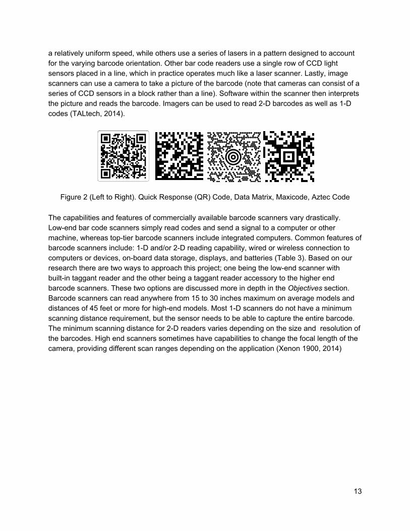
a relatively uniform speed, while others use a series of lasers in a pattern designed to account for the varying barcode orientation. Other bar code readers use a single row of CCD light sensors placed in a line, which in practice operates much like a laser scanner. Lastly, image scanners can use a camera to take a picture of the barcode (note that cameras can consist of a series of CCD sensors in a block rather than a line). Software within the scanner then interprets the picture and reads the barcode. Imagers can be used to read 2-D barcodes as well as 1-D codes (TALtech, 2014).
Figure 2 (Left to Right). Quick Response (QR) Code, Data Matrix, Maxicode, Aztec Code The capabilities and features of commercially available barcode scanners vary drastically. Low-end bar code scanners simply read codes and send a signal to a computer or other machine, whereas top-tier barcode scanners include integrated computers. Common features of barcode scanners include: 1-D and/or 2-D reading capability, wired or wireless connection to computers or devices, on-board data storage, displays, and batteries (Table 3). Based on our research there are two ways to approach this project; one being the low-end scanner with built-in taggant reader and the other being a taggant reader accessory to the higher end barcode scanners. These two options are discussed more in depth in the Objectives section. Barcode scanners can read anywhere from 15 to 30 inches maximum on average models and distances of 45 feet or more for high-end models. Most 1-D scanners do not have a minimum scanning distance requirement, but the sensor needs to be able to capture the entire barcode. The minimum scanning distance for 2-D readers varies depending on the size and resolution of the barcodes. High end scanners sometimes have capabilities to change the focal length of the camera, providing different scan ranges depending on the application (Xenon 1900, 2014)
13

Table 3: Barcode Scanner Product Comparison
Product Code Capability
Minimum Scan
Distance
Maximum Scan
Distance
Wired/ Wireless
Battery Life Range Price
Wasp WCS 3905
1-D - 1" Wired N/A N/A $87.22
Motorola Symbol LS 2208
1-D 0-2.5" 6-30" Wired N/A N/A $109.56
Motorola CS3070
1-D 1" 45' Either 12-24 Hours, 4K- 8K Scans
30 ft. $239.99
Datalogic GD4430-
BK GD4430
1-D, 2-D 0.2-1.6" 4.9-15.7" Wired N/A N/A $230.99
Intermec SG20B
1-D, 2-D .004-.007"
4-26" Wireless 8K Scans 33 ft. $371.57
Socket Mobile
CHS 7Xi
1-D, 2-D - - Wireless 10 Hours, 1000 Scans
330 ft. $484.13
Honeywell Xenon 1902
1-D, 2-D 0-4.2" 3-22.1" Wireless 14 Hours, 50K scans
33 ft. $536.70
Intermec SR61
1-D, 2-D 1.7-4.4" 5.4-15.6" Wired N/A 100 ft. $524.27
*Scan distance varies depending on the type of barcode being scanned. Minimum and maximum values are reported.
14

Figure 3: Intermec SG20B 2D/1D barcode scanner
1D and 2D scanning technology, while normally delivered as part of a package that is directly consumed by an end user, is also offered as a basic device that can then be implemented into a larger system, known as a ‘scan engine’. Intermec is one company that makes these devices (EA11 Standard-Range 2D Imager, 2014). Intermec has a long standing history of barcodes, having developed a code (CODE-39) which is used as the standard for U.S. industrial applications (Burke, 2014). These scan engines include a camera, LEDs, and dedicated hardware for deciphering barcodes in a package with mounting options. Alternatively, a simple image sensor or camera can be used along with a microcontroller running an open source barcode scanning technology like zbar to interpret a barcode (Brown, 2014). A five megapixel camera has been developed that integrates seamlessly with the Raspberry Pi (Camera Module Setup, 2014). This hardware integration can provide high framerates (Jones, 2014) which, while slower than that of a dedicated hardware setup like a scan engine, may be sufficient for the application. Regardless, a microcontroller can ultimately provide a means to integrate barcode scanning and taggant reading technologies. Popular microcontrollers like Raspberry Pi and Arduino can also serve to store barcodes and interface with LCDs, LEDs, speakers, etc (Raspberry Pi, Arduino, 2014). The Raspberry Pi in particular has capabilities to connect to the internet with a simple usb dongle that could allow it to update a cloud based document.
Taggant Technology The fundamental technology behind our project is the taggant that is included in barcodes of genuine products. This taggant is a physical/chemical marker that can be used in multiple applications, however for our project we will be focusing on the product barcode application. Including this taggant in barcodes offers a covert solution to counterfeit products. BrandWatch Technologies has already developed the technology to test for taggant through Infrared reading. The infrared wavelengths excites electrons in the taggant, pushing them to a higher valence band. When they fall back down to their stable band, they emit energy that can be detected by
15

an infrared photodiode. This BrandWatch technology is being released to us for use in our design. Further development of a taggant reader is not in the scope of our project. An issue that needs to be considered is the distance that the reader will recognize the taggant. The amount of taggant used is inversely proportional to how close the reader must be to confirm the presence of the taggant. For testing purposes we will assume 0.5 in. is an adequate distance, 0.25 in. is a good distance and ideally the user will be in contact with the barcode when trying to read for the taggant (BrandWatch Technologies). These distances are quoted from BrandWatch Technologies and subject to change after testing.
Patent Research The initial patent search by our team focused on three patents for barcode scanning devices that related. The technology for scanning 1-D and 2-D barcodes are abundant and relatively cheap depending on the quality of scanner. Therefore, from a design standpoint the focus will be geared more towards the taggant reader and the integration of the reader and scanner. Description of the three patents that were used as research are listed in Table 4.
Table 4. Patent Description
Patent Name Patent number Relative component Description
Method for Remote Detection of Volatile Taggant US6025200 Taggant Reader
Process of application and detection of taggant
Taggant particle group, anti-counterfeit ink comprising same, anti-counterfeit toner, anti-counterfeit sheet, and anti-counterfeit medium EP2650141A1 Taggant Reader
Applications for taggant detection
Multi-level anti-counterfeit, security and detection taggant US20100050901 Taggant Reader
Incorporates multiple degrees of taggant security through more sophisticated applications of taggant
Multiple ways of using taggant for anti-conterfeiting purposes do exist. The idea of a more sophisticated anti-counterfeit technique with taggant is attractive to multiple industries including military applications. Current techniques for authenticity verification include holograms and watermarks requiring visual inspection. While these have their benefits, improved techniques will not only reduce counterfeit products in the market but also increase speed that verification is performed. Patents for anti-counterfeiting using taggants also include using taggant to create symbols that adds yet another level of advanced authentication from sophisticated counterfeit products. Design considerations for taggant symbol reading in addition to taggant detection will be taken into account (Yamauchi).
16

Patents for taggant detection devices were nonexistent from the research done, however BrandWatch Technologies has devices that perform this function required. In conclusion, this patent search provided our team the assurance that the supporting technology for an integrated barcode scanner/ taggant reader is in need. Our patent research has verified that this design project will not infringe on other’s intellectual property. Batteries A variety of different options come into play when considering batteries. The most intuitive option is a rechargeable battery. Today most electronics with similar applications use a Lithium-ion battery because of its high energy density.Other less popular batteries include lithium-polymer and nickel-cadmium, both of which don’t offer the size and power capabilities of the lithium-ion and are out of date. The drawbacks to lithium-ion batteries are their expensive nature and notoriously unsafe history. In order to ensure safety, an off-the-shelf lithium-ion battery with built-in recharge circuitry is the most appealing option. Another power option to keep in mind are disposable batteries. One foreseen issue is the significant power draw of the device that could make replacing the batteries expensive and inconvenient for the user. Power draw calculations will result in a better understanding of whether or not disposable batteries are a viable option. Finally, the last option that should be considered is an AC powered solution. This prevents mobility, however should still be considered for certain applications.
17

Chapter 3: Design Development We utilized a structured design process to assist our group in the development of the design. After the problem had been defined and specifications developed, necessary subsystems and the integration of those subsystems were thought out through the design process below. The main subsystems that were conceptualized include: relay of information, device trigger, and mode switching. Within each subsystem, ideas were compared to each other by determining their relationship to the engineering specifications. Ultimately, the solutions that came from our design development tools were incorporated into our final design. The following tools are listed in order of the development process. Brainwriting Our initial ideation technique was brainwriting within our team for each of the 7 functions our project was required to do. With brainwriting each member thinks of as many ways to achieve the function as possible to themselves and after 2 minutes each member exchanges papers with another member in your group, observe what they wrote down and continue to develop ideas without communicating with one another. By doing this, no judgements on specific ideas are made and the maximum possible solutions are thought of. At the end of our brainwriting session we had about twenty ideas per person.
Brainstorming Proceeding brainwriting were multiple brainstorming session, which follows similar guidelines as brainwriting, however group members are permitted to communicate with each other. This was done for each function and many of the ideas that originated in brainwriting carried over and were discussed, altered and added onto. Once we had maximized the number of ideas, we turned to “Controlled Convergence” to narrow down these ideas to multiple concepts.
Figure 4: Brainstorming including ideation for subsystems (left) and concept generation (right)
18

Go/No-Go A large portion of our ideas did not comply with determined specifications and thus were removed from our consideration. Most of these ideas that were eliminated in the Go/No-Go stage were impractical and fell well outside the scope of our project Decision Matrices To better narrow down the concepts, specifications were compared to concepts with Pugh matrices. Pugh Matrices are a decision making tool used to rank different features of a product through a quantitative analysis. Each Pugh matrix had a datum in which all concepts were compared to per specification. The three functions we needed assistance with determining a solution for were relaying information, triggering the device and switching between modes. The results from the Pugh Matrices contradicted our group intuition and sponsor’s input, therefore our team decided to create Decision Matrices (Appendix B) to organize the possible solutions. From our Pugh Matrices, we increased the scale which we compare each concept to one another, from -1, 0 and +1 to -3 through +3. This made a large impact in concepts that offer significant advantages such as an LCD screen. Our team researched each possible solution and rated the following components in Appendix B.
Table 5. Component Specifications
Price($)
Power input( W) Weight(g) Size(mm) Link
LED (4) 2.00 0.15 N/A 6x6x9 https://www.adafruit.com/product/159
Speaker 0.95 0.042 4.3 42x42x6 http://www.adafruit.com/products/1739
LCD 9.95 0.6 N/A 34x80x14 http://www.adafruit.com/datasheets/TC1
602A-01T.pdf
Haptics 1.95 0.5 0.9 10x10x3 http://www.adafruit.com/products/1201
Alarm Clock
Display 3.95 0.5 8.3 50x19x8 http://www.adafruit.com/products/865
Projector 8.95 0.125 11.9 10x10x33 http://www.adafruit.com/products/1058
Distance Sensor 14.06 0.125 2.0 44x13x13.5
https://www.sparkfun.com/products/8959
The last change we made in our matrices was the weight of each specification. In the Pugh matrices the specification weight was based off of the system, whereas our more defined Decision matrices have weights that are based off their respective function.
19

Concepts Side by Side Model The Side by Side model uses a Raspberry Pi to scan (with the help of an integrated camera) and process data from the taggant reader. The camera and the existing taggant-detecting board will sit side by side at the front of the device, which resembles a typical 2D barcode scanner. The device is powered by a battery in it’s handle and stores barcode data on the Pi. The barcode data can be displayed on the LCD screen, and transferred to a computer via a USB drive or through the cloud, as long as the device is within range of a wireless network. In all of the side by side models, the taggant reader will be physically separated from the other components to eliminate any interference in the reading due to light leakage.
Figure 5. Side by Side Model
Side by Side Scan Engine Model Similar to the Side by Side model, this device will take the shape of a typical 2D barcode scanner. The only difference is that it will utilize a scan engine instead of a standalone camera.
Figure 6. Side by Side Scan Engine Model
20

Side by Side Model Simplified This model utilizes the main structure of the side by side model but removes everything but the bare bones components required to function. A smaller microcontroller can be used, and the relay of information is accomplished using two LEDs.
Figure 7. Side by SIde Model Simplified
21

iPhone Adapter Model This model will use an iPhone for the brains of the device. A backpack type device will attach to the iphone with a cable that mates with the port on the bottom of the phone. The backpack will have a simple mirror that redirects the field of view of the camera so that it can take pictures of the barcode while the phone is held perpendicular to the surface it is on. The backpack will also contain the taggant reader. All of the barcode decoding and interaction between taggant and barcode will be done in software on an app on the phone.
Figure 8. iPhone Adapter Concept Model
Lead Concept Model - Side by Side Model Figure 10 models the decision of our design based on the outcome of our decision matrices. The model does not show details on material or a finalized layout for the geometry. However, the case will be designed to be manufactured via injection molding. In this model, Watchkeepers planned to heat stake the boards into the case to prevent tampering with the communication between the taggant reader and the microcontroller (see Figure 9 for a visual depiction of the heat staking method). Both boards would be mounted in a manner that prevents the removal of the cable between them unless the boards themselves are removed.
22

Figure 9. Heat Stake Concept
The trigger will be an injection molded piece that will snap into the main body of the device and interface with a switch immediately behind it. This design has not been fully developed but has been found in existing competitor’s models. The position and mounting of the other small components (such as the speaker, LEDs, mode switcher, etc) are not finalized and will be decided upon as the project progresses. Details of the undecided portions mentioned above will be described in detail in the critical design report. The device will obtain data using a two step process. When the trigger is pulled, the Raspberry Pi will activate either the taggant reader or barcode scanner, depending on the mode. After this task has been completed (taggant deemed present or barcode decoded) the Raspberry Pi will trigger the other device automatically. While only requiring one trigger pull by the user, the device will have to be manually moved towards / away from the barcode to be within the ranges of the reader and scanner respectively. As development continued and preliminary testing was done, this initial concept model was revised and is shown in the Prototype section. The main change implemented was switching from a camera based system to a scan engine for the barcode decoding portion of the design. This was due to preliminary testing of the camera system which demonstrated that the system was not capable of the speed necessary for the design to be on par with current off the shelf systems. The scan engine reviews and explanation from the company CODE Corp. showed more promise in speed of scan compared to a third party open source program that runs off the Raspberry Pi camera. The decision to go with the Raspberry Pi as the computer for our device was for prototyping capabilities. The Pi was inexpensive while still being capable to run any open-source software. The was an ideal choice due to the complexity of programming and the engineers programming capability for this project. As a prototype design, the computer should be replaced with a custom
23

circuit board that will have less options and reduction in price. The Raspberry Pi also supported many ports and pins that the project would require, validating our choice in the Raspberry Pi. Limiting the choices, the decision matrix, and side by side results pulled together the final design that consisted of the Raspberry Pi, Scan Engine, LCD screen, adafruit battery, and the small additional components for assembly purposes.
Figure 10. Design Concept
24

Chapter 4: Final Design
Figure 11: Prototype Scanner/Reader Device Model
Functional Description The prototype device is a combination barcode scanner taggant reader capable of checking for taggant, reading both 1D and 2-D barcodes, displaying relevant information on an LCD, and then storing the barcode information within a USB thumb drive. The key components of the system are described below:
Figure 12. Device cut-away with components labeled.
25

1. A Raspberry Pi computer acts as the brains of the system. It is responsible for
commanding the scanner and reader in the appropriate order when the trigger is pulled, as well as writing on the LCD screen. If, once commanded, the reader fails to detect taggant material, it will register an error. Depending on the mode setting, the Raspberry Pi may also prevent the scanner from storing that barcode’s information. The Raspberry Pi directs power to all of the electronic components in the device.
2. A CR8013 Scan Engine is responsible both for scanning the barcodes and decoding them. It can scan both 1D and 2-D barcodes and send their information via USB to the Raspberry Pi. It has a series of LEDs that both illuminate the barcode and help the user sight the scanner. The USB to the Raspberry Pi also powers this scan engine.
3. BrandWatch’s Taggant reader detects the presence of taggant material. It is wired to the Raspberry Pi and is dependent upon it for power. If it detects taggant, it will relay that to the Raspberry Pi. The taggant reader is off whenever it is not reading.
4. The LCD screen displays relevant information to the user, including: when to scan barcodes or read taggant, whether a barcode was successfully captured or not, whether taggant is present or absent, and error messages. It is wired to the Raspberry Pi.
5. The battery pack provides power to the Raspberry Pi via micro-USB. It is rechargeable, with a port at the bottom of the grip.
6. The trigger is a simple momentary sensor used to start scanning or reading. It is wired directly to pins on the Raspberry Pi.
7. The USB port on the back of the device allows the Raspberry Pi to interface with a thumb drive and store barcode data within it.
8. The USB port on the front of the handle connects to the battery and allows the device to be easily charged.
9. Not pictured is the power button on the opposite side of the grip (see Figure 11). A user will press the power button to turn the device on. After 20 minutes without a scan requested, the LCD will flash and alert the user that shutdown will occur in five minutes. A trigger press will cancel the countdown, and five minutes of continued inactivity will power the device off.
Detailed Design Description The first subsystem is the relay of information. For this particular subsystem, the design solutions are not mutually exclusive. This means that multiple ideas can be chosen. LEDs were baselined in the matrix. It was determined that LEDs, a speaker, haptic feedback, an LCD screen, and a light/laser to illuminate the barcode and help inform focus distance are all beneficial. While the speaker is the highest rated mechanism, all of the ideas provide their own independent feedback that adds benefit at very low cost. LEDs provide a quick visual confirmation of taggant presence and/or barcode read via a green light. Multicolor LEDs can be used to inform the user of absence of material (red) or some sort of error (orange). The LCD
26

screen can then provide more detailed information, including barcode information or further instructions to fix the error. The speaker is an additional layer of communication that is beneficial in outdoor situations when glare may prevent the user from reliably reading the LEDs/LCD screen. The haptic feedback can help alert a user of taggant absence if they are unattentive to the other feedback mechanisms (which fire each time) after hours of positive scans. Finally, the projector will help aim the device. A crosshair will be used to target the barcode along with a pair of LEDs to illuminate the scan area. An infrared distance sensor will be used to determine when the device is at an appropriate distance from the barcode (to match the focal length of the camera) and change the color of the illumination LEDs to let the user know they are at the correct distance away. The second subsystem is the triggering of the device. While many more intricate and complex ideas were brainstormed, it was determined that a single pull trigger mechanism is the best option of the group. A pull of the trigger will set one of two of the technologies in motion depending on the setting. If the taggant reader is triggered, it will turn on and look for taggant over a certain period of time (limited to prevent overheating). As soon as it is detected, the barcode scanner module will be switched on via software and look for a barcode until it is read. The scan first setting will simply run this process in the reverse order. For the final subsystem, mode switching, a switch was found to be the best option for the role. Since BrandWatch Technologies only requires two main modes, a simple switch is the ideal mechanism. Depending on its position, the device will search for taggant or barcode first. This switch can be small and minimally visible for discretion. The final decision to be made is the integration of the two main technologies in the device: barcode scanning and taggant reading. The two finalists in this category both utilize a Raspberry Pi microcontroller to function as the brains of the device. One option uses a standalone scan engine to capture the barcode and decode it, while the other uses a simple camera to capture the barcode and relies on the Raspberry Pi to do the decoding. The second option was chosen due to it’s affordability. While the device might ultimately be as robust, the scan engines proved to be cost prohibitive. Cost Analysis Prototype Cost Analysis The IR Barcode Reader prototype consists of off-the-shelf parts with a 3D printed case to reduce costs and quickly receive the parts to keep on track for our testing procedures. All of the off-the-shelf parts were from adafruit.com, a distributor that sells microcontrollers and parts that make wiring and programming relatively easy. Our other internal, off-the-shelf component is the scan engine. Table 6 outlines a list of the off-the-shelf components of our prototype.
27

Table 6. Prototype Component Purchases.
Component Source QTY Part Number Base Price Tax
Shipping Cost
Shipping Time
Battery Adafruit 1 1565 $24.95 $0.00
$9.18 6-10 Days
Raspberry Pi Model B+ Adafruit 1 1914 $39.95
$0.00
SD Card Adafruit 1 102 $7.95 $0.00
Jumper Wires Adafruit 1 1956 $1.95 $0.00
LCD screen Adafruit 1 181 $9.95 $0.00
Haptic Motor Adafruit 1 1201 $1.95 $0.00
Scan Engine Code Corp. 1 CR8013-L00
-MT1-D0 $130 $9.75 $12.00 1-2 Weeks
Mini USB male to USB
male L-Com 1
CAA-90RMICB-03M $8.85 $0.66
$13.53 6-10 Days
Mini USB to USB female TBD 1 TBD TBD TBD
TBD 6-10 Days
Female USB to Male USB ShowMeCables.com 1 23-103-105 $0.99 $0.07
$13.53 6-10 Days
Trigger DigiKey 1 SW146-ND $3.83 $0.29 $11.68 6-10 Days
Adhesive FindTape.com 1 S301/03860 $7.07 $0.53 $13.01 6-10 Days
1" Screw McMaster-Carr 50 96001A274 $13.61 $1.02 $15.00 6-10 Days
3/8" Screw McMaster-Carr 50 96001A260 $11.00 $0.83
Total Cost $363.13
Our prototype also requires a plastic case that holds the internal components. Considering time and cost, the case will be 3D printed. Pricing for the 3-D printing of the case is shown in Table 7. This range of price is projected by the amount of material use in fabricating the case. Pricing for the device will reduce significantly once the mass production fabricates the case.
28

Table 7. Cal Poly Mechanical Engineering Department Prices.
Quantity Unit Price
(per cu. in.) Size (cu. in.) Price
Side 2 $5 3.05 $30.50
Top 1 $5 1.40 $7.00
Maintenance Fee n/a n/a n/a $65.00
Technician Fee n/a n/a n/a $75.00
Total $177.50
In conclusion, the final cost analysis results in a prototype costing $540.63. Mass Production Cost Analysis In addition to our prototype model, a cost analysis for a mass production model was estimated. Many of the design considerations were made with respect to our prototype, therefore this cost analysis is a conservative estimate for mass production. In order to mass produce this device both internal components and the case would be designed differently to make it more ergonomic, cost efficient and manufacturable. The prototype is run by a Raspberry Pi which would potentially be replaced by a custom board that only includes the necessary features to perform our functions. However, when considering only 1,000 units to be mass produced, running the software on a raspberry is far more cost effective. Design costs alone for a single-board computer, like the Raspberry Pi, ranges between $100,000 and $200,000. The MSRP on a single Raspberry Pi is around $40 without bulk pricing discount and, although a custom board may decrease the device size, operate more efficiently and include additional features, the per unit cost of a 1,000 unit lot makes this option impractical. Off-the-shelf battery choice for the prototype was driven by complexity in the circuitry as well as the high safety risk that comes with incorporating Lithium-ion batteries into a system. The prototype battery solved both of these issues; however, the ergonomic handle size was sacrificed. Ideally, the battery would be custom made to fit inside the handle without sacrificing the comfort of the grip. In order to accomplish this, a third party company such as excellbattery.com would design a battery to be mass produced according to the mechanical and electrical specifications. As seen in Table 8, custom batteries for a mass produced model would be approximately $60 based off estimates from similar battery/charger prices on all-battery.com.
29

The final component that would differ from the prototype is the manufacturing of the case. The prototype is set to be 3D printed with ABS plastic, however mass production would permit injection molding. These costs can be seen in Table 8. All of the plastic parts have been designed with this higher production volume process in mind so no major changes will be necessary when creating the tooling for injection molding. The estimated cost analysis of a 1,000 unit production can be seen below in Table 8. These estimates are from online sources and proprietors that outline a general cost analysis. Not included in this estimation is the the reader manufactured by BrandWatch Technologies.
Table 8. Estimated Cost for Mass Production of Components.
Quantity Material Cost
Production Cost
Tooling Cost Total Cost
Case Top
1000
$104.00 $507.00 $12,047.00 $12,658.00
Case Bottom Right $237.00 $700.00 $16,790.00 $17,727.00
Case Bottom Left $237.00 $700.00 $16,790.00 $17,727.00
Clear Acrylic Sheet 48in X 48" X 1/16"
2 $45.84 N/A N/A $91.68
Raspberry Pi 1000 N/A $40.00 N/A $40,000.00
Scan Engine 1000 N/A $100.00 N/A $100,000.00
Battery/Charger 1000 N/A $60.00 N/A $60,000.00
LCD Screen 1000 N/A $9.95 N/A $9,950.00
Total $258,153.68
Unit Cost $258.15
Battery Analysis The device requires 4.2 Ah of charge at a maximum of 0.83 A in order to scan once every 5 seconds for 8 hours (Appendix F). In order to keep the grip size to a minimum, a battery delivering 4.4 Ah at 1 amp was selected. Though other batteries could provide more power, their sizes were too large for a comfortable grip. Only batteries that met the safety requirements, including overcharge protection and puncture protection, were considered (Appendix L). Structural Analysis The material properties of the ABS material (Appendix J) supports the device’s structural intent of protecting the overall structure. This material is easily applicable for the 3D printing and injection molding. Analysis on defection of the case using this material holds up with a deflection
30

of 0.4992mm with a shell of 2mm thickness. Calculations are attached in Appendix I. A preliminary analysis of an impact drop of 4 feet shows a force of 347N.This is more complicated problem as there are multiple factors in a drop. A solution is to design a drop prevention in the handle. When considering the manufacturing of the case, our design was pushed to 2mm thickness due to being a recommended range for this material when considering injection molding. The calculations supported this recommendation to move forward with the choice of 2mm thickness and ABS material to house the internal components. Rib calculation on the handle has been done in Appendix I. The findings turn out to be about 2mm deflection of compression. Assuming no buckling occurs in the case due to only having a short length of 49.09mm and a backing to support the structure. We reduce its effects with having three ribs to get to than deflection. This is only a preliminary design as it isn’t a big concern to the overall objective of the device. Thermal Analysis Unlike the other active components of the device, the battery pack is tightly enclosed by the plastic grip. It produces an estimated 0.65 W of heat due to efficiency losses, so rough estimations of its heat dissipation were calculated. Using a simple model and the results of Appendix G, the steady-state interior temperature necessary to dissipate the heat produced by the battery was found to be approximately 30 C. The battery safely operates between -10 and 50 C, so the current battery arrangement appears to be sufficient to prevent overheating. Handle Analysis Multiple iterations of handle design were considered before finalizing our current design. Different handles for hand-held power tools were examined and measured to model, however the physical battery size prevented any of these from usable. In order to meet the power specification with a larger battery, handle ergonomics were sacrificed. When considering the handle size, many factors unforeseen in preliminary considerations added up making an ergonomic round handle shape unfeasible (Fig. 13). Wiring through the handle, round contour width and ribs necessary for structural integrity combined to make a profile too large to comfortably handle. This conclusion prompted the design of a handle profile similar to the contour of the battery to reduce size as much as possible (Fig. 14). Handle testing will be done by 3D printing (cost permitting) various handle sizes and performing a user test where test subjects will be able to feel various sized handles and determine which ones feel most comfortable.
31

Figure 13. Oversized handle profile Figure 14. Current handle profile
Material Selection Acrylonitrile butadiene styrene (ABS) plastic was selected for the device case. It is a strong plastic with good impact resistance. ABS plastic can be used in both the 3D printing process for the prototype and the injection molding process for the end product. The clear window at the front of the scanner is to be cut from a styrene sheet. The sheet is low-cost and locally available. The CR05383 User manual recommends optically clear acrylic, but indicates that many other materials can be considered. The refractive index of styrene is about 1.55, which is near that of the clear acrylic plexiglass with an index of 1.49 (for reference, glass has a refractive index of 1.52). Maintenance and Repair The structural design for the device is difficult to repair for the majority of the device. The reader requires special maintenance by BrandWatch, if needed. Removal of the upper case are not part of the design due to the adhesive. The scan engine and Raspberry Pi are accessible on the top portion of the case held by screws before sealing. Repairs or questions should be notified to BrandWatch to disassemble the device for repairs, or replacement of the device completely, if problem isn’t resolvable. Scan engine maintenance require technical support from its proprietor, Code corporation to help specify the repair. The rest of the components are repurchaseable off the shelf items that should be in-stock with BrandWatch Maintenance and repair are not to be handled by customer.
32

Safety Considerations
Table 9. Hazard Identification Safety Concerns
Description of Hazard Corrective Action to be Taken
Planned Completion
Date
Actual Completion
Date
Pinch point between trigger and housing
Space trigger far enough apart from housing so pinching won't happen 2/1/2015 1/5/2015
Battery safety
Properly connect battery for usage and recharging using electrical
diagrams for both scenarios 2/1/2015 1/29/2015
Both safety concerns in Table 9 were taken into account in the final design of the device. The first safety concern was the pinch point between the casing and the extruding trigger. This issue was resolved by incorporating a component between the trigger and the user’s finger, preventing contact between the user and the pinch point. Figure 15 illustrates this solution. Lithium-ion battery safety was also considered due to its combustive nature. By utilizing a system with a battery and internal charging circuit, safety risks decrease significantly. This battery and charger uses a USB power output and micro USB connection to charge which offer no potential safety concerns.
Figure 15: Trigger component eliminating pinch point
33

Critical Design Hazard Identification Checklist In addition to the safety considerations, a Critical Design Hazard Identification Checklist, seen in Table 10, was used to ensure there were no safety risks were overlooked. This list was carefully compared to the final design and verified that all safety concerns were taken into account.
Table 10: Critical Design Hazard Identification Checklist
Safety Concern Present in design
Will any part of the design create hazardous revolving, reciprocating, running, shearing, punching, pressing, squeezing, drawing, cutting, rolling, mixing or similar action, including pinch points and shear points?
No
Can any part of the design undergo high accelerations? No
Will the system have any large moving masses or large forces? No
Will the system produce a projectile? No
Could the system fall under gravity creating injury? No
Will a user be exposed to overhanging weights in the design? No
Will the system have any sharp edges? No
Will any part of the electrical systems not be grounded? No
Will there be any large batteries or electrical voltage in the system above 40 V either AC or DC?
No
Will there be any stored energy in the system such as batteries, flywheels, hanging weights or pressurized fluids?
No
Will there be any explosive or flammable liquids, gases, or dust fuel as part of the system? No
Will the user of the design be required to exert any abnormal effort or physical posture during the use of the design?
No
Will there be any materials known to be hazardous to humans involved in either the design or the manufacturing of the design?
No
Can the system generate high levels of noise? No
Will the device/system be exposed to extreme environmental conditions such as fog, humidity, cold, high temperatures, etc?
No
Is it possible for the system to be used in an unsafe manner? No
Will there be any other potential hazards not listed above? No
34

Chapter 5: Product Realization Manufacturing Considerations Manufacturing considerations are somewhat limited due to the majority of off-the-shelf components used in our mass production model. The main manufacturing consideration is the injection molding of the case. Although the injection molding process was taken into account when designing the case, a third party company will be required to verify and adjust our design in order to minimize cost and maximize manufacturability.
Figure 16. Right side case part designed for injection molding.
In its current state, our model does not include any drafting necessary for ensuring easy tool removal in the injection molding process. Drafting will be excluded from the design to allow Watchkeepers to make minor edits as knowledge is gained from testing. Once the case is properly designed for injection molding, the remaining process is assembling the components
35

within the case. A detailed instruction manual will be provided at a later date. The main assembly process is detailed in the section labeled Assembly above. When designing the device our team focused on creating an injection moldable case that was easy to assemble, cheap, intuitive, and contain a portion that could be sealed off from ambient light to house the taggant reader. All of our prototypes were 3D printed as opposed to injection molded, to allow to multiple prototypes to be iterated quickly and cheaply. While tamper resistant was an initial criteria requested from the Mechanical design, a ‘do not tamper’ sticker along with smart software programming has been deemed to be a viable alternative. Initially a top case was designed to be attached to the two side pieces via adhesive. However, this was revised to feature a top that simply slotted into each side piece to increase the durability of the product and streamline its assembly. In printing these parts, we have learned that an interference fit is undesirable between the case pieces. We recommend that BrandWatch works with their injection molding vendor to develop a tolerance criteria for this interface. Both plastic panels acting as lenses for the scan engine and taggant reader will be laser cut to size. Thread forming screws are used in holding the left and right case halves together as well as securing the switch, scan engine, and Raspberry Pi in place. Internal features are designed at 50% of the nominal wall thickness to mitigate issues with sink when injection molding our design. Ribbing is used to constrain internal components as well as well as supporting internal features. Injection Molding The process to use an injection mold case would be ideal for a mass production volume for the company. Injection molding is the industry standard technique for producing any number of plastic parts in a significant volume. Depending on the desired volume of parts BrandWatch desires, an aluminum mold may be chosen over a material like steel that would have a significantly higher cycle life. As long as BrandWatch decides to make more than ~1,000 parts machining that many devices becomes cost prohibitive. While the capital cost of an injection mold is fairly high, the price per part is incredibly small when compared to processes like machining, because the amount of material consumed and the time spent to make a part is significantly smaller. Rapid Prototyping Given the iterative nature of prototyping, 3D printing is the go-to option for developing quick and cheap models that allow our team to assemble and test components of our device. The design process for a standard injection mold required long lead times and costly pricing. For our prototyping purpose, 3D printing is the most practical manufacturing channel. The first iteration of rapid prototyping was completed with a Makerbot Replicator. The finish was not as precise as needed making it difficult to assemble without excessive material removal. This iteration did give valuable insight on the ergonomics of the handle and overall size.
36

Figure 17. First Rapid Prototyping Iteration
The second iteration was completed with a professional grade Stratasys 3D printer which resulted in a much cleaner finish. Although this is not as cost efficient as the Makerbot Replicator is was worth the cost to meet the sponsor’s expectations. This iteration pointed out two significant issues. The first issue was a structural deficiency in the member across the top of the LCD. This was resolved by printing the entire member attached to the top piece instead of half of the member on the left case and half of the member on the right case. The second issue was the lack of volume inside the case. In SolidWorks everything fit together inside the device, however when the four USB cords and the wiring from the Raspberry Pi to the breadboard was included, there was not enough space.
Figure 18. Second Rapid Prototyping Iteration
37

After these design changes were made the third and final iteration was completed with the Stratasys 3D printer.
Figure 19. Third Rapid Prototyping Iteration
Electrical Design/PCB Design Most of the the device’s functionality comes from the Raspberry Pi. This computer controls all of the components (except the battery) through either USB ports or General Purpose Input/Output (GPIO) pins. Some additional circuitry is required in order to control the reader, LCD screen, and to monitor the battery voltage. This includes several resistors, an analog to digital converter, a capacitor, and a transistor. These individual parts were initially attached to a breadboard which was used for testing the device (see Figure 20) . The devices pin layout is described in Tables 11 and 12. The scan engine, battery power, and USB memory stick are all attached directly to the Raspberry Pi’s USB ports (micro-USB in the batteries case). The LCD screen, reader, and trigger are controlled via GPIO pins, and connected to the breadboard for power, grounding, triggering, and sending data. The battery has two leads soldered to its true (not current-controlled) voltage and ground. These are attached to the breadboard so they may make use of the analog to digital converter, which in turn sends the battery voltage information to the Raspberry Pi in order to control battery shutdown when the voltage is low. A positive voltage across one of the GPIO pins provides power across a transistor which shorts the two pins on the taggant reader, triggering the device. The output pin on the taggant reader is connected to a GPIO pin set up through software as an input so that the PI can determine when a successful read has been completed. Wiring the trigger is as simple as soldering a ground
38

and a GPIO pin to a normally open switch, so that when it is depressed, the GPIO pin is shorted to ground.
Figure 20. Breadboard layout of circuitry included within device. Note that the Analog-to-Digital
converter is positioned such that the text written on top of it is upside-down.
39

Table 11. Raspberry Pi GPIO Pin Connections
Raspberry Pi Pin No.
Destination Pin
27 LCD Pin 4
22 LCD Pin 6
25 LCD Pin 11
24 LCD Pin 12
23 LCD Pin 13
18 LCD Pin 14
8 ADC CLK (orange wire, bottom, 2nd from right)
16 ADC DOUT (Grey wire, bottom, 2nd from left)
26 ADC DIN (Orange Wire, Bottom, Left)
20 ADC CS (Brown wire, top, right)
21 Resistor Connected to Transistor
13 Reader Pin 8
12 Trigger Top Lead
GND Breadboard GND
5V Breadboard 5V
3.3V ADC 3.3V (Yellow wire, Bottom, right)
40
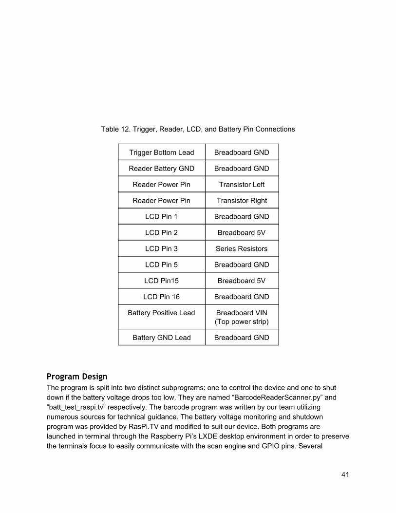
Table 12. Trigger, Reader, LCD, and Battery Pin Connections
Trigger Bottom Lead Breadboard GND
Reader Battery GND Breadboard GND
Reader Power Pin Transistor Left
Reader Power Pin Transistor Right
LCD Pin 1 Breadboard GND
LCD Pin 2 Breadboard 5V
LCD Pin 3 Series Resistors
LCD Pin 5 Breadboard GND
LCD Pin15 Breadboard 5V
LCD Pin 16 Breadboard GND
Battery Positive Lead Breadboard VIN (Top power strip)
Battery GND Lead Breadboard GND
Program Design The program is split into two distinct subprograms: one to control the device and one to shut down if the battery voltage drops too low. They are named “BarcodeReaderScanner.py” and “batt_test_raspi.tv” respectively. The barcode program was written by our team utilizing numerous sources for technical guidance. The battery voltage monitoring and shutdown program was provided by RasPi.TV and modified to suit our device. Both programs are launched in terminal through the Raspberry Pi’s LXDE desktop environment in order to preserve the terminals focus to easily communicate with the scan engine and GPIO pins. Several
41

packages are required to run the programs, including Python, GPIO, and LCD libraries. The package installation and program set-up is described in detail in Appendix M. The BarcodeReaderScanner.py program is the mastermind controlling the device. It directly controls the trigger, reader, and LCD. It also monitors the scan engine outputs. The program is arranged as a finite state machine (see Figure 21). Each state handles a different function of the device. The device’s mode (read then scan or scan then read) is set by editing line 24 of the program, which reads “Mode = True # Mode is True if in read to scan mode, false if scan to read”.
42
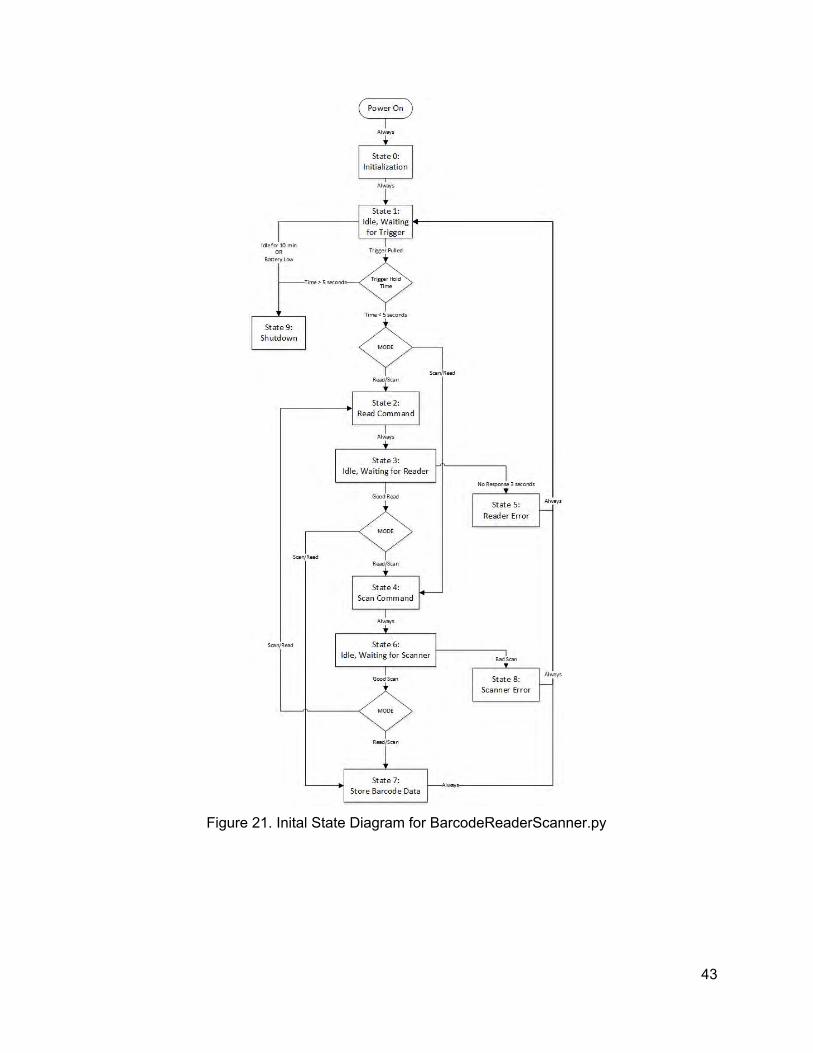
Figure 21. Inital State Diagram for BarcodeReaderScanner.py
43
Assembly
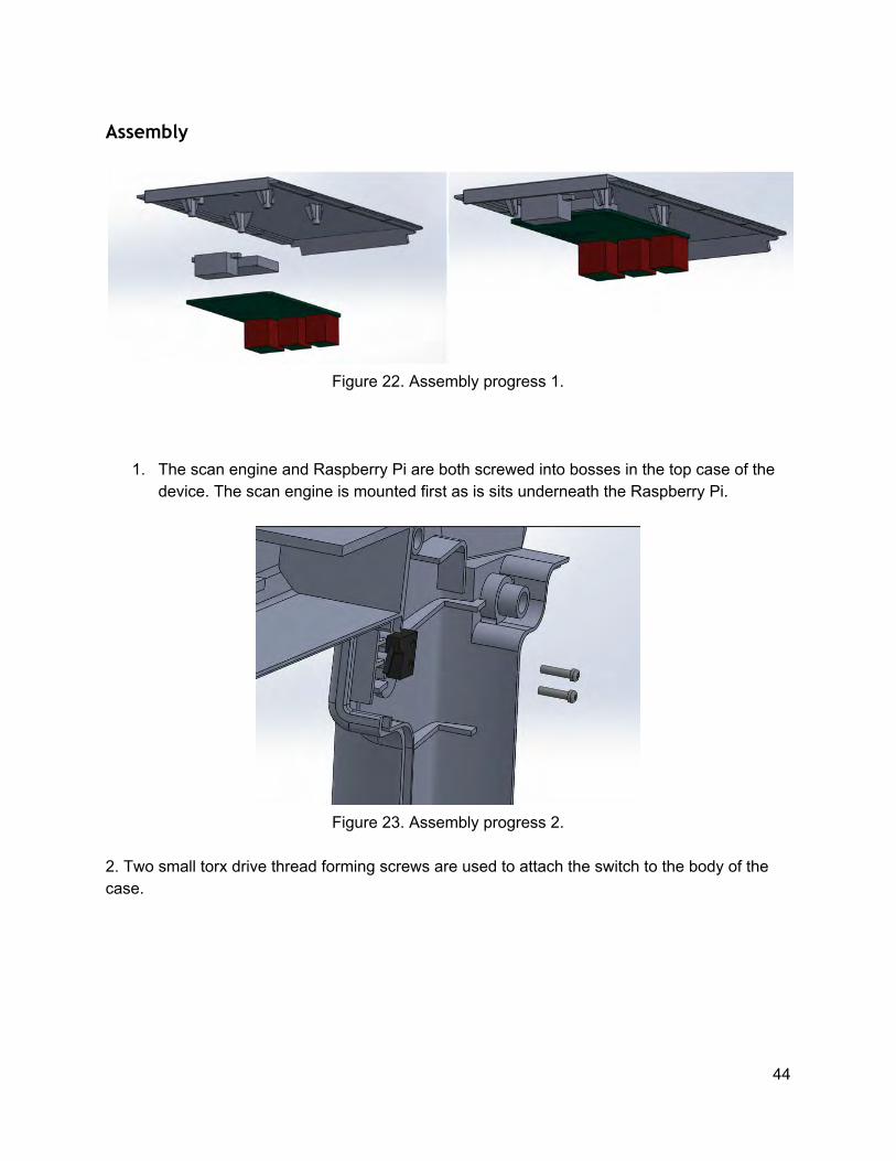
Figure 22. Assembly progress 1.
1. The scan engine and Raspberry Pi are both screwed into bosses in the top case of the device. The scan engine is mounted first as is sits underneath the Raspberry Pi.
Figure 23. Assembly progress 2.
2. Two small torx drive thread forming screws are used to attach the switch to the body of the case.
44

Figure 24. Assembly progress 3.
3. The battery is placed into the ribbing features designed to support it, while the lens for the scan engine is epoxied in place. The right side of the case can be joined with the left briefly to insure that the lense dries straight, but only apply the adhesive on the right portion of the case to allow for easy disassembly. After the battery is in place, The ‘on’ button is installed. A small cylinder of plastic (for prototyping purposes, a piece of a glue stick works well) is attached to a circular piece of tape which is then attached on the side of this grip. This allows the user to actuate the button to turn on the battery.
Figure 25. Assembly progress 4.
4. Components are slotted into the right case. The case is designed with features to accept and retain these components, although in some cases (with the taggant reader, lcd, and USB cables) and bit of glue (epoxy or even hot glue) is helpful to guarantee stability and alignment.The clear lens, LCD, taggant reader, and USB cables are installed followed by the top case assembly. After installing and wiring the taggant reader, be sure to place opaque tape over the opening used to route the taggant reader wires to isolate the reader from any ambient light.
45

Figure 26. Complete Assembly progress 5.
5. Finally, after verifying that no cables will pinch in the process, the left and right portion of the case can be brought together and secured via three screws. These screws are thread-forming and use torx drives to help prevent removal. In addition, epoxy can be added at this step to further increase the difficulty of removing the screws.
Construction The main components that have been designed and built over the course of this project are plastic parts. These parts have been designed to be compatible with the injection molding process. This includes, but is not limited to, maintaining uniform wall thickness and including appropriate layout for production in a simple single shot mold. BrandWatch Technologies has worked with a vendor in the past that has produced adequate molds. Due to the overhead associated with creating these molds, the parts will be 3D printed for this project.
46

Chapter 6: Design Verification Battery Testing Initial plans for battery testing included measuring battery duration at an idle state and at an active state. These testing plans became more extensive when issues arose that would prevent the device from running within our specifications. The first and most concerning issue was being able to safely shut down the Raspberry Pi before the battery is depleted. The first test was done with a circuit that ran the battery and measured the voltage to see if there was a fluctuation in voltage towards the end of the battery cycle noticeable enough to alert the Raspberry Pi and give it enough time to run the shut-down sequence (Figure 27).
Figure 27. Initial battery test monitoring voltage as battery discharged This test resulted in an almost instantaneous voltage drop from 5V to 0V offering no solution to the safe-shutdown issue. The succeeding test to determine battery behavior was done by connecting the multimeter directly to the battery leads and monitoring voltage as the battery discharged. This mimicked the first battery test but bypassed the regulator circuit to take the unfiltered voltage directly from the battery. This was successful because of an observed drop in voltage as the battery discharged. The experimental results were compared to theoretical results (Figure 28) to validate that our Li-Ion battery performed as expected. Results for the active battery test can be found in Appendix L.
47

Figure 28. Theoretical Li-Ion Voltage Curve for 190-1800 mAh
Scan Precision and Accuracy (Functionality) Since our device is to be used to demo technology to prospective buyers, scanning and reading precision and accuracy are both very important aspects of our design. Informal tests have been conducted throughout the prototyping process to test these pieces of the device. The scan engine has worked incredibly well since its first use, with no noticeable degradation after adding the clear acrylic screen directly in front of it. The taggant reader, while still definitely acceptable, has seen a slight decrease in reliability since its implementation into the system. Functionality testing was conducted alongside the device battery endurance testing. During the course of the test, 50 accurate reads/scans were taken at approximately 15 minute intervals (see Appendix L). Of 50 reads, 42 were successful, which is an 84% success rate. The scan engine never failed to decode a barcode during this test. A bug in the system was documented during the test. When the device experienced an extended period of inactivity (15 minutes) it read a false positive before taggant was in front of the viewfinder. The device has gone through software and battery changes since this testing took place, and the bug’s appearance rate has drastically decreased. However, it still has been documented a few times during other testing. The bug will sometimes appear after significant idle time (10-15 minutes), but it does not occur consistently when that condition is met. Scan Frequency A short scan frequency test was conducted to roughly gauge the rate at which the device can scan and read barcodes. During this test, several time trials of a minute each were conducted. The goal of each trial was to read/scan as many barcodes as possible. The trials consistently ended with 6 successful read/scan pairs each. One trials experienced a read failure, but that did not impede the devices ability to meet 6 read/scan pairs a minute.
48

Thermo Test/Ventilation test Unfortunately, time constraints did not permit a full thermodynamic test. However, during all of our extended testing, no heat related issues were noted. The system operated smoothly and there was no noticeable dissipated heat from the battery.
Performance Degradation Test The completion of the device occurred late enough in the project timeline that a full performance degradation test was not feasible. While the system was run continuously to simulate normal usage over a day, an extended multiple day test was not an option given the need for last minute tweaking and adjustments. With that being said, no noticeable performance degradation occurred during the Battery Endurance and Functionality test. The test took place over the course of 6.5 hours, the battery life of the device. Though long term performance degradation is not covered in this test, but there doesn’t appear to be any short term degradation as the device sees use until battery depletion.
Component Acceptance Tests The first tests conducted were acceptance tests on every component to ensure it functioned properly and both individually and with the Raspberry Pi. These components included the LCD, flash drive, scan engine, Wifi dongle, battery and taggant reader. Most component tests were run by plugging the respective device into the raspberry pi and checking for functionality, such as terminal output for the scan engine, moving small files in and out of the usb drive, and powering on the raspberry pi with battery power. The LCD screen required wiring to the raspberry pi and running a test program included with the LCD programming library. Each component, except for the Wifi dongle, successfully ran standing alone and successfully interfaced with the Raspberry Pi. The Wifi dongle was declared defective and was removed from the feature list, as it was an extra feature uneccessary for the devices operation, and interfacing it with the program would only occur if the project was well ahead of schedule. The Wifi dongle and its capabilities is explained in further detail in Chapter 7. A second round of component testing took place to confirm that the polystyrene screen and reader screen did not impede scanner/reader functionality. The screen tested resulted in switching from an anti-glare screen to a clearer sheet of the same material. The reader screen testing confirmed that the reader could still detect taggant through the thicker screen used on the device.
49

Chapter 7: Conclusions and Recommendations Wifi Capability In the beginning of the design development stage, a Wifi dongle was considered to wirelessly transmit data the device processed. This feature offers a variety of benefits including the convenience of not having to transfer the barcode information from the USB port of the IR Barcode Scanner an external USB port. This feature would restrict the device to Wifi enabled areas and requires more complex software development to connect the device to the network. Unfortunately, we unable to explore this alternative data storage due to time constraints and a cheap, defective Wifi dongle that was purchased. However, after speaking with BrandWatch Technologies, this feature is popular among potential customers and further consideration should be taken for this feature. Battery Considerations One significant design trade-off that was considered was handle ergonomics versus battery life. In order to meet battery charge storage requirements, a comfortable handle was sacrificed. Moving forward it is recommended that a custom battery should be considered in order to have a device with an ergonomic handle that meets the battery life requirement. In addition, one of the major issues we ran into twice, was shorting the battery so that it was unusable. This was the result of a faulty PCB that we had designed and improper construction procedures. Moving forward, a correctly designed PCB and handling the battery during construction with more precaution would’ve have saved time and money. Future Testing Time constraints prevented multiple tests from taking place that are recommended to be completed before this product reaches goes to market. All of the tests were prioritized in order of meeting the key specifications for an adequate device. The following test are for additional information to improve the existing device for optimization. As mentioned in Chapter 6, thermal testing was considered to ensure the safety of the user and to prevent it from damaging itself. Heat dissipating from the different components should be evaluated quantitatively. Quantifying the intuitive use, ergonomic and easy to change battery specifications requires user studies. This was planned to be done with a sizable group of non-biased participants. Each study should be organized to include a control, in most cases a competitor’s device, to baseline the results. These tests should be utilized to provide the most ergonomic, intuitive solution possible.
50

Initial testing plans required a drop test to ensure the impact would not cause damage. Since this is a device that will be used day-to-day, rigidity is essential. Accounting for impact was resolved by including a wristband to provide a safety in the case that the device does fall from a user’s hand. This is sufficient for prototyping purposes, however drop tests are recommended in order to meet the requirements of commercial work environments. Instron testing was intended to be utilized to validate FEA models. The most important simulation that can easily be run is a simple 3-point bend with the front of the device and the bottom of its handle as the two support points. The device is fixed on a flat surface beneath the Instron and should be pressed by a flat instron head at the tallest point of the device. While in talks with BrandWatch, it was determined that a wrist strap would be used to help prevent a user from accidentally dropping the device. This should reduce the incidents of drop events in the field and de-emphasizes the need for the instron and drop tests to be conducted. However, WatchKeepers recommends that these types of tests are run before any future product based on this design is finalized to eliminate any weak points and guarantee its robustness.
Appendices Appendix A: Quality Function Deployment Appendix B: Decision Matrices Appendix C: Pairwise Requirement Matrix Appendix D: Gantt Chart Appendix E: Wiring Diagram Appendix F: Battery Charge Calculation Appendix G: Battery Heating Calculation Appendix H: Barcode Assembly Instructions Appendix I: Deflection Analysis Appendix J: Case Drawings Appendix K: Failure Mode and Effects Analysis Appendix L: Battery Endurance and Functionality Test Log Appendix M: Raspberry Pi Programming Set-up Appendix N: Operator’s Manual with Safety Guidelines Appendix O: Bibliography
51

Measures
Pro
duct
has
cap
abili
ty fo
r sca
nnin
g 1-
D &
2-D
Use
r has
cap
abili
ty to
sw
itch
mod
es
Dev
ice
has
capa
bilty
to s
tore
X b
arco
des
Last
s X
num
ber o
f hou
rs in
idle
Last
s X
num
ber o
f sca
ns e
very
5 s
econ
ds
LCD
that
pro
vide
s hu
man
inte
rface
Wei
ghs
less
than
X lb
s. a
nd fi
ts w
ithin
X ft
^3
Use
r tes
t; 90
% s
ucce
ss ra
te c
ompa
red
to c
ompe
titor
Visu
al o
r aud
itory
que
ue th
at s
igna
ls p
rese
nce
of ta
ggan
t
Use
r stu
dy; 9
0% s
ucce
ss ra
te
Use
r stu
dy; 9
0% s
ucce
ss ra
te
Func
tiona
l afte
r 5 4
foot
dro
ps
Sur
vive
s te
st re
pres
enta
tive
of d
aily
use
At g
iven
dis
tanc
e ou
r mod
el w
ill re
ad 9
0% a
s cu
rren
t sta
nd a
nlon
e
No
grea
ter t
han
10%
deg
rada
tion
of s
cann
ing
relia
bilit
y af
ter 1
0000
cal
ls
Use
r tes
t; m
axim
um o
f 5 s
teps
to re
plac
e pa
rt
All
elec
troni
c co
mpo
nent
s ar
e re
adill
y av
aila
ble
Cos
t with
in 5
0% g
reat
er th
an c
ompe
titio
n
Verif
y al
l com
pone
nts
are
man
ufac
tura
ble
A B C D E F G H I J K L M N O P Q R S 1 2 3 4 5Scans 1-D & 2-D Barcodes 1 17 9 3 0 0 0 0 3 0 0 0 0 0 0 0 0 0 0 3 1Multiple modes for scanner/reader interaction2 12 0 9 0 0 0 0 3 0 3 1 0 0 0 0 0 0 0 0 0Store multiple barcodes in device 3 5 0 1 9 0 0 0 3 0 0 0 0 0 0 0 0 0 0 1 1Battery Life 4 7 3 0 0 9 9 3 3 0 3 0 0 0 0 0 0 0 0 0 0LCD screen 5 2 0 0 0 1 0 9 3 0 3 3 0 0 0 0 0 0 0 1 1Portable 6 7 1 0 1 3 0 3 9 3 0 0 1 0 0 0 0 0 0 0 0Ergonomic 7 6 0 1 1 0 0 0 0 9 0 0 1 0 0 0 0 1 0 0 1Mode that relays presence of taggant8 15 0 9 3 0 0 3 1 0 9 0 0 0 0 0 0 0 0 0 0Intuitive use 9 13 0 3 3 0 0 3 0 3 3 9 9 0 0 0 0 3 0 0 0Easy to change battery 10 6 0 0 0 0 0 0 1 0 0 3 9 0 0 0 0 1 0 0 1Survive drop off 4 foot table 11 8 0 0 0 0 0 3 3 0 0 0 0 9 9 0 0 0 0 0 13 Point Bend test 12 2 0 0 0 0 0 1 3 0 0 0 0 3 9 0 0 0 0 0 190& performance vs. current models13 15 0 1 0 0 0 0 0 0 0 0 0 0 0 9 3 0 0 0 0Reads reliably through 10000 calls 14 13 1 3 1 0 0 3 0 0 3 0 0 0 0 3 9 0 0 0 0Parts are easily replacable 15 1 1 0 0 0 0 3 3 0 1 3 3 0 0 0 0 9 0 3 3Functioning electronic component COTS16 8 1 3 3 0 0 3 0 0 0 0 0 0 0 0 0 0 9 1 0Cost 17 6 3 0 1 0 0 1 0 0 0 0 0 0 0 0 0 0 3 9 1All parts for mass production process18 10 0 0 0 0 0 1 0 0 0 0 0 0 0 0 0 0 3 0 9All parts for mass production process18 10 0 0 0 0 0 1 0 0 0 0 0 0 0 0 0 0 3 0 9
Strong - 9 Good 5Medium-3 4Weak - 1 Company Ratings 3
2Relationship Strength Bad 1
Targets
1-D
& 2
-D
2+ M
odes
500
Bar
code
s
12 H
ours
6 H
ours
LCD
Inte
rface
1.5
lbs.
& 1
ft. C
u.
90%
Sat
isfa
ctio
n
Aud
io &
Vis
ual
90%
Sat
isfa
ctio
n
90%
Sat
isfa
ctio
n
Suc
cess
ful o
n 5+
4 ft
. dro
p te
st
Pas
ses
3 po
int b
end
test
>90%
<10%
< 5
step
s
0 irr
epla
cabl
e pa
rts
<150
% c
ompe
titio
n pr
ice
100%
man
ufac
tura
bilit
y
Weighted Importance 323 396 110 91 63 74 245 90 375 247 138 96 36 180 156 14 144 108 290
% Importance 10 12 3 3 2 2 8 3 12 8 4 3 1 6 5 0 5 3 9
3176
Impo
rtanc
e
Item
No.
Voices Gro
upin
g
Cus
tom
er
Customer Ratings
Bad
Goo
d

Appendix B: Relay Information Decision Matrix
Specification Weight LEDs Speakers LCD Screen Haptics
Alarm Clock Display Projector
Intuitive use 0.15 0 0 2 -1 1 1
Works reliably after five sets of four foot drops 0.1 0 0 -1 0 -1 0
Non-Custom Component Availability 0.05 0 -1 0 0 0 -1
Battery life 0.15 0 2 -2 -2 -2 0
Weight 0.075 0 -1 -3 -1 -2 -1
Size 0.075 0 -1 -3 -1 -2 -1
Ergonomics 0.25 0 1 3 1 1 1
Cost 0.15 0 1 -3 1 -2 -3
Total 1 0 0.5 -0.25 -0.2 -0.6 -0.25

Appendix B: Trigger Device Decision Matrix
Specification Weight
Single Pull Trigger
Two-Pull Trigger
Touch Screen Contact
Always On
Two Seperate Triggers
Intuitive Use 0.15 0 -1 0 -1 -1 -1
Performance Degredation After 10,000
Cycles 0.1 0 -1 -1 -1 -1 -1
Multiple Mode Interface 0.25 0 0 1 0 0 1
Four Foot Drop Reliability 0.05 0 0 -2 -1 0 0
Non-Custom Component Availability 0.1 0 -1 -1 0 0 0
Battery life 0.1 0 0 -3 0 -2 0
Weight 0.075 0 0 -2 -1 0 -1
Size 0.075 0 -1 -3 -1 0 -1
Ergonomics 0.05 0 0 1 0 2 -2
Cost 0.05 0 -1 -3 0 -1 -1
Total 1 0 -0.475 -0.825 -0.45 -0.4 -0.3

Appendix B: Mode Switching Decision Matrix
Specification Weight Buttons Touch Screen Dial
Scroll Wheel Switch
Intuitive Use 0.2 0 2 1 -1 1
Performance Degradation After 10,000 Cycles 0.1 0 -1 0 -1 0
Four Foot Drop Reliability 0.075 0 -3 0 -1 0
Non-Custom Component Availability 0.1 0 -1 0 -1 0
Battery life 0.1 0 -3 0 0 0
Weight 0.1 0 -2 0 -1 0
Size 0.1 0 -3 -1 -1 0
Ergonomics 0.1 0 2 1 1 1
Cost 0.075 0 -3 0 -1 0
LCD Compatability 0.05 0 1 0 0 0
Total 1 0 -0.8 0.2 -0.65 0.3

Appendix C: Pairwise Requirement Comparison 1 2 3 4 5 6 7 8 9 10 11 12 13 14 15 16 17 18
1 x 1 1 1 1 1 1 1 1 1 1 1 1 1 1 1 1 1
2 x 2 2 2 2 7 2 9 2 2 2 13 14 2 2 2 2
3 x 4 3 6 3 8 9 10 11 3 13 14 3 16 3 18
4 x 4 4 4 8 9 10 11 4 13 14 4 16 4 18
5 x 6 7 8 9 10 11 12 13 14 5 16 5 18
6 x 6 8 9 6 11 6 13 14 6 16 6 18
7 x 8 9 7 11 7 13 14 7 16 7 18
8 x 8 8 8 8 8 8 8 8 8 8
9 x 9 9 9 13 14 9 9 9 9
10 x 10 10 13 14 10 16 17 18
11 x 11 13 11 15 11 17 18
12 x 13 14 12 16 17 18
13 x 13 13 13 13 13
14 x 14 14 14 14
15 x 16 17 18
16 x 17 18
17 x 17
18 x

Appendix C: Pairwise Requirement Comparison Results Requirement Number Score Weight
Scans 1-D & 2-D barcodes 1 17 11.1
Multiple modes for scanner/reader interaction 2 12 7.8
Store multiple barcodes on device 3 5 3.3
Battery life 4 7 4.6
LCD Screen 5 2 1.3
Portable 6 7 4.6
Ergonomic 7 6 3.9
At least one mode that relays presence of taggant
to user 8 15 9.8
Intuitive use 9 13 8.5
Easy to change battery 10 6 3.9
Survive drop off 4 ft. table 11 8 5.2
3 point bend test 12 2 1.3
Perfom at least 90% as well as current standalone
devices 13 15 9.8
Reads reliably through 10,000 calls 14 13 8.5
Parts are easily replacable 15 1 0.7
Functioning electronical components are COTS 16 8 5.2
Cost effective 17 6 3.9
Parts are manufacturablefor mass production 18 10 6.5

ID Task Name Start Finish % Complete1 Project Proposal Tue 9/30/14 Tue 10/21/14 100%5 Preliminary Design Report Tue 10/21/14 Tue 11/18/14 100%21 Detailed Design Tue 11/18/14 Fri 1/30/15 100%24 Electronic Analysis Mon 1/5/15 Tue 2/10/15 100%25 Power Calculations Mon 1/5/15 Tue 1/6/15 100%26 Wiring Diagrams Mon 1/5/15 Tue 2/10/15 100%27 Hardware Analysis Mon 1/5/15 Tue 2/10/15 100%28 Handle Ergonomics Mon 1/5/15 Fri 1/16/15 100%29 Battery Housing Mon 1/5/15 Fri 1/23/15 100%30 Raspberry Pi Placement Sat 1/17/15 Tue 1/27/15 100%31 Taggant Board Placement Sat 1/17/15 Tue 1/27/15 100%32 Heat Calculations Tue 1/20/15 Fri 1/30/15 100%33 Trigger Placement Sat 1/24/15 Tue 2/3/15 100%34 Front Face Tue 2/3/15 Fri 2/6/15 100%35 Housing Fasteners Fri 2/6/15 Tue 2/10/15 100%36 Software Analysis Mon 1/5/15 Sun 5/17/15 100%37 Program LCD Wed 4/1/15 Sun 5/17/15 100%38 Program Image Capture Wed 4/1/15 Sun 5/17/15 100%39 Program Image Analyze Wed 4/1/15 Sun 5/17/15 100%40 Program Image Output Wed 4/1/15 Sun 5/17/15 100%41 Battery Shutdown Mon 1/5/15 Mon 1/5/15 100%42 Data Storage Mon 1/5/15 Mon 1/5/15 100%43 Program Flow Mon 1/5/15 Mon 1/5/15 100%44 Make Flow Chart Mon 1/5/15 Sat 2/28/15 100%45 Final Design Report Tue 2/10/15 Tue 2/10/15 100%46 Critical Design Review Tue 2/10/15 Tue 2/10/15 100%47 Constructing Prototype Tue 2/10/15 Sun 5/10/15 100%48 Finalize Ordering Parts Tue 2/10/15 Tue 2/24/15 100%49 3‐D Print Component: Iteration 1 Thu 2/19/15 Thu 3/19/15 100%50 3‐D Print Components: Iteration 2 Thu 3/19/15 Fri 4/24/15 100%51 Cut Lens: Iteration 1 Sun 3/1/15 Fri 4/17/15 100%52 Cut Lens: Iteration 2 Fri 4/24/15 Fri 5/1/15 100%53 Assemble Prototype Fri 4/24/15 Sun 5/10/15 100%54 Test Prototype Mon 12/1/14 Fri 6/5/15 100%55 Camera Acceptance Test Mon 12/1/14 Tue 1/6/15 100%56 Raspberry Pi Acceptance Test Mon 12/1/14 Tue 1/6/15 100%57 Battery Acceptance Test Fri 1/30/15 Tue 2/24/15 100%58 Functionality test Mon 4/13/15 Mon 4/27/15 100%59 Taggant Test Fri 4/17/15 Mon 5/4/15 100%60 Ventilation Debris Test Fri 5/1/15 Mon 5/11/15 100%61 Temperature Validation Fri 5/1/15 Mon 5/11/15 100%62 Camera Focus Test Sun 3/22/15 Mon 5/18/15 100%63 Idle Battery Life Fri 4/10/15 Fri 5/8/15 100%64 Performance Degradation Test Fri 5/1/15 Mon 5/11/15 100%65 Active Battery Test Fri 4/10/15 Fri 5/8/15 100%66 Intuitive Use Test Mon 4/20/15 Mon 5/4/15 100%67 Ergonomics Test Mon 4/20/15 Mon 5/4/15 100%68 Scan Frequency Test Mon 4/20/15 Fri 5/8/15 100%69 Senior Design Expo Fri 5/29/15 Fri 5/29/15 100%70 Final Project Report Fri 6/5/15 Fri 6/5/15 100%
Watchkeeper's Gantt Chart
Appendix D: Gantt Chart

GN
DVC
CV0 RS R/
W E DB0
DB1
DB2
DB3
DB4
DB5
DB6
DB7 BL
1BL
2
Scan Engine
USB
3.3VGPIO 2 GPIO 3GPIO 4GNDGPIO 17GPIO27GPIO223.3 VGPIO 10GPIO 9 GPIO 11GNDID_SDGPIO 5GPIO 6GPIO 13GPIO 19GPIO 26GND
5V5VGNDGPIO 14GPIO 15GPIO 18GNDGPIO 23GPIO 24GNDGPIO 25GPIO 8GPIO 7ID_SCGNDGPIO 12 GND GPIO 16GPIO 20GPIO 21
LCD Screen
12
34
56
78Taggant
Reader
Raspberry Pi
Backlight Control

Appendix F: Required Battery Storage Calculations Calculate:
1. Required battery current output with devices active 2. Required Battery charge storage to keep device running for 8 hours with a scan once
every 5 seconds
Given:
• Raspberry Pi current draw is iPiA = 0.33 A active, iPiI = 0.21 A idle • LCD current draw is iLCD = 0.045 A • Scan Engine current draw is iSEA = 0.303 A active and iSEI = 0.057 A idle • Reader current draw is iReadA = 0.30 A active and off while idle • Raspberry Pi ports provide power at EPi = 80% efficiency
Assumptions:
• LEDs, buttons, other components draw insignificant amount of power • While scanning, device is drawing power at scanning current for 1 second. Then, while
reading, device is drawing power at reading current for 1 second. Otherwise, device power draw is modeled as if it were idle.
Solution:
First, set up equations for the current draw of all the components considered in each state:
The LCD, Reader, and Scan Engine draw power from ports on the Raspberry Pi, so their current draw should be modified to account for the port efficiency of the Pi. This yields the total current draw of the Pi with its ports in use:
Use the first equation to find the scanning current draw:

Use the second equation to find the reading current draw:
Use the third equation to find the idle current draw:
These current draws are within the rated amperage provided by our selected battery, which is 1 A. Note that based on these calculations, it is impossible to scan and read at the same time.
To find the necessary battery charge storage in Amp-hours, simply multiply the current draw by the 8 hours required. Since the device will only scan once every 5 seconds, the current draw over those 5 seconds will be split between the idle, scanning, and reading states.
Battery selection was primarily driven by this required storage and the size constraints of the grip. The smallest battery meeting this requirement from our selection was a 4400 mAh capacity USB battery pack sold by Adafruit.

Appendix G: Battery Heating Calculations Calculate:
1. Steady State Temperature of Battery
Given:
• iidle = 0.3375 A • iscan = 0.7650 A • iread = 0.8325 A • Vbattery = 5 V • kABS = 1.35 in BTU/h ft2 F • hstill air = 10.45 W/m2 K • tABS = 2 mm • Battery size 100x42x23 mm • Battery efficiency of 80%
Assumptions:
• Room Temperature of 23 C • Battery is idle for 3 seconds, scanning for 1second, and reading for 1 second for every 5
second period over the course of 8 hours • Battery dissipates heat through handle alone • Simple 1-D conduction through grip • Neglect insulation caused by user's hand
Solution:
First, find the average current output:
Then, find the power going into the Raspberry Pi:
The battery send power to the Pi at 80% efficiency, so the battery actually produces more power, some of which is lost to heating.

Of the total battery power, 20% will be dissipated as heat.
For the calculations, we will treat the handgrip around the case as a wall with surface area equal to that of the battery in contact with ABS plastic. This wall will be 2mm thick and exposed to still air. The resistance equations for the ABS plastic wall and still air are as follows:
The Heat Transfer equation is:
Reorganized to solve for Interior Temperature:
This value is well within the safe operating temperature of the battery (max 50C). Furthermore, the device should also be safe at higher temperatures, such as 30C, which may be reached in warehouse settings.

NAME:
PART:
DRAWING REV:
MATERIAL:
OP# Operation Description Parts Required Tooling & Fixtures Required OP Time (min) Approval
10Align the Lower Components the be inserted
into the left case.
Case Left, Female with
Housing, Battery, Switch,
Trigger, USB Female, LCD
Screen, Reader, Bottom
Screen
N/A
20
Slide in Reader into the the designated slot
with the scan indicator facing outside of the
case.
Reader N/A
30
Attach the connection cable into the Female
Housing then place the component into the
bottom of the handle case shown in the
exploded view.
Female Housing, Conector
cable, Left CaseN/A
40
Place Battery inside the left case of the
handle. Adjust the wire from the Female
Housing up through the handle to be attached
into the top of the battery.
Battery N/A
50
Attach the connection cable into the USB
female and place it in the back of the left case
with the port directed outward of the case.
USB Female, Connector Cable N/A
60 Place the LCD Screen into the left case. LCD Screen N/A
70Slide in the Switch and button with the same
orientation as the exploded view. Switch, TriggerN/A
Notes: More Detailed desciption of setup will be included once the first prototype has been assembled.
PART ROUTING/ JOB PLANNER
WatchKeepers
IR Barcode Reader
A
ABS Plastic
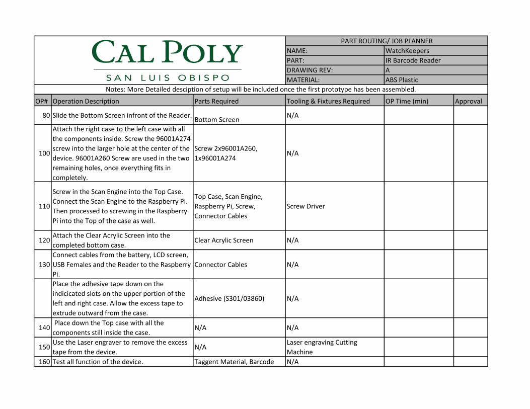
NAME:
PART:
DRAWING REV:
MATERIAL:
OP# Operation Description Parts Required Tooling & Fixtures Required OP Time (min) Approval
80 Slide the Bottom Screen infront of the Reader.Bottom Screen
N/A
100
Attach the right case to the left case with all
the components inside. Screw the 96001A274
screw into the larger hole at the center of the
device. 96001A260 Screw are used in the two
remaining holes, once everything fits in
completely.
Screw 2x96001A260,
1x96001A274N/A
110
Screw in the Scan Engine into the Top Case.
Connect the Scan Engine to the Raspberry Pi.
Then processed to screwing in the Raspberry
Pi into the Top of the case as well.
Top Case, Scan Engine,
Raspberry Pi, Screw,
Connector Cables
Screw Driver
120Attach the Clear Acrylic Screen into the
completed bottom case. Clear Acrylic Screen N/A
130
Connect cables from the battery, LCD screen,
USB Females and the Reader to the Raspberry
Pi.
Connector Cables N/A
Place the adhesive tape down on the
indicicated slots on the upper portion of the
left and right case. Allow the excess tape to
extrude outward from the case.
Adhesive (S301/03860) N/A
140 Place down the Top case with all the
components still inside the case. N/A N/A
150Use the Laser engraver to remove the excess
tape from the device.N/A
Laser engraving Cutting
Machine
160 Test all function of the device. Taggent Material, Barcode N/A
Notes: More Detailed desciption of setup will be included once the first prototype has been assembled.
WatchKeepers
IR Barcode Reader
A
ABS Plastic
PART ROUTING/ JOB PLANNER

Deflection AnalysisTuesday, February 3, 20158:40 PM
New Section 1 Page 1

New Section 1 Page 2

New Section 1 Page 3

;
'
&
%
$$
%
&
'
7+(,1)250$7,21&217$,1(',17+,6'5$:,1*,67+(62/(3523(57<2):$7&+.((3(56$1<5(352'8&7,21,13$5725$6$:+2/(:,7+2877+(:5,77(13(50,66,212):$7&+.((3(56,6352+,%,7('
35235,(7$5<$1'&21),'(17,$/
1(;7$66< 86('21
$33/,&$7,21
',0(16,216$5(,10072/(5$1&(6 )5$&7,21$/$1*8/$50$&+ %(1'7:23/$&('(&,0$/7+5((3/$&('(&,0$/
,17(535(7*(20(75,&72/(5$1&,1*3(5
0$7(5,$/
),1,6+
'5$:1
&+(&.('
(1*$335
0)*$335
4$
&200(176
'$7(1$0(
7,7/(
6,=(
%':*12 5(9
:(,*+76&$/(
81/(6627+(5:,6(63(&,),('
,/
6+((72)
&$6(/()7
'21276&$/('5$:,1*
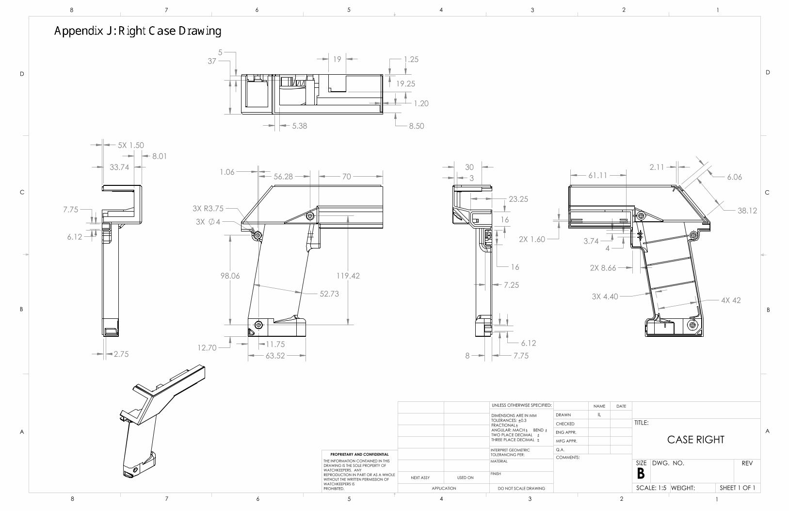
;5
;
;
;
;
;;
'
&
%
$$
%
&
'
7+(,1)250$7,21&217$,1(',17+,6'5$:,1*,67+(62/(3523(57<2):$7&+.((3(56$1<5(352'8&7,21,13$5725$6$:+2/(:,7+2877+(:5,77(13(50,66,212):$7&+.((3(56,6352+,%,7('
35235,(7$5<$1'&21),'(17,$/
1(;7$66< 86('21
$33/,&$7,21
',0(16,216$5(,10072/(5$1&(6 )5$&7,21$/$1*8/$50$&+ %(1'7:23/$&('(&,0$/7+5((3/$&('(&,0$/
,17(535(7*(20(75,&72/(5$1&,1*3(5
0$7(5,$/
),1,6+
'5$:1
&+(&.('
(1*$335
0)*$335
4$
&200(176
'$7(1$0(
7,7/(
6,=(
%':*12 5(9
:(,*+76&$/(
81/(6627+(5:,6(63(&,),('
,/
6+((72)
&$6(5,*+7
'21276&$/('5$:,1*

;
;
;
$$
%%
;
;
; ;
;
;
6(&7,21$$
56(&7,21%%
'
&
%
$$
%
&
'
7+(,1)250$7,21&217$,1(',17+,6'5$:,1*,67+(62/(3523(57<2):$7&+.((3(56$1<5(352'8&7,21,13$5725$6$:+2/(:,7+2877+(:5,77(13(50,66,212):$7&+.((3(56,6352+,%,7('
35235,(7$5<$1'&21),'(17,$/
1(;7$66< 86('21
$33/,&$7,21
',0(16,216$5(,10072/(5$1&(6 )5$&7,21$/$1*8/$50$&+ %(1'7:23/$&('(&,0$/7+5((3/$&('(&,0$/
,17(535(7*(20(75,&72/(5$1&,1*3(5
0$7(5,$/
),1,6+
'5$:1
&+(&.('
(1*$335
0)*$335
4$
&200(176
'$7(1$0(
7,7/(
6,=(
%':*12 5(9
:(,*+76&$/(
81/(6627+(5:,6(63(&,),('
,/
6+((72)
&$6(723
'21276&$/('5$:,1*

,7(012 3$57180%(5 '(6&5,37,21 47< &5/07' &2'(&RUS6FDQ(QJLQH &DVH7RS $%63ODVWLF0DWHULDO 5DVSEHUU\3L%&LUFXLW%RDUG /&'6FUHHQ &DVH5LJKW $%63ODVWLF0DWHULDO ++ %UDQG:DWFK5HDGHU $GDIUXLW%DWWHU\ 86%BIHPDOH 6WDU7HFK86%)HPDOH IHPDOHBZBKRXVLQJ 6WDU7HFK86%)HPDOH 7ULJJHU 7ULJJHU([WHQVLRQ 7RSBVFUHHQ 1RQJODUH6WU\HQH6KHHW %RWWRPBVFUHHQ %UDQG:DWFK6FUHHQ 6:1' 'LJL.H\7ULJJHU &DVH/HIW $%63ODVWLF0DWHULDO $ 0F0DVWHU&DUU7KUHDG6FUHZ $ 0F0DVWHU&DUU7KUHDG6FUHZ $ 0F0DVWHU&DUU6FUHZ
'
&
%
$$
%
&
'
7+(,1)250$7,21&217$,1(',17+,6'5$:,1*,67+(62/(3523(57<2),16(57&203$1<1$0(+(5(!$1<5(352'8&7,21,13$5725$6$:+2/(:,7+2877+(:5,77(13(50,66,212),16(57&203$1<1$0(+(5(!,6352+,%,7('
35235,(7$5<$1'&21),'(17,$/
1(;7$66< 86('21
$33/,&$7,21
',0(16,216$5(,1PLOOLPHWHUV72/(5$1&(6)5$&7,21$/$1*8/$50$&+ %(1'7:23/$&('(&,0$/7+5((3/$&('(&,0$/
,17(535(7*(20(75,&72/(5$1&,1*3(5
0$7(5,$/
),1,6+
'5$:1
&+(&.('
(1*$335
0)*$335
4$
&200(176
'$7(1$0(
7,7/(
6,=(
%':*12 5(9
:(,*+76&$/(
81/(6627+(5:,6(63(&,),('
6+((72)
$VVHP'21276&$/('5$:,1*
([SORGHG9LHZRI,5%DUFRGH5HDGHU

Report Date 4/27/2015 Sponsor: BrandWatch
Quantity Type Start date Finish date Test Result Quantity Pass Quantity Fail
1TemperatureValidation
Physically determine ifdisspated heat can be feltthrough the handle
If heat can be felt, proceed tothermocouple testing fortemperature validation. If noheat felt, test passes Justin Prototype Unit 1 prototype 5/1/2015 5/11/2015 Pass 1 0
3 Functionality TestTest the functionality of theassembled device
both modes fully functional,detects taggant in sampleand detects 2 samplebarcodes Tony Prototype Unit 2 prototype 4/13/2015 4/27/2015 Pass 2 0
6 Scan Frequencytest multiple codes at correctfocal length
Can scan 3 codes in 9seconds Justin Prototype Unit 1 final 4/20/2015 4/27/2015 Pass 1 0
7 Taggant Testtest for taggant detection atdistance of .25 inches
confirms presence of taggantin all 5 samples Justin Part 1 part 4/17/2015 4/20/2015 Pass 1 0
9PerformanceDegradation
Ensure barcodescanner/taggant reader do nodegrade over a 6.5 hourbattery life
confirms presence of taggantin all 5 samples Mark Part 1 final 5/1/2015 5/11/2015 Pass 1 0
10 Idle Battery LifeTurn device on, leave for 24hours
still retains battery life aftertest Mark Prototype Unit 2 prototype 4/10/2015 4/24/2015 Pass 1 0
11 Active Battery LifeTrigger device every 5seconds still retains battery after test Mark Prototype Unit 2 prototype 4/10/2015 4/24/2015 Pass 1 0
12 ErgonomicsUser study where asked howcomfortable use of device is
Average user rating forintuitive use 7/10 or greater Tony Prototype Unit 1 prototype 4/20/2015 5/4/2015 Pass 1 0
14Raspberry PiAcceptance Test
Verify that Raspberry Pi is notdefective
Raspberry Pi powers on, isprogrammable. Isaac Part 1 part 11/28/2014 11/28/2014 Pass 1 0
15Camera AcceptanceTesting
Verify that Camera is notdefective
Camera records videothrough Pi Isaac Part 1 part 11/28/2014 11/28/2014 Pass 1 0
16Battery AcceptanceTesting
Verify that battery is notdefective
Battery charges, providespower, and does notexplode. Mark Part 1 part 2/19/2015 2/24/2015 Pass 1 0
8 Intuitive Use
User study where user isbriefly instructed on how touse device
Average user rating forintuitive use 7/10 or greater Tony Prototype Unit 1 prototype 4/20/2015 5/4/2015 Removed
Removed due totime constraints.Sponsor will betesting intuitive usepotentialcustomers
4 Camera Focusverify camera in focus atgiven distance specified
Check Scaning ranges fordifferent barcodes, verify thatdevice can scan at differentranges Isaac Part 1 part 3/22/2015 3/27/2015 Removed 1 0
Different imagecapturing deviceused. Test isirrelevant
5 Drop Testdrop from 4 feet in randomorientation 4 times
fully functional, detectspresense of taggant in all 5samples, no visual damage Justin Prototype Unit 1 prototype Removed
Test does notprovide valuableinsight forprototype
13 3 Point Bend TestProduct subject to point loadof 20 pounds Device does not yield Isaac Prototype Unit 2 prototype Removed
Test does notprovide valuableinsight forprototype
2Ventilation DebriCheck Visual inspection of ventilation
probe can be inserted fullythrough vents Tony Prototype Unit 2 prototype 5/1/2015 5/11/2015 Removed
Removed due totime constraints.
Appendix K: Watchkeepers DVP&RDr. Peter Schuster Component/Assembly REPORTING ENGINEER:
TEST PLAN TEST REPORT
Item No
Specification orClause Reference Test Description Acceptance Criteria
Test Responsibility Test Stage
SAMPLES TESTED TIMING TEST RESULTS
NOTES

Appendix L: Battery Endurance and Functionality Test Log
Purpose
Measure the battery life of the full electronic device and determine the taggant reading and barcode
scanning success rates. This test accounts for both the inactive and active battery life, as changes to the
program and scanning mode have mitigated the differences between inactive and active modes.
Test Set Up
For this test, the device's electronic components were wired together as in the final product and tested
without the case. Before the test began, the battery was fully charged, as signified by four complete LED
bars on the front of the battery case. The battery shutdown circuitry was assembled, but the battery
shutdown program was temporarily changed such that it stored the battery log information and could
not shut the device down. The device was reprogrammed such that the scan engine is constantly on,
which accounts for the majority of the power draw along with the raspberry pi. This programming
change made the power difference between active and inactive modes insignificant, thus this test
accounts for both modes. A voltmeter was requisitioned to take precise voltage measurements across
that battery and compare them to the program's calculated voltage.
Test Procedure
After turning the device on, the device was cycled approximately every fifteen minutes according to the
following procedure.
Measure the voltage across the battery leads and record both the time the
measurement was take.
Operate the device by pulling the trigger, reading a sample of taggant, then scanning a
barcode if the reading succeeds.
Repeat the previous step twice more (three times total) and record the success/failure
of reading the taggant and scanning the barcode.
Results
Table XXX.1 was generated from the data recorded by the observer during the test. A separate file has
been attached with the data collected from the battery shutdown program, which logged time and

voltage. Consistently, the device reported a successful read whenever it was not in use for fifteen
minutes or more. These false positives were identified because the device circuitry displayed "READ
SUCCESS" before the taggant sample was placed before the reader. However, this test took place before
the battery failed and was replaced. After replacing the battery, this error has only been observed twice
after roughly twenty reads that took place during device debugging. It should be noted that the device
has not read a false positive during frequent operation (less than 5 minutes between reads/scans).
Ignoring the false positives, there were a total of fifty recorded readings. Forty-two of these readings
detected taggant in the sample, a success rate of 84%. The device never failed to scan the barcode.
Figure XXX.1 compares the data from the voltmeter and battery program. The voltmeter consistently
recorded less voltage than the program, but the two curves descend at different rates. The program
voltage curve was used to identify a voltage of 3.8 V (program calculated) as an appropriate self-
commanded shutdown point for the device. The battery lasted 6 hours and 35 minutes before running
to low to power the device.
Figure XXX.1: Battery voltage measured by voltmeter and recorded by battery program compared to
test duration.
3
3.2
3.4
3.6
3.8
4
4.2
4.4
4.6
4.8
5
0 50 100 150 200 250 300 350 400 450
Bat
tery
Vo
ltag
e (
V)
Time (Minutes)
Program Voltage
Measured Voltage

Table XXX.1: Voltage measured via voltmeter and functionality test results.

Appendix M: Raspberry Pi Programming Set-up
Purpose: This appendix describes the process of re-installing the operating system, downloading
necessary packages, and re-installing the program should the raspberry pi experience a critical
error or other reasons for a full-reset.
Process:
1. Install Raspbian operating system on the mirco-SD card.
2. Program the raspberry pi to startup without requiring username and password.
3. Install packages necessary for the program.
4. Mount USB drive
5. Set-up Barcode program and Battery program.
Installing Raspbian:
The process for installing the Rasbian operating system on the pi is described by the Raspberry
Pi Foundation on their website (Resource 1). Download the disk image from this website and
install it on the SD card. The process differs depending on which operating system is used, but
the general process is as follows:
1. Download Raspbian Disk image from Raspberry Pi Foundation Website (Resource 1).
2. Insert the mirco-SD card into the adapter.
3. Insert the mirco-SD card adapter into the SD card port on a computer.
4. Use disk imaging software, such as Win32DiskImager (to install Win32DiskImager or a
similar program, see Resource 1), write the Raspbian Disk image onto the micro-SD card
Bypassing User Login and Password:
After installing the operating system, plug the micro-SD card into the raspberry pi. Plug in a
keyboard, mouse, and HDMI cable to a monitor. The raspberry pi is turned on by plugging in a
power source to the mini-USB port. On the first startup, a login and password prompt will
appear. Type in the login name "pi" and the password "raspberry". Note that the password will
not be displayed as it is typed. Press enter. The raspberry pi may prompt the user for first-time

set-up, follow the instructions on screen. Once the raspberry pi is set-up and running navigate to
terminal (the raspberry pi may run straight from terminal depending on the set-up). Follow the
steps below to bypass the login next time the raspberry pi is turned on.
1. Type "sudo nano /etc/inittab" into terminal and press enter.
2. Use the arrow keys to scroll down and find the line "1:2345:respawn:/sbin/getty 115200
tty1"
3. Comment out the line by typing a "#" at the front.
4. Replace the line with "1:2345:respawn:/bin/login -f pi tty1 </dev/tty1 >/dev/tty1 2>&1"
5. Exit the file and save.
After setting up the raspberry pi to startup without the login prompt, set it to launch into the
LXDE desktop by following these steps.
1. Type "sudo nano /etc/rc.local" into terminal and press enter.
2. Scroll to the bottom with the arrow keys.
3. Above exit 0, add the line "su -l pi -c startx".
4. Exit the file and save.
Installing Necessary Packages:
To use the device, python-pip, python-smbus, python-dev, spidev-3.0, the Adafruit LCD library,
and Adafruit RPi.GPIO have to be installed. If the raspberry pi has an internet connection, each
package can be installed simply by typing in the command "sudo apt-get install
PACKAGE_NAME" into the terminal. If the raspberry pi cannot connect to the internet, skip
this process and refer to the next one.
1. Run the command "sudo apt-get install PACKAGE_NAME" in terminal for python-pip,
python-smbus, and python-dev.
2. Then enter the command "sudo pip install RPi.GPIO" and press enter.
3. Type in "cd ~" and press enter.
4. Type in "git clone https://github.com/adafruit/Adafruit_Python_CharLCD.git"
5. Type in "cd Adafruit_Python_CharLCD".
6. Type in "sudo python setup.py install".
If the raspberry pi cannot connect to the internet, the packages can be installed with the "sudo
dpkg -i FILE_NAME" command. The necessary packages have been provided with this report in

the "Raspberry Pi Programming" folder, but the process is more involved as each package has
several files to install.
1. Download the "Raspberry Pi Programming" folder onto a USB stick.
2. Insert the USB drive into the raspberry pi and navigate into the USB files on the
raspberry pi.
3. First, open the "Python-pip Stuff" folder and copy all the files into the /home/pi directory.
4. For each file, run "sudo dpkg -i FILE_NAME" through the terminal in the following
order:
a. python-pkg-resources_0.6.24-1_all.deb
b. python-setuptools_0.6.24-1_all.deb
c. python2.6-minimal_2.6.8-1.1_armhf.deb
d. python2.6_2.6.8-1.1_armhf.deb
e. python-pip_1.1-3_all.deb
5. Copy the python-smbus_3.1.0-2_armhf.deb file from the USB into the /home/pi
directory. Run the "sudo dpkg -i FILE_NAME" for it.
6. Copy the contents of the "Python-dev Stuff" Folder into the /home/pi directory.
7. For each file, run "sudo dpkg -i FILE_NAME" through the terminal in the following
order:
a. libexpat1-dev_2.1.0-1+deb7u1_armhf.deb
b. libssl-dev_1.0.1e-2+rvt+deb7u16_armhf.deb
c. libssl-doc_1.0.1e-2+rvt+deb7u16_all.deb
d. python2.7-dev_2.7.3-6+deb7u2_armhf.deb
e. python-dev_2.7.3-4+deb7u1_all.deb
8. Copy the spidev-.3.0 folder into the /home/pi directory.
a. Type "cd spidev-.3.0" into the terminal and press enter
b. Type "sudo python setup.py" into the terminal and press enter.
9. Copy the "Adafruit_Python_CharLCD-master" folder into the /home/pi directory.
a. Type " cd /home/pi/Adafruit_Python_CharLCD-master " into the terminal and
press enter.
b. Type "sudo python setup.py" into the terminal and press enter.
10. Copy the " Adafruit_Python_GPIO-master" folder into the /home/pi directory.

a. Type " cd /home/pi/Adafruit_Python_GPIO-master" into the terminal and press
enter.
b. Type "sudo python setup.py" into the terminal and press enter.
USB Drive Mounting:
The USB drive needs to be mounted using a series of commands. The data will be stored under
the media folder.
1. Plug in the USB drive.
2. Type "sudo mkdir /media/usbhdd" into terminal and press enter.
3. Type "sudo chown pi:pi /media/usbhdd" into terminal and press enter.
4. Type "sudo mount -t vfat -o uid=pi,gid=pi /dev/sda1 /media/usbhdd" into terminal and
press enter.
5. Type "sudo leafpad /etc/fstab &" into terminal and press enter. A test editor will open.
6. Scroll down and find the line
"/dev/mmcb1k0p2 / ext 4 defaults,noatime 0 1"
7. Enter the following line underneath it
"/dev/sda1 /media/usbhdd vfat uid=pi,gid=pi 0 0"
8. Save the file.
Program Set-up:
In order to launch the necessary programs on startup, the raspberry pi has to be set-up to launch
terminal on startup and launch the programs from terminal.
1. Copy the files stored in the "Final Program" folder within the "Raspberry Pi
Programming" to the /home/pi directory.
2. Type "sudo chmod 755 /home/pi/BarcodeStart.shl" into terminal and press enter.
3. Open the file manager and navigate to "/etc/xdg/lxsession/LXDE-pi/autostart".
4. Above the line "@xscreensaver -no-splash" enter the line "@lxterminal --command
"/home/pi/BarcodeStart.shl"".
5. Save the file.
Resources:
1. "Installing Operating System Images." Raspberry Pi Documentation. Raspberry Pi
Foundation. Web. 7 June 2015.
<https://www.raspberrypi.org/documentation/installation/installing-
images/README.md>
2. "RPi Debian Auto Login." RPi Debian Auto Login. Web. 8 June 2015.
<http://elinux.org/RPi_Debian_Auto_Login>
3. "Raspberry Web Server." Raspberry Pi Web Server. Web. 8 June 2015.
<http://raspberrywebserver.com/serveradmin/connect-your-raspberry-pi-to-a-USB-hard-
disk.html>
4. "Execute Script on Start-up." Raspbian. Web. 8 June 2015.
<http://raspberrypi.stackexchange.com/questions/8734/execute-script-on-start-
up/8735#8735>

BRANDWATCH TECHNOLOGIES Team WatchKeepers
Operation Manual & Safety Guidelines
Appendix
N

Basic Operation
The device is designed to perform two primary tasks: reading the label for the presence of taggant and scanning
the barcode to decode its information. The following steps will lead the user through the process of reading,
scanning, and powering on and off.
1. Turn on the device by pressing the button on the side of the handle. It will take some time for it to boot
up. When the LCD prints “Pull Trigger” it is ready to use.
2. Press the trigger once to either read taggant or scan the barcode, depending on the mode the device is
set in. If the device is set to read first, go to step 3. If it is set to scan first, got to 4.
3. The device will prompt the user with "Bring Close to Read" written on the LCD. Bring the device close
to the label, with the lower, opaque screen almost touching the product. The LCD will display "READ
SUCCESS" if taggant is detected. Otherwise, it will display "READ FAILED". If the read succeeded,
move to step 4 or 5 depending on whether it has scanned already or not. If the read failed, the device
will reset the process, move back to step 2.
4. The LCD screen will display "Back Off to Scan" when in scanning mode. Back the device away from
the barcode, facing the clear screen at the code and aiming with the blue boxes projected from the
scanner. The projected LCD lights will flashes briefly if the code is captured, though they may flash
several seconds after successfully capturing the code as well. If the scan was successful, move to step 3
or 5 depending on the mode setting. If the scan fails, the LCD will display "SCAN FAILED" and it
will revert to step 2.
5. If the read and scan are successful, the LCD screen will display the de-coded barcode. The device will
store the information and revert to step 2.
To shut down the device, when the LCD displays "Pull Trigger" (step 2), hold the trigger down instead of
pressing it. The LCD will display "HOLD FOR OFF" and a 6-second countdown timer. If the user holds down
the trigger when the timer reaches 0, the device will shut off. If they release the trigger, once the countdown

finishes, the device will continue to step 3 or 4 depending on mode. The device will display "Shutting Down"
as it turns off, and the LCD screen will remain lit for approximately a minute and a half after holding the
trigger to turn it off. All the devices lights and the LCD screen will turn off once it is powered down.
Low Battery Shutdown
The device is programmed to shut itself off after a certain amount of time if it detects that the battery is low.
This program runs separately from the scanning/reading script and it will NOT inform the user before shutting
off if the battery is low. Under these conditions, the LCD screen will not display "Shutting Down" as the
devices powers off. Instead, it may display whatever was the last command sent to the LCD, such as "Pull
Trigger".
Programming the Device
The average user should not open the device and edit the program. This guide is for technicians and other
persons who are debugging the device, switching modes, or resetting the device in the event of a catastrophic
failure (go to Appendix M for the process of re-installing the operating system and necessary programs). The
brains of the device lie in the raspberry pi installed internally on top. In order to use the raspberry pi, plug a
mouse and keyboard into the USB ports on the pi and a monitor into the HDMI port. Turn on the device as
normal. The monitor will display text as the device boots, and eventually will reach a desktop environment
similar to those common to any consumer computer. A terminal will appear and it will run the battery
shutdown and scanning/reading programs. Leave the terminal alone if the technician does not wish to stop the
device's normal operation. Navigate to the /pi/home/ directory using the file manager program (which appears
with a file cabinet icon at the top of the screen). Inside, the technician will find both the battery program and
the scanning/reading program. If the technician wishes to switch device modes, go to the
BarcodeRaderScanner.py program and open it with python. Find line 24 which reads “Mode = True # Mode
is True if in read to scan mode, false if scan to read”. Changing the True to False or False to True will
swap the device's mode. The program Batt_Test_raspi.tv controls battery shutdown. If the technician
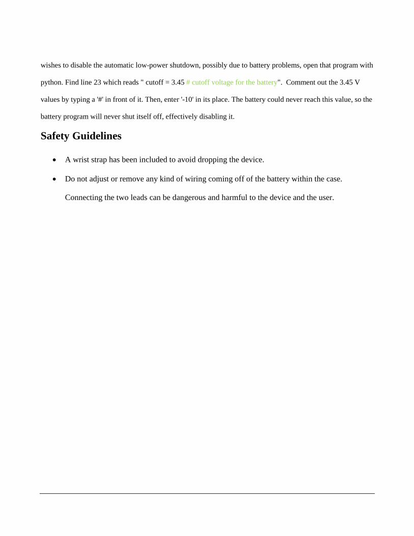
wishes to disable the automatic low-power shutdown, possibly due to battery problems, open that program with
python. Find line 23 which reads " cutoff = 3.45 # cutoff voltage for the battery". Comment out the 3.45 V
values by typing a '#' in front of it. Then, enter '-10' in its place. The battery could never reach this value, so the
battery program will never shut itself off, effectively disabling it.
Safety Guidelines
• A wrist strap has been included to avoid dropping the device.
• Do not adjust or remove any kind of wiring coming off of the battery within the case.
Connecting the two leads can be dangerous and harmful to the device and the user.

Appendix O: Bibliography
"4820ISF-SERKITAE - Honeywell 4820i Industrial Cordless 2D Image Scanner." POS Global. Web. 18 Nov. 2014. <http://www.posglobal.com/4820ISF-SERKITAE.html>.
"A16642BSNUN01: CipherLab 1664 Pocket Bluetooth Bar Code Scanner." Web. 30 Oct. 2014. <http://www.barcodegiant.com/cipherlab/part-a16642bsnun01.htm?aw&adtype=pla&kpid=165284&gclid=CLT247iu1cECFZSPfgoddTEAyQ>.
Atteberry, Jonathan. "How 2-D Bar Codes Work" 03 March 2011. HowStuffWorks.com. <http://science.howstuffworks.com/innovation/repurposed-inventions/2d-barcodes.htm> 20 October 2014.
Biris, Alexandru S. “Multi-level anticounterfeit, security and detedtion taggant.” Patent US 20100050901 A1. 4 March 2010.
Brain, Marshall. "How UPC Bar Codes Work" 01 April 2000. HowStuffWorks.com. <http://electronics.howstuffworks.com/gadgets/high-tech-gadgets/upc.htm> 16 October 2014.
Brown, Jeff. "ZBar Bar Code Reader." ZBar Bar Code Reader. Web. 20 Oct. 2014. <http://zbar.sourceforge.net/>.
Burke, Harry. Automating Management Information Systems. New York: Van Nostrand Reinhold, 1990.
"Cordless Hand Scanner 7Xi Readers from Socket." Planet Barcode. Web. 18 Nov. 2014. <http://www.barcodeplanet.com/socket/chs-7xi.htm?aw&adpos=1t2&gclid=CPT3hrDKg8ICFYpgfgodB3oA0A>.
"Datalogic GD4430-BK GD4430 Gryphon Barcode Scanner Only." Newegg. Web. 30 Oct. 2014. <http://www.newegg.com/Product/Product.aspx?Item=N82E16838129173&nm_mc=KNC-GoogleAdwords-PC&cm_mmc=KNC-GoogleAdwords-PC-_-pla-_-Barcode Scanner-_-N82E16838129173&gclid=CPCD5Mmt1cECFU1hfgodKroAfg>.
"EA11 Standard-Range 2D Imager." Intermec OEM Products: Scan Engines: EA11. Web. 20 Oct. 2014. <http://www.intermec.com/products/scanea11/index.aspx>
Eick Ben. BrandWatch Technologies. San Luis Obispo, CA. 9 October 2014. Conference Call.
Kaish, Norman. “Method for remote detection of volatile taggant.” Patent US 6025200 A. 15 February 2000.
"Honeywell Xenon 1902." Barcode Giant. Web. 18 Nov. 2014. <http://www.barcodegiant.com/honeywell/part-1902gsr-2.htm?aw&adtype=pla&kpid=86415&gclid=CP3Z7YLLg8ICFYZefgodQloAvw>
Hossein Maleki. “ Thermal Properties of Lithium‐Ion Battery and Components.” J. Electrochem. Soc. 1999 146(3): 947-954;; <http://jes.ecsdl.org/content/146/3/947.abstract#cited-by>
“How a Barcode Reader Works” 2014. TALtech.com. <http://www.taltech.com/barcodesoftware/articles/how_barcode_reader_works> Web. 20 October 2014.
"Intermec SR61BHP 2D." Barcode Giant. Web. 18 Nov. 2014. <http://www.barcodegiant.com/intermec/part-sr61bhp-002.htm?aw&adtype=pla&kpid=188083&gclid=COeBg9zLg8ICFZNhfgodUrgAlA>.
" LS3578-FZ20005WR: Symbol LS 3578 FZ Bar Code Scanner." Barcode Giant. Web. 30 Oct. 2014. <http://www.barcodegiant.com/symbol/part-ls3578-fz20005wr.htm?aw&adtype=pla&kpid=27732&gclid=CKmGkOys1cECFZNbfgodXkEAbw>.
"Motorola CS3070-SR10007WW CS3070 Handheld Bar Code Reader – USB Batch and Bluetooth." Newegg. Web. 30 Oct. 2014. <http://www.newegg.com/Product/Product.aspx?Item=N82E16838209130&nm_mc=KNC-GoogleAdwords-PC&cm_mmc=KNC-GoogleAdwords-PC-_-pla-_-Barcode Scanner-_-N82E16838209130&gclid=CIfktZGs1cECFQiRfgodmZoAjw>.
"Raspberry Pi." Raspberry Pi Home Comments. Web. 20 Oct. 2014. <http://www.raspberrypi.org>
Sentell, Jason. “Barcode Scanners: How Do They Work?” 2014. waspbarcode.com. <http://www.waspbarcode.com/buzz/how-barcode-scanners-work/> Web. 20 October 2014.
"SG20B2D-001: Intermec SG20 Series Bar Code Scanner INT-SG20B2D001." Barcode Giant. Web. 30 Oct. 2014. <http://www.barcodegiant.com/intermec/part-sg20b2d-001.htm?aw&adtype=pla&kpid=222992&gclid=CO3a9YWu1cECFRGBfgod07gAEA>.
"Symbol LS 2208 LS2208-SR20007R-NA: Symbol LS 2208 Bar Code Scanner." Barcode Giant. Web. 30 Oct. 2014. <http://www.barcodegiant.com/symbol/part-ls2208-sr20007r-na.htm?aw&adtype=pla&kpid=216851&gclid=CImgpsur1cECFYKVfgod3zwASA>.
"Wasp CCD Scanner 633808091002: Wasp CCD Scanner Bar Code Scanner." Barcode Giant. Web. 30 Oct. 2014. <http://www.barcodegiant.com/wasp/part-633808091002.htm?aw&adtype=pla&kpid=8952&gclid=CK28-IKr1cECFZKCfgodkkgAXw>.
"WHAT IS ARDUINO?" Arduino. Web. 20 Oct. 2014. <http://www.arduino.cc/>
"Where Would We Be Without Humble Barcode Labels?" Barcode Labels. Web. 20 Oct. 2014. <http://www.lightninglabels.com/articles/best-of-the-lightning-labels-blog.htm>
Yamauchi, Tsuyoshi. “Taggant particle group, anti-counterfeit ink comprising same, anti-counterfeit toner, anti-counterfeit sheet, and anti-counterfeit medium.” Patent EP2650141 A1. 16 October 2013.
Zhang, David. “Covert IR Optical Taggants Enhance Identification.” Photonics.com. <http://www.photonics.com/Article.aspx?AID=55844> 20 October 2014.

“Camera Module Setup” Raspberry PI. Web. 12 Nov. 2014. <http://www.raspberrypi.org/help/camera-module-setup/> Jones, Dave. “take images in a short time using the Raspberry Pi camera module” StackExchange. Web. 12 Nov. 2014. <http://raspberrypi.stackexchange.com/a/22110> “Xenon 1900” BarcodesInc. Web. 12 Nov. 2014. <http://www.barcodesinc.com/pdf/Honeywell/xenon-1900.pdf > “Custom Single-Board Computer Costs.” Message to John Ridgely. 29 Jan. 2015. E-mail.