ipv6 home automation - diva - simple search
TRANSCRIPT

Bachelor of Science ThesisStockholm, Sweden 2009
TRITA-ICT-EX-2009:28
T H O R H Å D É N
IPv6 Home Automation
K T H I n f o r m a t i o n a n d
C o m m u n i c a t i o n T e c h n o l o g y

IPv6 Home AutomationThor Hådén
June 2009
Bachelor's thesis
Mentor and examiner: Prof. Gerald Q. Maguire Jr
School of Information and Communication Technology
Royal Institute of Technology (KTH)

Abstract Home automation is the systematic controlling and monitoring of everyday home devices such as
lighting, heating, window blinds and appliances (both white goods and home electronics). This report describes how to control and monitor home appliances over IPv6 by using existing home automation hardware and an Internet connected gateway.
There are many commercial home automation systems available. However, these are often proprietary and/or designed for limited use. This project seeks to pave the way for IP-enabling home appliances, making such devices part of the Internet. Therefore, these devices can individually be controlled both from within the home and remotely. Internet enabling each of these devices eliminates the need for special Internet connected control units, simplifying home automation and hopefully giving yet another incentive to deploy IPv6 on a larger scale. The practical goal of this project has been to create a virtual, but practically usable, IPv6 home automation system. This has been done using existing simple home automation hardware tied to a gateway relaying uniquely addressed IPv6 command messages to the appropriate device. This gateway's only function will be to translate IPv6 commands to whatever interface the device being controlled is using (this includes translating to and from the appropriate link and physical layers). Using this platform, new applications can be created by enabling the devices to interact without relying on a central control node. The report also describes the basic design ideas of a computer connected interface to also relay information from the home automation system to the Internet.
SammanfattningHemautomation handlar om att styra och övervaka vanliga funktioner i hemmet såsom belysning,
värme, persienner samt apparater såsom vitvaror och hemelektronik. Denna rapport beskriver hur man kan styra och övervaka sådana apparater över IPv6 genom att använda existerande hemautomationssystem och en internetansluten gateway.
Det finns många tillgängliga hemautomationssystem men dessa är ofta tillverkarspecifika och/eller bara designade för väldigt specifika syften. Syftet med detta projekt är att bana väg för att få apparater i hemmet att kommunicera via IP och göra dem internetanslutna. På så sätt kan apparaterna styras både inom hemmet men även från andra platser. Genom att göra varje apparat internetansluten krävs ingen central internetansluten styrenhet, vilket skulle göra hemautomation enklare och bidra med ytterligare en bra anledning att implementera IPv6 på större skala. Målet för detta projekt har varit att skapa en virtuell, användbar prototyp av ett hemautomationssystem för IPv6. Detta har gjorts genom att använda existerande hårdvara för hemautomation och en PC-baserad gateway som översätter kontrollkommandon från IPv6 till det hemautomationssystem som används. Detta innebär att överföra data mellan olika länk- och fysiska lager. Genom att använda denna plattform kan man skapa nya applikationer där apparaterna kommunicerar mellan varandra utan att förlita sig på en central styrenhet. Denna rapport beskriver också grunderna för hur ett datorgränssnitt kan överföra information från anslutna apparater i hemmet till Internet.
i

Contents
1 Introduction.......................................................................................................................................1 1.1 Report summary.........................................................................................................................1 1.2 About the text.............................................................................................................................1 1.3 Course schedule.........................................................................................................................2
2 Introduction to home automation....................................................................................................3 2.1 Simplex home automation systems...........................................................................................3 2.2 Networked home automation systems.....................................................................................4 2.3 X10 Hybrid home automation systems....................................................................................5 2.4 IR systems.................................................................................................................................5
3 Home automation software..............................................................................................................6 3.1 Function....................................................................................................................................6
4 Internet enabling devices..................................................................................................................7 4.1 Adding IP hardware to devices..................................................................................................7 4.2 Using an Internet gateway........................................................................................................7
5 Creating an IPv6 to NEXA gateway..................................................................................................8 5.1 Hardware...................................................................................................................................8 5.2 Software....................................................................................................................................9 5.3 Networking ...............................................................................................................................9 5.4 Basic program flow...................................................................................................................9
5.4.1 Client software.................................................................................................................10 5.5 Convenience features...............................................................................................................11
5.5.1 Configuration file..............................................................................................................11 5.5.2 Logging.............................................................................................................................11
5.6 Experiments with the gateway................................................................................................12 6 Designing a receiver........................................................................................................................13
6.1 Basic design.............................................................................................................................13 6.2 RWS-371-6 radio receiver module..........................................................................................14
6.2.1 Analog output voltage level..............................................................................................14 6.2.2 Oscillations in the circuit.................................................................................................16
6.3 Atmel Attiny45 microcontroller..............................................................................................17 6.3.1 Design principles..............................................................................................................17 6.3.2 Programming the ATtiny45.............................................................................................17 6.3.3 Building a test circuit......................................................................................................18 6.3.4 Limitations of the programmer.......................................................................................18
6.4 Parallel port interface..............................................................................................................19 6.4.1 The parallel port hardware..............................................................................................19 6.4.2 Parallel port sampling software.......................................................................................19 6.4.3 Parallel port test results..................................................................................................20
6.5 The WASA Board.....................................................................................................................21 6.5.1 Features............................................................................................................................21 6.5.2 Sampling by using AT-commands..................................................................................22 6.5.3 First test result................................................................................................................23 6.5.4 Reprogramming the WASA board..................................................................................23 6.5.5 Changing the baud rate...................................................................................................23 6.5.6 Adding a fast sampling function to the WASA board.....................................................24 6.5.7 Further sampling function development ideas...............................................................25
6.6 Bit error issues........................................................................................................................25 6.7 Receiver interface software ideas............................................................................................26
6.7.1 Decoding algorithm requirements..................................................................................26 7 Protocols.........................................................................................................................................28
7.1 NEXA home automation protocol...........................................................................................28 7.1.1 Radio transmission..........................................................................................................28
ii

7.1.2 Bit encoding.....................................................................................................................28 7.1.3 Addressing.......................................................................................................................28 7.1.4 Commands.......................................................................................................................29 7.1.5 Stop symbol......................................................................................................................29 7.1.6 Verifying the reverse engineered protocol.......................................................................29
7.2 Temperature sensor 36-2881..................................................................................................30 7.2.1 Radio transmissions........................................................................................................30
8 Areas to explore further..................................................................................................................32 8.1 Microcontroller decoding........................................................................................................32 8.2 IR capabilities.........................................................................................................................32 8.3 Client programs......................................................................................................................32 8.4 Defining messages for use with this gateway.........................................................................32 8.5 Multiple IPv6 addresses for auto-configuration.....................................................................33
9 Results............................................................................................................................................34 10 Conclusion....................................................................................................................................35
iii

Glossary
ADC Analog to Digital Converter. A circuit that measures an analog voltage and outputs a numeric representation of the measured voltage level.
AM Amplitude modulation, binary bits are transmitted as radio pulses of a certain frequency at a certain amplitude.
Appliance Common electric household device or machinery.
Bit-banging A technique of using software for sending serial data on any data input/output pin without the need for special hardware.
Duplex Two-way communication where devices both have transmitting and receiving capabilities and information can flow both directions, but not necessarily simultaneously.
Gateway A device relaying data communication messages from one system to another.
GUI Graphical User Interface.
HVAC Heating, Ventilation, and Air Conditioning. The field of indoor climate control.
I2C Inter-Integrated Circuit. A synchronous serial bus used by integrated circuits.
IPv4 Internet Protocol version 4. This version supports a 32 bit address.
IPv6 Internet Protocol version 6. This version supports a 128 bit address.
IR Infrared light, invisible to the naked eye.
NAT Network Address Translation, a technique of attaching multiple computers to the Internet using one or more public IP address.
NEXA An inexpensive simplex home automation system.
PDA Personal Digital Assistant. Typically implemented as a palmtop mini computer , often with touchscreen.
RF Radio frequency.
Simplex One-way communication where devices are either receivers or transmitters and information flows in only one direction.
TCP Transmission Control Protocol. The most common transport protocol used on the Internet. Uses acknowledgements and retransmissions to make packet transmission reliable.
Transceiver A device capable of both transmitting and receiving data.
WLAN Wireless Local Area Network. Quite often such equipment follows the IEEE 802.11 standard. The commercial name for such interoperable device is "WiFi".
X10 Wired or wireless home automation system.
Z-Wave A networked home automation system.
ZigBee A networked home automation system.
iv

1 Introduction
The purpose of this bachelor's project is to develop a system for controlling common home electrical devices via the Internet using IPv6 to enable direct control, rather than requiring a home gateway. This topic was suggested by Prof. Gerald Q. Maguire Jr. as he was interested in what could be done by connecting simple home automation systems directly to the Internet. I was interested in similar things, thus I chose this as my thesis project.
Commonly, home automation software gives the user access to an interface to the home automation system by attaching a home automation computer to the Internet. The purpose of this thesis is to give all devices their own Internet address, thus making them individually connected to the Internet. The goal was to create a working system capable of relaying commands from the Internet to home automation devices, and also to relay information from different devices to the Internet. By using inexpensive home automation devices using a common radio transmission protocol I have investigated how to connect these devices to the Internet and both receive and send data.
This is a suitable bachelors thesis project as it incorporates basic computer science, wireless communication, internetworking, and basic software and hardware design. The goal of the project is to both create a functional prototype and to inspire others to continue or improve upon my work. Thus this thesis both documents what I have done in the course of this project and provides a suitable basis for future work.
1.1 Report summary
The report begins, in chapter 2, with background information to introduce to the reader what home automation is, what home automation systems are available, and the limitations of these current systems. Following this, chapter 3 describes the main function of most home automation computer programs, their benefits, and limitations. As home automation systems today are typically not connected to the Internet, chapter 4 describes several different ways to make home appliances a part of the Internet, both by adding IP hardware to unconnected devices or by building a software gateway for existing hardware systems. The approach of using a software gateway is the main focus of this project and is described in chapter 5. The software gateway uses existing commodity hardware to forward commands from the Internet to wireless devices that are part of the home automation system. Chapter 6 describes the design of a radio receiver interface for this gateway. A receiver interface allows the gateway to receive information from home automation systems and forward this to hosts on the Internet. Chapter 7 gives a detailed description of the home automation protocols used in this project. The thesis concludes with two chapters that summarizes the results of this thesis project and suggests some future work that should be done.
1.2 About the text
This report is intended for my mentor and examiner, peer students, and anyone interested in the subject. It is assumed the reader has a fair knowledge of computer communication, programming, and basic electronics. The English language was chosen to make the information available to a larger audience and not just Swedish speakers.
1

1.3 Course schedule
The work in this project has followed the schedule of the course IK150X. The project started on the 16th of March 2009 and the date for final oral presentation of the thesis was scheduled on June 1st. During this time there were scheduled classes about how to write technical reports. In these classes the work was reviewed by peer students and Richard Nordberg, who was teaching the writing classes.
2

2 Introduction to home automation
Home automation, or the idea of smart homes, is the controlling and monitoring of home appliances in a unified system. These include lighting, heating, and even home electronics. Home automation is closely related to (industrial) building automation where lighting, climate control (HVAC: Heating, Ventilation, and Air Conditioning), and security systems are integrated for central and/or automated control. Building automation often focuses on the automation of large commercial buildings. In contrast, home automation focuses more on comfort and entertainment, but both HVAC and security can be (and often are) part of a smart home.
There are many different types of home automation systems available. These systems are typically designed and purchased for different purposes. In fact, one of the major problems in the area is that these different systems are neither interoperable nor interconnected. These systems range from simple remote controlled light switches to fully integrated and networked devices controlling all appliances in an entire building. From a technical point of view these systems can be divided into two main groups differing in complexity (simple systems versus networked systems, see sections 2.1 and 2.2). Infrared remote controls, commonly used in home entertainment systems, can also be a part of a home automation system (these are covered in section 2.4).
2.1 Simplex home automation systems
Simple home automation systems often utilize inexpensive RF (radio frequency) controlled devices that communicate only one-way (simplex). The simplest (and most common) devices are remote controllers that switch individual power outlets on or off. These are mainly intended for lights, see figure 1. There are also weather stations using the same technique to transmit temperature readings from outdoor sensors at certain intervals to an indoor weather display. Similar to the switched outlets there are remote controlled doorbell systems, in which the door bell button and the chime are connected wirelessly.
Technically, one remote transmitter can control a small number of receivers, but generally neither the devices nor controls are networked. Since the remote control and the receiving device communicate directly, the system requires that the transmitter be within range of the receiver. If additional range is needed, there are repeaters that simply retransmit the command with more power. The specified range is often less than 30 meters in open air, as the controls are designed for use in the same room or an adjacent room.
The radio signals themselves are often simple, AM modulated signals that use license-free radio bands such as the 433 MHz band. The messages generally consist of a binary address and a command. Unlike most communication systems, the addresses are often hard coded into the transmitters, rather than the receivers. Many of the receivers can be programmed or “taught” to listen for one or more specific transmitter codes, typically
3
Figure 1: Simple remote switched light. One-way only.

up to five different codes. For some receivers the listening code is manually set using a switch on the device. The receiver will only respond to commands sent to its specific address.
Via the programming or “learning” feature, many receivers can be configured to respond to a single remote control. Similarly, a receiver can be configured to respond to several different remote controls. This makes it possible to perform many tasks with the push of a single button on the remote control. Additionally, a single receiver, for instance a light, can be operated from different rooms in the house using different remote controls.
These systems are popular for home automation since they are very inexpensive and often sold in sets consisting of a remote control and a number of receivers that plug directly into an electrical outlet. These sets often cost just a few hundred Swedish kronor and additional receivers and transmitters with different functions can be purchased separately.
There are many brands and manufacturers available in stores. Some of these products are generic no-name systems which may or may not be compatible with other brands. However, there are two popular systems that offer a wide range of compatible devices, Clas Ohlson markets the Waveman system and the NEXA [7] system is available from a number of retailers.
Since many of these systems are so technically similar they are sometimes compatible out of the box, but the simplicity of the radio protocols also makes the signals possible to sniff with a receiver connected to a computer (more on this in chapter 6). Simplicity suggested the method examined in this thesis, i.e. creating a generic gateway that can be programmed to control many different kinds of devices. It also suggested that a software based receiver might also be useful - see section 6.7.
The NEXA system has been chosen as the main home automation system used for this thesis. It is described in more detail in chapter 7.
2.2 Networked home automation systems
The more complex home automation systems feature a built-in two-way (duplex) networking scheme that can integrate many devices in a home or building. Examples of such systems are Z-Wave [1], ZigBee [2], and the popular X10 [5]. X10 will be discussed further in section 2.3. These systems rely on mesh networking, i.e. devices in the network can be used as repeaters or even routers, extending the range to cover large buildings (see figure 2). Since these systems support two-way communication the devices are more capable of performing meaningful tasks. This two-way communication allows devices to respond to commands and to send send unsolicited messages such as alarms and warnings.
4
Figure 2: Networked system where devices are used as repeaters.

These are generally commercial systems with devices available through home automation retailers. To be certified to design and manufacture devices compatible with these two systems, it is necessary to be a member of the Z-Wave or ZigBee Alliances. Z-Wave has been available for several years and there are lots of compatible devices available.
These more advanced systems can be connected to the Internet and can be controlled remotely. This is done by attaching an Internet gateway to the home automation network. In most implementations the user can log on to the gateway via the Internet and control and monitor devices on the home automation network. This is usually done with a gateway computer, providing a web interface where the user can view device information and send commands to the devices.
2.3 X10 Hybrid home automation systems
The X10 system is a hybrid between simplex systems and networked systems. It started as a very simple system that has seen a lot of development over the years. It now provides features common to the more expensive systems, but at a price closer to simplex systems. It was first developed in 1975 as a wired system using power lines as the transmission medium. It has since then been expanded to also support radio communication. The system was designed for simplex communication, but some newer devices support two-way communication. X10 is fundamentally as simple as the simplex systems described in section 2.1. With its extended capabilities it has become very popular and widespread, especially in North America. There is a plethora of X10 enabled devices including computer interfaces enabling the systems to be remotely controlled.
2.4 IR systems
In practice a fourth group of systems includes all the home electronics that use IR (infrared) remote controls. As home theater systems have become mainstream, it has become increasingly popular to automate home electronics. A typical home theater system consists of many devices that need to be operated, thus universal remote controls are commonplace. There are many universal remote controls available that can learn IR codes from other remote controls, thus replacing them. Infrared remote controls are very similar in function to the simpler home automation systems and some home automation appliances even use IR instead of RF. The communication is almost always simplex and it is very simple to sniff the communications to learn the command sequence, then generate these via a computer. There are also programs for mobile phones and Personal Digital Assistants (PDAs) that have an on board IR transmitter, to act as an IR remote control.
Some attempts have been made to integrate IR and RF systems by adding an RF transmitter in universal remote controls. Today these RF transmitters do not work with the majority of wireless home automation systems and can only be fully integrated in such systems using a gateway.
5

3 Home automation software
While studying the field of home automation I have found many computer programs that interact with different home automation systems. Home-automation.org maintains an excellent list of home automation software [4]. However, in order for a computer program to control devices, the computer requires an interface to the home automation system used. This is commonly a radio transmitter or transceiver attached via a USB or other serial interface to the computer.
3.1 Function
The main function of the home automation programs is to provide centralized control of the system. The computer running the program communicates with all devices, thus sensors can be read and devices can be controlled. However, the purpose of the home automation computer is not only controlling devices, but to provide additional functionality such as data logging and task scheduling. These functions are what makes a home “smart”. Sensors and scheduling can be used to control the home's temperature and lighting by reacting to weather, amount of sunlight, and time of day. A home owner can save money by switching off the ventilation and heat when he or she is away. These programs often have a graphical user interface (GUI) that provides the user with a clear and user friendly view of the system's functions and the status of the various sensors.
It is very common for these systems to be remotely operated via the Internet. The user can access the GUI of the program in order to control and monitor devices. The benefits of remote access to the home automation system are many. For example, this offers convenience as the user might turn on devices such as the dishwasher or oven from work and come home to clean dishes and an oven ready for cooking. For energy saving the user can manually switch off unused devices and for security the user can check if the doors are locked or if someone forgot to switch the coffee pot off.
The usual way of doing this is via a web server running on the home automation computer to provide a web page that acts as the GUI. Using their device's web browser, the user can use the GUI to invoke the different functions of the program. These in turn control the devices in the home automation system. Technically one can argue that the computer running the home automation software is connected to the Internet, but the devices themselves are not connected to the Internet as the do not have their own Internet address. Figure 3 shows an example of a typical home automation program controlling a NEXA system.
6
Figure 3: The user can either access the GUI on a local home automation or via the Internet using a GUI.

4 Internet enabling devices
Given the benefits of being able to control and monitor all sorts of devices remotely it would be interesting to connect all of these devices directly to the Internet, giving each device its own Internet address. This would enable software developers to make full use of the capabilities of each device, rather than being restricted to the functions that are implemented by the specific home automation system that they have used. Today, many home electronic devices such as TVs, stereos, Blu-ray players, and even refrigerators have some form of Internet connection, but lack the software to make them fully controllable online. Simpler devices such as light sockets do not have Internet connectivity.
4.1 Adding IP hardware to devices
IP-enabling devices individually would require the devices to have computing hardware capable of running an IP stack. Giving the devices sufficient processing power and adding the ability to communicate, will make the devices “smarter”. Instead of just having the minimum electronics for obeying a command, the devices could decide for themselves what commands to obey. In addition to obeying commands, the device may answer questions and sending unsolicited messages or requests. As a result, the intelligence can be moved from central control devices such as computer servers to the actual devices themselves. For physical communication, Internet devices could also use regular data networks, such as WLAN as these are increasingly available in homes. For stationary devices, a wired network would be an alternative.
The technical benefits of embedding such circuits into everyday appliances would be many, but for simple appliances this solution is not economically viable. Since the cost of the added hardware would surpass the cost of the device itself, this approach would initially be reserved for more expensive equipment such as home electronics and high-end white goods. Given the declining cost for integrated circuits, eventually nearly all devices will be able to both compute and communicate.
4.2 Using an Internet gateway
To make home devices controllable via the Internet, a gateway can be used. Today's home automation software only provides a user interface to the system, but does not provide the ability to communicate with the devices themselves. A home automation gateway would simply relay information between the IP network and the end devices. Each end device will have its own IP address. The gateway software can be used to receive sensor data and to pass commands along these to IP-capable devices. Such a gateway solution changes the way home devices are controlled, since the devices (both actuators and sensors) become part of the Internet. Note that such a gateway is straight-forward for networks such as ZigBee by running 6LowPAN [27].
This approach is currently more cost effective than directly connecting the devices to the Internet, since it requires less hardware capabilities of the devices themselves. Instead the gateway performs the processing necessary to convert between the device's communication protocol and some external IP based protocol. This approach has been chosen to control home automation devices in this thesis.
7

5 Creating an IPv6 to NEXA gateway
The main purpose of this thesis is to create a gateway to control simple home automation hardware from the internet. In this case I have chosen the NEXA system as the main home automation protocol. I have created a home automation gateway that relays information between the Internet and the NEXA home automation system. The purpose of this gateway is to emulate the behavior of Internet enabled devices and to understand how such a gateway allows the use of existing non-networked devices. A gateway such as this requires an Internet connection and an interface to the NEXA system.
5.1 Hardware
The gateway physically consists of a computer with a USB connected radio interface. The computer is a Compaq Evo 610 laptop running the Linux operating system (details in section 5.2). The radio interface is a Telldus Tellstick [3]. The Tellstick (shown in figure 4) is a USB attached transmitter operating at 433.92 MHz as a radio remote control. It can be programmed to control a wide variety of devices. The hardware is limited in frequency, but can provide the modulation common in simple home automation protocols.
To test the gateway it will be used for controlling two switched outlets using the NEXA protocol, which is described in more detail in section 7.1. A NEXA remote controller and a NEXA radio controlled outlet are shown in figure 5.
8
Figure 4: The Telldus Tellstick.
Figure 5: A NEXA remote controller and a NEXA remote controlled outlet.

5.2 Software
The gateway software is written in the Python scripting language [14]. The reasons for choosing this language are that it is very simple and easy to use, making it excellent for rapid code development. Since it is a scripting language it does not need to be compiled before executing the code.
The operating system of the gateway computer is Linux. I chose the Ubuntu Desktop distribution[15] for the sake of simplicity. Ubuntu comes with many useful tools and even a built-in Python interpreter. The Advanced Packaging Tool makes it simple to add additional software.
5.3 Networking
The gateway software is written to utilize IPv6. IPv6 was selected because the limited address space of IPv4 will not be suitable in situations such as large buildings where thousands of devices need to be addressed (keeping in mind the goal of making it seem as if the devices are directly connected - hence globally addressable – via the Internet). With minimal alterations of the code the gateway software could be made to use IPv4. However, this would limit the ability to address all of the devices. During development only link local IPv6 addresses are used. However, if there were an IPv6 gateway on the local area network the home automation gateway could utilize the IPv6's autoconfiguration function to learn the global prefix.
The gateway uses the computer's Ethernet interface for Internet connectivity. This is done to simplify the development process as a wired Ethernet does not need an IPv6 capable access point to communicate with clients. The software is designed so that it can be used with either a wired or wireless connection.
TCP (Transmission Control Protocol) will be used as the transport protocol since it provides reliable connections. This is important when controlling a device in another building, as it is otherwise impossible to determine if the command sent has been received by the gateway.
All development has been done on a private wired network. During development the TCP port number used by the gateway software has been 1981 for no other reason than that it is my birth year. However, this is a IANA registered port [26] and should not be used on the Internet.
The proper way to register a port for use on the Internet is to apply for a registered port number from IANA. Using a properly registered port avoids the problems encountered if two services on the same computer use the same port number.
5.4 Basic program flow
The main function of the gateway is to relay information from the Internet domain to the home automation system. To enable the computer to act as a relay for multiple devices, the computer is configured with multiple IPv6 addresses. This is done by adding additional IPv6 addresses to the desired network using the ifconfig command.
The device's IPv6 addresses are manually assigned with the the computer's own IPv6 address as their base. In this prototype the addresses that are assigned to home automation devices are the base address + n, n being the count of each device added. For example, if the base address of the interface ends with 00, device number 1 will have an IPv6 address ending in 01. The IPv6 address of device number 2 will end in 02 and so on.
9

For use on the Internet these addresses would have to be assigned according to the subnet to which the gateway is connected. If IPv6 autoconfiguration is to be used, then some means of having multiple IPv6 addresses associated with this gateway will be necessary. Details on this is lie outside the scope of the report.
Each additionally assigned IPv6 address corresponds to a device in the home automation system. This mapping information forms an address mapping table. More on the addressing in the NEXA protocol in section 7.1.3.
At program startup one process thread is created per device in the home automation system. Each thread opens a TCP server socket for one of the IPv6 addresses in the configuration. A configuration file is used to define the mapping between the IPv6 addresses and the actual device (see section 5.5.1). When a TCP connection is made by a remote client, and a TCP segment is received on one of the device's address, the gateway examines the segment, determines which command was received and sends the appropriate command to the NEXA device in question (see figure 6). This approach makes it possible to use any home automation protocol compatible with the radio transmitter, at the cost of writing a suitable translation module for each home automation protocol used.
When a command is relayed to the radio interface the gateway will consider the command successful and assume that the command has been received correctly by the device. Since the NEXA protocol does not support two-way communication, an acknowledgement will not be sent by the device. Even if the NEXA device were able to send an acknowledgement the Tellstick does not function as a receiver. This is a limitation of the simplex home automation system's hardware. However, the gateway software will respond to the controlling host by sending a reply segment, indicating to the user that the command was received and processed by the gateway. By adding a receiver to the gateway it would be able to receive acknowledgements, but the device being controlled must also be able to transmit the acknowledgements (see chapter 6 for more information about designing a receiver).
A user can also find out if a device was switched on or off by the gateway by sending a poll message. Unfortunately, for simplex devices the gateway can not determine the device's actual status, but the gateway will respond with the last command which it executed for this device. The source code of the gateway software can be found in Appendix I.
5.4.1 Client softwareTo be able to test the gateway software I also created a very simple client program. It
is also written in the Python programming language. The client program simply opens a TCP connection to a specified IPv6 address and sends a TCP segment containing a command. After sending the command the client program awaits a TCP segment in
10
Figure 6: The gateway listens to multiple IPv6 addresses and relays commands to the corresponding NEXA device.

return. This return segment is the reply sent by the gateway software to indicating to the user the status of the device. After receiving the reply the TCP connection is closed. All commands and replies in this initial configuration are terminated with a newline character ('\n'). The source code of the client program can be found Appendix III.
5.5 Convenience features
To make configuration and operation of the gateway software simpler, a few features were added. These features include a configuration file to associate the IPv6 addresses with a device, its protocol and its address; and logging to be able to have a history of what commands were received and when.
5.5.1 Configuration fileTo make configuration of the gateway software simpler, all device configuration is
stored in a text file called devices, stored in the same directory as the main Python code. In this file, each row represents one device. For each device the following information is stored as text strings separated by tabs:
• In use flag (1 or 0 determines if the device is active or not)
• IPv6 address
• Protocol name
• House address
• Unit address
At program startup this information is read from the file and stored in the computer's memory. To add new information or change information about devices, the gateway software needs to be restarted after changes have been made in the devices file. The contents of an example configuration file can be found in Appendix II.A.
5.5.2 LoggingEvery time a command is received and carried out, an entry is created in a log file.
This log file is also stored in the same directory as the main Python code. Each entry is written as a new line and contains the following information separated by tabs:
• Date and time
• Controlling host IPv6 address
• Receiving device house address
• Receiving device unit address
• Command sent
An example log file can be found in Appendix II.B.
11

5.6 Experiments with the gateway
Configuring the software using the configuration file shown in Appendix II.B the test program was executed on a Windows computer with the following commands. The last line of each program execution is the reply received from the gateway.
>python client.py fe80::202:a5ff:fec2:7fb8 onConnecting to fe80::202:a5ff:fec2:7fb8Sending command onfe80::202:a5ff:fec2:7fb8 says light is on
>python client.py fe80::202:a5ff:fec2:7fb8 offConnecting to fe80::202:a5ff:fec2:7fb8Sending command offfe80::202:a5ff:fec2:7fb8 says light is off
>python client.py fe80::202:a5ff:fec2:7fb9 onConnecting to fe80::202:a5ff:fec2:7fb9Sending command onfe80::202:a5ff:fec2:7fb9 says light is on
>python client.py fe80::202:a5ff:fec2:7fb9 offConnecting to fe80::202:a5ff:fec2:7fb9Sending command offfe80::202:a5ff:fec2:7fb9 says light is off
>python client.py fe80::202:a5ff:fec2:7fb9 pollConnecting to fe80::202:a5ff:fec2:7fb9Sending command pollfe80::202:a5ff:fec2:7fb9 says light is off
The gateway worked as expected, it switched the lights associated with these IPv6 addresses on, then off as commanded. Also, the log file showed the these events as expected:
2009-05-20 13:50:24 fe80::216:36ff:fe4c:8c71 sent A 1 on2009-05-20 13:50:28 fe80::216:36ff:fe4c:8c71 sent A 1 off2009-05-20 13:50:32 fe80::216:36ff:fe4c:8c71 sent A 2 on2009-05-20 13:50:36 fe80::216:36ff:fe4c:8c71 sent A 2 off2009-05-20 13:50:39 fe80::216:36ff:fe4c:8c71 sent A 2 poll
12

6 Designing a receiver
While the Tellstick equipped gateway works very well for controlling units remotely, the lack of receiving capabilities significantly limits its usefulness. Adding a radio receiver to the gateway would enable the system to relay information in both ways. The proposed receiver is mainly intended for a remote weather sensor from Clas Ohlson (inventory number 36-2881). More details on this remote sensor are given in section 7.2. Note that a receiver compatible with the temperature sensor would also be compatible with many other protocols, such as NEXA, with the proper decoding software. The receiving capability posed a problem for the project as there were no 433MHz radio receivers available for computer use, thus one had to be created.
6.1 Basic design
Designing a 433 MHz receiver interface to a PC required two hardware elements: A radio receiver to receive the signals and a computer interface to transfer the received data to the computer for processing. Kjell&Company sells a RWS-371-6 radio module which can receive 433.92MHz signals. The challenge was to create a computer interface to take this data and convert into a suitable format for processing by an application running on a computer.
There were three basic requirements for the interface. First of all, the interface needed to be compatible with the computer. This meant using the serial RS-232 port, the parallel port, or a USB port. The later is preferable as the number of computers with RS-323 serial interfaces or parallel interfaces is decreasing.
The second requirement was that the interface needed to be fast enough for the bit rate involved. For example, the NEXA protocol operates at approximately 2857 bits per second and the temperature sensor's protocol operates at approximately 1818 bits per second (for more details about these protocols see section 7).
The third requirement was that the interface or software written for it needed to decode asynchronous serial communication, as there is no clock signal transmitted with the data.
The following sections describe the radio module used to receive the radio signal (section 6.2) and the different approaches of connecting this module to a computer. These approaches were based on the the ATtiny45 microcontroller (section 6.3), the parallel port interface (section 6.4), and the USB connected WASA board (section 6.5). For the parallel port interface and the WASA board interface I have created testing programs to retrieve the binary data to the computer. Section 6.7 describes how a decoding program for any receiver interface may be designed.
13

6.2 RWS-371-6 radio receiver module
The receiver design is based on a radio receiver module that is available in Sweden from Kjell&Company (inventory no. 88900). The receiver module is not sold under a brand name and Kjell&Company could not provide any more information about the manufacturer. There are similar radio modules available from several manufacturers, but the figures in the data sheet provided by Kjell&Company matches those of the Wenshing RWS-371-6 [25]. The Kjell&Company radio module also looks exactly like the Wenshing RWS-371-6 (the bar code sticker on the radio module's PCB, shown in figure 7, also contains the number '371', perhaps indicating the model number). Therefore, I have assumed the radio module I have used is in fact a Wenshing RWS-371-6. Note that the differences between similar radio modules from other manufacturers are minimal, their basic layout and function area identical.
The RWS-371-6 radio module can receive any AM 433.92MHz radio signals. The unit itself has one linear analog output and one digital output. This makes it capable of receiving both analog an digital data. The digital output uses TTL voltage levels where a '0' bit is 0 V and a '1' bit is +5V. The maximum data rate of this receiver is 4.8kbps which makes it compatible with the NEXA protocol, which operates at approximately 2857bps. The RWS-371-6 requires 5V to operate. Figure 7 shows the RWS-371-6 on a breadboard with 5V, ground, and a ~35 cm antenna connected. The digital and analog outputs are pin 2 and 3 respectively.
6.2.1 Analog output voltage levelInitially I performed some tests on the RWS-371-6 radio module itself and discovered
that it needed some modifications to function as required. I also found a reliability problem that was alleviated, but not solved completely, by the modification. These modifications (the addition of a pull-down resistor) are described below.
When I viewed the digital output using an oscilloscope, the output voltage spiked randomly, as shown in figure 8, even when I did not transmit any information. The digital output voltage should have been a steady 0V when idle. This indicated that the analog-to-digital converter (ADC) could not distinguish if the incoming analog signal was either high or low. I connected the oscilloscope to the analog output and discovered that the analog voltage was relatively steady at around 2.5V when idle. The analog output is shown in figure 9 on the next page.
14
Figure 7: The RWS-371-6 on a breadboard.

The logical reason for such a high voltage (+2.5V) even in the absence of an RF signal was due to the fact that this radio receiver is also intended to receive analog signals. As an AM radio cannot transmit a negative voltage, a sine wave, such as audio (which generally alternates between a negative and a positive voltage), would be clipped, removing all negative parts of the signal. Therefore the analog output voltage is biased such that the '0' level is set to be 2.5V in order to accommodate the entire signal. This is illustrated in figures 10 and 11.
To compensate for this I needed to lower the voltage at the analog output to a safer level. This would help the ADC to distinguish between high and low signal. To do this I used a pull-down resistor, causing the voltage at the analog output to drop to almost 0V when there was no RF signal. The pull-down resistor was connected between the analog output and the common ground.
15
Figure 8: Digital output with severe interference. Figure 9: Analog output at around 2.5v.
Figure 11: Sine wave with voltage biased by 2.5V.
Figure 10: Sine wave. A negative voltage can not be transmitted with AM radio.

I discovered the value of the pull-down resistor on the analog output would also affect the voltage on the digital output. The effect of this is described in more detail in section 6.4.1, where it is also described how the value of the pull-down resistor was chosen. The value I used was 12kOhm, but what is important for this section is just the fact that a pull-down resistor was required.
When a signal was received the analog output peaked at 4.89V, now the ADC functioned satisfactory, as shown in figure 12, and the digital output could be used.
6.2.2 Oscillations in the circuitDuring testing I discovered a problem with the RWS-371-6 receiver module. At times,
which to me appear to be random, the radio module's internal electronics seemed to make the analog output voltage oscillate. The frequency and amplitude of these oscillations also appeared different each time they occurred. An example of these oscillations is shown in figure 13.
I investigated the cause of this by measuring the input voltage but could not find any ground loops or other obvious causes of the oscillation. I was unable to reproduce this fault myself, as it appeared at seemingly random intervals. I tried using 5V power from both an external power supply and the gateway computer's USB port, both power sources yielded the same results.
Clearly the radio receiver did not work perfectly, and the amplitude of this interference caused the digital output to produce errors several times every second. This caused problems later in the project (described more in section 6.4).
16
Figure 12: Digital output during a transmission, showing individual bits.
Figure 13: Analog output voltage oscillation.

6.3 Atmel Attiny45 microcontroller
To connect the RWS-371-6 radio receiver module to a computer I needed a computer interface. I investigated the use of an Atmel ATtiny45 microcontroller [20]. This microcontroller is a popular choice of enthusiasts as it is very cheap, and very capable. It has six programmable input/output (IO) pins and four ADCs (Analog to Digital Converters). It has a flash memory which means that it can be programmed and reprogrammed again and again. By running a software implementation of the USB protocol [21] on the controller, the data pins can be used for USB communication with a computer. Using USB is very practical as it is a very common bus on modern computers and. The PC's host USB port also provides 5 volts to power the controller and a modest amount of additional electronics.
6.3.1 Design principlesI got my inspiration from Till Harbaum's design of a USB to I2C interface [11]. I2C is a
serial low bandwidth bus often used to communicate with simple sensors. In his design the ATtiny45 is loaded with a software implementation of the USB and I2C bus protocols. This is to enable USB access to integrated circuits designed for the I2C bus. Harbaum's design is an open source project and the source code is provided for download on Harbaum's web site [11]. I used this circuit and code as a basis for my design as I wanted USB compatibility for my receiver. However, I was not interested in communicating with I2C devices, but simply wanted to connect the RWS-371-6 receiver module to one of the data pins and sample it at a suitable rate.
6.3.2 Programming the ATtiny45In order to use the ATtiny45 microcontroller it is necessary to load a program into its
memory. For this, a microcontroller programmer is needed. A programmer is a device that writes the compiled program into the microcontroller's memory. The program is written as a serial stream of data to the controller's programming pin. There are many programmer models available from different manufacturers, but I chose to build a simple low voltage programmer myself using just a few simple parts, using plans I found at MetkuMods [13]. The circuit diagram is shown in figure 15. This programmer connects to the parallel port on a PC and requires 5V to operate. To eliminate the need for an external power supply I added a male USB-cable to the circuit board which provides 5V from the computer itself as shown in figure 16.
This simple programmer requires that the software to do most of the work. In this case I used PonyProg [22] which is a free programming application for Windows and Linux. It uses a bit-banging technique to erase and write new firmware into the microcontroller's memory.
17
Figure 14: The Atmel ATtiny45 microcontroller.

6.3.3 Building a test circuitBefore rewriting the my own software for the ATtiny45, I first set up the USB tiny I2C
circuit on a breadboard to make sure the parts and original software worked as advertised. However, it became clear that the circuit did not work as intended. When connected to a computer, the computer reported that a USB device had been connected but it malfunctioned and could not be used. As the circuit was simple it was easy to verify all the connections, and I found no errors. I concluded that the problem must be with the microcontroller. By using the PonyProg programming application I read the software on the chip and compared it to the original file provided by Harbaum. The software showed no corruption and I concluded that the error was not in the software.
6.3.4 Limitations of the programmerI found that the USB tiny I2C software required the RESET pin of the ATtiny45 to be
disabled. In the USB tiny I2C device the RESET pin is used as an input/output port for I2C communication. To do this the RSTDISBL fuse on the microcontroller needed to be blown. However, blowing the RSTDISBL fuse disables the chip to be reprogrammed using a low voltage programmer. Because of this, the PonyProg programming application does not allow the RSTDISBL fuse to be blown. Even if the PonyProg programmer had allowed RSTDISBL to be blown, I would not have been able to
18
Figure 16: The programmer made for the ATtiny45 microcontroller.
Figure 15: Programmer circuit, parallel port to the left, 8-pin IC holder to the right.

reprogram the chip with a modified version of the software.
A solution for this would of course to use a high voltage programmer, such as the STK500 [23], which is capable of reprogramming a chip with the RSTDISBL fuse blown. However, the price of such a programmer was well beyond the project's budget and ordering a programmer online could not guarantee delivery until very late in the project. Thus, the method of using the ATtiny45 was abandoned due to time and budget constraints.
6.4 Parallel port interface
As using the ATtiny45 microcontroller proved to be complex and time consuming I chose a simpler approach. This method was to use the parallel port of a computer to read the output of the radio receiver module. The advantages of this approach are that it requires almost no additional hardware, and it is very easy to write a computer program that can read data from the parallel port data pins. However, a disadvantage of this approach is that fewer and fewer computers have built-in parallel interfaces and using the parallel port is not future-proof.
6.4.1 The parallel port hardwareThe interface needed only a wire connecting the RWS-371-6 digital output to one of
the data pins on the computer's parallel port and a ground wire. I built a cable that uses data pin 9 on the parallel port as the input and pin 25 as ground. The RWS-371-6 digital output was connected to the parallel port's input pin and the and the ground wire was connected to the radio module's ground pins. I used a USB cable to power the RWS-371-6 as with the ATtiny45 programmer (see section 6.3.2).
The parallel port of the computer showed an unexpected behavior that is worth noting. Even when the data pins on the parallel port were set to be input pins there was +5V on the pins. This means that the input always registered as high unless they were grounded. Connecting the +5V input pin to the near-0V digital output of the radio receiver module resulted in a voltage higher than 0V.
As mentioned in section 6.2.1 the value of the pull-down resistor on the analog output would also affect the idle voltage on the digital output. A smaller pull-down resistor would increase the idle voltage on the digital output and vice versa. Using a smaller resistor than 12kOhm the idle level on the digital output would exceed 0.8V, which is the high limit for a '0' bit using TTL levels. When the 5V input pin was connected to the digital output of the RWS-371-6, and using a 12kOhm pull-down resistor on the analog output, the low state measured 0.73V when no transmission was received. Thus, the low state was within TTL levels and the unexpected input pin voltage level did not cause any problems.
6.4.2 Parallel port sampling softwareAlthough the main program of the gateway was written in Python I wrote the test
program for the parallel port in C. This was because the parallel port library for Python (pyparallel [24]) is still under development and currently not very useful.
The program I wrote was intended for testing the interface. The main function of the program is to sample the state of the input pin at an appropriate rate and write the result to a text file. To reduce the text file's size the program started sampling the input at startup, but did not write the results to the text file until a '1' was detected.
The program was able to sample the input pin of the parallel port at a much faster rate than required. To slow the program down I paused the program for a short time between each sample. I calculated this time by measuring the number of samples the program generated per second.
19

I determined the program's maximum sampling rate by feeding a 1.2kHz square wave to the input pin. The 1.2kHz square wave can be viewed as a data transmission of alternating 1's and 0's at 2,400 bits per second. When sampling this bit rate the program recorded approximately 45 samples per bit time slot. This corresponds to approximately 108,000 samples per second, or one sample every 9.26µs.
To accurately sample the bit rates of the wireless protocols used in this project I needed a sampling rate of a few thousand samples per second (details about these protocols are found in chapter 7). I decided to slow the program down to a tenth of the maximum speed, around 10,000 samples per second. This would be fast enough for bit rates up to around 5,000 bits per second, according to the Shannon-Nyquist sampling theorem. The Nyquist–Shannon sampling theorem states that to sample a signal accurately the sample rate must be twice that of the highest frequency of the signal.
To slow the program down I inserted a 100µs delay after each sampling command in the program's main loop. This slowed the program down to one sample every 109.26µs, or 9,152.48 samples per second.
Note that this is program was only written for initial testing purposes in a controlled environment. Basing this sampling rate (with a busy-wait loop) will have disastrous consequences if running other CPU intensive processes on the same computer. Note that running the program on another computer with different a processing speed would require recalculating the delay after sampling.
The complete source code of this program can be found in Appendix IV.
6.4.3 Parallel port test resultsUsing this program I could sample radio transmissions from both the NEXA protocol
and the weather sensor's protocol. I could review the bits in the text file directly but it was more convenient to import the data into an OpenOffice.org spreadsheet. That allowed me to display the data as a graph, similar to the screen of an oscilloscope, as showed in figure 17.
The parallel interface and software at least proved that the parallel port was a fully usable interface for the radio receiver module.
20
Figure 17: Example of a temperature sensor radio transmission sampled via the parallel port.

6.5 The WASA Board
I also designed a receiver interface for the computer using the WASA board [8]. This is a circuit board designed for teaching (see figure 18). It was developed by Prof Mark T. Smith of KTH for his Sensor Based Systems course [9]. The board already has a number of on-board sensors and a number of General Purpose Input Output (GPIO) ports.
6.5.1 FeaturesThe WASA board connects to a computer through a USB interface and emulates a
serial port. The WASA board uses 115,200 baud (symbols per second) as default. The software on the WASA board accepts AT-commands for communication. AT-commands (based upon the Hayes command set) were a system created to communicate with modems/dialers. The name AT-commands derives from the fact that all commands begin with the letters “AT” (AT is short for attention). A user can communicate directly with the WASA board using a terminal program such as Hyper Terminal on Windows or Minicom on Linux. Most programming languages also offer APIs for using serial ports.
The user, or computer program, writes a text string to the serial port output buffer which is transmitted via the computer's USB interface to the board. The main program reads the strings received from the computer and executes a chain of functions according to the characters in these strings. If the command string requests a reading from a port or sensor the WASA board retrieves the value and writes a reply to its output buffer, thus transmitting the reply back to the computer. To retrieve the reply, the computer simply reads from its input buffer where the reply is stored.
The software for the WASA board adds newline and carriage return characters to each reply to make it more readable on screen. Along with each reply an “OK” message is sent to the computer, also formatted with newline and carriage return characters.
21
Figure 18: The WASA board. The main microprocessor is located on the reverse side of the board. The wires are connected to an Input/output port (red) and ground (black).

6.5.2 Sampling by using AT-commandsTo test the WASA board's ability to sample an input port, using the default speed
115,200 baud, I connected the analog output of the RWS-371-6 receiver to the GPIO_0 pin and connected a ground wire between the two devices (see figure 19).
To be able to record the weather station transmissions, at approximately 1,800 bits per second, I needed to sample least 3600 times per second, according to the Shannon-Nyquist sampling theorem.
I wrote a simple program in Python that connects to the WASA board, and in a loop send 1,000 read requests of GPIO_0. After each request the input buffer is read and displayed on the screen. The WASA board also replies with empty lines and “OK” messages indicating that it correctly executed the commands. These were ignored.
To test the board's sampling speed, a software timing function in the program was used to measure the time it took for 1,000 samples to be gathered. This data is described in the next section.
22
Figure 19: The WASA board connected to the RWS-371-6 receiver module.

6.5.3 First test resultThe sampling program was run ten times to get an average as the time varied some at
each attempt.
Table 1: WASA board sampling times using AT-commands.
Program run Time taken (s)
1 2.915
2 2.877
3 2.927
4 2.918
5 2.965
6 2.890
7 2.888
8 2.895
9 2.919
10 2.876
Average 2.907 s (with a standard deviation of 0.0259 s)
The time it took to retrieve 1,000 samples varied from 2.876 to 2.965 seconds and the average time was 2.907 seconds with a standard deviation of 0.0259s. This corresponds to 344 samples per second.
This result proved that sending AT-command requests for each sample to the WASA board at the current serial interface speed could not deliver the sampled bit stream from the radio fast enough, or at a constant rate. In fact, this method only provided about a tenth of the required sample rate.
6.5.4 Reprogramming the WASA boardThe original software and configuration of the WASA board was not fast enough. From
looking at the source code for the WASA board, that was provided by Prof. Mark Smith on his WASA board web site [9], I discovered that the communication speed could be increased. This meant that I needed to rewrite the software running on the WASA board's main processor. I wrote and compiled the modified source code using the IAR Embedded Workbench Kickstart for MSP430 compiler [18]. The code was specifically compiled for the MPS430F2618 processor.
The IAR Embedded Workbench compiler downloaded the new software to the WASA board using a MPS430FET-UIS programmer [16]. This programmer is an interface device that connects a computer via the USB interface. It connects to the circuit board via a JTAG [19] interface. This allows the user to erase the chip's flash memory and to write new firmware to the main processor of the WASA board.
6.5.5 Changing the baud rateThe WASA board default speed for USB communication is 115,200 baud. This speed is
set by the software and can be modified. The WASA board operates at 16MHz and the during initialization the baud rate is set as 1/138 clock frequency, or 115,942 baud, which is close to 115,200. By changing the divisor from 138 to a lower value the baud rate increases. I experimented by decreasing the divisor value to ½, thus doubling the baud rate for each step.
23

To make better use of the available bandwidth I also modified the sampling functions in the software. From the reply strings I removed the superfluous newline characters. This reduced the bandwidth requirements and eliminated the need to strip these extra characters from the reply string on the computer.
At each baud rate change I ran the test program which is described in the previous section. I discovered that the communication speed increased significantly, but topped out around 1Mbaud. This resulted in approximately 2299 samples per second. The test results when running at 1Mbaud are shown in Table 2.
Table 2: WASA board sampling times using AT commands at increased baud rate.
Program run Time taken (s)
1 0.409
2 0.431
3 0.431
4 0.446
5 0.425
6 0.459
7 0.474
8 0.437
9 0.392
10 0.444
Average 0.435 s (with a standard deviation of 0.0235 s)
Even at baud rates up to 2Mbaud the performance was not improved further. I concluded that the USB communication was not the bottleneck since the actual transfer rate was much lower than the configured speed.
6.5.6 Adding a fast sampling function to the WASA boardIncreasing the WASA board's communication speed did not solve the problem with
the sample rate. The theoretical limit of 2Mbaud communication should have been enough for much higher sampling rates. The WASA board's MSP430F2618 processor should also be fast enough to deliver the data. This processor only needs 1.22 µs to sample an input [12]. This would theoretically correspond to over 800,000 samples per second, far more than needed for this project.
I concluded that since both the processor's sampling rate and the communication speed were fast enough, the problem might be in the software implementation of the AT-command interface. The way the WASA board software worked, each sample had to be requested from the computer. This meant that the WASA board had to examine the incoming command and execute the same chain of functions for each sample. Both the computer and WASA board spent half of the time waiting for requests and replies from each other.
I decided to write a new function for the WASA board software that would stream sampled values continuously instead of waiting for sample requests. This function would only transmit the '1' and '0' characters I was interested in, removing all unwanted characters. This would reduce the the bandwidth to a minimum and make the code on the computer side much simpler.
24

For testing purposes I added a function 'R' (R for read since S for sample was already used). It starts an infinite loop where the processor reads the GPIO_0 pin and sends the value to the computer repeatedly. Thus the processor on the WASA board does not have to wait for a new sample request, or execute the chain of functions needed to examine the incoming request string.
The computer program was changed to first execute the 'R' command on the WASA board, and then measure the time it took to read 1,000 samples from the input buffer. Note that the 'R' function was only intended for testing - as it puts the WASA board in an inescapable loop and needs to be reset manually after execution.
Using this method the sampling speed increased significantly. The results using the 'R' function is shown are Table 3:
Table 3: Sample times using the 'R' sampling function.
Program run Time taken (s)
1 0.176
2 0.126
3 0.136
4 0.154
5 0.153
6 0.122
7 0.154
8 0.131
9 0.134
10 0.131
Average 0.1417 s (with a standard deviation of 0.01687 s)
The resulting mean time of 0.1417s corresponds to 7057.16 samples per second. Using the 'R' function I proved that the hardware on the WASA board could be used for sampling the digital output on the RWS-371-6 radio receiver module at the speeds required for both the temperature sensor protocol and the NEXA protocol.
The source code for the sampling program and the 'R' function can be found in Appendix V and Appendix VI respectively.
6.5.7 Further sampling function development ideasThe WASA board and the 'R' function proved that the WASA board hardware was fast
enough be to used as a computer interface to the radio receiver module.
As described in section 6.5.6, the 'R' function starts an infinite loop from which the program can not exit. This is a temporary solution only used for testing the hardware. A future development would be to divide the 'R' function into a separate start function and a stop function. This would make it possible to start and stop the sampling process from the computer.
25

6.6 Bit error issues
When reviewing the sampled data gathered from the parallel port and WASA board receiver interfaces I found some bit errors. When I sampled the NEXA protocol the errors were easy to find, since the NEXA protocol is known, and I had a reference to compare my sampled transmissions to.
As described in section 6.2.2 the RWS-371-6 radio receiver did not always work satisfactory. The errors in the sampled signal were random, but appeared several times a second, just as I found when testing the radio receiver. These bit errors made it very difficult to reverse engineer the temperature sensor's protocol as I had no indication of whether the received data was correct or not . This is described further in section 7.2.
6.7 Receiver interface software ideas
Both the the parallel port interfacing program and the sampling program used in conjunction with the WASA board 'R' function were written for testing purposes only. However, both proved that data could be sampled and recorded on the computer fast enough. As mentioned in section 6.1 the third requirement of the receiver was to be able to decode the asynchronous serial data received from the RWS-731-6 radio receiver module (the first requirement being the radio receiver, the second requirement being the computer interface). The decoding algorithm was not finished due to time constraints, but this section will describe in broader terms how these decoding algorithms could be designed.
6.7.1 Decoding algorithm requirementsDuring development the main goal was to receive temperature data from the
temperature sensor, but adding receiving capabilities for different protocols would make the gateway much more useful. For example the NEXA remote controller could be used to send IP messages to another gateway on the Internet, thus controlling devices anywhere. The decoding software needed three main capabilities:
• Distinguish which protocol was used in a received transmission.
• Detect the beginning and the end of the data portion of a message.
• Parse the received data and determine the sampled bit sequence.
There are two features of the simplex protocols used by both the NEXA protocol and the temperature protocol that are helpful for decoding. First, each message consists of the same data sent several times. The first data sequence could be treated as a crude preamble, allowing the software time to determine the timing of the protocol. Second, each data sequence is always of the same length. This makes it easy to determine the end of a message once the beginning of the message is detected.
The NEXA protocol and the temperature sensor's protocol operate at different bit rates. This means that each bit is transmitted during time slots of different lengths. By measuring the time, or the number of samples, the state of the input signal is high or low the program can determine which protocol is used in the transmission. Figure 20 (on the next page) shows two transmissions at different bit rates. Each bit is represented by a different number of samples.
26

However, determining protocols by measuring bit times will only work if the protocols operate at bit rates that differ enough so that the timing difference can be accurately measured. Using the parallel port, as described in section 6.4.2, the computer's processor could sample the parallel port interface at very high speeds. The WASA board was not that fast, but the sampling rate could accurately measure the bit timing differences between the NEXA protocol and the temperature sensor's protocol.
The method of measuring the lengths of the bits can also be used to parse the message to find the transmitted bit sequence. For example, if the bit timing of a protocol states that each bit is 10 samples long, and if the data portion of a message consist of 50 bits, the data would be 500 samples long. By examining each of the 500 samples a sequence of 10 high samples in a row would indicate that a '1' bit has been received. To allow for some jitter the program could indicate a '1' bit if a sequence of at least 8 but no more than 12 high samples was received. Using the same logic, if a sequence of 18 to 22 1's were detected that would indicate two 1's in a row. Of course, the same method could be applied for low signals as well.
As mentioned in section there were some problems with bit errors originating in the RWS-731-6 radio receiver module. A feature of the decoding algorithm could also be to record several of the repeated data messages, compare them and use error correction techniques to determine the correct message.
By creating software utilizing these simple methods of analyzing sequences of samples the gateway system could be made to relay information to home automation sensors to the Internet. However, to make use of this information we need to understand the protocols that are being used. These protocols will be described in the next chapter.
27
Figure 20: Sampled bit rates of two different transmissions.

7 Protocols
For the gateway I created for this project, two home automation protocols have been discussed, the NEXA protocol and the temperature sensor's protocol. Some of the features of these protocols have been mentioned in previous chapters. This chapter is dedicated to these protocols and will offer a more in-depth analysis of the protocols.
7.1 NEXA home automation protocol
The NEXA system uses a protocol that is somewhat common among home automation devices. NEXA Technologies have published the work of Tord Andersson who has investigated and reverse engineered the protocol [10]. It is implied that NEXA did not originally developed this protocol, but for distinction between the protocols used in this report I will refer to it as the NEXA protocol.
7.1.1 Radio transmissionThe NEXA protocol is a simplex radio protocol intended for home use in systems with
a small number of devices. The NEXA protocol is not a public protocol, but is simple enough to have been analyzed and reverse engineered [10]. It uses 433.92 MHz AM (Amplitude modulated) radio transmissions. The transmission is binary where 0 is no carrier and 1 is carrier. Each bit takes up one time slot which is 350 µs which corresponds to 2857.14 bits per second. Since the system is only one-way there are no acknowledgements. To increase reliability the commands are often sent multiple times with a short interval of time between them.
7.1.2 Bit encodingThe protocol itself supports three symbols: 1, 0, and x (or “open”), but only 0 and x
are used. However, this detail not important for the purpose of this report. The symbols, x and 0, can be treated as common binary 1 and 0 symbols where in this case we simply assign logical 1 the symbol x. The information in each message consists of a combination of 0 and x symbols.
Each of these symbols are represented as an octet with a certain bit pattern when transmitted. This increases the overhead, but allows better error correction. The following sections shows this in context. These symbols are coded into binary octets as follows:
x=10001110
0=10001000
At the end of every message a stop bit is sent. This consists of a one and thirty-two zeros.
7.1.3 AddressingThe NEXA addressing scheme consists of a house address and a unit address. The
house address can be used to separate different NEXA systems running in range of each other. There are 16 house codes to choose from (A-P).
Neighbors should choose different house codes to avoid controlling each others devices. Note that the use of house codes adds no security. It is possible, and very easy to simply transmit commands using the neighbor's house address and attack their system.
The addressing scheme is 4 binary symbols, with the least significant bit transmitted first. The house addresses start with 'A' being '0000'. Unit address have no '0' unit and
28

thus, unit 1 will have address '0000'.
For example, using the protocol's encoding scheme, house code C is '0x00' which is encoded as binary 10001000 10001110 10001000 10001000.
The unit address determines which unit in the home is to be controlled. For each house address there are 16 unit addresses. In practice, a user can use multiple house addresses if needed, but this increases the risk of a collision with neighbors. Unit address 6, for example, is 'x0x0' which is encoded as binary 10001110 10001000 10001110 10001000.
A table of NEXA house codes and addresses is given in Appendix VII.
7.1.4 CommandsThe radio protocol can send either On or Off commands, coded as x for on, and 0 for
off. In each message there are “unknown” symbols just before the command symbol. Due to the protocol being reverse engineered there is no documentation of the purpose of these three symbols. However, in all implementations these symbols have always been set to '0xx'. Including the unknown symbols, an on-command would be '0xxx' which is transmitted as the binary string 10001000 10001110 10001110 10001110.
7.1.5 Stop symbolEach message always ends with a stop symbol. As noted earlier this consists of a 1 and
thirty-two zeros: 1 00000000 00000000 00000000 00000000.
7.1.6 Verifying the reverse engineered protocolAs the NEXA protocol was reversed engineered and information about it has only been
found on the Telldus web page, I decided to verify this information. Therefore, I connected the RWS-371-6 receiver module to a power supply and a simple ~35 cm antenna. I used an oscilloscope to sample the output from the analog output of the radio receiver when transmitting the NEXA command “C 6 1”, meaning house address C, unit address 6, command “On”.
This message should in theory consist of the NEXA symbols 0x00 x0x0 0xxx corresponding to the following bit stream:
10001000 10001110 10001000 10001000 10001110 10001000 10001110 10001000 10001000 10001110 10001110 10001110 1 00000000 00000000 00000000 00000000.
As shown in figure 21 the waveform corresponds to the expected bit stream accurately.
Not shown in the figure is that the same data sequence was repeated five times.
29
Figure 21: Data sequence of the NEXA command 'C 6 1'.

7.2 Temperature sensor 36-2881
A weather sensor was purchased from Clas Ohlson(inventory no 36-2881). The sensor is not sold under a brand name and the protocol used is not disclosed.
This weather sensor measures temperature and relative humidity. It displays the current temperature and relative humidity on an LCD display (as shown in figure 22). The temperature indicator shows the current temperature with 0.1 degrees accuracy. With a button on the back of the unit the sensor can toggle between displaying the temperature in either Fahrenheit or Celsius. The relative humidity is shown in percent.
7.2.1 Radio transmissionsThe sensor updates its display and transmits these values every 30 seconds. There is
also a button on the back of the device to force a transmission. There is also a switch to select channel 1, 2, or 3.
This sensor uses the same 433.92 MHz frequency and AM modulation as the NEXA system. Also similar is that each message is sent repeatedly, most likely to increase reliability as this system is also only simplex. What distinguishes this protocol from NEXA is that it operates at a different bit rate, with a different coding scheme, and different message layout.
To view the information sent by the sensor I used the RWS-371-6 radio receiver module and connected the analog output to an oscilloscope (I also did some simple tests using the parallel port – see section 6.4.3). As there are always small fluctuations in temperature and relative humidity in a room I decided to lock the sensor to a specific value. I disconnected the sensor electronics from the sensor device's circuit board. This made the sensor display “LL.L” degrees temperature (clearly an error code) and 20% relative humidity. This made it possible to get a base reading which is shown in figure 23, on the next page. This pattern was repeated six times at every update.
30
Figure 22: The Clas Ohlson temperature sensor 36-2881.

By examining the transmission I could determine that each bit time slot was approximately 550 µs, making it slower than the NEXA protocol. These 550 µs time slots corresponds to 1818.18 bits per second. However, note that this is an approximate figure which is based on a manual reading of the length of a bit time slot.
As described in section 6.2.2 the RWS-371-6 radio receiver module was, at times, unreliable. This made it very difficult to reverse engineer the protocol as I had no reference to compare the sampled data to. However, it should be possible to make several recordings of identical transmissions and compare the results. Since each transmission is repeated six times, it is natural to compare these six sets of samples to perform error correction. If the errors are truly random it would be simple to detect any deviations from the average recording.
Regretfully, the limited duration of the project did not allow me to finish the work on reverse engineer the temperature sensor radio protocol.
31
Figure 23: Temperature sensor data sequence.

8 Areas to explore further
As I have mentioned in chapter 6 some decoding algorithm needs to be created to integrate the WASA board or parallel port interface to the gateway. To develop the gateway system further there are a number of other areas to look into.
8.1 Microcontroller decoding
A simple USB sampling device, such as the WASA board, may be an adequate solution for getting the data from the receiver module to the computer's memory. But such an approach would require the computer's CPU to process the sampled data. A better approach would be to use the microcontroller on the WASA board (or a future microcontroller-based sampling device) to both sample the data and decode it. This would offload the computer's processor and also transfer less data over the USB bus. The WASA board should be able to do this. In addition to attaching a receiver to the microcontroller, it would be a good idea to attach a matching radio transmitter module to the microcontroller. This would eliminate the need for having both a Telldus Tellstick and a USB receiver attached to the computer.
8.2 IR capabilities
As mentioned in section 2.4, IR communication is very common in home electronics remote controls. IR remote control protocols are very similar to simplex home automation systems, the only real difference is that they transmit light beams instead of radio pulses. By adding an IR transmitter to the gateway a user would be able to control most home electronics via IPv6. It would also be a simple task to add an IR receiver to the gateway. It would work very much like the radio interface discussed in this report. By doing this a user could use a regular IR remote control to operate radio controlled devices in the home, or on the Internet.
8.3 Client programs
The gateway software is only useful if there are client programs to communicate with it. During testing I used a simple command line program written in Python to send commands to the gateway. This program is not very user friendly and would not be popular among consumers. Also, using a PC to control lights is not very practical either.
It would be very interesting to write client applications for this gateway system that could be run on computers, PDAs, smartphones, or even WiFi mp3-players. Many mobile phones already have Java support and Apple's iPhone has features to install user created programs [29]. Google's new lightweight operating system Android also supports third party software [28].
8.4 Defining messages for use with this gateway
The current system uses very simple text messages to give commands to devices. More control more complex devices that could respond to several types of commands, this could be replaced by a system that used XML to encode more complex commands and responses. There is a need to define a data dictionary for such commands and responses or to find an existing standard which could be used.
32
8.5 Multiple IPv6 addresses for auto-configuration
One of the requirements for the gateway is to provide connectivity for multiple devices. If each of these devices is to have its own IPv6 address, then there needs to be some way to assign multiple address. Today auto-configuration derives a link local IPv6 address from the MAC address of the interface. However, since the home automation devices might not have their own MAC addresses, for example they might share a physical radio interface and utilize their own wireless link protocol. A solution to this problem needs to be found as manual assignment of IPv6 addresses for all of these devices will not be a scalable solution.
33

9 Results
The IP-to-NEXA gateway software ended up being the main focus of this thesis and a successful IP-to-NEXA gateway was created by only using inexpensive hardware. This gateway makes it possible to control any NEXA device individually via the Internet, as each device gets its own internet address. More generally, this software gateway can control any device supported by the Tellstick hardware and software. As the gateway reads its configuration from a file, the user can easily specify which of the supported protocols a device uses. The system is therefore capable of using multiple protocols concurrently, which makes it readily expandable. The number of devices does not have an impact on the system's performance, but only increases the traffic on the wireless protocols, an excess of which could cause collisions, limiting the system's reliability. The gateway functions as intended for one-way communication from hosts on the Internet to home automation devices.
I have developed and tested two working computer interface methods: a parallel port and the WASA board. I have concluded that these receiver interfaces can handle all of the home automation protocol's similar to NEXA (433MHz AM). However, the USB based WASA board is preferable. The hardware created functions as intended, however some software development is still required to fully integrate the receiver hardware into the gateway system. This software decode the information received via the receiver interface. At present I have only outlined on how to create such decoding software. This decoding algorithms would make it possible to improve the system and make it compatible with more protocols without changing the hardware. During the thesis project I have also developed ideas of how to improve the gateway system even further (see chapter 8).
34

10 Conclusion
The software required to relay information from IPv6 to the NEXA protocol via the Telldus Tellstick proved to be simpler than anticipated. When I started this project I had no experience with the Python programming language. However, I have had programming experience with several other languages. I successfully used my previous knowledge about socket programming and threads to write the gateway program very quickly.
In contrast, the receiver interface proved to be more complex than anticipated. I had no previous experience with microcontrollers. This made the work very time consuming as I had to learn the basics of microcontroller programming before I could start any real work. Learning about microcontrollers was interesting and I quickly understood that working with microcontrollers can be very easy or very difficult depending on the complexity of the circuits and programming involved. In the case of the software USB implementation for AVR microcontrollers the programming was very complex and required a good understanding of both the USB specification and general AVR programming. Therefore, working with the ATtiny45 microcontroller became a very time consuming task.
The WASA board was easier to work with as the source code for the microprocessor did not require any special knowledge about the hardware or communication protocols used by the board. Furthermore, the WASA board uses different circuits for USB communication and the main program the WASA board was easy to program without having to understand the fundamentals of the USB protocol. The hardware on the WASA board is very capable and it is a good candidate for future use to decode the received messages directly with this microcontroller, thereby reducing the communication needed, the load on the host processor, and the complexity of the host application.
Perhaps a more elegant hardware solution would be based on a microcontroller more specialized for this purpose. I suggest that anyone interested in this subject design an RF+IR transceiver to eliminate the need for both a Tellstick and a separate receiver interface. Such a device should be designed to be as simple as possible in order to make subsequent mass production easier.
Lastly, this project has allowed me to put my knowledge and experience to practical use. Much of what I have done during this project has been a new experience for me and it has been very educational.
35

References
[1] Z-Wave website [WWW] ZenSys
<http://www.z-wave .com>
Last accessed 2009-04-12
[2] Zigbee Alliance website [WWW] Zigbee Alliance
<http://www.zigbee.org>
Last accessed 2009-04-12
[3] Telldus Tellstick Website [WWW] Telldus AB
<http://www.telldus.se>
Last accessed 2009-03-29
[4] Home automation software list [WWW] Homeautomation.org
<http://home-automation.org/software>
Last accessed 2009-03-18
[5] How X10 Works [WWW] Smarthomesusa.com
<http://www.smarthomeusa.com/info/x10theory/#theory>
Last accessed 2009-04-11
[6] Contiki OS [WWW] Swedish Institute of Computer Science
<http://www.sics.se/contiki>
[7] Nexa Electronics Website [WWW] Nexa Trading AB
<http://www.nexa.se>
Last accessed 2009-03-29
[8] Mark T. Smith, Laboratory Notes for the course II2302: Sensor based Systems, Royal Institute of Technology (KTH), School of Information and Communication Technology [PDF]
<http://web.it.kth.se/~msmith/ii2302_pdf/>
Last accessed 2009-05-01
[9] Mark T. Smith, Lecture Notes for the course II2302: Sensor based Systems, Royal Institute of Technology (KTH), School of Information and Communication Technology [WWW]
<http://web.it.kth.se/~msmith/II2302_2009.html>
Last accessed 2009-04-29
36

[10] Tord Andersson, The NEXA/PROOVE Remote Protocol [WWW] Telldus AB
<http://svn.telldus.com/svn/rf_ctrl/nexa_2_6_driver/trunk/NexaProtocol.txt>
Last accessed 2009-05-02
[11] Till Harbaum, I2C-tiny-USB: A USB to I2C interface [WWW]
<http://www.harbaum.org/till/i2c_tiny_usb/index.shtml>
Last accessed 2009-05-10
[12] MPS430F2618 data sheet SLAS541E (2009) [PDF] Texas Instruments
<http://www.ti.com/lit/gpn/msp430f2618>
Last accessed 2009-05-11
[13] Aki Korhonen, How to get started with microcontrollers [WWW]
<http://metku.net/index.html?path=articles/microcontroller-part-1/index_eng>
Last accessed 2009-05-11
[14] Python programming language official website [WWW] Python Software Foundation (PSF)
<www.python.org>
[15] Ubuntu Linux website [WWW] Canonical Inc.
<www.ubuntu.com>
[16] MPS-fFET430UIF USB programming and debug interface [WWW] Texas Instruments
<focus.ti.com/docs/toolsw/folders/print/msp-fet430uif.html>
[17] FET-Pro430 Programming Application product website [WWW] Elprotronic Inc.
<www.elprotronic.com/fetpro430.html>
[18] IAR Embedded Workbench KickStart product website [WWW] Texas Instruments
<http://focus.ti.com/docs/toolsw/folders/print/iar-kickstart.html>
[19] Rob Oshana, Introduction to JTAG (2002) [WWW] Embedded.com
<http://www.embedded.com/story/OEG20021028S0049>
[20] Atmel ATtiny45 AVR Microcontroller data sheet, 2586K-AVR-01/08 [PDF] Atmel Corporation
<www.atmel.com/dyn/resources/prod_documents/doc2586.pdf>
Last accessed 2009-05-18
[21] V-USB website [WWW] Objective Development Software GmbH
<www.obdev.at/products/vusb/index.html>
37

[22] Claudio Lanconelli, PonyProg serial device programmer software [WWW]
<http://www.lancos.com/prog.html>
Last accessed 2009-05-01
[23] STK500 High Voltage Programmer product information [WWW] Atmel Corporation
<http://www.atmel.com/dyn/Products/tools_card.asp?tool_id=2735>
[24] , Chris Liechti, pyParallel Python library project page [WWW]
<http://pyserial.wiki.sourceforge.net/pyParallel>
[25] RWS-371-6 radio receiver module data sheet [PDF] Wenshing
<http://www.wenshing.com.tw/Data_Sheet/RWS-371-6_433.92MHz_ASK_RF_Receiver_Module_Data_Sheet.pdf>
Last accessed 2009-05-12
[26] Internet Assigned Numbers Authority (IANA) website [WWW]
<www.iana.org>
Last accessed 2009-05-14
[27] IPv6 over low power WPAN (6lowpan) IETF working group [WWW]
<http://www.ietf.org/html.charters/6lowpan-charter.html>
Last accessed 2009-05-20
[28]Google Android OS Market [WWW]
<http://www.android.com/market/>
[29] Apple App Store [WWW]
<http://www.apple.com/iphone/appstore/>
38

Appendix I
IP to NEXA gateway source code
from socket import *import osimport timeimport threading
#this function reads the configuration file and returns its contentsdef loadconfig():
conffile = open('devices','r')i = 0devices = []for line in conffile:
devices.append(line.rstrip('\n').split('\t'))i += 1
conffile.close()return(devices) #matrix with each device on a separate row
#The log function writes a new line in the 'log' filedef log(command,commander,housecode,unit):
logfile = open('log','a')currenttime = time.strftime("%Y-%m-%d %H:%M:%S") #gets the time and formats itentry = '\n' + currenttime + ' ' + commander + ' sent ' + housecode + ' ' + unit + ' ' + commandlogfile.write(entry)logfile.close()
#The switch_light function executes the rfcmd program which transmits the command via the Tellstickdef switch_light(commander,housecode,unit,command,clientsocket):
print (commander + ' ' + housecode + ' ' + unit + ' ' + command) #screen echoif command == 'on':
nexacommand = '1'elif command == 'off':
nexacommand = '0'os.system('rfcmd /dev/tellstick NEXA '+ housecode + ' ' + unit + ' ' + nexacommand)log(command,commander,housecode,unit) #the action is loggedclientsocket.send('light is ' + command) #the remote client receives a replyreturn(command)
#for each device in use the program starts a device threadclass device(threading.Thread):
def __init__(self,device):#device parameters are definedself.housecode = device[3]self.unit = device[4]self.listenaddress = device[1]self.serversocket = device[5]threading.Thread.__init__(self)
39

def run(self):#thread startprint("Device "+self.housecode+' '+self.unit+' at '+self.listenaddress+' (on/off/poll)')
#a server socket is created for the specific deviceself.serversocket.bind((self.listenaddress,1981,0,2)) # 2 is for scope idself.serversocket.listen(5)#as long as no commands have been received the status is undeterminedself.status = 'undetermined'#the thread starts an infinite loop where it awaits new commandswhile(1):
self.clientsocket, self.address = self.serversocket.accept()self.command = self.clientsocket.recv(1024)self.command = str.rstrip(self.command) #strips '\n'self.commander_iface = self.clientsocket.getpeername()[0] # senders address + interfaceself.commander = self.commander_iface.split('%')[0] #splits at % and keeps prefixif self.command == 'on': #switches the ligt on
self.status =switch_light(self.commander,self.housecode,self.unit,self.command,self.clientsocket)
elif self.command == 'off': #switches the light offself.status =switch_light(self.commander,self.housecode,self.unit,self.command,self.clientsocket)
elif self.command == 'poll': #only logs the event and replies to the clientprint (self.commander + ' ' + self.housecode + ' ' + self.unit + ' poll: ' + self.status)log(self.command,self.commander,self.housecode,self.unit)self.clientsocket.send('light is ' + self.status)
else:#if the client sends an unrecognized command it replies with an errorprint (self.commander + ' sent unsupported command: ' + self.command)self.clientsocket.send('unsupported command: ' + self.command)
self.clientsocket.close()
#program startdevices = loadconfig()#the configuration file is read to memoryprint(devices)#the running configuration is displayed on screeni = 0for row in devices: #for each device in use a thread is created and started
if devices[i][0] == '1':devices[i].append(socket(AF_INET6, SOCK_STREAM))device(devices[i]).start()
i += 1
#the program awaits a '-' entered from the keyboardaction = Nonewhile action != "-":
action = raw_input("To exit enter \'-\'\n")
#when a '-' is entered the program closes all the open sockets and exitsi = 0while i < len(devices):
if devices[i][0] == '1':devices[i][5].close()
i += 1exit(1)
40
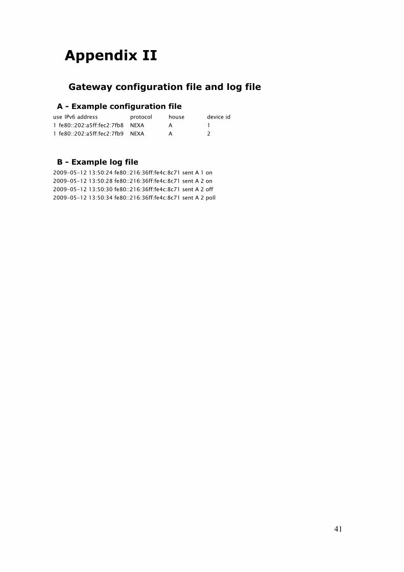
Appendix II
Gateway configuration file and log file
A - Example configuration fileuse IPv6 address protocol house device id1 fe80::202:a5ff:fec2:7fb8 NEXA A 11 fe80::202:a5ff:fec2:7fb9 NEXA A 2
B - Example log file2009-05-12 13:50:24 fe80::216:36ff:fe4c:8c71 sent A 1 on2009-05-12 13:50:28 fe80::216:36ff:fe4c:8c71 sent A 2 on2009-05-12 13:50:30 fe80::216:36ff:fe4c:8c71 sent A 2 off2009-05-12 13:50:34 fe80::216:36ff:fe4c:8c71 sent A 2 poll
41

Appendix III
Client program source code
from socket import *import sysimport array
address = sys.argv[1]port = 1981command_str = sys.argv[2]
# the socket requires all data to be in the form of byte arrayscommand_b = command_str.encode('utf-8')
#the socket is created and connects to the specified addressclientsocket = socket(AF_INET6, SOCK_STREAM)print('Connectiong to', address)clientsocket.connect((address,port,0,0)) print('Sending command',command_str)clientsocket.send(command_b) #a reply is awaited from the gatewayreply_b = clientsocket.recv(100)
#the reply is trimmed to remove characters added by the socketstr_reply=str(reply_b).lstrip('b\'').rstrip('\'')
print(address + ' says ' + str_reply)
clientsocket.close()
42

Appendix IV
Parallel port sampling software source code
#include <stdio.h>#include <stdlib.h>#include <unistd.h>#include "parapin.h"#include <unistd.h>
int main(int argc, char *argv[]){//tests if the parallel port can be initializedif (pin_init_user(LPT1) < 0)exit(0);
pin_input_mode(LP_DATA_PINS); //sets the data pins as inputs
FILE *capturefile; capturefile = fopen("capture","w+");
long sleeptime = 100; //delay time in microseconds
while(1){
if(pin_is_set(LP_PIN09)) //start writing to the file when a '1' is received{
while(1){
if(pin_is_set(LP_PIN09)){
usleep(sleeptime); printf("1\n");
fprintf(capturefile,"1\n");}else{
usleep(sleeptime);printf("0\n");fprintf(capturefile,"0\n");
}}
}}return 0;
}
43

Appendix V
Sampling program for use with WASA board
import serial #for serial port useimport time #for timing
#create a handle for the serial port with the communication settings dictated by the WASA boardser = serial.Serial(port='/dev/ttyUSB1',baudrate=1000000,parity='N',
stopbits=1,bytesize=8, xonxoff=0, rtscts=0, timeout=0)
print('Reading ' + ser.portstr) #this displays the system name of the portser.open()ser.write('ats120=0') #sets the GPIO as an inputreply = ser.readline().strip('\r\n') #reads a line with trailing CR and LF removedwhile reply != 'OK': #after a successful AT command the device is ready ser.write('at\r') ser.readline() #flush reply = ser.readline().rstrip('\r\n')print ('WASA board ready')
timer=time.time() #saves the current system timei=0ser.write('atr\r')while i<1000: #loops 1000 times reply = ser.read(1) if reply == '1' or reply == '0': print(reply) i += 1
print(i) #displays the number of samples receivedprint(time.time()-timer) #displays the time takenser.close()
44

Appendix VI
WASA board R function source code
int R_register_operation( void ){
char reg_mask;reg_mask = 1;while(1) #infinite loop{
if(P5IN & reg_mask) mts_puts("1"); # send 1 if highelse mts_puts("0"); # send 0 if low
}}
Addition to the WASA boards main switch-case statement
case 'R': cmd_ok = R_register_operation(); break;
45

Appendix VII
NEXA protocol address codes
House addressA: 0000B: X000D: 0X00D: XX00E: 00X0F: X0X0G: 0XX0H: XXX0I: 000XJ: X00XK: 0X0XL: XX0XM: 00XXN: X0XXO: 0XXXP: XXXX
Unit address1: 00002: X0003: 0X004: XX005: 00X06: X0X07: 0XX08: XXX09: 000X10: X00X11: 0X0X12: XX0X13: 00XX14: X0XX15: 0XXX16: XXXX
“Unknown” bits0XX
Command codeOFF: 0ON: X
46

www.kth.se
TRITA-ICT-EX-2009:28