ip-sharer-hub user manual - - welcome to …micronica.com.au/catalog/sharer/hip100/hip100.doc ·...
TRANSCRIPT

User Manual
UM-H-0011

Copyright
The contents of this publication may not be reproduced in any part or as a whole, stored,
transcribed in an information retrieval system, translated into any language, or transmitted
in any form or by any means, mechanical, magnetic, electronic, optical, photocopying,
manual, or otherwise, without the prior written permission.
Trademarks
All product, company, brand names are trademarks or registered trademarks of their
respective companies. They are used for identification purpose only. Specifications are
subject to be changed without prior notice.
-1-

FCC Interference Statement
This equipment has been tested and found to comply with the limits for a Class B digital
device pursuant to Part 15 of the FCC Rules. These limits are designed to provide
reasonable protection against radio interference in a commercial environment. This
equipment can generate, use and radiate radio frequency energy and, if not installed and
used in accordance with the instructions in this manual, may cause harmful interference to
radio communications. Operation of this equipment in a residential area is likely to cause
interference, in which case the user, at his own expense, will be required to take whatever
measures are necessary to correct the interference.
CE Declaration of Conformity
This equipment complies with the requirements relating to electromagnetic compatibility,
EN 55022/A1 Class B, and EN 50082-1. This meets the essential protection requirements
of the European Council Directive 89/336/EEC on the approximation of the laws of the
member states relation to electromagnetic compatibility.
-2-

Table of Contents
Chapter 1 Introduction.................................................................................51.1 Functions and Features...................................................................51.2 Packing List....................................................................................7
Chapter 2 Hardware Installation..................................................................82.1 Front Panel......................................................................................82.2 Rear Panel.....................................................................................102.3 Installation Requirements.............................................................112.4 Procedure for Hardware Installation.............................................12
Chapter 3 Software Installation.................................................................15Chapter 4 Internet Sharer...........................................................................18
4.1 Making Network Connections......................................................184.2 Configuring by Web Browser.......................................................224.3 Configuring by Console................................................................29
Chapter 5 Virtual E-mail Server................................................................315.1 Configuration for Virtual E-mail Address....................................315.2 Format of E-mail Address.............................................................345.3 Configuring E-mail Management Software..................................35
Chapter 6 Print Server...............................................................................416.1 Configuring on Windows 95/98 Platforms...................................416.2 Configuring on Windows NT Platforms.......................................446.3 Configuring on Unix based Platforms..........................................44
Chapter 7 Fax Server.................................................................................457.1 Installing the Fax Server...............................................................457.2 Phonebook Manager.....................................................................497.3 Faxing Your Documents...............................................................53
-3-

7.4 Fax Manager.................................................................................55Chapter 8 IPSMON for Windows..............................................................57
8.1 Installation and Execution............................................................578.2 Login.............................................................................................578.3 Functions for System Administrator.............................................588.4 Configuration for End Users.........................................................59
Appendix A. Glossary.................................................................................61Appendix B. Syntax of Login Script..........................................................65Appendix C. Trouble Shooting...................................................................66
-4-
Chapter 1 IntroductionCongratulations on your purchase of this outstanding all-in-1 networking device. This
product is specifically designed for Small Office and Home Office needs. It provides a
complete SOHO solution for Internet surfing and office resource sharing, and it is easy to
configure and operate for even non-technical users. Its efficiency boosting features will
increase effectiveness in any working environment. Instructions for installing and
configuring this product can be found in this manual. Before you install and use this
product, please read this manual carefully for fully exploiting the functions of this
product.
1.1 Functions and Features
This product provides several time and cost saving functions for SOHO users:
‧ Connecting multiple users to Internet by sharing one PSTN/ISDN line, one
modem/TA and one ISP account
‧ Network printing function so that purchasing another print server is not
necessary
‧ Virtual E-mail server so that the users can receive and send E-mail safely
by sharing up to eight ISP mailboxes
‧ Fax server so that the users can fax documents out through the network
‧ Web based configuration and usage condition monitoring
‧ Conforms to standard protocols for Internet connection including TCP/IP,
PPP, PAP/CHAP, DHCP/BOOTP, etc.
‧ Natural firewall to protect your intranet
‧ Automatic traffic load sharing and balancing between two WAN ports
‧ Dial-on-demand and auto-disconnection for a period of idle time
-5-

‧ Complies with IEEE 802.3 10Base-T, 10Base2 (10M model only) and
100Base-T (10/100M model only) standards
‧ Cascadable Ethernet hub function linking your Intranet to Internet
‧ Port auto-partitioning and reconnection to facilitate faulty segment
isolation
‧ Data collision and jabber handling functions
Therefore, in summary, this product has the following key features:
‧ Good expandability
This product can be simply cascaded, as required, with Ethernet hub to expand the
scale of your Intranet.
‧ High compatibility
This product is compatible with most platforms, including MS Windows 3.x/95/98,
Windows NT, UNIX and others that support TCP/IP network protocol.
‧ Dual-modem transmission capability
This product provides two serial ports for connecting to the Internet, so you can use
two modems simultaneously to get larger network bandwidth. Besides, this product
also possesses the load sharing capability.
‧ Dual-speed Ethernet interface
The 10M model provides 10 Mbps transmission speed, while 10/100M model
provides both 10 Mbps and 100 Mbps transmission speeds. 10/100M model can
automatically detect the transmission capability of physical transmission link, and
adapt itself to the same transmission speed. Data transfer between 10Base-T ports and
100Base-T ports can be automatically switched.
‧ Specifically developed for non-technical user
The friendly user interface and configuration procedure makes non-technical users
-6-

comfortable to use this product.
‧ Excellent cost saving capability
This product provides rich time and cost saving functions for Internet access sharing,
E-mail account sharing and peripheral sharing to reduce office operating cost.
Moreover, it does not require extra server or personal computer for handling these
functions so that the maintenance cost is also reduced.
1.2 Packing List
Before you try to install this product, please check all items you received against this list
to make sure nothing is missing or damaged. The complete package of this product should
contain the following items:
‧ This User Manual
‧ One IP-Sharer
‧ One installation CD-ROM (or 4 diskettes)
‧ One DC power adapter (10M model only) and one power cord
‧ Two LAN Cables
-7-

Chapter 2 Hardware InstallationThis chapter describes the panel layout and installation procedure of this product.
2.1 Front Panel
Fig. 2-1a and Fig. 2-1b illustrate the front panel of 10M model and 10/100M model
respectively. All LED indicators and RJ-45 connectors are allocated to this panel.
Figure 2-1a 10M Model Front Panel
Figure 2-1b 10/100M Model Front Panel
1. Power LED : POWER
2. COM Ports LED : COM1, COM2
3. Status LED : M1, M2
4. Collision LED : COL
5. Partition (BNC, 1-7) : Part. BNC, Part. 1-7
6. Link status and activity : Link BNC, Link 1-7
-8-

7. RJ-45 Sockets for LAN ports
8. Up Link Connection Port
9. Link Activity LED : Act 10, Act 100 (10/100M model only)
As shown in both figures, there are eight RJ-45 sockets, indicated by 1 to 7 and UPLINK,
in the front panel to connect Ethernet 10Base-T or 100Base-T (10/100M model only)
cables. The UPLINK socket is used to cascade with another hub for expanding your
Intranet. When this socket is being connected to another hub, the socket indicated by 7 can
not be used.
The functions of LED indicator lights are given in Table 2-1.
Table 2-1 Description of LED indicators in the front panel.
LEDs Function Indicator
Status
Active Description
POWER Power
indication
Yellow On Power is being applied to
this product.
COM1 Serial port 1
activity
Yellow Blinking Data transfer is in
progress through COM1.
COM2 Serial port 2
activity
Yellow Blinking Data transfer is in
progress through COM2.
M1 System status Green Blinking This product is
functioning properly.
M2 System status Green On This product is working
for some service.
Blinking This product is being
configured or upgraded.
-9-

Don’t turn it off!
COL Collision
indication
Red On Transmission collisions
have occurred on the
LAN
Part.
(10M model)
Partition
(BNC, 1-7)
Red On The corresponding LAN
port is faulty and isolated.
Please check your LAN
card.Part.
(10/100M model)
Partition
(1-7)
Link/Act.
(10M model)
Link status and
activity
Green On An active station is
connected to the
corresponding LAN port.
Blinking Data transmission is in
progress.
Link
(10/100M model)
Link status Green On An active station is
connected to the
corresponding LAN port.
Act. 10
(10/100M model)
Link activity Green Blinking At least one LAN port is
transmitting data in 10
Mbps or 100Mbps.Act. 100
(10/100M model)
2.2 Rear Panel
Fig. 2-2a and Fig. 2-2b show you the rear panel layout of 10M model and 10/100M model
respectively. Refer to these two diagrams when attempting to make connections.
-10-
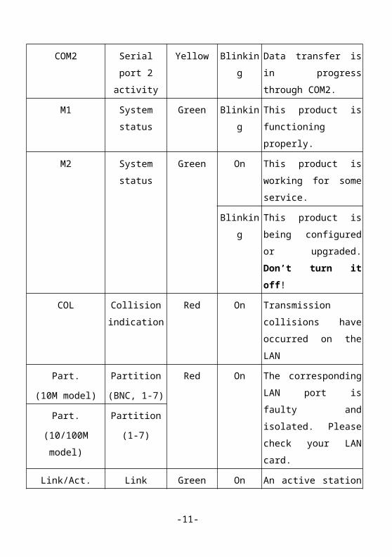
Figure 2-2a 10M model rear panel
Figure 2-2b 10/100M model rear panel
1. COM1 & COM2: Serial ports to connect MODEM or ISDN TA.
2. PRINTER: Printer port to connect printer.
3. Power Outlet: DC 5V (for 10M model only) or AC 90-230V/50-60Hz (for
10/100M model only)
4. BNC Connection Port (for 10M model only ) or Power Switch (for 10/100M
model only)
Table 2-2 shows the function and specification of each part.
Table 2-2 Description of the rear panel ports.
Ports Function Specification
POWER Power outlet DC 5V (10M model)
AC 100V~230V (10/100M model)
-11-

COM1 Serial port (WAN port) 9-pins D-type male connector
COM2 Serial port (WAN port) 9-pins D-type male connector
PRINTER Parallel port (printer port) 25-pins D-type female connector
BNC
(10M model only)
BNC coaxial cable port 10Base2 BNC connector
Power Switch
(10/100M model only)
Power on/off On/Off
2.3 Installation Requirements
This product can be positioned at any convenient place in your office or house. No special
wiring or cooling requirements is needed. However, you should comply with the
following guidelines to install:
Place this product on a flat horizontal plane.
Keep this product away from any heating devices.
Do not place this product in dusty or wet environment.
The recommended operational specifications of this product are:
Voltage/Current DC 5V / 1A for 10M model
AC 100V ~ 230V for 10/100M model
Temperature 5 ℃ ~ 55 ℃
Humidity 10 % ~ 90 %
-12-

In addition, remember to turn off the power, remove the power cord from the outlet, and
keep your hands dry when you try to install the hardware of this product.
2.4 Procedure for Hardware Installation
1. Setup LAN connections: prepare RJ-45 twist-pair cables for
connecting this product to your PCs or workstations. The 10M model also provides a
BNC port, so you can connect it to LAN via an RG-58 coaxial cable. The following
diagram illustrates the LAN connection for this product:
Figure 2-3 Setup of LAN connection for this product.
2. Connecting this product with other hubs
In case you need not to connect with another hub, skip this step.
If you want to connect with another hub, there are two approaches to build up the
connection:
(1) Connecting UPLINK port to that hub by TP straight-thru cable. In this case, the
RJ-45 port denoted by 7 can not be used.
(2) Connecting one of the RJ-45 ports denoted by 1 to 7 to that hub by TP crossover
-13-

cable. In this case, the UPLINK port can not be used.
Figure 2-4 Diagram of connecting this product with hubs.
3. Connecting this product with modems
As shown in Fig. 2-5, you can connect the serial port of your modem to the COM1 or
COM2 port of this product (if only one modem is used, the COM1 port is
recommended.) by using the RS-232 cable attached in your modem. Besides, the
phone line should be connected to the LINE port of your modem according to the
guidelines mentioned in its user manual.
-14-

Figure 2-5 Diagram of connecting this product with modem.
4. Connecting this product with your printer
Please use the printer cable to connect your printer to the printer port of this product.
5. Power on
After you finished all the connections for this product with LAN and modems, you
can connect the power cord to power on this product. This product will automatically
enter the self-test phase after it has been powered on. When it is in the self-test phase,
the indicators M1 and M2 will be lighted ON for about 5 seconds, and then M1 and
M2 will be flashed 3 times to indicate that the self-test operation has finished. Finally,
M1 will be continuously flashed once per second to indicate that this product is in
normal operation.
-15-

Chapter 3 Software InstallationAfter finishing the installation of hardware, you have to further install the attached setup
program and drivers into your platforms to make this product functioning properly in your
working environment. The software installation procedure is only for MS Windows
platforms (including Windows 95/98/NT) so you can skip this chapter if you adopt
another kind of platform.
The detailed installation procedure is described in the following:
Step 1: Insert the attached CD into your CD drive and execute the SETUP.EXE program
in that CD. Click your operation system on the Operation System frame, and IP-
Sharer-HUB on the Product frame. Then click OK button. Wait until the
following Welcome dialog to appear. Please click on the Next button.
Figure 3-1 The Welcome dialog of installation.
Step 2: When the following dialog shown, please select the destination folder to install the
programs, and click on the Next button. Then, the setup program will begin to
install the programs into the destination folder.
-16-

Figure 3-2 The Choose Destination Location dialog.
Step 3: When the installation is finished, the following window is displayed. Please click
on the Finish button.
Figure 3-3 The window to show you that the installation is finished.
Step 4: Select the item that wants to restart the computer and then click the OK button to
reboot your computer.
-17-

Figure 3-4 The screen of restarting your computer.
Step 5: After rebooting your computer, the software installation procedure is finished.
Now, you can configure the Internet Sharer (refer to Chapter 4), Virtual E-mail Server
(refer to Chapter 5) and setup the Print Server (refer to Chapter 6) and FAX Server (refer
to Chapter 7).
-18-

Chapter 4 Internet SharerThis product provides browser based configuration, that is, configuring by Netscape or
Internet Explorer. This approach can be adopted in any MS Windows, Macintosh or UNIX
based platforms.
4.1 Making Network Connections
Make sure the M1 LED flash once per second and the connections for this product have
been made according to the guidelines in Section 2.4 again. Besides, the TCP/IP
environment must have been configured properly in your computer. The default IP address
for this product is 192.168.123.254, and the default subnet mask is 255.255.255.0. These
addresses can be changed on your need, but the default values are used in this manual. If
the TCP/IP environment has not yet been configured, you should refer to the user manual
of your computer to configure.
After installing the TCP/IP communication protocol, you can use the ping command to
check if your computer has successfully connected with this product. The following
example shows the ping procedure for Windows 95 platforms. First, execute the ping
command
ping 192.168.123.254
If the following messages appear:
Pinging 192.168.123.254 with 32 bytes of data:
Reply from 192.168.123.254: bytes=32 time=2ms TTL=64
then a communication link between your computer and this product has been successfully
established, please skip to Section 4.1.2. Otherwise, if you get the following messages,
Pinging 192.168.123.254 with 32 bytes of data:
Request timed out.
-19-

there must be something wrong in your installation procedure. You have to check the
following items in sequence:
1. Is the network cable correctly connected between this product
and your computer?
2. Is the corresponding Link/Act LED in this product lighting for
your computer?
3. Is the TCP/IP environment properly configured?
Then, reboot your computer once again. If the response for ping command from this
product is still at time-out status, its IP address may have been changed for some reason.
Now, please refer to Section 4.4 to configure the IP address of this product through the
Console port.
For the Internet Sharer, there are five categories of configuration that should be
performed, including the general configuration, dial-up account configuration, modem/TA
configuration, dial-up strategy configuration and DHCP configuration.
4.1.1 General Configuration
There are four items in the general configuration:
1. IP Address: the IP address of this product whose factory setting value is
192.168.123.254.
2. Subnet Mask: the mask of IP subnet whose factory setting value is
255.255.255.0.
3. Host Name: the identifier of this product on the LAN; this item is used to
identify different devices of this product when there are more than one device of this
product installed on the LAN.
4. Functions of COM port: to enable or disable dial-up and fax-out functions.
-20-

4.1.2 Dial-up Account Configuration
Dial-up account configuration is to setup the information about the dial-up account that
you use. All of the setup items are shown as follows:
1. Static IP Address: the static IP address specified by your ISP. If your ISP assigns
you a dynamic IP address, please enter 0.0.0.0 here.
2. Phone Number: the dial-up phone number provided by ISP.
3. Account: the user’s dial-up ISP account.
4. Password: the password for the user’s dial-up account.
5. Domain Name Server (DNS) 1 and 2: the IP address of DNS hosts provided by
ISP.
6. Authentication Method: the most popular login method for the ISPs supporting
PPP/ML-PPP protocol is the PAP/CHAP; some ISPs ask for using Login Script to
login, where its syntax is described in Appendix B.
4.1.3 Modem/TA Configuration
Modem configuration is to configure your dial-up device, the analog voice-band modem
or ISDN Terminal Adapter (TA):
1. Connection Type: the item PSTN or ISDN to be selected.
2. Baud Rate: the data transfer speed between this product and modem; so its value
must be compatible with the specification of your modem. The following table
illustrates the most conservative value for configuration; you can try to raise the
configuration value from this value.
28.8K Modem 38400
33.6K Modem 57600
-21-

56K Modem 115200
ISDN TA 230400
3. H-Threshold: H-Threshold is used to determine when to start the second
connection, where its unit is bytes per second. This product will monitor the traffic of
the first connection, and start up the second modem or ISDN TA if the traffic exceeds
the H-Threshold.
4. L-Threshold: L-Threshold is used to indicate the load-sharing criterion between
two connections, where its unit is bytes per second. When the traffic of the first
connection is below the L-Threshold, no traffic will be redirected to the second
connections.
5. Volume: The volume of your modem/TA during dial-up.
6. Extra Settings: the default dial-up setting is ATE0V1. To enhance the
communication quality, you can use AT commands to configure additional settings for
your modem.
4.1.4 Dial-up Strategy Configuration
This product features the dial-on-demand function. Whenever trying to access Internet,
this product will automatically establish the dial-up connection for you. Besides, if it finds
that there is no Internet access operations for a specific time interval, it will automatically
break the dial-up connection. The setup of dial-up strategy is to define the related
parameters for the feature of dial-on-demand.
1. Maximum idle time of the main connection: The main connection is the major
channel used to access Internet. When the data transmission bandwidth of the main
connection approaches the saturation status, the secondary connection will be
automatically established to share the load of data transmission. In general, the main
connection adopts the COM1 port, while the secondary connection uses the COM2
-22-

port. However, if the main connection fails to connect Internet through the COM1
port (for examples, the modem is power off), the COM2 port is tried to replace
COM1 port as the main connection.
2. Maximum idle time of the secondary connection: This setting is the same as the
setting of maximum idle time of main connection. But, it should be smaller than that
of the main connection.
4.1.5 DHCP Setup
The settings of TCP/IP environment include Host IP, Subnet Mask, Gateway, and DNS
configurations. It is not a simple task to correctly configure all the computers in your LAN
environment. Fortunately, DHCP provides a rather simple approach to handle all these
settings. This product supports the function of DHCP server. If you enable the DHCP
function of this product and configure your computers as “automatic IP allocation” mode,
then when your PC is powered on, it can automatically load the proper TCP/IP settings
from this product. The settings of DHCP server include the following items:
1. DHCP server: If you enable the DHCP server of this product, your computer can
automatically get the information of IP address, Gateway and DNS from this product.
The default setting of the DHCP server is “enable.”
2. IP address pool for DHCP allocation: Whenever there is a computer requesting a
set of TCP/IP settings from this product, its DHCP server will automatically allocate
an unused IP address to the requesting computer from the reserved IP address range.
This setting is used to prevent those in-use IP addresses from being used in DHCP IP
allocation. For example, if there is a computer whose IP address is fixed to 100, you
should not assign the range from 96 to 111 as the reserved IP address range to the
DHCP server.
3. Fixed IP Address Mapping: There are two approaches to allocate a fixed IP
-23-

address for some client computer in your LAN:
(1) Directly assign the desired IP address to that computer without setting it in
the “automatic IP allocation” mode;
(2) Type in the desired IP address and the physical address of network interface
card of that computer in this field and set to the “automatic IP allocation” mode.
The instance of network interface card address is 00-50-18-00-0F-FE.
4.2 Configuring by Web Browser
This product builds in a Web server for users performing configuration. To make Web
based configuration, you must have a Web browser installed in your computer.
4.2.1 Start-up
Please activate your browser, disable the proxy, and set the connection address to the IP
address of this product (the factory setting URL is http://192.168.123.254). After the
connection is established, you will see the welcome page. There are four options:
1. Home Page: Bring you back to the home page (that is, the welcome page).
2. Administrator Login: Bring you to the page of Administrator Login. When you want to
configure this product, you have to choose this option to login as an administrator. The
details are described in Section 4.2.2.
3. Miscellaneous: Bring you to the page that provides some miscellaneous tools. You can
make the dial-up testing and change your user password in this page. Detailed
information is given in Section 4.2.2.
4. System Status: Bring you to inspect the system status of this product. Detailed
information is given in Section 4.2.5.
-24-

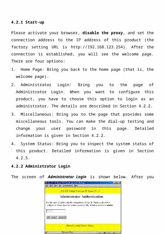
4.2.2 Administrator Login
The screen of Administrator Login is shown below. After you click on the option of
Login in the Home Page, you will step into this screen.
Figure 4-1 Screen of Administrator Login.
Please enter the password of system administration (the factory default setting is
”admin”), then click on the OK button to login as an administrator. Whenever you
successfully login as an administrator, the administrator mode page will appear.
There are five options in the menu of administrator mode; they are Home, Logout,
Configure, Misc, and Status. For the options of Home, and Status, please refer to the
descriptions in Section 4.2.1. In this section, the options of Configure and Misc are
described.
1. Configure:
-25-

Figure 4-2 Menu of Configure.
In this page, you can choose the Basic Setup mode (refer to Section 4.2.3) or Advanced
Setup mode (refer to Section 4.2.4) to configure this product.
2. Misc:
You can do many things in this page. Click on the Dial-up(1) or Dial-up(2) button will
perform a dial-up testing. Click on the Hang-up(1) or Hang-up(2) will break the
connection between this device and the ISP immediately.
Figure 4-3 Menu of Misc.
You can even change the System Password in this page. Please enter the new password
twice. If both are identical, the password can be successfully changed to the new one.
-26-

4.2.3 Basic Setup
For those non-technical users, the Basic Setup mode provides a simpler configuration
procedure.
Figure 4-4 Menu of the Basic Setup mode.
The first item in the menu of Basic Setup belong to the kind of general configuration:
1. IP Address: the IP address of this product on the LAN, whose factory default
setting is 192.168.123.254.
In the following items, Telephone, Account, Password and Domain Name Server (DNS)
belong to Dial-up Account Configuration (refer to Section 4.1.2), and Modem Type
belongs to Modem/TA Configuration (refer to Section 4.1.3). Most information for these
settings is provided by your ISP except the Modem Type.
Since there are two serial ports (COM1 and COM2) in this product, you can connect this
product with two dial-up devices (analog modem or ISDN TA), and thus the settings of
the following items are all attached with (1) or (2) to denote the setting values for
COM1or COM2 port. Note that the same value must be entered into the two fields of the
Password item for the confirmation of correct password setting. Be sure to click the Write
-27-

to Device button to store the new settings.
In addition, the Copy button at the Dial-up Account Configuration (2) denotes a one-
touch configuration scheme to directly duplicate the settings of COM1 port to COM2 port.
Of course, you can make some modifications on the copied settings for COM2.
4.2.4 Advanced Setup
For a user who wants this product to work more powerful in his LAN environment, the
Advanced Setup mode can be invoked.
In the Advanced Setup mode, you can configure all items of the five categories mentioned
in Section 4.1. Similarly, the settings of both dial-up account and modem configurations
are attached with (1) and (2) to indicate the settings for COM1 and COM2 ports
respectively.
For the descriptions of General Configuration, Dial-up Account Configuration,
Modem/TA Configuration, Dial-up Strategy, and DHCP Server, please refer to Section
4.1.1~ 4.1.5 respectively.
Figure 4-5 Menu of Advanced Setup.
-28-

Note that:
1. When your ISP only provides one domain name server, you just need to enter the
address of Domain Name Server 1, and keep the field of Domain Name Server 2
empty.
2. As shown below, DHCP setup in this product provides sixteen clusters of IP addresses
to be chosen as the IP address pool for DHCP server. Besides, you can set at most 8
fixed IP addresses for one of this product. When a client computer wants to be set to a
fixed IP address from the DHCP server of this product, a set of two fields should be
filled. The first field is denoted as the IP field to record the desired IP address, while
the second field is denoted as the Physical Address field to record the physical address
of the network interface card of that client computer.
Figure 4-6 Menu of DHCP Configuration in the Advanced Setup mode.
-29-
4.2.5 System Status
This option provides the function for observing the working status of this product:
Figure 4-7 Menu of System Status option.
1. Modem Status: Indicates the connection status of the dial-up devices connected to
this product. If any one dial-up device is connected to Internet, the IP address
obtained from ISP is displayed.
2. Connection Speed: Indicates the connection speed reported by your modem/TA.
3. Connection Time: Indicates the elapsed connection time since the dial-up
connection is established.
4. No. of Connected Hosts: Indicates the number of computers that are surfing the
Internet through COM1 or COM2 port. It is possible that one computer uses both
COM1 and COM2 ports simultaneously to access the Internet resources.
5. Printer: Indicates the status of the printer connected to this product. The possible
kinds of printer status include “Ready,” “Not plugged or no power,” “Printing xxx’s
Document”, and “Device Error.” The string xxx in the status of “Printing xxx’s
-30-

Document” shows the name or IP address of client computer asking for this printing.
The status will be automatically updated every five seconds.
4.3 Configuring by Console
Before invoking the console program, be sure to find a null modem cable and use it to
connect the COM2 port of this product with a COM port of the computer you want to
execute the console program. Then, the Console Setup procedure can start by executing a
terminal program, such as the Hyper Terminal of MS Windows 95. The connection
should be set to 19200 8-N-1. And, reboot this product. When the M1 indicator starts
flashing regularly, you can press the “Enter” key of the keyboard several times, there
should be some console messages appeared in the terminal:
Figure 4-8 Messages for Console Setup.
After entering the system password, you will get into the Console Setup mode. In this
mode, you may set the IP address and the system password of this device. You can execute
a command by entering it on the command line at the bottom of the window. The
Command List at the middle of this window lists the available commands. If you want to
save the changes you have made, please remember to execute the SR command.
-31-

Chapter 5 Virtual E-mail Server
This product provides the function of virtual E-mail server. Generally, for the sake of
personal privacy, one E-mail account is owned and used by only one user. The virtual E-
mail server denotes an E-mail system that provides the feature of E-mail account sharing
but retains privacy for every one. In other words, all members of a company, a division or
a family can share one ISP mailbox but each one can access his E-mails safely. This
product features the virtual E-mail server that up to 64 users can be grouped as you wish
to share up to 8 real ISP mailboxes. Therefore, it has the following benefits:
1. being able to manage the E-mails systematically based on the divisions of a
company,
2. being able to avoid mailbox overloading.
5.1 Configuration for Virtual E-mail Address
To setup the virtual E-mail server, please follow the steps shown below:
1. Make the web based configuration (please refer to Section 4.2.1).
2. Login as an administrator (please refer to Section 4.2.2).
3. click on "here" in the window shown in Fig 4-2. The virtual e-mail server account
management screen will be shown.
-32-

Figure 5-1 The Virtual E-mail Server configuration
4. In the Virtual E-mail Server Management menu, choose "Mailboxes" to the Mailboxes
Management menu. You can add, delete or edit e-mail accounts here. Each account can
be shared by at most eight persons.
Figure 5-2 Mailboxes Management
-33-
5. Choose "add", type the e-mail address in the first column and the password for the
address in the second. Retype the password in the second column to assure the
correctness. You'll have to repeat the same process if you choose "edit property" to edit
an account.
Figure 5-3 Edit a mailbox data entry
6. Choose "Users" in the Virtual E-mail Sever Management menu, you can edit the users
who want to share the account.
-34-

Figure 5-4 User Management for the Virtual E-mail Server
7. Choose "add" will add a new user into the list, fill in the user's name , user's password
in the first two columns. Retype the password in the third column. Click the list box to
choose which e-mail account this user will use.
Figure 5-5 Edit a user data entry
8. Choose "Write to device" when you've finish it.
5.2 Format of E-mail Address
For a user who uses the virtual E-mail server function, his E-mail address should comply
with the format defined as follows
"user identifier"<the mailbox address he uses>
or
user identifier<the mailbox address he uses>
For example, suppose there is a user whose identifier (name) is Rupert, and the mailbox
-35-

that he uses is [email protected]. Then, the complete E-mail address of
Rupert can be either one of the following two formats:
"Rupert"<Mailbox1 @ XCompany .com.tw >
or
Rupert<Mailbox1 @ XCompany .com.tw >
5.3 Configuring E-mail Management Software
In this section, we briefly present the configuration procedure for some popular E-mail
management tools to efficiently utilize the function of virtual E-mail server. The
demonstrated tools are Netscape 4.0 Messenger and Outlook Express.
1. Netscape 4.0 Messenger:
(1) Open the Netscape 4.0 Messenger:
Figure 5-6 Main screen of Netscape 4.0 Messenger.
(2) Select the Preferences command from the menu of Edit option:
-36-

Figure 5-7 Screen of Preferences command.
(3) Select the item Identity in Mail & Groups from the Category list:
Figure 5-8 Screen of Preferences command when the item Identity is chosen.
(4) Type in the user name and his mailbox address.
(5) Select the item Mail Server in Mail & Groups from the Category list:
-37-

Figure 5-9 Screen of Preferences command when the item Mail Server is chosen.
(1) Enter the user name in the Mail server user name field.
(2) Enter the address of the outgoing mail server in the Outgoing mail (SMTP) server
field. In general, it is the address of the mail server provided by your ISP, contact
your ISP if you don’t know any.
(3) Enter the IP address of this product in the Incoming mail server field so that this
product is adopted as the virtual E-mail server.
(4) Configure the Mail Server Type to POP3.
Finally, when you want to receive E-mails, you must type in your password to get E-
mails from the specified mailbox.
2. Outlook Express
(1) Open the Outlook Express:
-38-
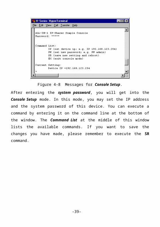
Figure 5-10 Main screen of Outlook Express.
(2) Select the Accounts command from the menu of Tools option:
Figure 5-11 Screen of Accounts command in the Tools option.
-39-

(3) Select your account in the Mail option and then click the Properties button:
Figure 5-12 Screen of Properties of user account.
(4) Choose the General option and then type in the user name in the field of Name.
(5) Type in the user’s mailbox address in the field of E-mail address.
(6) Select the Servers option in Fig. 5-13:
-40-
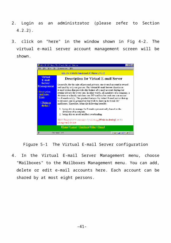
Figure 5-13 Screen of Servers option in Outlook Express
(7) Enter the address of the outgoing mail server in the Outgoing mail -SMTP field.
In general, it is the address of the mail server provided by your ISP, contact your
ISP if you don’t know any.
(8) Enter the IP address of this product in the Incoming mail-POP3 field so that this
product is adopted as the virtual E-mail server.
(9) Enter the user name in the field of Account name and the user’s password in the
Password field.
-41-

Chapter 6 Print Server
This product provides the function of network print server for MS Windows 95/98/NT and
Unix based platforms. In this chapter, the installation and setup procedures are presented.
6.1 Configuring on Windows 95/98 Platforms
After you finished the software installation procedure as described in Chapter 3, your
computer has possessed the network printing facility provided by this product. For
convenience, we call the printer connected to the printer port of this product as server
printer. On a Windows 95/98 platform, open the Printers window in the My Computer
menu:
Figure 6-1 Screen of My Computer/Printers window.
Now, yon can configure the print server of this product according to the following
procedure:
-42-

1. Find out the corresponding icon of your server printer, for example,
the HP LaserJet 6L. Click the mouse’s right button on that icon, and then select the
Properties item:
Figure 6-2 Menu of Properties item for server printer on Windows 95/98.
2. Click the Details item:
Figure 6-3 Dialog box of Details item.
3. Choose the “PRTmate: (All-in-1)” from the list attached at the Print To item. Besides,
be sure that the Printer Driver item is configured to the correct driver of your server
-43-

printer.
4. Then, click on the button of Port Settings:
Figure 6-4 Dialog box of Printer Position.
Type in the IP address of this product and then click the OK button.
5. Make sure that all settings mentioned above are correct, then click the OK button.
Now the configuration procedure of the print server of this product is finished.
-44-

6.2 Configuring on Windows NT Platforms
The configuration procedure for a Windows NT platform is similar to that of Windows
95/98 except the slightly different layout and terminologies in the screen of printer
Properties:
Figure 6-5 Dialog box of Ports item on Windows NT.
Compared to the procedure in last section, the selection of Details is equivalent to the
selection of Ports, and Port Settings is equivalent to Configure Port.
6.3 Configuring on Unix based Platforms
Please follow the traditional configuration procedure on Unix platforms to setup the print
server of this product. The printer name is “lp.”
-45-

Chapter 7 Fax Server
The fax server of this product can be executed on MS Windows 95/98/NT platforms.
Note, to make the Fax Server operate properly, you need to use a Class 1 fax modem.
7.1 Installing the Fax Server
In this section, we describe the installation procedure of the fax server for different
platforms.
7.1.1 Installation for Windows 95/98 Platforms
Step 1. At the menu of Printers of My Computer icon, choose the item of Add Printer:
Figure 7-1 Screen of Add Printer Wizard.
Click the Next button.
-46-

Step 2. Choose the Local Printer option and then click the Next button:
Figure 7-2 Menu of selecting printer position in Add Printer Wizard.
Step 3. Choose All-in-1 in the Manufacturers item and FAX_Driver in the Printers item,
then click the Next button:
Figure 7-3 Menu of selecting printer model in Add Printer Wizard.
Step 4. Choose FAXmate: All-in-1 and then click the Next button:
-47-

Figure 7-4 Menu of selecting printer port in Add Printer Wizard.
Step 5. Type in the printer name: IP_Sharer_FAX_Driver and then click the Next button:
Figure 7-5 Menu of typing in printer name in Add Printer Wizard.
-48-

Step 6. You have finished the installation procedure of the fax server of this product.
Then, you can invoke it to transfer your documents by selecting the printer:
IP_Sharer_FAX_Driver.
7.1.2 Installation for Windows NT Platforms
Step 1. At the menu of Printers of My Computer icon, choose the item of Add Printers
Step 2. Choose the My Computer item and then click the Next button:
Figure 7-6 Menu of selecting printer position in Add Printer Wizard.
-49-

Step 3. Choose FAXmate and then click the Next button:
Figure 7-7 Menu of selecting printer port in Add Printer Wizard.
Step 4. Please refer to Step 3. in Section 7.1.1.
Step 5. Please refer to Step 5. in Section 7.1.1.
Step 6. Please refer to Step 6. in Section 7.1.1.
7.2 Phonebook Manager
The Phonebook Manager is developed to support users a friendly manner to fax his
documents. To activate Phonebook Manager, you should select the item of Phonebook
Manager in the workgroup of Start / Programs / IP-Sharer-HUB of your Windows
screen:
-50-

Figure 7-8 Main menu of Phonebook Manager.
At this menu, you can handle two kinds of receiver information: Entities and Groups. The
former record information about the target persons or companies you may transfer
documents, while the latter record information about the groups of target persons or
companies you may transfer documents simultaneously:
Figure 7-9 Main menu of Phonebook Manager for group facsimile.
7.2.1 Editing Personal Information
Click the button of Personal Information for editing the information of fax server
manager:
-51-

Figure 7-10 Menu of Editing Personal Information.
At this menu, you can also attach into your picture by clicking on the Load button:
Figure 7-11 Menu of Open Files for loading BMP file.
Please choose your BMP file to load. Finally, click the OK button to store the personal
information.
7.2.2 Editing Information of Entities
At the menu of Fig. 7-8, click the Add button (or double click the left button of your
-52-

mouse or press the Enter key in your keyboard on an empty entity) to edit the information
of a new entity. The menu of Editing Entity Information is the same as Fig. 7-10.The
inserted new entity will be shown in the main menu of Phonebook Manager.
When you want to modify an existing entity, please click the Edit button at the main menu
(or double click the left button of your mouse or press the Enter key in your keyboard) on
that entity to modify its data. The menu and procedure of this job is the same as inserting a
new entity mentioned above.
When you want to delete an existing entity, click the Delete button at the main menu (or
press the Delete key in your keyboard) on that entity. Then, a menu will be shown to ask
for confirmation. After you click the Yes button, that entity will be removed from your
main menu.
7.2.3 Editing Information of Groups
The function of Groups is to support the facsimile of a document to multiple target
receivers simultaneously.
At the menu of Fig. 7-9, click the Add button (or double click the left button of your
mouse or press the Enter key in your keyboard on an empty entity) to edit a new group of
entities:
-53-

Figure 7-12 Menu of Editing Group Information.
At this menu, you should type in the group name and comments first. Then, you further
step in the procedure that edits the lists of Member Entities form the list of Non-member
Entities. Four buttons can be used:
1. “<”: Move the selected entities from the Non-member Entities list to the Member
Entities list.
2. “<<”: Move all non-member entities to the Member Entities list.
3. “>”: Remove the selected entities from the Member Entities list.
4. “>>”: Remove all member entities in the Member Entities list.
Click the OK button to store the edited new group into the phonebook. The usage of Edit
and Delete buttons is the same as that of Entities menu.
7.3 Faxing Your Documents
The procedure of using the fax server to transfer a document is similar to that of printing a
document. For example, when you have edited a document in Microsoft Word and want to
fax it, you can choose the Printing command in the menu of Files in Microsoft Word
screen:
-54-

Figure 7-13 Menu of Printing command in Microsoft Word.
Choose IP_Sharer_FAX_Driver as printer name and then click the OK button:
Figure 7-14 Menu of Fax Schedule Editor.
At this menu, you can edit the following items:
1. Fax Job Name: the name denoted to represent this fax job. In case you do not edit this
information, the fax server will automatically create a job name for you according to
the receiver information.
-55-

2. Fax Date and Fax Time: the time when this fax job is executed. If the fax job is
expected to be executed immediately, these two information need not be edited.
3. Retry Times and Retry Minutes: When the fax job fails due to some reason, the fax
server will automatically retry again and again until the settings of these two items are
reached. If the fax job still can not be completed, it will be aborted to wait for user’s
instruction.
4. Receiver List: the list of receivers of this fax job.
5. Non-receiver List: the list of entities and groups that are not the selected receivers but
are in the phonebook.
Besides, there are five buttons:
1. “<”: Move the selected entities or groups from the Non-receiver list to the Receiver
list.
2. “<<”: Move all Non-receiver entities and groups to the Receiver list.
3. “>”: Remove the selected entities or groups from the Receiver list to the Non-
receiver list.
4. “>>”: Remove all entities and groups in the Receiver list to the Non-receiver list.
5. Add: When the data of receiver has not yet been edited into the phonebook, you can
click this button to edit it. The menu and procedure of this job is the same as those
mentioned in Section 7.2.2.
Remember to click the OK button for executing the desired fax job.
7.4 Fax Manager
Fax Manger is responsible for executing the scheduled fax jobs and monitoring the
execution status. Its icon is listed in the working list on the bottom of Windows screen.
Open this icon, you will get the following menu:
-56-

Figure 7-15 Menu of Fax Manager.
At this menu, you can choose one job and then click the right button of your mouse on
that job to watch its detailed information or change the job status. The pop-up menu
includes the following items:
1. Cancel: Cancel the selected fax job.
2. Suspend: Suspend the selected fax job.
3. Suspend All: Suspend all of the fax jobs.
4. Reset: The selected job is resetted to wait for being executed.
5. Contents: It is used to show the detailed information of the selected fax job at the
following menu:
-57-

Figure 7-16 Menu of Contents of a fax job.
Note that all fax jobs will be suspended after you close the Fax Manager.
-58-

Chapter 8 IPSMON for WindowsIPSMON for Windows is a monitor program of this product. This program can be
executed on the Microsoft Window 95/98/NT platforms. The following conditions present
the opportunities when you have to execute it:
1. when you want to watch the connection status or log information of this product,
2. when you want to change your password (end user).
8.1 Installation and Execution
Please install IPSMON for Windows on your MS Windows platforms according to the
procedure described in Chapter 3. Besides, be sure that this product has been installed
correctly by complying with the procedure mentioned in Section 2.4. Then, you can
invoke this program by selecting the Start / Programs / IP-Sharer-HUB / IPSMON
for Windows command from the working list on your Windows.
8.2 Login
When the IPSMON for Windows is started, it will try to check whether this product has
been installed in your LAN environment. If it fails to find the device, an error message
will be shown. Otherwise, the following dialog box will be displayed:
-59-

Figure 8-1 Dialog box for login
At the dialog box, please key in the password of the administrator or choose the item of
End User for performing the configuration for an end user, then click the Login button to
step in the process. The factory setting password is admin. The installed device
information is shown in the first line of this dialog box, including the device type and IP
address. When you finish the configuration process, IPSMON will bring you back to this
dialog box again. At that time, you have to click on the Exit button to complete the job.
Besides, you can click on the About button to see the information about this product.
8.3 Functions for System Administrator
When you login as a system administrator, the following menu will be displayed to you:
Figure 8-2 Main menu of System Administrator.
At the menu, you can choose one of the following options to configure this product:
1. Miscellaneous:
The Miscellaneous page is shown in Fig 8-2. There are several miscellaneous functions in
this menu including
-60-

(1) Disconnect to ISP: Clicking on this button will request this product to break the dial-
up connection. If there is no user in accessing the Internet, the dial-up connection will
be broken immediately. Otherwise, the request will be ignored. Suggest you click this
button in case you will not surf the Internet for a long time
(2) Monitor Connection Status: The displayed sending rate and receiving rate are the sum
of COM1 and COM2 ports, and those data shown in this menu is refreshed every
second.
(3) Reboot IP Sharing Device: Clicking on this button will force this product into the
reset state. Before it starts the reset operation, the system will check whether there is
any user accessing the network. If it does, a message will be displayed to inform you
that there is still someone accessing the network. If you reconfirm to reset this
product anyway, the reset operation will be started.
2. Password:
For the concept of changing password, please refer to Section 4.2.2. Note that the
length of the password must not exceed 9 characters.
3. Log:
The information of system log is also recorded as a file named IPSMON.LOG.
8.4 Configuration for End Users
When you login as an end user, the following menu will be displayed to you:
-61-

Figure 8-3 Main menu of End User.
At the menu of End User, There are only two functions that can be configured:
1. Disconnect to ISP in Miscellaneous page: Please refer to Section 8.3.
2. Change User Password in Password page: Please enter the user name, the old
password and the new password into the corresponding fields. Besides, enter the same
new password into the Reconfirm field to make sure that the new password is correctly
typed in. Finally, click on the OK button. The limitations of changing password include
(1) the length of a user name can not exceed 15 characters and (2) the length of a
password can not exceed 15 characters.
-62-

Appendix A. Glossary
Authentication: the procedure to verify user identity as a security measure. Passwords
and digital signatures are the most popular forms.
BOOTP: Bootstrap Protocol, a method to determine the IP address of a diskless system
when it is bootstrapped. The official specification for BOOTP was given in RFC 951.
Domain Name: a unique identifier that represents each computer on the Internet. Some
computers may have more than one domain name. “www.XCompany.com.tw” is an
example of a domain name, where the “com.tw” indicates a commercial organization in
Taiwan.
DHCP: Dynamic Host Configuration Protocol. A protocol that provides a means to
dynamically allocate IP addresses to computers on a local area network. The official
specification for DHCP was given in RFC 2131.
Dial-up: the procedure that activates a computer’s modem to connect it to the ISP.
E-mail: an electronic manner of sending messages to other people from your computer. It
is a widely used facility on the Internet.
Fax Server: an application program that controls one fax machine for being shared by the
computers over a LAN. It is a facility of a server computer linking to the LAN, or an
-63-

embedded device attached to the LAN.
FTP: File Transfer Protocol. It allows a user on one computer to transfer files to and from
another computer over a TCP/IP network. A computer on the Internet which specifically
stores digital files for users to FTP to their own computers is called a FTP site.
HTML: Hyper Text Markup Language – a text based language used to build WWW
pages and interpreted by Web browsers.
HTTP: HyperText Transmission Protocol which is a protocol that computers on the
Internet use to communicate with each other.
Hypertext: text that contains links which can be clicked with a mouse. When the user
clicks the link, he is taken to another document or a different section of the current
document.
Internet: a world wide computer network through which you can send mails, retrieve
digital information, or chat to people electronically.
Intranet: an internal Internet for enterprises with several branch offices over different
places. It can be used by anyone who is directly connected to the enterprise computer
network.
IP Address: Internet Protocol address. It is a unique number used to represent every
-64-

computer in a network. The format of the IP address is 4 fields separated by dots, for
example, 192.168.132.250
ISDN: Integrated Service Digital Network. It is a fast digital phone line provided by most
phone companies. To be able to reap the benefits you will need to add a special card to
your computer and your Internet Service Provider must be able to provide an ISDN
connection.
ISP: Internet Service Provider which is a company that provides access to the Internet for
people. The company handles the link from your computer to the rest of the Internet.
POP: Post Office Protocol, a standard protocol for exchanging E-mails between a user’s
computer and the ISP.
PPP: Point to Point Protocol, a standard protocol for using a modem and telephone line to
connect to the Internet by over TCP/IP.
Print Server: an application program that controls one or more printers for being shared
by the computers over a LAN. It is a facility of a server computer linking to the LAN, or
an embedded device attached to the LAN.
SLIP: Serial Line Internet Protocol, a protocol allowing the Internet Protocol to be used
over a serial line, e.g. an RS-232 serial port connected to a modem. The official definition
was given in RFC 1055.
-65-

SMTP: Simple Mail Transfer Protocol, a server-to-server protocol for delivering
electronic mail. It is used on the Internet and also used on other TCP/IP networks.
TCP/IP: Transmission Control Protocol/Internet Protocol, a standard set of protocols that
govern the basic workings of the Internet. The TCP part is all about ensuring that data is
transmitted correctly between two computers. The data transmitted is split up into small
portions called data packets. The IP part of TCP/IP is how these data packets are moved
from one point to another. Each computer on the Internet has a unique IP address and the
data packets are moved from the source to the destination through many different
computers and this is controlled via TCP/IP.
Telnet: a program which is a part of the TCP/IP protocol. Its purpose is to allow a user to
login to a computer from a remote location.
URL: Uniform Resource Locator, which defines how documents on the WWW are
referenced. The URL contains the protocol to be used, e.g. HTTP.
WAN: Wide Area Network, a linked network of LANs basically. The Internet can be
considered to be considered to be the largest WAN there has ever been.
Web Browser: An application program used to surf(serve) the WWW cyberspace. It
interprets HTML and presents final Web page. Examples include Netscape Navigator, MS
Internet Explorer, etc.
-66-

WWW: World Wide Web, an Internet facility that allows you to browse linked web pages.
-67-

Appendix B. Syntax of Login Script #: comments; the strings behind this character will be treated as comments.
idle NNNN: idle time; the idle time will be NNNN ms.
send "AAAA": send string; the string AAAA 以及 carriage return code (that is, the
code Enter key) are sent. The send can be followed by $USER or $PASS to denote
the account and password in a dial-up configuration respectively, for examples, send
“ppp” and send $USER.
wait "AAAA": wait for string AAAA, for example, wait “=>”.
Example:
### SAMPLE LOGIN SCRIPT ###
idle 2000 #idle 2 seconds
send "" #press [Enter]
wait "sername"
send $USER
wait "assword"
send $PASS
idle 1000
send ""
wait "===>"
send "1" #select PPP
-68-

Appendix C. Trouble ShootingTable C-1 Basic Diagnosis
Check Items Corrective Action
Has the power already turned on?
1. Is the power LED light?
2. Is the power switch turned on?
(10/100M model only)
3. Is the power cable connected?
1. Connect the power cable.
2. Turn the power switch on (10/100M model
only).
Does this product operate normally?
1. Does the M1 LED flash once per
second?
Re-power on this product and wait for about 10
seconds.
Does your computer connect to this
product correctly?
1. Is the corresponding Link/Act.
LED (10M model) or Link LED
(10/100M model) for your computer
light?
1. Inspect the network cable and its connection
between this product and your computer.
2. Check the network interface card of your
computer.
Does the data communication
between your computer and this
product normally?
1. Execute the ping command to the
IP address of this product on your
computer. Does your computer get the
reply from this product?
When this product does not respond to the ping
command:
1. The IP address of this product may have been
changed, so please use the correct IP address to
configure this product again.
2. Reboot this product after reconfiguring.
-69-
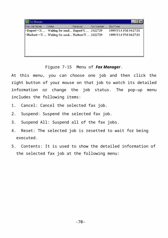
Table C-2 Trouble Shooting for Web-based Configuration
Check Items Corrective Action
Has assigned a proxy? Disable the proxy or add the IP address of this
product into the Exceptions of the proxy.
Was an incorrect address entered into
the URL of your browser?
Enter the correct URL of this product (If you have
forgot its address, execute the IPSMON for
Windows software).
-70-

Table C-3 Trouble Shooting for Internet Sharer
Check Items Corrective Action
Is TCP/IP configuration correct? Configure the TCP/IP environment carefully.
Were the dial-up device and dial-up
account configured correctly?
Adopt Web mode (refer to Chapter 4) or IPSMON
(refer to Chapter 8) to check the configuration of
dial-up device and dial-up account, and correct
error settings.
Was the dial-up device normally
connected to this product?
1. Make sure that the dial-up device is powered on.
2. Make sure that the connection between dial-up
device and this product is OK.
3. Make sure that the connection between dial-up
device and telephone line is OK.
4. Observe the system status by Web mode (refer to
Section 4.2.5) to check the connection status of
the dial-up device.
Table C-4 Trouble Shooting for Print Server
Check Items Corrective Action
Is the connection between printer and
this product correct?
Make sure that the printer is correctly connected to
the printer port of this product.
Is the printer ready? Make sure that the printer is at the Ready status by
entering the System Status mode in the Web page
of this product. If the printer is not ready, re-start
up this product and the printer.
-71-

Was the printer type correctly
selected?
Select a correct printer type in your computer, and
then print the document again.
Was the printer driver installed
correctly?
1. Make sure that the printer driver has been
installed (refer to Chapter 6).
2. When the message “there was an error writing
to…” appears, check the settings of the printer
port and correct the error settings (refer to
Chapter 6).
Was the correct printer driver
installed?
In case the printing result is abnormal, connect the
printer to your computer directly, then print the
document again. If the abnormal phenomenon still
exists, that indicates installing an error printer
driver. Please install the correct driver or contact
with the supplier of your printer.
Table C-5 Trouble Shooting for Fax Server
Check Items Corrective Action
Was the fax modem normally
connected to this product?
1. Make sure that the fax modem is powered on.
2. Make sure that the connection between fax
modem and this product is OK.
3. Make sure that the connection between fax
modem and telephone line is OK.
4. Observe the system status by Web mode (refer to
Section 4.2.5) or IPSMON (refer to Section 8.3) to
-72-

check the connection status of the fax modem.
Was the printer type for fax correctly
selected?
Select IP_Sharer_Fax_Driver as the printer type
in your computer, and then fax the document again.
Was the fax driver installed correctly? Make sure that the fax driver provided by this
product has been installed (refer to Chapter 7).
Table C-6 Virtual E-mail Server
Check Items Corrective Action
Is the product able to connect to ISP? If it can’t, please follow Table C-3 procedure to
diagnose.
Was the E-mail management tool
configured correctly?
Check the configuration of adopted E-mail
management tool by referring to Section 8.4.5.
Was the mailboxes and mail users
configured correctly?
Check the configuration of mailboxes and mail
users by referring to Section 8.4.5.
-73-