ip office technical bulletin - avaya · laborious task of using paper labels to denote phone...
TRANSCRIPT

COMPAS ID 136101 Issue 2 Page 1 of 88
IP Office Technical Bulletin Bulletin no: 36 Date: 21st March 2005 Title: General Availability (GA) of IP Office 3.0
Software

IP Office Technical Bulletin number 36
COMPAS ID 136101 Issue 2 Page 2 of 88
Table of Contents
1 Product Overview............................................................................................................4 2 IP Office Hardware.........................................................................................................6
2.1 New Digital Phones - 5400 Series .................................................................6 2.2 New IP Phones - 5600 Series........................................................................9 2.3 Support for 2402 and 2410 Digital Phones..................................................13 2.4 Support for 4601 and 4610 IP Sets .............................................................14 2.5 EU24 Expansion Module .............................................................................15 2.6 201A Recorder Interface Module.................................................................15 2.7 Modem 12 Card ...........................................................................................15
3 IP Office Software Enhancements .....................................................................16 3.1 Key System Features ..................................................................................16
3.1.1 Call Appearance ........................................................................................16 3.1.2 Bridged Appearance ..................................................................................18 3.1.3 Line Appearance........................................................................................19 3.1.4 Call Coverage ............................................................................................21 3.1.5 Idle Line Preference...................................................................................23 3.1.6 Ringing Line Preference ............................................................................24 3.1.7 Hold Functionality ......................................................................................25 3.1.8 LED Feedback ...........................................................................................25
3.2 Distinctive Ringing .......................................................................................26 3.3 SNMP Alarms for Applications.....................................................................26 3.4 Embedded Voicemail for IP406v2 ...............................................................26 3.5 Enhancements to Small Office Edition Embedded Voicemail .....................26 3.6 Changes in Manager ...................................................................................26
4 IP Office VoiceMail Pro .............................................................................................26 4.1 Personal Distribution Lists ...........................................................................26 4.2 Group Message Broadcast ..........................................................................26 4.3 ContactStore for IP Office............................................................................26 4.4 Fax Server Support......................................................................................26 4.5 SNMP Alarms ..............................................................................................26
5 IP Office Conferencing Center .............................................................................26 5.1 Local Address Book.....................................................................................26 5.2 Conference Templates ................................................................................26 5.3 Installation Enhancements...........................................................................26
6 IP Office User Applications....................................................................................26 6.1 PhoneManager ............................................................................................26
6.1.1 Profiles..................................................................................................26 6.1.2 Compact Mode (Pro Only)....................................................................26 6.1.3 Speed Dial Enhancements ...................................................................26 6.1.4 Personal Distribution List Support (Pro Only).......................................26 6.1.5 Microsoft LIVE Communication Server Support ...................................26 6.1.6 Drag and Drop Functionality.................................................................26 6.1.7 Import/Export of Local Directories (Pro Only) .......................................26 6.1.8 Call History Enhancements (Pro Only).................................................26 6.1.9 Programmable Date and Time Format (Pro Only)................................26 6.1.10 PhoneManager PC Softphone USB Settings .......................................26
6.2 SoftConsole .................................................................................................26

IP Office Technical Bulletin number 36
COMPAS ID 136101 Issue 2 Page 3 of 88
7 Wizards ..................................................................................................................................26 7.1 Password Protection....................................................................................26 7.2 Moves Adds and Changes Wizard Enhancements .....................................26 7.3 Wizard Support for Embedded Voicemail and VoiceMail Pro......................26
7.3.1 Embedded Voicemail Support ..............................................................26 7.3.2 VoiceMail Pro Support..........................................................................26
7.4 Reports For Voicemail Pro Automated Attendants ......................................26 8 CCC Compatibility........................................................................................................26 9 Windows Operating System Support for IP Office 3.0.....................26 10 Issues Resolved in IP Office 3.0 Software ...............................................26
10.1 Core Software ..........................................................................................26 10.2 VoiceMail Pro ...........................................................................................26 10.3 IP Office Conferencing Center .................................................................26 10.4 User Applications .....................................................................................26
10.4.1 PhoneManager .....................................................................................26 10.4.2 SoftConsole ..........................................................................................26 10.4.3 TAPI......................................................................................................26
10.5 Wizards ....................................................................................................26 10.6 DECT .......................................................................................................26
11 Known Issues ................................................................................................................26 11.1 Core Software ..........................................................................................26 11.2 Manager ...................................................................................................26 11.3 VoiceMail Pro ...........................................................................................26 11.4 IP Office Conferencing Center .................................................................26 11.5 User Applications .....................................................................................26
11.5.1 PhoneManager .....................................................................................26 11.5.2 SoftConsole ..........................................................................................26 11.5.3 TAPI......................................................................................................26
11.6 Wizards ....................................................................................................26 11.7 DECT .......................................................................................................26
12 Technical Notes ...........................................................................................................26 12.1 Upgrade Installation Notes.......................................................................26 12.2 IP406, IP406v2, IP412, and Small Office Edition Upgrade Instructions...26 12.3 IP403 Upgrade Instructions......................................................................26 12.4 Unit Compatibility - Expansion Unit Interoperability .................................26 12.5 DS Phone Firmware Upgrades ................................................................26 12.6 Phone Firmware Support .........................................................................26 12.7 Upgrade Instructions for VoiceMail Pro....................................................26 12.8 Upgrade Instructions Small Office Edition Embedded Voicemail.............26 12.9 Upgrade Instructions for IP Office Conferencing Center..........................26 12.10 Upgrade Instructions for IP Office User Applications ...............................26
13 Assistance.........................................................................................................................26 13.1 Documentation & Software ......................................................................26 13.2 IP Office Technical Training .....................................................................26

IP Office Technical Bulletin number 36
COMPAS ID 136101 Issue 2 Page 4 of 88
IP Office Technical Bulletin Bulletin No: 36 Date: 21st March 2005 Region: GLOBAL
General Availability (GA) of IP Office 3.0 Software Avaya is delighted to announce the launch and availability of IP Office 3.0 software. IP Office is Avaya’s Small and Medium Enterprise (SME) solution designed as a global solution for customers with up to 360 extensions and 120 trunks. 1 Product Overview
The Avaya IP Office 3.0 software is the latest advancement in converged voice and data technology from Avaya. IP Office combines high-end voice and data applications, allowing the smallest of businesses to deliver cutting edge customer service. IP Office 3.0 is the entry-level software to support the following new hardware:
• New Digital Phones – 5400 series • New IP Phones – 5600 series • 2402 and 2410 Digital Phones • 4601 and 4610 IP Phones • EU24 Expansion Module • 201A Recorder Interface Module • Modem12 Card
As well as increased reliability through improvements to the core system software, IP Office 3.0 also supports the following new features: IP Office Core Software (Version 3.0.40)
• Key System Features • Distinctive Ringing • Enhanced SNMP Alarms • Embedded Voicemail on the IP 406v2 Platform • Small Office Edition Voicemail Enhancements
IP Office Technical Bulletin number 36
COMPAS ID 136101 Issue 2 Page 5 of 88
IMPORTANT INFORMATION
The Avaya 20xx (DT) handsets are not supported in IP Office 3.0. A further IP Office build will be released in the near future, IP Office 3.0DT, which will support 20xx handsets. However this will not support the features or applications described in this document. Please refer to the separate communication that was sent out regarding this. Note: The IP403DT can run 3.0 software but there is no support for the connection of DT handsets to the 8 onboard ports. Please also note that IP Office 3.0 software is not supported on the IP401 platform.
IP Office VoiceMail Pro (Version 3.0.13)
• Personal Distribution Lists • Group Message Broadcast • ContactStore For IP Office • Fax Server Support
IP Office Conferencing Center (Version 3.0.10) • Local Address Book • Conference Templates • Installation Enhancements
PhoneManager (Version 3.0.12) • Profiles • Compact Mode • Speed Dial Enhancements • Personal Distribution List Support • Microsoft LIVE Server Support • Drag-n-Drop Functionality • Import/Export of Local Directories • Call History Enhancements • Programmable Date and Time Format • PhoneManager PC Softphone USB Settings
SoftConsole (Version 3.0.8) • Call Information Panel Enhancements
Installation Wizards (Version 3.0.21) • Password Protection • Moves, Adds and Changes Wizard Enhancements • Wizard Support for Embedded Voicemail and VoiceMail Pro
IP Office 3.0 Engineers Toolkit (Version 3.0)

IP Office Technical Bulletin number 36
COMPAS ID 136101 Issue 2 Page 6 of 88
2 IP Office Hardware
The following new hardware is supported with IP Office 3.0 software: 2.1 New Digital Phones - 5400 Series Coincident with the launch of IP Office 3.0 is a new range of Digital phones, the 5400 series, which are SMBS’s own range of terminals for the IP Office. These phones are based on the existing 2400 series Digital phones but have been developed specifically for IP Office and will operate ONLY on the IP Office and IP Office Small Office Edition. These phones connect to the IP Office via DS phone ports. There are 3 different phones in the range, the 5402, the 5410 and the 5420. The 5410 and 5420 have the ability to download new firmware to the phones. This allows you to take advantage of key product upgrades and feature enhancements. 5402 – Basic Digital Phone The Avaya 5402 is a cost effective two-wire digital telephone designed to complement the 5410 mid-level and 5420 executive telephones.
• 2-line x 24-character display with 2 programmable Call Appearance/feature buttons. To ensure correct call handling these should be programmed as Call Appearance buttons.
o 12 programmable feature buttons can be accessed via the FEATURE button (not suitable for call appearance features).
• Listen-only speaker. • 10 Fixed Feature Buttons: Conference, Transfer, Drop, Redial, Speaker,
Message, Hold, Mute, Volume Up & Down, and Feature (to access 12 additional dial pad features).
• Hearing Aid Compatible. • Large Message Waiting Indicator. • Eight Personalized Ring Patterns. • Adjustable Desk Stand. • Either desk or wall mountable.
IP Office Technical Bulletin number 36
COMPAS ID 136101 Issue 2 Page 7 of 88
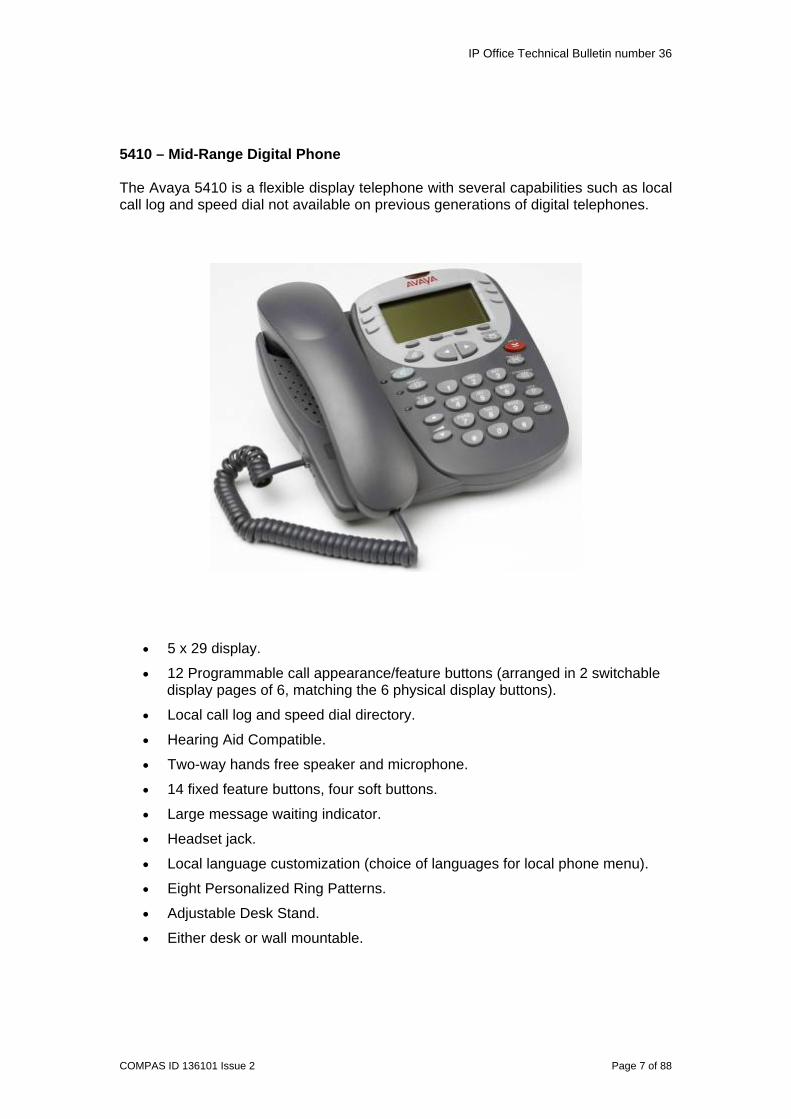
5410 – Mid-Range Digital Phone The Avaya 5410 is a flexible display telephone with several capabilities such as local call log and speed dial not available on previous generations of digital telephones.
• 5 x 29 display.
• 12 Programmable call appearance/feature buttons (arranged in 2 switchable display pages of 6, matching the 6 physical display buttons).
• Local call log and speed dial directory.
• Hearing Aid Compatible.
• Two-way hands free speaker and microphone.
• 14 fixed feature buttons, four soft buttons.
• Large message waiting indicator.
• Headset jack.
• Local language customization (choice of languages for local phone menu).
• Eight Personalized Ring Patterns.
• Adjustable Desk Stand.
• Either desk or wall mountable.

IP Office Technical Bulletin number 36
COMPAS ID 136101 Issue 2 Page 8 of 88
5420 – High End Digital Phone The Avaya 5420 Digital Telephone has an array of convenient features, while supporting expansion capabilities and effective integration with current infrastructure investments. Administration and ongoing maintenance is simplified as the switch automatically performs button labelling. This eliminates the time-consuming and laborious task of using paper labels to denote phone features, and reduces costs when moving phones among users or offices. Additional features such as call logging and a speed-dial directory help enhance overall productivity by providing users with the tools needed for more effective call tracking and faster outbound calling capabilities.
• Large screen 7 line x 29-character display. • 24 Programmable call appearance/feature buttons (arranged in 3 switchable
display pages of 8 matching the 8 physical display buttons). • Local call log and speed dial directory. • Large message waiting indicator. • Headset jack. • Hearing Aid Compatible. • 9 Fixed feature buttons below the display. • 7 Display navigation buttons (4 soft, 3 fixed). • Local language customization (choice of languages for local phone menu). • Eight Personalized Ring Patterns. • Adjustable Desk Stand. • Either desk or wall mountable.

IP Office Technical Bulletin number 36
COMPAS ID 136101 Issue 2 Page 9 of 88
2.2 New IP Phones - 5600 Series Also launched with IP Office 3.0 is a new range of IP Hard phones, the 5600 series, which are SMBS’s own range of IP terminals for the IP Office. These phones are based on the existing 4600 series IP terminals but have been developed specifically for IP Office and will operate ONLY on the IP Office and IP Office Small Office Edition. There are 4 different terminals in the range, the 5601, the 5602, the 5610 and the 5620. 5601 – Basic IP Hard Phone The 5601 IP Telephone is an entry-level telephone with two call appearances, eight fixed feature buttons, and a message-waiting indicator. The 5601 does not support a display, speaker or additional port for connection of an external PC.
• Basic 2 line telephone with no display. • 2 Programmable feature buttons. To ensure correct call handling these
should be programmed as Call Appearance buttons. • Message Waiting Indicator. • 8 fixed feature buttons. • G.711, G.729a/b Voice CODECs. • QoS Options of - UDP Port Selection, DiffServ and 802.1p/B (VLAN). • Single 10/100 BaseT Ethernet port. • Support for Simple Network Management Protocol (SNMP). • Microsoft NetMeeting Compatible. • IP Address Assignment - DHCP only, no support for static addressing. • Downloadable firmware for future upgrades. • Wall Mountable with included desk/wall mount stand. • Hearing Aid Compatible. • Connects to IP Office via the LAN.

IP Office Technical Bulletin number 36
COMPAS ID 136101 Issue 2 Page 10 of 88
5602/5602SW – Basic IP Hard Phone
The 5602 IP Telephone is an entry-level telephone with two programmable call appearance/feature buttons, ten fixed feature buttons, and display. The 5602SW offers the same functionality plus an integrated two-port Ethernet switch.
• 10 Fixed Feature Buttons: Conference, Transfer, Drop, Hold, Redial, Mute,
Volume up & down, Speaker, Voice Mail. • 2 x 24 Character based Eurofont display with 2 programmable feature
buttons. • Message Waiting Indicator. • Call Monitor Speaker (not a speaker phone). • G.711, G.729a/b Voice CODECs. • QoS Options of - UDP Port Selection, DiffServ and 802.1p/q (VLAN). • Single 10/100 BaseT Ethernet port. • Support for Simple Network Management Protocol (SNMP). • Hearing Aid Compatible. • Microsoft NetMeeting Compatible. • IP Address Assignment - DHCP Client or Statically Configured. • Downloadable firmware for future upgrades. • Wall Mountable with included desk/wall mount stand. • Connects to IP Office via the LAN.
The 5602SW includes all of the above features plus an integrated Ethernet switch for PC connection.
• Second full Duplex 10/100 BaseT Ethernet port for PC pass through connection.
• Auto-negotiation provided separately for each port. • 802.3 Flow Control. • Phone has priority over PC port at all times.

IP Office Technical Bulletin number 36
COMPAS ID 136101 Issue 2 Page 11 of 88
5610SW – Mid-Range IP Hard Phone The 5610SW IP Telephone provides a medium screen graphic display, paperless button labels, call log, speed dial, 12 programmable feature buttons, Web browser, and two-way hands free speaker and microphone.
• 9 Fixed Feature Buttons: Conference, Transfer, Drop, Hold, Redial, Mute,
Volume up & down, Speaker, Voice Mail. • Message Waiting Indicator. • Two-way hands free speaker and microphone. • Built-in headset jack. • Built-in language support: English, French, Italian, Spanish & KataKana. • 8 Personalized ring patterns. • G.711, G.729a/b Voice CODECs. • QoS Options of - UDP Port Selection, DiffServ and 802.1p/q (VLAN). • Single 10/100 BaseT Ethernet port. • Support for Simple Network Management Protocol (SNMP). • Hearing Aid Compatible. • Microsoft NetMeeting Compatible. • IP Address Assignment - DHCP Client or Statically Configured. • Downloadable firmware for future upgrades. • Wall Mountable with included desk/wall mount stand. • 5 line x 29-character (168 x 80 4-grayscale) display. • 24 Programmable call appearance/feature buttons (arranged in 4 switchable
display pages of 6, matching the 6 physical display buttons). • 4 Embedded applications: Speed Dial, Call Log, Web Browser (WAP/WML),
Options. • Integrated 2 full duplex 10/100 BaseT switched Ethernet ports for connection
to the IP Office and PC pass through. • Auto-negotiation provided separately for each port. • 802.3 Flow Control. • Phone has priority over PC port at all times. • Connects to IP Office via the LAN.

IP Office Technical Bulletin number 36
COMPAS ID 136101 Issue 2 Page 12 of 88
5620 – High End IP Hard Phone
The 5620 IP Telephone is cost effective and provides a large screen graphic display, paperless button labels, call log, speed dial, 24 programmable feature buttons, Web browser, and two-way hands free speaker and microphone. The 5620 is the only 5600 series IP telephone to support the EU24 (expansion module).
• 24 Programmable call appearance/feature buttons (arranged in 2 switchable
display pages of 12 matching the 12 physical display buttons). • Automatically labelled from the system (no paper labels). • 11 Fixed Feature Buttons: Speaker, Mute, Hold, Headset and Volume
Up/Down, Conference, Transfer, Hold, Redial and Drop. • Large graphical grey-scale display (168 x 132 pixels). • 4 Embedded applications: Speed Dial, Call Log, Web Browser (WAP/WML),
Options. • Two-way hands free speaker and microphone with acoustic cavity for
improved sound quality. • Socket for use with the EU24 expansion module. • 7 Position adjustable desk stand/wall mount stand. • Built-in headset jack. • Built-in language support: English, French, Italian, Spanish & KataKana. • 8 Personalized ring patterns. • Hearing Aid Compatible. • Integrated 2 full duplex 10/100 BaseT switched Ethernet ports for connection
to the IP Office and PC pass through. • Auto-negotiation provided separately for each port. • 802.3 Flow Control. • Phone has priority over PC port at all times. • Connects to IP Office via the LAN.

IP Office Technical Bulletin number 36
COMPAS ID 136101 Issue 2 Page 13 of 88
2.3 Support for 2402 and 2410 Digital Phones IP Office 3.0 will increase the range of existing Avaya digital terminals supported to include the following:
• 2402 Basic Digital Phone (limited support – NO Display support) • 2410 Mid-Range Digital Phone
The Avaya 2400 series adds several enhancements over previous generations of digital telephones. These include paperless button labelling, local call log and speed dial directories, and streamlined styling consistent with Avaya IP telephones. There are currently three models in the 2400 series: the entry-level 2402 Digital Telephone, the mid-level 2410 Digital Telephone, and the high-performance 2420 Digital Telephone (supported in previous IP Office releases). The Avaya 2402 is a cost effective two-wire digital telephone. It is designed to complement the 2410 mid-level and 2420 executive telephones. 2402
• 2-line x 24-character display with two label-less call appearances –
Note: The display on the 2402 (700274590) is NOT Supported on IP Office, only the call functionality of the phone. However a later release of the 2402 phone will support the display on IP Office. • Listen-Only Speaker • 10 Fixed Feature Buttons: Conference, Transfer, Drop, Redial, Speaker,
Message, Hold, Mute, Volume Up & Down, and Feature (to access 12 additional dial pad features).
The 2402 is Hearing Aid Compatible, has a Message Waiting Indicator that flashes when ringing, eight Personalized Ring Patterns and is either desk or wall mountable. The Avaya 2410 is a flexible display telephone with several capabilities such as local call log and speed dial, not available on previous generations of digital telephones. It features: 2410
• 2 x 24 character main display when active, 1 x 24 character main display when idle.
• 6 physical DSS buttons with 13-character soft labels providing 12 logical DSS buttons.
• DSS buttons can present call state icons or feature button status indication.
• IP Office Interactive menus can be invoked from appropriately programmed DSS buttons, and these menus will utilize the 6 DSS buttons and the ‘Exit’ fixed function button.
Avaya 2402
Avaya 2410

IP Office Technical Bulletin number 36
COMPAS ID 136101 Issue 2 Page 14 of 88
2.4 Support for 4601 and 4610 IP Sets IP Office 3.0 will increase the range of existing Avaya IP terminals supported to include the following:
• 4601 - Basic IP Hard phone. • 4610sw - Mid Range IP Hard phone.
The Avaya 4600 Series IP Telephones deliver an extensive set of software features, high audio quality, and attractive streamlined design. Avaya 4600 Series IP Telephones are simple to use with both fixed and flexible feature buttons, easy-to-read graphics, and several wall mount and desk mount options. They have been optimized for reliable use in IP networks, with sophisticated security capabilities such as media encryption and protection from denial of service attacks. Built-in Ethernet switch ports enable streamlined desktop implementations, while voice packets are tagged with the appropriate quality of service (QoS) parameters such as 802.1p/q and DiffServ for priority treatment by QoS-enabled IP networks. The 4600 Series IP Telephones also support the 802.3af power over Ethernet standard. 4601
• Basic 2 line telephone with no display. • 2 DSS buttons with lamps capable of acting as feature
buttons. The 4610sw is intended to bridge the gap between two existing members of the 46xx IP telephony family – the low end 4602 and the higher end 4620. With a 168-by-80 pixel 4-grayscale display, 4 soft buttons, 6 dynamically labeled call appearance/feature buttons, and 4 unique fixed feature buttons: 4610 • 10 x 24 character proportionally spaced main display • 6 physical DSS buttons with 13-character soft labels providing 12 logical DSS
buttons • DSS buttons can present call state icons or feature button
status indication • IP Office Interactive menus can be invoked from
appropriately programmed DSS buttons, and these menus will utilize the 6 DSS buttons and the ‘Exit’ fixed function buttons.
Avaya IP 4610
Avaya IP 4601

IP Office Technical Bulletin number 36
COMPAS ID 136101 Issue 2 Page 15 of 88
2.5 EU24 Expansion Module
This module can expand the Avaya 2420/4620/5420/5620 telephones with 24 additional call appearance/feature buttons. The unit features a large display for button labels. The 24 icons are on display all the time, while a local scroll button allows one of the two banks of 12 labels to be displayed at a time.
• 24 Programmable call appearance/feature buttons. • Automatically labelled from the system (no paper labels). • Connects directly to the associated phone. • Requires a power supply unit (1151B1) for the associated phone and must be
used with the cables supplied. • These units cannot be daisy chained. Only one unit is supported per phone.
2.6 201A Recorder Interface Module The 201A Recorder Interface Module is an adaptor that provides two headset jacks to support the ability to listen in real time to current telephone transactions. A typical real world usage would be within call center environments. It also enables external recording devices with RCA jack connects to be plugged into the recorder module to record telephone transactions. 2.7 Modem 12 Card A new Internal Modem Card with 12 modems is being introduced to replace the existing Modem 2 card to provide dial-up capacity that is better matched to remote access requirements of customers. The Internal Modem card allows up to twelve simultaneous remote access connections into the IP office. The IP403 will support only 4 simultaneous modem connections. The IP406 V2 and IP412 will support all 12 connections. This card is NOT supported on the IP406, only on the new IP406 V2.

IP Office Technical Bulletin number 36
COMPAS ID 136101 Issue 2 Page 16 of 88
3 IP Office Software Enhancements
3.1 Key System Features Key System operation is a fundamental part of business life in the small system market throughout the world. Key system operation relies on having buttons that have indicators, LEDs or Icons, which give the status of the call that the button has been programmed to be associated with. Pressing the button has various actions depending on the state of the call. IP Office 3.0 offers a full range of Key and Lamp features (Call Appearance, Bridged Appearance, Line Appearance and Call Coverage). As the features require a terminal with buttons and LED's or LCD displays the features are only supported on certain terminals in the range of endpoint devices supported on the IP Office. Terminals that support the new features are:
• 24xx series • 44xx series • 54xx series • 64xx series • 46xx series (except for 4601) • 56xx series (except for 5601) • 3810 Wireless Handset • 9040 Transtalk Handset • Spectralink 3616/3626
3.1.1 Call Appearance Call appearance functions are the primary feature of key & lamp operation. A user cannot use the other Key and Lamp features until they have at least one call appearance button programmed. Call Appearance was available pre IP Office 3.0, however its operation has changed.
Call appearance buttons are used to deliver incoming calls that are directed to a users extension number or to a hunt group of which they are a member. Call appearance buttons are also used for outgoing calls and feature (Voicemail, inputting Short Codes etc) calls.
If a user has Call Appearance buttons programmed on their phone then their Call Waiting setting is overridden. The number of Call Appearance buttons that a user has programmed determines the number of calls that they can handle. Forward on busy, if set, is only used when all your Call Appearance buttons are in use.
After upgrading to 3.0 the user will notice that they either have a red LED lit on their phone, an “_” character against the button label if they are using a 24/5400 series phone or a “*” if they have a 46/5602 (against Call Appearance button 1). This indicates Idle Line Preference, please see section 3.1.5 for more details.

IP Office Technical Bulletin number 36
COMPAS ID 136101 Issue 2 Page 17 of 88
Note: When programming Call Appearance buttons the following information should be noted:
• A Call Appearance button must be the first button programmed for the user, followed by any further Call Appearance buttons in a contiguous block. There cannot be a gap between Call Appearance buttons. The manager program will not let you setup Call Appearance buttons that do not adhere to these rules.
• When upgrading from a previous release of IP Office software if there is not a Call Appearance button on the first button then none of your Call Appearance buttons will work. If you add a Call Appearance on button one then all of your other Call Appearances will work regardless of whether they are in a contiguous block. The manager will deny you from adding any further Call Appearance buttons that do not adhere to the new rules.
• If you only have one Call Appearance button you cannot use the transfer button on your phone, as a second Call Appearance button is needed to be able to transfer the call.
• The Avaya 3810 wireless handset has 4 programmable buttons. These are mapped to the users Digital Telephony buttons 1,2,8 and 9. Due to the mapping if you wish to use Call Appearances on all 4 buttons you must program buttons 1 through 9 as Call Appearances. The system will detect the type of phone in use and disable buttons 3-7 from receiving calls. If you skip buttons 3-7 then it will not be possible to program Call Appearances on buttons 8 and 9 as this does not conform to the Call Appearance rules that the buttons must be programmed in a contiguous block.
• The Transtalk 9040 has 8 programmable buttons. Labels 1 to 4 map to the users Digital Telephony buttons 1 to 4 and labels A to D map to buttons 8 to 11. It is only possible to program appearance features on buttons 1,2, 8 and 9 the same as the 3810 wireless handset. If you wish to have 4 Call Appearance buttons then you must program buttons 1 through 9 as Call Appearances, the same as for the 3810. The result of this is that buttons 3 and 4 on the handset will be disabled so cannot be used.
Note: Avaya recommend that only 2 Call Appearance buttons are programmed on the 3810 and 9040.
• Due to the mapping it is only possible to program 4 Call Appearance buttons on these phones (buttons 1 to 4), as it is not possible to conform to the Call Appearance rules that the buttons must be programmed in a contiguous block.
• Previously users with a programmable button set to Self-Administer (Admin) could program their own call appearance buttons. In IP Office 3.0 this is no longer possible. In addition users cannot overwrite buttons already programmed to an appearance function.
• If there are no programmed Call Appearance buttons on your phone then call handling remains the same as in IP Office 2.1 software.

IP Office Technical Bulletin number 36
COMPAS ID 136101 Issue 2 Page 18 of 88
3.1.2 Bridged Appearance A Bridged Appearance is a copy of one of another User’s Call Appearance buttons, it can be used to make or receive calls on behalf of the owner of the Call Appearance. An example of use is boss / secretary working, so the secretary can screen the bosses calls. Calls that are alerting at the Call Appearance alert on the Bridged Appearance at the same time, the ringing cannot be turned off or delayed on Bridged Appearance buttons. Bridged Appearance buttons work in parallel with the Call Appearance button that they are mirroring.
• The Bridged Appearance will only alert if the Call Appearance is alerting. The call can be answered on the Call Appearance or the Bridged Appearance.
• If the Call Appearance is in use, the Bridged Appearance will indicate ‘InUseElsewhere’.
• If the Bridged Appearance is in use, the Call Appearance will indicate ‘InUseElsewhere’.
• If the Bridged appearance user puts the call on hold, the Call Appearance will indicate ‘OnHoldElsewhere’.
• Calls alerting on a Bridged Appearance follow the settings of the original Call Appearance user and not those of the Bridged Appearance user.
• Bridged Appearances to a user who has logged off, or has logged onto a non-multi line phone, will not operate.
• If a user with a Bridged Appearance has DND active the Bridged Appearance button will visually alert when the Call Appearance is alerting.
• You can have multiple Bridged Appearances, but they must each be for a unique User/button combination
Bridging Calls Appearance buttons can also be used to join existing calls and create a conference call. A user can bridge into calls that are shown on their phone as 'InUseElsewhere'. This can be on Call, Bridged or Line Appearances The ability to bridge into calls is controlled by the following feature, which can be set for each IP Office user:
• Cannot be Intruded: Default = On If this option is set for the IP Office user present in the call the longest, no other party can bridge into that call. The “Cannot be Intruded” setting of subsequent users joining the call is ignored.
The exceptions are:
• Voicemail and Conferencing Center calls are treated as Cannot be Intruded at all times regardless of the longest present user.
• When an external call is routed off switch by a user who is no longer in the call, the Cannot be Intruded status used is that of the user who forwarded the call off switch.
• When an external call is routed off switch automatically, for example using a short code in the incoming call route, the call is treated as Cannot be Intruded.
IP Office Technical Bulletin number 36
COMPAS ID 136101 Issue 2 Page 19 of 88
The following also apply:
• Inaccessible You can only bridge into a call that is connected. You cannot bridge into calls still being dialed, ringing or routed.
• IP Office Conferencing Resources The ability to bridge depends on the available conferencing resources of the IP Office system. Those resources are limited and will vary with the number of existing parties in bridged calls and conferences. The possible amount of conferencing resource depends on the IP Office system type.
• Conference Tone When a call is bridged, all parties in the call hear the IP Office conferencing tones. By default this is a single tone when a party joins the call and a double-tone when a party leaves the call. This is a system setting.
Holding a Bridged Call After having bridged into a call, if the user presses hold, their connection to the bridged call (conference) is put on hold. The other parties within the bridged call can continue talking. This will be reflected by the button status indicators. The user who pressed hold will show 'OnHoldHere' on the button they used to bridge into the call. All other appearance users will still show 'in use here'. Note: Bridged Appearances support users on the same system only, they are not supported over a Small Community Network.
3.1.3 Line Appearance A Line Appearance is a representation of a line on the IP Office system, the Line Appearance button tracks the activity on the Line. Only external calls can be answered or made on Line Appearances. All types of PSTN trunks - Analog, Primary Rate and Basic Rate can be assigned to Line Appearances. IP trunks CANNOT function with Line Appearances. Line appearance buttons allow a specific individual line to be used when making calls or answered when they have an incoming call. It also allows users to bridge into calls on a particular line. When making an outgoing call the Line Appearance button is pressed to select the line, the user then dials the number to place the call. No access code is required to make the call. IP Office incoming call routing is still used to determine the destination of all incoming calls. Where Line Appearance buttons have been programmed the call will alert at all phones with that Line Appearance programmed on a button as well as the intended call destination.

IP Office Technical Bulletin number 36
COMPAS ID 136101 Issue 2 Page 20 of 88
Note: When programming Line Appearance buttons the following information should be noted:
• The individual Line Appearance ID numbers are assigned to the trunks through Line programming in Manager. These are different from the Lines Incoming/Outgoing Group IDs, which are now also programmed in a slightly different way. The Line Appearance ID must be a unique number for each channel.
• For the correct operation of Line Appearances, a prefix must be administered for the line and a short code such as [9]N; must also be administered for the Line Appearances to be able to provide secondary dial tone.
The prefix ties the call to the following short codes, which will provide secondary dial tone when the Line Appearance button is pressed.
• Short Code: 9
• Telephone Number: .
• Line Group ID: 2
• Feature: SecondaryDialTone
• Short Code: [9]N;
• Telephone Number: N
• Line Group ID: 2
• Feature: Dial

IP Office Technical Bulletin number 36
COMPAS ID 136101 Issue 2 Page 21 of 88
• If a user with Line Appearances has DND active, the Line Appearance will visually alert when a call is delivered on that line.
• The Cannot Intrude settings of a user determine whether or not someone can pick up a call you hold on a Line Appearance button. If the person placing the call on hold has “Cannot Be Intruded” set then no one else will be able to pick up the call from that Line Appearance button.
• You can have multiple Line Appearance buttons, but they must be for different lines. For example, you can have line appearance buttons for 801, 802, 803, but you can only have line 801 once on your phone.
Note: Line Appearances support lines on the same system only, they are not supported over a Small Community Network.
3.1.4 Call Coverage Call Coverage allows a user to have their calls alert at another users phone if they do not answer and/or when they are not available. The call will ring at the Covered User’s terminal for a configurable amount of time then alert on all terminals that have a Call Coverage button for that user. For example in a sales department, team members may have dedicated lines but if they are unable to answer the call it can ring on the Call Coverage buttons of all the team after the set time. Call Coverage was available pre IP Office 3.0, however its operation has changed. Note: When programming Call Coverage buttons the following information should be noted:
• Due to the new implementation of Call Coverage, now programmed through Digital Telephony, any previous Call Coverage settings in your configuration will be lost during the upgrade. This is because the Coverage form has been removed from the Users configuration. Before upgrading you will need to go through the configuration and make a note of the Call Coverage settings already programmed.
• Call Coverage has been supported in previous releases of IP Office but was setup on the extension that wanted to have its calls ring elsewhere (the Coverage Sender). The programming of Call Coverage is now programmed at the Covering extension (the Coverage Receiver).
• It is now also only possible to cover to extensions that support Key and Lamp functionality. This means you cannot cover to a POT phone or PhoneManager PC Softphone (previously known as iPhoneManager) as these have no concept of button programming, however you can cover for any type of extension.
• The user doing the Covering must have appearance buttons including a Call Coverage appearance button programmed to the Covered users name.

IP Office Technical Bulletin number 36
COMPAS ID 136101 Issue 2 Page 22 of 88
• There is a new Coverage timer introduced in 3.0, the Individual Coverage Time (ICT), which is found in the Users Telephony settings form in Manager. This in conjunction with the existing No Answer Time determines when a call goes to Coverage buttons and Voicemail.
• When a call arrives at the Coverage Sender both timers start. When the ICT
expires the call goes to the Coverage buttons while continuing to alert at the Coverage Sender. When the No Answer Time expires, the call is removed from the Sender and Coverage buttons and goes to Voicemail. These timers are not sequential and the ICT must be less than the No Answer time. We recommend that the ICT be 10 (default) and the No Answer Time be 25 (Default is still 15 seconds) for those users that have Coverage.
• The No Answer timeout should be at least 8 seconds greater than the Individual Coverage Time for the call to ring at the coverage receiver.
• Calls that alert on Call Coverage buttons do not follow the user's forwarding or divert settings.
• If the Coverage Sender is on DND or busy then calls will go to the Coverage buttons immediately and not wait for the ICT to expire. Remember that a user can only be busy when all of their Call Appearance buttons are in use.
• When using Line Appearances the destination of the Incoming Call Route associated with that line determines what coverage calls on that line receive.
• Coverage calls will not be delivered to buttons without LEDs or visual indication. E.g. The last 12 buttons of a 4412.
• A Coverage button is unavailable to accept a call if:
o The user with the Coverage button is logged out. o The user with the Coverage button has DND active. o There is already a call on the Coverage button.
Note: Call Coverage supports users on the same system only, they are not supported over a Small Community Network. Bridged Appearance versus Cover buttons A Bridged Appearance is a 1-1 relationship with a particular Call Appearance. Only calls that ring onto a particular Call Appearance are reflected on a Bridged Appearance button. A Call Coverage button is a many-1 relationship. Any call alerting at a particular extension on any Call Appearance (or Line Appearance where the user is the destination) alert at the cover button.
IP Office Technical Bulletin number 36
COMPAS ID 136101 Issue 2 Page 23 of 88
3.1.5 Idle Line Preference Idle Line Preference (ILP) selects an idle Call or Line Appearance button when there are no alerting calls. This is the button that you will go off hook on if you hit the speaker button or lift the handset. It is indicated on the phones with LEDs by having the red LED on the button on and for the display phones a “_” or “*” indicates this. On Transtalk 9040 phones, the current selected button is indicated by a icon. Note: When programming Idle Line Preference the following information should be noted:
• This feature can be set on or off for each individual user, the default is ON. • For appearance button users with Idle Line Preference OFF, going off-hook
(lifting the handset or pressing SPEAKER, HEADSET, etc) will have no effect until an appearance button is pressed.
• If all the available Call Appearance and Line Appearance buttons are in use, no current selected button choice is made by Idle Line Preference. In this case, going off hook will have no effect.
• The phone user can override Idle Line Preference by pressing an Appearance button. That button will then remain the current selected button while active.
• Idle Line Preference is overridden by Ringing Line Preference if also on for the user.
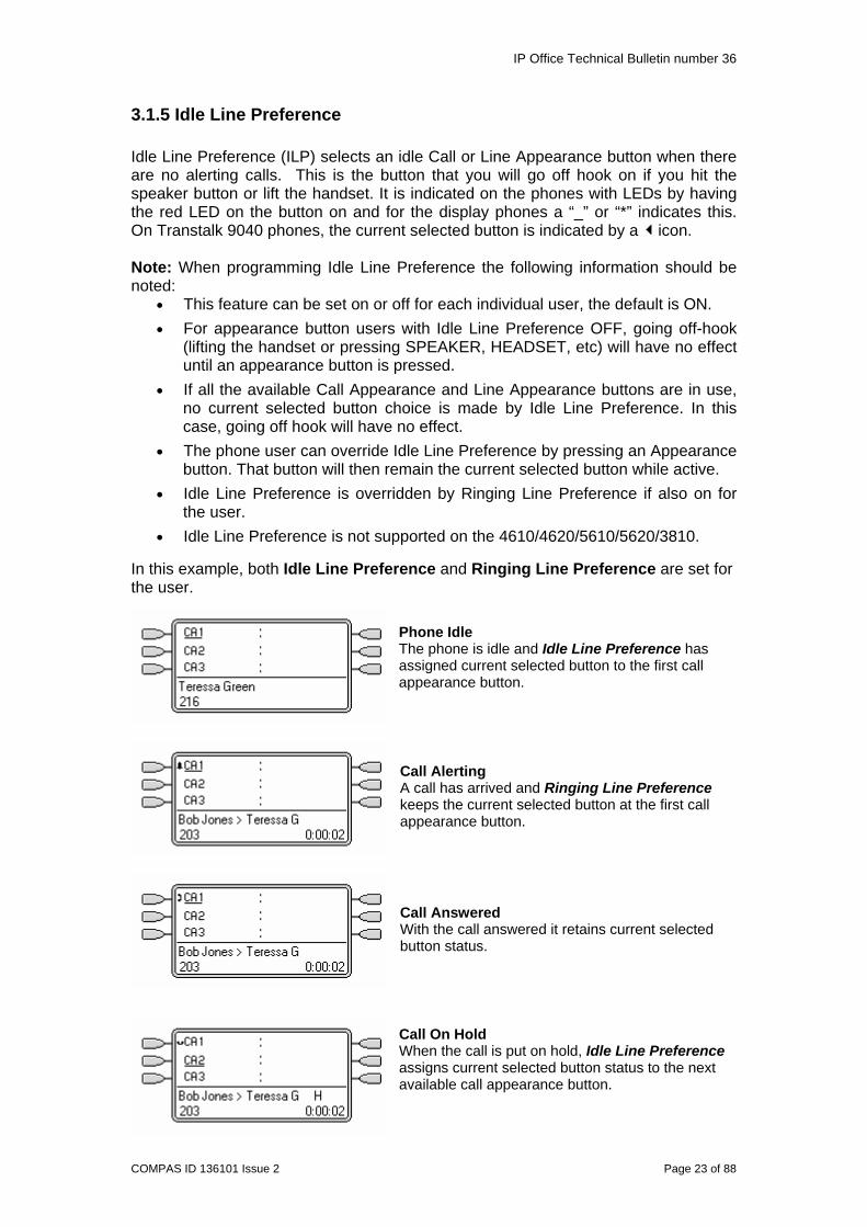
• Idle Line Preference is not supported on the 4610/4620/5610/5620/3810. In this example, both Idle Line Preference and Ringing Line Preference are set for the user.
Phone Idle The phone is idle and Idle Line Preference has assigned current selected button to the first call appearance button.
Call Alerting A call has arrived and Ringing Line Preference keeps the current selected button at the first call appearance button.
Call Answered With the call answered it retains current selected button status.
Call On Hold When the call is put on hold, Idle Line Preference assigns current selected button status to the next available call appearance button.

IP Office Technical Bulletin number 36
COMPAS ID 136101 Issue 2 Page 24 of 88
3.1.6 Ringing Line Preference Ringing Line Preference (RLP) automatically selects a ringing Call Appearance, Line Appearance, Bridged Appearance or Coverage button. This is the call you will answer if you hit the speaker button or lift the handset. It is indicated on the phones with LEDs by having the red LED on the button on and for the display phones an “_” or “*” indicates this. On Transtalk 9040 phones, the current selected button is indicated by a icon. Note: When programming Ringing Line Preference the following information should be noted:
• This feature can be set on or off for each individual user, the default is ON. • For appearance button users with Ringing Line Preference OFF, going off-
hook (lifting the handset or pressing SPEAKER, HEADSET, etc) will not answer the ringing call. A call can only be answered by pressing appearance button.
• Ringing Line Preference overrides Idle Line Preference. • Ringing Line Preference is not supported on the 3810.
Ringing Line Preference Order When a user's longest waiting call alerts on several of the user's appearance buttons and Ringing Line Preference is set for the user, the order used for current selected button assignment is;
1. Call appearance. 2. Bridged appearance. 3. Call coverage. 4. Line appearance.
Idle Line Preference and Ringing Line Preference are set in the Users Telephony settings form in Manager.
Note: Although these are administrable options, it is suggested that they be left as the default (ON).

IP Office Technical Bulletin number 36
COMPAS ID 136101 Issue 2 Page 25 of 88
3.1.7 Hold Functionality Before upgrading to IP Office 3.0 a user could place a call on hold using the hold button and retrieve the call by either pressing hold again or by pressing the Call Appearance button. With 3.0 you must press the Call Appearance button to get the call back, pressing the hold button has no effect. Prior to 3.0 on phones with LEDs the red LED would be on when a call was on hold on a Call Appearance button. With 3.0 the green LED flashes to indicate that the call is on hold and the red LED moves to the next available Appearance button (Idle Line Preference). On the display phones an icon indicates that the call is on hold. Again indication of Idle Line Preference moves to the next available Call Appearance button.
In previous releases a user who had more than one Call Appearance button could place the call on hold automatically by pressing an idle/alerting Call Appearance button. Depending on your system locale this may not now be your default setting.
• If Auto Hold is off, the current call is disconnected. This is the default setting for the US (IP Office system locale enu). If Auto Hold is on, the current call is placed on hold. This is the default setting for all non-US locales.
If you want to change your systems default behavior then Auto Hold can be enabled or disabled from Manager in the System\Telephony form.
3.1.8 LED Feedback Due to the changes made in IP Office 3.0 users who have upgraded from a previous release will notice that the LED states on their phones have changed. As well as the changes they will notice with Idle Line and Ringing Line Preference the following LED feedback has changed. On the 4400/4600 and 6400 series, the green LED now has the following meaning:
• On – The button is in use • Off – The button is idle • Inverse Wink – The call is on hold elsewhere • Flashing – The call is alerting • Flutter – You have put the call on hold

IP Office Technical Bulletin number 36
COMPAS ID 136101 Issue 2 Page 26 of 88
The red LED indicates either the active call when off hook (Ringing Line Preference), or the button you will be active on when going off hook (Idle Line Preference). Definition of Inverse Wink/Flashing and Flutter
• Inverse Wink – 50mS on, 200mS off *----*----*----*---- • Flashing – 500mS on, 500mS off **********---------- • Flutter – 50mS on, 50mS off *-*-*-*-*-*-*-*-*-*-
As well as changing the way that Call Appearance buttons work users will also notice that for User BLF buttons the colors are the reverse of previous releases. So instead of the red LED being on when that user is busy or alerting the green LED will be on. 4400/4600/6400 Series Phone Users Lamp States The table below summarizes the meaning of the twin LED lamp states. Those in bold have either changed or are new in IP Office 3.0. Users of phones with displays will notice very minor changes to button states.
Feature IP Office 2.1 IP Office 3.0
Call Appearance Buttons Lamp State Lamp State
Idle All Off All Off
Idle (ILP On) - Red OnAlerting Green Flash Green Flash
Alerting (RLP On) - Red On, Green Flash InUseHere Green On Red On, Green On InUseElsewhere - Green OnOnHoldHere Red On Green Flutter OnHoldElsewhere - Green Inverse Wink
Other Buttons
ParkedHere Green Flash Green Flash
ParkedElsewhere Red Flash Red Flash
User Ringing Red Flash Green FlashUser In Use Red On Green OnGroup Ringing Green Flash Green Flash
Group Queued Red Flash Red Flash
Toggling Features: On Green On Green On
Toggling Features: Off All Off All Off
Non-Toggling Features All Off All Off Further details of Key and Lamp operation can be found in the manual “IP Office Key and Lamp Operation”.

IP Office Technical Bulletin number 36
COMPAS ID 136101 Issue 2 Page 27 of 88
3.2 Distinctive Ringing Distinctive Ringing is defined as the ability to determine the type of call by the way the phone rings (cadence), for example: Internal / External / Other (Recall, Ringback). On all Avaya digital and IP phones internal and external calls are now indicated by different ring patterns. Distinctive ringing for the call types are predefined on the 2400, 4400, 4600, 5400, 5600, 3810, 9040 and Spectralink phones. The ringing used is appropriate to the locale and cannot be adjusted through the IP Office configuration. The ringer sound may be adjusted through the phone depending on the phone type (Personalised ringing). Distinctive Ringing includes calls alerting on appearance buttons. Distinctive Ringing can only be configured in Manager for analog phones. 3.3 SNMP Alarms for Applications IP Office 2.0 introduced SNMP, in that introduction was a set of entities in the Avaya IPO-MIB that tracks the status of the link between the License Key server and the IP Office. This has been extended in this release with a similar set of entities provided for the Voicemail Lite/VoiceMail Pro Server and Delta Server as follows: The three new SNMP traps that have been implemented are:
1. ipoGenAppEvent (Voicemail only) 2. ipoGenAppFailureEvent (Voicemail and Delta Server) 3. ipoGenAppOperatinalEvent (Voicemail and Delta Server)
More details on setting up these SNMP alarms can be found in the VoiceMail Pro section of this document. 3.4 Embedded Voicemail for IP406v2 With IP Office 3.0 PC-less messaging can be enabled on the IP406v2 by the addition of the new Compact Flash format Embedded Messaging card. This card supports basic Voicemail and Auto Attendant applications. Customers requiring more advanced messaging options can upgrade to VoiceMail Pro and associated feature licenses. Note: The compact flash card in the IP406v2 and Small Office Edition are not hot swappable. Single language sound clips were previously downloaded to the IP Office via TFTP at system start-up from a server PC. However, with the multi-language clips this would be too lengthy a process. The sound clips for all languages, in the correct format, are therefore now supplied pre-loaded onto the Compact Flash Cards.

IP Office Technical Bulletin number 36
COMPAS ID 136101 Issue 2 Page 28 of 88
The Embedded Voicemail and Auto-Attendant applications are based on those originally implemented on Small Office Edition, with the following enhancements:
• Default message length - increased to 2 minutes, configurable to a maximum of 3 minutes. This is set in Manager in the System\Voicemail form. This option will only be displayed when Voicemail type “Integral” is selected. This is set in the range 5 to 180 seconds.
• Auto-attendant time-out - in the absence of DTMF input the caller will time-out to a pre-defined position. Following the playing of the auto attendant prompts the auto-attendant will wait 8 seconds for a button press. If the auto attendant was accessed via an Incoming Call Route with a Fallback Destination set inactive callers are transferred to that destination, otherwise the caller is disconnected. IP Office 3.0 allows the auto attendant timeout to be adjusted within the system configuration. This is set in the range 5 – 20 seconds.
• Remote Voicemail access - no longer requires complex configuration.
• 15 hour storage time
• 4 ports for four simultaneous messaging users
• No VCM needed
Note: Embedded Voicemail does not support Centralized Voicemail.
3.5 Enhancements to Small Office Edition Embedded Voicemail With IP Office 3.0 the Small Office Edition Embedded Voicemail will still be provided through the existing 64 Megabyte PCMCIA card, however, the Voicemail options on the card have been updated to provide the following features as per the IP406v2 Embedded Voicemail:
• Default message length.
• Auto attendant timeout.
• Remote access to Voicemail.
Note: The method of transferring and handling prompts has changed in IP Office 3.0. Prompts are no longer transferred from a Manager PC using TFTP following a system restart. For existing systems with Embedded Voicemail, the Voicemail will be inactive following the IP Office control unit being upgraded to 3.0. To reactivate the Embedded Voicemail the new 3.0 prompt set needs to be loaded onto the memory card. Please see the upgrade instructions in the Technical Notes section of this document for further details.
SNMP Disk Full Warning
On IP Office systems configured for SNMP, a storage nearly full alarm is generated when the Embedded Voicemail memory card reaches 90% full. A storage full alarm is generated at 98% full for the Small Office Edition and 99% full for the IP406v2.

IP Office Technical Bulletin number 36
COMPAS ID 136101 Issue 2 Page 29 of 88
3.6 Changes in Manager
• When programming Call Appearance keys for a User if they have Busy on Held set when you come out of their configuration Manager will ask if you want to “Clear Busy on Held for this User? Call Appearances have been programmed”. If you choose not to accept this clear the option for Busy on Held then the user will not be able to receive any further calls if their existing call is placed on hold.
• In Manager a new option has been added to the VOIP form of an IP Extension. There is now an option called “Gain” which allows you to alter the volume received on an IP Phone. The gain is selectable from –31dB to +31dB in 1dB increments.
4 IP Office VoiceMail Pro
4.1 Personal Distribution Lists Personal distribution lists allow a user to send a message to a list of users simultaneously. The creation, management and usage of the personal distribution lists is either via the phone or through PhoneManager Pro once a user has logged into their mailbox. Lists cannot be viewed or controlled from within the VoiceMail Pro Client. Each mailbox user can create up to 20 lists, each containing up to 360 mailbox numbers. These lists can then be used when forwarding or sending messages from within the mailbox. Each list can be marked as private or public. If private, the mailbox that owns the list will be the only user that can access the list. Public lists can be used by other mailbox users when forwarding or sending messages. A user can also import the contents of a public list into one of their own lists. Public lists remain the ownership of

IP Office Technical Bulletin number 36
COMPAS ID 136101 Issue 2 Page 30 of 88
the user who created them but can be accessed as read only by any other mailbox user on the local system. If VoiceMail Pro Networked Messaging (VPNM) is installed then lists can include mailboxes on remote systems. The only difference is that where the mailbox user name is used to identify local mailboxes in a list remote mailboxes are listed by number only. When creating and managing distribution lists through the phone, selecting menu option 5 within the mailbox will give you access to the Personal Distribution list menus. Context sensitive help will be available throughout administering the lists through the use of the button sequence *4. For full details of Personal Distribution List operation please refer to the Intuity Mailbox User Guide. This subject is also covered in the PhoneManager section of this document. Note: Personal distribution lists are only available to mailbox users when VoiceMail Pro is running in Intuity mode. 4.2 Group Message Broadcast When a message is left for a hunt group prior to 3.0 IP Office would notify all group members that a message has arrived. When any member retrieves this message the message notification is turned off for all group members. A new broadcast option has been added in 3.0 to the Hunt Group Voicemail form in Manager, which alters the operation so that message notification will only be turned off for each hunt group member when they retrieve the message.
If a Voicemail message is left for a hunt group and Broadcast is enabled, a copy of the message is forwarded to the mailbox of all the group members. The original message in the hunt group mailbox will then be automatically deleted. If Broadcast is not turned on there will be no change to hunt group message notification and message delivery to group members will operate as per current IP Office operation. The default setting will be for Broadcast messages to be turned off.
IP Office Technical Bulletin number 36
COMPAS ID 136101 Issue 2 Page 31 of 88
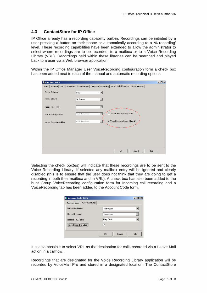
4.3 ContactStore for IP Office IP Office already has a recording capability built-in. Recordings can be initiated by a user pressing a button on their phone or automatically according to a ‘% recording’ level. These recording capabilities have been extended to allow the administrator to select where recordings are to be recorded, to a mailbox or to a Voice Recording Library (VRL). Recordings held within these libraries can be searched and played back to a user via a Web browser application. Within the IP Office Manager User VoiceRecording configuration form a check box has been added next to each of the manual and automatic recording options.
Selecting the check box(es) will indicate that these recordings are to be sent to the Voice Recording Library. If selected any mailbox entry will be ignored and clearly disabled (this is to ensure that the user does not think that they are going to get a recording in both their mailbox and in VRL). A check box has also been added to the hunt Group VoiceRecording configuration form for Incoming call recording and a VoiceRecording tab has been added to the Account Code form.
It is also possible to select VRL as the destination for calls recorded via a Leave Mail action in a callflow. Recordings that are designated for the Voice Recording Library application will be recorded by VoiceMail Pro and stored in a designated location. The ContactStore
IP Office Technical Bulletin number 36
COMPAS ID 136101 Issue 2 Page 32 of 88
application will periodically monitor this designated storage area for new files. On finding new completed recordings the application will relocate these files into its own file structure and make these recordings available through its Web based browser applications. The following information is stored for each call:
• A unique reference for the recording • The start date and time • The duration of the recording • The name and number of the parties on the call—where this was available to
IP Office (through ANI, CLI or DNIS) at the time of the call. • The direction of the call (incoming, outgoing, or internal) • The owner of the recording. • The target or dialed number, which may be different from the number that
actually took the call. Within the VoiceMail Pro GUI, System Preferences, General tab, a new entry has been provided to define the total recording time for any individual Voice Recording. This will be a global setting for all VRL call recordings. The maximum allowed recording time is 60 minutes. Recordings are stored as industry standard WAV files in a hierarchical directory structure. These files are compressed using G.726 16kbps ADPCM, as a result storage requirements on the server are approximately 8MB per hour of storage. ContactStore includes an administration application that is accessible only to specified administrators and is accessed through an Internet Explorer 5.0 or higher browser. The pages in this web application are used to maintain, update, and monitor the system. There is also an application for performing the Search and Replay of the recordings, again this is accessed through a web browser. The Search and Replay web page downloads an ActiveX control, which it uses to decompress the audio for replay. If your default security settings prohibit downloading such controls, you need to provide a means of getting the ActiveX control to your users' desktops. Internet Explorer (IE) determines rights by putting web servers into zones and then granting those zones specific rights. To access and use the page, the zone needs the following rights:
• Run ActiveX controls and plug-ins • Script ActiveX controls marked safe for scripting • Active Scripting • Download signed ActiveX controls
Your Intranet zone and/or the Trusted Site zone may already be assigned these rights. If so, you need to verify that the ContactStore is in one of these zones. The hard disk has limited storage capabilities so once the available hard disk space is used the oldest recordings will be deleted automatically. To keep copies of recordings or to protect the recordings in the event of failure/theft/destruction of the hard disk on the recorder or to provide longer-term archive and replay capability, you can use a DVD+RW drive within the ContactStore server.

IP Office Technical Bulletin number 36
COMPAS ID 136101 Issue 2 Page 33 of 88
Once VRL has been installed and the application runs it will verify that a license exists within IP Office for VRL. If a license does not exist the system will still continue to operate for 45 days. If no license exists after this date the ContactStore will cease operation until a license is added. Any recordings that have been taken during this trial period will be made available again when a valid license is added. The ContactStore user will be informed of the license status and expiry date. Note: When setting up ContactStore the following information should be noted:
• For ContactStore to work a valid VMPro Recordings Administrators license must be entered into the IP Office configuration.
• The application must be configured to store the recordings on a separate partition, drive or PC from the VoiceMail Pro. This is necessary to ensure that the long-term storage of recording archives and space available for mailbox messages do not conflict.
• The current recording facilities offered by IP Office is not able to guarantee that calls will be recorded, as a result this release of Voice Recording will not provide legal quality Total/Bulk recording facilities.
• The “Parties” search filter requires a “)” to return records • A minimum of 20GB of disk space is recommended. Allow for at least 10GB
of recordings (over 1000 hours of audio) to be held online. Further information on ContactStore can be found in the following documents:
• IP Office ContactStore System Admin • IP Office ContactStore Pre-requisites Guide • IP Office ContactStore Installation Manual • IP Office ContactStore Search and Reply Instructions
4.4 Fax Server Support Fax is a significant part of how customers do business. Customers are therefore demanding better ways of managing their Fax traffic. The ability to automatically detect and route an incoming Fax call within an Auto Attendant was implemented in VoiceMail Pro 2.0 and extended in 2.1 to include a subscriber’s Voicemail box. VoiceMail Pro 3.0 has been verified for operation against a number of leading Fax server products.
System overview
IP Office Technical Bulletin number 36
COMPAS ID 136101 Issue 2 Page 34 of 88
The Fax servers verified with IP Office VoiceMail Pro 3.0 are: Equisys - Zetafax
• Zetafax provides versatile network fax software solutions for small businesses, corporate offices and distributed enterprise businesses. It enables employees to send and receive faxes at their desktop, without the need to print fax communications, take them to a fax machine and send them manually. Zetafax can be seamlessly integrated into market leading email systems like Exchange allowing users to send and receive faxes directly from their Outlook client. In addition Zetafax can be integrated with other existing applications, such as accounting or CRM systems, for fast, automated faxing from the desktop or back office. More than 60,000 customers already use Zetafax worldwide. Further product information is available from www.equisys.com
Captaris - RightFax
• RightFax offers a broad, scalable product line that integrates with email, desktop, CRM, ERP, document management, imaging, archival, call center, copier/scanner systems, as well as host, legacy and mainframe applications, virtually all business applications. Further product information is available from www.captaris.com
Fenestrae – Faxination
• Fenestrae Faxination Server for Microsoft Exchange integrates fax into email technology. Create faxes on your desktop and deliver them to your chosen fax machine at the click of a mouse. Further product information is available from www.fenestrae.com
GFI - GFI FAXMaker
• GFI FAXMaker for Exchange/SMTP allows users to send and receive faxes and SMS/text messages directly from their email client. It integrates with Active Directory and therefore does not require the administration of a separate fax user database. GFI FAXMaker integrates via the SMTP/POP3 protocol with Lotus Notes and any SMTP/POP3 server. Further product information is available from www.gfi.com
Note: If you are already using a Fax server with a previous release of IP Office software when you upgrade to 3.0 you may need to change the settings of the fax server extension ports or you may encounter problems with the routing of faxes. If you are using the VoiceMail Pro to route faxes to the fax server then the “Caller Display Type” for the fax server extensions needs to be set to DTMFB (this is the current method of working in 2.x). If you are routing faxes directly to the fax server ports using DDI\DID then the Caller Display type needs to be changed to DTMFF. Further details on Fax Server Integration can be found in IP Office 3.0 VoiceMail Pro Installation and Admin Manual.
IP Office Technical Bulletin number 36
COMPAS ID 136101 Issue 2 Page 35 of 88
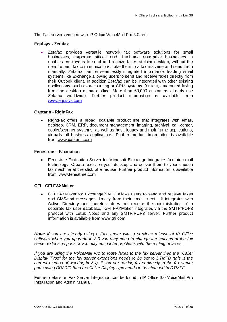
4.5 SNMP Alarms The IP Office system can be configured to send SNMP (Simple Network Management Protocol) alarms. When this is configured the VoiceMail Pro server can tell the IP Office system when to send SNMP alarms about its available disk space. Within the VoiceMail Pro GUI the Alarm Threshold can be set.
The Alarm Threshold Level Sets the number of units left (minutes or MB) at which point the SNMP alarm is triggered. The minimum setting is 11. There are three different levels of alarm that are sent based on the setting of the alarm threshold level. The three different thresholds based on the default setting are:
1. Storage Nearly Full = 60Mb (or Alarm Threshold Level) 2. Storage Full = 30Mb 3. Storage OK = 90Mb
Once you change the Alarm Threshold level you need to be aware of how the other threshold values change. Storage OK always equates to the Storage Nearly Full value + 30. Storage Full is worked out as follows:
• If the current value of Storage Full > Storage Nearly Full -10 then the Storage Full value is changed to Storage Nearly Full -10.
• If the current value of Storage Full <= Storage Nearly Full -10 then the
Storage Full value remains unchanged.

IP Office Technical Bulletin number 36
COMPAS ID 136101 Issue 2 Page 36 of 88
Example 1: You change the value of the Alarm Threshold to 50Mb. The values you now have are:
1. Storage Nearly Full = 50Mb 2. Storage Full = 30Mb 3. Storage OK = 80Mb
In this example the current value of Storage Full (30mb) <= to the value of Storage Nearly Full -10 (40Mb) so the value remains unchanged. Example 2: You change the value of the Alarm Threshold to 30Mb. The values you now have are:
1. Storage Nearly Full = 30Mb 2. Storage Full = 20Mb 3. Storage OK = 60Mb
In this example the current value of Storage Full (30mb) > than the value of Storage Nearly Full -10 (20Mb) so the value changes to Storage Nearly Full -10 (20Mb). Example 3: You change the value of the Alarm Threshold to its lowest level 11Mb. The values you now have are:
1. Storage Nearly Full = 11Mb 2. Storage Full = 1Mb 3. Storage OK = 41Mb
In this example the current value of Storage Full (20mb) > than the value of Storage Nearly Full -10 (1Mb) so the value changes to Storage Nearly Full -10 (1Mb). Once you have got to this position if you then decide to increase your Storage Nearly Full level then the Storage Full level is not going to change from 1Mb. Example 4: You change the value of the Alarm Threshold to 80Mb. The values you now have are:
1. Storage Nearly Full = 80Mb 2. Storage Full = 1Mb 3. Storage OK = 110Mb
In this example the current value of Storage Full (1mb) <= to the value of Storage Nearly Full -10 (70Mb) so the value remains unchanged at 1Mb. To be able to increase the Storage Full threshold you should first click on the default settings button in the SNMP alarm form, which will set the threshold back to its default of 30Mb, and then change your Alarm Threshold level to the appropriate value.

IP Office Technical Bulletin number 36
COMPAS ID 136101 Issue 2 Page 37 of 88
5 IP Office Conferencing Center
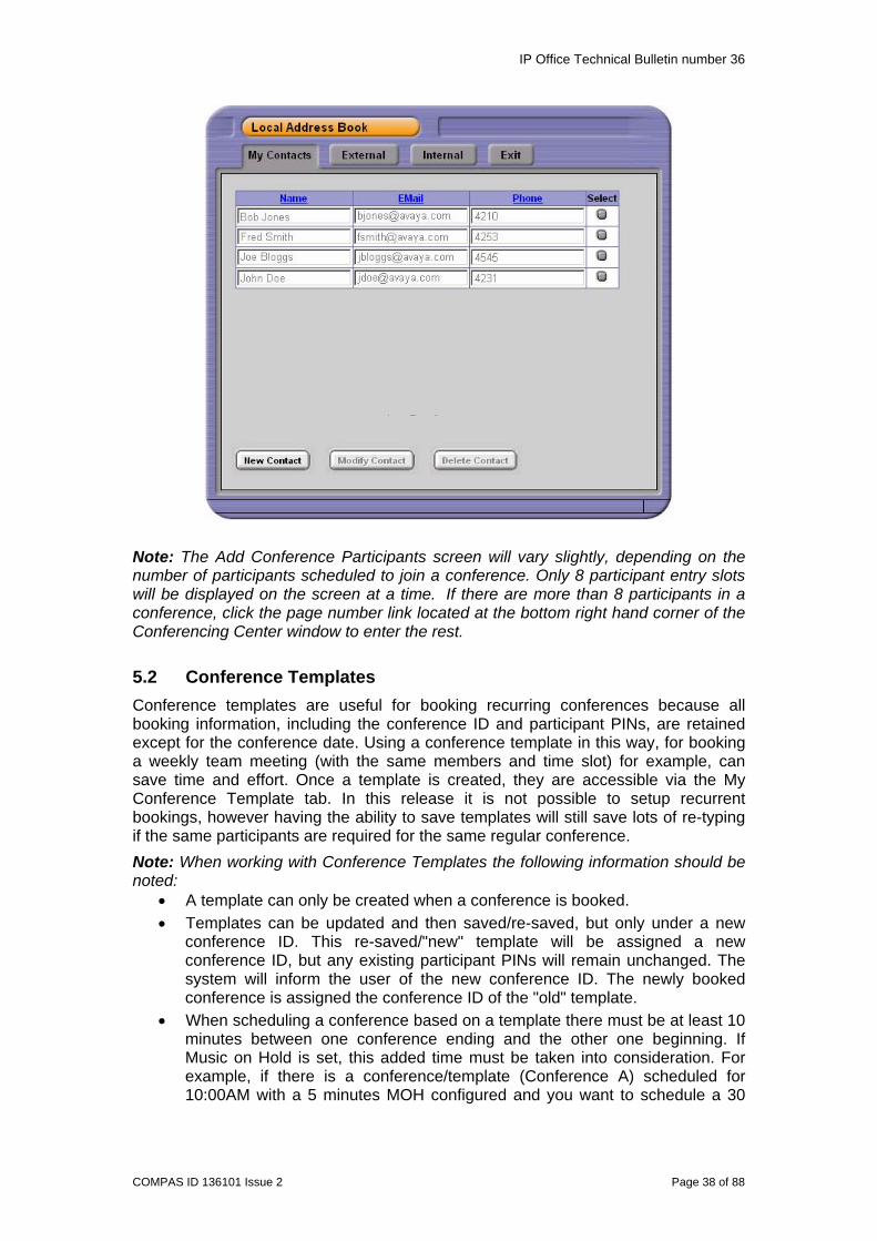
5.1 Local Address Book The user list within the Web Scheduler has been modified to show remote users in the IP Office user directory, if an IP Office Small Community Network (SCN) has been set up. At present, adding a user from the IP Office database only sees this from the host IP Office. It is not possible to build the remote users database on alternative Voice Networked connected IP Offices. Users can also be selected from a user defined contact list. The user defined list can be modified but the IP Office derived lists cannot be changed. When booking a conference it is possible to add a contact from any one of three lists.
In the Web Scheduler the IP Office external directory can be used to enter name, phone number and email information when adding external participants. When an email address is typed in the Web Scheduler, it will be automatically saved against the participant name to avoid having to retype it in future. A local directory for new contacts will be built up on the Conferencing Center server. New participant details (Name, Phone number and Email) booked for a conference will be stored in the IP Office Conferencing Center local directory under “My Contacts” for that user profile. Stored contact details can be retrieved by selecting a participant in the directory list after clicking on the “Select User” icon in the Web Scheduler. The user will be able to add, modify or delete contact details in the “My Contacts” directory.
IP Office Technical Bulletin number 36
COMPAS ID 136101 Issue 2 Page 38 of 88
Note: The Add Conference Participants screen will vary slightly, depending on the number of participants scheduled to join a conference. Only 8 participant entry slots will be displayed on the screen at a time. If there are more than 8 participants in a conference, click the page number link located at the bottom right hand corner of the Conferencing Center window to enter the rest. 5.2 Conference Templates Conference templates are useful for booking recurring conferences because all booking information, including the conference ID and participant PINs, are retained except for the conference date. Using a conference template in this way, for booking a weekly team meeting (with the same members and time slot) for example, can save time and effort. Once a template is created, they are accessible via the My Conference Template tab. In this release it is not possible to setup recurrent bookings, however having the ability to save templates will still save lots of re-typing if the same participants are required for the same regular conference. Note: When working with Conference Templates the following information should be noted:
• A template can only be created when a conference is booked. • Templates can be updated and then saved/re-saved, but only under a new
conference ID. This re-saved/"new" template will be assigned a new conference ID, but any existing participant PINs will remain unchanged. The system will inform the user of the new conference ID. The newly booked conference is assigned the conference ID of the "old" template.
• When scheduling a conference based on a template there must be at least 10 minutes between one conference ending and the other one beginning. If Music on Hold is set, this added time must be taken into consideration. For example, if there is a conference/template (Conference A) scheduled for 10:00AM with a 5 minutes MOH configured and you want to schedule a 30
IP Office Technical Bulletin number 36
COMPAS ID 136101 Issue 2 Page 39 of 88
minute conference (Conference B) just before Conference A, then the latest it can be scheduled (if using Conference A's template) is 9:15AM.
• The user will be able to save up to 20 conference templates. The user will also be able to delete templates that are no longer required.
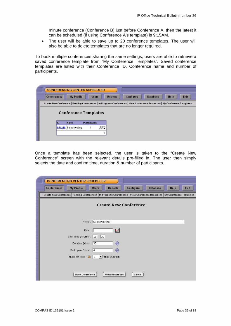
To book multiple conferences sharing the same settings, users are able to retrieve a saved conference template from “My Conference Templates”. Saved conference templates are listed with their Conference ID, Conference name and number of participants.
Once a template has been selected, the user is taken to the “Create New Conference” screen with the relevant details pre-filled in. The user then simply selects the date and confirm time, duration & number of participants.

IP Office Technical Bulletin number 36
COMPAS ID 136101 Issue 2 Page 40 of 88
5.3 Installation Enhancements IP Office Conferencing Center 2.1 required a local web server running Microsoft IIS. To allow the web support facility to be used by external participants, the web conference site can now be hosted in the DMZ / ISP web server (not the booking site - this should always be internal). The Web Client Conferencing application can be installed as a separate option (in 2.1 it is not). The Conferencing booking site (Scheduler) is only supported on customers’ premises. Full Install is for installing Conferencing Center in just one location the same as in 2.1. The Web Booking install is for installing the scheduler part of Conferencing Center – this should be local to the IP Office. The Web Client Host install is for installing the Web Client side of Conferencing Center. This install asks for the location of the booking scheduler and then links remotely to it. Note: The web site uses the web services to communicate with the Conference server and enables the use of a SSL link to protect the traffic. 6 IP Office User Applications
6.1 PhoneManager
6.1.1 Profiles Users Preferences and PhoneManager configuration (including layout, speed dials, directory, and other associated user information) are now saved into a Profile. These settings by default are saved to the current “My Documents\Avaya\IP 400\PhoneManager\Profile” folder. Profiles can be saved to another location if required, either on your local drive or on your Local Area Network (LAN). The profile is saved as an xml file. This file can also be loaded onto another PC running PhoneManager if the file is accessible from that PC. Note: The name of the profile must match your extension number. PhoneManager will prevent you from loading a profile saved with a different extension number. (Example: Extension 201 profile is called 201.xml)
6.1.2 Compact Mode (Pro Only) Compact Mode is a configurable item within the PhoneManager Pro preferences. Users can select whether or not the application will initialise in a minimal "compact" or "full" mode. While in Compact Mode, a notification slider alerts you to new calls and allows the user to view the caller ID or associated caller’s name and answer the call.

IP Office Technical Bulletin number 36
COMPAS ID 136101 Issue 2 Page 41 of 88
Users can easily switch between Standard & Compact Mode. When an incoming call arrives, the tray icon blinks so that there is some indication even if the window is not visible. When the user has finished the call they can then click the Slider "Hang Up" button. This closes the Slider and keeps the application in Compact Mode.
6.1.3 Speed Dial Enhancements A number of enhancements have been made to speed dial entries within PhoneManager. It is now possible to set a speed dial entry as either Internal or External. Speed dials have also been enhanced to allow multiple phone numbers to be stored against each individual speed dial. Depending on the type of speed dial and its default number setting a different icon will be used to denote the type of speed dial. Note: PhoneManager Pro supports 1000 speed dial entries, PhoneManager Lite supports 15 speed dial entries. .
Internal Speed Dial (If instant messaging is enabled for the user the icon will be green)
For an Internal speed dial it is possible to store Name, Number, Home Phone, Mobile and PIN against the speed dial entry. By default the number stored in the “Number” field is the number used to make a call if you double click on the speed dial entry. The default number cannot be changed for an Internal speed dial. If you want to call a different number you can right click on the speed dial and can then select Call and the number you want to call (Number\Home Phone or Mobile). For External speed dial entries it is also possible to store a fax number against the speed dial entry. You can also select which number is the default number to be dialled if you double click the speed dial entry.

IP Office Technical Bulletin number 36
COMPAS ID 136101 Issue 2 Page 42 of 88
Different icons are displayed for external speed dial numbers depending on the default number that has been set.
External Speed Dial – Work Number set as default
External Speed Dial – Home number set as default
External Speed Dial – Mobile number set as default
External Speed Dial – Fax number set as default
When running PhoneManager in Pro mode only it is also possible to create Speed Dial Groups, these appear as separate tabbed views in the main window. This provides a convenient way to manage your speed dials, for example you could group them by department.
Note: The total number of groups that a user can program within PhoneManager Pro is 10.
The speed dial tab of PhoneManager now also incorporates a Phone Dialer. The Phone Dialer allows you to dial from the PhoneManager application. You can turn off the Phone Dialer by right clicking in the Phone Dialer window and selecting Hide Phone Dialer.
6.1.4 Personal Distribution List Support (Pro Only) VoiceMail Pro provides the ability to set-up Personal Distribution Lists for users, with up to 20 lists of 360 members per list. The creation and management of Personal Distribution Lists is simplified through the use of PhoneManager Pro. The lists are accessed through the Voicemail tab in preferences.

IP Office Technical Bulletin number 36
COMPAS ID 136101 Issue 2 Page 43 of 88
6.1.5 Microsoft LIVE Communication Server Support PhoneManager 3.0 provides support for Instant Messaging with the Microsoft Live Communication Server (LCS). This allows instant messaging to occur between internal contacts using the Microsoft Live Communication Server. Within Preferences a new configuration tab has been added to allow the necessary parameters to be setup.

IP Office Technical Bulletin number 36
COMPAS ID 136101 Issue 2 Page 44 of 88
Enable Instant Messaging Support: Check this box to enable Instant Messenger Support. If you have connection to a Microsoft Live Communication Server you will need to check this box for other users to add you as a Instant Message User. Server: Enter the Server name of the Microsoft Live Communication Server. User name: Enter your email account and domain as configured on the Microsoft Live Communication Server. e.g. [email protected] Protocol: From this drop down list. Select the Protocol you are using to connect to the Microsoft Live Communication Server. You can choose from TCP, UDP and TLS. Password: Enter your password associated with your Instant Message profile. Password Check Box: Check this box for Phone Manager to remember your password. You will not have to re-enter your password if this box is checked. When you select this option a chat window opens allowing you to type in and send your message.
You can send an Instant Message to a User through the Speed Dial icons in the Speed Dial Pane. If a user has Instant Messaging enabled their icon will be green.
If you right click on the speed dial icon you have an option to “Send an Instant Message”.

IP Office Technical Bulletin number 36
COMPAS ID 136101 Issue 2 Page 45 of 88
Note: Both Users need to have Instant Messaging enabled to send an Instant Message.
6.1.6 Drag and Drop Functionality Drag and Drop functionality makes it easy to call and conference users. By definition this is the ability to drag names, numbers, and icons into the Call Status pane or Dial fields to make a call. For example you can make a call simply by dragging a speed dial entry into the Call Status area of the main window. When a user on an active call drags and drops another call onto that currently active call PhoneManager will create a conference call between the selected parties.
6.1.7 Import/Export of Local Directories (Pro Only) Directory entries are used to store regularly dialled internal or external numbers. They can also be used to match the CLI or DDI\DID of incoming calls to a name. When running PhoneManager in Pro mode only it is possible to export the directory or import a correctly formatted CSV file or previously exported directory.
6.1.8 Call History Enhancements (Pro Only) The Call History area of PhoneManager Pro has been enhanced to show the following information:
• Call Duration • Hold Time • Ring Time • For missed call entries the date and time the call was missed is shown
It is also possible to perform a column sort in the call history window by clicking on the relevant column name. A sort can be performed on all columns.
6.1.9 Programmable Date and Time Format (Pro Only) The Date and Time settings tab in preferences allows you to customize the date as it is displayed in the PhoneManager call history window. You can specify between the Windows default format, based upon your operating system and region, or choose custom date formats. It is also possible to select either a 24-hour clock or one stipulating AM and PM.
The speed dials have tool tips, which are displayed when your mouse pointer is held over one of the speed dial entries, these display the presence state of a user. The only presence states that are supported in this release are Online or Offline.
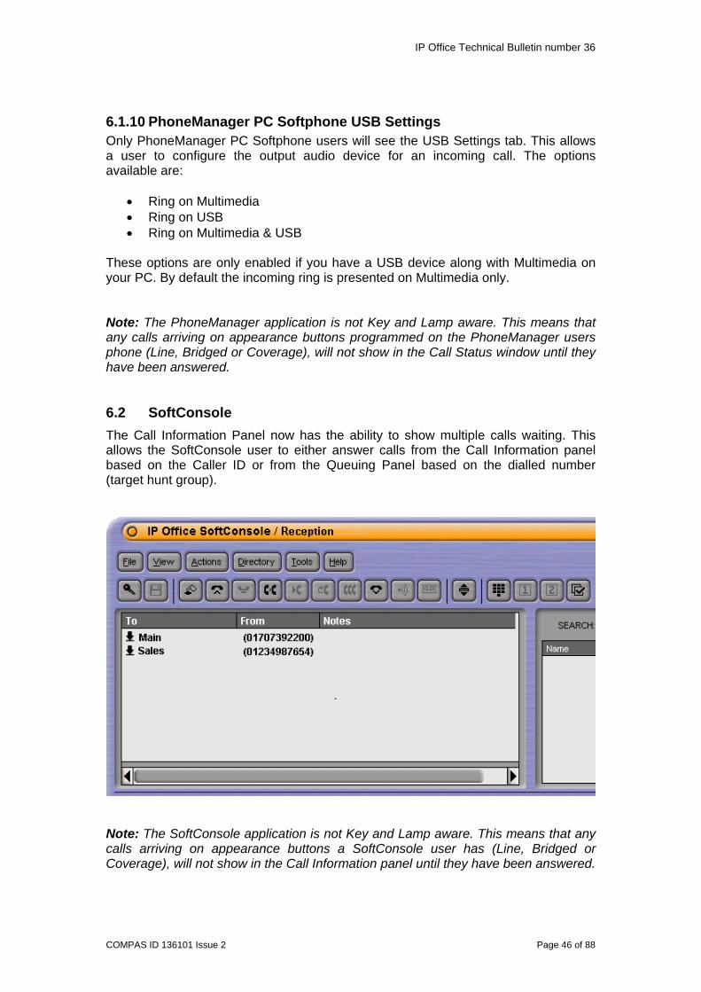
IP Office Technical Bulletin number 36
COMPAS ID 136101 Issue 2 Page 46 of 88
6.1.10 PhoneManager PC Softphone USB Settings Only PhoneManager PC Softphone users will see the USB Settings tab. This allows a user to configure the output audio device for an incoming call. The options available are:
• Ring on Multimedia • Ring on USB • Ring on Multimedia & USB
These options are only enabled if you have a USB device along with Multimedia on your PC. By default the incoming ring is presented on Multimedia only. Note: The PhoneManager application is not Key and Lamp aware. This means that any calls arriving on appearance buttons programmed on the PhoneManager users phone (Line, Bridged or Coverage), will not show in the Call Status window until they have been answered.
6.2 SoftConsole The Call Information Panel now has the ability to show multiple calls waiting. This allows the SoftConsole user to either answer calls from the Call Information panel based on the Caller ID or from the Queuing Panel based on the dialled number (target hunt group).
Note: The SoftConsole application is not Key and Lamp aware. This means that any calls arriving on appearance buttons a SoftConsole user has (Line, Bridged or Coverage), will not show in the Call Information panel until they have been answered.
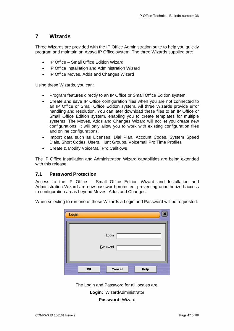
IP Office Technical Bulletin number 36
COMPAS ID 136101 Issue 2 Page 47 of 88
7 Wizards Three Wizards are provided with the IP Office Administration suite to help you quickly program and maintain an Avaya IP Office system. The three Wizards supplied are:
• IP Office – Small Office Edition Wizard • IP Office Installation and Administration Wizard • IP Office Moves, Adds and Changes Wizard
Using these Wizards, you can:
• Program features directly to an IP Office or Small Office Edition system • Create and save IP Office configuration files when you are not connected to
an IP Office or Small Office Edition system. All three Wizards provide error handling and resolution. You can later download these files to an IP Office or Small Office Edition system, enabling you to create templates for multiple systems. The Moves, Adds and Changes Wizard will not let you create new configurations. It will only allow you to work with existing configuration files and online configurations.
• Import data such as Licenses, Dial Plan, Account Codes, System Speed Dials, Short Codes, Users, Hunt Groups, Voicemail Pro Time Profiles
• Create & Modify VoiceMail Pro Callflows The IP Office Installation and Administration Wizard capabilities are being extended with this release. 7.1 Password Protection Access to the IP Office – Small Office Edition Wizard and Installation and Administration Wizard are now password protected, preventing unauthorized access to configuration areas beyond Moves, Adds and Changes. When selecting to run one of these Wizards a Login and Password will be requested.
The Login and Password for all locales are:
Login: WizardAdministrator
Password: Wizard
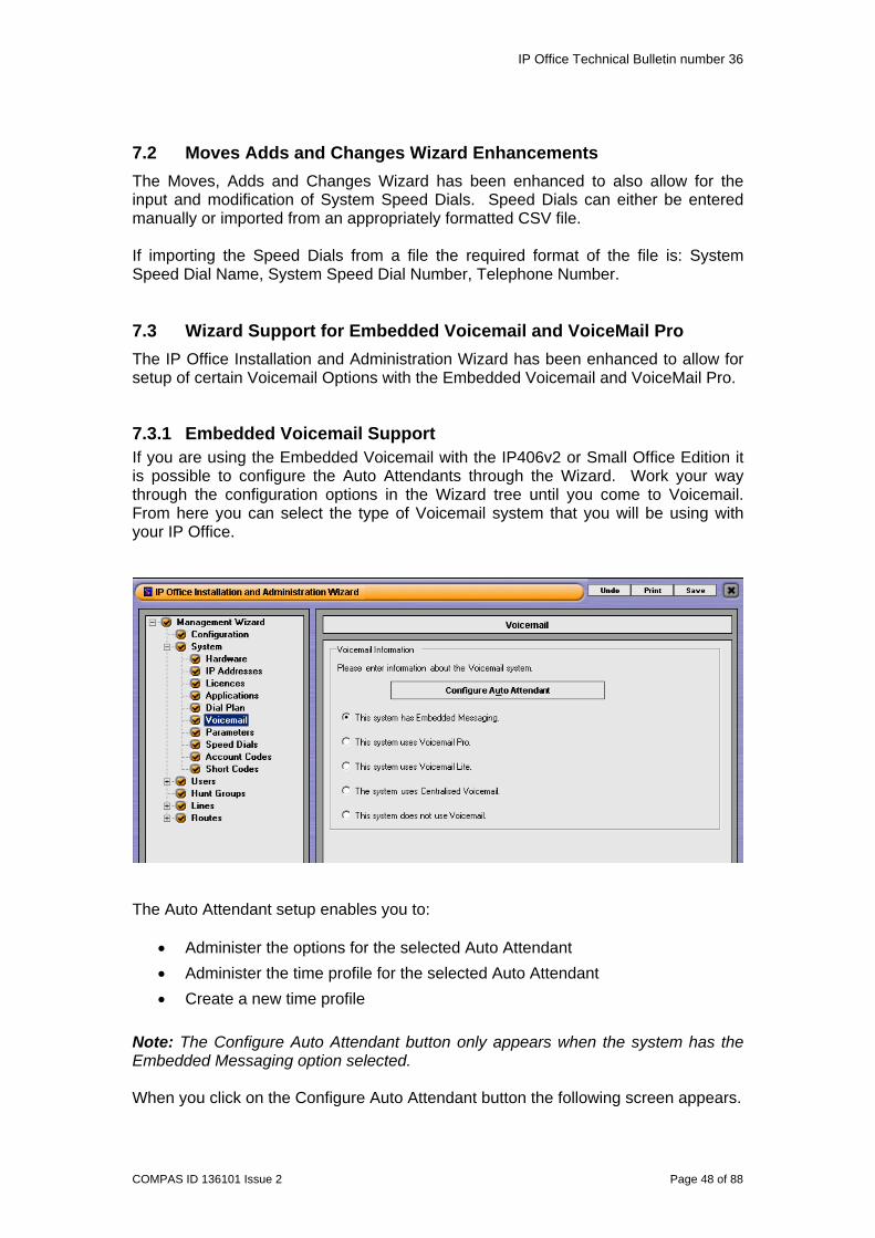
IP Office Technical Bulletin number 36
COMPAS ID 136101 Issue 2 Page 48 of 88
7.2 Moves Adds and Changes Wizard Enhancements The Moves, Adds and Changes Wizard has been enhanced to also allow for the input and modification of System Speed Dials. Speed Dials can either be entered manually or imported from an appropriately formatted CSV file. If importing the Speed Dials from a file the required format of the file is: System Speed Dial Name, System Speed Dial Number, Telephone Number. 7.3 Wizard Support for Embedded Voicemail and VoiceMail Pro The IP Office Installation and Administration Wizard has been enhanced to allow for setup of certain Voicemail Options with the Embedded Voicemail and VoiceMail Pro.
7.3.1 Embedded Voicemail Support If you are using the Embedded Voicemail with the IP406v2 or Small Office Edition it is possible to configure the Auto Attendants through the Wizard. Work your way through the configuration options in the Wizard tree until you come to Voicemail. From here you can select the type of Voicemail system that you will be using with your IP Office.
The Auto Attendant setup enables you to:
• Administer the options for the selected Auto Attendant • Administer the time profile for the selected Auto Attendant • Create a new time profile
Note: The Configure Auto Attendant button only appears when the system has the Embedded Messaging option selected. When you click on the Configure Auto Attendant button the following screen appears.

IP Office Technical Bulletin number 36
COMPAS ID 136101 Issue 2 Page 49 of 88
From here you can setup a maximum of four Auto Attendants, administer the button actions and setup the time profiles that the Auto Attendants will use. Note: You cannot setup the Auto Attendant timeout from within the Wizard. By default this will be set at 8 seconds. If you want to change this you will need to use Manager. Once you have setup the Auto Attendants that you want to use, proceed through the Wizard configuration until you come to setup the Incoming Routes.
Depending on the type of Lines you have and the service it has been configured for you may have to modify the existing Incoming Routes before you can setup the call routing to the Auto Attendants. If when you come to the Incoming Routes screen you have the routes shown above already setup you will need to delete them before you can setup the Auto Attendant routing.
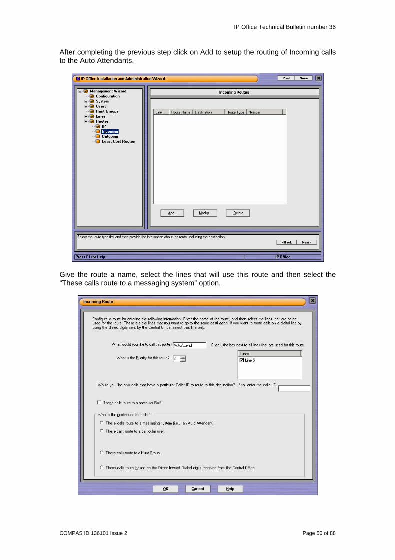
IP Office Technical Bulletin number 36
COMPAS ID 136101 Issue 2 Page 50 of 88
After completing the previous step click on Add to setup the routing of Incoming calls to the Auto Attendants.
Give the route a name, select the lines that will use this route and then select the “These calls route to a messaging system” option.

IP Office Technical Bulletin number 36
COMPAS ID 136101 Issue 2 Page 51 of 88
Once you select this option another configuration window will open.
This allows you to setup the incoming route to the Auto Attendant. If you are going to use the Auto Attendant timeout feature then you also need to select a destination to redirect the calls to. You can also click on modify at this screen if you want to check or modify what is setup for the selected Auto Attendant. When you have completed you setup click on OK.
Continue working through the configuration and then save the configuration and send it to your IP Office unit.
7.3.2 VoiceMail Pro Support With the introduction of IP Office 3.0 the Wizard can create simple VoiceMail Pro Auto Attendants. Note: When creating VoiceMail Pro Auto Attendants using the Wizard these cannot be edited through the VoiceMail Pro GUI, only through the Wizard.

IP Office Technical Bulletin number 36
COMPAS ID 136101 Issue 2 Page 52 of 88
Work your way through the configuration options in the Wizard tree, making sure that you add a VoiceMail Pro license, and continue until you come to Voicemail. From here you can select the type of Voicemail system that you will be using with your IP Office. Select “This system uses VoiceMail Pro” and enter the IP Address of the PC running VoiceMail Pro application.
If you leave the IP Address at its default setting, 255.255.255.255, then the “LoadVoiceMailData” option at the bottom of the screen will not be available. Clicking on this will allow you to select if you want to work online or offline.

IP Office Technical Bulletin number 36
COMPAS ID 136101 Issue 2 Page 53 of 88
When you are working with VoiceMail Pro, you can choose to work Online or Offline. If you select to work online the Wizard will read the Short Code Start Points from the VoiceMail Pro Server (using the VoiceMail Pro's IP Address). If you are not connected to the VoiceMail Pro server, you can create a new callflow (by choosing Offline and Create New), or you can read in a file that was previously created (Offline and Existing). When working online, there is also a local copy of all of the callflows at the displayed location. These options are independent of the configuration. You could be working offline for the switch and online with VoiceMail Pro. Once you have setup this information proceed through the Wizard configuration until you come to setup the Incoming Routes. As previously explained in the Embedded Voicemail section depending on the type of Lines you have and the service it has been configured for you may have to modify the existing Incoming Routes before you can setup the call routing to the Auto Attendants. Click on Add to setup the Incoming Route for the Auto Attendant.
Give the route a name, select the lines that will use this route and then select the “These calls route to a messaging system” option.

IP Office Technical Bulletin number 36
COMPAS ID 136101 Issue 2 Page 54 of 88
In the case where you are connected to VoiceMail Pro, the Short Code Start Points are listed in the Auto Attendant box. If you are not connected to Voicemail Pro, any short codes that are already created and associated with the feature “VoiceMailNode” will be displayed. Click on New to setup the Auto Attendant.
Two more options are presented to you here. You can select that only external callers can access the Auto Attendant and/or that callers can leave a message. Alternatively you can leave both of these options un-ticked. Once you have configured the options you require click on OK.

IP Office Technical Bulletin number 36
COMPAS ID 136101 Issue 2 Page 55 of 88
From the next screen add the Short Code that you will use to access this Auto Attendant and click on OK. Continue working through the Wizard configuration tree.
When setting up VoiceMail Pro Auto Attendants in the Wizard an additional menu item appears at the end of the configuration tree, “Voicemail”
From the Parameters screen you can set the following information:
• What Mode the system will run in: Intuity or IP Office Mode • Language Mode: Monolingual (one language) or Bilingual (two languages) for
prompts. • Prompts: When selecting Bilingual mode you can select the Primary and
Secondary language for the prompts. If this is not filled in callers will hear silence when VoiceMail Pro answers.
• Specify the extension VoiceMail Pro will call to record greetings.

IP Office Technical Bulletin number 36
COMPAS ID 136101 Issue 2 Page 56 of 88
When creating the Auto-Attendant callflows within VoiceMail Pro the option to set an extension number through which to record the messages is available. When a prompt is to be recorded the VoiceMail Pro will call the defined extension number. A user can then record the appropriate Auto-Attendant message. It is also possible to record the prompts via a PC. When configuring the Voicemail parameters you can select if one or two languages are to be supported. If two is selected recording of Auto-Attendant Messages will be prompted in the primary and secondary languages. If bilingual mode (2 languages are selected), the initial message needs to be recorded. This greeting will ask the users’ to choose what language they want to proceed in. This and all other greetings need to be recorded in both languages. When a call comes in, and this initial greeting has been played, the user may choose 1 or 2 for the primary or the secondary language. Once a language is selected, the VoiceMail Pro will play all the rest of the greetings in the selected language. VoiceMail Pro must be defined as the Voicemail option for access to the defined VoiceMail Pro configuration options within the Wizard. When you have configured these options click on Next.

IP Office Technical Bulletin number 36
COMPAS ID 136101 Issue 2 Page 57 of 88
You now need to setup the Time Profiles that will be used by the Auto Attendant.
The Wizard will allow you to define the day of the week each Auto-Attendant is active. The Day of the Week Options will be synchronized with the time profile defined for the Auto Attendant.

IP Office Technical Bulletin number 36
COMPAS ID 136101 Issue 2 Page 58 of 88
From this screen you setup what will happen dependant on the option the callers choose.
By clicking on each button in turn a separate window appears which allows you to define what happens when this button is pressed.
Select the action that is required and then go into settings to finish the programming of that option.
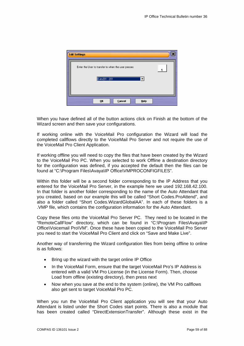
IP Office Technical Bulletin number 36
COMPAS ID 136101 Issue 2 Page 59 of 88
When you have defined all of the button actions click on Finish at the bottom of the Wizard screen and then save your configurations. If working online with the VoiceMail Pro configuration the Wizard will load the completed callflows directly to the VoiceMail Pro Server and not require the use of the VoiceMail Pro Client Application. If working offline you will need to copy the files that have been created by the Wizard to the VoiceMail Pro PC. When you selected to work Offline a destination directory for the configuration was defined, if you accepted the default then the files can be found at “C:\Program Files\Avaya\IP Office\VMPROCONFIGFILES”. Within this folder will be a second folder corresponding to the IP Address that you entered for the VoiceMail Pro Server, in the example here we used 192.168.42.100. In that folder is another folder corresponding to the name of the Auto Attendant that you created, based on our example this will be called “Short Codes.ProAttend”, and also a folder called “Short Codes.WizardGlobalAA”. In each of these folders is a .VMP file, which contains the configuration information for the Auto Attendant. Copy these files onto the VoiceMail Pro Server PC. They need to be located in the “RemoteCallFlow” directory, which can be found in “C:\Program Files\Avaya\IP Office\Voicemail Pro\VM”. Once these have been copied to the VoiceMail Pro Server you need to start the VoiceMail Pro Client and click on “Save and Make Live”. Another way of transferring the Wizard configuration files from being offline to online is as follows:
• Bring up the wizard with the target online IP Office • In the VoiceMail Form, ensure that the target VoiceMail Pro’s IP Address is
entered with a valid VM Pro License (in the License Form). Then, choose Load from offline (existing directory), then press next
• Now when you save at the end to the system (online), the VM Pro callflows also get sent to target VoiceMail Pro PC.
When you run the VoiceMail Pro Client application you will see that your Auto Attendant is listed under the Short Codes start points. There is also a module that has been created called “DirectExtensionTransfer”. Although these exist in the
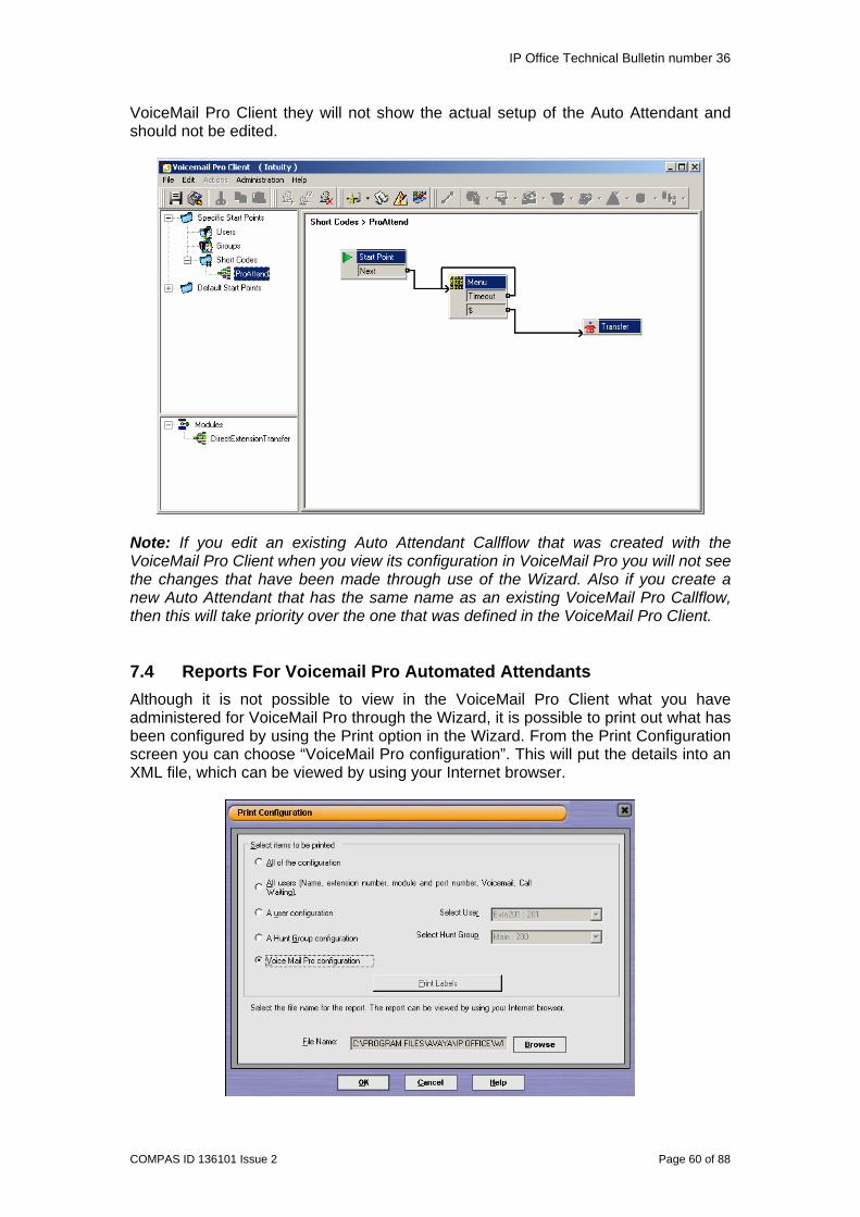
IP Office Technical Bulletin number 36
COMPAS ID 136101 Issue 2 Page 60 of 88
VoiceMail Pro Client they will not show the actual setup of the Auto Attendant and should not be edited.
Note: If you edit an existing Auto Attendant Callflow that was created with the VoiceMail Pro Client when you view its configuration in VoiceMail Pro you will not see the changes that have been made through use of the Wizard. Also if you create a new Auto Attendant that has the same name as an existing VoiceMail Pro Callflow, then this will take priority over the one that was defined in the VoiceMail Pro Client. 7.4 Reports For Voicemail Pro Automated Attendants Although it is not possible to view in the VoiceMail Pro Client what you have administered for VoiceMail Pro through the Wizard, it is possible to print out what has been configured by using the Print option in the Wizard. From the Print Configuration screen you can choose “VoiceMail Pro configuration”. This will put the details into an XML file, which can be viewed by using your Internet browser.
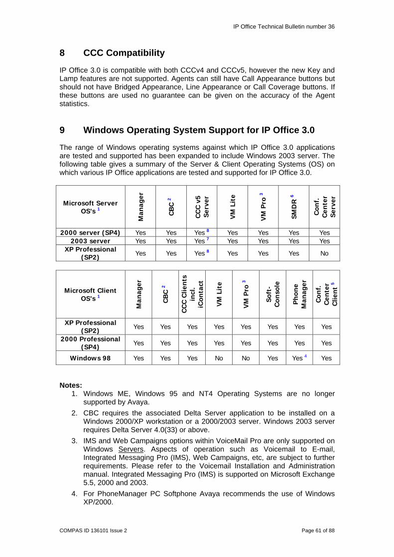
IP Office Technical Bulletin number 36
COMPAS ID 136101 Issue 2 Page 61 of 88
8 CCC Compatibility
IP Office 3.0 is compatible with both CCCv4 and CCCv5, however the new Key and Lamp features are not supported. Agents can still have Call Appearance buttons but should not have Bridged Appearance, Line Appearance or Call Coverage buttons. If these buttons are used no guarantee can be given on the accuracy of the Agent statistics. 9 Windows Operating System Support for IP Office 3.0
The range of Windows operating systems against which IP Office 3.0 applications are tested and supported has been expanded to include Windows 2003 server. The following table gives a summary of the Server & Client Operating Systems (OS) on which various IP Office applications are tested and supported for IP Office 3.0.
Microsoft Server OS's 1
Man
ager
CB
C 2
CC
C v
5 Se
rver
VM
Lit
e
VM
Pro
3
SMD
R 6
Con
f.
Cen
ter
Serv
er
2000 server (SP4) Yes Yes Yes 8 Yes Yes Yes Yes 2003 server Yes Yes Yes 7 Yes Yes Yes Yes
XP Professional (SP2) Yes Yes Yes 8 Yes Yes Yes No
Microsoft Client OS's 1
Man
ager
CB
C 2
CC
C C
lien
ts
incl
. iC
onta
ct
VM
Lit
e
VM
Pro
3
Soft
-C
onso
le
Ph
one
Man
ager
Con
f.
Cen
ter
Clie
nt
5
XP Professional (SP2) Yes Yes Yes Yes Yes Yes Yes Yes
2000 Professional (SP4) Yes Yes Yes Yes Yes Yes Yes Yes
Windows 98 Yes Yes Yes No No Yes Yes 4 Yes
Notes:
1. Windows ME, Windows 95 and NT4 Operating Systems are no longer supported by Avaya.
2. CBC requires the associated Delta Server application to be installed on a Windows 2000/XP workstation or a 2000/2003 server. Windows 2003 server requires Delta Server 4.0(33) or above.
3. IMS and Web Campaigns options within VoiceMail Pro are only supported on Windows Servers. Aspects of operation such as Voicemail to E-mail, Integrated Messaging Pro (IMS), Web Campaigns, etc, are subject to further requirements. Please refer to the Voicemail Installation and Administration manual. Integrated Messaging Pro (IMS) is supported on Microsoft Exchange 5.5, 2000 and 2003.
4. For PhoneManager PC Softphone Avaya recommends the use of Windows XP/2000.

IP Office Technical Bulletin number 36
COMPAS ID 136101 Issue 2 Page 62 of 88
5. Conferencing Center Web Client simply requires Internet Explorer 6.0 or higher (no other application required).
6. Although a server application, IP Office SMDR can also run on a Windows 98 SE, 2000, 2003, Windows NT4 and Windows XP client Operating Systems but should not run on the same PC as a CBC or CCC Delta Server.
7. Multimedia CCC operation on Windows 2003 server will require CCC v5 (planned May 05). Windows XP Professional, Windows 2000 Professional can be used but would typically support a maximum of 10 web clients. Microsoft Internet Information Service (IIS) installed capable of supporting as many web clients as required (please refer to Microsoft for licensing).
8. Use of Windows 2000/XP Professional workstation for CCC server is only recommended in small contact centers (<10 agents) that have low call volumes (300-500 calls per day).
10 Issues Resolved in IP Office 3.0 Software
All customer issues addressed in the current released versions of IP Office 2.1.27 software and associated applications are included in 3.0. As a reminder the issues addressed are listed below:
10.1 Core Software • 2420 Station log file no longer truncates the telephone number if a call is
transferred repeatedly. • LCR alternate route now works if force account code is enabled in user
restrictions. • The time profile end time is now more accurate. • Remote call forward now works when forced account code is enabled. • SNMP – spurious traps are no longer seen, warm and cold start traps are
now correctly generated. SysObjects ID’s are now correct. • Chinese E1R2 issues - the seize command now correctly sets '1' in the 'C' bit. • Fax calls from a PRI line to an E&M tie line now propagate reliably. • If a user is call listening to another extension, Voicemail cannot now intrude
upon this call. • Users are now able to transfer to account code restricted numbers from an
external call via VoiceMail Pro. • Internal Auto Attendant does not now disconnect caller if they dial digit ‘1’. • Call Connect messages over QSIG are now responded to correctly. • The status of users in groups is now reflected correctly in Manager. • Overflow groups now ring in the documented order. • Multiple simultaneous call intrusions upon a single analogue handset now all
intrude correctly. • Hold music will now run correctly on an internal memory card on the Small
Office Edition. • An external call forwarded off switch via a hunt group to a mobile or cell
number will now return to Voicemail correctly. • An external call answered and transferred to an internal extension will now
ring with the correct cadence. • LDAP is now working as designed. • A controlled reboot of an IP Office no longer results in ‘password error’ being
displayed on IP terminals.
IP Office Technical Bulletin number 36
COMPAS ID 136101 Issue 2 Page 63 of 88
• A large number of IP terminals, 100 plus, configured on a system no longer delays a controlled reboot from taking place.
• RoundTripDelay Request or Delay packets not reaching their destination cannot now cause a 4602 terminal to stop responding.
• An alias for a forwarding number for a user can now be modified. • IP Office 406 now supports paging to a group of more than 5 IP terminals.
In addition to the above fixes the following has also been addressed in 3.0 core software:
• When using the “Directory” feature on a 2420 the Left/Right scroll button and Exit button are now used to navigate through the list of names.
10.2 VoiceMail Pro
• The VoiceMail Pro Service does not stop when an IP Office reconnects to a running VoiceMail Pro, if user data changes have been made on the IP Office while the VoiceMail Pro was disconnected.
• Phone status changes no longer occur without user interaction. • When announcing queue prompts to queued callers, the start of the
announcement is now heard. • VoiceMail Pro whisper transfer action now works as documented. • Australian Voicemail messages are no longer over-trimmed by approximately
2 seconds. • The Assisted transfer action in VoiceMail Pro now works as documented.
10.3 IP Office Conferencing Center • None
10.4 User Applications 10.4.1 PhoneManager
• Calls that are cleared by the caller whilst queuing are no longer displayed as a ringing call in PhoneManager.
10.4.2 SoftConsole • End option on SoftConsole now only disconnects the consultation call, not the
caller as well.
10.4.3 TAPI • None
10.5 Wizards • None
10.6 DECT • An issue with the DECT Service appearing to stop has now been resolved. • With the DECT service running calls now forward on no answer correctly. • DECT Service no longer performs a ‘monitor all’ request for each user, thus
reducing network traffic. • CLI integration on DECT no longer fails after a period of time. • Blind transfers to DECT no longer cut off callers in certain circumstances.
IP Office Technical Bulletin number 36
COMPAS ID 136101 Issue 2 Page 64 of 88
11 Known Issues
The following is a list of issues that exist in this release of IP Office 3.0 software:
11.1 Core Software • When using ContactStore if you use a shortcode to specify that a certain CLI
number should be sent for outbound calls the call will not be sent to the Voice Recording Libraries. The recording is still made but will be placed into the users own mailbox.
• XM24 module does not allow buttons to be programmed as appearance buttons.
• Voicemail ringback answered via PhoneManager makes a single phantom call after the Voicemail message has been retrieved.
• Adding a new VOIP user is not mergeable, the system must be rebooted. • Calling ID shows partially when callers name over 10 characters. • Problem with IP Phone call disconnection after a conference call. When the
conference call ends the call is not automatically cleared from the IP Phone, the user must hang up to end the call.
• Call cannot be answered by Coverage Receiver if the call arrived at the Coverage Sender across a Small Community Network.
• VM Pro AA/VM transfer to Coverage Sender with DND active does not alert at Coverage Receiver.
• Unconditional forward to mobile does not initiate Voice Recording Library auto recording.
• Pickup of an external forwarded Hunt Group call drops the inbound trunk. • POT phone with outgoing restrictions receives silence when making an
outgoing call to a barred number. • When two systems are connected together via a T1 tie line administered as
T1 tie auto mode, if a call is placed on hold it gets disconnected. • Fixed VM button on 24xx/54xx does not work when off hook. • When using Least Cost Routing if the main route fails then the first call to be
made after the failure waits for the timeout and then clears down. Any further calls use the alternate route successfully.
• Forcing an agent that is in a Busy Not Available state to a Ready state forces the agent to a Busy Wrap Up state.
• 5410 voicemail passwords are listed in the phone call log if they are a hot desk user.
• Fax server routing from VoiceMail Pro only works with DTMFB, not DTMFF. • Cannot configure a National Prefix for ISDN line when in German locale. • When using the Admin feature to check the administration of a Coverage
button or Bridged Appearance button that does not have a lamp or does not have an indicator on the terminal, the button will not show as “Disabled” even though it is.
• For a T1 line if E&M-TIE is selected and the Outgoing Trunk Type is set to Automatic, no secondary dial tone is provided for outgoing calls on this line.
• An issue was identified in the field when using 4610/5610 with a Cajun P333T-PWR. If the Cajun has the wrong Powerline image version it is unable to drive the phones. The latest Powerline image version, 1.3.24, should be loaded.
11.2 Manager • In Manager preferences - Edit - Load Last File does not work.
IP Office Technical Bulletin number 36
COMPAS ID 136101 Issue 2 Page 65 of 88
11.3 VoiceMail Pro • When connecting to an IP Office with the ENG locale VoiceMail Pro does not
recognize this as a valid locale and displays an error sating that the locale has been changed to EN.
• When using IMS, Outlook 2003 running in Exchange Cached Mode is not supported.
• Italian Translation errors in VoiceMail Pro Client. • When running VoiceMail Pro in IP Office mode and the user does not have a
source number configured when they dial *17 to access Voicemail they do not hear the "Remote access is not configured on this mailbox" prompt.
• Queuing does not carry Whisper Action data. • VBScript action stops working after idle period. • No time played at start of messages for Chinese VoiceMail Pro. • Mixture of male and female prompts for Chinese VoiceMail Pro.
11.4 IP Office Conferencing Center • Cannot input more than 8 participants from Local Address Book at any one
time. • Conferencing Center not synchronizing presentations.
11.5 User Applications 11.5.1 PhoneManager
• Personal Distribution Lists do not work when Centralized VoiceMail is being used. The users at the site with VoiceMail can access the PDL setup through PhoneManager, those on the remote sites do not see a list of available mailboxes when using PhoneManager. It is still possible to setup Personal Distribution Lists via the phone for these users.
• When using Drag and Drop to create a conference call remote SCN users dragged into the call may experience one-way speech. If you put the call on hold and dial the user from the icons in PhoneManager or through the phone this issue is not experienced.
• When setting up Personal Distribution Lists if you add remote SCN users to the list when you then view the list there is a blank entry displayed where their name should be. This does not stop the PDL from working and any message forwarded to that PDL will be delivered to all members of the list.
• Cancelling a call before entering a PIN number does not clear the call correctly.
• When sending an Instant Message you must press enter key twice to send the message.
• PIN code error message box displayed before users are asked to enter the PIN.
• Phone Manager PC Softphone user - speed dial with correct PIN gives error message.
• When going into preferences and then clicking on OK to exit the screen toggles the agent status between Ready and Busy Wrap-Up.
• Personal Distribution List configuration does not allow maximum users to be entered.

IP Office Technical Bulletin number 36
COMPAS ID 136101 Issue 2 Page 66 of 88
• When creating a new Account code speed dial with PIN Dialling the OK button is not enabled.
• Translation errors when installing in Chinese.
11.5.2 SoftConsole • When you place a call on hold it is not possible to use the Hold Against
feature to hold the call against a busy extension. If you do not place the caller on hold first and select an entry from the directory window the Hold Against option will be available.
• Forwarding Users causes the User to go out of group.
11.5.3 TAPI • When installing the TAPI driver you may not be able to select this to make a
call from Microsoft Outlook. A fix for this has been provided on the User 3.0.12 CD. On the CD is a directory called “Patch” which contains a new version of the TAPI driver, the file is called tspi2w.tsp (version 1.0.0.25). To install this version you need to do the following:
1) Stop the Telephony service. If you have a problem stopping this
service it may be because the Remote Access Connection Manager service is running. If you have this problem you will need to disable that service and then reboot your PC before you are able to stop the Telephony service.
2) Copy the tspi2w.tsp file into the WINNT\System32 directory. 3) Restart the Telephony service. Also restart the Remote Access
Connection Manager service if you had to stop this. 4) Restart Outlook.
11.6 Wizards
• When using the Wizard if you apply a template to a user their Source Numbers will be removed. You will need to open the configuration in Manager to add these back in.
• When creating a default Auto Attendant by going to Incoming Routes and creating an Auto Attendant that only has the Direct Extension Transfer option, the prompt that is used is aa_01.wav ("Key in the extension number"), it should be a60.wav ("Key in the extension number followed by a pound sign).
• When programming buttons with the Adds, Moves and Changes Wizard in the drop down list of button functions, you get two Appearance buttons, one of these should be “Line Appearance”.
• When programming buttons with the Adds, Moves and Changes Wizard the “SetHuntGroupNightService” feature does not allow you to specify the group.
• Screen Layout issues in Korean Wizard. • Converting a PRI line to a T1 line may result in Line ID being set as 0.
11.7 DECT • None
IP Office Technical Bulletin number 36
COMPAS ID 136101 Issue 2 Page 67 of 88
12 Technical Notes
IMPORTANT INFORMATION – IP 403 UPGRADE ONLY An intermediate upgrade step is required when performing an upgrade of an IP403 from Release 2.1(29) or earlier to 3.0. The Base Unit only must first be loaded with 1.99(1003) if it is running pre 2.0 software, then 2.0 and then 2.99(1000). Systems already running 2.x just need to load 2.99(1000). Both of these versions are included on the Admin CD. From this version a full system upgrade should then be performed to Release 3.0.
An intermediate upgrade step is required when performing an upgrade of an IP403 from Release 2.1(29) or earlier to 3.0. The Base Unit only must first be loaded with 1.99(1003) if it is running pre 2.0 software and then 2.99(1000). Systems already running 2.x just need to load 2.99(1000). Both of these versions are included on the Admin CD. From this version a full system upgrade should then be performed to Release 3.0. Please note that the version of the binary for SO8 modules, nas0-16.bin, supplied as a part of this release is intentionally 5.0(35) and will operate correctly with the other binaries supplied in this release. Please follow the requisite guidelines for upgrading loaders on IP 403 systems. 12.1 Upgrade Installation Notes When upgrading from a version of software prior to 3.0 the following procedures must be observed and the instructions followed to achieve a successful upgrade. Note: It is recommended that any units not running a minimum of 2.0 software should be upgraded to this version first before upgrading to 3.0. If this process is not followed Avaya cannot guarantee that the configuration will be upgraded as intended. Before any upgrade commences the old Admin Suite must be removed and the 3.0 Admin Suite must be installed. The IP Office 3.0 Admin CD is fronted by the Microsoft installer, which behaves differently to the InstallShield package used on releases prior to 2.0. The following points should be noted:
• In all cases the old version of the Admin suite must be uninstalled using add/remove programs before the 3.0 Admin Suite is installed. The install will not occur unless the previous software has been removed. The same applies if moving between versions of the 3.0 Admin Suite.
• Microsoft .NET is required to support some of the applications. It is recommended that .NET is installed. This may take several minutes to complete. If you are already running the 2.1 admin suite .NET will already be installed.

IP Office Technical Bulletin number 36
COMPAS ID 136101 Issue 2 Page 68 of 88
• If installing on a PC with .NET Framework version 1.0 installed, this must be un-installed before installing 1.1. This can be done by going into Control Panel, selecting Add/Remove Programs and then selecting the 1.0 Microsoft .NET Framework.
Note: If performing a local upgrade (Validate check box not ticked) of the system software from a Windows 2000 PC directly connected to the IP Office, ensure that the IP address is set as static for the duration of the upgrade. When in client mode, Windows 2000 can lose its IP address settings immediately if it detects a disconnection from the LAN (this occurs as the unit reboots during the upgrade process). This can cause the upgrade to fail and the unit to be left with no software.
IMPORTANT INFORMATION – IP 403 UPGRADE ONLY When upgrading from any software version prior to 3.0 you must follow the instructions in section 12.3 to upgrade the software loader on the IP 403. A new loader was required when upgrading to 2.0 and another loader upgrade is now required to upgrade to 3.0. Failure to follow this procedure could leave your system inoperable.
12.2 IP406, IP406v2, IP412, and Small Office Edition Upgrade
Instructions To upgrade the Control and Expansion units do the following:
1 Ensure that you have received and made a backup copy of the latest IP Office configuration. If for any reason the upgrade fails the current configuration may be erased, so a backup copy is essential.
2 In Manager select File | Advanced | Upgrade. This will start the UpgradeWiz application.
3 After a few seconds the upgrade wizard should show the Control and Expansion units found.
4 A window similar to the following is displayed. The list shows the current software levels of the units and the level of the appropriate bin file that is available in the Manager/Binary working directories.

IP Office Technical Bulletin number 36
COMPAS ID 136101 Issue 2 Page 69 of 88
5 The current version and available versions are displayed. Tick the check box under Name if it is not already ticked then click on Upgrade.
6 Enter the password of the existing configuration (not the default). Click OK and IP Office will reboot and undergo the upgrade cycle. This takes around a minute to complete. Click OK to finish once the upgrade has completed. This will close the UpgradeWiz window.
7 If you tick the Validate check box the firmware is downloaded onto the IP Office and associated expansion modules but still leaves the system fully operational. Once it has been loaded a CRC check is performed to confirm the firmware transfer has not had any errors. When the Proceed with Upgrade box appears click on OK to continue. This then starts the upgrade process.
Note: It is only possible to perform step 8 if your IP Office system is already at 2.1. When upgrading from versions prior to 2.1 the Validate check box will be greyed out and a local upgrade, as detailed in the step 7, will be performed.
Note: When doing a remote upgrade on a IP406v2 the software may fail to be transferred correctly and the system could reset. If this happens, once the system has restarted attempt the remote upgrade again but only upgrade the CPU and then upgrade the expansion modules.
12.3 IP403 Upgrade Instructions There are three IP 403 binaries provided with this release: Two of these are for updating the loader, version 1.99(1003), version 2.99(1000) and the actual 3.0 binary, version 3.0(40). The loader upgrade must be done first and is required to create additional space in the area of Flash memory used for storing the operating software. These binaries exist in subdirectories of the main Manager directories. The loader versions can be found in the Manager\IP403V1_99 and Manager\IP403V2_99 directories, the actual 3.0 binary is in the Manager\IP403V3_0 directory. If your system is already running 2.0 or higher then you only need to do one loader upgrade (2.99). If your system is pre 2.0 then you must do two loader upgrades (1.99 and 2.99) before loading 3.0 software. When upgrading an IP 403, copy the required binary file into the Manager or Binary working directories. Failure to follow these instructions will result in a failure of the upgrade to your system. Note: Please read all of the following instructions before upgrading an IP 403. Upgrading the IP 403 from 1.x or 2.x requires an upgrade of the loader software to create additional space in the flash memory used for storing the operating software. The upgrade procedure for this is as follows:
1. Install the Admin Suite as normal. Do not open the Manager application.
Note: If your IP Office system is already running 2x software proceed to step 11
2. Using the Windows Explorer application on your PC open up the Program Files | Avaya | IP Office | Manager | IP403V1_99 folder. This will contain a file called ip403.bin. This file is level 1.99 of the IP Office 403 firmware and

IP Office Technical Bulletin number 36
COMPAS ID 136101 Issue 2 Page 70 of 88
contains the loader that is necessary to be able to upgrade from 1.x to 2.x, and must be used in place of the existing ip403.bin file. Copy this file to the Manager folder within the IP Office suite on your PC, that is, Program Files | Avaya | IP Office | Manager, to overwrite the existing ip403.bin file.
3. Open the Manager and ensure that you have received and made a backup copy of the latest IP Office configuration. If for any reason the upgrade fails, the current configuration may be erased, so a backup copy is essential.
4. In Manager select File | Advanced | Upgrade. This will start the UpgradeWiz application.
5. After a few seconds the upgrade wizard should show the Control and Expansion units found.
6. If no units are found using the broadcast address 255.255.255.255, this implies that the Manager PC is not on the same LAN as the IP Office. You should not continue in this case until you identify a Manager PC on the same LAN as the IP Office.
7. A window similar to the one below is displayed. The list shows the current software levels of the units and the level of the appropriate bin file that is available in the Manager/Binary working directories.
8. The current version and available versions are displayed. Tick the check box under Name if it is not already ticked then click on Upgrade.
9. Enter the password of the existing configuration (not the default). Click OK and IP Office will reboot and undergo the upgrade cycle. This takes around a minute to complete. Click OK to finish once the upgrade has completed. This will close the UpgradeWiz window.
10. When version 1.99 firmware is installed in the IP Office 403 system the front panel LEDs will flash a pattern, indicating that another version of the IP Office firmware must be loaded into the IP Office 403 base unit in order to make it fully functional. When version 1.99 firmware is installed, the functionality of the IP Office system is very much reduced - there is no trunk support, there is no telephone handset support, there is no support for VoIP functionality, etc. There is also no support for expansion units, so consequently these will not be visible in the upgrade wizard when the CPU is running version 1.99.
11. Once the 1.99 firmware has been installed 2.0 should then be loaded before progressing to the next step.
12. Using the Windows Explorer application on your PC open up the Program Files | Avaya | IP Office | Manager | IP403V2_99 folder. This will contain a file

IP Office Technical Bulletin number 36
COMPAS ID 136101 Issue 2 Page 71 of 88
called ip403.bin. This file is level 2.99 of the IP Office 403 firmware and contains the loader that is necessary to be able to upgrade from 2.x to 3.x, and must be used in place of the existing ip403.bin file. Copy this file to the Manager folder within the IP Office suite on your PC, that is, Program Files | Avaya | IP Office | Manager, to overwrite the existing ip403.bin file.
13. Repeat steps 4 – 9 of the above procedure.
Note: If your IP Office system is already at 2.1 software it is possible to load the 2.99 loader remotely as it does not impact the operational status of the system as the 1.99 loader does. Once the loader has been upgraded then the 3.0 software can also be upgraded remotely.
14. Now that the loader upgrades have been performed IP Office 3.0 can now be installed. Using the Windows Explorer application on your PC open up the Program Files | Avaya | IP Office | Manager | IP403V3_0 folder. This will contain a file called ip403.bin. This is the 3.0 IP Office firmware. Copy this file to the Manager folder within the IP Office suite on your PC, that is, Program Files | Avaya | IP Office | Manager, to overwrite the existing ip403.bin file.
15. Repeat steps 4 – 9 of the above procedure.
16. The IP Office 403 system will now be at version 3.0
17. Now that version 3.0 is on the CPU the expansion units can be upgraded in the normal way using the upgrade wizard.
Note: If you attempt to put 3.0 software directly onto an IP 403 system running 1.x or 2.x software without installing the new loaders first the upgrade will fail and the system will have to be recovered via the DTE maintenance port. Full details of this procedure can be found in the IP Office Job Aid “DTE Port Maintenance”.
• The above procedure need only ever be completed once.
• Once the above procedure has been completed all previous versions of IP Office 403 firmware may be freely loaded into the system.
• Inadvertently repeating the above procedure will do no harm. Version 1.99 and/or 2.99 firmware for the IP Office 403 system detects whether or not the loader needs upgrading automatically and will only ever perform the modification once.
• Confirmation of the activities outlined above may be obtained by connecting a PC serial port terminal to the DTE port on the back of the IP Office 403 and monitoring the session. An indication that the loader has been upgraded is provided.
• The AT-X4 command has been added to the new IP 403 loader to erase the extra configuration space now available. This should be used in conjunction with AT-X2 and AT-X3 when defaulting an IP 403 unit via the DTE port.
12.4 Unit Compatibility - Expansion Unit Interoperability All expansion units must be upgraded or downgraded to match the CPU software.

IP Office Technical Bulletin number 36
COMPAS ID 136101 Issue 2 Page 72 of 88
12.5 DS Phone Firmware Upgrades The Avaya 2410, 2420, 5410 and 5420 digital telephones in conjunction with IP Office 3.0 have the ability to upgrade their phone firmware. This allows customers to take advantage of new features and functionality without the need to replace the physical phone. The phones have a major and minor version of firmware. If a phones firmware is not at the correct version the IP Office will attempt to automatically upgrade the firmware to the correct version (major and minor). The new 5400 phones when shipped from the factory will have the correct version of firmware already installed, however any 2410 or 2420 phones in the field today may have an older version of firmware and will need upgrading. How to check your phones firmware version Checking the Firmware version on a 2410
1) At the bottom of the display there should be a button labelled “Option”. If this button is not visible press the menu button (the one that shows “Log” in the picture below) and this button will appear.
2) Press Option and the screen will now display some further options, one of
these is Self Test. Press that button and the display will change to show you details about the phone model and firmware loaded.
The firmware loaded into the phones has a major and minor version. The Major version in the example above is shown as “FWV=2” and the minor version is shown as “REL:2.00”. If the display does not match that shown above then the firmware needs to be upgraded. The majority of 2410 handsets tested during the field trial had “REL:1.01” firmware on them, not 2.00. This may be the case with any new 2410 handsets that you buy.

IP Office Technical Bulletin number 36
COMPAS ID 136101 Issue 2 Page 73 of 88
Checking the Firmware version on a 2420 The procedure for checking the firmware version on a 2420 is exactly as above, however the firmware that these phones need to be running is different.
The correct versions of firmware for use with IP Office Release 3.0 are:
FWV REL 2410 2 2.00 2420 4 4.00 5410 2 2.00 5420 4 4.00
When you upgrade your IP Office to 3.0 any existing 2420 phones that you have will probably need to be upgraded. To make this upgrade run as smoothly as possible please note the following information. The IP Office system uses TFTP to transfer the files to the phones so you need to make sure that the IP Office is setup correctly to do this.
In the System tab of the configuration there is an entry for TFTP Server IP Address. If this has been left blank then the IP Office will broadcast to find a TFTP server (the

IP Office Technical Bulletin number 36
COMPAS ID 136101 Issue 2 Page 74 of 88
Manager application) or if an IP address has been explicitly defined then this is the PC you need to have the Manager application running on. Once you have located the PC that will be used to make the TFTP firmware transfer then you need to make sure that you have copies of the relevant firmware files for the upgrade on that PC. These should already have been installed by the admin software and can be found in C:\Program Files\Avaya\IP Office\Manager. The files that are required are 2410_R2.bin and 2420_R4.bin. You should also have copies of 5410_R2.bin and 5420_R4.bin. If you do not have these files then they can be found on the 3.0 Admin CD in the \bin\2400 Firmware R4 directory. Note: The Manager application must be open on the relevant PC to enable the successful TFTP transfer of the firmware. Once the IP Office has been upgraded to 3.0 when the system reboots any 2400 phones that have the incorrect firmware on them will attempt to upgrade. The phone will display “Upgrading firmware, please wait”. This display will then change to “FIRMWARE UPDATE IN PROGRESS” and show current file size transferred and the elapsed time. The total time taken for the upgrade will be approximately 4-5 minutes per phone. Once the firmware update is complete the phone display will revert back to its normal display and the phone can be used again. To confirm the upgrade has been successful follow the instructions for checking the phone firmware version to confirm that the latest firmware has been loaded. When the upgrade process starts all phones on a module start to upgrade at the same time. If for any reason a phone fails to upgrade the upgrade process running on the expansion module must finish before you can attempt to re-upgrade a phone. If you attempt to re-upgrade a phone whilst the process is already running they will display “Upgrading firmware, please wait” and sit there displaying this until the upgrade process has finished and then they will start to re-upgrade. Once a phone has been upgraded it will not attempt to go through this process again. If for any reason a phone fails to upgrade there is a way you can force the IP Office to attempt a phone firmware upgrade again. As the IP Office only looks at the major version of firmware that a phone is running if any minor firmware versions are released then this procedure described below is also used to facilitate that upgrade. Installed with the Admin suite are some batch files that are used to set a flag in the IP Office so that a forced firmware upgrade will be carried out. A forced firmware upgrade will reload a version of firmware onto a phone regardless of the version it is already running. The batch files that are provided can be found in the Manager directory and are called: turn_on.bat, turn.off.bat, fw_on.bat and fw_off. You need to edit the two files called turn_on.bat and turn_off.bat. Right Mouse Click on each of these two files, and Select EDIT. This will open the file. Replace the <IP Address> string in the file with the IP Address of the IP Office, close and save the file. Example entry will look like the following: call fw_on 192.168.42.1

IP Office Technical Bulletin number 36
COMPAS ID 136101 Issue 2 Page 75 of 88
To set the flag you simply need to double click “turn_on.bat”. A pause has been added to this batch file to allow you to see whether or not the command has been executed successfully. You MUST receive a Transfer Successful message in the DOS window before continuing with any upgrades. Once the flag has been set there are three methods that can be used to upgrade the phones. If you are upgrading due to new firmware being available then options 2 and 3 are recommended. If you are upgrading due to a failure of a phone/phones to upgrade option 1 is recommended.
1) One at a time 2) A module at a time 3) All phones at once
One at a time: To upgrade the phones one at a time all you need to do is to unplug and re-plug the phone to start the upgrade process. The phone will display “Upgrading firmware, please wait”. This display will then change to “FIRMWARE UPDATE IN PROGRESS” and show current file size transferred and the elapsed time. The total time taken for the upgrade will be approximately 4-5 minutes. Once the firmware update is complete the phone display will revert back to its normal display and the phone can be used again. To confirm the upgrade has been successful follow the instructions for checking the phone firmware version to confirm that the latest firmware has been loaded. Using this method once a phone is in the process of upgrading its firmware no other phone on the same expansion module can be upgraded at the same time unless the upgrade starts within 10 seconds of the first one. If you attempt to upgrade another phone, or phones, on this same module outside of this 10 second window they will display “Upgrading firmware, please wait” and sit there displaying this until the first phone has finished its upgrade and then they will all upgrade in parallel. You can upgrade other phones on different expansion modules during this time, this limitation only applies to the same expansion module. A module at a time: A much better way of upgrading is to upgrade all phones on each expansion module at the same time. To enable this set the flag in the IP Office and then power cycle the expansion module. All of the phones will start the upgrade in parallel. If for any reason a phone or phones fail to start their upgrade process at the same time they will sit there displaying “Upgrading firmware, please wait“ until the other phones have finished upgrading and then they will upgrade. Other expansion modules can also be upgraded using this method by power cycling in turn, there are not the same limitations as there are in the single phone upgrade process. All phones at once: The quickest way to upgrade all of your phones is to have the upgrade process running on all phones at the same time. To do this you need to set the flag in the IP Office and then reboot the switch using the Manager application option File\Advanced\Reboot. If you do not follow this procedure to reboot the switch then the flag setting will not be saved when restarting. Once the IP Office reboots the phones will all start their upgrade procedure. Again as in the module at a time method there may be instances where phones do not start their upgrade at the same time so will wait until they can attempt the upgrade again.

IP Office Technical Bulletin number 36
COMPAS ID 136101 Issue 2 Page 76 of 88
Failure to upgrade: If for any reason a phone is unable to complete a successful upgrade the phone will not re-attempt this procedure until the flag in the IP Office is set to on again. When the phone first displays “Upgrading firmware, please wait” the flag for that extension is reset by the IP Office to off so needs to be turned on again by running the batch file again. The most likely cause of a failure is Manager not running. If this happens the phone will display “Waiting for TFTP” and then “2420_R4.bin: TFTPServerNotFound”. Although running the batch file will reset the flag for all extensions the other phones will not be upgraded unless you restart them during this time. Note: Once all of your phones have been upgraded successfully you must turn the flag off. This is achieved by using the turn-off.bat file. Failure to turn this off will result in your phone firmware being upgraded every time an IP Office reboot is necessary. 12.6 Phone Firmware Support The table below lists the phone firmware versions that are supported by IP Office 3.0 General Release software.
Phone Type Firmware Version 2402/ 5402 2.0 2410/ 5410 2.0 2420/ 5420 4.0
4606 1.83 4612 1.83 4624 1.83 5601 1.810 5602 1.806
5602sw 1.806 4601 1.82 4602 1.82
4602sw 1.82 4610sw/ 5610sw 2.1.3
4620 2.1.3 4620sw/ 5620sw 2.1.3
Note: It is not possible to upgrade the firmware on a 2402/5402
12.7 Upgrade Instructions for VoiceMail Pro How you upgrade to VoiceMail Pro 3.0 depends on the current version of VoiceMail Pro software that you are running. If you are running VoiceMail Pro 1.x you must first upgrade to VoiceMail Pro 2.1 before you upgrade to VoiceMail Pro 3.0. If you are already running 2.x VoiceMail Pro then you can go straight to VoiceMail Pro 3.0. When upgrading between versions of software upgrades are no longer supported so you must uninstall and reinstall to move between versions. This now also applies when moving between minor versions of software.

IP Office Technical Bulletin number 36
COMPAS ID 136101 Issue 2 Page 77 of 88
Upgrading from 1.x VoiceMail Pro to 2.1 VoiceMail Pro When upgrading from one software level to another the original software needs to be uninstalled. The uninstallation process only removes those files installed during the application’s original installation. Any other files added since are not removed, such as Voicemail messages. Any callflows that have been created will still operate, but they will not be editable after the upgrade. To make sure that the callflows can be edited they need to be exported before the upgrade process and then imported into the new software version. Note: After uninstalling any existing VoiceMail Pro server, always reboot the PC. Uninstalling does not remove any existing messages and greetings.
Backing-Up the VoiceMail Pro Database Before removing VoiceMail Pro, you must create a backup copy of the callflow database. This will contain any customizations made to the default callflow. Note: The Root.vmp file contains the compiled callflow (created using Save & Make Live). This type of file cannot be loaded back into the VoiceMail Pro Client for editing. The editable version of the callflow is stored in the file VMData.mdb.
1. Start the VoiceMail Pro Client.
2. From the File menu select the option Import or Export.
3. Select the option Export Callflows and click Next. 4. Enter a file path and file name ending in .mdb, e.g. C:\temp\backup.mdb.
Click Next.
5. Click Finish to start the export then click Close to complete the export procedure.
6. Close the program. Uninstall VoiceMail Pro
1. Open the Windows Control Panel.
2. Select Add/Remove Programs.
3. Select IP Office VoiceMail Pro and click Change/Remove.
4. From the options offered select Remove and click Next. 5. Follow any prompts given during the removal process.
6. When the process has been completed select the option “Yes, I want to restart my computer now” and click Finish.
VoiceMail Pro Installation
1. Insert the VoiceMail Pro CD. The Installation wizard should auto-start.
2. Select the language to be used during the installation. Click OK.
3. At the Welcome screen click Next.

IP Office Technical Bulletin number 36
COMPAS ID 136101 Issue 2 Page 78 of 88
4. At the customer information screen accept the defaults and click Next. 5. Select the type of installation required:
Note: On Windows NT/2000/XP, VoiceMail Pro Server is automatically installed as a service.
• Typical Install: Installs all the components of VoiceMail Pro including campaigns and the Campaign Web component.
• Compact Install: Installs all the components of VoiceMail Pro including campaigns.
• Custom Install: Allows selection of which components to install. The default selection before any changes is the same as the Typical selection.
6. At the Choose Destination Location screen accept the default locations, click
Next to continue.
7. Depending on the type of installation some or all of the following options will appear:
• If the Campaign Web Component is being installed, the web server type, location of the web server's HTML root, and the CGI bin directories will be prompted for.
• On Windows NT/2000/XP, if installing the VoiceMail Pro Server, the user account that the VoiceMail Pro service should use needs to be entered.
8. Unless there are specific reasons to do otherwise, accept the displayed program folder.
9. A summary of those items about to be installed is displayed. You can use Back to return to the previous screens and alter the selection if required. Click Next to begin the installation.
10. When the installation is complete select the option “Yes, I want to restart my computer now” and click Finish.
Restoring the VoiceMail Pro Database
1. Start the VoiceMail Pro Client.
2. From the File menu select the option Import or Export.
3. Select the option Import Callflows and click Next. 4. Use the Browse button to locate the backup file then click Next. 5. Click Finish to start the import then click Close to complete the import
procedure.
Note: After upgrading to VoiceMail Pro 2.x from 1.x the system will default to Intuity mode and Advice of Call Recording will be enabled. To change these options, start the VoiceMail Pro Client and change these settings from Administration | Preferences | General. Users of VoiceMail Pro running in IP Office mode will be asked to record their name when they first dial into VoiceMail Pro after the upgrade.
IP Office Technical Bulletin number 36
COMPAS ID 136101 Issue 2 Page 79 of 88
Upgrading from 2.x VoiceMail Pro to 3.0 VoiceMail Pro When upgrading between versions of software upgrades are no longer supported so you must uninstall and reinstall to move between versions. This now also applies when moving between minor versions of software. Backing Up the Existing VoiceMail Pro Database & Registry Before removing VoiceMail Pro, you should create a backup copy of the callflow database. This will contain any customizations made to the default callflow. You should also backup the registry settings specific to VoiceMail Pro.
1. Start the VoiceMail Pro GUI. 2. From the File menu, select the option Import or Export. 3. Select the option Export callflows and click Next. 4. Enter a file path and file name ending in .mdb, e.g. C:\temp\backup.mdb.
Click Next. 5. Click Finish to start the export then click Close to complete the export
procedure. 6. Close the program. 7. Insert the VoiceMail Pro CD for the new VoiceMail Pro and cancel the install
wizard that auto runs. 8. Right-click on the CD drive and select Open. 9. Locate the file Backupreg.bat and double-click it to run the application. This
backs up any registry settings associated with VoiceMail Pro. Note: Before proceeding to the next step make sure that the registry entries have been backed up correctly. The batch file should have created 3 backup files in the Windows Temp directory. Make sure that the following 3 files exists in that location:
• VMPro.arf
• NetAly.arf
• IMSGateway.arf
Uninstall VoiceMail Pro Open the Windows Control Panel.
1. Select Add/Remove Programs. 2. Select IP Office VoiceMail Pro and click Add/Remove. 3. From the options offered select Remove and click Next. 4. Follow any prompts given during the removal process.
When the process has been completed select the option Yes, I want to restart my computer now and click Finish. Restore the Registry
1. Right-click on the CD drive containing the VoiceMail Pro CD and select Open (reinsert the CD if necessary and cancel the install wizard).
IP Office Technical Bulletin number 36
COMPAS ID 136101 Issue 2 Page 80 of 88
2. Locate the file Restorereg.bat and double-click it to run the application. This restores the registry settings previously associated with VoiceMail Pro.
VoiceMail Pro Installation
1. Insert the VoiceMail Pro CD. The Installation wizard should auto-start.
2. Select the language to be used during the installation. Click OK.
3. At the Welcome screen click Next. 4. At the customer information screen accept the defaults and click Next. 5. Select the type of installation required:
• ACM Gateway: This mode is used to provide VoiceMail support for an Avaya
G.150 unit being used as a branch office gateway to ACM with Modular Messaging. Documentation for the installation and setup for such a system, including the VoiceMail aspects, is covered in separate Avaya G.150 documentation.
• Compact Install: This mode installs the minimum components for basic VoiceMail operation, that is the VoiceMail Pro server or service, the VoiceMail Pro Client application and the prompts appropriate to the selected installation language.
• Custom Install: This mode allows full selection of which components are installed. The only exception is the selection of VoiceMail Pro server or service, which will be overridden to match the Windows version. This mode is used for installation of IMS and Networked Messaging.
• Typical Install: This mode install the components for basic VoiceMail operation plus those required for web campaigns. It requires a suitable web server to be pre-installed on the VoiceMail Pro Server PC.
6. At the Choose Destination Location screen accept the default locations, click
Next to continue.
7. Depending on the type of installation some or all of the following options will appear:
• If the Campaign Web Component is being installed, the web server type, location of the web server's HTML root, and the CGI bin directories will be prompted for.
• On Windows NT/2000/XP, if installing the VoiceMail Pro Server, the user account that the VoiceMail Pro service should use needs to be entered.
8. Unless there are specific reasons to do otherwise, accept the displayed program folder.
9. A summary of those items about to be installed is displayed. You can use Back to return to the previous screens and alter the selection if required. Click Next to begin the installation.
10. When the installation is complete select the option “Yes, I want to restart my computer now” and click Finish.

IP Office Technical Bulletin number 36
COMPAS ID 136101 Issue 2 Page 81 of 88
Restore the VoiceMail Pro Database
1. Start the VoiceMail Pro Client.
2. From the File menu select the option Import or Export.
3. Select the option Import Callflows and click Next. 4. Use the Browse button to locate the backup file then click Next. 5. Click Finish to start the import then click Close to complete the import
procedure.
12.8 Upgrade Instructions Small Office Edition Embedded Voicemail The method of transferring and handling prompts has changed in IP Office 3.0. Prompts are no longer transferred from a Manager PC using TFTP following a system restart. For existing systems with Embedded Voicemail, the Voicemail will be inactive following the IP Office control unit being upgraded to 3.0. To reactivate the Embedded Voicemail the new 3.0 prompt set needs to be loaded onto the memory card. This action will only be required once. Prompt Source and Destination Location All the prompts for Embedded Voicemail can be found in the “LVMSound” folder on the IP Office 3.0 Admin CD. There are two sets, one for compressed memory cards in the G723 Files folder, and one for uncompressed memory cards in the G711 Files folder. Each set contains a folder for each supported language.
• IP Office Small Office Edition - Compressed Prompts The sub-folders in LVMSound/G723 Files should be copied to LVMAIL on the compressed memory card.
• IP Office 406 V2 - Uncompressed Prompts The sub-folders in LVMSound/G711 Files should be copied to LVMAIL on the uncompressed memory card.
The following sections cover two methods for copying the prompt folders to the required location. In both cases, following the copying the IP Office system should be restarted. During the restart the new prompt files are scanned and processed by the IP Office system. This can take up to 10 minutes before Embedded Voicemail restarts with the new prompts. This scanning process is much shorter on subsequent system restarts. Instructions are supplied for the Small Office Edition and the IP406v2 although Embedded Voicemail has not been supported on the IP406v2 in previous releases. It is included here for reference. Upgrading Prompts Using a Memory Card Reader This method uses a third-party memory card reader capable of reading and writing to a Type II Compact Flash memory card. It requires the IP Office to have already been upgraded to IP Office 3.0.
1. Remove the memory card from the IP Office control unit and if necessary from its PCMCIA carrier.

IP Office Technical Bulletin number 36
COMPAS ID 136101 Issue 2 Page 82 of 88
2. Following the memory card reader manufacturer's instructions, insert the memory card into the memory card reader.
3. Open the additional removable drive available on the PC. The folders should include a folder “LVMAIL”. Double-click the LVMAIL folder to open it.
• The existing files in this folder include user messages and greeting. DO NOT DELETE ANY EXISTING FILES. They also include pre-IP Office 3.0 Embedded Voicemail prompts which should be retained should it be necessary to downgrade the IP Office system.
4. Insert the IP Office 3.0 Administrator Application into the PC's CD drive. 5. When the installation wizard runs, select Cancel. 6. Using Explorer or My Computer, right-click the CD drive icon and select Open
to view files on the CD without running the installation wizard. 7. Open the folder LVMSOUND. 8. The next step depends on the IP Office control unit type:
• For an IP406 V2 control unit, double-click the G711 Files folder to open it.
• For a Small Office Edition control unit, double-click the G723 Files folder to open it.
9. There should be a folder for each language supported, e.g. ENG for UK English, ENU for US English and so on.
10. Drag and drop each of the language folders from the CD to the LVMAIL folder on the memory card.
• If a set of language folders already exists, you will be asked to confirm the action. Select “Yes To All” for replacing the folder and for the following file replacement query.
11. Following the transfer:
• Select all the language sub-folders in the LVMAIL folder. • Right-click and select Properties. • Under Attributes, click to remove any check mark set against Read
Only. • Click OK. If asked, select Apply to all Folders, sub-folders and files.
12. Again following the memory card reader manufacturer's instructions, remove the memory card from the memory card reader. With USB memory card readers, use the Windows Unplug or Eject Hardware wizard.
13. Reinsert the memory card into the IP Office control unit. 14. Restart the IP Office control unit by removing and then reapplying power. 15. Wait approximately 10 minutes following the restart for the IP Office to scan
the new prompts it has available. . 16. Test Embedded Voicemail operation by dialling *17 at an extension.

IP Office Technical Bulletin number 36
COMPAS ID 136101 Issue 2 Page 83 of 88
Upgrading Prompts Using TFTP File Transfer This method uses the IP Office Manager as a TFTP server to pass files from the CD drive to the memory card. It requires the IP Office to have already been upgraded to IP Office 3.0.
1. Using Manager, click on the folder icon (open) to receive the IP Office system's current configuration.
2. Select System from the configuration tree in the left-hand panel. 3. On the System tab of the form, set the following:
• Set the File Writer IP Address to the IP address of the PC running IP
Office Manager. • Set the TFTP Server IP Address to the IP Office's LAN1 IP address.
4. Save the configuration and send it back to the control unit. You will need to reboot the system for this change to take place.
5. Within Windows, select Start | Run. 6. Enter “cmd” and click OK to open a command line window. 7. Type the CD drive letter and press Enter, for example enter D: 8. Type “cd LVMSOUND” and press Enter. 9. The next step depends on the IP Office control unit type:
For an IP406v2 control unit:
• Type “cd G711 Files” and press Enter.

IP Office Technical Bulletin number 36
COMPAS ID 136101 Issue 2 Page 84 of 88
• Type “send711” followed by the IP Office's LAN1 IP address, for example “send711 192.168.42.1”
• The batch file will start transferring all the necessary folders and prompt files.
For a Small Office Edition control unit:
• Type “cd G723 Files” and press Enter.
• Type “send723” followed by the IP Office's LAN1 IP address, for example “send723 192.168.42.1”
• The batch file will start transferring all the necessary folders and prompt files.
10. The whole process of transferring the prompt files can take up to 30 minutes. 11. When all the files have been transferred, close the command window. 12. Restart the IP Office control unit by removing and then reapplying power. 13. Following the restart the IP Office will scan the new prompts it has available.
The time taken to do this depends on the number of locales being used by the systems’ users.
14. Test Embedded Voicemail operation by dialling *17 at an extension. 12.9 Upgrade Instructions for IP Office Conferencing Center Note: An upgrade of Conferencing Center is supported from version 2.0.6 without the loss of data stored in the database. An upgrade from a release prior to 2.0.6 will result in the database being erased. Conferencing Center 3.0 allows two installation options:
• A full install (both the Web Booking and Web Client Host applications on the same server PC)
• A split install (the Web Booking application installed on one server and Web Client Host application on another server PC)
With an upgrade to 3.0, you have the option to keep the full install of Conferencing Center on the one server PC or make the installation split. To upgrade and keep the full install on one server PC:
1. Open the Control Panel and from Add/Remove Programs select Conferencing Center and click Change/Remove, from the options offered select Remove and click Next.
2. Follow any prompts given during the removal process. This will remove the application GUI only and the database will be not be affected.
3. Insert the Conferencing Center 3.0 CD. 3. Double click the Conference_Center_Install folder. 4. Double click setup.exe. 5. The InstallShield Wizard window displays stating that it will install
Conferencing Center on your computer. Click Next to continue. 6. The following install options are presented:

IP Office Technical Bulletin number 36
COMPAS ID 136101 Issue 2 Page 85 of 88
• Full Install: Installs all Conferencing Center components onto this server. Not recommended unless secure access to this server is put in place.
• Web Booking: Installs only the web booking component onto this server.
• Web Client Host: Installs only the web client component onto this server.
Select the Full Install option. Click Next. 7. In the Choose Destination Location window, a default destination folder for
installing Conferencing Center is presented. If this folder destination is sufficient, click Next.
• If you want to install in another folder destination, click Browse and navigate to the appropriate folder. Within the pop up dialog box, click OK within the Installshield Wizard window. Click Next.
8. Confirm that all installation settings presented in the Start Copying Files window is accurate and click Next to start copying the program files.
• If any of the information presented needs to be updated, click Back and make the necessary changes.
9. Select whether you want to restart the PC now or at a later time. We recommend restarting your PC now. Click Finish.
If you want to split the installation it is advisable to keep the existing Conferencing Center server PC as the Web Booking server and install the Web Client Host onto another server PC. To split the Web Booking and Web Client Host onto two server PCs with this software upgrade, do the following: Upgrade the existing server PC with ONLY the new Conferencing Center Web Booking application:
1. Open the Control Panel and from Add/Remove Programs select Conferencing Center and click Change/Remove, from the options offered select Remove and click Next.
2. Follow any prompts given during the removal process. This will remove the application GUI only and the database will be not be affected
3. Insert the Conferencing Center 3.0 CD.
4. Double click the Conference_Center_Install folder. 5. Double click setup.exe. 6. The InstallShield Wizard window displays stating that it will install
Conferencing Center on your computer. Click Next to continue. 7. The following install options are presented:
• Full Install: Installs all Conferencing Center components onto this server. Not recommended unless secure access to this server is put in place.
• Web Booking: Installs only the web booking component onto this server.

IP Office Technical Bulletin number 36
COMPAS ID 136101 Issue 2 Page 86 of 88
• Web Client Host: Installs only the web client component onto this server.
Select the Web Booking option. Click Next. 8. In the Choose Destination Location window, a default destination folder for
installing Conferencing Center is presented. If this folder destination is sufficient, click Next.
• If you want to install in another folder destination, click Browse and navigate to the appropriate folder. Within the pop up dialog box, click OK within the Installshield Wizard window. Click Next.
9. Confirm that all installation settings presented in the Start Copying Files window is accurate and click Next to start copying the program files.
• If any of the information presented needs to be updated, click Back and make the necessary changes.
10. Select whether you want to restart the PC now or at a later time. We
recommend restarting your PC now. Click Finish.
Install the Web Client Host on a second server PC by following these instructions.
Remember to redirect users to the new Web Client Host's URL by logging onto the Conferencing Center Scheduler as an administrator, accessing the Configuration window and entering the new URL into the URL for Web Client field.
Do the following to install ONLY the Web Client application onto the server PC:
1. Insert Conferencing Center CD. 2. Double click the Conference_Center_Install folder. 3. Double click setup.exe. 4. The InstallShield Wizard window informs you that Conferencing Center will be
installed onto the server PC. Click Next to continue. 5. The following install options are presented:
• Full Install: Installs all Conferencing Center components onto this server. Not recommended unless secure access to this server is put in place.
• Web Booking: Installs only the web booking component onto this server.
• Web Client Host: Installs only the web client component onto this server.
Select Web Client Host. Click Next. 6. Enter the IP Address of the server PC in which you have installed or will
install the Web Booking application. Click Next. 7. In the Choose Destination Location window, a default destination folder for
installing the Web Client application is presented. If this folder destination is sufficient, click Next.
• If you want the to install in another folder destination, click Browse and navigate to the appropriate folder. Within the pop up dialog box, click OK within the Installshield Wizard window. Click Next.

IP Office Technical Bulletin number 36
COMPAS ID 136101 Issue 2 Page 87 of 88
8. Confirm that all installation settings presented in the Start Copying Files window is accurate and click Next to start copying the program files.
• If any of the information presented needs to be updated, click Back and make the necessary changes.
9. Click Finish. 10. Restart the PC.
12.10 Upgrade Instructions for IP Office User Applications When upgrading from one software level to another the original software needs to be uninstalled first. The un-installation process only removes those files installed during the application’s original installation. Any other files added since are not removed. The settings for PBX configuration, Speed Dials, Calls In/Out/Missed tabs etc, are currently stored in the registry and will also remain. If your existing user applications are version 1.x software then you need to upgrade to 2.1 first. This is because the new Profiles used by PhoneManager use the existing registry entries for PhoneManager to build the profile xml file. These registry entries changed between version 1.x and 2.x so if you miss this step you will lose your PhoneManager configuration and speed dials. Upgrading from 1.x to 2.x uses the same process described below for upgrading to 3.0. To upgrade to any of the 3.0 User applications do the following: Uninstall User Applications
1. Open the Windows Control Panel.
2. Select Add/Remove Programs.
3. Select IP Office User Suite and click Change/Remove.
4. From the options offered select Remove and click Next. 5. Follow any prompts given during the removal process.
Upgrade Installation
1. Insert the User CD. The installation wizard should auto-start.
2. At the Welcome screen click Next. 3. If there are multiple IP Office units detected on your network select your unit
and then click on OK.
4. At the next screen select the User name from the list that this installation is associated with.
5. Click on Next and then Finish.
6. At the InstallShield Wizard welcome screen click on Next. 7. At the Choose Destination Location screen accept the default locations, or
choose a different installation directory, click Next to continue.
IP Office Technical Bulletin number 36
COMPAS ID 136101 Issue 2 Page 88 of 88
8. At the Select Components screen select the applications you want to install and click Next to continue.
9. If you are using PhoneManager in Agent Mode enter the Agent number at the next screen, or leave this blank and click Next.
10. Click Next to accept the Program Folder.
11. When the installation is complete click on Finish.
13 Assistance
13.1 Documentation & Software Documentation and Software can be found on www.avaya.com/support
1. Go to www.avaya.com/support 2. Select FIND DOCUMENTATION and DOWNLOADS by PRODUCT NAME 3. Select IP Office 4. Select the Software release required 5. Select the Documentation Categories required
Software can also be ordered on CD if required.
Description of new CD Media Material Code IP Office 3.0 User / Admin CD set 700345879 VoiceMail Pro 3.0 CD 700350457 CCCv5 CD 700330962 Engineers Toolkit CD 700345887 Conferencing Center 3.0 CD 700293913
13.2 IP Office Technical Training Avaya University training courses have been updated to reflect the new features offered with the IP Office 3.0 release. Details of the courses and their availability can be found at the Avaya Learning Centre:
http://www.avaya-learning.com Issued by: Avaya SMBS New Product Introduction Tel: +44 (0) 1707 392200 Fax: +44 (0) 1707 376933 Email: [email protected] Website: http://www.avaya.com/businesspartner