ip kvm-ic2300 ipkvm with ipmi - lanner · 4. when the booting process finishes, you could access...
TRANSCRIPT

IP KVM-IC2300 IPKVM with IPMI Quick Installation Guide / User Manual
Issue 1 June 2012

Version 1.0
Revision History
This document contains proprietary information of Lanner Electronics Inc. –and is not to be disclosed or used except in accordance with applicable agreements.
Copyright © 2012. All Rights Reserved.
Copyright© 2012 Lanner Electronics Inc. All rights reserved. The information in this document is proprietary and confidential to Lanner Electronics Inc. No part of this document may be reproduced in any form or by any means or used to make any derivative work (such as translation, transformation, or adaptation) without the express written consent of Lanner Electronics Inc. Lanner Electronics Inc. reserves the right to revise this document and to make changes in content from time to time without obligation on the part of Lanner Electronics Inc. to provide notification of such revision or change.
The information in this document is furnished for informational use only, is subject to change without notice, and should not be construed as a commitment by Lanner Electronics Inc. Lanner Electronics Inc. assumes no responsibility or liability for any errors or inaccuracies that may appear in this document or any software that may be provided in association with this document.
Rev Date Changes
1.0.1 June 19, 2012 Initial version

Version 1.0
TTaabbllee ooff CCoonntteennttss
AABBOOUUTT TTHHIISS PPRROODDUUCCTT............................................................................................................................................................................................................................................................ 33 PURPOSE................................................................................................................................................................................3 INTENDED AUDIENCE .............................................................................................................................................................3 HOW TO USE THIS DOCUMENT................................................................................................................................................3 SAFETY INFORMATION ...........................................................................................................................................................3 CONVENTIONS USED ..............................................................................................................................................................4
CCHHAAPPTTEERR 11 .................................................................................................................................................................................................................................................................................................... 55 IINNTTRROODDUUCCTTIIOONN...................................................................................................................................................................................................................................................................................... 55 11.. AABBOOUUTT TTHHEE IIPP KKVVMM--IICC22330000 .............................................................................................................................................................................................................................. 55 22.. FFEEAATTUURREESS ...................................................................................................................................................................................................................................................................................... 55 33.. SSAAFFEETTYY GGUUIIDDEELLIINNEESS .................................................................................................................................................................................................................................................. 77 44.. HHAARRDDWWAARREE IINNSSTTAALLLLAATTIIOONN ............................................................................................................................................................................................................................ 88 55.. CCOONNNNEECCTTIINNGG IIPPMMII VVIIAA CCOONNSSOOLLEE PPOORRTT .................................................................................................................................................................................. 88 66.. DDEEFFAAUULLTT VVAALLUUEESS.............................................................................................................................................................................................................................................................. 99 CCHHAAPPTTEERR 22 ................................................................................................................................................................................................................................................................................................ 1100 WWEEBB CCOONNFFIIGGUURRAATTIIOONN IINNTTEERRFFAACCEE................................................................................................................................................................................................................ 1100 11.. OOVVEERRVVIIEEWW.................................................................................................................................................................................................................................................................................. 1100 22.. PPRREEPPAARRAATTIIOONN...................................................................................................................................................................................................................................................................... 1100
LOGIN..................................................................................................................................................................................11 33.. DDAASSHHBBOOAARRDD.......................................................................................................................................................................................................................................................................... 1122
3.1 DASHBOARD INFORMATION...................................................................................................................................12 44.. SSEERRVVEERR HHEEAALLTTHH GGRROOUUPP ................................................................................................................................................................................................................................ 1144
4.1 SENSOR READINGS................................................................................................................................................14 4.2 EVENT LOG ...........................................................................................................................................................16
55.. CCOONNFFIIGGUURRAATTIIOONN ............................................................................................................................................................................................................................................................ 1177 5.1 DNS......................................................................................................................................................................17 5.2 MOUSE MODE .......................................................................................................................................................18 5.3 NETWORK .............................................................................................................................................................18 5.4 NETWORK LINK.....................................................................................................................................................21 5.5 NTP ......................................................................................................................................................................22 5.6 PEF MANAGEMENT...............................................................................................................................................23
5.6.1 Event Filter Tab ...............................................................................................................................................23 5.6.2 Alert Policy Tab ...............................................................................................................................................26 5.6.3 LAN Destination ..............................................................................................................................................29
5.7 SERVICES...............................................................................................................................................................31 5.8 SMTP SETTINGS ...................................................................................................................................................32 5.9 SSL .......................................................................................................................................................................34
5.9.1 Upload SSL ......................................................................................................................................................35 5.9.2 Generate SSL ...................................................................................................................................................36 5.9.3 View SSL ..........................................................................................................................................................37 5.9.4 Users................................................................................................................................................................39
66.. RREEMMOOTTEE CCOONNTTRROOLL .................................................................................................................................................................................................................................................... 4422 6.1 CONSOLE REDIRECTION ........................................................................................................................................42 6.2 JAVA CONSOLE.......................................................................................................................................................44

Version 1.0
77.. MMAAIINNTTEENNAANNCCEE.................................................................................................................................................................................................................................................................... 4466 7.1 FIRMWARE UPDATE ...............................................................................................................................................46 7.2 RESTORE FACTORY DEFAULTS...............................................................................................................................47 7.3 PRESERVE CONFIGURATION...................................................................................................................................48
88.. JJVVIIEEWWEERR ........................................................................................................................................................................................................................................................................................ 4499 8.1 VIDEO ...................................................................................................................................................................49 8.2 KEYBOARD............................................................................................................................................................50 8.3 MOUSE ..................................................................................................................................................................50 8.4 OPTIONS................................................................................................................................................................50 8.5 MEDIA...................................................................................................................................................................51 8.6 KEYBOARD LAYOUT..............................................................................................................................................53
8.6.1 Video Record ...................................................................................................................................................53

B-FOCUS 442 GW User Manual
3
About this product
Purpose The purpose of this document is to connection and management information for IP KVM-IC2300 through IPMI service.
Intended audience This document is for individuals who configure and manage IP KVM-IC2300.
How to use this document Use this guide to install or configure the IPMI service on the server system.
Safety information
WARNING: The following information lists the safety reminders for installation and maintenance personnel.
Read all instructions before attempting to unpack, install, operate, or connect power to this product. Please remember the following when you unpack and install this equipment:
Keep the chassis area clear and dust-free during and after the installation. Do not wear loose clothing or jewelry that could get caught in the chassis.
Fasten your tie or scarf and roll up your sleeves. Wear safety glasses if you are working under any conditions that might be hazardous to your eyes. Do not perform any action that creates a potential hazard to people or makes
the equipment unsafe.
Disconnect all power by turning off the power and unplugging the power cord before installing or removing a chassis or working near power supplies
Do not work alone if potentially hazardous conditions exist. Never assume that power is disconnected from a circuit; always check the circuit.
Operating Safety
Electrical equipment generates heat. Ambient air temperature may not be adequate to cool equipment to acceptable operating temperatures without adequate circulation. Be sure that the room in which you choose to operate your system has adequate air circulation.
Ensure that the chassis cover is secure. The chassis design allows cooling air to circulate effectively. An open chassis permits air leaks, which may interrupt and redirect the flow of cooling air from internal components.
Electrostatic discharge (ESD) can damage equipment and impair electrical circuitry. ESD damage occurs when electronic components are improperly handled and can result in complete or
intermittent failures. Be sure to follow ESD –prevention procedures when removing and replacing components to avoid these problems.
Wear an ESD-preventive wrist strap, ensuring that it makes good skin contact. If no wrist strap is available, ground yourself by touching the metal part of the chassis. Periodically check the resistance value of the antistatic strap, which should be between 1 and 10 megohms
(Mohms). EMC Notice This equipment has been tested and found to comply with the limits for a Class A digital device, pursuant to Part 15 of the FCC Rules. These limits are designed to provide reasonable protection against harmful interference when the equipment is operated in a commercial environment. This equipment generates, uses, and can radiate radio frequency energy and, if not installed and used in accordance with the instruction manual, may cause harmful interference to radio communications. Operation of this equipment in a residential area is likely to cause harmful interference in which case users will be required to correct the interference at their own expense.

Version 1.0
4
Class A Notice for FCC
Modifying the equipment without the authorization of Lanner Electronics, Inc. may result in the equipment no longer complying with FCC requirements for Class A digital devices. In that event, your right to use the equipment may be limited by FCC regulations, and you may be required to correct any interference to radio or television communications at your own expense.
This equipment is in compliance with the essential requirements and other relevant provisions of Directive 1999/5/EC.
Conventions used Following are all the special characters and typographical conventions used in this manual:
Convention Meaning Press Enter Means press the Enter or Return key or its equivalent on your
computer.
Note Introduces important additional information.
Caution Warns that a failure to follow the recommended procedure could result in loss of data or damage to equipment.
Warning Warns that a failure to take appropriate safety precautions could result in physical injury.
Warning Warns of danger of electric shock.

Version 1.0
5
Chapter 1 Introduction
1. About the IP KVM-IC2300
The IP KVM-IC2300 contains a powerful software stack combining the functionality of a Service Processor and of a Baseboard Management Controller (BMC). The software implements IPMI 2.0 and KVM/IP based on the service processor. It performs all the BMC management tasks defined by IPMI 2.0, which acts as a service processor, allows for video redirection and remote monitoring using KVM over LAN. For remote access, it runs an embedded web-server to provide a web management interface. It also runs a remote desktop service for direct access to the system’s desktop. The following section provides a list of software capabilities.
2. Features
IPMI Message Interface Support
• KCS (System Interface Support)
• IPMB
• LAN
• USB
Media Redirection
• Simultaneous floppy, Hard disk or USB and CD or DVD redirection.
• Efficient USB 2.0 based CD/DVD redirection with a typical speed of 20XCD.
• Support for USB key
• Completely secured (Authenticated or Encrypted) remote KVM or vMedia.
IPMI 2.0 based management
• BMC stack with a full IPMI 2.0 implementation
• Customizable sensor management
Event Log and Alerting
• Read Log events
• Sensor readings

Version 1.0
6
• SNMP traps
• E-Mail alerts
Sophisticated User Management
• IPMI based user management
• Added security with SSL (HTTPS)
• Multiple user permission level
• Multiple user profiles
Remote Server Power Control
• Server’s power status report
• Support for remotely power-cycle, power-down, power-up and server reset
Web based configuration
• Full configuration using web UI
• Fail-safe firmware upgrade
• Multi-language support in Web interface with English as the currently supported language

Version 1.0
7
3. Safety Guidelines
In order to reduce the risk of fire, electric shock and injury, please adhere to the following safety guidelines.
Carefully follow the instructions in this manual; also follow all instruction labels on this device. Only use the power adapter supplied with the device. Do not spill liquid of any kind on this device. Do not place the unit on an unstable stand or table; the unit may drop and become damaged. Do not expose this unit to direct sunlight. Do not place any hot devices close to this unit, as it may degrade or cause damage to it. Do not place any heavy objects on top of this unit. Do not use liquid cleaners or aerosol cleaners. Use a soft dry cloth for cleaning.

Version 1.0
8
4. Hardware Installation
1. Plug the AC adapter into an AC power socket, and connect its jack to the system’s power socket. If the system is not powered on, you will need to startup the IPMI service first. 2. To start the IPMI service separately without powering on the system, connect the console cable to the system’s console port. 3. Start the IPMI service as described in the following section. 4. When the booting process finishes, you could access the IPMI web interface through the IPMI port. 5. Open the browser and type in the default login username and password.
5. Connecting IPMI via Console Port
In case when you want to start the IPMI service alone without powering on the system, you can use the console port. The console port’s configuration is as follows:
Baud rate: 38400
Data bit: 8
Parity: none
Stop bit: 1
Flow control: hardware
Username: sysadmin
Password: superuser
When the console port is connected, the terminal will display the message to ask you to press the ESC key within 5 seconds to bypass the system startup and enter the IPMI U-Boot Command Line Interface. You should do so accordingly if you want to start the IPMI service manually before the console being redirected to be used for the overall system .
After entering the U-Boot menu, type bootfmh to start up the IPMI service. You may also config the Ethernet information of the LAN port for IPMI service with the ifconfig command. The original Ethernet configuration is as follows: eth0 Link encap:Ethernet HWaddr 00:90:0B:22:06:9A
inet addr:192.168.0.100 Bcast:192.168.0.255 Mask:255.255.255.0
inet6 addr: fe80::290:bff:fe22:69a/64 Scope:Link
UP BROADCAST RUNNING MULTICAST MTU:1500 Metric:1
RX packets:266206 errors:0 dropped:0 overruns:0 frame:0
TX packets:505833 errors:0 dropped:0 overruns:0 carrier:0
collisions:0 txqueuelen:1000
RX bytes:19256366 (18.3 MiB) TX bytes:123158055 (117.4 MiB)
Interrupt:2

Version 1.0
9
6. Default Values
The device is pre-configured with the following parameters. You may change the default values using the web interface. Refer to 5.9.4Users.
Web Management Interface User Name:admin Password: [admin] Local port address: 192.168.0.100
Subnet mask: 255.255.255.0
Console Connection
User Name: sysadmin
Password: superuser

Version 1.0
10
Chapter 2 Web Configuration Interface
1. Overview
The Web Management Interface is provided to let the configuration of the IPMI service as easily as possible. It provides a user-friendly graphical interface through a Web platform. In the next chapter, each configuration item is described in detail. Here we list the supported Internet browsers through which you can use to access these functions.
Operating System Browser Version Linux Windows MAC OS
Firefox 2.0 and above Yes: Default Yes No Internet Explorer 7 and above No Yes: Default No Safari 3.0 and above No Yes Yes: Default Chrome 2.0 and above No Yes No Opera 9.64 and above No Yes No
2. Preparation
Step 1: Please refer to the hardware installation procedure in Chapter 1 to prepare the device for IPMI management.
Step 2: You should configure your PC to the same IP subnet as the IPMI interface. Example: IPMI Interface: 192.168.0.100
Your PC: 192.168.0.x Step 3: Connect your PC to the IPMI port directly or to any network device such as a switch which also
connects to the IPMI interface. Make sure that the PING function is working properly. Step 4: Launch the Web browser (IE or Netscape) and enter the default IP address 192.168.0.100 into the
address bar to access the Web management page. Step 5: The Login dialog box will appear first.

Version 1.0
11
Login The Enter Network password window will appear when starting the configuration. Type admin for the User name and admin for the Password, then click the Login button.
Note: The username and password are case-sensitive.

Version 1.0
12
3. Dashboard
3.1 Dashboard Information
The Dashboard shows the hardware monitor information.
It monitors several critical parameters in PC hardware, including power supply voltages, fan speeds for both CPU and system fans, temperatures, and CPU voltage, etc.
Device Information The Device Information displays the following information:
Firmware Revision: The revision number of the firmware.
Firmware Build Time: This field shows the date and time on which the firmware is built.
Network Information The Network Information of the device with the following fields is shown here. To edit the network Information, click Edit.
MAC Address: Read only field showing the IP address of the device. V4 Network Mode: The IPv4 network mode of the device which could be disable, static or DHCP.
IPv4 Address: The IPv4 address of the device (could be static or DHCP). V6 Network Mode: The v6 network configuration of the device which could be disable, static or DHCP. IPv6 Address: The IPv6 address of the device.

Version 1.0
13
Remote Control To redirect the host remotely, launch Java Console from this section.
Click Launch to launch the console redirection and to manage the remote server. It will start downloading the jviewer.jnlp file which after downloaded and launched will open the Java redirection window.
Sensor Monitoring It lists all the available sensors on the device with the following informations.
• Status: The status column displays the state of the device. There are three states for status.
- Denotes normal state
-Denotes Warning State
- Denotes Critical State
If you click the icon, the sensor reading for that particular sensor will be displayed. For more information on sensor readings, see next section on Server Health.
X
!

Version 1.0
14
4. Server Health Group
The Server Health Group consists of the following two items.
• Sensor Readings
• Event Log
4.1 Sensor Readings
The sensor readings page displays all the sensor related information. Click on a record to show more detailed information such as the thresholds about that particular sensor.
Sensor Type (drop down menu)
This drop down menu allows you to select the type of sensor. The List of sensors with the Sensor Name, Status and Current Reading will be displayed in the list. If you select All Sensors, all the available sensor details will appear. Otherwise, you can choose the sensor type that you want to display in the list. Some examples of other sensor types include Temperature Sensors, Fan Sensors, and Voltage Sensors etc.
Select a particular sensor from the list. On the right hand side of the screen you can view the Thresholds for this sensor.
Thresholds are of six types:
• Lower Non-Recoverable (LNR)
• Lower Critical (LC)
• Lower Non-Critical (LNC)
• Upper Non-Recoverable (UNR)

Version 1.0
15
• Upper Critical (UC)
• Upper Non-Critical (UNC)
The threshold status can be any of the following:
Lower Non-critical - going low Lower Non-critical - going high,
Lower Critical - going low Lower Critical - going high
Lower Non-recoverable - going low Lower Non-recoverable - going high
Upper Non-critical - going low Upper Non-critical - going high
Upper Critical - going low Upper Critical - going high
Upper Non-recoverable - going low Upper Non-recoverable - going high.
Version 1.0
16
4.2 Event Log
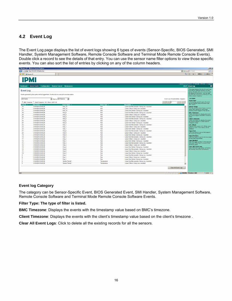
The Event Log page displays the list of event logs showing 6 types of events (Sensor-Specific, BIOS Generated, SMI Handler, System Management Software, Remote Console Software and Terminal Mode Remote Console Events). Double click a record to see the details of that entry. You can use the sensor name filter options to view those specific events. You can also sort the list of entries by clicking on any of the column headers.
Event log Category
The category can be Sensor-Specific Event, BIOS Generated Event, SMI Handler, System Management Software, Remote Console Software and Terminal Mode Remote Console Software Events.
Filter Type: The type of filter is listed.
BMC Timezone: Displays the events with the timestamp value based on BMC’s timezone.
Client Timezone: Displays the events with the client’s timestamp value based on the client’s timezone .
Clear All Event Logs: Click to delete all the existing records for all the sensors.

Version 1.0
17
5. Configuration
This group of pages allows you to access various configuration settings for the IPMI service. Configuration options include: DNS, mouse mode, network, network link, NTP, PEF, Services, SMTP, SSL, users.
5.1 DNS
The Domain Name System (DNS) is a distributed hierarchical naming system for computers, services, or any resource connected to the Internet or a private network. It associates the information with domain names assigned to each of the participants. Most importantly, it translates domain names to be meaningful to humans into the numerical (binary) identifiers associated with networking equipment for the purpose of locating and addressing these devices worldwide.
To configure the DNS settings on the IP KVM-IC2300, follow these steps:
1. Choose the Host Configuration from either Automatic or Manual
2. Enter the Host Name in the given field if you have chosen Manual Configuration.
3. Under Register BMC, Check the option Register BMC to register with this DNS settings and then Choose the option Direct Dynamic DNS to register with direct dynamic DNS or choose DHCP Client FQDN to register with DHCP server.
4. In the Domain name Configuration Settings, select the domain settings from the dropdown list. If you choose Manual, enter the DNS names manually in the given field.
5. In IPv4/IPV6 Domain Name Server Configuration, select the DNS Server Settings from the dropdown list: enter the preferred IP address for the Preferred DNS Server. Enter the alternate address In the Alternate

Version 1.0
18
DNS Server field.
6. Click Save to save the entries or reset to reset the changes.
5.2 Mouse Mode
The Redirection Console handles mouse emulation from local window to remote screen in two methods. The user has to be an Administrator to configure this option.
Select one from the two following modes:
Absolute Mode: The absolute position of the local mouse is sent to the server.
Relative Mode: The calculated relative mouse position displacement is sent to the server
Save: Click to save any changes made.
Reset: Click to Reset the modified changes.
5.3 Network
The network page allows you to configure the Ethernet interface for the IPMI service.

Version 1.0
19
To configure the network settings of the LAN interface for the IPMI service, follow these steps:
1. Select the designated Ethernet interface for IPMI. The MAC address will be displayed automatically.
2. For IPV4 Configurations: Use either one of the following connection method:
Obtain an IP Address automatically: This option is to dynamically configure IPv4 address using DHCP (Dynamic Host Configuration Protocol).
Enter the IP Address. This defines the IP address of local port and it has to be a private one. For example, 10.x.x.x or 192.x.x.x may be chose as they are reserved for LAN use. Enter the Subnet Mask and the default gateway’s IP address.
3. For IPv6 Configurations:
IPv6 Settings: This option is to enable the IPv6 settings in the device. Obtain an IPv6 address automatically: This option is to dynamically configure IPv6 address using DHCP (Dynamic Host Configuration Protocol).
IPv6 Address: To specify a static IPv6 address to be configured to the device. Eg: 2001:db8:3333:4444: 5555:6666:7777:8888
Subnet Prefix length: To specify the subnet prefix length for the IPv6 settings. Enter an integer between 1-128
Default Gateway: Specify v6 default gateway in IPv6 address format.
4. VLAN Configuration:
VLAN Settings: Check this box to enable the VLAN support for selected interface.
VLAN ID: The Identification for VLAN configuration. Enter an integer between 1 to 4095.

Version 1.0
20
VLAN Priority: The priority for VLAN configuration. Enter an integer between 1 to 7. Save: Click to save the entries.
Reset: Click to reset the modified changes.

Version 1.0
21
5.4 Network Link
The network link configures the data link settings for the IPMI network communication.
To configure the network link settings, follow these steps:
1. LAN Interface: Select the required network interface from the list with which the Link speed and duplex mode can be configured.
2. Auto Negotiation: Select this option to allow the device to perform automatic configuration to achieve the best possible mode of operation (speed and duplex) over a link. Or your can enter the information manually as described below.
3. Link Speed: Select the supported capabilities of the network interface. It can be 10/100/1000 Mbps.
4. Duplex Mode: The Duplex Mode could be either Half Duplex or Full Duplex.
5. Save: Click to save the settings or click Reset to reset the modified changes.

Version 1.0
22
5.5 NTP
The Network Time Protocol (NTP) is a protocol for synchronizing the clocks of computer systems with the a time server over a network.
To configure the NTP settings or manually enter the date and time, follow these steps:
1. Date: To specify the current date for the device. Uncheck the Automatically Synchronize box as described below to be able to enter this field manually.
2. Time: Specify the current Time for the device.
3. NTP Server: Specify the NTP Server for the device.
4. UTC Timezone: Specify your time zone in order to display to exact local time.
5. Automatically synchronize: Check the box to automatically synchronize the Date and Time with the NTP Server.
6. Refresh: Click reload the current date and time settings.
7. Save: Click to save the settings.
8. Reset: Click to reset the modified changes.

Version 1.0
23
5.6 PEF Management
Platform Event Filtering (PEF) provides a mechanism for configuring the IPMI service to take selected actions (defined as Event Filter Action) on a generated event. These actions include operations such as system power-off, system reset, as well as triggering an alert. The BMC scans all entries in the table and collects a set of actions to be performed as determined by the entries that were matched. Note that Event Filtering function is independent of Event Logging.
3 management tasks on the specified event can be configured through PEF: Event Filter, Alert Policy, and LAN Destination. To access them, click their tabs. 5.6.1 Event Filter Tab
A PEF implementation is recommended to provide at least 16 entries in the event filter table. You can filter an event{s) based on the sensor type, sensor name as well as the event description to perform certain actions when this event happens.
The fileds of Event Filter are explained below:
PEF ID: displays the ID for the newly configured PEF entry (read-only).
Filter configuration: indicates whether the PEF setting is enabled or disabled.
Event Filter Action: indicates the action to perform on this event.
Event Severity: the event severity defined by the administrator.
Sensor Name: the particular sensor about which the event is generated.
Add: Click to add a new event filtert.
Modify: Click to modify an existing entries.

Version 1.0
24
Cancel: Click to cancel the modification and return to Event filter list.
To add an event filter entry, select a free slot and click Add to open the Add event Filter entry Page. A sample screenshot of Add Event Filter Page is displayed in the screenshot below.
1. In the Event Filter Configuration section: PEF ID displays the ID for configured PEF entry (read-only).
2. Check the Filter Configuration box to enable the PEF settings.
3. For Event Severity, select any one of the Event severity from the list.
4. In the Filter Action configuration section, Event Filter Action is a mandatory field and the enable PEF Alert action (read-only) is checked by default.

Version 1.0
25
5. Select any of the Power action from the list: Power down, Power reset or Power cycle. The filter action is triggered by the sensors configured from the following Sensor Configuration section.
6. Choose any one of the configured alert policy number from the drop-down list.
NOTE: The Alert Policy has to be configured via the Alert Policy tab under Configuration->PEF->Alert Policy.
7. In the Generator ID configuration section, check Raw Data option to fill the Generator ID with raw data.
8. Enter the raw Generator ID1 data for Generator ID 1.
9. Enter the raw Generator ID2 data for Generator ID 2.
NOTE: In RAW data field, specify hexadecimal value with prefix '0x'.
10. In the Event Generator section, choose the event generator as Slave Address - if event was generated from IPMB. Or as System Software ID - if event was generated from system software.
11. In the Slave Address/Software ID field, specify corresponding I2C Slave Address or System Software ID.
12. Choose the particular channel number that the event message was received over. Or choose '0' if the event message was received via the system interface, primary IPMB, or internally generated by the BMC.
13. Choose the corresponding IPMB device LUN if the event is generated by IPMB.
14. In the Sensor configuration section, select the Sensor Type that will trigger the event filter action.
15. Choose the particular sensor from the sensor list for the Sensor Name.
16. Choose Event Option to be either All Events or Sensor Events. If the Sensor Events is selected, you need to specify the current reading for the specified threshold value at which the event is generated.
17. In the Event Data configuration section, the Event Trigger is used to give Event/Reading type value. Enter an integer from 1 to 255 ( FFh = match any).
18. Event Data 1 AND Mask field is used to indicate a wildcarded or compared bits. Valid data is from 0 to 255.
0 is a Wildcard bit: drop this bit position in the Event Data byte of the comparison. Corresponding bit position must be a 1 in Compare1 and a 0 in Compare 2. (Note: setting a 0 in this bit, a 1 and compare1 and a 1 in Compare 2 guarantees that you will never have a match.)
1 is a compared bit: use this bit for further exact or non-exact comparisons based on the following Compare1 and Compare2 values.
Each time the BMC receives an event message, it compares the event data against the entries in the event filter table. To match any Event Data filed value, just set the corresponding AND Mask, Compare 1 and Compare2 fields to 00h.
19. Event Data 1 Compare 1: used for indicating whether each bit position’s comparison is an exact comparison or not. Here, ‘test value’ refers to the Event Data value after the AND mask has been applied.
1 means to match bit in the test value exactly to correspond bit position in Compare 2.
0 means to match if corresponding bit in the test value matches corresponding bit in Compare 2.
20. Event Data 1 Compare 2 field is used to indicate whether each bit position's comparison is an exact comparison or not. Valid data is from 0 to 255.

Version 1.0
26
1 means to match a ‘1’ in corresponding bit position in test value.
0 means to match a ‘0’ in corresponding bit position in test value.
Example for Mask and Compare Bit:
Matching (bit 2 =1 ) OR (bit 1=1), and ignore all other bits.
AND Mask 0000 0110 Force all bits except bits 2 and 1 to 0.
Compare1 1111 1001 Compare for at least one of bit 2 or bit 1 being polarity specified in the corresponding bit position in Compare 2. Compare all other bits exactly.
Compare2 0000 0110 Compare for bit2 or bit1 =1, and remaining bits =0 exactly.
21. For Event Data2 AND Mask and Even Data 2 Compare1/2, use the same procedures as for Event Data 1.
22. Click add to add this new event filter entry. Or click Reset to reset the entry. Or Cancel to cancel this entry.
5.6.2 Alert Policy Tab
This page is for configuring the Alert Policy. The Alert Policy is specified in the previous Event Filter entry to select what alert policy is used when a match occurs. An alert policy is a collection of one or more alert destinations. An alert policy can support a mix of different alert destination types and channels. For example, one policy (uniquely identified by Policy Number not Policy Entry Number) could include event alerts and SMTP traps to send to different locations. This Alert Policy mechanism also makes it possible for different alert policies to be associated with different classes/types of events. You can add, delete or modify an entry on this page.
The fields of the Alert Policy entries are explained below: Policy Entry #: displays the order of the Alert Policy entry which also determines the oder or priority of the multiple alert destinations.

Version 1.0
27
Policy Number: displays the policy number of the configuration.
Policy Configuration: indicates whether this policy is enabled or disabled.
Policy Set: It shows how the event should be sent to (multiple) destinations depending on the following described circumstances.Configured according to the following rule set:
0 - Always send alert to this destination.
1 - If alert to previous destination was successful, do not send alert to this destination. Proceed to next entry in this policy set.
2 - If alert to previous destination was successful, do not send alert to this destination. Do not process any more entries in this policy set.
3 - If alert to previous destination was successful, do not send alert to this destination. Proceed to next entry in this policy set that is to a different channel.
4 - If alert to previous destination was successful, do not send alert to this destination. Proceed to next entry in this policy set that is for a different destination.
Channel Number: indicates a particular channel from the available channel list.
Destination Selector: indicates a particular destination from the configured destination list.
NOTE: The LAN Destination has to be configured on the LAN Destination tab under Configuration->PEF->LAN Destination.
To add or modify an Alert Policy entry, follow these steps:
1. In the Alert Policy Tab, select the entry number that you want to modify or click an empty slot to add a new
entry. The entry number just denotes the order or sequence of sending the alert in a given policy set. It is different from the Policy Number which doesn’t have to be equal to Policy Entry#. The Policy Number can also appear more than 1 time in the entries; therefore, you can define a more sophisticated rule for sending event alert to different channel or LAN destinations (see LAN Destination Tab in Section 5.6.3) for the
Version 1.0
28
same Policy Number.
2. Policy Entry #: Displays Policy entry number (read-only).
3. Policy Number: Displays the Policy number of the configuration. This number corresponds to the Alert Policy Number field in the modify/add Event Filter entry (see section 5.6.1 above).
4. Policy Configuration: Select to enable the policy settings.
5. Policy Set: Select any one of the Policy set values from the list. It defines how the alert should be sent to the (multiple) destinations depending on the following described rules. The priority of multiple LAN destinations is determined by the Policy Entry #.
0 - Always send alert to this destination.
1 - If alert to previous destination was successful, do not send alert to this destination. Proceed to next entry in this policy set.
2 - If alert to previous destination was successful, do not send alert to this destination. Do not process any more entries in this policy set. 3 - If alert to previous destination was successful, do not send alert to this destination. Proceed to next entry in this policy set that is to a different channel.
4 - If alert to previous destination was successful, do not send alert to this destination. Proceed to next entry in this policy set that is to a different destination type.
6. Channel Number: Choose a particular channel from the available channel list.
7. Destination Selector: Choose a particular destination from the configured destination list.
NOTE: The LAN Destination has to be configured via the LAN Destination tab under Configuration->PEF->LAN Destination.
8. Enable the check box if the Alert policy entry is Event Specific.
9. Choose any value that is used to look up the Alert String to send for this Alert Policy entry. If the Event specific is selected (above), then the value is used in conjunction with Event filter Number to lookup the Alert String from the PEF configuration Parameters. If the Event Specific is not selected, it directly selects an alert string from the PEF Configuration Parameters.
The Alert String is used for a Dial Page. The combination of Event Filter Entry and alert destination are used to select a given Alert String from a set of strings kept in the PEF (Platform Event Filtering) configuration parameters. This enables different strings to be sent based on what event filter was matched and where the alert is being sent.
NOTE: The PEF Configuration Parameters are set by the PEF commands which configure and control the Platform Event Filtering (PEF) and Alerting capabilities. For more information, contact Lanner
10. Click Add to add the new event filter entry or Cancel to cancel this entry and return to Event filter list

Version 1.0
29
5.6.3 LAN Destination
This page will let you configure the LAN destination to send the filtered event based on the rule set by the above Alert Policy Set.
The fields of the LAN Destination entries are explained below:
LAN Destination: Displays Destination number for entry (read-only).
Destination Type: Destination type can be either an SNMP Trap or an Email alert.
Destination Address: If Destination type is SNMP Trap, then the displayed IP address will receive the alert. Destination address can support the following IP address format:
- IPv4 address format.
- IPv6 address format.
If Destination type is Email Alert, it will display the email address that will receive the alert message.
To add an LAN Destination entry, follow these steps:

Version 1.0
30
1. In the LAN Destination Tab, choose the slot to be configured. The slot number should correspond to the
number that you have configured for the Destination Selector in the Alert Policy Entry. That is, if you choose the Destination Selector as 4 in the Alert Policy Entry page of Alert Policy Tab, then you have to configure the 4th slot of LAN Destination Page.
2. Select the designated slot for adding the particular LAN Destination number and click Add. This opens the Add LAN Destination entry.
3. It shows the LAN Destination number (read-only) in the LAN Destination field.
4. Select either SNMP Trap or Email Alert for the Destination Type field.
5. In the Destination Address field, enter the destination IP address.
NOTE: If Destination type is Email Alert, specify the user account that will receive the email. The User Account can be accessed under Configuration->Users.
6. Select the User Name from the list of users.
7. Enter the subject in the Subject field,.
8. Enter the message in the Message field.
9. Click Add to add the new LAN destination or Cancel to cancel this new setting.

Version 1.0
31
5.7 Services
This page displays the basic information about services running on the IP KVM-IC2300. Only Administrator can modify the services.
The fields of Services Page are explained below.
Service Name: displays service name (read-only).
Current State: displays the current status of the service in either active or inactive state.
Interfaces: shows the interface on which the service is running.
Nonsecure Port: indicates the non secure port number for the service.
Secure Port: indicates the secure port number for the service.
Timeout: displays the session timeout value of the service. Modify: Click to modify the existing services.
To modify a service that the IP KVM-IC2300 hosts, follow these steps:

Version 1.0
32
1. Select a slot and click Modify to modify the configuration of the service. Alternatively, double click on the
slot.
NOTE: When the configuration is modified, the service will be restarted automatically. User has to close the existing opened session for the service if needed. This opens the Modify Service screen as shown below.
2. Service Name is a read-only field.
3. Activate the Current State by enabling the Activate check box.
4. Choose any one of the available interfaces from the Interface drop-down list.
5. Enter the Nonsecure port number in the Nonsecure Port field.
6. Enter the Secure Port Number in the Secure Port field. Enter the timeout value in the Timeout field. For web, SSH and telnet service, user can configure the session timeout value.
7. Enter the maximum number of sessions allowed in the Maximum Sessions field.
8. Click Modify to save the entered changes or Cancel to exit and return to the Services Page. .
5.8 SMTP Settings
Simple Mail Transfer Protocol (SMTP) is an Internet standard for electronic mail (e-mail) transmission across Internet Protocol (IP) networks.
Version 1.0
33
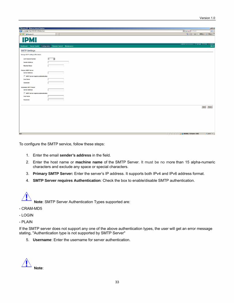
To configure the SMTP service, follow these steps:
1. Enter the email sender’s address in the field.
2. Enter the host name or machine name of the SMTP Server. It must be no more than 15 alpha-numeric characters and exclude any space or special characters.
3. Primary SMTP Server: Enter the server’s IP address. It supports both IPv4 and IPv6 address format.
4. SMTP Server requires Authentication: Check the box to enable/disable SMTP authentication.
Note: SMTP Server Authentication Types supported are:
- CRAM-MD5
- LOGIN
- PLAIN
If the SMTP server does not support any one of the above authentication types, the user will get an error message stating, "Authentication type is not supported by SMTP Server"
5. Username: Enter the username for server authentication.
Note:

Version 1.0
34
-The User Name can be of length 4 to 64 alpha-numeric characters.
- It must start with an alphabet.
- Special characters ','(comma), ':'(colon), ';'(semicolon), ' '(space) and '\'(backslash) are not allowed.
6. Password: The password for the SMTP User Account.
Note:
- The Password must be at least 4 characters long and no more than 64 characters.
- Space is not allowed.
7. Secondary SMTP Server: It is an optional field. Enter the information if there a secondary server.
8. Save: Click to save the new SMTP server configuration or Reset to reset the modified changes.
5.9 SSL
The Secure Socket Layer protocol was created by Netscape to ensure secure transactions between web servers and client browsers. The protocol uses a third party, a Certificate Authority (CA), to identify one end or both end of the transactions.
There are three tabs representing 3 SSL functions to be accessed through this page:
Upload SSL option is used to upload the certificate and private key file into the BMC.
Generate SSL option is used to generate the SSL certificate based on configuration details.
View SSL option is used to view the uploaded SSL certificate in readable format.

Version 1.0
35
5.9.1 Upload SSL
To upload an SSL certificate, follow these steps:
1. Current Certificate: Current certificate information will be displayed (read-only).
2. New Certificate: Click to locate your certificate file which should be of pem type
3. Current Privacy Key: Current privacy key information will be displayed (read-only).
4. New Privacy Key: Click to locate the privacy key file.
5. Upload: Click to locate the privacy key into the BMC.
6. Click Upload to upload the certificate and privacy key.

Version 1.0
36
5.9.2 Generate SSL
To generate an SSL certificate, follow these steps:
1. Common Name (CN): Enter the common name for which the certificate should be generated. It should be
no more than 64 characters. Special characters such as “#” and “$” are not allowed.
2. Organization (O): Enter the organization name for which the certificate is to be generated. It should be no longer than 64 characters. Special characters such as “#” and “$” are not allowed.
3. Organization Unit (OU): Enter the name of the organization section unit for which the certificate is to be generated.
4. City of Locality (L): City or Locality of the organization (mandatory). It should be no longer than 64 characters. Special characters such as “#” and “$” are not allowed.
5. State or Province (ST): State or Province of the organization (mandatory). It should be no longer than 64 characters. Special characters such as “#” and “$” are not allowed.
6. Country (C): Country code of the organization (mandatory). It contains only two characters and specifal characters are not allowed.
7. Email Address: Enter the email Address of the organization (mandatory).
8. Valid for: Enter the valid period from 1 to 3650 days.
9. Key Length: The SSL key length in bit.
10. Generate: Click to generate the new SSL certificate.
Note: The HTTP service will restart.

Version 1.0
37
5.9.3 View SSL
The view SSL page displays the following information about the SSL certificate.
Basic Information: This section displays the basic information about the uploaded SSL certificate. It displays the following fields.
• Version
• Serial Number
• Signature Algorithm
• Public Key
Issued From: This section describes the following Certificate Issuer information
• Common Name (CN)
• Organization (O)
• Organization Unit (OU)
• City or Locality (L)
• State or Province (ST)
• Country(C)
• Email Address

Version 1.0
38
Validity Information: This section displays the validity period of the uploaded certificate.
• Valid From
• Valid To
Issued To: This section display the information about the certificate issuer.
• Common Name(CN)
• Organization(O)
• Organization Unit(OU)
• City or Locality(L)
• State or Province(ST)
• Country(C)
• Email Address

Version 1.0
39
5.9.4 Users
The User Management page allows you to view the current user account to access the IPMI web interface.
You can also add, modify, and delete a current user.

Version 1.0
40
To add a new user, follow these steps:
1. Click on a free slot and click the Add User button.
2. Enter a name for the user in the User Name.
Note: -The User Name should contain 4 to 16 alpha-numeric characters.
-It must start with an alphabetical character and must be case-sensitive.
- Special characters like '(comma), '.'(period), ':'(colon), ';'(semicolon), ' '(space), '/'(slash), '\'(backslash), ' ('(left bracket) and ')'(right bracket) are not allowed.
3. Enter the Password in the Password field. And retype the password again to confirm the password.
Note: The password should be at least 8 characters and no longer than 20 characters. No space is allowed.
4. Check the box to enable or disable the User Access privilege.
5. Select the privilege level for the network privilege. The users has the following privilege level:
User: The User group can only access the Dashboard and Server Health menus with read-only privilege.
Operator: The operator group can access all menus but cannot modify any configurations.
Administrator: All menus can be accessed and all configurations can be modified on the menu including the console redirection function.
OEM Proprietary: The user access level defined by OEM.

Version 1.0
41
No Access: Login access denied.
6. Enter the Email ID of the user in the Email ID field. If the user forgets the password, the new password will be mailed to the configured email address.
7. Email Format: Two types of email formats are available:
AMI-Format: The subject of this mail format will be 'Alert from (your Hostname)'. The mail content shows sensor information, ex: Sensor type and Description.
Fixed-Subject Format: This format displays the message according to user's setting. You must set the subject and message for email alert.
8. Click Browse to locate the SSH key file. SSL key file should be of public type.
9. Click Add to save the new user or Cancel to cancel the modification and return to the users list.

Version 1.0
42
6. Remote Control
The Remote Control Group consists of the following two items.
• Console Redirection
• Server Power Control
6.1 Console Redirection
The remote console application allows you to control your server's operating system remotely by using the client’s screen, mouse, and keyboard. The Console redirection can also redirect the local CD/DVD, Floppy diskette and Hard disk/USB thumb drives as if they were installed directly on the server. It requires the installation of Java Runtime Environment. The following list the supported client OS for console redirection:
Supported Client OS:
winxp
w2k3 - 32 bit
w2k3 - 64 bit
RHEL 4 - 32 bit
RHEL 4 - 64 bit
RHEL 5.4 - 32 bit
RHEL 5.4 - 64 bit
RHEL 6.0 - 64 bit
RHEL 6.0 - 32 bit
Ubuntu 9.10 LTS - 32
Ubuntu 9.10 LTS - 64
Ubuntu 8.10 -32
Ubuntu 8.10 -64
OpenSuse 11.2 -32
OpenSuse 11.2 -64
FC 9 - 32
FC 9 - 64
FC 10 - 32
FC 10 - 64
FC 12 - 32
FC 12 - 64
FC 13 - 32
FC 13 - 64

Version 1.0
43
FC 14 - 32
FC 14 - 64
MAC -32
MAC-64
The following list the supported Host OS for console redirection:
Supported Host OS
RHEL 5
RHEL 6
w2k3
w2k8
RHEL 4
OpenSuse 11.2
OpenSuse 10.x
Ubuntu 8.10
Ubuntu 9.10
Ubuntu 11.04

Version 1.0
44
6.2 Java Console
This is an OS independent plug-in which can be used in Windows as well as Linux with the help of JRE. JRE should start downloading and installing in the client’s system after clicking this button. The remote console redirection function can be accessed through the JViewer program. For more information on the JViewer program, refer to Chapter 8.

Version 1.0
45
Server Power Control This page allows you to view and control the power of the managed server.
To configure the power setting, choose any of the power settings from the following:
Reset Server: This option will reboot the system without powering off (warm boot).
Power Off Server - immediate: This option will power off the server immediately.
Power Off Server – Orderly Shutdown: This option will initiate operating system shutdown prior to shutdown.
Power on Server: This option will power on the server.
Power Cycle Server: This option will first power off the system, and then reboot it (cold boot).
Perform Action: Click this option to perform the selected operation.

Version 1.0
46
7. Maintenance
This group of pages allows you to do maintenance tasks on the managed server. The menu contains the following items:
Firmware Update Restore Factory Defaults Preserve Configuration
7.1 Firmware Update
This page can be used to update the system’s firmware.
To update your firmware, follow these steps: Click the Enter Update Mode to walk you through the process of firmware update. You will be guided through the following process:
Closing all active client requests. Preparing device for firmware upgrade. Uploading firmware image. Verifying firmware image. Flashing firmware image.

Version 1.0
47
Caution: The firmware upgrage process is a crucial operation. Make sure that the power or connectivity loss are prevented during the process.
Note: Even through the update process will give the option to preserve firmware settings, it is advised to write down the firmware configurations as a backup.
7.2 Restore Factory Defaults
This page is used to restore the factory defaults of the device firmware.
To restore the device to its factory defaults, follow these steps:
Click the Restore Factory to restore the factory defaults of the system’s firmware.

Version 1.0
48
7.3 Preserve Configuration This page is used to configure the system settings that will be preserved after the firmware update.
To configure the IPMI preservation settings, follow these steps:
1. SDR: Sensor Data Record. For more information, refer to IPMI specification. 2. SEL: Sensor Event Log. For more information, refer to 4.2 Event Log 3. IPMI: IPMI related configuration. For more information, refer to IPMI specification. 4. NTP: Network Time Protocol. For more information, refer to 5.5 NTP 5. Service: Services. For more information, refer to 5.7 Services.

Version 1.0
49
8. JViewer
The JViewer is the program windows of the console redirection function. It consists of the following menus:
Video
Keyboard
Mouse
Options
Media
Keyboard Layout
Video Record
Help
A detailed explanation of these menu items are given below.
8.1 Video
This menu contains the following sub menu items.
Pause redirection: This option is used for pausing Console Redirection.
Resume Redirection: This option is used to resume the Console Redirection when the session is paused.

Version 1.0
50
Refresh Video: This option can be used to update the display shown in the Console Redirection window.
Compression Mode: Select the compressions /decompresion algorithm. The default is YUV444+4ColorsVQ.
DCT Quantization Table: Select the video quality of the client screen display. The default is 4.
Host Video Output: If you disable this option, the host server display will be blank but you can still view the screen in Console Redirection. If you enable this option, the display will be back on the server screen.
Full Screen: This option is used to view the Console Redirection in full screen mode (Maximize). This menu is enabled only when both the client and host resolution are same.
Exit: This option is used to exit the console redirection screen.
8.2 Keyboard
This menu contains the following sub menu items.
Hold Right Ctrl Key: This menu item can be used to send the command of holding the right-side <CTRL> key in Console Redirection.
Hold Right Alt Key: This menu item can be used to send the command of holding the right-side <ALT> key in Console Redirection.
Hold Left Ctrl Key: This menu item can be used to send the command of holding the left-side <CTRL> key in Console Redirection.
Hold Left Alt Key: This menu item can be used to send the command of holding the left-side <ALT> key in Console Redirection.
Left Windows Key: This menu item can be used to sned the command of pressing the left-side <WIN> key in Console Redirection. You can also decide how the key should be pressed: Hold Down or Press and Release.
Right Windows Key: This menu item can be used to send the command of the right-side <WIN> keyn in Console Redirection. You can also decide how the key should be pressed: Hold Down or Press and Release.
Alt+Ctrl+Del: This menu item can be used to send the reboot command –holding down <CTRL>, <ALT> and <DEL>to the server that you are redirecting.
8.3 Mouse
Show Cursor: This menu item can be used to show or hide the local mouse cursor on the remote client system.
Mouse Calibration: This menu item can be used only if the mouse mode is relative.
In this step, the mouse threshold settings on the remote server can be configured. The local mouse cursor is displayed in RED color and the remote cursor is shown on the remote video screen. Both cursors will be synchronized at the beginning. Please use '+' or '-' keys to change the threshold settings until both cursors go out of synch. Note the first reading on which cursors go out of synch. Once this is detected, use 'ALT-T' to save the threshold value.
8.4 Options
Bandwidth: The Bandwidth Usage option allows you to adjust the bandwidth. You can select one of the following:
Auto Detect - This option is used to detect client system keyboard layout automatically and send the key event

Version 1.0
51
to the host based on the Layout detected. 256 Kbps 512 Kbps 1 Mbps 10 Mbps
Keyboard/Mouse Encryption: This option allows you to encrypt keyboard inputs and mouse movements sent between the connections.
Zoom:
Note: This option is available only when you launch the Java Console.
Zoom In – For increasing the view of the screen with an increment of 10% Zoom Out – For decreasing the view of the screen with an increment of 10%
8.5 Media
Virtual Media Wizard:
To add or modify a media, select and click 'Virtual Media Wizard' button, which pops out a window named “Virtual Media” where you can configure the media. A sample screenshot of Virtual media screen is displayed below.
Floppy Key Media: This function can be used to start or stop the redirection of a physical floppy drive and floppy image (in img file format).
CD/DVD Media: This function can be used to start or stop the redirection of a physical DVD/CD-ROM drive and cd image (in iso file format).

Version 1.0
52
Hard disc/USB Key Media: This function can be used to start or stop the redirection of a HD/USB image and USB drives.
Note: -For Linux client, fixed hard drive is redirected only in Read Mode. It is not Write mode supported.
-For USB key image redirection, it supports FAT 16, FAT 32 and NTFS file format

Version 1.0
53
8.6 Keyboard Layout Auto Detect: This option is used to detect keyboard layout automatically. The languages supported are English – US, French – France, Spanish – Spain, German- Germany, and Japanese- Japan. If both the client and host languages are the same, then for all the languages other than English mentioned above, you must select this option to avoid errors.
Soft Keyboard: This option allows you to select the keyboard layout. It is similar to onscreen keyboard. If the client and host languages are different, then for all the languages other than English, you must select the appropriate language in the list of the menu and use the softkeyboard to avoid errors.
8.6.1 Video Record
Important: To view this menu option you must download the Java Media FrameWork (JMF). It can be downloaded from the link http://www.oracle.com/technetwork/java/javase/download-142937.html
Start Record: Click this option to start recording the screen.
Stop Record: Click this option is used to stop the recording.
Settings: Click this option to set the settings for video recording.
To configure the video settings, follow these steps:
1. Enter the Video Length in seconds.

Version 1.0
54
2. Browse and locate where you want the video to be saved.
3. Enable the Normalized video resolution to 1024X768.
4. Click OK to save the entries and return to the Console Redirection screen or click Cancel if you don’t want to save the changes.
5. In the Console Redirection window, click Video Record > Start Record.
6. Record the process.
7. To stop recording, click Video Record > Stop Record.