ip devices manual - michael ellerbeck | michael ellerbeck axxess® ip devices installation manual is...
TRANSCRIPT

Axxess IP DevicesInstallation Manual
®


©Inter-Tel, Inc. April 2006 printed in USA
INSTALLATION MANUAL
Revised April 2006
AXXESS® IP DEVICES
Part Number835.2195-18


The Axxess® IP Devices Installation Manual is released by INTER-TEL, INC. as a guide for certifiedservice personnel. It provides information necessary to properly install, program, operate, and maintainthe system.
The contents of this manual may include technical or other inaccuracies. Inter-Tel reserves the right tomake revisions or changes without prior notice. Some features or applications mentioned may require afuture release and are not available in the initial release. Future product features and applications aresubject to availability and cost. Some features or applications may require additional hardware and/orspecific software. Software packages released after the publication of this guide will be documented inaddenda to the manual or succeeding issues of the manual.
For additional information and/or technical assistance, certified technicians may contact:
Customer Support DepartmentINTER-TEL, INC.
7300 West Boston StreetChandler, AZ 85226-3224
188-777-EASY(3279)
If you have any questions or comments regarding this manual orother technical documentation, contact
Inter-Tel’s Technical Publications Department at:[email protected]
All products and services mentioned in this publication are the trademarks, service marks, registered marks, or registered service marks of theirrespective owners.Inter-Tel®, Axxess®, Unified Communicator®, and CommSource® are registered trademarks of Inter-Tel, Incorporated.Eclipse™ is a trademark of Inter-Tel, Incorporated.Microsoft® Windows® and ActiveSync® are registered trademarks of Microsoft Corporation.eCos™ is a trademark of Red Hat, Inc. AudioCodes™ is a trademark of AudioCodes Ltd. Intel® Pentium® are registered trademarks of Intel Corporation.PowerSense™ is a trademark of Red Hawk/CDT, Inc.WinZip® is a registered trademark of WinZip Computing, Inc.SpectraLink® is a registered trademark of SpectraLink Corporation.Cisco® is a registered trademark of Cisco Systems, Inc.Broadcom® is a registered trademark of Broadcom Corporation.
© Inter-Tel, Inc. April 2006 printed in USA
NOTICE
Part of the software embedded in this product is eCos - Embedded Configurable Operating System, a trademark of Red Hat.Portions created by Red Hat are Copyright (C) 1998, 1999, 2000 Red Hat, Inc. (http://www.redhat.com/). All RightsReserved.THE SOFTWARE IN THIS PRODUCT WAS IN PART PROVIDED BY RED HAT AND ANY EXPRESS OR IMPLIEDWARRANTIES, INCLUDING, BUT NOT LIMITED TO, THE IMPLIED WARRANTIES OF MERCHANTABILITYAND FITNESS FOR A PARTICULAR PURPOSE ARE DISCLAIMED. IN NO EVENT SHALL THE AUTHOR BE LIA-BLE FOR ANY DIRECT, INDIRECT, INCIDENTAL, SPECIAL, EXEMPLARY, OR CONSEQUENTIAL DAMAGES(INCLUDING, BUT NOT LIMITED TO, PROCUREMENT OF SUBSTITUTE GOODS OR SERVICES; LOSS OF USE,DATA, OR PROFITS; OR BUSINESS INTERRUPTION) HOWEVER CAUSED AND ON ANY THEORY OF LIABIL-ITY, WHETHER IN CONTRACT, STRICT LIABILITY, OR TORT (INCLUDING NEGLIGENCE OR OTHERWISE)ARISING IN ANY WAY OUT OF THE USE OF THIS SOFTWARE, EVEN IF ADVISED OF THE POSSIBILITY OFSUCH DAMAGE.


Table of ContentsAXXESS® IP DEVICES MANUAL – Revised, April 2006
Table of ContentsCONTENTS PAGE
1. Introduction . . . . . . . . . . . . . . . . . . . . . . . . . . . . . . . . . . . . . . . . . . . . . . . . . . . . . . . . . . 12. Changes and New Features . . . . . . . . . . . . . . . . . . . . . . . . . . . . . . . . . . . . . . . . . . . . . . 33. “Endpoints” and “Phones” . . . . . . . . . . . . . . . . . . . . . . . . . . . . . . . . . . . . . . . . . . . . . . 44. Firmware . . . . . . . . . . . . . . . . . . . . . . . . . . . . . . . . . . . . . . . . . . . . . . . . . . . . . . . . . . . . 5
A. IPRC Firmware Compatibilities . . . . . . . . . . . . . . . . . . . . . . . . . . . . . . . . . . . . . . . . 5B. Multi-Protocol Endpoint Firmware Compatibilities . . . . . . . . . . . . . . . . . . . . . . . . . 5
5. IP Network Specifications . . . . . . . . . . . . . . . . . . . . . . . . . . . . . . . . . . . . . . . . . . . . . . . 6A. Performance. . . . . . . . . . . . . . . . . . . . . . . . . . . . . . . . . . . . . . . . . . . . . . . . . . . . . . . . 6B. Bandwidth Utilization . . . . . . . . . . . . . . . . . . . . . . . . . . . . . . . . . . . . . . . . . . . . . . . . 8C. Processing Latency . . . . . . . . . . . . . . . . . . . . . . . . . . . . . . . . . . . . . . . . . . . . . . . . . 10D. Subnet Settings . . . . . . . . . . . . . . . . . . . . . . . . . . . . . . . . . . . . . . . . . . . . . . . . . . . . 11E. Operation Behind Firewalls or Proxies . . . . . . . . . . . . . . . . . . . . . . . . . . . . . . . . . . 13F. Port Configuration. . . . . . . . . . . . . . . . . . . . . . . . . . . . . . . . . . . . . . . . . . . . . . . . . . 16G. QoS Settings . . . . . . . . . . . . . . . . . . . . . . . . . . . . . . . . . . . . . . . . . . . . . . . . . . . . . . 20H. Application Programming . . . . . . . . . . . . . . . . . . . . . . . . . . . . . . . . . . . . . . . . . . . . 20
6. Virtual Local Area Network (VLAN) Tagging Support . . . . . . . . . . . . . . . . . . . . . 227. Quick Start Installation Outline . . . . . . . . . . . . . . . . . . . . . . . . . . . . . . . . . . . . . . . . . 268. Installing the IPRC . . . . . . . . . . . . . . . . . . . . . . . . . . . . . . . . . . . . . . . . . . . . . . . . . . . 279. System Database Programming . . . . . . . . . . . . . . . . . . . . . . . . . . . . . . . . . . . . . . . . . 3010. Installing the IP and Multi-Protocol Endpoints . . . . . . . . . . . . . . . . . . . . . . . . . . . . 32
A. Physical Interfaces. . . . . . . . . . . . . . . . . . . . . . . . . . . . . . . . . . . . . . . . . . . . . . . . . . 32B. Installation . . . . . . . . . . . . . . . . . . . . . . . . . . . . . . . . . . . . . . . . . . . . . . . . . . . . . . . . 41C. Power Supply Compatibilities. . . . . . . . . . . . . . . . . . . . . . . . . . . . . . . . . . . . . . . . . 43D. Wall Mounting . . . . . . . . . . . . . . . . . . . . . . . . . . . . . . . . . . . . . . . . . . . . . . . . . . . . 44E. IP Endpoint Status Displays . . . . . . . . . . . . . . . . . . . . . . . . . . . . . . . . . . . . . . . . . . 49F. Hardware Revision Identification . . . . . . . . . . . . . . . . . . . . . . . . . . . . . . . . . . . . . . 52G. Inter-Tel Protocol (ITP) Mode vs. SIP Mode . . . . . . . . . . . . . . . . . . . . . . . . . . . . . 53
11. Installing the IP SLA . . . . . . . . . . . . . . . . . . . . . . . . . . . . . . . . . . . . . . . . . . . . . . . . . . 5612. Updating Firmware . . . . . . . . . . . . . . . . . . . . . . . . . . . . . . . . . . . . . . . . . . . . . . . . . . . 58
A. Upload Utility Application . . . . . . . . . . . . . . . . . . . . . . . . . . . . . . . . . . . . . . . . . . . 58B. TFTP Download Application . . . . . . . . . . . . . . . . . . . . . . . . . . . . . . . . . . . . . . . . . 63C. TFTP Server . . . . . . . . . . . . . . . . . . . . . . . . . . . . . . . . . . . . . . . . . . . . . . . . . . . . . . 66D. Automated Boot Code Update . . . . . . . . . . . . . . . . . . . . . . . . . . . . . . . . . . . . . . . . 72E. Download Error Message Displays. . . . . . . . . . . . . . . . . . . . . . . . . . . . . . . . . . . . . 73
13. Programming the IP Devices on a v1.5.x Firmware IPRC . . . . . . . . . . . . . . . . . . . 80A. Learn Mode . . . . . . . . . . . . . . . . . . . . . . . . . . . . . . . . . . . . . . . . . . . . . . . . . . . . . . . 81B. Self-Programming Mode. . . . . . . . . . . . . . . . . . . . . . . . . . . . . . . . . . . . . . . . . . . . . 82C. HTTP/Web Interface Method . . . . . . . . . . . . . . . . . . . . . . . . . . . . . . . . . . . . . . . . . 84
Page v

Table of ContentsAXXESS® IP DEVICES MANUAL – Revised, April 2006
CONTENTS PAGED. RS-232 Connection Method (IPRC Only) . . . . . . . . . . . . . . . . . . . . . . . . . . . . . . 130E. Telnet Connection Method . . . . . . . . . . . . . . . . . . . . . . . . . . . . . . . . . . . . . . . . . . 131F. RS-232/Telnet Card Programming Fields. . . . . . . . . . . . . . . . . . . . . . . . . . . . . . . 133G. RS-232/Telnet Device Programming Fields . . . . . . . . . . . . . . . . . . . . . . . . . . . . . 135H. RS-232/Telnet IP Devices Programming Fields . . . . . . . . . . . . . . . . . . . . . . . . . . 138
14. Programming the IP Devices on a v8.2.x Firmware IPRC . . . . . . . . . . . . . . . . . . 141A. Self-Programming Mode (Models 8620/8622 and 8662 Only) . . . . . . . . . . . . . . 142B. IP Phone Web Client . . . . . . . . . . . . . . . . . . . . . . . . . . . . . . . . . . . . . . . . . . . . . . . 145C. TFTP Configuration Files . . . . . . . . . . . . . . . . . . . . . . . . . . . . . . . . . . . . . . . . . . . 158D. Axxess Database Programming . . . . . . . . . . . . . . . . . . . . . . . . . . . . . . . . . . . . . . 167E. Windows CE .NET Programming (Model 8690 Only). . . . . . . . . . . . . . . . . . . . . 168
15. IP Local Loop Support . . . . . . . . . . . . . . . . . . . . . . . . . . . . . . . . . . . . . . . . . . . . . . . 175A. System Database Programming . . . . . . . . . . . . . . . . . . . . . . . . . . . . . . . . . . . . . . 177B. AudioCodes MP-100 MGCP Gateway . . . . . . . . . . . . . . . . . . . . . . . . . . . . . . . . . 178C. AudioCodes MP-104 MGCP Gateway . . . . . . . . . . . . . . . . . . . . . . . . . . . . . . . . . 188D. AudioCodes MP-104 SIP Gateway. . . . . . . . . . . . . . . . . . . . . . . . . . . . . . . . . . . . 189
16. IP Softphone . . . . . . . . . . . . . . . . . . . . . . . . . . . . . . . . . . . . . . . . . . . . . . . . . . . . . . . . 190A. Axxess IP SoftPhone. . . . . . . . . . . . . . . . . . . . . . . . . . . . . . . . . . . . . . . . . . . . . . . 190B. Eclipse IP SoftPhone. . . . . . . . . . . . . . . . . . . . . . . . . . . . . . . . . . . . . . . . . . . . . . . 191C. Model 8602 . . . . . . . . . . . . . . . . . . . . . . . . . . . . . . . . . . . . . . . . . . . . . . . . . . . . . . 192
17. Troubleshooting . . . . . . . . . . . . . . . . . . . . . . . . . . . . . . . . . . . . . . . . . . . . . . . . . . . . . 193A. Connection Issues . . . . . . . . . . . . . . . . . . . . . . . . . . . . . . . . . . . . . . . . . . . . . . . . . 193B. Audio Issues . . . . . . . . . . . . . . . . . . . . . . . . . . . . . . . . . . . . . . . . . . . . . . . . . . . . . 195C. Echo Issues . . . . . . . . . . . . . . . . . . . . . . . . . . . . . . . . . . . . . . . . . . . . . . . . . . . . . . 198D. Multi-Protocol Endpoint-Related Issues . . . . . . . . . . . . . . . . . . . . . . . . . . . . . . . . 199E. VLAN Tagging-Related Issues . . . . . . . . . . . . . . . . . . . . . . . . . . . . . . . . . . . . . . . 205F. IPRC Diagnostics . . . . . . . . . . . . . . . . . . . . . . . . . . . . . . . . . . . . . . . . . . . . . . . . . 205
18. Part Numbers . . . . . . . . . . . . . . . . . . . . . . . . . . . . . . . . . . . . . . . . . . . . . . . . . . . . . . . 20619. FCC Information . . . . . . . . . . . . . . . . . . . . . . . . . . . . . . . . . . . . . . . . . . . . . . . . . . . . 20820. Glossary . . . . . . . . . . . . . . . . . . . . . . . . . . . . . . . . . . . . . . . . . . . . . . . . . . . . . . . . . . . . 208
Page vi

IntroductionAXXESS® IP DEVICES MANUAL – Revised, April 2006
1. INTRODUCTION
1.1 Inter-Tel® supports various Internet Protocol (IP) endpoints. These endpoints providethe functionality that allows you to make phone calls through the IP network to an IP ResourceCard (IPRC) on the Inter-Tel Axxess® system. The endpoints that support IP are as follows:
NOTE: For those individuals who are already familiar with the Issue 7 of the Axxess IP DevicesManual, Revised May 2005 (document part no. 835.2195-17), “change bars” like the one next tothis paragraph have been placed in the margins to indicate any new or revised information sincethe last revision of the IP Devices Manual.
Soft IP Endpoints
• Axxess IP SoftPhone: Operates like an Inter-Tel Executive endpoint on a PC and ter-minates on an IPRC (firmware v8.0 and earlier) in the system cabinet (see page 190 fordetails).
• Eclipse2™ IP SoftPhone: Operates like an Inter-Tel Professional endpoint on a PC andterminates on an IPRC (firmware v8.0 and earlier) in the system cabinet (see page 190for details).
• Model 8602: Operates like a Model 8662 multi-protocol endpoint and supports Inter-Tel Protocol (ITP) mode on a PC. It requires software v9.1 or later and IPRC firmwarev9.0.0 or later (see page 192 for details).
Hard IP Endpoints
• Axxess IP PhonePlus: Looks and operates like an Executive endpoint (see page 33 fordetails).
• Eclipse IP PhonePlus: Looks and operates like a Professional endpoint (see page 33for details).
• Model 8660: Looks and operates like a Model 8560 endpoint (see page 35 for details).
• IP Single-Line Adapter (IP SLA): Looks and operates like a standard SLA (seepage 56 for details).
• Models 8664, 8665, and 8668: Are wireless, handheld portable endpoints. These newendpoints operate like a Model 8660 endpoint and support Inter-Tel Protocol (IPT)mode. For details, refer to the NetLink SVP Server and Model 8664/8665 InstallationManual (part no. 935.4521).
Hard Multi-Protocol Endpoints
• Models 8600, 8620/8622, and 8662: Look and operate like Models 8500, 8520, and8560 endpoints, respectively. The main difference in the operation is that these end-points do not have red and green LEDs. These endpoints support Inter-Tel Protocol(ITP) or Session Initiation Protocol (SIP) mode. The available features vary dependingon the mode the endpoint is in. (See page 36 for details.)
• Model 8690: Unlike traditional Inter-Tel endpoints that have buttons built into the plas-tics, the Model 8690 has a touch screen that displays feature, dialpad, and menu but-tons. This endpoint also supports ITP or SIP mode (see page 39 for details).
Soft SIP Endpoints
• Model 8601 SoftPhone for Pocket PC: Is a software-based SIP softphone that runs onselected Pocket PC 2002 (or later) Personal Digital Assistant (PDA) platforms. Forinformation about installation and programming, refer to the Model 8601 SoftPhone forPocket PC Installation Manual (part no.835.2736).
Page 1Introduction

IntroductionAXXESS® IP DEVICES MANUAL – Revised, April 2006
NOTE: IP Devices firmware Version 1.3 or later does not support the IP Card (IPC), part num-ber 550.2260. For details about the IPC, refer to the IPC Installation and Programming Manual(document part no. 835.2554).
1.2 Except for the features listed in the bullets below, hard IP endpoints and multi-protocolendpoints that are configured to use Inter-Tel Protocol (ITP) operate the same as traditionalendpoints such as the Executive endpoint, which are installed directly on the telephone system.Hard multi-protocol endpoints that are configured to use SIP also operate similar to traditionalendpoints except that they have a reduced feature set (see page 53). The following lists the fea-tures and applications that are not supported on hard IP and multi-protocol endpoints.
Hard IP and multi-protocol endpoints:
• cannot use a PC Data Port Module (PCDPM) or Modem Data Port Module (MDPM).
• do not support Desktop Open Architecture Interface (OAI) applications.
• do not have a secondary voice path and cannot support Off-Hook Voice Announce(OHVA).
• do not support Enhanced Speakerphone Mode (except the Models 8600, 8664, and8665).
• that are in SIP mode do not support Attendant Console.
1.3 The IP device interface to telephone system is an Ethernet IEEE 802.3 100Mbpsunshielded twisted pair (UTP) interface (RJ-45). The IPRC and hard IP and multi-protocolendpoints use flash memory and their software can be updated over the Local Area Network(LAN).
CAUTION
Important Note for Administrators for Emergency Calls: Unless programmed for emer-gency outgoing access using a local loop (see page 175), when an IP endpoint such as theModel 8602, dials the emergency number, this includes 911 (default for US systems), 999(default for European systems), or the appropriate emergency dial sequence for the locality,from a remote location, the call will be placed from where the phone system is physicallylocated. Since these emergency services use Caller ID (CLIP) to help location the caller,emergency service could be misdirected or delayed. Also, the emergency service contactedmay be local to the phone system, but not to the IP device. All IP device users should bealerted to this situation and instructed to use a local telephone line for placing emergencycalls. Also note that the IP device may not function in the event of a power or network fail-ure at either the local site or the phone system location unless operational backup powerprovisions have been implemented by the installing company.
Page 2 Introduction

Changes and New FeaturesAXXESS® IP DEVICES MANUAL – Revised, April 2006
2. CHANGES AND NEW FEATURES
2.1 The major enhancements described below:
• Network Address Translation (NAT) Traversal for IP Endpoints: The Axxess sys-tem now supports traversing near-end NAT using statically assigned NAT addresses.This capability allows an Axxess system to be placed inside a NAT or firewall and stillcommunicate with IP endpoints outside the NAT/firewall. With system v9.1 or later,you can program each IP endpoint to use either the Native address or the NAT addressin Database Programming. In other words, the system could be programmed with corre-sponding IP addresses for communicating with each IP endpoint, whether the endpointwas located inside or outside the NAT/firewall. You can also program an IP endpoint tobe moved inside or outside the firewall (NAT) automatically without programmingintervention. This is called “Automatic NAT Detection.” For details about NAT tra-versal and Automatic NAT Detection, refer to the v9.1 Addendum to Issue 9.0 of theInter-Tel Axxess Installation and Maintenance Manual (part no. 550.8029).
• New Model 8668: Is a wireless, handheld portable endpoint. This endpoint is the Indus-trial Enterprise version of the Model 8664 which provides increased damage resistanceand a longer warranty. For details, refer to the NetLink SVP Server and Model 8664/8665 Installation Manual (part no. 935.4521).
• New Model 8602: Is a softphone application that enables Voice over IP (VoIP) tele-phone calls from laptops or desktop computers. The Model 8602 connects to the Inter-Tel® telephone system through an existing IP network. The Model 8602 operates like aModel 8662 endpoint and supports Inter-Tel Protocol (ITP) mode. (see page 192).
• Updated Port Configuration: The Port Configuration table has been updated in thisrelease (page 16).
• New Plastic Rivets: As of May 2005, the 8600 series IP endpoints were changed tomake the metal plate easier to remove from the baseplate for wall mounting or cablemanagement. To compensate for the reduced force now required to remove the metalplate, two plastic rivets were added to secure the metal plate to the baseplate located onthe bottom of each endpoint. If the metal plate is removed for cable management, Inter-tel recommends the rivets be reinserted after the metal plate is reassembled onto thebaseplate of the endpoint, to lock it into place (see page 41).
• This manual contains a new section called “Endpoints and Phones.” This section helpsyou to understand the usage of the terms “endpoint” and “phone” (see page 4).
Page 3Changes and New Features

“Endpoints” and “Phones”AXXESS® IP DEVICES MANUAL – Revised, April 2006
3. “ENDPOINTS” AND “PHONES”
3.1 As digital, wireless, and computerized communication methods have evolved, the lan-guage of telecommunications has had to change to keep pace. Not long ago, voice and modem-encoded text were communicated from one telephone instrument to another across a globalnetwork of copper wire, optical fiber, microwave antennas, and satellites. More recently, how-ever, the development of the Internet and of World Wide Web (www) sites have introduced amultimedia dimension to information and made it all more readily accessible through computernetworking. As this evolution has occurred, new words and meanings have been introduced todescribe the new methods and equipment used for communicating.
3.2 Telephone systems that once provided only audio phone service to consumers havebecome “communication platforms” that support many devices that people can use for per-sonal and business communication. Phones now share communciation space with personal dig-ital assistants (PDA), with wireless phones capable of text messaging, taking photos, andrecording video, with fax machines that transmit and receive messages across Internet Protocol(IP), and with “soft” phones that are displayed and used from computer screens.
Computer Science Roots
3.3 When referring to communication protocols in computer science, the term “endpoint”describes an entity on one end of a Transport Layer connection. The Transport Layer is theTransmission Control Protocol/Internet Protocol (TCP/IP) layer in the Open Systems Intercon-nect (OSI) network model. Utilizing the TCP/IP layer standard, Internet servers send andreceive packets of data across the World Wide Web.
Usage in This Manual
3.4 This manual uses the term “endpoint” to describe the entire category of devices that theInter-Tel 5000 family of products supports. In this context, digital and IP phones are endpoints,as are data modules, fax machines, computer telephony (CT) gateways, Single-Line Adapters(SLA), IP Single-Line Adapters (IP-SLA), and answering machines.
3.5 And, to promote clear communication and understanding, commonly accepted names ofendpoints are used as appropriate. In particular, desktop IP endpoints are also referred to as IPphones. Digital endpoints are also referred to as digital phones. Wireless endpoints are alsoreferred to as wireless phones. And, analog single line endpoints are also referred to as singleline phones or single line sets.
NOTE: In the manual and in the Database Programming, a phone may also be called a “sta-tion” when reference to the phone and its environment are intended. Or, it may be called“device” in the most general sense.
Page 4 “Endpoints” and “Phones”

FirmwareAXXESS® IP DEVICES MANUAL – Revised, April 2006
Ta
r
M
M
M
M
M
M
M
M
4. FIRMWARE
A. IPRC FIRMWARE COMPATIBILITIES
4.1 There are several versions of IPRC and IP endpoint firmware available, depending onthe application and devices to be used. Refer to the IPC/IPRC and IP Endpoint FirmwareNotice (document part no. 835.2720) and verify that the firmware installed is the correct ver-sion that matches your intended configuration. For information about updating the IPRC firm-ware, see page 58.
B. MULTI-PROTOCOL ENDPOINT FIRMWARE COMPATIBILITIES4.2 The following matrix lists the compatibilities of the multi-protocol endpoint firmware.
1 See page 52 for details about hardware types.2 Cannot be downgraded to v1.0.33 or earlier. These endpoints do not function with earlier firmware versions.3 Cannot be downgraded to v1.1.5 or earlier. These endpoints do not function with earlier firmware versions.4 Available in a future release.
ble 1: Multi-Protocol Endpoint Firmware Compatibility Matrix=supported =not supported
1.01S 1.0.31/1.0.33 1.1.5 2.0.06 o
LATER
odel 8600 (8600) 8 MB RAM, 2 MB flash memory, original
odel 8620 (8620) 8 MB RAM, 4 MB flash memory, original
odel 8622 (8622) 16 MB RAM, 4 MB flash memory, original
odel 8662 (8662) 8 MB RAM, 4 MB flash memory, original
odel 8662 (8662) 16 MB RAM, 4 MB flash memory, enhanced
odel 8662 (8662i)2, 4 16 MB RAM, 4 MB flash memory, noise-reduced
odel 8622 (8622v2)3 16 MB RAM, 4 MB flash memory, enhanced, redesigned
odel 8662 (8662v2)3 16 MB RAM, 4 MB flash memory, enhanced, redesigned
FIRMWARE VERSIONENDPOINT (HARDWARE TYPE1) / DESCRIPTION
Page 5Firmware

IP Network SpecificationsAXXESS® IP DEVICES MANUAL – Revised, April 2006
5. IP NETWORK SPECIFICATIONS
5.1 Because the Inter-Tel IP devices use IP to connect to other IP devices, your data net-work must meet certain specifications to ensure a quality phone system network. This sectiondescribes these network requirements.
5.2 Inter-Tel recommends that you run the Network Qualifier (for at least 24 hours) toassess your network before purchasing or installing the hardware required to set up Voice OverIP. Network Qualifier currently supports up to eight simulated VoIP connections. While in theNetwork Qualifier, set the Audio Frames/IP Packet and Minimum Playback Buffer Time fieldsto the appropriate values (see page 10). If the assessment reveals that your network is operatingoutside the specifications listed below, contact your network administrator. The Network Qual-ifier application is available on the Inter-Tel Web site (www.inter-tel.com/software) and on thesystem software CD.
A. PERFORMANCE
5.3 The quality of the data network is one of the most important factors in achieving a high-quality IP telephony call. The variables involved include the speed and capacity of the networkconfiguration, type of connection, routing scheme, and amount of traffic being passed throughthe network.
5.4 Inter-Tel recommends the following network performance characteristics for voice:
• Packet Loss: (The percentage of unusable packets.) No more than 5% random packetloss.
• Successful Packet Rate: (The opposite of packet loss rate.) 95% or more.
• Latency: (The time it takes for information to pass from one point to another.) Lessthan 120ms of one-way delay and less than 250ms of total end-to-end delay.
NOTE: End-to-end delay is the sum of the one-way network, buffering, and process-ing delays. For example, at default, the total buffer and processing delays of the IPRCis 130ms, leaving 120ms (250ms - 130ms) of allowable network delay.
CAUTION
Inter-Tel strongly recommends using the IP devices on a managed private network. Ifusing a private network, the following recommended guidelines are relatively easy toattain. However, if connected to the public Internet, IP devices will function, but the qualitymay suffer due to the dynamic bandwidth availability. The possible problems could bevoice quality degradation, garbled speech, dropped calls, equipment resets, etc. Also, theVoIP suitability of any Internet connection can change at any time, with no advance notice.Inter-Tel cannot guarantee any voice quality when connected to the public Internet.Therefore, Inter-Tel is not responsible for network quality issues that are caused byusing the public Internet.
WARNINGSecurity is the responsibility of the customer’s network administrator. Inter-Tel is notresponsible for network problems due to security violations involving the IP address of theInter-Tel IP devices. This includes, but is not limited to, toll fraud and interrupted networkservice.
Page 6 IP Network Specifications

IP Network SpecificationsAXXESS® IP DEVICES MANUAL – Revised, April 2006
• Jitter: (Changes in delay.) 40ms or less (indicated by the results from the NetworkQualifier).
NOTE: If the Network Qualifier returns a value greater than 40ms for jitter, voice pack-ets received over the network may be unusable. If this occurs, the unused packets con-tribute to (and increase) the packet loss.
• Hops: (The number of router points a data packet must pass through during transmis-sion.) 15 or fewer to minimize the number of potential problem points.
• Committed Information Rate (CIR) and Burst Rate (BR): 512 Kbps/each. (Thismeans that 512 Kbps will always be available, and the link may burst up to 1024 Kbpsfor short periods if the bandwidth is available from the WAN provider.) There is usuallyno guarantee of BR availability.
NOTE: It is recommended that the voice traffic stays below the CIR value. When voicetraffic exceeds the CIR value, packets may begin to queue within the Frame Relay net-work and become subject to delay. These packets and could eventually be tagged asDiscard Eligible (DE). (Packets marked as DE could be discarded before reaching theirdestination.) The potential queuing delay and packet loss can adversely affect voicequality.
5.5 Inter-Tel also recommends the following PSTN performance characteristics:
• Loop Current: 18 to 20mA.
• Line Voltage: 42.5 to 56.5V.
• Ring Voltage: 55 to 130Vrms (Class A).
• db Level: Must pass at least +3dBm without distortion into a 600ohm load.
• All the above PSTM requirements are consistent with the EIA/TIA-464B specifications.
5.6 Whenever possible, Inter-Tel recommends using Ethernet switching mechanisms ratherthan Ethernet hubs. The switches offer more inherent Ethernet advantages over hub (shared)technology, such as segmentation, full-duplex operations, layer 2 prioritization, etc.
NOTE: Using background music and paging on a hard IP endpoint, such as the IP PhonePlus,consumes as much bandwidth as a telephone call to the device. If your site has limited band-width, ensure that the IP endpoint users do not enable background music and that they limitpages.
5.7 For any router that will have VoIP traffic passing through it, program the router to prior-itize the packets sent by the IP devices. You can usually do this by programming the router toprioritize the packets sent by a specific IP address (i.e., the IP addresses of the IP devices), byprioritizing UDP packets (because all audio packets sent by the IP devices are UDP packets),or by prioritizing the UDP port numbers that the IP devices use. You can also use Quality ofService (QoS) features, like Type of Service (ToS) or Differentiated Services (Diffserv). UnderCard Configuration - Audio and Call Control on the IPRC, enable RTP IP Precedence bychecking the check box. After a reset of the IPRC, both the IPRC and its devices will set theToS in the IP header for audio packets. In addition, program the external router to fragmentlarge data packets into smaller packets. This reduces the possibility that voice packets willhave to wait for a large data packet at the router.
Page 7IP Network Specifications

IP Network SpecificationsAXXESS® IP DEVICES MANUAL – Revised, April 2006
B. BANDWIDTH UTILIZATION
5.8 The IPRC uses all of the channels as talk paths, and signaling is transmitted via theEthernet interface along with the voice traffic.
5.9 To ensure enough bandwidth (i.e., the IP, Ethernet, and/or Frame Relay overhead) isavailable, use the formulas listed below to calculate the amount required to make calls from theIP devices to the IPRC. Although bandwidth varies depending upon call control messages, fax/tone detection, voice activity detection (VAD), and the RTP profile, these formulas provide agood estimate for planning the network.
NOTE: The amount of bandwidth utilized on any network segment (LAN, WAN) should neverexceed 75% of the available bandwidth. There should always be a 25% margin factored inwhen planning a network capacity (voice, data, etc.).
5.10 The bandwidth is calculated based on the following programmable settings:
• Vocoder (voice codec): Determines the codec bandwidth and the frame size (audiosample size).
• Audio Frames per IP Packet: Determines the number of voice frames placed intoeach packet.
• RTP Profile: Determines the Real-time Transport Protocol (RTP) header size.
5.11 The specific variables in the formula are defined in the following table.
5.12 The CodecBW and VoiceFrameSize values for each of the supported vocoders are listedin the following table.
Voice Over IP
Table 2: Variables
VARIABLE VALUE
RTPHeadSize 4 for Inter-Tel RTP; 12 for Standard RTP
IP/UDPHeadSize 28 bytes
EthHeadSize 18 bytes
FrameHeadSize 6 bytes (worst case)
AudioFramesPerIPPacket Number of voice frames used per packet
VoiceFrameSize Size, in milliseconds, for one voice frame, which is dependent on the voice codec (vocoder)
CodeBW Codec bandwidth (in kbps)
BurstData Data bursts in the call control socket
NumOfCalls Number of calls
Voice Codec
Codec Bandwidth
Voice Frame Size
G.729 8 kbps 10 ms
G.711 64 kbps 10 ms
Bandwidth (EthHeadSize + IP/UDPHeadSize + RTPHeadSize) x 8 (bits/byte)AudioFramesPerIPPacket x VoiceFrameSize (10ms for G.729)
+ (CodecBW + BurstData)in each direction =
x NumOfCalls
Page 8 Bandwidth Utilization

IP Network SpecificationsAXXESS® IP DEVICES MANUAL – Revised, April 2006
Voice Over IP Across Frame Relay
5.13 For example, using the default settings (G.729, three audio frames per packet, and Inter-Tel RTP) and including Ethernet overhead, the bandwidth for 32 concurrent voice over IP callswould result in the following:
NOTE: This example assumes an average of one kbps per channel of burst data to accommo-date the call control type setup messages.
Bandwidth (FrameHeadSize + IP/UDPHeadSize + RTPHeadSize) x 8 (bits/byte)AudioFramesPerIPPacket x VoiceFrameSize (10ms for G.729)
+ (CodecBW + BurstData)in each direction =
x NumOfCalls
(18 + 28 + 4) bytes x 8 bits/byte3 x 10 ms
+ (8 kbps + 10 kbps) x 32 calls = 1002.7 kbps
Page 9Variables

IP Network SpecificationsAXXESS® IP DEVICES MANUAL – Revised, April 2006
C. PROCESSING LATENCY
5.14 The amount of latency introduced by a VoIP call depends on the specific vocoder beingused. When calculating latency, you must consider one vocoder-specific variable and two pro-grammable parameters, as described below.
• Frame Size (FS): Is a fixed number and is inherent to the specific vocoder being used.The following table distinguishes the Frame Size for each vocoder in milliseconds.
• Audio Frames per IP Packet (AF): Is a programmable parameter (Audio Frames PerIP Packet under Circuit Configuration - Audio Settings) for each circuit that indicateshow many vocoder frames are packed into a single packet. For minimal latency (butmore IP or Frame overhead), configure the system with one audio frame per IP packet.For lower overhead, use larger values for this field. By default, a value of three is usedfor the Audio Frames Per IP Packet field because it provides a good balance betweenlow latency and low overhead. You can also configure this value in the Network Quali-fier when performing network tests.
• Minimum Playback Buffer Time (MPBT): Defines the minimum time, in millisec-onds, that packets wait in the receive buffer before the system plays the audio. Thehigher this number, the more latency in the signal; however, it is less likely that networkproblems like jitter will cause lost or late audio packets. The lower the minimum play-back time, the less latency there is in the signal; however, there is a greater chance ofjitter affecting the call. The default is 80 ms, and the range is 1 to 320 ms. You can alsoconfigure this value in the Network Qualifier when performing network tests.
5.15 The basic formula for calculating end-to-end latency is as follows:
Latency = ([AF + 2] * FS) + MPBT + estimated one-way networkdelay
Where the estimated one-way network delay is based on dividing the round-trip ping time bytwo.
NOTE: The actual end-to-end latency on a live network may be higher due to normal fluctua-tion in network delay.
5.16 The following is an example of how the total end-to-end latency value is calculated.This example uses the default settings (G.729, three audio frames per IP packet, and 80 msbuffer time) and assumes a 20 ms one-way network delay.
Latency = ([3 + 2] * 10) + 80 + 20 = 150 ms
VOCODER FRAME SIZE
G.729 10 ms
G.711 10 ms
Page 10 Processing Latency

IP Network SpecificationsAXXESS® IP DEVICES MANUAL – Revised, April 2006
D. SUBNET SETTINGS
5.17 You can operate a hard IP endpoint on either the same or different subnets from the IPcard.
NOTE: Although you can program the database of the IP device directly, it is highly recom-mended that you change the device-specific settings through the HTTP/Web (see page 84) orRS-232/Telnet Device Programming (see page 131) on the IP card only. Once the device con-nects to the IP card, the IP card will reprogram the device’s local database with the copy of thedatabase that is currently stored on the IP card. Therefore, if you make changes to the data-base of the IP device directly, those changes will be overwritten once the device connects to theIP card. In addition, it is highly recommended that you allow the device to connect to the IPcard over the same subnet before attempting an alternate subnet. This step allows the device toget the database from the IP card, it may also allow the IP card to determine the device’s Ether-net address using the Learn Mode feature of the IP card (see for more information on page 81).
Subnet 1 — Main Subnet with IP Card
5.18 Using static IP addresses on this subnet:
• If this is the initial installation of the device, set the circuit on the IP card to LearnMode (see page 81 for procedures). Note that only one IP card should be in Learn Modeat a time. Otherwise, you have no control over the IP card to which the IP device willconnect.
• If you desire, the IPRC can act as a BOOTP server for its 16 devices; program the staticIP address into the BOOTP IP Address field for the particular circuit using the HTTP/Web or RS-232/Telnet Device Programming. If you want to use an existing BOOTPserver on the LAN, program the static IP address with the Ethernet address of the par-ticular circuit as shown in the card circuit status on the IP card, after the IP device hasconnected or attempted to connect.
5.19 Using DHCP on this subnet:
• If this is the initial installation of the device, set the circuit on the IP card to LearnMode (see page 81 for procedures). Note that only one IP card should be Learn Mode ata time; otherwise, you have no control over the IP card to which the IP device will con-nect.
• Using the HTTP/Web or RS-232/Telnet Device Programming, make sure the BOOTPIP Address field is zero for the particular circuit.
Subnet 2 — Alternate Subnet without IP Card
5.20 You will almost always need to program the Default IP Card Address field for a particu-lar circuit using the HTTP/Web or RS-232/Telnet Device Programming on the IP card. The IPdevices try to find their IP card by using broadcast messages first. If the broadcast messagesfrom the alternate subnet fail to reach the IP card at the main subnet, the IP devices try a directconnection to the IP address in the Default IP Card Address field in their local database. Makesure this field contains the IP address necessary to reach the IP card from the alternate subnet.Note that it may be a different IP address than that used on the main subnet, if there is a Net-work Address Translation (NAT) taking place.
Page 11Subnet Settings

IP Network SpecificationsAXXESS® IP DEVICES MANUAL – Revised, April 2006
5.21 Using static IP addresses on the alternate subnet: If you want to use an existingBOOTP server on the LAN, program the static IP address with the Ethernet address of the par-ticular IP device. You can determine the Ethernet address of the IP device by viewing the cardcircuit status on the IP card, after the IP device has connected with the IP card (usually fromthe same subnet). The Ethernet address of the hard IP endpoint is shown on its display duringpower up. The other common option is to have the IP device use its default values for the IPaddress, subnet, and gateway/router. These three fields should be programmed for the circuitthrough the HTTP/Web or RS-232/Telnet Device Programming on the IP card. Once thesefields are programmed, allow the device to connect to the IP card from the same subnet so thatthe device receives the correct values.
5.22 Using DHCP on the alternate subnet: No further configuration is necessary exceptthe Default IP Card Address as previously mentioned.
Page 12 Subnet 2 — Alternate Subnet without IP Card

IP Network SpecificationsAXXESS® IP DEVICES MANUAL – Revised, April 2006
E. OPERATION BEHIND FIREWALLS OR PROXIES
5.23 This section contains important information about a usage of firewalls or NetworkAddress Translation (NAT) tables in an IP network environment. The following lists the con-siderations regarding firewalls and IPRCs:
• It is recommended that device IPRCs be placed in a DMZ (demilitarized zone) or infront of a firewall because of the different requirements for IPRC firmware versions.
• The IP devices using a v1.5.x firmware IPRC can be configured behind a firewall withthe appropriate port access (see page 16). However, it is recommended to place it in aDMZ or in front of a firewall.
• The IP devices using a v8.2.x or later firmware IPRC (especially if using peer-to-peeraudio) cannot be installed behind a firewall using either SIP or ITP mode. Though itmaybe feasible to configure the additional ports for v8.1 in a firewall, Inter-Tel does notsupport this.
• All Networking IPRC versions must be installed in front of a firewall (in a DMZ) andcannot use a NAT table.
• Firewalls are recommended where technically feasible to prevent unauthorized accessfrom areas such as the public Internet, wireless IP, or other media.
NOTE: The firewall devices vary in operation from one manufacture mainly the waythey handle the ports both in and out of the network. This is one of the main reasonswhy the IPRC should be located in a DMZ or in front of a firewall.
5.24 One complication associated with using an alternate subnet is the presence of firewalls,proxies, routers, etc. at the main subnet and/or the alternate subnet.
IPRCs and Firewalls
5.25 The diagrams shown on the following page illustrate sample IPRC configurations withfirewalls. Keep in mind the following considerations regarding firewalls and IPRCs for IP end-points:
• When using v8.2.x or later firmware IPRCs, do not place the IPRC behind a firewall.Place the IPRC into a DMZ, as shown in Figure 1 below (indicated with blue line
).
If the connection also needs to support internal endpoint users, you can still place theIPRC into a DMZ, but an internal IPRC is recommended for optimization (indicatedwith red line ).
• If a DMZ is not available, then use a v1.5 firmware IPRC, as shown in Figure 2 below.In this configuration, you must use a PAL. See page 5 for the compatibilities of IPRCfirmware and IP devices.
• As in previous releases, the networking IPRC does not support NAT/firewalls on eitherside of the network connection.
• Because the Axxess system supports multiple IPRCs, one option for supporting IPendpoints from the Internet is to add an IPRC and connect its Ethernet port outside thefirewall (NAT) to a DMZ or the Internet itself. However, a “mobile” IP endpoint, such asthe Model 8602 (sometimes inside and sometimes outside), may not work well with thistopology.
Page 13Operation Behind Firewalls or Proxies

IP Network SpecificationsAXXESS® IP DEVICES MANUAL – Revised, April 2006
FIGURE 1. Sample v8.2.x Firmware IPRC Configuration with Firewalls
FIGURE 2. Sample v1.5.x Firmware IPRC Configuration with Firewalls
Axxess
v8.2.x IPRC Ethernet Switch
Router Router
v8.2.x IP Endpoint
LANFirewall
DMZ
v8.2.x IPRC
Ethernet
Firewall
v8.2.x IP Endpoint
Axxess
v1.5.x IPRC Ethernet
Router Router
v1.5.x IP Endpoint
LANFirewallFirewall
Page 14 Sample v8.2.x Firmware IPRC Configuration with Firewalls

IP Network SpecificationsAXXESS® IP DEVICES MANUAL – Revised, April 2006
Network Address Translation (NAT) Traversal for IP Endpoints
5.26 The Axxess system now supports traversing near-end NAT using statically assignedNAT addresses. This capability allows an Axxess system to be placed inside a NAT or firewalland still communicate with IP endpoints outside the NAT/firewall. With system v9.1 or later,you can program each IP endpoint to use either the Native address or the NAT address in Data-base Programming. In other words, the system could be programmed with corresponding IPaddresses for communicating with each IP endpoint, whether the endpoint was located insideor outside the NAT/firewall. You can also program an IP endpoint to be moved inside or out-side the firewall (NAT) automatically without programming intervention. This is called “Auto-matic NAT Detection.” For details about NAT traversal and Automatic NAT Detection, refer tothe v9.1 Addendum to Issue 9.0 of the Inter-Tel Axxess Installation and Maintenance Manual(part no. 550.8029).
Page 15Network Address Translation (NAT) Traversal for IP Endpoints

IP Network SpecificationsAXXESS® IP DEVICES MANUAL – Revised, April 2006
F. PORT CONFIGURATION5.27 Inter-Tel uses the port assignments shown in Table 3 by default. Keep the followingconsiderations in mind when opening ports:
• Many of these port associations are configurable through Database Programming.
• Installing Windows components on Inter-Tel products may open other ports that are notnecessarily open.
• Installing non-tested and non-supported software on Inter-Tel products may open portsand cause security risk.
• Inter-Tel products can interface with third-party products that may use different portnumbers.
Table 3. Port Assignments
Port TCP/UDP Port Name Inter-Tel Products Access To:
4000 TCP/UDP General • Call Processing Server (CPS)• Between a CPS and Voice
Processing Unit (VPU)• CT Gateway 1
• Desktop SoftPhone• Attendant Console• Interactive Voice Response
(IVR)• Unified Communicator (UC)• Enterprise Conferencing (EC)
• Phone system communications to external products, DB Studio, System Open Architecture Interface (OAI), Diagnostics Monitor, Station message detail recording (SMDR), and Message Print
• IP sockets (used instead of RS232 ports)
• Nodes, CPS and CPC (Call Processing Card), or applications 2
4444 UDP General VPU AvdapMon 2
7777 UDP General Unified Messaging (UM) on VPU The UM clients 2
3986 TCP General Call Center Suite (CCS) CCS Server 2
3001 UDP General Non ATM CPU (EAC CPU to CPS Server)
512 CPS communications port between the CPS and EAC CPU
4001 UDP General ATM ELAN ATM ELAN; Port used by the ATM sys-tem for communicating between Redundant Servers.
50604 TCP/UDP SIP SIP Server Communications between the SIP server and IPRC or SIP devices
5566 TCP General • IP devices• IPRC Networking• IP Card (IPC)
IP terminal TCP Call Control port 2
5070 TCP General IP Networking TCP Call Control port 2
5567 UDP General • IP devices• IP Resource Card (IPRC)
Networking• IPC
IP terminal General Purpose port 2
5568 UDP General • IPRC Message server port for sending IP diagnostic information from Axxess or 2
Page 16 Port Configuration

IP Network SpecificationsAXXESS® IP DEVICES MANUAL – Revised, April 2006
5004-5569 4 UDP General • IP devices• IPC• IPRC Networking
IP devices and IPRC Networking (IP Random Voice Ports) 2
5004 UDP General • IPRC• IPC• IP endpoints 3
Axxess Audio Stream Receive port 2
5445 TCP General Enterprise Messaging (EM) Operations, Administration, and Main-tenance (OAM) Event Console 2
5000-5018 TCP General EM OAM console 2
5000-5018 UDP General Interprize 3200 Call Control for VoIP traffic 2
1638 UDP General Interprize 3200 Voice Traffic (VoIP)
5004 4 UDP RTP • IPRC• IP endpoints
Ports must be odd numbers
IP Voice 2
5005 4 UDP RTPC • IPRC• IP endpoints
Port must be odd numbers
IP Voice 2
4567 TCP General UC UC communications for Client connec-tions
1863 TCP General UC Required when using SIP server with UC and Microsoft Passports
80 TCP HTTP • CPC• IPRC• IPC• System Manager• UC• EC• IP endpoints• Web Conference
Various features depending on the product.
8080 TCP HTTP IP products and IP endpoints Access programming information 2
24274 UDP MGCP MGCP Gateway MGCP equipment
3389 TCP Terminal Services
• UC• System Manager
Required for troubleshooting
21 TCP FTP • System Manager• Engineering FTP
File downloads and file transfers, Board or Upload Utility.
22 TCP SSH Secure Socket Used for remote access to IP products (Inter-Tel 5000, EC) 2
Table 3. Port Assignments (Continued)
Port TCP/UDP Port Name Inter-Tel Products Access To:
Page 17Port Assignments

IP Network SpecificationsAXXESS® IP DEVICES MANUAL – Revised, April 2006
23 TCP Telnet • CPC• IPRC• IPC• System Manager• UC• EC• IP endpoints• Web Conference
System programming and general information 2
25 TCP SMTP • System Manager• EM• AVDAP• IVR• CCS
Used for sending mail
42 TCP/UDP WINS Most Inter-Tel products Name resolution IP to Equipment Name
53 TCP/UDP DNS Most Inter-Tel products Name resolution IP to Domain Name
67 UDP DHCP Most Inter-Tel products Dynamic IP Allocation.
67 UDP BootP Inter-Tel products are not Bootp servers only clients except v1.X IPRC.
Dynamic Allocation using the BootP process
68 UDP BootP Inter-Tel IPRC and IP endpoints Client side of boot P
69 TCP TFTP IP products and IP endpoints Used for uploading software and firm-ware updates
110 TCP Pop3 • Pop 3 Exchange feature for Voice Mail products
• Interactive Voice Response (IVR)
Voice Mail e-mail features and UM
135 TCP RPC • Voice Mail systems using UM features
• Messaging Application Programming Interface (MAPI) and faxing
Exchange services for e-mail features and UM.
143 TCP IMAP • Voice Mail systems using UM features
• MAPI and faxing
Exchange services for e-mail features and UM
161 UDP SNMP Network troubleshooting informa-tion for the CPS servers
Using Simple Network Management Protocol (SNMP) management soft-ware with the CPS servers
162 UDP SNMP Network troubleshooting informa-tion for the CPS servers
Using SNMP management software with the CPS servers
389 TCP/UDP LAPD • UC• IVR
Database information.
Table 3. Port Assignments (Continued)
Port TCP/UDP Port Name Inter-Tel Products Access To:
Page 18 Port Assignments

IP Network SpecificationsAXXESS® IP DEVICES MANUAL – Revised, April 2006
5.28 The IP devices allow you to configure most of these ports, except the port numbersbelow 1024. Make sure that all of these port numbers are unique values. Also, make sure atleast the TCP call control port, the UDP general-purpose port, the audio stream receive port,and the RTCP port can get from the alternate subnet through any firewalls or proxies to the IPcard on the main subnet.
5.29 In addition, you must make sure that the UDP RTP send port and RTCP port for theparticular circuit can get from the main subnet through any network device (router, firewall, orproxy) to the IP device on the alternate subnet. Most firewalls allow bi-directional communica-tion to take place provided it is initiated behind the firewall. Therefore, only one port is neededin the second direction, because the IP device initiates most of the communication to the IPcard.
443 TCP SSL Secure Web https
• System Manager• Automatic Diagnostics
Delivery (ADD) feature on CPC and CPS
• EC
• System Manager• File transfer for the ADD feature• EC features
8886 TCP SIP Server SIP Server
3707 TCP Secure Real-Time Connec-tion
System Manager SIP Server
1800-1801 TCP/UDP General IVR MVEngine Service ports IP messaging 2
1900 TCP/UDP IVR IP Telephony; Requires additional soft-ware 2
1433-1434 TCP/UDP SQL IVR database 5 Structured Query Language (SQL) database
3307 TCP SQL IVR SQL database
5555-5556 TCP General IVR Point Server
5631 TCP General CPS Servers pcAnywhere for remote access 2
5632 UDP General CPS Servers pcAnywhere for remote access 2
Various Ports 6
TCP/UDP General Third-party or custom applica-tions
Various features depending on the product
1. CT Gateway has two programmable ports - one for communicating to the nodes and one for communicating to the appli-cations. Both of these ports are programmable and default to port 4000.
2. The listed port numbers for these applications are the default values and can be changed in system programming.
3. IP endpoints (Axxess/Eclipse IP PhonePlus and Model 8660) use port 5004 for audio. Newer IP endpoints (Model 86XX, excluding the Model 8660) use port 6004 for audio.
4. Inter-tel recommends that QoS be configured in the network devices using the port settings (see page 20 for details).
5. The IVR can use other types of database engines where other network ports can be used.
6. Third-party products that interfaced with Inter-Tel products may use other port numbers other than what is listed in this document.
Table 3. Port Assignments (Continued)
Port TCP/UDP Port Name Inter-Tel Products Access To:
Page 19Port Assignments

IP Network SpecificationsAXXESS® IP DEVICES MANUAL – Revised, April 2006
G. QOS SETTINGS
5.30 Inter-Tel recommends that you program the QoS settings for some of the IP ports thatare listed in the table on page 16 (see footnote 4). The QoS settings are implemented to therouters and network switches to maintain the quality of the IP voice and call control ports. QoSimproves the voice quality and avoids the audio from being interrupted where the user does nothear all the words from the other party.
5.31 If the reported audio issue is related to one-way audio, this issue can be related to theports being blocked by a firewall or router. If the IP devices are not working, however, it maynot be the firewall or proxy settings that are preventing them from functioning. Refer to theIPRC and IP devices firmware compatibility matrix (see page 5) to make sure the firmware ofthe IPRCs and IP devices are compatible with each other.
H. APPLICATION PROGRAMMING
5.32 The following table shows the recommended applications that should be programmedon the network devices (routers, switches, firewalls, or proxies) if the firewall or proxy is onthe IP card, IP device, or MGCP endpoint side. The port numbers that are used for each appli-cation are described in the table on the previous page.
5.33 Programming of the firewall or proxy varies from product to product and from vendorto vendor. Please refer to the specific instructions for your product. Usually, you need to pro-gram a port-to-port mapping to get the firewall or proxy to always listen on a particular port.For example, if you have a public IP address of 172.18.10.228, and a private IP address for theIP card of 192.168.200.201, you must program the firewall or proxy to map 172.18.10.228 portTCP 5566 to 192.168.200.201 port TCP 5566.
5.34 If you have more than one IP devices sharing a single IP address, the IP card shouldhave a unique IP address. Likewise, if multiple IPRCs are sharing a single IP address, the con-nected IP devices should have unique IP addresses.
Table 4: Application Programming
APPLICATIONTHE FIREWALL OR PROXY IS ON THE:
IP CARD (v1.5.x only) IP DEVICE MGCP ENDPOINT
Telnet Server
BOOTP Server
BOOTP Client
TFTP Server
HTTP Server
MGCP Server a
RTP 1
1. Required.
2
2. Required; otherwise, background music may not work.
RTCP a b
Call Control a
General Purpose a
Axxess Private Networking
Page 20 QoS Settings

IP Network SpecificationsAXXESS® IP DEVICES MANUAL – Revised, April 2006
5.35 If you want more than one IP device sharing a single IP address, the devices must haveunique RTP/RTCP ports. Program the RTP send ports on the IP card(s) for the particular cir-cuits to be unique. Be sure to reset the device after programming. Do not simply cycle power,as the device will perform a minor reset and will not reconnect to receive the new database.
5.36 Products support Windows 98 Second Edition, Windows ME, Windows 2000 Profes-sional Workstation Internet Connection Sharing (ICS) and the Sygate, Wingate, and Midpointproxies. (Sygate has proven to be the easiest to use and configure.) Microsoft Proxy and Win-proxy will not work satisfactorily with the Inter-Tel IP card and IP devices.
Page 21Application Programming
Virtual Local Area Network (VLAN) Tagging SupportAXXESS® IP DEVICES MANUAL – Revised, April 2006
6. VIRTUAL LOCAL AREA NETWORK (VLAN) TAGGING SUPPORT
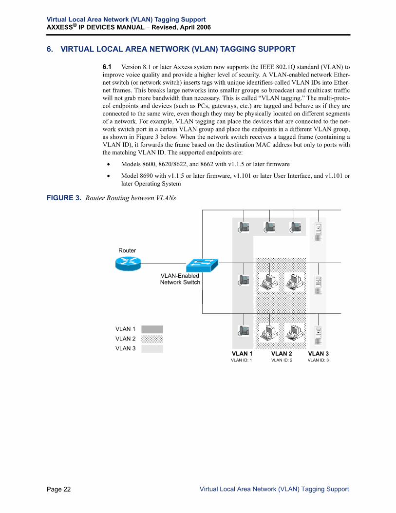
6.1 Version 8.1 or later Axxess system now supports the IEEE 802.1Q standard (VLAN) toimprove voice quality and provide a higher level of security. A VLAN-enabled network Ether-net switch (or network switch) inserts tags with unique identifiers called VLAN IDs into Ether-net frames. This breaks large networks into smaller groups so broadcast and multicast trafficwill not grab more bandwidth than necessary. This is called “VLAN tagging.” The multi-proto-col endpoints and devices (such as PCs, gateways, etc.) are tagged and behave as if they areconnected to the same wire, even though they may be physically located on different segmentsof a network. For example, VLAN tagging can place the devices that are connected to the net-work switch port in a certain VLAN group and place the endpoints in a different VLAN group,as shown in Figure 3 below. When the network switch receives a tagged frame (containing aVLAN ID), it forwards the frame based on the destination MAC address but only to ports withthe matching VLAN ID. The supported endpoints are:
• Models 8600, 8620/8622, and 8662 with v1.1.5 or later firmware
• Model 8690 with v1.1.5 or later firmware, v1.101 or later User Interface, and v1.101 orlater Operating System
FIGURE 3. Router Routing between VLANs
Router
VLAN-Enabled
VLAN 1 VLAN 2 VLAN 3
VLAN 1
VLAN 2
VLAN 3
VLAN ID: 1 VLAN ID: 2 VLAN ID: 3
Network Switch
Page 22 Virtual Local Area Network (VLAN) Tagging Support

Virtual Local Area Network (VLAN) Tagging SupportAXXESS® IP DEVICES MANUAL – Revised, April 2006
VLAN IDs
6.2 When the VLAN tagging feature is enabled, the internal phone Ethernet switch insertsexplicit VLAN tags in the incoming and outgoing frames to the network switch. Each endpointhas the uplink, downlink, and phone ports. The frame is forwarded from the phone or downlinkport to the uplink port. The numbers of the available ports are shown in the table below. Notethat the Models 8600 and 8620/8622 do not have a downlink port. An example of a commonVLAN configuration is shown on the following page.
FIGURE 4. A Common VLAN Configuration
6.3 Each port, except the uplink port, has an associated VLAN group. The VLAN groupmust be uniquely identified by a VLAN ID (number 1 through 4094). The VLAN IDs formulti-protocol endpoints are generally configured in the network switch by your networkadministrator.
NOTE: The VLAN configuration for the network switch varies depending on the switch beingused. Inter-Tel provides recommended VLAN programming guidelines for various switches. Thisinformation can be found in the Tech Central Knowledge Base Center on the Inter-Tel edGeWeb site at www.inter-tel.com/knowledgebasecenter.
ALSO: The Tech Central Knowledge Base Center provides a storage point for resolved issuesand common questions involving Inter-Tel products. The Knowledge Base Center articles areconstantly being added and updated. Also, Answer IDs are not exclusively assigned to one arti-cle. Because there are several databases, an Answer ID can be assigned to several articles;therefore, make sure you are in the Knowledge Base for which you want the appropriate infor-mation.
MODEL UPLINK PORT(LAN/POWER)
DOWNLINK PORT (PC) PHONE PORT
8600/8620/8622 1 0 1
8662 1 1 1
8690 1 3 1
VLAN-Enabled
Uplink (LAN/POWER) PortDownlink (PC) Port
VLAN ID: 16
Multi-Protocol Endpoint
PCInternal Phone
VLAN ID: 8
VLAN Frames VLAN Frames
(Downlink Device)Ethernet Switch
NOTE: The internal phone Ethernet switch and phone port are located inside the endpointand cannot be seen from the outside.
Ethernet Switch
andPhone Port
Network
Page 23VLAN IDs

Virtual Local Area Network (VLAN) Tagging SupportAXXESS® IP DEVICES MANUAL – Revised, April 2006
6.4 To use the VLAN Tagging feature, you must first obtain the VLAN ID informationfrom your network administrator and program the IDs in the endpoints using one of the follow-ing methods:
• Self-programming mode — for Models 8620/8622 and 8662 only (see page 144)
• Web interface (see page 154)
• Configuration files via TFTP server (see page 161)
NOTE: Do not use the configuration file to program the VLAN IDs for the Model 8690.The configuration file update does not overwrite Windows CE’s configuration, therefore,the changes will not be applied to the 8690. To program the 8690, use the 8690 ClientApplication.
• 8690 Client Application — for the Model 8690 only (see page 174)
NOTE: The Model 8690 can be programmed with up to three different VLAN groups because ithas three downlink ports. This does not apply to the Model 8662 endpoint because this endpointhas only one downlink port and each downlink port can only be programmed with one VLANwith a unique VLAN ID.
ALSO: The VLAN Tagging feature does not require any Axxess Call Processing and DatabaseProgramming changes.
6.5 When the network switch receives an untagged frame (that is, does not contain a VLANID) from a port, it forwards the frame to the appropriate port based on the destination MediaAccess Control (MAC) address. If it receives a tagged frame (that is, contains a VLAN ID), itstill forwards the frame based on the destination MAC address but only to ports with thematching VLAN ID. By default, VLAN IDs for the phone and downlink ports are set to zero.
6.6 By programming the VLAN ID differently for the endpoints and downlink devices, theinternal phone Ethernet switch implicitly places the endpoints and downlink devices in differ-ent VLAN groups. As a result, the broadcast frames from the downlink device will not betransferred to the port that is in a different VLAN group. This also applies to the networkswitch because the network switch assigns the frames in the VLAN group based on the VLANtags, which contains the VLAN ID. The network switch is normally connected to the uplinkport. In a common configuration, the phone port is programmed with a VLAN ID other thanzero and the downlink port with zero as the VLAN ID.
6.7 On the other hand, the endpoint and the downlink devices can be in the same VLANgroup but different from the network’s default VLAN that is programmed in the networkswitch. This is done by programming the same VLAN ID in the phone and downlink ports.
Page 24 A Common VLAN Configuration

Virtual Local Area Network (VLAN) Tagging SupportAXXESS® IP DEVICES MANUAL – Revised, April 2006
LAN QoS for VLAN Tagging
6.8 When the endpoint is connected to a network switch that supports 802.1Q, it is stronglyrecommended that you enable LAN QoS to prioritize the Ethernet frames from the endpoint.LAN QoS is a MAC-level QoS. It involves the entire LAN, not just the internal phone Ethernetswitch. When enabled, the pre-defined priority levels of the frame (the Diffserv value of “46”and the 802.1P priority level of “5”) are added to the 802.1Q (VLAN) tag and transferred fromswitch to switch. It is disabled by default.
6.9 The LAN QoS can be enabled using one of the following methods (the LAN QoS set-ting will take effect immediately):
• Web interface (see page 154)
• Configuration files via TFTP server (see page 161)
• Axxess Database Programming — Because the 802.1P priority levels are determined bythe Diffserv value, DB Programming can change the priority levels by changing theRTP TOS bits (set to 184) in DB Programming (under System\Devices and FeatureCodes\IP Connections\<P6xxx>\Audio RTP Type of Service). However, DB Program-ming cannot enable or disable the LAN QoS feature.
Page 25LAN QoS for VLAN Tagging

Quick Start Installation OutlineAXXESS® IP DEVICES MANUAL – Revised, April 2006
7. QUICK START INSTALLATION OUTLINE
7.1 To install the IPRC and IP devices:
1. Install the IPRC in the equipment cabinet. (See page 27.)
2. Update firmware onto the IPRC. (See page 58.)
3. Program the IPRC and its ports in the database. (See page 30.)
4. Set up the IP addressing for the IPRC through the RS-232 port. Program the default IPaddress, default subnet mask, and default gateway address. (See page 130.)
NOTE: For information on network configurations, subnets, and firewalls, seepage 175.
5. With a v1.5.x firmware IPRC, connect the IPRC to the LAN and program the IPRC andIP devices using a Web browser or Telnet interface. (See page 84 for Web instructionsor page 131 for Telnet instructions.) The Web browser is the recommended method, asit is the easiest to use. You will need a PC on the same network as the IP card and itmust have Internet Explorer or Netscape installed.
• Place the devices in “Learn Mode.” (See page 81.) When an IP device powers up itwill broadcast a request on the LAN asking for a connection. The IPRC willrespond and send the information programmed for that device to the IP device.
• You can program the IP device through the dialpad on your IP device. It is called“Self-Programming Mode.” This allows you to program a static IP address, defaultsubnet mask, default gateway address, remote IPRC IP address, remote UDP port,hostname, and control (Bootstrap Protocol) and Dynamic Host Configuration Pro-tocol (DHCP). See page 82 for more information.
NOTE: Although you can program the database of the IP device directly, it ishighly recommended that you change the device-specific settings through theIPRC database only. Once the device connects to the IPRC, the IPRC will repro-gram the device’s local database with the information that is currently stored on theIP card. Therefore, if you make changes to the database of the IP device directly,those changes will be overwritten once the device connects to the IP card.
With a v8.2.x firmware IPRC, connect the IPRC to the LAN and program the IPRC inthe Axxess Database Programming. Program IP devices using one of the methodslisted below. For details, see page 141.
• Self-Programming Mode (Models 8620/8622 and 8662 Only)
• IP Phone Web Client
• TFTP Configuration Files
• Axxess Database Programming for IP Endpoints that are in ITP mode
• Setup Wizard (Model 8690 Only)
6. Update the firmware for the IP devices, if necessary. (See page 58.)
7. Install the IP device(s). (See pages 32 through 56.)
8. If you are installing an MGCP gateway (AudioCodes MP-100 or MP-104) for IP localloop, see page 175.
Page 26 Quick Start Installation Outline

Installing the IPRCAXXESS® IP DEVICES MANUAL – Revised, April 2006
8. INSTALLING THE IPRC
NOTE: This section describes how to install a device IPRC (v1.5.x firmware). For 32-deviceIPRC (v8.2.x firmware) installation instructions, refer to the Addendum to the Axxess v8.0 Instal-lation and Maintenance Manual. For networking IPRC installation instructions, refer to the latestversion of the Axxess Installation and Maintenance Manual.
8.1 The device IPRC accepts connections from all previous versions of hard and soft IPendpoints. It also accepts a database upload that had been saved from a previous IP card. Theextra fields that did not exist on the previous IP card, namely the second set of eight ports, willbe defaulted. A database saved from an IPRC cannot be downloaded to a previous IP card.
8.2 Software on the IPRC does not accept a download containing the code meant for theIPCs. The IPRC will not erase the flash and attempt to program the flash with this erroneouscode; instead, it will send back an error message over RS-232 and Trivial File Transfer Proto-col (TFTP), if used.
NOTE: While flashing an IPRC, the Voice Processor may generate a communication error in itsmessage log (e.g., 208 Alarm). In this case, the 208 alarm indicates that the Voice Processorcannot refresh lamps on extensions that are unavailable while the IPRC is being flashed.Although some lamp refreshes may be delayed until the next refresh cycle, this does not other-wise affect the operation of the Voice Processor.
8.3 The device IPRC is equipped with the following resources:
• Light-Emitting Diode (LED) Indicators: Each card has seven LEDs:
— Card On-Line: Indicates that the card is online.
— Circuit Busy: Indicates that at least one of the Voice over IP (Digital Signal Pro-cessor - DSP) channels is busy.
— Make-Busy Indicator: Shows the current state of the Make-Busy switch. It simplyremains lit while the button is pressed, but does not change the state of the ports onthe card.
— Halted: Indicates that the card is not functioning due to a hardware or softwareerror.
— Full-Duplex Indicator: Indicates that the network connection is running in full-duplex mode.
— Collision: Indicates that the network connection has experienced a collision whilein half-duplex mode.
— 100Base-T Indicator: Indicates that the network connection is operating at a speedof 100 Mbps (Megabits per second).
• Make-Busy Switch: Reserved for future use.
• Two RS-232 Ports: Allow you to program the card’s database, perform diagnostics onthe card, or upload new firmware. (To upload firmware to an IPRC, see page 58.)
• RJ-45 10/100Base-T LAN Connection Port: Provides a connection to either a 10Mbps 10Base-T LAN or a 100 Mbps 100Base-T LAN. This port includes the followingLEDs:
— Link Status LED: When the network connection is valid, the green LED on theleft side of the port is lit.
Page 27Installing the IPRC

Installing the IPRCAXXESS® IP DEVICES MANUAL – Revised, April 2006
— Transmit LED: When the card transmits data to the network connection, the greenLED on the right side of the port is lit.
• DSPs: The IPRC includes up to eight DSPs to encode and decode data for transmissionon IP networks. Each DSP provides up to two, 2-way audio connections.
FIGURE 5. IP Resource Card (IPRC)
MAKE-BUSY SWITCH
RS-232-C JACK (1)
RJ-45 CONNECTOR (LAN)
LINK STATUS LED INDICATORSLNK (GREEN)XMT (GREEN)
CARD ON-LINE (GREEN)CIRCUIT BUSY (YELLOW)MAKE BUSY (YELLOW)HALTED (RED)
NOTE: For purposes of detail,this drawing does not show theEMI shield attached to thefront edge of the card.
DUPLEX (GREEN)COLLISION (YELLOW)100BASE-T (GREEN)
LED INDICATORS
LED INDICATORS
RS-232-C JACK (2)
U22
PAL
Page 28 IP Resource Card (IPRC)

Installing the IPRCAXXESS® IP DEVICES MANUAL – Revised, April 2006
Installing the IPRC
8.4 To install the IPRC:
1. Verify that all components on the cards are seated securely in their sockets and that nopins are bent. See page 28 for an illustration of the IPRC.
2. Insert the IPRC in its appropriate slot in the cabinet. (The slot must be programmed fora DKSC16.) The component sides of the card must face right.
NOTE: The IPRC might halt (red Halt LED remains lit) on hot-card insertion. If so, waitabout 4-5 seconds for the CPU card to bring the card out of the halted state, rather thanattempt to reseat the IPRC.
3. Connect one end of the Ethernet cable to the RJ-45 connector labeled “LAN” on theIPRC. Connect the other end of the cable to the RJ-45 connector on the LAN or net-work hub.
NOTE: Do not connect the IPRC to the LAN until the IPRC is programmed. Some hubshave a straight-through/crossover switch. The switch must be selected for straight-through operation.
4. Upload firmware to the IPRC using the Upload Utility (previously called the BoardUtility) or the TFTP Download program. The IPRC firmware is not automaticallyupdated by Call Processing. The Upload Utility supports an RS-232 method as well as anetwork connection for uploading the firmware onto the IPRC. See page 58 for moredetails.
5. Configure all IPRC settings using the Database Programming interface (see page 30).An IPRC includes Web-based and telnet configuration interfaces.
6. For hard IP endpoints installation see page 32, and for SIP endpoints installation seepage 56.
NOTE: The programming of individual ports remains the same: IP PhonePlus, Model8660 endpoint, or IP softphone must be on a phone port, and the IP SLA must be ondual-SLA, even though only the first single line device is used.
Upgrading the PAL
8.5 You can upgrade an 8-port PAL with the 16-port PAL. To upgrade the PAL, order the16-port station PAL (part no. 827.9450) and upgrade fee (part no. 828.1637).
NOTE: Axxess v8.2.x uses the software licenses instead of PALs to determine the card func-tionality. Refer to the Addendum to the Axxess v8.0 Installation and Maintenance Manual fordetails.
CAUTION
The cards and the software components are static-sensitive. Handle the cards by the edgesonly and keep the components in their protective case until they are ready to be installed.Do not bend or touch the pins of the components or subject them to a static charge. Whenworking with the cards, use a properly terminated anti-static wrist strap. Any static charge(no matter how small the charge) must be discharged from the body before touching thecards or components. The warranty for this equipment does not cover damage caused bystatic or mishandling. Cards or components damaged in such a manner will not be replaced.
Page 29Installing the IPRC

System Database ProgrammingAXXESS® IP DEVICES MANUAL – Revised, April 2006
9. SYSTEM DATABASE PROGRAMMING
NOTE: This section describes how to program device IPRCs (v1.5.x firmware) on AxxessDatabase programming. For 32-device IPRC (v8.2.x firmware) programming instructions, referto the Addendum to the Axxess v8.0 Installation and Maintenance Manual. For NetworkingIPRC programming instructions, refer to the latest version of the Axxess Installation and Mainte-nance Manual.
9.1 Make sure you are using Inter-Tel system version 3.0 or later. The slot in the cabinetthat will be used by the IPRC must be programmed as a DKSC-16.
NOTE: The “Amps Required” field will show that the card requires the 0.64 amps needed by aDKSC-16. However, an IPRC only requires 0.34 amps.
9.2 Program the port as Keyset if an IP endpoint, such as the IP PhonePlus, IP softphone,will be connected. Program the port as Dual Single-Line for an IP SLA (even though the IPSLA supports only one single-line endpoint).
9.3 To program an Loop Start Adapter (LSA) for IP local loop, see page 177.
NOTE: When configuring a SIP endpoint via Database Programming, the endpoint station flag“Handsfree Mode on/off” must be set to “no” (under System\Devices and Feature Codes\sta-tions\<extension>\Flags).
Programming an Emergency Extension for IP Devices
9.4 The following is the recommended programming for a system that has remote loop ter-mination with the need for emergency access for the remote IP endpoints.
1. Create a Trunk Group that contains the LSAs programmed in the DKSC-16.
2. Program this Trunk Group as the Emergency Extension for the remote IP endpoints thatwill use the LSAs for local loop access.
3. When programming the Emergency Outgoing Access for the Trunk Group containingthe LSAs, give the remote IP endpoints outgoing access, but remove all other stationsand extension lists.
4. Program the Local Trunk Group as the Emergency Extension for local endpoints.
5. When programming the Emergency Outgoing Access for the Local Trunk Group,include all local endpoints, but not the remote IP endpoints.
6. Create a facility group that contains the Local Trunk Group first, followed by the TrunkGroup for the IP endpoints.
7. Program this facility group in Route Group 1.
8. Program the Emergency Outgoing Access for all node trunk groups to include nodevices. Each node should have local trunk termination because emergency outgoingaccess across nodes is not warranted.
Page 30 System Database Programming

System Database ProgrammingAXXESS® IP DEVICES MANUAL – Revised, April 2006
NOTE: If an installation needs Emergency Outgoing Access across nodes, make sure theLocal Trunk Group is the first member in the facility group. This allows cross-node emergencycalls to use the Local Trunk Group first and not the Remote IP Trunk Group.
NOTICEIt shall be the responsibility of the entity or person(s) completing installation and mainte-nance of hardware or software described herein to research, comply with and be responsi-ble for the specific governmental rules and regulations regarding Emergency OutgoingAccess (911) of the geographic location in which such functions are performed.
Page 31System Database Programming

Installing the IP and Multi-Protocol EndpointsAXXESS® IP DEVICES MANUAL – Revised, April 2006
10. INSTALLING THE IP AND MULTI-PROTOCOL ENDPOINTS
10.1 The installation of an IP or SIP endpoint is very simple. The device is connected to apower source and to the network. There is no direct wiring from the IP card to the endpoint.The available IP/SIP endpoints are the Axxess/Eclipse2 IP PhonePlus with a 10Base-T LANhub, the Model 8660 endpoint, and Model 8600 series multi-protocol endpoints.
A. PHYSICAL INTERFACES
10.2 The following pages describe information about available features on each IP endpointwith illustration of the physical interface.
CAUTION
Inter-Tel strongly recommends using the IP devices on a managed private network. Ifconnected to the public Internet, IP devices will function, but the quality may suffer due tothe dynamic bandwidth availability. The possible problems could be voice quality degrada-tion, garbled speech, dropped calls, equipment resets, etc. Also, the VoIP suitability of anyInternet connection can change at any time, with no advance notice. Inter-Tel cannotguarantee any voice quality when connected to the public Internet. Therefore, Inter-Tel is not responsible for network quality issues that are caused by using the publicInternet. For recommended guidelines on IP network specifications, see page 6.
NOTICEThe IP softphone requires v1.5.x firmware and does not support IPRCs that have v8.2.xfirmware. Other IP endpoints, such as the Model 8660 Phone, however, require the new (orupgraded) 8.1 or later firmware IPRCs to support the new features. For these reasons, Inter-Tel recommends that you do not connect IP softphones and other IP endpoints to the sameIPRC. If you do, you may lose feature or endpoint functionality. See page 5 for the com-plete IPRC firmware matrix.
Page 32 Installing the IP and Multi-Protocol Endpoints

Installing the IP and Multi-Protocol EndpointsAXXESS® IP DEVICES MANUAL – Revised, April 2006
Axxess IP PhonePlus
10.3 Axxess IP PhonePlus with 10Base-T hub supports 10Base-T LANs. See below for adiagram of the 10Base-T hub.
10.4 The Axxess IP PhonePlus includes the following features:
• Speaker: Used for ring, group listen, speakerphone, and page.• LCD: Supports six lines of display with 16 characters per line.• Handsfree Microphone: Is a built-in microphone.• LAN/POWER Jack: Connects to an external power supply or a network hub/switch.• POWER Jack: Connects to a 24VDC external power supply.
NOTE: Use only one power source to connect the power supply.
• OUT TO PC Jack: Connects to a PC.• LEDs: There are two indications on each port:
— Link Status: When the link is valid, the green LED on the left side of the port islit. When there is receive or transmit activity on the link, the LED flashes.
— Collision: When there are both receive and transmit activities on the link, the yel-low LED on the right side of the port is lit.
10.5 For information about programming an Axxess IP PhonePlus, see page 80.
LAN/POWER OUT TO PCPOWER
LEDs
SPEAKER(Underneath Handset)
Front
Bottom
HANDSFREE MICROPHONE(Underneath Edge)
6x16 LCD
∞
Page 33Axxess IP PhonePlus

Installing the IP and Multi-Protocol EndpointsAXXESS® IP DEVICES MANUAL – Revised, April 2006
Eclipse IP PhonePlus
10.6 Eclipse IP PhonePlus with 10base-T hub supports 10Base-T LANs. See below for dia-grams of the 10Base-T hub.
10.7 The Eclipse IP PhonePlus contains the following features:• Speaker: Used for ring, group listen, page, and speakerphone features.• LCD: Supports six lines of display with 16 characters per line.• Handsfree Microphone: Is a built-in microphone.• Message Indicator: Flashes when there is a voice mail or station message for the
phone.• LAN/POWER Jack: Connects to an external power supply or a network hub/switch.• Barrel Jack: Connects to an external power supply.• Ports 1-3 (OUT TO PC Jack): Connects up to three other IP devices, such as PCs,
notebooks, and printers.• LEDs: There are two indications on each port.
— Link Status: When the link is valid, the green LED on the left side of the port islit. When there is receive or transmit activity on the link, the LED flashes.
— Collision: When there are both receive and transmit activities on the link, the yel-low LED on the right side of the port is lit.
• Handset Jack: Connects to a handset.• LCD Contrast Knob: Adjusts contrast of the LCD display.
10.8 For information about programming an Eclipse IP PhonePlus, see page 80.
DC BARREL JACK
HANDSET JACKLCD CONTRAST KNOB
The center is positive.
PORT 3(DC: Direct Current)
LAN/POWER
PORT 1PORT 2
BottomLEDs
Front
Back
MESSAGE
SPEAKER
6x16 LCD
HANDSFREEMICROPHONE
(underneath edge)
INDICATOR
Page 34 Eclipse IP PhonePlus

Installing the IP and Multi-Protocol EndpointsAXXESS® IP DEVICES MANUAL – Revised, April 2006
Model 8660
10.9 Model 8660 endpoint supports both 10Base-T and 100Base-TX interfaces, but not100Base-T4 (using four pairs of wires). See below for diagrams of the endpoint.
10.10 The Model 8660 includes the following features:
• Speaker: Used for ring, group listen, page, and speakerphone features.
• LCD: Supports six lines of display with 16 characters per line.
• Handsfree Microphone: Is a built-in microphone.
• Message Indicator: Flashes when there is a voice mail or station message for thephone.
• LAN/POWER Jack: Connects to a network hub or a switch and gets power from pins7 and 8.
• POWER Jack: Connects to a 24VDC external power supply.
NOTE: Use only one power source to connect the power supply.
• PC 1-3 Ports: Connect to PCs or any other 10/100 Ethernet devices. The speeds on sin-gle uplink and three downlink ports are independent from each other and auto-negotia-ble.
• Handset Jack: Connects to a handset.
• Headset Jack: Connects to a headset.
• LEDs: There are two indications on each port:
— Link Status: When the link is valid, the green LED on the left side of the port islit. When there is receive or transmit activity on the link, this LED flashes.
— 10/100 Mbps: When the link is connected at a speed of 100 Mbps, the green LEDon the right side of the port is lit.
10.11 For information about programming a Model 8660, see page 80.
24VDC POWER
PC 3 PC 2
LEDs
(Downlink RJ-45)
Front Back
HEADSET JACK HANDSET JACK
PC 1
MESSAGE INDICATOR
SPEAKER
6x16 LCD
HANDSFREE MICROPHONE(Underneath Edge)
(Underneath Handset)
Page 35Model 8660

Installing the IP and Multi-Protocol EndpointsAXXESS® IP DEVICES MANUAL – Revised, April 2006
Models 8600, 8620/8622, and 8662
10.12 Models 8600, 8620/8622, and 8662 multi-protocol endpoints operate like Models 8500,8520, and 8560 endpoints, respectively. These endpoints support ITP (an Inter-Tel protocol) orSIP mode using 100Base-TX interfaces. See below for diagrams of the endpoints. All end-points are configured to use ITP by default. For details about ITP and SIP modes, see page 53.
HEADSET/HANDSET
LAN/POWER
LEDs
(Uplink RJ-45)
Front Back
Model 8600
MESSAGE INDICATOR
JACKSPEAKER
(Underneath Handset)
Front Back
HEADSET JACK HANDSET JACK
LAN/POWER(Uplink RJ-45)
LEDs
Model 8620
MESSAGE INDICATOR2x16 LCD
HANDSFREEMICROPHONE
(Underneath Edge)
SPEAKER(Underneath Handset)
Not Used
Page 36 Models 8600, 8620/8622, and 8662

Installing the IP and Multi-Protocol EndpointsAXXESS® IP DEVICES MANUAL – Revised, April 2006
10.13 The Model 8600 series endpoints include the following features:
• Speaker: Used for ring, group listen, page, and speakerphone features.
• LCD: (Models 8620/8622 and 8662 only) Supports two/six lines of display with 16characters per line.
• Message Indicator: Flashes when there is a voice mail or station message for the end-point.
• Headset/Handset Jack: Connects to a headset or handset.
• Handsfree Microphone: (Models 8620/8622 and 8662 only) Is a built-in microphone.
Front BackModel 8622
MESSAGE INDICATOR2x16 LCD
HANDSFREEMICROPHONE
(Underneath Edge)
SPEAKER(Underneath Handset)
HEADSET JACK HANDSET JACK
LAN/POWER(Uplink RJ-45)
PC(Downlink RJ-45)
LEDs
Front BackHEADSET JACK HANDSET JACK
LAN/POWER(Uplink RJ-45)
PC(Downlink RJ-45)
LEDs
Model 8662
MESSAGE INDICATOR6x16 LCD
HANDSFREEMICROPHONE
(Underneath Edge)
SPEAKER(Underneath Handset)
MESSAGE INDICATOR
Page 37Models 8600, 8620/8622, and 8662

Installing the IP and Multi-Protocol EndpointsAXXESS® IP DEVICES MANUAL – Revised, April 2006
• LAN/POWER Jack: Connects to an external power supply or a network hub/switch.• PC Port: (Models 8622 and 8662 only) Connects to a PC or any other 10/100 Ethernet
device. The speeds on single uplink and downlink port are independent from each otherand auto-negotiable.
• LEDs: There are two indications on each port:
— Link Status: When the link is valid, the green LED on the left side of the port islit. When there is receive or transmit activity on the link, this LED flashes.
— 10/100 Mbps: When the link is connected at a speed of 100 Mbps, the green LEDon the right side of the port is lit.
• DRAM: Located inside the endpoints. Models 8600, 8620, and 8662 (part no.550.8662) support 8 MB, and Models 8622 and 8662 (part no. 550.8662E) support 16MB (only one slot is occupied).
NOTE: Although there are two DRAM slots, you cannot upgrade the memory by add-ing an extra memory stick. Currently, the second slot is not used.
10.14 For information about programming Model 8600 series endpoints, see page 141.
Page 38 Models 8600, 8620/8622, and 8662

Installing the IP and Multi-Protocol EndpointsAXXESS® IP DEVICES MANUAL – Revised, April 2006
Model 8690
10.15 The Model 8690 multi-protocol endpoint has a touch screen that displays feature, dial-pad, and menu buttons. It supports ITP or SIP mode using 100Base-TX interfaces. The Model8690 endpoint is configured to use ITP by default. For details about ITP and SIP modes, seepage 53.
10.16 The Model 8690 includes the following features:
• Speakers: Used for ring, group listen, page, and speakerphone features — supportsmono for IP endpoint and stereo for Windows CE playback.
• LCD: Supports active matrix color LCD.
• Message Indicator: Flashes when there is a voice mail or station message for the end-point.
• LAN/POWER Jack: Connects to an external power supply or a network hub/switch.
• PC Ports 1-3: Connect to PCs or any other 10/100 Ethernet devices. The speeds on thesingle uplink and three downlink ports are independent from each other and auto-nego-tiable.
• Handsfree Microphone: Supports high fidelity.
• Headset/Handset Jack: Connects to a headset or handset.
• SPKR Jack: Connects to a speaker — supports mono for IP endpoint and stereo forWindows CE playback.
• MIC Jack: Connects to a microphone (3.5 mm connector).
• Reset Button: Resets the endpoint (press and release the Reset button quickly).
NOTE: If you press and hold the Reset button until the four LEDs on the front of theendpoint (Message Lamp) start blinking, the system defaults the endpoint configuration(such as the configuration TFTP URL).
• CF (Compact Flash) Port: Connects to a compact flash memory card that can be usedfor copying music, pictures, etc. to the Model 8690. It also can be used as additionalmemory.
LAN/POWER
LEDs
(Uplink RJ-45)
Front Back
PCs 1, 2, and 3 (Downlink RJ-45)
PCMCIA
USB HOST
USB CLIENT CF
MIC SPKR
ACTIVE MATRIX COLOR LCD
SPEAKERS
RESET BUTTON
HANDSFREE MICROPHONE
HEADSETJACK*
HANDSETJACK*
*The headset and handset jacks are located on the base.
MESSAGE INDICATOR
Page 39Model 8690

Installing the IP and Multi-Protocol EndpointsAXXESS® IP DEVICES MANUAL – Revised, April 2006
• PCMCIA (Personal Computer Memory Card International Association) Port:Connects to a memory card if additional memory is needed.
• USB (Universal Serial Bus) HOST Port: Connects to a standard USB keyboard,mouse, etc.
NOTE: For details about how to connect a keyboard and/or mouse, refer to the Model8690 User Guide.
• USB CLIENT Port: Connects to a host computer that runs Microsoft ActiveSync®.
• LEDs: There are two indications on each port:
— Link Status: When the link is valid, the green LED on the left side of the port islit. When there is receive or transmit activity on the link, this LED flashes.
— 10/100 Mbps: When the link is connected at a speed of 100 Mbps, the green LEDon the right side of the port is lit.
• DRAM: Located inside the endpoint. Supports 128 MB (only one slot is occupied).
NOTE: Although there are two DRAM slots, you cannot upgrade the memory by add-ing an extra memory stick. Currently, the second slot is not used.
10.17 For information about how to program a Model 8690, see page 141.
10.18 To use the Model 8690, you must first install the 8690 client application. See page 168for details.
Page 40 Model 8690

Installing the IP and Multi-Protocol EndpointsAXXESS® IP DEVICES MANUAL – Revised, April 2006
B. INSTALLATION
10.19 Install the endpoints as follows.
NOTE: For IP SLA installation instructions, see page 56.
1. Ensure that the IPRC is connected to the LAN and the On-Line LED is lit.
NOTE: Some hub or switch ports have a straight-through/crossover switch. The switchmust be selected for straight-through operation.
2. Attach the coiled handset cord to the handset and to the handset jack on the reverse ofthe endpoint. Place the handset on hook. If wall mounting the endpoint, refer to theinstructions on page 44.
NOTE: If you are installing an Axxess/Eclipse IP PhonePlus with a 10Base-T LAN hub,skip to step 4.
3. Remove the metal plate from the base ofthe endpoint as follows:
a Remove the two plastic rivets tounlock it from the base.
b Slide the cover off.
The two plastic rivets are not included onendpoints built prior to May 2005.
4. Connect one end of the Ethernet cable to a PC port on the back of the endpoint. Con-nect the other end of the cable to the PC.
NOTE: For Model 8660, use unbooted Ethernet cables. The Model 8660 does not sup-port booted cables because the plastic “protective” ends on booted Ethernet cables getin the way when routing the cable away from the endpoint.
WARNINGDo not connect the PC ports to each other or to a hub. Doing so may cause adversenetwork conditions. Also, Inter-Tel does not recommend connecting additional hardIP endpoints to the PC ports. Due to the QoS (Quality of Service) present on thesehard IP endpoints, the IP endpoints located behind an IP endpoint will have a lowerpriority when sending data upstream to the network. Under heavy network condi-tions, voice quality may be reduced.
Plastic Rivet
Base
Page 41Installation

Installing the IP and Multi-Protocol EndpointsAXXESS® IP DEVICES MANUAL – Revised, April 2006
5. Connect the power supply, using one of the following methods. Depending on the IPdevices to be used, there are several power supplies available. Refer to page 43 for thematrix that lists the compatibilities of power supplies.
• US/UK/Universal Power Supply using a LAN Jack: Using the CAT5 cable, connectthe LAN/POWER jack on the baseplate to the KS/SLA jack on the 24VDC adapter.Then using another cable, connect the LAN jack on the 24VDC adapter to theLAN. Connect the 24VDC adapter to a 110V wall socket.
Inter-Tel currently offers the following power supply kits.
* Requires a standard IEC (International Electrical Cord) power connector.
• Universal Power Supply using a Barrel Jack: Using the CAT5 cable, connect theLAN/POWER jack on the baseplate directly into the network. Do not connect thiscable to the PC 1, PC 2, or PC 3 jack. Connect the adapter to an AC voltage powersource and connect the barrel plug on the power adapter to the barrel jack on thebaseplate (if available). The center of the barrel jack is positive. The minimumpower requirements for the IP device is 24VDC at 500mA (using a Universalpower supply) and 24VDC at 400mA (using a customer-provided power supply).
• Power over Ethernet (PoE) hub (LAN Jack): The Red Hawk PowerSense™ modu-lar in-line PoE hubs (for multi-port) are available through the Inter-Tel Com-mSource® division. The power hub provides power to IP devices without the use ofan external power supply for each device. Using the CAT5 cable, connect the LAN/POWER (RJ-45) jack on the IP device directly into the POWER/DATA (RJ-45)jack on the PoE connector. For details, see the Red Hawk PowerSense Power overEthernet Installation Manual.
PART NUMBER CONTAINS:
828.1642 - US power supply (P/N 806.1113)- Network cable (P/N 813.1790)
828.1660 - Universal power supply (P/N 806.1119)*- Network cable (P/N 813.1790)
NOTICETo reduce the effects of AC voltage surges and spikes that may cause damage to theelectronic components, a surge/spike protector with the following specifications isrecommended:• Clamp voltage transients at 300VAC within 5 nanoseconds when exposed
to waveforms as described in the ANSI/IEEE Standard C62.41-1980 (IEEE 587).
• RFI/EMI noise reduction by at least 20dB at frequencies between 5kHz and 30MHz.
Inter-Tel’s CommSource division sells a surge/spike protector (part number900.0500) that has all of these specifications.
CAUTION
Only use a single, appropriate power adapter with the IP device. Do not connect aUS power supply and a Universal power supply to the same IP device. Also, whenusing the Universal Power Supply with a barrel connector, no devices (e.g., hubs)should be inserted between the KS/SLA jack on the adapter and the LAN jack onthe IP endpoint because power is supplied through the cable.
Page 42 Installation

Installing the IP and Multi-Protocol EndpointsAXXESS® IP DEVICES MANUAL – Revised, April 2006
6. To hide the cables, route the Ethernet and power supply cables in the baseplate, in away where you can replace the metal plate.
7. Re-attach the metal plate to the base.8. Insert the two plastic rivets, if applicable, through the metal plate and press them firmly
into the holes to lock the metal plate to the base.9. While the endpoint is connecting to the IPRC, the display shows information about its
connection state, including its Ethernet address, IP address, subnet mask, gatewayaddress, and the address of the IP card to which it is connecting. The display thenshows the station identification (port number, extension number, and assigned user-name) for several seconds. Then, the LCD changes to the appropriate display, depend-ing on its current status. (See the chart on page 49 for an explanation of status displays.)
NOTE: If the endpoint appears to be stuck in “Waiting For Download” mode, try to pingits IP address. If you cannot ping the device, assign a valid BOOTP IP address from aBOOTP server (usually your IP card*) to the device’s Ethernet address. Also, changethe default IP address, subnet mask, and default gateway so that the device receives abetter default when it reconnects to the IPRC after the download. When waiting for adownload, the IP device will attempt BOOTP, even if BOOTP is disabled in IPRC pro-gramming. Cycle the power on the IP device and then download the software.
*The IPRC v8.2.x firmware does not provide a BOOTP server and requires a static IP address orthe use of either a third-party BOOTP sever or a DHCP server for IP address assignment.
C. POWER SUPPLY COMPATIBILITIES10.20 Refer to the IP Device Power Supply Compatibility Matrix (document part no.835.2688) for the matrix of available power supplies.
Page 43Installation

Installing the IP and Multi-Protocol EndpointsAXXESS® IP DEVICES MANUAL – Revised, April 2006
D. WALL MOUNTING
Axxess IP PhonePlus
10.21 To wall mount the Axxess IP PhonePlus:
1. Remove the endpoint baseplate from the top half of the back of the endpoint.
2. Carefully unplug the ribbon cable.
3. On the back of the endpoint, use a pair ofcutting pliers to remove the plastic knockoutcovering the lower connector on the endpointcontrol board.
NOTE: Be careful not to let the plasticknockout fall inside the endpoint. If thisoccurs, do not remove the plastic knockout.
4. Plug the free end of the ribbon cable into theconnector on the endpoint control board(where the plastic knockout was previouslyremoved).
NOTE: Use a pencil (eraser end) or othersuitable rod-like instrument to press eachend of the cable into the connector. Applypressure until the connector clicks securelyinto place, one end at a time.
5. Rotate the baseplate 180º and attach it to the bottom half of the back of the endpoint.
6. Using a ruler, mark the location of the endpoint mounting holes on the wall. (The cen-ters of the two perpendicular mounting holes on the back of the endpoint are four inchesapart.)
7. Drive a screw into the center of each mounting hole marking. Allow the head of thescrew to protrude approximately ¼ inch.
8. To hold the handset in place while the end-point is wall-mounted, slide the reversible cra-dle hook out, rotate it 180º, and reinsert it asshown on the right.
9. Position the endpoint mounting holes over thescrews and slide the endpoint into position onthe wall. (If necessary, adjust the screws toensure the endpoint is held firmly in place.)
Remove this knockout toaccess the connector on theendpoint control board.
Remove the ribbon cable from this connector.
BACK OF ENDPOINT
Page 44 Axxess IP PhonePlus

Installing the IP and Multi-Protocol EndpointsAXXESS® IP DEVICES MANUAL – Revised, April 2006
Eclipse IP PhonePlus
10.22 To wall mount the Eclipse IP PhonePlus:
1. Remove the endpoint baseplate from the top half of the back of the endpoint.
2. Rotate the baseplate 180º and attach it to the bottom half of the back of the endpoint.
3. Using a ruler, mark the location of the endpoint mounting holes on the wall. (The cen-ters of the two perpendicular mounting holes on the back of the endpoint are four inchesapart.)
4. Drive a screw into the center of each mounting hole marking. Allow the head of thescrew to protrude approximately ¼ inch.
5. To hold the handset in place while the end-point is wall-mounted, slide the reversible cra-dle hook out, rotate it 180º, and reinsert it asshown on the right.
6. Position the endpoint mounting holes over thescrews and slide the endpoint into position onthe wall. (If necessary, adjust the screws toensure the endpoint is held firmly in place.)
Page 45Eclipse IP PhonePlus

Installing the IP and Multi-Protocol EndpointsAXXESS® IP DEVICES MANUAL – Revised, April 2006
Model 8600 Series Endpoints
NOTE: Wall mounting the Model 8600 series endpoints is not recommended if the user will beconnecting and disconnecting cords (handset, headset, line) and/or cables (Ethernet, USB,power supply) frequently. To connect and disconnect these cords and cables from a wall-mounted endpoint, the user will need to remove the endpoint from the wall.
10.23 Because there are two types of bases used on the Model 8600 series endpoints, two setsof instructions for wall mounting the endpoints are included here. Determine which type ofbase the endpoint has and follow the appropriate instructions.
10.24 For best results when wall mounting the Model 8600 series endpoints, Inter-Telstrongly recommends that you use the two plastic rivets shipped with the endpoint. Onceinstalled, the plastic rivets lock the components into place, providing additional stability forwall-mounted endpoints.
10.25 Model 8600 series endpoints are shipped with a plastic adhesive label that covers therectangular wall-mount knockout on the base of the endpoint. A portion of the adhesive labelmust be removed to use the wall-mount knockout.
10.26 To wall mount the Model 8600 series endpoints, you need an industry-standard wall-mount bracket (sometimes called a wall jack assembly) and a four-inch line cord. Both of theseitems are available through the Inter-Tel CommSource® division.
10.27 To prepare the endpoint for wall mounting (regardless of base type):
1. Remove the metal plate from the base ofthe endpoint as follows:
c Remove the two plastic rivets tounlock it from the base.
d Slide the plate off.
The two plastic rivets are not included onendpoints built prior to May 2005.
2. Use a sharp blade to cut out the rectangularportion of the adhesive label covering thewall-mount knockout.
Plastic Rivet
Base
Wall-Mount Knockout
Page 46 Model 8600 Series Endpoints

Installing the IP and Multi-Protocol EndpointsAXXESS® IP DEVICES MANUAL – Revised, April 2006
10.28 To wall mount the Model 8600 series endpoints that have a support mechanism:
NOTE: The following instructions apply to endpoints that have a support mechanism (see illus-tration below) that fits into holes in the base.
1. Collapse the support mechanism completely and secure it against the bottom housing ofthe endpoint, as shown below.
2. Close the base completely so that it lies flat against the endpoint. (The two rivet holeson the base align with the two rivet holes on the bottom housing of the endpoint.)
3. Plug the four-inch line cord into the jack on the back of the endpoint and thread the linecord through the wall-mount knockout on the base.
4. Insert the two plastic rivets through the base and press them firmly into the holes on thebottom housing of the endpoint. This locks the base to the endpoint.
5. Test the base to verify that it is securely locked to the endpoint.
6. Re-attach the metal plate to the endpoint base.
7. Insert the two plastic rivets, if applicable, through the metal plate and press them firmlyinto the holes on the base of the endpoint. This locks the metal plate to the base.
8. Plug the line cord into the jack on the wall-mount bracket and position the endpointsecurely on the wall-mount bracket.
9. Flip the handset hanger down to the horizontal position and lock it into place. This willhold the handset in place.
Bottom HousingSupport (Base not shown)MechanismBase
Rivet HolesRivet Holes
Page 47Model 8600 Series Endpoints

Installing the IP and Multi-Protocol EndpointsAXXESS® IP DEVICES MANUAL – Revised, April 2006
10.29 To wall mount the Model 8600 series endpoints that have release buttons locatedon the bottom housing:
NOTE: The following instructions apply to endpoints that have release buttons located on thebottom housing of the endpoint. To disengage the locking mechanism in the base, push in bothbuttons. To lock the base in position, release the buttons.
1. Close the base completely so that it lies flat against the endpoint. (Rivet hole 1 on thebase aligns with the rivet hole on the bottom housing of the endpoint.)
2. Plug the four-inch line cord into the jack on the back of the endpoint and thread the linecord through the wall-mount knockout on the base.
3. Insert one of the plastic rivets in rivet hole 1 on the base (see illustration above) andpress it into the rivet hole on the endpoint. This locks the base to the endpoint.
4. Test the base to verify that it is securely locked to the endpoint.
5. Re-attach the metal plate to the endpoint base.
6. Insert the two plastic rivets through the metal plate and press them firmly into the holeson the base of the endpoint. This locks the metal plate to the base.
7. Insert the remaining plastic rivet through rivet hole 3 (asshown at right) in the metal plate and press it firmly intorivet hole 2 in the base. This locks the metal plate to thebase.
8. Plug the line cord into the jack on the wall-mount bracketand position the endpoint securely on the wall-mountbracket.
9. Flip the handset hanger down to the horizontal positionand lock it into place. This will hold the handset in place.
Rivet Hole
Base
Rivet Hole 1
Release Buttons
Bottom Housing (Base not shown)
Rivet Hole 2(Used to lock metal plate to base)
(Used to lock base to bottom housing)
Rivet Hole 3
Metal Plate
Page 48 Model 8600 Series Endpoints

Installing the IP and Multi-Protocol EndpointsAXXESS® IP DEVICES MANUAL – Revised, April 2006
E. IP ENDPOINT STATUS DISPLAYS
10.30 While the boot code is loading, you will see the displays shown below. In the displays,the top lines change, as shown in the chart, and the bottom lines always contain the IP addressand the Ethernet address.
NOTE: Several displays have a “/” character at the end that is a rotating bar to indicate that thedevice is working.
For IP PhonePlus and Model 8660
10.31 For status displays for Models 8620/8622, 8662, and 8690, see page 71.
DISPLAY STATUS
WAITING FOR DOWNLOAD Awaiting Download: The boot code is waiting for a code download.
ERASING FLASH Programming State - Erasing Flash Memory: The boot code is receiving object code and programming the flash memory. The endpoint first erases the flash memory and then displays this message.
PROGRAMMING CODE Programming State - Programming Flash Memory: After erasing the flash, the endpoint programs the flash memory.
DOWNLOAD COMPLETED Completed State: The download completed successfully.
HARDWARE FAILUREFLASH ERASURE
Error State - Flash Erasure: The boot code encoun-tered an error in erasing the flash chips. If this occurs, try two or three downloads before returning the endpoint for repair.
HARDWARE FAILUREFLASH PROGRAM
Error State - Flash Program: The boot code encoun-tered an error while programming the flash chips. If this occurs, try two or three downloads before returning the endpoint for repair.
HARDWARE FAILUREMEMORY MAP
Error State - Memory Map: The hardware memory-map functions are not working properly. After two or three failed attempts, you should send in the endpoint for repair.
DOWNLOAD ABORTEDFILE TOO BIG
Error State - File Too Big: This display appears if you attempt to download a file that is too large for the flash memory. This error condition might indicate an incorrect or corrupted file.
DOWNLOAD ABORTEDFILE CORRUPTED
Error State - File Corrupted: This display appears if you attempt to download a file that is corrupted or that gets corrupted during the transmission. This error condition might occur during poor network conditions.
Page 49IP Endpoint Status Displays

Installing the IP and Multi-Protocol EndpointsAXXESS® IP DEVICES MANUAL – Revised, April 2006
10.32 While the application code is executing, you will see the following displays as it movesthrough several states. After the endpoint is connected to the IP card, the default displayappears on the LCD.
NOTE: Several displays have a “/” character at the end that is a rotating bar to indicate that thedevice is working.
For IP PhonePlus and Model 8660/8620/8622/8662/8690
NOTE: The following information does not apply to a non-LCD endpoint, such as the Model8600. Also, because the Model 8620/8622 has a two-line LCD, this endpoint displays only thefirst two lines of the status.
DISPLAY STATUS
INITIALIZING
TRYING BOOTP...NO RESPONSETRYING DHCP...SUCCESSFUL /
Initializing: The application code is initializing the IP stack. For the majority of the initialization time, the IP endpoint is waiting for a BOOTP or DHCP response. If the IP endpoint receives a BOOTP or DHCP response, the IP endpoint uses the IP address, subnet mask, and gateway address from the response. If the IP endpoint times out, the IP endpoint uses its default IP address, subnet mask, and gateway address from its internal database. For each enabled option (BOOTP, DHCP, or both), an LCD shows a message indicating that the endpoint is attempting to receive that type of response. If at least one of these options is enabled and the endpoint is not able to receive an IP address, it will show “NO RESPONSE” for five seconds. If the endpoint tries BOOTP and fails, but then tries DHCP and succeeds, the display will not pause in order to reduce waiting time.
ID: XXXXXXXXXXXXMY IP ADDRESS:XXX.XXX.XXX.XXXFINDING LOCALIP CARD ON UDPPORT XXXXX /
Finding IP Card Address: The application code is attempting to find a local IP card by broadcasting on the LAN. The first line contains the hexadecimal Ethernet address of the endpoint, while the second and third lines inform the user of the endpoint’s IP address. The rest of the LCD informs the user that the endpoint is attempting to find the IP card and its port number.
ID: XXXXXXXXXXXXMY IP ADDRESS:XXX.XXX.XXX.XXXFINDING IP CARD:XXX.XXX.XXX.XXXUDP PORT XXXXX /
Finding IP Card: The application code is attempting to find a local IP card by using the reply from the LAN broadcast. The first line contains the hexadecimal Ethernet address of the endpoint, while the second and third lines inform the user of the endpoint’s IP address. The rest of the LCD display informs the user that the endpoint is attempting to find the IP card and the IP address and its port number.
ID: XXXXXXXXXXXXMY IP ADDRESS:XXX.XXX.XXX.XXXCONNECTING TO:XXX.XXX.XXX.XXXTCP PORT XXXXX /
Connecting to IP Card: The application code is attempting to connect to an IP card. The first line contains the hexadecimal Ethernet address of the endpoint. The second line contains the IP endpoint’s current IP address. The fourth line contains the IP address to which the IP endpoint is attempting to connect. The sixth line indicates the number of unsuccessful connection attempts.
Page 50 For IP PhonePlus and Model 8660/8620/8622/8662/8690

Installing the IP and Multi-Protocol EndpointsAXXESS® IP DEVICES MANUAL – Revised, April 2006
ID:XXXXXXXXXXXXXXX.XXX.XXX.XXXCONNECTED TO:XXX.XXX.XXX.XXXWAITING FORCALL PROCESSING/
Connected to IP Card: The application code has made an IP connection to an IP card. The IP endpoint maintains this display until it receives a confirmation from call processing. Some possi-ble problems are that call processing is not running yet, the board or circuit is not programming in call processing’s database cor-rectly, or the endpoint is connected to the wrong type of system. The first line contains the hexadecimal Ethernet address of the endpoint. The second line contains the IP endpoint’s current IP address. The fourth line contains the IP address to which the IP endpoint is connected.
ID: XXXXXXXXXXXXLOCAL IP CARDNOT FOUND
REMOTE IP CARDNOT PROGRAMMED /
IP-Card-Not-Found Error Message: After an attempt to find the local IP card through broadcast messages, the endpoint would normally attempt to contact the Remote IP card’s IP address. However, the endpoint does not have this field programmed; you can program this field through the Self-Programming Mode or the Web/Telnet interfaces. The display will show this error message for five seconds.
ID: XXXXXXXXXXXXCOULD NOTCONTACT IP CARDXXX.XXX.XXX.XXXUSINGUDP PORT XXXXX /
UDP-Failed Error Message: If the endpoint did not receive a response via UDP after attempting to contact the IP card, the dis-play will show this error message for five seconds.
ID: XXXXXXXXXXXXCOUNT NOTCONTACT IP CARDXXX.XXX.XXX.XXXUSINGTCP PORT XXXXX /
TCP-Failed Error Message: If the endpoint did not receive a response via TCP after attempting to connect to the IP card, the display will show this error message for five seconds.
ID: XXXXXXXXXXXXXXX.XXX.XXX.XXXDUPLICATE IPADDRESS ATMAC ADDRESS:XXXXXXXXXXXX
Duplicate-IP Error Message: If the endpoint determined that some other device is using the IP address that it is trying to use, the display will show the error message for thirty seconds. The display shows the IP address the endpoint is trying to use, that the address is in use by another device, and the MAC address of that device.
DSP FAILURE DSP Failure: The application code displays the DSP Failure message if there was an error (bus error) while accessing the DSP. If this occurs, try two or three downloads before returning the endpoint for repair. After two or three failed attempts, send in the endpoint for repair.
DSP NOT RUNNING
DSP NOT RUNNING
DSP Not Running: The application code displays the DSP Not Running message if the endpoint was able to access the DSP but has not received any response from the DSP (no online interrupt). If this occurs, try two or three downloads before returning the endpoint for repair. After two or three failed attempts, send in the endpoint for repair.
WAITING FOR ETHERNET ADDRESS /
Waiting for Ethernet Address: The application code has detected that the endpoint does not have a valid Ethernet address. If this occurs, try two or three downloads before return-ing the endpoint for repair. After two or three failed attempts, send in the endpoint for repair.
DISPLAY STATUS (Continued)
Page 51For IP PhonePlus and Model 8660/8620/8622/8662/8690

Installing the IP and Multi-Protocol EndpointsAXXESS® IP DEVICES MANUAL – Revised, April 2006
T
F. HARDWARE REVISION IDENTIFICATION10.33 Check the following areas to identify endpoint hardware types:
• Endpoint Web Interface — The hardware type is displayed in the Firmware Informa-tion field under Status - Firmware - Hardware Type (see page 155).
• LCD (Liquid Crystal Display) — The hardware type is displayed on the bottom lineof the LCD on startup.
• Product ID and Revision — The part number and revision are displayed on the labelson the bottom of the endpoint.
• Message Lamp LED (Light-Emitting Diode) Pattern — The hardware type is identi-fied by the message lamp LEDs during startup. The user must reset the endpoint first.
• Ethernet Ports — The number of Ethernet interfaces can be used to identify the hard-ware type.
The following table lists the endpoint hardware types and identification methods.
* Available in a future release.
able 5: Hardware Revision Identification
ENDPOINT HARDWARE TYPE LCD PRODUCT ID
(P/N) LED PATTERN ETHERNET PORT
Model 8600 — original 8600 Not Available 550.8600 The endpoint LEDs flash in a left-right alterna-tive blinking pat-tern.
1 Port
Model 8620 — original 8620 8620 550.8620 Not Available 1 Ports
Model 8622 — original 8622 8622 550.8622 Not Available 2 Ports
Model 8662 — original 8662 8662 550.8662 Not Available 2 Ports
Model 8662 — enhanced 8662 8662 550.8662E Not Available 2 Ports
Model 8662 — noise-reduced* 8662i 8662i 550.8662E Not Available 2 Ports
Model 8622 — enhanced, redesigned 8622v2 8622v2 550.8622 Not Available 2 Ports
Model 8662 — enhanced, redesigned 8662v2 8662v2 550.8662E Not Available 2 Ports
Page 52 Hardware Revision Identification

Installing the IP and Multi-Protocol EndpointsAXXESS® IP DEVICES MANUAL – Revised, April 2006
G. INTER-TEL PROTOCOL (ITP) MODE VS. SIP MODE
10.34 The Models 8600, 8620/8622, 8662, and 8690 multi-protocol endpoints support ITP orSIP mode. Details about each of the modes is described below. For complete information aboutsupported features, buttons, and light-emitting diode (LED) indications for multi-protocol end-points in ITP or SIP mode, refer to the Multi-Protocol Endpoints: Supported Features, Buttons,and LED Indications (document part no. 835.2840).
ITP Mode
10.35 When the multi-protocol endpoints are in ITP mode, the endpoints operate like tradi-tional Inter-Tel endpoints. The endpoint connects to the Axxess system via a TCP/IP stream tothe IPRC 32-Device card running an Inter-Tel proprietary protocol. This is the same protocolthat the Model 8660 uses, which is a modified version of the protocol that the Model 8500series endpoints use. The main difference is that the multi-protocol endpoints connect to thesystem via IP.
10.36 The advantage of ITP mode over SIP mode is that ITP mode allows you to use theAxxess features and functionality that the system provides for a traditional endpoint. The dis-advantage of ITP mode over SIP mode is that when the endpoint is in ITP mode, it cannot con-nect to another vender’s switch. All of the multi-protocol endpoints are configured to use ITPby default.
10.37 To support multi-protocol endpoints in ITP mode, a Call Processing software license isrequired.
10.38 Endpoint IP and MAC Address in ITP Mode
10.39 Unlike endpoints in SIP mode, an endpoint in ITP modedoes not support the Show IP feature code (300) to display the end-point IP address (see page 54). V2.0.06 or later endpoint firmwareallows an endpoint in ITP mode to display the IP address and MACaddress on the LCD, as shown on the right.
10.40 To display the IP and MAC addresses, press the Specialbutton ( ) twice followed by the MUTE button promptly.
SIP Mode
10.41 When the multi-protocol endpoints are in SIP mode, the endpoints use SIP to connect tothe Inter-Tel SIP Server (v1.1 or later). The advantage of running in SIP mode on an Axxesssystem is the use of the Shared Extension feature. A shared extension allows up to five SIPendpoints to use the same extension number on the Axxess system. Incoming calls to a sharedextension are sent to SIP endpoints simultaneously. Once one of the endpoints answers the call,the SIP Server cancels the call to all other endpoints. This provides you with mobility so thatyou do not miss any calls when you are away from your main desk. For details about theShared Extension feature, refer to the SIP Server Installation and Configuration Manual.Another advantage of SIP mode is that the endpoint can run on another vendor’s switch thatsupports SIP. The disadvantage of SIP mode on an Axxess system is the reduced feature set.The following features are currently supported on multi-protocol endpoints in SIP mode:
• Answer (Ringing Call)• Attendant• Call Forward All Calls• Conference• Do-Not-Disturb On/Off• Emergency Call
ID: XXXXXXXXXXXX
XXX.XXX.XXX.XXX
IP Address
MAC Address
∞
Page 53Inter-Tel Protocol (ITP) Mode vs. SIP Mode

Installing the IP and Multi-Protocol EndpointsAXXESS® IP DEVICES MANUAL – Revised, April 2006
• Group Listen• Headset On/Off• Hold (Individual)• LCD Contrast Adjustment• Message• Microphone Mute• Outgoing Calls• Redial• Redirect Call• Reverse Transfer (Call Pick-Up)• Ring Tone Selection• Show IP (see below)• Show Version (see below)• Transfer to Ring
10.42 The features, listed in the table below, function differently depending on the mode.
10.43 The multi-protocol endpoints in SIP mode use the feature codes that are programmed inthe Axxess node.
NOTE: When configuring a SIP endpoint via Database Programming, the endpoint station flag“Handsfree Mode on/off” must be set to “no” (under System\Devices and Feature Codes\sta-tions\<extension>\Flags).
10.44 For details about system features, refer to the appropriate endpoint User Guide for SIPmode.
10.45 To support multi-protocol endpoints in SIP mode, a SIP Server software license isrequired.
FEATURE NAME DEFAULT FEATURE CODE SIP MODE ITP MODE
Show IP (or Display Time/Date)
300 Displays the IP address of the end-point.
Displays the system date and time, user-name, and extension.
Show Version(or Diagnostics - Show Version)
9928 Displays the firmware version on the end-point.
Displays the version and date of the call processing software.
Page 54 SIP Mode

Installing the IP and Multi-Protocol EndpointsAXXESS® IP DEVICES MANUAL – Revised, April 2006
10.46 To change the modes on Models 8600, 8620/8622, and 8662, do one of the follow-ing:
• Dialpad: To switch to SIP mode, power up the endpoint with and pressed on thedialpad. To switch back to ITP mode, hold down and on the dialpad while pow-ering up.
• Web Interface: Change the operation mode through the Web interface (see page 145).
• TFTP Server: Change the configuration files using the TFTP server (see page 63).
10.47 The recommended method to change from SIP to ITP mode is via the endpoint’s Webpage and then reset the endpoint via the Web page (see page 145). If the endpoint has regis-tered with the SIP Server, resetting the endpoint and pressing and to change from SIPmode to ITP mode will change the endpoint to ITP mode. Call Processing, however, will notallow the endpoint to register until the SIP Server relinquishes its connection on behalf of theendpoint.
10.48 To change the modes on the Model 8690: Change the operation mode through theWeb interface (see page 145).
1 25 6
5 6
Page 55SIP Mode

Installing the IP SLAAXXESS® IP DEVICES MANUAL – Revised, April 2006
11. INSTALLING THE IP SLA
11.1 The IP SLA provides an interface between the standard single-line telephone and a10Base-T network. It allows you to make phone calls through the IP network to the IPRC onthe Axxess system. The IP SLA operates like a standard Axxess SLA. However, its interface toAxxess system is replaced by the Ethernet IEEE 802.3 10Mbps UTP interface. The IP SLAuses flash memory and its software can be updated over the LAN.
11.2 The installation of an IP SLA is very similar to that of an IP PhonePlus. The IP SLAconnects to an AC power source and to the LAN.
11.3 To install all IP SLAs and the associated single-line endpoints:
1. Ensure the IPRC is connected to the LAN or hub and the Online LED is lit.
NOTE: If using a hub, be aware that some hubs have a straight-through/crossoverswitch. The switch must be selected for straight-through operation.
2. Using the CAT5 cable, connect the 10BASE-T jack on the IP SLA to the KS/SLA jackon the 24VDC adapter.
3. Using another CAT5 cable, connect the LAN jack on the 24VDC adapter to the LAN.
4. Connect the 24VDC adapter to a 120V wall socket.
5. Using the single-line endpoint’s line cord, connect the single-line endpoint to the SLPHONE jack. Within a few moments, the single-line endpoint will have dial tone fromthe system.
6. While the IP SLA is connecting to the IPRC, the following LEDs show informationabout its connection state. An illustration of the LEDs is shown below.
• ON-LINE: Indicates a connection between the IP SLA and system call processing.
• SL STATUS: Flashes in time with ringing voltage and is lit when the endpoint isoff-hook (idle).
• IP STATUS: Lights when there is a valid Ethernet connection to the device.
CAUTION
Only use the appropriate power adapter with the IP SLA. Also, no devices (e.g.,hubs) should be inserted between the KS/SLA jack on the adapter and the10BASE-T jack on the IP SLA because power is supplied through the cable.
FRONT OF IP SLA
ON-LINE
SL STATUSOFF HOOK/RINGING
IP STATUSVALID IP LINK
IP-SLAINTERNET PROTOCOL
SINGLE LINE ADAPTER
Page 56 Installing the IP SLA

Installing the IP SLAAXXESS® IP DEVICES MANUAL – Revised, April 2006
11.4 The DEFAULT button, shown below, has been added to the IP SLA (revision level -ACor later). This button allows you to perform the two functions as described below.
• Default the IP SLA Settings: Allows you to change the IP SLA configuration (such asan IP address) to its default settings.
NOTE: The default button is not a reset button.
To default the IP SLA:
1. Press and hold the DEFAULT button using a pinhole tool (such as a bent paperclip). The SL STATUS LED flutters for five or six seconds.
2. When the ON-LINE LED is lit, remove the pinhole tool from the DEFAULT but-ton. The ON-LINE LED turns off.
• Place the IP SLA in the Download Mode: Allows you to place the IP SLA into thedownload mode.
To change the mode:
1. Power down the IP SLA by either removing the cable from the power jack, ifpresent, or removing the cable from the 10BASE-T jack.
2. Press and hold the DEFAULT button using a pinhole tool while reconnectingpower to the IP SLA. The ON-LINE and SL STATUS LEDs start flashing alter-nately.
3. Remove the pinhole tool from the DEFAULT button. The IP SLA is now in thedownload mode.
NOTE: To change the mode using an older IP SLA (revision level earlier than -AC),remove and reconnect the cable from/into the 10BASE-T jack six times within three sec-onds. The ON-LINE and SL STATUS LEDs start flashing alternately. If the LEDs do notflash alternately, repeat this procedure until the LEDs start flashing.
DEFAULT
SL10 BASE-TPHONE
POWER24V d.c. 0.3A
BACK OF IP SLA
DEFAULT BUTTON
Page 57Installing the IP SLA

Updating FirmwareAXXESS® IP DEVICES MANUAL – Revised, April 2006
12. UPDATING FIRMWARE
12.1 This section describes how to update firmware onto the IPRC and IP devices. The firsttwo sections describe how to update the firmware onto the IPRC and IP devices using the fol-lowing applications:
• Upload Utility (previously called Board Utility) — Comes with Axxess/Eclipse systemDatabase Programming v5.1 or later (see below).
• Trivial File Transfer Protocol (TFTP) Download — Comes with the IP devices CD-ROM, or you can download it from the Inter-Tel Web site (www.inter-tel.com/soft-ware). See page 58 for details.
12.2 The IPRC firmware is not automatically updated by Call Processing. If the system isAxxess v5.0 or earlier, which does not include the Board Utility (or Upload Utility), use theTFTP Download application.
12.3 The third section describes how to update firmware onto Models 8600, 8620/8622,8662, and 8690. These new endpoints use a TFTP server to update their firmware. The TFTPserver allows the endpoints to pull firmware updates from a TFTP server automatically, ratherthan push firmware updates to individual endpoints (see page 66).
A. UPLOAD UTILITY APPLICATION
NOTE: The Upload Utility application is not applicable to the Models 8600, 8620/8622, 8662,and 8690 endpoints. To update firmware onto these endpoints, you must use a TFTP server(see page 66).
12.4 The Upload Utility program, supplied with the system Database Programming software,can be used for loading different versions of software on the IPRC and IP devices. The UploadUtility supports a network connection as well as a direct connection (RS-232 method) foruploading the firmware onto the IPRC. Inter-Tel recommends using the network connection foruploading the firmware. 12.5 The latest version of the Upload Utility allows you to upgrade multiple IP devices atonce. This feature was implemented to assist installers who need to upgrade the IP devices totake advantage of the new 8.1 features (i.e., peer-to-peer audio). You can also save your set-tings so that you do not have to configure information for every upload. For example, you cancreate an entry used strictly for IPRCs on Node 2. Or, you can create one for all hard IP end-points, such as the Model 8660, in your network.
Page 58 Updating Firmware

Updating FirmwareAXXESS® IP DEVICES MANUAL – Revised, April 2006
Network Connection
12.6 To upload firmware onto IP devices or IP cards via a network connection:
1. Select Start - Programs - Inter-Tel DB Programming - Upload Utility.
2. Click New or select New from the File menu to create an entry.
3. Complete the following fields:
• Settings For: Enter a description, up to 40 characters, that allows you to identifythe connection type. For example, if creating a setting for the IP devices on node 2,enter Node 2 IP Devices.
• Device Type: Select IPP+/IP SLA - (IP Phones) for IP devices or IPRC/IPC -(IP Cards) for IP cards. The Username field is automatically populated (IPT orIPC, respectively) in the Network tab.
• Connection Type: Select the Network tab.
4. Click Browse in the Network tab. The Upload Utility queries the network for a list ofIP addresses for Inter-Tel devices on the network. This information is then displayed inthe Browse IP Address screen and includes the following:
• IP Address: The IP address of the board or device found on the network.
• Hostname: The hostname assigned to the board or device.
• Description: The description used to identify the board or device in Database Pro-gramming. For IP endpoints, this is the station description.
5. Highlight the IP address of the desired device and click Add. To add all IP addresses orhostnames, click Add without highlighting any items. The selected IP addresses areadded to the list box in the main screen.
NOTE: To add multiple addresses/hostnames, use the standard Windows SHIFT +click or CTRL + click method.
6. Click Save to save the settings. At the prompt, click Yes to confirm the save.
Page 59Updating Firmware

Updating FirmwareAXXESS® IP DEVICES MANUAL – Revised, April 2006
7. Specify the filename to upload in the Upload File field, or click the ellipsis (…) buttonto select a file from the dialog box. The source file names differ based on the device. Ingeneral, the file names for IP devices are as follows:
• ipp+.hex for the IP PhonePlus
• ipp8660.bin for the Model 8660 Endpoint
• ip_sla.hex for the IP SLA
The file names for IP cards are as follows:
• iprc_<version>.hex for a device or networking IPRC
• ipc.hex for the IPC
NOTE: The IPRC files include the version. For example, if uploading a version 8.1 net-working IPRC, the source file would be iprc_8_1_x.hex.
8. Enter the password. By default, this is iptpassw (case-sensitive).
9. If necessary, enter the port number that corresponds to the Web listening port numberassigned to the IP card/device. The Port value must match the Web listening port num-ber; otherwise, the upload will fail. By default, this is 80.
10. Click Start or select Start from the File menu. If you entered the correct IPaddress(es), username, and password, the upload process begins, and an UploadProgress screen is displayed. This screen indicates the IP address or hostname of theaffected devices and the status of the upload.
While in this screen, you have the following options:
• Close: Closes the screen.
• Retry: Allows you to attempt the upload again for failed operations. To retry theupload, highlight the IP address or hostname of the devices that did not getupgraded and click Retry. To attempt the upload again for all devices that did notget upgraded, do not select any IP addresses or hostnames before clicking Retry.
• Save Log: Saves the log information to a text file (.txt).
• Cancel: Terminates the upload operation.
11. Click Close when the upload is complete.
Page 60 Updating Firmware

Updating FirmwareAXXESS® IP DEVICES MANUAL – Revised, April 2006
12.7 Once the device accepts the file, the device indicates this change of state. The IPRCwill flash the green Card On-Line LED and the yellow Circuit Busy LED once per secondwhile it erases and programs its flash memory. The LCD on the IP PhonePlus will displayERASING FLASH, followed by PROGRAMMING CODE, and then DOWNLOAD COM-PLETE. The IP SLA will flash the On-Line LED and the SL Status LED once per secondwhile it erases and programs its flash memory.
Direct Connection (RS-232 Method)
NOTE: This method applies to IPRC and IP SLAs only.
12.8 To upload firmware via an RS-232 connection:
1. Make sure the IPRC is connected and online.
2. Connect a programming PC to the IPRC serial port jack as follows (refer to the diagrambelow). The necessary connectors can be purchased separately or as part of the Univer-sal RS-232 Kit (part no. 828.1282). This RS-232 connection is the same as the RS-232connection to the CPU cards used for Database Programming.
a. Attach one end of an 8-wire reversing mod-to-mod line cord (part no. 813.1682) tothe serial port jack on the IPRC.
b. Attach the other end of the line cord to a DB9F-to-8P/8C modular adapter withRTS/CTS flow control (part no. 804.2545).
c. If the PC does not have an available DB9M COM port, but does have an availableDB25M COM port, attach the DB9M-to-DB25F converter to the DB9F end of themodular adapter.
d. Connect the cable to the appropriate COM port on the programming PC.
3. Select Start - Programs - Inter-Tel DB Programming - Upload Utility.
4. Specify the board type and filename that you wish to upload, as described in step 7 onpage 60.
Optional DB9M-to-DB25F Adapter
804.25748-Wire Reversing (Inverting)
Mod-to-Mod Line Cord 813.1682
DB9F-to-8P/C Modular AdapterUse 804.2545 with RTS/DTS Hardware Flow ControlProgramming PC IPRC
Page 61Updating Firmware

Updating FirmwareAXXESS® IP DEVICES MANUAL – Revised, April 2006
5. Select Direct Cable as the connection type, and select the communications port andset the bit rate speed. Use the list boxes to scroll to the proper settings.
6. Click Start (or select Start from the File menu). The upload process begins. A progressbar will appear to show the progress of the upload.
12.9 Once the device accepts the file, the device indicates this change of state as follows:
• The IPRC will flash the green Card On-Line LED and the yellow Circuit Busy LEDonce per second while it erases and programs its flash memory.
• The IP SLA will flash the On-Line LED and the SL Status LED once per second whileit erases and programs its flash memory.
Page 62 Updating Firmware

Updating FirmwareAXXESS® IP DEVICES MANUAL – Revised, April 2006
B. TFTP DOWNLOAD APPLICATION
NOTE: The TFTP Download application is not applicable to the Models 8600, 8620/8622,8662, and 8690 endpoints. To update firmware onto these endpoints, you must use a TFTPserver (see page 66).
12.10 The TFTP Download application allows you to download object code to update thefirmware in the IP devices whenever necessary. The application uses TFTP and is a client ofTFTP.
12.11 The TFTP Download application has two modes of download: immediate downloadand placing the device in download state before downloading to the device. Inter-Tel TFTPDownload is a pop-up dialog box that contains five fields. The first three fields, Filename, IPAddress, and Timeout, are used by the application to download object code. The next twofields are hidden unless the “Place the device in download state” option is selected.
NOTE: The TFTPDownload.exe program is available on the CD. To obtain a copy, order partnumber 827.9162. Current flash upgrade files are located on Inter-Tel’s Web site (www.inter-tel.com/software).
Placing the Devices in Download State
12.12 Before you can start downloading code to the IPRC or IP device, you must first get thedevice into the download state. You can do this in a number of different ways:
12.13 HTTP/Web Interface Method:
1. Make sure the IP device is powered up, connected, and online. Then point a Webbrowser to the IP address of the device. The default IP address for the IP card and IPdevices is 192.168.200.201.
2. Log in with your username and password. The default usernames and passwords areshown below.
3. When the Welcome page appears (as shown on page 84), select Command - Down-load. You will see a warning that a download will drop any calls that are in progress.
4. Select OK to place the device in download state.
IP Device Alternative Methods
12.14 Method 1: While powering up the IP device, simultaneously hold down the 5 and 6buttons on the dialpad until the display shows WAITING FOR DOWNLOAD.
12.15 Method 2: Power down the IP device. Power up the device exactly six times, leavingthe device powered up about one to two seconds and powered down about one second eachtime. Following the sixth cycling of power, the device should be in the download state (the IPendpoint will display WAITING FOR DOWNLOAD, and the IP SLA Online LED and the SLStatus LED will alternate flashing once per second). If the device does not change to the down-load state, repeat this entire power-cycle process.
DEVICE USERNAME PASSWORD
IPRC IPRC itpassw
IP Devices IPT iptpassw
Page 63TFTP Download Application

Updating FirmwareAXXESS® IP DEVICES MANUAL – Revised, April 2006
12.16 Method 3: Remove the IPRC from the phone system. While reinserting the IPRC intothe system, hold in the MAKE BUSY SWITCH until the green Card On-Line LED and theyellow Circuit Busy LED alternate flashing once per second indicating that the device is in thedownload state. If you have a 9600-baud terminal emulator connected to the RS-232 port onthe IPRC, you will see the IP address the card is using.
12.17 To download firmware:
1. Run TFTPDownload.exe and enter the information as described below.
2. Specify the filename that you wish to download in the Filename field, or click Browseto select a file from the dialog box. In general, the file names are shown as follows:
• iprc_device_X_X_X.hex for the IPRC where the X_X_X represents the ver-sion number (e.g., for version 1.3.0, the file is iprc_device_1_3_0.hex)
• ipp+.hex for the IP PhonePlus • ipp8660.bin for the Model 8660 endpoint • ip_sla.hex for the IP SLA
3. Enter the target device’s current IP address.
4. The timeout field specifies the expiration time, in seconds, that the target device willhave to respond to the application. If the timeout expires, the application aborts thedownload. The range is 30 - 5000 seconds. Enter the desired timeout value.
5. If you wish to remove the IP address from the local ARP cache before downloading theobject code to the device, check the Remove IP Address from the local ARPcache check box. This function is useful when downloading code to devices that usethe same IP address one after another.
Page 64 TFTP Download Application
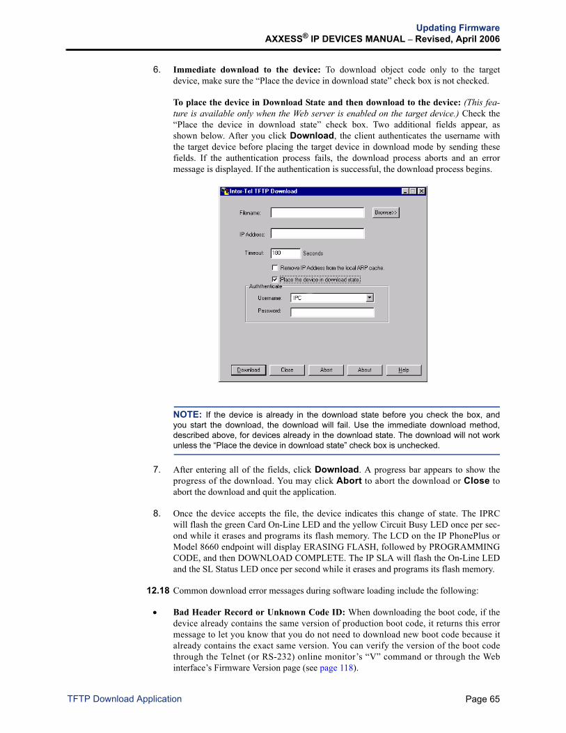
Updating FirmwareAXXESS® IP DEVICES MANUAL – Revised, April 2006
6. Immediate download to the device: To download object code only to the targetdevice, make sure the “Place the device in download state” check box is not checked.
To place the device in Download State and then download to the device: (This fea-ture is available only when the Web server is enabled on the target device.) Check the“Place the device in download state” check box. Two additional fields appear, asshown below. After you click Download, the client authenticates the username withthe target device before placing the target device in download mode by sending thesefields. If the authentication process fails, the download process aborts and an errormessage is displayed. If the authentication is successful, the download process begins.
NOTE: If the device is already in the download state before you check the box, andyou start the download, the download will fail. Use the immediate download method,described above, for devices already in the download state. The download will not workunless the “Place the device in download state” check box is unchecked.
7. After entering all of the fields, click Download. A progress bar appears to show theprogress of the download. You may click Abort to abort the download or Close toabort the download and quit the application.
8. Once the device accepts the file, the device indicates this change of state. The IPRCwill flash the green Card On-Line LED and the yellow Circuit Busy LED once per sec-ond while it erases and programs its flash memory. The LCD on the IP PhonePlus orModel 8660 endpoint will display ERASING FLASH, followed by PROGRAMMINGCODE, and then DOWNLOAD COMPLETE. The IP SLA will flash the On-Line LEDand the SL Status LED once per second while it erases and programs its flash memory.
12.18 Common download error messages during software loading include the following:
• Bad Header Record or Unknown Code ID: When downloading the boot code, if thedevice already contains the same version of production boot code, it returns this errormessage to let you know that you do not need to download new boot code because italready contains the exact same version. You can verify the version of the boot codethrough the Telnet (or RS-232) online monitor’s “V” command or through the Webinterface’s Firmware Version page (see page 118).
Page 65TFTP Download Application

Updating FirmwareAXXESS® IP DEVICES MANUAL – Revised, April 2006
C. TFTP SERVER
12.19 Unlike previous IP endpoints, the Model 8600 series endpoints (does not include theModel 8660) can use a TFTP server to update their firmware. This allows the endpoints to pullfirmware updates from a TFTP server automatically, rather than push firmware updates to indi-vidual endpoints. Freeware TFTP servers are widely available. The following descriptionfocuses on the Jounin TFTPD32 TFTP server (http://tftpd32.jounin.net).
Configuration Files
12.20 When the endpoints are connected to a PC that has the firmware update, the endpointsstart downloading two configuration files through the TFTP server in the order listed below:
• Global configuration file (globalcfg.cfg): Contains the default configuration ofall configuration parameters. This file is used to update firmware onto multiple end-points simultaneously. Use the global configuration file to set system-wide settings suchas the DHCP enable option, the TFTP server address, the SIP or ITP mode option, andif the endpoints connect to the same server, the IPRC or SIP Server port and address.
• Device-specific configuration file (xxxxxxxxxxxxcfg.cfg - where the x indi-cates the endpoint Ethernet address): Contains a subset of the configuration parametersspecific to the device. This file is used to update firmware onto an endpoint individu-ally. Use this file for device-specific settings such as static IP settings, the ITP logonpassword, the SIP extension and authentication information, or anything else that isspecific to this particular endpoint.
NOTE: The device-specific configuration file overwrites any configuration informationthat is in the global configuration file.
12.21 The endpoints then download the configuration files from the server periodically(defaults to one hour).
12.22 When the configuration file detects that the endpoint does not have the latest firmware,the endpoint also downloads the firmware update file (e.g., 8600_1_001.bin) from aTFTP server. This file contains the updated firmware information.
NOTE: You do not have to use the same TFTP server to download the firmware update andthe configuration files. In other words, you can download the files from anywhere.
12.23 To update firmware onto Models 8600, 8620/8622, 8662, and 8690, see page 68.
12.24 If the endpoint is unable to contact the TFTP server, it continues to use the last configu-ration stored in its flash or the configuration that the endpoint receives from the Axxess systemwhen in ITP mode.
NOTICEIt is strongly recommended that you upgrade all multi-protocol IP endpoints to the latestfirmware release. This will minimize potential conflicts when installing new endpoints atan existing site. The multi-protocol IP endpoint firmware is available at Inter-Tel’s edGeWeb site (www.inter-tel.com/software). For instructions about how to upgrade the firm-ware, see page 58.
Page 66 TFTP Server
Updating FirmwareAXXESS® IP DEVICES MANUAL – Revised, April 2006
NOTE: For the Model 8600 that has no display, use a DHCP server to assign the network set-tings and the TFTP server IP address to the endpoints, To do so, you must program the 66 and67 option tags, described in the table below, in the DHCP server. Without programming theseoptions, the endpoint cannot use the TFTP IP address and path from DHCP. Note that theDHCP options can be used for all multi-protocol endpoints, not just the 8600.
Determine the IP address of a Model 8600
12.25 This section provides recommended methods to determine the IP address of an Model8600 that does not have a display.
NOTE: The following methods work for the other Model 8600 series endpoints as well, but theother endpoints have a display to show their IP address.
12.26 If there is no DHCP server on the LAN:
1. Hold and to power up the endpoint. Release the buttons when the lamps turn offand the tone sounds. The endpoint is in self-test mode and uses the Inter-Tel default IPaddress of 192.168.200.201.
2. Configure a PC on the same LAN with a similar IP address (for example,192.168.200.202), and web to the device to complete the configuration of the endpoint.
12.27 If there is a DHCP server on the LAN:
1. Hold and during power up to default its configuration. This step ensures that theendpoint will attempt to retrieve an IP address from a DHCP server.
2. Program the endpoint’s MAC address on an IPRC on the same LAN as the endpoint.When the endpoint connects to the IPRC from ITP mode, check the IPRC or AxxessDatabase Programming to determine the IP address of the endpoint.
DHCP OPTION TAG DESCRIPTIONS
66 Specifies the TFTP server IP address. The value of this option tag cannot contain the TFTP server domain name.
67 Specifies the TFTP server path where the configuration resides. If this tag is not provided, the endpoint assumes that the configuration files are located in the root of the TFTP server path.
#
7 8
Page 67Determine the IP address of a Model 8600

Updating FirmwareAXXESS® IP DEVICES MANUAL – Revised, April 2006
Update Firmware onto Models 8600 Series Endpoints
12.28 To update firmware onto Models 8600, 8620/8622, 8662, and 8690:
1. Run tftpd32.exe. The following screen appears.
2. The Current Directory field should be automatically populated. If not, enter (or browset o ) t h e d i r e c t o r y p a t h t h a t c o n t a i n s t h e f i r m w a r e u p d a t e ( e . g . ,192.168.200.201\sip_configs\8690_2_3_2\bin). The Server interfaces field is automati-cally populated and does not need to be changed.
NOTE: If you are entering a directory path manually, use backslash (\) for the 8690User Interface Image and Windows CE Image URLs, and use forward slash (/) for theModels 8600, 8620/8622, and 8662 Image URLs and the 8690 Call Control Image URL.For details about images, see the following page.
CAUTION
Device Inoperability. To successfully update the firmware on a Model 8690 endpoint, youmust use a TFTP server client that is capable of file transfers greater than 32 MB. (One ofthe three Model 8690 firmware update files is greater than 32 MB.) Currently, the onlyknown TFTP client with this capability is a freeware application called Jounin TFTPD32(http://tftpd32.jounin.net). If another TFTP client is used, and it cannot transfer files greaterthan 32 MB, the partially downloaded file will be corrupted and render the Model 8690inoperable. There is no restore procedure other than to return the endpoint to Inter-Tel forrepair or replacement.
Page 68 Update Firmware onto Models 8600 Series Endpoints

Updating FirmwareAXXESS® IP DEVICES MANUAL – Revised, April 2006
3. Click Settings and check Allow ‘\’ As virtual root and Translate UNIX Filena-mes from the Advanced TFTP Options. Then click OK.
Once a connection is established, the connection log appears in the display, as shownbelow.
4. When the endpoint pulls its configuration files from a TFTP server, update one of theconfiguration files as described below. Sample configuration files are shown on the fol-lowing pages. For complete information about configuration parameters, see page 158.
For Models 8600, 8620/8622, and 8662, update the following fields (under SoftwareImage) in the configuration files. • xxxx_image_ver: (where the xxxx indicates the model name, such as the 8622):
Change or add the new version number as follows:— With versions 1.0.x, change the file name to “xxxx_image_ver: v.v.v” where
the v.v.v indicates the version number, such as 1.0.33.
— With versions 1.1.x, change the file name to “xxxx_image_ver: HWID 1 v.v.v”where the v.v.v indicates the version number, such as 1.1.5.
NOTE: Updating to versions 1.1.x, if the “HWID 1” portion of the version stringis missing, the endpoint will flash the error message “ERROR WRONG VER-SION” when attempting to download the image (see page 201 for details).
• xxxx_image_url (where the xxxx indicates the model name, such as the 8662):Change or add the URL of your TFTP server; e.g., “8600_image_url: 10.0.0.11/8600_updates/8600_1_001.bin.” Be sure to include any paths from the TFTP rootto the software update.
Page 69Update Firmware onto Models 8600 Series Endpoints

Updating FirmwareAXXESS® IP DEVICES MANUAL – Revised, April 2006
Firmware Update Changes: When upgrading an 8620, 8622, or 8662 endpoint, usethe following version strings.
From 1.01S to 1.0.31
86xx_image_ver: 1.0.31 (where the 86xx indicates the model type, such as 8622)
86xx_image_url: 192.168.200.202/86xx/86xx_1_0_31.bin
From 1.01S or 1.0.31 to 1.0.33
86xx_image_ver: 1.0.33
86xx_image_url: 192.168.200.202/86xx/86xx_1_0_33.bin
From 1.0.33 and earlier to 1.1.5
86xx_image_ver: HWID 1 1.1.5
86xx_image_url: 192.168.200.202/86xx/86xx_1_1_5.bin
NOTE: If upgrading an 8622 from 1.01S to 1.1.5, use the following image versionstring: 8620_image_ver: 8620 HWID 1 1.1.5.
From 1.1.5 and earlier to 2.0.06
86xx_image_ver: HWID 2 2.0.06
86xx_image_url: 192.168.200.202/86xx/86xx_2_0_06.bin
For future releases (2.0 and later)
itphone_image_ver: v.v.vv (where the v.v.vv indicates the firmware version, such as2.0.06)
itphone_image_url: 192.168.200.202/itphone/itphone_v_v_vv.bin (where the v_v_vvindicates the firmware version, such as 2_0_06)
NOTE: After an endpoint is updated to the v2.0.06 or later firmware, the86xx_image_ver and _url strings are no longer necessary. There are only two lines inthe configuration f i les that need to be modif ied ( i tphone_image_ver anditphone_image_url), and there is only one image to be put on the TFTP server toupdate all of the multi-protocol endpoints (excluding the Model 8690).
For the Model 8690, update the following three software components (six fields total),as described above.
• Call Control Image (8690_dsp_image_ver and 8690_dsp_image_url): Indicatesthe version or URL of the call control. The dsp indicates digital signal processing.
• Windows CE Image (8690_os_image_ver and 8690_os_image_url): Indicates theversion or URL of the Windows CE .NET. The os indicates an operating system.
• User Interface Image (8690_gui_image_ver and 8690_gui_image_url): Indicatesthe version or URL of the user interface. The gui indicates a graphical user inter-face.
NOTE: If the gui or os image version string does not match the version of the file spec-ified by image url, then the endpoint will continually prompt you to upgrade.
You could also change the “xxxx_image_ver” and “xxxx_image_url” fields through theWeb interface on the endpoint. See page 145 for information about the IP Phone WebClient.
Page 70 Update Firmware onto Models 8600 Series Endpoints

Updating FirmwareAXXESS® IP DEVICES MANUAL – Revised, April 2006
NOTE: If the endpoint pulls configuration files from a TFTP server in addition to updat-ing the Web interface, then the configuration files on the TFTP server will overwrite anychange you make through the Web interface on the endpoint.
5. Wait for the endpoint to re-synchronize its configuration or force it to re-synchronizethrough the Web interface on the endpoint (see page 157).
Firmware Download Progress Displays
12.29 Several changes have been made to the firmware image update process.
NOTE: These changes only apply when the endpoint is running version 2.0.06 or later firm-ware (not when upgrading from 1.1.5 to 2.0.06, for example).
• Two copies of the firmware image are kept in case one gets corrupted during a faileddownload attempt (this does not apply to the Model 8600 endpoints). This may causethe firmware update process to take more time than before.
• Additional messages are displayed on the LCD during the firmware download processso the user knows the current firmware download state and does not accidentally inter-rupt the process (i.e., unplug the endpoint thinking that it has hung up). The table on thenext page lists the updated progress displays.
NOTE: If an error occurs during the firmware download process, the endpoint displaysan error message described on page 73.
Firmware Download Startup
12.30 An endpoint with v2.0.06 or later firmware is disconnected from Call Processing whiledownloading an image. This prevents any incoming or outgoing calls from taking place.
Table 6: Firmware Download Progress Displays
DISPLAY DESCRIPTIONDOWNLOAD IN PROGRESS
The endpoint is downloading the image from the TFTP server.
ERASING PRIMARY FLASH
(New) The endpoint is erasing primary flash. The endpoint is preparing to program the primary flash with the new software image. This message is usually only shown briefly.
WRITING IMAGE TO PRIMARY FLASH
(New) The endpoint is programming the image to the primary flash.
ERASING BACKUP FLASH
(New) The endpoint is erasing backup flash. The endpoint uses the backup flash as a place holder when downloading the image or as a backup storage to restore the image in case the primary flash is corrupted. This message is usually shown briefly.
WRITING IMAGE TO BACKUP FLASH
(New) The endpoint is programming the image to the backup flash.
FIRMWARE DOWN-LOAD SUCCESS
The endpoint has successfully updated the firmware. The end-point will reset.
Page 71Firmware Download Progress Displays

Updating FirmwareAXXESS® IP DEVICES MANUAL – Revised, April 2006
D. AUTOMATED BOOT CODE UPDATE
12.31 The Models 8620, 8622, and 8662 endpoints with v2.0.06 or later firmware can nowuse a TFTP server to update their boot code. This works very similar to the firmware updates.The endpoint checks configuration from the TFTP server and reads new parameters either onstartup, by user request, or from periodic timeout. If the boot version in the configuration file isdifferent from the version currently on the endpoint, then the endpoint initiates the boot updateprocedure and downloads the new boot code. Note that the endpoint will delay this action ifthere is an audio stream, such as when on a call or music on hold is enabled.12.32 The following parameters must be set in the global configuration file.Boot Image Updates
itphone_boot_ver: v.v.vv (where the v.v.vv indicates the version number, such as 2.0.06)
itphone_boot_url: 192.168.200.202/itphone/itphone_v_v_vv_boot.bin (where the v_v_vv indi-cates the version number, such as 2_0_06)
Boot Code Download Progress Displays
12.33 The following table lists the progress displays that appear on the endpoint during theboot update procedure.
NOTE: If an error occurs during the boot code download process, the endpoint displays anerror message described on page 73.
Boot Image Changes
12.34 The boot image requires that the boot image version, including the hardware ID andplatform type be stored in the last x bytes of the boot image. For example:
…<NULL>ITPHONE:2:2.0.06<NULL>9219b198ce21bd806796fddf98f74f2e<EOF>
12.35 The checksum is a 32-character (128 bit or 16 byte) MD5 checksum. The checksumevaluates the image and image version, but not the last NULL and the checksum itself.
Table 7: Boot Code Download Progress Displays
DISPLAY DESCRIPTIONBOOT DOWNLOAD IN PROGRESS
(New) The endpoint is downloading the specified boot image from the TFTP server.
FORMATTING BOOT IMAGE
(New) The endpoint formats the boot image area.
WRITING BOOT TO FLASH
(New) If the image passes all tests, then the endpoint writes the image to flash.
VERIFYING WRITE (New) This message is displayed when the endpoint reads and per-forms a checksum check of the boot image on flash. If the check fails, then the endpoint returns to the Writing the boot to flash state.
BOOT DOWNLOAD SUCCESS
(New) If the boot is successfully written, then the endpoint will reset.
CAUTION
Unlike firmware updates, if the boot code download procedure is interrupted by a poweroutage or human intervention (for example, unplugging the endpoint power cord), the end-point will become inoperable and cannot be recovered. If this occurs, you must return theendpoint for repair.
Page 72 Automated Boot Code Update

Updating FirmwareAXXESS® IP DEVICES MANUAL – Revised, April 2006
E. DOWNLOAD ERROR MESSAGE DISPLAYS12.36 The endpoint now displays error information concerning the status of the last TFTPapplication image update (firmware or boot code) not only on the LCD but also on the Webinterface. The error message is displayed under Status - Image Upgrade - Last Download Error(see page 157). The following table lists the possible error messages.
Table 8: Image Download Error Message Displays
DISPLAY DESCRIPTIONERROR TFTP FAIL The image download process failed because of one of the following
problems:
• The endpoint cannot contact the TFTP server.
• The TFTP server does not have the software image file.
• The TFTP image URL contains the wrong path.
• The TFTP server does not have the permission to read the soft-ware image file.
ERROR TFTP FAIL START
The endpoint failed to start TFTP client. This problem could be due to an insufficient file descriptor for TFTP, etc.
ERROR BAD FLASH The image download process failed because of a faulty flash memory device or the flash file system is corrupted. If the user encounters this error, replace the device.
ERROR TFTP TIME-OUT
The endpoint failed to communicate with the TFTP server. This error could be due to bad network connectivity.
ERROR WRONG VERSION
The image contains an unexpected software version.
ERROR WRONG PLATFORM
The image contains an unexpected platform identifier.
ERROR MISC ERROR
Miscellaneous errors include a corrupted file system, unrecognized error by the TFTP library, etc.
ERROR NOT GZIP The image is not in GZIP format.
ERROR INVALID FILE ID
The image does not contain the appropriate file identifier.
ERROR INCOMPATI-BLE HW (previously called ERROR WRONG HWID)
The image contains the wrong hardware ID.
ERROR FILE TOO BIG
(New) The file that the endpoint downloaded for upgrade is too large.
ERROR BOOT IMAGE CORRUPT
(New) The boot image downloaded is corrupt.
ERROR ALLOCATE FAILURE
(New) The endpoint was unable to allocate enough memory to down-load the image.
ERROR FAILED VERIFY
(New) The image written to flash does not match the file downloaded (i.e. there was a write error).
Page 73Download Error Message Displays

Updating FirmwareAXXESS® IP DEVICES MANUAL – Revised, April 2006
FIGURE 6. Sample Global Configuration File
Continued on the next page...
Page 74 Image Download Error Message Displays

Updating FirmwareAXXESS® IP DEVICES MANUAL – Revised, April 2006
FIGURE 6. Sample Global Configuration File (Continued)
Update Required
Continued on the next page...
Page 75Image Download Error Message Displays

Updating FirmwareAXXESS® IP DEVICES MANUAL – Revised, April 2006
FIGURE 6. Sample Global Configuration File (Continued)
Page 76 Image Download Error Message Displays

Updating FirmwareAXXESS® IP DEVICES MANUAL – Revised, April 2006
FIGURE 7. Sample Device-Specific Configuration File
Continued on the next page...
Page 77Image Download Error Message Displays

Updating FirmwareAXXESS® IP DEVICES MANUAL – Revised, April 2006
FIGURE 7. Sample Device-Specific Configuration File (Continued)
Update Required
(Only if not configured in the global config file)
Continued on the next page...
Page 78 Image Download Error Message Displays

Updating FirmwareAXXESS® IP DEVICES MANUAL – Revised, April 2006
FIGURE 7. Sample Device-Specific Configuration File (Continued)
Page 79Image Download Error Message Displays

Programming the IP Devices on a v1.5.x Firmware IPRCAXXESS® IP DEVICES MANUAL – Revised, April 2006
13. PROGRAMMING THE IP DEVICES ON A V1.5.X FIRMWARE IPRC
NOTE: This section describes IP devices programming on a v1.5.x firmware IPRC. For infor-mation about IP devices programing on a v8.2.x firmware IPRC, see page 141.
13.1 The v1.5.x firmware IPRC and IP devices can be programmed using the followingmethods:
• Learn Mode (see below)
• Self-Programming Mode (see page 82)
• HTTP/Web Interface (see page 84)
• RS-232 Serial Connection — IPRC Only (see page 130)
• Telnet Session (see page 131)
NOTE: Do not change the IP card’s database while a call is active; it may drop all calls inprogress.
13.2 To upgrade a v1.5.x or earlier firmware to a v1.5.x firmware:
1. Make sure the software license supports the number of multi-protocol endpoints thatwill terminate on the IPRC.
2. Make sure it does not reside behind a firewall or NAT (see page 13 for details).
3. From the IPRC Administrative Session Web page, save the existing database in theevent it needs to be restored.
4. Remove the card from the cabinet and remove the PAL (located in slot U22).
5. If necessary, install the daughter card.
6. Place the card in the correct slot in the cabinet.
7. Run the Upload Utility and upload the 8.x firmware to the IPRC and the IP devices thatterminate at the card. For details about updating firmware, see page 58.
8. Under System\Cabinets, change the card type to Internet Protocol Resource Card(32-Device).
NOTE: If you have a v8.2 or later Axxess system, refer to the Addendum to the Axxessv8.0 Installation and Maintenance Manual or the latest version of the Inter-Tel AxxessInstallation and Maintenance Manual for details.
9. Under System\Cabinets\<IPRC>, program the card settings using the IPRC Web pageas a guide.
10. Under System\Cabinets\<IPRC>\Devices, program the IP devices, using the IPRC Webpage as a guide.
13.3 You can now program the IP devices to terminate at the card in Database Programming.
Page 80 Programming the IP Devices on a v1.5.x Firmware IPRC

Programming the IP Devices on a v1.5.x Firmware IPRCAXXESS® IP DEVICES MANUAL – Revised, April 2006
A. LEARN MODE
13.4 The IP devices have a mode that allows the IP card to “learn” the Ethernet address of anIP device. When power is applied to an IP device, the device first attempts to connect locallyusing broadcast messages on the LAN. If a local IP card does not respond, the IP deviceattempts to connect to its default IP card address. If the default IP card does not respond, the IPdevice broadcasts a Learn Mode message and then begins the cycle over.
13.5 Setting the Ethernet Address field of a circuit to 000000000000 puts the circuit intoLearn Mode. The circuit’s device type in the Device Flags field must also be set to the correcttype or Any Device in the RS-232/Telnet Device Programming. If an IP card receives a LearnMode message from an IP device, the IP card programs the IP device’s Ethernet address intothe first circuit on the IP card that is in Learn Mode. The IP card also updates the circuit’sdevice type to match the new device.
NOTE: A single IP card may have multiple circuits in Learn Mode, but multiple IP cards mustnot have circuits in Learn Mode at the same time.
Page 81Programming the IP Devices on a v1.5.x Firmware IPRC

Programming the IP Devices on a v1.5.x Firmware IPRCAXXESS® IP DEVICES MANUAL – Revised, April 2006
B. SELF-PROGRAMMING MODE
13.6 The self-programming mode allows you to program the IP endpoints, such as the IPPhonePlus and Model 8660, through the dialpad.
13.7 To use the self-programming mode:
1. While pressing and together on your endpoint, unplug and replace the endpointpower cord. The endpoint enters the self-programming mode and the following screenappears on the endpoint display.
2. Select one of three options: Program Database, Default Database, or Exit using themenu selection button next to the LCD.
The PROGRAM DATABASE option allows you to program the database through aseries of screens that follow. The DEFAULT DATABASE option allows you to usepredefined defaults for the database. The EXIT option allows you to exit the self-pro-gramming mode without making any changes.
Program Database
13.8 Follow the displays below and complete the programming. For details about REVERT,EXIT, <<, and >>, see paragraph 13.9 on the next page.
DISPLAY STATUS
STATIC IPxxx.xxx.xxx.xxx
Static IP: Enter the static IP address (defaults to 192.168.200.201).
STATIC SUBNETxxx.xxx.xxx.x
Default Static Subnet Mask: Enter the default static subnet mask (defaults to 255.255.255.0).
DEFAULT GATEWAYxxx.xxx.xxx.xxx
Default Static Gateway: Enter the default static gateway address (defaults to 192.168.200.201).
REMOTE IPC IPxxx.xx.xx.xxx
Remote IPC IP Address: Enter the remote IPRC IP address (defaults to 172.16.15.152).
HOSTNAME Hostname: This option allows you to program a hostname (up to 15 characters). To program the hostname, follow the instructions above.
BOOTP?xxxxxxxx
BOOTP: This option allows you to program the option to use BOOTP. The second line from the top indicates the current status (either ENABLED or DISABLED).
To program this option: Select either ENABLED or DISABLED. The endpoint updates the display to reflect the new change.
DHCP?xxxxxxxx
DHCP: This option allows you to program the option to use DHCP. The second line from the top indicates the current status (either ENABLED or DISABLED).
To program this option: Select either ENABLED or DISABLED. The endpoint updates the display to reflect the new change.
7 8
MENUSELECTIONBUTTONS
MENUSELECTIONBUTTONS
P R O G R A M M I N G M O D E
P R O G R A M D A T A B A S ED E F A U L T D A T A B A S EE X I T
Page 82 Self-Programming Mode

Programming the IP Devices on a v1.5.x Firmware IPRCAXXESS® IP DEVICES MANUAL – Revised, April 2006
13.9 To program the IP address:
1. Press a dialpad button to enter the IP address. The entire second line, except the dots,disappears, and the number you entered appears in the first space. serves as abackspace button, and , , or moves the cursor to the next space after thedot.
NOTE: Pressing deletes the numbers without deleting the dots.
You have the following options:
• Revert: Reverts to the old value found in the current database, and the endpointupdates the display accordingly.
• Exit: Exits to the confirmation screen (last screen) without scrolling through all theother options. Refer to page 83 for more details on the confirmation screen.
• >>: Continues to the next screen in the series.
• <<: Returns to the previous screen in the series. Note that this option does notappear on the Static IP Programming screen.
2. Once you have finished programming, select either EXIT, >>, or <<. The endpoint willcheck the field for errors.
• If there are no errors, the endpoint displays the next programming screen.
• If there are errors, the endpoint displays INVALID ENTRY. Correct the error byeither selecting REVERT or modifying the incorrect entry.
Default Database and Exit
13.10 When you have scrolled through all the options, selected EXIT from any of the screens,or selected DEFAULT DATABASE from the initial screen, the following screen appears toconfirm the changes.
13.11 You have the following options:
• Yes: Overwrites the database. If you select this option, the CHANGES SAVED screenwill appear to notify you that the changes have been saved. To continue initializing theendpoint, press any button.
• No: Leaves the database as it was. If you select this option, the NO CHANGESSAVED screen appears to notify you that the changes have been discarded. To continueinitializing the endpoint, press any button.
• <<: Returns to the previous screen in the series.
S A V E C H A N G E S ?
Y E SN O< <
MUTE
FWD #
MUTE
Page 83Default Database and Exit

Programming the IP Devices on a v1.5.x Firmware IPRCAXXESS® IP DEVICES MANUAL – Revised, April 2006
C. HTTP/WEB INTERFACE METHOD
NOTE: Unlike prior versions of IPRC firmware, the v8.1 IPRCs cannot be programmed throughthe IPRC Administrative Session Web page. The HTTP/Web Interface for the IPRC v8.2.x firm-ware is only used for diagnostics and troubleshooting purpose (see page 205). You must pro-gram the v8.1 IPRCs and IP devices through Axxess system Database Programming. Fordetails about programming a v8.1 IPRC and IP devices, refer to the Addendum to the Axxessv8.0 Installation and Maintenance Manual.
13.12 The HTTP/Web interface called the IPRC Administration Session allows you to use aWeb browser to connect to the IPRC v1.5.x firmware or any of the IP devices for DatabaseProgramming. Each IP card and IP device contains an embedded Web server. For informationabout the Networking IPRC Administrative Session, refer to the v8.0 or later Axxess Installa-tion and Maintenance Manual.
NOTE: Your Web browser must be Internet Explorer v4.0 or later or Netscape v4.0 or later.
13.13 To use the IPRC Administration Session:
1. Make sure the IP device is powered up, connected, and online. Then point a Webbrowser to the IP address of the device. The default IP address for the IPRC and IPdevices is 192.168.200.201. The screen shown below appears.
2. Log in with your username and password. The default usernames and passwords areshown below. To prevent unauthorized access, you should change the password ofthe IP card and its devices as soon as possible. To change the login passwords, seepage 97 for the IP card and page 106 for IP devices.
NOTE: The usernames and passwords are case-sensitive. Also, if you have troubleconnecting to the IP card using your usual Database Programming password whileusing Microsoft Internet Explorer 4.0 or later, disable the “connect with proxy server”option.
DEVICE USERNAME PASSWORD
IPRC IPRC itpassw
IP Devices IPT iptpassw
Page 84 HTTP/Web Interface Method

Programming the IP Devices on a v1.5.x Firmware IPRCAXXESS® IP DEVICES MANUAL – Revised, April 2006
3. The programming options, shown in the table below, are displayed along the left edgeof the screen. Select the desired programming option and follow the instructions givenin the following pages.
NOTE: For details about SIP-specific configuration, refer to the latest version of the SIP ServerInstallation and Configuration Manual.
CARD CONFIGURATION(IP Card Programming)
REF. PAGE
DEVICE CONFIGURATION(IP Devices Programming)
Quick Setup Not Available• Card 86• Device 88
Card Configuration Device Configuration• Network 93 • Network
• Audio and Call Control 95 • Audio and Call Control
• Change Login Password 97 • Change Login Password
Circuit Configuration Not Available• Device Type 98• Device Information 99• Network 100• Advanced Network 101• Call Control 103• Audio Settings 104• Advanced Audio Settings 106• Device Login Password 110• Device Specific 111
Status Status• Firmware Version 118 • Firmware Version
• Network 118 • Network
• Receive Audio 119 • Receive Audio
• Circuits 121Command Command
• Reset 122 • Reset
• Reset Circuits 123• Download 125 • Download
Database Not Available• Save 125• Restore 126• Default 126
Not Available 10/100 Switch (for Model 8660 only)
127 • Program Switch
128 • Default Switch
Miscellaneous Miscellaneous• Date & Time 129 • Date & Time
Page 85HTTP/Web Interface Method

Programming the IP Devices on a v1.5.x Firmware IPRCAXXESS® IP DEVICES MANUAL – Revised, April 2006
Quick Setup — Card
13.14 When you select Card, the following page appears.
13.15 Program the fields as described below. When finished, click OK to save your changesor Cancel to exit without changing the settings.
• Obtain IP Address automatically (DHCP): Select this option to set the IP addressautomatically.
NOTE: It is recommended that you do not obtain an IP address for the IP card auto-matically. If the address changes, the IP endpoint will no longer know what address touse.
• Using the following IP address: Enter the IP address, subnet mask, and default gate-way in the text boxes. The following table describes the information required for eachfield.
• The IP Card is behind the firewall, NAT or proxy server: If the IP card is behind thefirewall, NAT, or proxy server, check this option and enter the IPRC public address thatis located outside the firewall or proxy server. For more information, see “OperationBehind Firewalls or Proxies” on page 13.
FIELD (AND DEFAULT VALUE) FIELD DESCRIPTION
IP Address (192.168.200.201)
Defines the default IP address for the IPRC. If the card does not receive a BOOTP or DHCP response, it uses this IP address. If 0.0.0.0 is entered, the server reports an error. IP address 0.0.0.0 and 255.255.255.255 are invalid IP addresses.
Subnet Mask (0.0.0.0) Defines the default network subnet mask for the IP device. If the card does not receive a BOOTP or DHCP response, it uses this subnet mask.
Default IP Gateway (0.0.0.0)
Defines the default IP gateway or router address for the IPRC. If the card does not receive a BOOTP or DHCP response, it uses this IP gateway address.
Page 86 Quick Setup — Card

Programming the IP Devices on a v1.5.x Firmware IPRCAXXESS® IP DEVICES MANUAL – Revised, April 2006
13.16 When you click OK, the following page appears. Click Circuit Installation to con-tinue installing the circuits, or click <Back to go back and change the Internet protocol set-tings of the card.
Page 87Quick Setup — Card

Programming the IP Devices on a v1.5.x Firmware IPRCAXXESS® IP DEVICES MANUAL – Revised, April 2006
Quick Setup — Device
NOTE: Before using the Device Quick Setup page, ensure that the browser has cookiesenabled. To enable the cookies:
— For Internet Explorer v4.x: Select View - Internet Options - Advanced. Scroll down toCookies in the Security section. Enable Always accept cookies. Then, click OK.
— For Internet Explorer v5.x and later: Select Tools - Internet Options - Security. Click Cus-tom Level. Then, scroll down to Cookies and enable both Allow cookies that are stored onyour computer and Allow per-session cookies (not stored). Then, click OK.
— For Netscape Navigator v4.x and later: Select Preferences from the Edit menu. SelectAdvanced (or Privacy and Security) from the tree selection on left of the screen. Then, underthe Cookies section, check Accept All cookies (or Enable all cookies). Then, click OK.
13.17 To configure a device:
1. Device Type: When you select Device, the following page appears. Select the circuitnumber you would like to configure, and select the device type you are using.
If you are configuring an IP PhonePlus (or Model 8660 endpoint), IP Single-LineAdapter, IP softphone, or IPP+/IPSLA/IPSOFT, skip to step 3 If you are configuring an MGCP Gateway Device with Endpoint, skip to step 4 If you are configuring an MGCP Gateway Additional Endpoint, skip to step 5
2. Click Next> to continue configuring the device or Cancel to exit without changing thesettings.
Page 88 Quick Setup — Device

Programming the IP Devices on a v1.5.x Firmware IPRCAXXESS® IP DEVICES MANUAL – Revised, April 2006
3. For an IP PhonePlus (or Model 8660 endpoint), IP Single-Line Adapter, IP soft-phone, or IPP+/IPSLA/IPSOFT:
e. IP Device Internet Protocol Settings: Program the network settings for thedevice. Check Obtain IP Address automatically (DHCP) to obtain an IPaddress automatically. Otherwise, enter the IP address, subnet mask, and defaultgateway address to be used as static network settings on the device. When finished,click Next>.
The following table describes the information required for each field.
f. IP Device Configuration: Program the device mode, device ID, and the remote IPcard IP address. By default, the remote IP card IP address is the current IP addressof the IP card. When finished, click Next>.
NOTE: If the IP card has a public IP address, you can select either the current IPaddress or the public IP address.
FIELD (DEFAULT VALUE) FIELD DESCRIPTION
IP Address (192.168.200.201)
Defines the default IP address for the IPRC. If the card does not receive a BOOTP or DHCP response, it uses this IP address. If 0.0.0.0 is entered, the server reports an error. IP address 0.0.0.0 and 255.255.255.255 are invalid IP addresses.
Subnet Mask (0.0.0.0) Defines the default network subnet mask for the IP device. If the card does not receive a BOOTP or DHCP response, it uses this subnet mask.
Default IP Gateway (0.0.0.0)
Defines the default IP gateway or router address for the IPRC. If the card does not receive a BOOTP or DHCP response, it uses this IP gateway address.
Page 89Quick Setup — Device

Programming the IP Devices on a v1.5.x Firmware IPRCAXXESS® IP DEVICES MANUAL – Revised, April 2006
The device mode contains the following options:
• Unused: If the current circuit is unused, the device ID address field is set toFF:FF:FF:FF:FF:FF. If the resulting configuration is updated, the effect willbe to disable the circuit.
• Learn Mode: Sets the device ID address to 00:00:00:00:00:00 and puts thecircuit into Learn Mode.
• Normal: If the current circuit is set to normal, the device ID reflects thedevice ID in the system database.
g. IP Device Configuration Continued: If you click Learn Mode or if you selectthe IP card public IP address as the remote IPRC IP address, the following pageappears. This page creates a temporary IP address. This way, the IP device can con-nect to the IP card during the installation before being deployed at a different net-work segment, WAN, or somewhere in the Internet. Click Yes or No to determineif the network segment that contains the IPRC has a DHCP server. When finished,click Next>.
h. Skip to step 64. For an MGCP Gateway Device + Endpoint:
a. MGCP Gateway Configuration: Select AudioCodes MP100. The MGCP man-ufacturer type is used to assign a default endpoint name to the first MGCP gatewayendpoint name. If the MGCP gateway device is not AudioCode, select Other.Then, enter the IP address of the MGCP gateway device. When finished, clickNext>.
Page 90 Quick Setup — Device

Programming the IP Devices on a v1.5.x Firmware IPRCAXXESS® IP DEVICES MANUAL – Revised, April 2006
b. MGCP Endpoint Name Setting: By default, each gateway device must have anendpoint. The default endpoint name is shown based on the gateway manufacturetype. For instance, the default endpoint name for the AudioCode first endpoint isACgw0. This field cannot be blank. When finished, click Next>.
c. Skip to step 6
5. For an MGCP Gateway Additional Endpoint:
a. MGCP Endpoint Setting: Select the MGCP gateway device number to which theendpoint belongs. When finished, click Next>.
b. MGCP Endpoint Name Setting: By default, each gateway device must have anendpoint. The default endpoint name is based on the gateway manufacture type.For instance, the default endpoint name for the AudioCodes first endpoint isACgw1. This field cannot be blank. When finished, click Next>.
c. Proceed to the next step.
6. Preparing to Connect: Plug in the IP device to the network before the final stage ofthe installation. When finished, click Next>.
ACgw0
Page 91Quick Setup — Device

Programming the IP Devices on a v1.5.x Firmware IPRCAXXESS® IP DEVICES MANUAL – Revised, April 2006
7. Connecting Device: Wait for two minutes for the IP device to connect to the IP card.At this point, all the database changes made from the previous pages are committed tothe database.
Page 92 Quick Setup — Device

Programming the IP Devices on a v1.5.x Firmware IPRCAXXESS® IP DEVICES MANUAL – Revised, April 2006
Card or Device Configuration — Network
NOTE: This page contains the same fields for both card and device programming.
13.18 When you select Network, the following page (or one similar to this) appears.
13.19 Program the fields as described below. When finished, click one of the following but-tons:
• Update: Saves your changes.• Refresh: Restores all fields to the current values stored in the database. • Reset Fields: Restores the fields to the values that were displayed when you opened the
page.13.20 The following table describes the information required for each field.
FIELD (AND DEFAULT VALUE) FIELD DESCRIPTION
Static (Default) IP Address (192.168.200.201)
Defines the default IP address for the IP device. If the card does not receive a BOOTP or DHCP response, it uses this IP address. If you enter 0.0.0.0, the server defaults to 192.168.200.201.
Default Network Subnet Mask (0.0.0.0)
Defines the default network subnet mask for the IP device. If the card does not receive a BOOTP or DHCP response, it uses this subnet mask.
Default IP Gateway Address (0.0.0.0)
Defines the default IP gateway or router address for the IP device. If the card does not receive a BOOTP or DHCP response, it uses this IP gateway address.
WINS Server (0.0.0.0) Indicates the IP address that the device should use to find the Windows Internet Name Service (WINS) server to register its hostname. The default is 0.0.0.0, which indicates no WINS server.
Hostname Identifies the device on the network. This string can be up to 15 characters.
IP Address Assignment (DHCP) Place checks in the appropriate box(es) to determine the method(s) in which the IP device obtains its IP Address.
NOTE: If both check boxes are selected during initialization, the IP device performs a BOOTP request first. If it fails to get an IP address by BOOTP, it sends the DHCP request. If DHCP fails, the IP device uses the IP address in the Default IP Address field. If none of the check boxes are selected, the IP device uses the address in the Default IP Address field after boot up. Changes will take effect after the device resets.
Page 93Card or Device Configuration — Network

Programming the IP Devices on a v1.5.x Firmware IPRCAXXESS® IP DEVICES MANUAL – Revised, April 2006
Web Server (Enabled)Telnet Server (Enabled)
Defines whether the Web server and/or Telnet server is enabled. Changing these fields will take effect immediately; you do not have to reset the IP device.
NOTE: Do not disable both the Web server and the Telnet server, unless you only want to allow access to configuration settings by using one of the IPRC’s serial ports. Unlike an IPRC, the IP devices (IP PhonePlus, IP SLA, and Model 8660 endpoint) do not have serial ports. However, you can still access to configuration settings using the self-programming mode.
FIELD (AND DEFAULT VALUE) FIELD DESCRIPTION (Continued)
Page 94 Card or Device Configuration — Network

Programming the IP Devices on a v1.5.x Firmware IPRCAXXESS® IP DEVICES MANUAL – Revised, April 2006
Card or Device Configuration — Audio & Call Control
NOTE: This page contains the same (or similar) fields for both card and device programming.
13.21 When you select Audio & Call Control, the following page (or one similar to this)appears.
NOTE: For Device Configuration, be sure to change these values on the IP card before chang-ing them on the IP device. Otherwise, when the device connects to the IP card, it will receivethe old database values from the IP card.
13.22 Program the fields as described below. When finished, click one of the following but-tons:
• Update: Saves your changes.
• Refresh: Restores all fields to the current values stored in the database.
NOTE: If there is a call in progress, ensure to reflesh this page to get the latest infor-mation.
• Reset Fields: Restores the fields to the values that were displayed when you opened thepage
13.23 The following table describes the information required for each field.
FIELD (AND DEFAULT VALUE) FIELD DESCRIPTION
TCP Call Control Port (5566) Receives call control messages from IP devices. The port number should only be changed for extremely rare circumstances.
UDP General Purpose Port (5567)
Sends and receives connection messages to and from IP devices. The port number should only be changed for extremely rare circumstances. The IP devices use this port number to find and connect to the IP card.
Audio Stream Receive Port (5004)
Receives RTP audio data from all IP devices. The port number should only be changed for extremely rare circumstances.
NOTE: With IPRC v1.5 firmware, you must change this setting to 2427 to connect to the MGCP.
The following fields are available in card configuration only.
Backplane Transmit Signal Gain (0dB)
Decreases the IP card transmit signal to the backplane. This could be use-ful in some cases to reduce echo. However, excessive negative values (attenuation) could result in a decreased audio volume. The range for this value is 0dB to -15dB.
Page 95Card or Device Configuration — Audio & Call Control

Programming the IP Devices on a v1.5.x Firmware IPRCAXXESS® IP DEVICES MANUAL – Revised, April 2006
Backplane Companding Type(Mu-Law)
Indicates the system backplane type (Mu-law or A-law).
RTP IP Precedence (Enabled) Defines whether the IP packet in the RTP stream uses the IP precedence feature. IP precedence allows some routers to apply priority queuing on the RTP packets.
Country (US) Can be set to US, UK, or Japan to control the single-line termination set-tings in the IP Single-Line Adapter and to control the DTMF levels on all devices. Changes will take effect after the device resets.
The following fields are available in device configuration only.
Remote IPRC IP Address (0.0.0.0)
The IP devices first attempt to connect to a local IP card by broadcasting messages on the LAN. If a local IP card does not respond to the IP device, the IP device attempts to connect to the default IP card address. This field must be programmed for the IP device to connect across a router. Changes to this field take effect after the device resets.
Audio Stream Send/Receive Port (5004)
Shows the port number to send/receive RTP audio data from all IP devices. that is programmed in the IPRC.
NOTE: With IPRC v1.5 firmware, you must change this setting to 2427 to connect to the MGCP.
Vocoder Type (Default) Shows the vocoder type that the IP device will attempt to use that is pro-grammed in the IPRC.
Audio Frames/IP Packet (Default) Shows the maximum number of RTP packets to stack in a single UDP packet that is programmed in the IPRC.
DTMF Encoding Setting (Default - 1-way):
Shows the encoding of DTMF tones that the IP device detects in the audio that it encode that is programming in the IPRC.
Voice Activity Detection (Dis-abled)
Shows the Voice Activity Detection setting that is programming in the IPRC. If this option is enabled, the system reduces bandwidth requirements by not sending voice packets when the user is not speaking. However, it is neces-sary for some calls, such as modem and fax calls, to turn off this detection.
FIELD (AND DEFAULT VALUE) FIELD DESCRIPTION (Continued)
Page 96 Card or Device Configuration — Audio & Call Control

Programming the IP Devices on a v1.5.x Firmware IPRCAXXESS® IP DEVICES MANUAL – Revised, April 2006
Card or Device Configuration — Change Login Password
NOTE: This page contains the same fields for both card and device programming.
13.24 When you select Change Login Password, the following page appears.
13.25 Enter the current password in the Current Password field, if there is one. Then enterthe new password once in the New Password field and again in the Confirm New Pass-word field.
NOTE: Passwords are case-sensitive. The New Password and Confirm New Password fieldsmust match exactly.
13.26 Program the fields as described below. When finished, click one of the following but-tons:
• Update: Saves your changes.
• Reset Fields: Restores the fields to the values that were displayed when you opened thepage.
NOTE: Changing the password is not a secure process. The new passwords submitted to theserver are not encrypted and, therefore, may be susceptible to password snooping. For IPRC passwords, you can use the RS-232 Card Programming for more security (seepage 133 for more details). For device passwords, because IPRCs overwrite the device's local password every time thedevice connects, it is recommended that you change the device password only in the IPRC Webpage.
Page 97Card or Device Configuration — Change Login Password

Programming the IP Devices on a v1.5.x Firmware IPRCAXXESS® IP DEVICES MANUAL – Revised, April 2006
Circuit Configuration — Device Type
13.27 When you select Device Type, the following page appears. Program the fields foreach circuit on the IP card or for the IP device as described below.
13.28 When finished, click one of the following buttons:
• Update: Saves your changes.• Refresh: Restores all fields to the current values stored in the database. • Reset Fields: Restores the fields to the values that were displayed when you opened the
page.13.29 The following table describes the information required for each field.
FIELD (AND DEFAULT VALUE) FIELD DESCRIPTION
Circuit Indicates which circuit on the IP card you are programming. It is also a hyper-link that will allow you to jump to the Device Specific page for that circuit (see page 111).
Device Description Is programmed in the Device Information (see page 99) or Device Specific (see page 111) page.
Device Type (IP PhonePlus) Identifies the type of IP device that can be connected to the circuit. The device types include the following:
• IP PhonePlus (or Model 8660)• IP Single-Line Adapter• IP SoftPhone• IPP+, IPSLA, IPSOFT• MGCP Gateway Device + Endpoint• MGCP Add’l Endpoint
MGCP Endpoint’s Gateway Device (0)
Indicates the gateway device number to which this gateway endpoint belongs.
NOTE: This field only appears if the device type is an MGCP Add’l Endpoint.
Page 98 Circuit Configuration — Device Type

Programming the IP Devices on a v1.5.x Firmware IPRCAXXESS® IP DEVICES MANUAL – Revised, April 2006
Circuit Configuration — Device Information
13.30 When you select Device Information, the following page appears. Program the fieldsfor each circuit on the IP card or for the IP device as described below.
13.31 When finished, click one of the following buttons:
• Update: Saves your changes.• Refresh: Restores all fields to the current values stored in the database. • Reset Fields: Restores the fields to the values that were displayed when you opened the
page.13.32 The following table describes the information required for each field.
FIELD (AND DEFAULT VALUE) FIELD DESCRIPTION
Circuit Indicates which circuit on the IP card you are programming. It is also a hyperlink that allows you to jump to the Device Specific page for that circuit (see page 111).
Device Description Enter a description of up to 16 characters to help you identify the device on this circuit. This description also appears in the other programming pages.
Device ID or Ethernet Address (FF:FF:FF:FF:FF:FF)
Contains the Ethernet address of the IP device that will connect to this circuit. The IP card uses the IP device’s Ethernet address as a unique identifier for the device. You can also use the following buttons:
• Learn Mode: Sets the Ethernet address to 00:00:00:00:00:00 and puts the circuit into Learn Mode (as described on page 81).
• Unused: If the current circuit is unused, the Ethernet address field is set to FF:FF:FF:FF:FF:FF. If the resulting configuration is updated, the effect will be to disable the circuit.
• Reset Field: Returns the field to its original value.
Host/Endpoint Name Identifies the device on the network. This string can be up to 15 characters. If the device is an MGCP gateway or endpoint, this string identifies the endpoint. Changing this field takes effect immediately; you do not have to reset the IP device.
Page 99Circuit Configuration — Device Information

Programming the IP Devices on a v1.5.x Firmware IPRCAXXESS® IP DEVICES MANUAL – Revised, April 2006
Circuit Configuration — Network
13.33 When you select Circuit Configuration — Network, the following page appears.
13.34 Program the fields as described below. When finished, click one of the following but-tons:
• Update: Saves your changes.
• Refresh: Restores all fields to the current values stored in the database.
• Reset Fields: Restores the fields to the values that were displayed when you opened thepage
13.35 The following table describes the information required for each field.
FIELD (AND DEFAULT VALUE) FIELD DESCRIPTION
Circuit Indicates which circuit on the IP card you are programming. It is also a hyper-link that allows you to jump to the Device Specific page for that circuit (see page 111).
Device Description Is programmed in the Device Information (see page 99) or Device Specific (see page 111) page.
Static (Default) IP Address (192.168.200.201)
Defines the static (default) IP address for the IP device on this circuit. If the device does not receive a BOOTP or DHCP response, it uses this address. Changes to this field take effect after the device is reset.
Default Network Subnet Mask (0.0.0.0)
Defines the default subnet mask for the IP device on this circuit. If the device does not receive a BOOTP or DHCP response, it uses this subnet mask. Changes to this field take effect after the IP device is reset.
Default IP Gateway Address (0.0.0.0)
Defines the default IP gateway or router address for the IP device on this cir-cuit. If the device does not receive a BOOTP or DHCP response, it uses this IP gateway address. Changes to this field take effect after the IP device is reset.
DHCP (Enabled)BOOTP (Enabled)
Defines the method(s) in which the IP device obtains its IP address. Changes will take effect after the device resets.
NOTE: If both the BOOTP and DHCP check boxes are selected, the IP device performs a BOOTP request first during bootstrap. If it fails to get an IP address by BOOTP, it sends the DHCP request. If DHCP fails, the IP device will use the IP address in the Default IP Address field. If none of check boxes are selected, the IP device uses the address in the Default IP Address field after boot up.
Page 100 Circuit Configuration — Network

Programming the IP Devices on a v1.5.x Firmware IPRCAXXESS® IP DEVICES MANUAL – Revised, April 2006
Circuit Configuration — Advanced Network
13.36 When you select Circuit Configuration — Advanced Network, the followingpage appears.
13.37 Program the fields as described below. When finished, click one of the following but-tons:
• Update: Saves your changes.• Refresh: Restores all fields to the current values stored in the database. • Reset Fields: Restores the fields to the values that were displayed when you opened the
page.13.38 The following table describes the information required for each field.
FIELD (AND DEFAULT VALUE) FIELD DESCRIPTION
Circuit Indicates which circuit on the IP card you are programming. It is also a hyper-link that allows you to jump to the Device Specific page for that circuit (see page 111).
Device Description Is programmed in the Device Information (see page 99) or Device Specific (see page 111) page.
WINS Server (0.0.0.0) Indicates the IP address that the device should use to find the WINS server to register its hostname. The default is 0.0.0.0, which indicates no WINS server.
BOOTP Client IP Address (0.0.0.0)
The IP card contains a BOOTP server. If the IP card receives a BOOTP request from the Ethernet address in the Ethernet Address field, the IP card sends the BOOTP IP address to the device. If this field is set to 0.0.0.0, the IP card will not send a BOOTP reply.
Enable Web Server (Enabled)Enable Telnet Server (Enabled)
Defines whether the Web server and/or Telnet server is enabled. Changing these fields will take effect immediately; you do not have to reset the IP device.
Page 101Circuit Configuration — Advanced Network

Programming the IP Devices on a v1.5.x Firmware IPRCAXXESS® IP DEVICES MANUAL – Revised, April 2006
Overwrite Device’s Local Set-tings (Enabled)
Determines whether the IP card will overwrite the network settings on the IP PhonePlus, Model 8660 endpoint, or IP SLA. If the check box is disabled, the IP card does not overwrite the device’s local network settings, and the user must program the device correctly through the IP PhonePlus or Model 8660 endpoint’s Self-Programming Mode or through the device’s Web or Telnet interfaces. The device never changes the IP card’s database. The network settings include only the following fields: Static (Default) IP Address, Default Network Subnet Mask, Default IP Gateway Address, Remote IPRC IP Address, UDP General Purpose Port, Hostname, BOOTP, and DHCP. Changes will take effect the next time the device attempts to connect to the IP card.
NOTE: Both endpoints, the IP card and the IP PhonePlus, Model 8660 end-point, or IP SLA, must be running version 1.2 or later for this feature to work.
FIELD (AND DEFAULT VALUE) FIELD DESCRIPTION (Continued)
Page 102 Circuit Configuration — Advanced Network

Programming the IP Devices on a v1.5.x Firmware IPRCAXXESS® IP DEVICES MANUAL – Revised, April 2006
Circuit Configuration — Call Control
13.39 When you select Circuit Configuration — Call Control while programming adevice, the following page appears.
13.40 Program the fields as described below. When finished, click one of the following but-tons:
• Update: Saves your changes.• Refresh: Restores all fields to the current values stored in the database. • Reset Fields: Restores the fields to the values that were displayed when you opened the
page.
NOTE: Be sure to change these values on the IP card before changing them on the IP device.Otherwise, when the device connects to the IP card, it will receive the old database values fromthe IP card.
13.41 The following table describes the information required for each field.
FIELD (AND DEFAULT VALUE) FIELD DESCRIPTION
Circuit Indicates which circuit on the IP card you are programming. It is also a hyperlink that allows you to jump to the Device Specific page for that circuit (see page 111).
Device Description Is programmed in the Device Information (see page 99) or Device Spe-cific (see page 111) page.
Remote IPRC IP Address (0.0.0.0) The IP devices first attempt to connect to a local IP card by broadcast-ing messages on the LAN. If a local IP card does not respond to the IP device, the IP device attempts to connect to the default IP card address. This field must be programmed for the IP device to connect across a router. Changes to this field take effect after the device resets.
MGCP Gateway Device IP Address (0.0.0.0)
Indicates the IP address of the gateway device, which the IP card uses to authenticate the MGCP gateway device.
Page 103Circuit Configuration — Call Control

Programming the IP Devices on a v1.5.x Firmware IPRCAXXESS® IP DEVICES MANUAL – Revised, April 2006
Circuit Configuration — Audio Settings
13.42 When you select Circuit Configuration — Audio Settings, the following pageappears.
13.43 Program the fields as described below. When finished, click one of the following but-tons:
• Update: Saves your changes.
• Refresh: Restores all fields to the current values stored in the database.
• Reset Fields: Restores the fields to the values that were displayed when you opened thepage.
13.44 The following table describes the information required for each field.
FIELD (AND DEFAULT VALUE) FIELD DESCRIPTION
Circuit Indicates which circuit on the IP card you are programming. It is also a hyperlink that allows you to jump to the Device Specific page for that circuit (see page 111).
Device Description Is programmed in the Device Information (see page 99) or Device Specific (see page 111) page.
Audio Stream Send Port (5004)
Contains the UDP port number that the IP card uses to send RTP packets to the IP device. Do not change this field while the IP device is connected to the IP card.
NOTE: With IPRC v1.5 firmware, you must change this setting to 2427 to connect to the MGCP.
Audio Frames/IP Packet (3)
Indicates the maximum number of RTP packets to stack in a single UDP packet. Increasing the number increases the audio delay but reduces the bandwidth and CPU load. This value should normally be 2 through 4. The default value allows the IP device to automatically choose a value. Changes to this field take effect when the IP device starts a new call. (This should be set to 1 for fax operation.)
Vocoder Type (Default) Defines the vocoder type that the IP device on this circuit will attempt to use. Possible values are: G.711 Mu-Law, G.711 A-Law, G.729, and Default. The Default option allows the IP device to automatically choose a value. Changes to this field take effect when the IP device starts a new call. (This should be set to G.711 for fax operation.)
Page 104 Circuit Configuration — Audio Settings

Programming the IP Devices on a v1.5.x Firmware IPRCAXXESS® IP DEVICES MANUAL – Revised, April 2006
Minimum Playback Buffer Time (ms) (80)
Indicates the amount of audio that the device buffers before playing. Available set-tings are 0, 20, 40, 60, 80, 100, 120, 140, 160, 180, or 200 ms. Increasing this field increases the amount of audio that the device buffers before playing. Doing this will increase the audio delay, but may improve the audio quality in some circumstances. If you enter a value that is too small for the IP device to use, the IP device will use the smallest value that it can. Optimum setting for the IP softphone is 200 ms and for fax operations the best setting is 160 ms.
FIELD (AND DEFAULT VALUE) FIELD DESCRIPTION (Continued)
Page 105Circuit Configuration — Audio Settings

Programming the IP Devices on a v1.5.x Firmware IPRCAXXESS® IP DEVICES MANUAL – Revised, April 2006
Circuit Configuration — Advanced Audio Settings
13.45 When you select Circuit Configuration — Advanced Audio Settings, the fol-lowing page appears.
13.46 Program the fields as described below. When finished, click one of the following but-tons:
• Update: Saves your changes.• Refresh: Restores all fields to the current values stored in the database. • Reset Fields: Restores the fields to the values that were displayed when you opened the
page.13.47 The following table describes the information required for each field.
FIELD (AND DEFAULT VALUE) FIELD DESCRIPTION
Circuit Indicates which circuit on the IP card you are programming. It is also a hyperlink that allows you to jump to the Device Specific page for that circuit (see page 111).
Device Description Is programmed in the Device Information (see page 99) or Device Specific (see page 111) page.
DTMF Encoding Setting (1-way)
Controls the encoding of DTMF tones that the IP card and IP SLA detect in the audio that they encode. (IP PhonePlus and Model 8660 endpoint always use an “Out-Of-Band” encoding for DTMF tones pressed on its dialpad.) The DTMF encoding must be one of the following:
• 1-way: The IP card uses a “None” setting, while the IP SLA, IP PhonePlus, and Model 8660 endpoint use an “Out-Of-Band” setting. This setting uses less band-width while DTMF tones are encoded. This setting has the benefit of pure, clean, DTMF tones in the “Out-Of-Band” setting from the IP SLA to the IP card (just like the IP PhonePlus or Model 8660 IP endpont to the IP card). However, from the IP card to the devices has no DTMF encoding because the IP user typ-ically does not need to hear pure, clean, DTMF tones. This setting sometimes leads to false DTMF detections on the IP SLA just as described in the “Out-Of-Band” setting on the next page.
Page 106 Circuit Configuration — Advanced Audio Settings

Programming the IP Devices on a v1.5.x Firmware IPRCAXXESS® IP DEVICES MANUAL – Revised, April 2006
(Continued) DTMF Encoding Setting
• None: The IP card and the IP SLA use the same encoding for DTMF and voice. This setting requires no additional bandwidth. This setting will not continue to play the DTMF tone when audio packets are lost on the network which may lead to the other endpoint hearing duplicate digits. However, this setting does not suffer from the DTMF tone burst on false DTMF detections because the original audio stream is still encoded with the same vocoder as normal voice, rather than an out-of-band DTMF tone. Note that the DTMF tone will be distorted through the highly compressed G.729 vocoder, and some DTMF receivers may not see distorted audio as a DTMF tone. Try the G.711 DTMF encoding setting if problems exist with dialing when the voice vocoder is G.729 and the DTMF encoding is “None.”
• Out-Of-Band: The IP card and the IP SLA send DTMF tones through a special path outside of the normal G.729 and G.711 encodings. This setting uses less bandwidth while DTMF tones are encoded. This setting continues to play the DTMF tone even if the audio packets are lost on the network. This setting also reproduces the duration of the tone within 10 milliseconds accuracy. However, this setting sometimes leads to false DTMF tone detections. For example, some-times during normal speech, the device falsely detects a DTMF digit. The other IP endpoint will reproduce at least a 10 millisecond pure, clean, DTMF tone in response to this false detection.
• G.711: The IP card and the IP SLA use G.711 to encode DTMF tones. (The Mu-Law or A-Law companding of G.711 depends on the backplane companding set-ting.) This setting requires additional bandwidth while tones are encoded. This setting will not continue to play the DTMF tone when audio packets are lost on the network which may lead to the other endpoint hearing duplicate digits. This setting also shortens the duration of the G.711 tone by about 40 to 60 millisec-onds, forcing the user to hold each digit longer. However, this setting does not suffer from the DTMF tone burst on false DTMF detections because the original audio stream is still encoded, just as G.711, rather than an out-of-band DTMF tone.
Voice Activity Detection (Disabled)
Reduces bandwidth requirements by not sending voice packets when the user is not speaking. However, it is necessary for some calls, such as modem and fax calls, to turn off this detection.
NOTE: Do not adjust the Echo Suppression, Echo Suppression Sensitivity Level, and Echo Saturation Blocker settings unless you have verified that you are on a good network receiving almost all of your audio pack-ets (see “Status — Receive Audio (or Call Statistics)” on page 119). In addition, do not adjust the Advanced Audio settings until you reduce the echo as much as possible by correctly adjusting the hybrid balance on your analog trunks, and adjusting the backplane transmit signal gain (see “Card or Device Configuration — Audio & Call Con-trol” on page 95). These settings will not eliminate echo, and, in suppressing or blocking the echo, they may intro-duce half-duplex conditions. See details on page 198 for troubleshooting.
Echo Suppression (Enabled)
Echo Suppression Sen-sitivity Level (0)
When to use it: Enable Echo Suppression when the IP user complains of a low-vol-ume, clean, clear echo during the beginning of the audio session. With Echo Sup-pression enabled, adjust the Echo Suppression Sensitivity Level during the beginning of an audio session to find the balance between the IP user hearing a slight echo and hearing a half-duplex condition on the handset. The Echo Suppression Sensitivity Level does nothing if Echo Suppression is disabled. Disable Echo Suppression when using the circuit for fax operations or as a last resort to eliminate the half-duplex con-dition on the handset during the beginning of the audio session. Remember to elimi-nate echo and verify that you are on a good network receiving almost all of your audio packets [see “Status — Receive Audio (or Call Statistics)” on page 119] before adjusting these values.
FIELD (AND DEFAULT VALUE) FIELD DESCRIPTION (Continued)
Page 107Circuit Configuration — Advanced Audio Settings

Programming the IP Devices on a v1.5.x Firmware IPRCAXXESS® IP DEVICES MANUAL – Revised, April 2006
(Continued) Echo Sup-pression (Enabled)
Echo Suppression Sen-sitivity Level (0)
What the trade offs are: The trade off between the settings is that with Echo Sup-pression disabled, the IP user may hear low-volume, clean, clear echo during the beginning of the audio session. With Echo Suppression enabled and the Echo Sup-pression Sensitivity Level at 0%, the Echo Suppression essentially does nothing, and, again, the IP user may hear low-volume, clean, clear echo during the beginning of the audio session. With Echo Suppression enabled and the Echo Suppression Sensitivity Level at 100%, the Echo Suppression creates a condition most like half duplex during the beginning of the audio session. Tests show a value near 25% is a good starting point if the system has only digital trunks (T1/E1, PRI, and/or BRI), and a value near 75% is a good starting point for systems with analog trunks (LSC and/or LGC) or ana-log stations (SLC and/or SLA). Note that the IP card automatically turns off Echo Suppression when the echo canceller can completely cancel the echo; therefore, make any tests of the Echo Suppression Sensitivity Level during the beginning of the audio session before the IP card automatically turns off Echo Suppression.
What it really does: Echo Suppression can be thought of as a wall that comes up to suppress or block audio bound for the IP user whenever the IP user is talking. Echo Suppression is designed to suppress echo while the echo canceller adapts to the echo during the beginning of the audio session. Any received audio bound for the IP user must be loud enough to rise above this suppression wall before the IP card allows the IP user to hear that received audio. The Echo Suppression Sensitivity Level can be thought of as the height of that wall based on a percentage of the IP user’s speech volume; 100% is essentially a wall of maximum height, and 0% is the minimum height. As the IP user talks louder, the height of the wall automatically rises to suppress or block the louder echo. Adjust the percentage so normal audio that must be louder than any echo is able to clear this suppression wall and be heard by the IP user. The IP card automatically turns off Echo Suppression after the echo can-celler has fully adapted to the echo and can cancel the echo completely; the time it take the echo canceller to adapt varies greatly depending upon the echo it must can-cel. With the Echo Suppression off, either automatically with a fully adapted echo canceller or manually through the database, there is no suppression wall, no block-ing, and the IP card allows the IP user to hear all received audio. Note that the echo canceller must adapt at the start of every audio session, no matter if it was a transi-tion from handset to speaker phone (or vice versa) a hold operation, a conference, etc., all on the same call to the same destination. Disable Echo Suppression when using the circuit for fax operations because fax machines need full-duplex communi-cation and do not have as much of a problem with any remaining echo as humans do.
FIELD (AND DEFAULT VALUE) FIELD DESCRIPTION (Continued)
Page 108 Circuit Configuration — Advanced Audio Settings

Programming the IP Devices on a v1.5.x Firmware IPRCAXXESS® IP DEVICES MANUAL – Revised, April 2006
Echo Saturation Blocker (Enabled)
When to use it: Enable the Echo Saturation Blocker when the IP user complains of raspy or distorted echo as the IP user speaks quite loudly or holds the handset close to their mouth. Disable the Echo Saturation Blocker when the IP user complains of choppiness or a half-duplex condition on the handset as the IP user speaks quite loudly or holds the handset close to their mouth. Remember to verify that you are on a good network receiving almost all of your audio packets [see “Status — Receive Audio (or Call Statistics)” on page 119] before adjusting this value.
What the trade offs are: With the Echo Saturation Blocker enabled, there is a poten-tial for a half-duplex condition on the handset, or choppiness. With the Echo Satura-tion Blocker disabled, there is a potential for raspy or distorted echo. Because it does more good than harm, leave the Echo Saturation Blocker enabled except for extremely rare cases.
What it really does: The Echo Saturation Blocker is similar to the previously described Echo Suppression; therefore, make any tests of the Echo Saturation Blocker with Echo Suppression disabled and the echo canceller fully adapted to can-cel the echo so that it does not interfere. The Echo Saturation Blocker differs from Echo Suppression in that the Echo Saturation Blocker applies only when the IP user’s transmitted speech is at or near saturation levels; therefore, it applies only when the IP user speaks quite loudly or holds the handset close to their mouth. With the IP user’s speech saturating the IP card’s transmission to the backplane, the echo can-celler cannot cancel the distorted echo. Therefore, the IP user has the potential to hear raspy or distorted echo. If the Echo Saturation Blocker is enabled, it will tempo-rarily block all audio including this echo from reaching the IP user. The IP user might think this audio blocking is choppy or even similar to a half-duplex condition.
Country (US) Can be set to US, UK, or Japan to control the DTMF levels on all devices. Changes will take effect after the device resets.
FIELD (AND DEFAULT VALUE) FIELD DESCRIPTION (Continued)
Page 109Circuit Configuration — Advanced Audio Settings

Programming the IP Devices on a v1.5.x Firmware IPRCAXXESS® IP DEVICES MANUAL – Revised, April 2006
Circuit Configuration — Device Login Password
13.48 When you select Device Login Password, the following page appears.
13.49 When finished, click one of the following buttons:
• Update: Saves your changes.
• Reset Fields: Restores the fields to the values that were displayed when you opened thepage.
13.50 The following table describes the information required for each field.
NOTE: Changing the password is not a secure process. The new passwords submitted to theserver are not encrypted and, therefore, may be susceptible to password snooping. For moresecurity, you can use the RS-232 Card Programming for programming passwords (seepage 133 for more details).
FIELD FIELD DESCRIPTION
Circuit Indicates which circuit on the IP card you are programming. It is also a hyper-link that allows you to jump to the Device Specific page for that circuit (see page 111).
Device Description Is programmed in the Device Information (see page 99) or Device Specific (see page 111) page.
Update Changes any password.
NOTE: If you leave the New Login Password and Confirm New Login Pass-word fields blank and update the password for a circuit, that circuit’s password will be erased.
New Login Password Enter the new password. Changing this password affects the login password for IP PhonePlus, Model 8660 endpoint, or IP Single-Line Adapter. The default login passwords are listed on page 84.
Confirm New Login Password Enter the new password again. Passwords are case-sensitive.
Page 110 Circuit Configuration — Device Login Password

Programming the IP Devices on a v1.5.x Firmware IPRCAXXESS® IP DEVICES MANUAL – Revised, April 2006
Circuit Configuration — Device Specific
13.51 When you select Device Specific, the following page appears. This page contains theprogramming fields per device. The fields are categorized into six sections. Program the fieldsas described on the following pages.
13.52 When finished, click one of the following buttons:
• Update: Saves your changes.• Refresh: Restores all fields to the current values stored in the database. • Reset Fields: Restores the fields to the values that were displayed when you opened the
page.13.53 The following table describes the information required for each field.
FIELD (AND DEFAULT VALUE) FIELD DESCRIPTION
Device Information
Device Number (1) Select the circuit number that you are programming.
Device Description Enter a description of up to 16 characters to help you identify the device on this circuit. This description also appears in the other programming pages.
Page 111Circuit Configuration — Device Specific

Programming the IP Devices on a v1.5.x Firmware IPRCAXXESS® IP DEVICES MANUAL – Revised, April 2006
Device ID or Ethernet Address (FF:FF:FF:FF:FF:FF)
(This field can also be programmed in the “Circuit Configuration — Device Information” on page 99) Contains the Ethernet address of the IP device that will connect to this circuit. The IP card uses the IP device’s Ethernet address as a unique identifier for the device. You can also use the follow-ing buttons:
• Learn Mode: Sets the Ethernet address to 00:00:00:00:00:00 and puts the circuit into Learn Mode (as described on page 81).
• Unused: If the current circuit is unused, the Ethernet address field is set to FF:FF:FF:FF:FF:FF. If the resulting configuration is updated, the effect will be to disable the circuit.
• Reset Field: Returns the field to its original value.
Device Type (IP PhonePlus) (This field can also be programmed in the “Circuit Configuration — Device Type” on page 98) Identifies the type of IP device that can be connected to the circuit. The device types include the following:
• IP PhonePlus (or Model 8660)• IP Single-Line Adapter• IP SoftPhone• IPP+, IPSLA, IPSOFT• MGCP Gateway Device + Endpoint• MGCP Add’l Endpoint
Host/Endpoint Name (This field can also be programmed in the “Circuit Configuration — Device Information” on page 99) Identifies the device on the network. This string can be up to 15 characters. If the device is an MGCP gateway or end-point, this string identifies the endpoint. Changing this field takes effect immediately; you do not have to reset the IP device.
Call Control
Remote IPRC IP Address (0.0.0.0) (This field can also be programmed in the “Circuit Configuration — Call Control” on page 103) The IP devices first attempt to connect to a local IP card by broadcasting messages on the LAN. If a local IP card does not respond to the IP device, the IP device attempts to connect to the default IP card address. This field must be programmed for the IP device to con-nect across a router. Changes to this field take effect after the device resets.
Network Configuration
Static (Default) IP Address (192.168.200.201)
(This field can also be programmed in the “Circuit Configuration — Net-work” on page 100) Defines the static (default) IP address for the IP device on this circuit. If the device does not receive a BOOTP or DHCP response, it uses this address. Changes to this field take effect after the device is reset.
Default Network Subnet Mask (0.0.0.0)
(This field can also be programmed in the “Circuit Configuration — Net-work” on page 100) Defines the default subnet mask for the IP device on this circuit. If the device does not receive a BOOTP or DHCP response, it uses this subnet mask. Changes to this field take effect after the IP device is reset.
Default IP Gateway Address (0.0.0.0)
(This field can also be programmed in the “Circuit Configuration — Net-work” on page 100) Defines the default IP gateway or router address for the IP device on this circuit. If the device does not receive a BOOTP or DHCP response, it uses this IP gateway address. Changes to this field take effect after the IP device is reset.
FIELD (AND DEFAULT VALUE) FIELD DESCRIPTION (Continued)
Page 112 Circuit Configuration — Device Specific

Programming the IP Devices on a v1.5.x Firmware IPRCAXXESS® IP DEVICES MANUAL – Revised, April 2006
IP Address Assignment (DHCP) (This field can also be programmed in the “Card or Device Configuration — Network” on page 93) Defines the method(s) in which the IP device obtains its IP address. Changes will take effect after the device resets.
NOTE: If both the BOOTP and DHCP check boxes are selected, the IP device performs a BOOTP request first during bootstrap. If it fails to get an IP address by BOOTP, it sends the DHCP request. If DHCP fails, the IP device will use the IP address in the Default IP Address field. If none of check boxes are selected, the IP device uses the address in the Default IP Address field after boot up.
Audio Settings
Audio Stream Send Port (5004) (This field can also be programmed in the “Circuit Configuration — Audio Settings” on page 104) Contains the UDP port number that the IP card uses to send RTP packets to the IP device. Do not change this field while the IP device is connected to the IP card.
Audio Frames/IP Packet (3) (This field can also be programmed in the “Circuit Configuration — Audio Settings” on page 104) Indicates the maximum number of RTP packets to stack in a single UDP packet. Increasing the number increases the audio delay but reduces the bandwidth and CPU load. This value should nor-mally be 2 through 4. The default value allows the IP device to automati-cally choose a value. Changes to this field take effect when the IP device starts a new call. (This should be set to 1 for fax operation.)
Vocoder Type (Default) (This field can also be programmed in the “Circuit Configuration — Audio Settings” on page 104) Defines the vocoder type that the IP device on this circuit will attempt to use. Possible values are: G.711 Mu-Law, G.711 A-Law, G.729, and Default. The Default option allows the IP device to auto-matically choose a value. Changes to this field take effect when the IP device starts a new call. (This should be set to G.711 for fax operation.)
Minimum Playback Buffer Time (ms) (80)
(This field can also be programmed in the “Circuit Configuration — Audio Settings” on page 104) Indicates the amount of audio that the device buff-ers before playing. Available settings are 0, 20, 40, 60, 80, 100, 120, 140, 160, 180, or 200 ms. Increasing this field increases the amount of audio that the device buffers before playing. Doing this will increase the audio delay, but may improve the audio quality in some circumstances. If you enter a value that is too small for the IP device to use, the IP device will use the smallest value that it can. Optimum setting for the IP softphone is 200 ms and for fax operations the best setting is 160 ms.
Advanced Network Configuration
WINS Server (0.0.0.0) (This field can also be programmed in the “Circuit Configuration — Advanced Network” on page 101) Indicates the IP address that the device should use to find the WINS server to register its hostname. The default is 0.0.0.0, which indicates no WINS server.
BOOTP Client IP Address (0.0.0.0) (This field can also be programmed in the “Circuit Configuration — Advanced Network” on page 101) The IP card contains a BOOTP server. If the IP card receives a BOOTP request from the Ethernet address in the Ethernet Address field, the IP card sends the BOOTP IP address to the device. If this field is set to 0.0.0.0, the IP card will not send a BOOTP reply.
FIELD (AND DEFAULT VALUE) FIELD DESCRIPTION (Continued)
Page 113Circuit Configuration — Device Specific
Programming the IP Devices on a v1.5.x Firmware IPRCAXXESS® IP DEVICES MANUAL – Revised, April 2006
Web Server (Enabled)Telnet Server (Enabled)
(This field can also be programmed in the “Card or Device Configuration — Network” on page 93) Defines whether the Web server and/or Telnet server is enabled. Changing these fields will take effect immediately; you do not have to reset the IP device.
NOTE: Do not disable both the Web server and the Telnet server, unless you only want to allow access to configuration settings by using one of the IPRC’s serial ports. Unlike an IPRC, the IP devices (IP PhonePlus, IP SLA, and Model 8660 endpoint) do not have serial ports. However, you can still access to configuration settings using the self-programming mode.
Overwrite Device’s Local Settings (Enabled)
(This field can also be programmed in the “Circuit Configuration — Advanced Network” on page 101) Determines whether the IP card will overwrite the network settings on the IP PhonePlus, Model 8660 endpoint, or IP SLA. If the check box is disabled, the IP card does not overwrite the device’s local network settings, and the user must program the device correctly through the IP PhonePlus or Model 8660 endpoint’s Self-Pro-gramming Mode or through the device’s Web or Telnet interfaces. The device never changes the IP card’s database. The network settings include only the following fields: Static (Default) IP Address, Default Net-work Subnet Mask, Default IP Gateway Address, Remote IPRC IP Address, UDP General Purpose Port, Hostname, BOOTP, and DHCP. Changes will take effect the next time the device attempts to connect to the IP card.
NOTE: Both endpoints, the IP card and the IP PhonePlus, Model 8660 endpoint, or IP SLA, must be running version 1.2 or later for this feature to work.
Advanced Audio Settings
DTMF Encoding Setting (1-way) (This field can also be programmed in the “Circuit Configuration — Advanced Audio Settings” on page 106) Controls the encoding of DTMF tones that the IP card and IP SLA detect in the audio that they encode. (IP PhonePlus and Model 8660 endpoint always use an “Out-Of-Band” encoding for DTMF tones pressed on its dialpad.) The DTMF encoding must be one of the following:
• 1-way: The IP card uses a “None” setting, while the IP SLA, IP PhonePlus, and Model 8660 endpoint use an “Out-Of-Band” set-ting. This setting uses less bandwidth while DTMF tones are encoded. This setting has the benefit of pure, clean, DTMF tones in the “Out-Of-Band” setting from the IP SLA to the IP card (just like the IP PhonePlus or Model 8660 endpoint to the IP card). However, from the IP card to the devices has no DTMF encoding because the IP user typically does not need to hear pure, clean, DTMF tones. This setting sometimes leads to false DTMF detections on the IP SLA just as described in the “Out-Of-Band” setting below.
FIELD (AND DEFAULT VALUE) FIELD DESCRIPTION (Continued)
Page 114 Circuit Configuration — Device Specific

Programming the IP Devices on a v1.5.x Firmware IPRCAXXESS® IP DEVICES MANUAL – Revised, April 2006
(Continued) DTMF Encoding Setting (1-way)
• None: The IP card and the IP SLA use the same encoding for DTMF and voice. This setting requires no additional bandwidth. This setting will not continue to play the DTMF tone when audio packets are lost on the network which may lead to the other endpoint hearing dupli-cate digits. However, this setting does not suffer from the DTMF tone burst on false DTMF detections because the original audio stream is still encoded with the same vocoder as normal voice, rather than an out-of-band DTMF tone. Note that the DTMF tone will be distorted through the highly compressed G.729 vocoder, and some DTMF receivers may not see distorted audio as a DTMF tone. Try the G.711 DTMF encoding setting if problems exist with dialing when the voice vocoder is G.729 and the DTMF encoding is “None.”
• Out-Of-Band: The IP card and the IP SLA send DTMF tones through a special path outside of the normal G.729 and G.711 encodings. This setting uses less bandwidth while DTMF tones are encoded. This set-ting continues to play the DTMF tone even if the audio packets are lost on the network and also reproduces the duration of the tone within 10 milliseconds accuracy. However, this setting sometimes leads to false DTMF tone detections. For example, sometimes during normal speech, the device falsely detects a DTMF digit, the other IP endpoint will reproduce at least a 10 millisecond pure, clean, DTMF tone in response to this false detection.
• G.711: The IP card and the IP SLA use G.711 to encode DTMF tones. (The Mu-Law or A-Law companding of G.711 depends on the back-plane companding setting.) This setting requires additional bandwidth while tones are encoded. This setting will not continue to play the DTMF tone when audio packets are lost on the network which may lead to the other endpoint hearing duplicate digits. This setting also shortens the duration of the G.711 tone by about 40 to 60 millisec-onds, forcing the user to hold each digit longer. However, this setting does not suffer from the DTMF tone burst on false DTMF detections because the original audio stream is still encoded, just as G.711, rather than an out-of-band DTMF tone.
Voice Activity Detection (Disabled) (This field can also be programmed in the “Circuit Configuration — Advanced Audio Settings” on page 106) Reduces bandwidth requirements by not sending voice packets when the user is not speaking. However, it is necessary for some calls, such as modem and fax calls, to turn off this detection.
FIELD (AND DEFAULT VALUE) FIELD DESCRIPTION (Continued)
Page 115Circuit Configuration — Device Specific

Programming the IP Devices on a v1.5.x Firmware IPRCAXXESS® IP DEVICES MANUAL – Revised, April 2006
NOTE: Do not adjust the Echo Suppression, Echo Suppression Sensitivity Level, and Echo Saturation Blocker settings unless you have verified that you are on a good network receiving almost all of your audio packets (see “Status — Receive Audio (or Call Statistics)” on page 119). In addition, do not adjust the Advanced Audio set-tings until you reduce the echo as much as possible by correctly adjusting the hybrid balance on your analog trunks, and adjusting the backplane transmit signal gain (see “Card or Device Configuration — Audio & Call Con-trol” on page 95). These settings will not eliminate echo, and, in suppressing or blocking the echo, they may intro-duce half-duplex conditions. See details on page 198 for troubleshooting.
Echo Suppression (Enabled)
Echo Suppression Sensitivity Level (0)
When to use it: Enable Echo Suppression when the IP user complains of a low-volume, clean, clear echo during the beginning of the audio ses-sion. With Echo Suppression enabled, adjust the Echo Suppression Sen-sitivity Level during the beginning of an audio session to find the balance between the IP user hearing a slight echo and hearing a half-duplex con-dition on the handset. The Echo Suppression Sensitivity Level does noth-ing if Echo Suppression is disabled. Disable Echo Suppression when using the circuit for fax operations or as a last resort to eliminate the half-duplex condition on the handset during the beginning of the audio ses-sion. Remember to eliminate echo and verify that you are on a good net-work receiving almost all of your audio packets [see “Status — Receive Audio (or Call Statistics)” on page 119] before adjusting these values.
What the trade offs are: The trade off between the settings is that with Echo Suppression disabled, the IP user may hear low-volume, clean, clear echo during the beginning of the audio session. With Echo Suppres-sion enabled and the Echo Suppression Sensitivity Level at 0%, the Echo Suppression essentially does nothing, and, again, the IP user may hear low-volume, clean, clear echo during the beginning of the audio session. With Echo Suppression enabled and the Echo Suppression Sensitivity Level at 100%, the Echo Suppression creates a condition most like half duplex during the beginning of the audio session. Tests show a value near 25% is a good starting point if the system has only digital trunks (T1/E1, PRI, and/or BRI), and a value near 75% is a good starting point for sys-tems with analog trunks (LSC and/or LGC) or analog stations (SLC and/or SLA). Note that the IP card automatically turns off Echo Suppression when the echo canceller can completely cancel the echo; therefore, make any tests of the Echo Suppression Sensitivity Level during the beginning of the audio session before the IP card automatically turns off Echo Sup-pression.
What it really does: Echo Suppression can be thought of as a wall that comes up to suppress or block audio bound for the IP user whenever the IP user is talking. Echo Suppression is designed to suppress echo while the echo canceller adapts to the echo during the beginning of the audio session. Any received audio bound for the IP user must be loud enough to rise above this suppression wall before the IP card allows the IP user to hear that received audio. The Echo Suppression Sensitivity Level can be thought of as the height of that wall based on a percentage of the IP user’s speech volume; 100% is essentially a wall of maximum height, and 0% is the minimum height. As the IP user talks louder, the height of the wall automatically rises to suppress or block the louder echo. Adjust the percentage so normal audio that must be louder than any echo is able to clear this suppression wall and be heard by the IP user.
FIELD (AND DEFAULT VALUE) FIELD DESCRIPTION (Continued)
Page 116 Circuit Configuration — Device Specific

Programming the IP Devices on a v1.5.x Firmware IPRCAXXESS® IP DEVICES MANUAL – Revised, April 2006
(Continued) Echo Suppression (Enabled)
Echo Suppression Sensitivity Level (0)
The IP card automatically turns off Echo Suppression after the echo can-celler has fully adapted to the echo and can cancel the echo completely; the time it take the echo canceller to adapt varies greatly depending upon the echo it must cancel. With the Echo Suppression off, either automati-cally with a fully adapted echo canceller or manually through the data-base, there is no suppression wall, no blocking, and the IP card allows the IP user to hear all received audio. Note that the echo canceller must adapt at the start of every audio session, no matter if it was a transition from handset to speaker phone (or vice versa) a hold operation, a confer-ence, etc., all on the same call to the same destination. Disable Echo Suppression when using the circuit for fax operations because fax machines need full-duplex communication and do not have as much of a problem with any remaining echo as humans do.
Echo Saturation Blocker (Enabled) When to use it: Enable the Echo Saturation Blocker when the IP user complains of raspy or distorted echo as the IP user speaks quite loudly or holds the handset close to their mouth. Disable the Echo Saturation Blocker when the IP user complains of choppiness or a half-duplex condi-tion on the handset as the IP user speaks quite loudly or holds the hand-set close to their mouth. Remember to verify that you are on a good network receiving almost all of your audio packets [see “Status — Receive Audio (or Call Statistics)” on page 119] before adjusting this value.
What the trade offs are: With the Echo Saturation Blocker enabled, there is a potential for a half-duplex condition on the handset, or choppi-ness. With the Echo Saturation Blocker disabled, there is a potential for raspy or distorted echo. Because it does more good than harm, leave the Echo Saturation Blocker enabled except for extremely rare cases.
What it really does: The Echo Saturation Blocker is similar to the previ-ously described Echo Suppression; therefore, make any tests of the Echo Saturation Blocker with Echo Suppression disabled and the echo cancel-ler fully adapted to cancel the echo so that it does not interfere. The Echo Saturation Blocker differs from Echo Suppression in that the Echo Satura-tion Blocker applies only when the IP user’s transmitted speech is at or near saturation levels; therefore, it applies only when the IP user speaks quite loudly or holds the handset close to their mouth. With the IP user’s speech saturating the IP card’s transmission to the backplane, the echo canceller cannot cancel the distorted echo. Therefore, the IP user has the potential to hear raspy or distorted echo. If the Echo Saturation Blocker is enabled, it will temporarily block all audio including this echo from reach-ing the IP user. The IP user might think this audio blocking is choppy or even similar to a half-duplex condition.
Country (US) (This field can also be programmed in the “Circuit Configuration — Advanced Audio Settings” on page 106) Can be set to US, UK, or Japan to control the DTMF levels on all devices. Changes will take effect after the device resets.
FIELD (AND DEFAULT VALUE) FIELD DESCRIPTION (Continued)
Page 117Circuit Configuration — Device Specific

Programming the IP Devices on a v1.5.x Firmware IPRCAXXESS® IP DEVICES MANUAL – Revised, April 2006
Status — Firmware Version
NOTE: This page is used for both card and device programming.
13.54 When you select Firmware Version, the following page (or one similar to this)appears. This page shows the device type, software version number, build date and time, bootcode version, boot build date and time, and maximum allowed channels.
Status — Network
NOTE: This page is used for both card and device programming.
13.55 When you select Network, the following page (or one similar to this) appears. It showsa summary of the network information currently in use, including the Ethernet address, currentIP address, device subnet mask, and IP gateway address. It also shows the BOOTP or DHCPserver IP address if the device receives its IP address from one of these servers. The primaryWINS server is acquired through a BOOTP or DHCP response. The secondary WINS server isthe pre-programmed address on the “Circuit Configuration — Network” on page 100. The IPdevices also show the IP Address of the IP card to which they are connected.
Page 118 Status — Firmware Version

Programming the IP Devices on a v1.5.x Firmware IPRCAXXESS® IP DEVICES MANUAL – Revised, April 2006
Status — Receive Audio (or Call Statistics)
NOTE: This page is used for both card and device programming.
13.56 When you select Receive Audio (or Call Statistics), the following page (or onesimilar to this) appears.
13.57 It shows the current status of all the circuits in the IP card. If desired, click one of thefollowing buttons:
• Set Interval: Sets the refresh rate of this page with the value in “Refresh Interval.” Thevalue of the Refresh Interval is in second(s).
• Stop: Stops refreshing the page.• Refresh: Restores all fields to the current values stored in the database.
Page 119Status — Receive Audio (or Call Statistics)

Programming the IP Devices on a v1.5.x Firmware IPRCAXXESS® IP DEVICES MANUAL – Revised, April 2006
13.58 Device status information includes the following:
FIELD (AND DEFAULT VALUE) FIELD DESCRIPTION
Circuit (or Audio Channel) Clicking on an entry in the Circuit (Audio Channel) column will bring up the Intime Frame Graph, similar to the one shown below, in a separate window. This graph shows the intime frames percentage values of the last 30 seconds.
(Card Configuration Only)Description
Indicates the description of the device.
Playback Buffer (ms) (500) Measures the current playback buffer time. This value should correspond to the Minimum Playback Buffer Time (ms) field in the Circuit Configura-tion — Audio Settings Page (see page 104). When there are no calls present, it uses 500 ms by default.
Intime Frames (%) (100%) Displays the percentage of audio frames that were successfully played in the last second. When there are no calls present, it uses 100% by default.
Total Number of Adjustments (0) Shows the total number of playback adjustments made by the device to maintain a consistent end-to-end delay during a call. Every time the device adjusts, the audio quality may degrade slightly.
Total Number of Resynchs (0) Shows the total number of frame resynchronizations. Resynchronizations should only occur with large changes in network latency. Every time the device resynchronizes, the audio quality will degrade tremendously.
Average Network Jitter (ms) (0) Shows an estimate of the average variance of the interarrival delay between network packets in milliseconds.
Page 120 Status — Receive Audio (or Call Statistics)

Programming the IP Devices on a v1.5.x Firmware IPRCAXXESS® IP DEVICES MANUAL – Revised, April 2006
Status — Circuits
13.59 When you select Circuits, the following page appears.
13.60 It shows the current status of all the circuits in the IP card. If desired, click one of thefollowing buttons:
• Set Interval: Sets the refresh rate of this page with the value in “Refresh Interval.” Thevalue of the Refresh Interval is in second(s).
• Stop: Stops refreshing the page.• Refresh: Restores all fields to the current values stored in the database.
13.61 Device status information includes the following:
FIELD (AND DEFAULT VALUE) FIELD DESCRIPTION
Card Slot (Unknown) Indicates the card’s location in relation to the CPU in slot 8 (add 16 to this value if the card resides in the second cabinet of a dual-cabinet system).
Circuit Indicates the circuit on the IP card. It is also a hyperlink that allows you to jump to the Device Specific page for that circuit (see page 111).
Description Shows the description of the device.
Device ID (Unused) Shows the device ID of the IP device that will connect to this circuit.
IP Address (0.0.0.0) Shows the Ethernet address of the IP device that will connect to this circuit.
Device Type (IP PhonePlus) Shows the type of IP device that is connected to the circuit. The device types include the following:
• IP PhonePlus (or Model 8660)• IP Single-Line Adapter• IP SoftPhone• IPP+, IPSLA, IPSOFT• MGCP Gateway Device + Endpoint• MGCP Add’l Endpoint
Connected (NO) Shows the status of the connection.
• YES: Indicates the device is connected to the IP card.
• NO: Indicates the device is not connected to the IP card
• RECV IP: Indicates UDP communication is established, but TCP has not connected.
• RECONNECT: Indicates the devices is connecting to the IP card after a minor reset.
Page 121Status — Circuits

Programming the IP Devices on a v1.5.x Firmware IPRCAXXESS® IP DEVICES MANUAL – Revised, April 2006
Command — Reset
NOTE: This command is used in both card and device programming.
13.62 When you select Reset, the following page appears. Clicking Reset forces the deviceto perform a major reset.
13.63 After you click Reset, the subsequent page waits for 20 seconds before trying to reloadthe main menu page of the device.
Send (OFF) Shows the sending status of the device. The status include the following:
• ON: IP card is sending audio packets to the device.
• OFF: IP card is not sending audio packets to the device.
Receive (OFF) Shows the receiving status of the device. The status include the following:
• OFF: IP card is not expecting to receive audio packets on that circuit.
• READY: IP card is ready to receive audio packets.
• RUNNING: IP card is currently receiving audio packets.
FIELD (AND DEFAULT VALUE) FIELD DESCRIPTION (Continued)
Page 122 Command — Reset

Programming the IP Devices on a v1.5.x Firmware IPRCAXXESS® IP DEVICES MANUAL – Revised, April 2006
Command — Reset Circuits
13.64 When you select Reset Circuits, the following page appears.
13.65 It shows the current status of all the circuits in the IP card. If desired, click one of thefollowing buttons:
• Set Interval: Sets the refresh rate of the above page with the value in “Refresh Inter-val.” The value of the Refresh Interval is in second(s).
• Stop: Stops refreshing the page.• Refresh: Restores all fields to the current values stored in the database.
13.66 Device status information includes the following:
FIELD FIELD DESCRIPTION
Circuit Indicates the circuit on the IP card. It is also a hyperlink that allows you to jump to the Device Specific page for that circuit (see page 111).
Device Description Shows the description of the device.
Device Type Shows the type of IP device that is connected to the circuit. The device types include the following:
• IP PhonePlus (or Model 8660)• IP Single-Line Adapter• IP SoftPhone• IPP+, IPSLA, IPSOFT• MGCP Gateway Device + Endpoint• MGCP Add’l Endpoint
Device ID or Ethernet Address
Shows the device ID or Ethernet address of the IP device that is connected to this circuit.
Device IP Address Shows the device IP address that is connected to this circuit.
Send (OFF) Shows the sending status of the device. The status options include the following:
• ON: IP card is sending audio packets to the device.
• OFF: IP card is not sending audio packets to the device.
Page 123Command — Reset Circuits

Programming the IP Devices on a v1.5.x Firmware IPRCAXXESS® IP DEVICES MANUAL – Revised, April 2006
Receive (OFF) Shows the receiving status of the device. The status options include the following:
• OFF: IP card is not expecting to receive audio packets on that circuit.
• READY: IP card is ready to receive audio packets.
• RUNNING: IP card is currently receiving audio packets.
Reset To reset one or more circuits:
5. Place a check mark next to each circuit you want to reset. (You can click Check All to select all of the circuits on the board, or click Clear All to erase all the check marks.)
6. Click Reset. The devices on the selected circuits performs a major reset.
FIELD FIELD DESCRIPTION (Continued)
Page 124 Command — Reset Circuits

Programming the IP Devices on a v1.5.x Firmware IPRCAXXESS® IP DEVICES MANUAL – Revised, April 2006
Command — Download
NOTE: This command is used in both card and device programming.
13.67 When you select Download, the following page appears. To download software to thedevice, click Download. The device becomes in the Download state (see page 133).
Database — Save
13.68 When you select Save, the following page appears. Click Save. The Web interfacethen begins a download procedure and allows you to select the destination. The entire data-base, with the exception of the password, is downloaded to the specified destination. Thedownloaded file contains only data in ASCII text format.
NOTE: The downloaded file also contains a database version number. The version numberprevents you from restoring a newer database to an older version IP card. The IP card will auto-matically update older databases.
Page 125Command — Download

Programming the IP Devices on a v1.5.x Firmware IPRCAXXESS® IP DEVICES MANUAL – Revised, April 2006
Database — Restore
13.69 When you select Restore, the following page appears. Enter a file name or clickBrowse to select the file to be restored. Click Restore Now to complete the upload.
• If the Browse button does not appear on this page, your Web browser needs to beupdated. For restore database to work, you have to use Internet Explorer or Netscapeversion 4.0 or later.
• If the database restore fails, the server generates the same page with an error message,stating the reason of the failure.
• If the database restore is successful, a success message appears and asks you to resetthe device to allow the changes to take effect.
Database — Default
NOTE: This page is used for both card and device programming.
13.70 When you select Default, the following page appears. Clicking Default Databaseoverwrites the database with default values and resets the card.
NOTE: The Default Database command also defaults the IP card password and the IP devicespassword.
Page 126 Database — Restore

Programming the IP Devices on a v1.5.x Firmware IPRCAXXESS® IP DEVICES MANUAL – Revised, April 2006
10/100 Switch — Program Switch
NOTE: This page is used for Model 8660 endpoint programming only.
13.71 When you select Program Switch, the following page appears.
• Update: Saves your changes.
• Refresh: Restores all fields to the current values stored in the database.
• Reset Fields: Restores the fields to the values that were displayed when you opened thepage.
13.72 The following table describes the information required for each field.
FIELD (DEFAULT) FIELD DESCRIPTION
TOS (Type of Service) Prioriti-zation for PC1-3 (Disabled)
Allows TOS-based priority to the 10/100 ports.
Prioritize Assured Forwarding DSCP (Diffserv Cord Point) Values (Disabled)
Allows all Assured Forwarding values indicating low drop precedence to have high priority.
Support Old-Style IP Prece-dence (Disabled)
Allows all values other than the Routine within the IP Precedence field to have high priority. Otherwise, only specific DSCP values are high priority.
NOTE: If too much traffic through the switch is considered high priority, the audio quality may degrade.
Page 12710/100 Switch — Program Switch

Programming the IP Devices on a v1.5.x Firmware IPRCAXXESS® IP DEVICES MANUAL – Revised, April 2006
10/100 Switch — Default Switch
NOTE: This page is used for Model 8660 endpoint programming only.
13.73 When you select Default Switch, the following page appears. Clicking Default 10/100 Switch overwrites the switch settings with default values and resets the card.
Page 128 10/100 Switch — Default Switch

Programming the IP Devices on a v1.5.x Firmware IPRCAXXESS® IP DEVICES MANUAL – Revised, April 2006
Miscellaneous — Date & Time
NOTE: This page is used for both card and device programming.
13.74 When you select Date & Time, the following page appears. Currently, the date andtime fields are used only for debug purposes. Changing them does not change the system timeor the IP device’s display.
13.75 Program the fields that need to be changed and then click Update (or Update Dateand/or Update Time for device configuration) to save your changes. (You can click Refreshto erase your changes, if necessary.)
Page 129Miscellaneous — Date & Time

Programming the IP Devices on a v1.5.x Firmware IPRCAXXESS® IP DEVICES MANUAL – Revised, April 2006
D. RS-232 CONNECTION METHOD (IPRC ONLY)
NOTE: Initially, the IP addressing for the card must be done through the RS-232 port. The RS-232 connection method supports all versions of IPRCs.
13.76 To use a serial interface via an RS-232 connection:
1. Make sure the IPRC is connected and online.
2. Connect a programming PC to the IPRC serial port jack as follows (refer to the diagrambelow). The necessary connectors can be purchased separately or as part of the Univer-sal RS-232 Kit (part no. 828.1282). This RS-232 connection is the same as the RS-232connection to the CPU cards used for Database Programming.
a. Attach one end of an 8-wire reversing mod-to-mod line cord to the serial port jackon the IPRC.
b. Attach the other end of the line cord to a DB9F-to-8P/8C modular adapter with theproper flow control. (This application does not require flow control unless the bpsrate exceeds 9600.)
c. If the PC does not have an available DB9M COM port, but does have an availableDB25M COM port, attach the DB9M-to-DB25F converter to the DB9F end of themodular adapter.
d. Connect the cable to the appropriate COM port on the programming PC.
3. Using a terminal program (such as HyperTerminal) on the PC, press ENTER severaltimes to establish communication. The same screen used for a Telnet session (shownbelow) should be displayed.
4. Follow the instructions for the Telnet session (beginning with step 4) to view the diag-nostic displays.
Optional DB9M-to-DB25F Adapter
804.25748-Wire Reversing (Inverting)
Mod-to-Mod Line Cord 813.1682
DB9F-to-8P/C Modular AdapterUse either 804.2545 with Hardware Flow Control
or 804.2420 without Hardware Flow ControlProgramming PC IPRC
Page 130 RS-232 Connection Method (IPRC Only)

Programming the IP Devices on a v1.5.x Firmware IPRCAXXESS® IP DEVICES MANUAL – Revised, April 2006
E. TELNET CONNECTION METHOD
13.77 To use a serial interface via a Telnet connection:
1. Make sure the IPRC is connected and online.
2. Establish a Telnet connection to the IPRC’s IP address using a Telnet program (such asthe Microsoft Windows Telnet program) on a PC configured to run the IPRC’s subnet.A Telnet page similar to the one shown below appears.
3. At the prompt, enter the IPRC’s password and press ENTER. The following pageappears.
NOTE: The password is case-sensitive.
4. Enter A (not case-sensitive) at the Enter selection prompt. The Programming Menu isdisplayed, as shown below.
The Programming Menu contains the following options:
a. Quick Setup: Allows you to set up the IP card network settings and speeds up thesetup process. The command will ask whether you would like to use BOOTP and/or DHCP. If you answer Y (yes), the command asks you to reset the card. Other-wise, the command asks you to enter the following fields: IP Address, SubnetMask, and IP Gateway Address.
b. Database Programming: Allows you to set up telnet and Web access for card anddevice programming. (For details, see pages 133 through 135).
c. Network Information: Provides the current network information, including status,Ethernet address, IP address, subnet mask, default gateway, DNS server, DNS suf-fix, DHCP server, primary and secondary WINS servers, and hostname, if any.
d. Diagnostic: Provides the following options:— Message Server Setup
Page 131Telnet Connection Method

Programming the IP Devices on a v1.5.x Firmware IPRCAXXESS® IP DEVICES MANUAL – Revised, April 2006
— Connection Status (not applicable to the Model 8660 endpoint)— Audio Receive Statistics— Audio Send Statistics— DSP Events Statistics — Echo Canceller Statistics (not applicable to the Model 8660 endpoint)— NIC Statistics— Thread Registry— Crosspoint Connections (not applicable to the Model 8660 endpoint)— Timer-Alarm Statistics— Audio Session Send ConfigurationThe most important of these are the Connection Status, Audio Receive Statistics,and NIC Statistics. The Echo Canceller Statistics may also be important in solvingecho problems. A sample Echo Canceller Statistics is shown on the next page. Theothers are for engineering use.
e. Version: Shows the software version information, including the device, version,build date and time, boot version, boot build date and time, and maximum allowedchannels (maximum number of ports allowed by the security PAL).
A Sample Echo Canceller Statistics
The Echo Canceller Statistics has the following options:
— Echo blocker switch, Echo blocker sensitivity level, and Saturation echoblocker switch: Show the current settings that are programmed in DatabaseProgramming (located under System\Devices and Feature Codes\IP Connec-tions\P6xxx\Backplane Call Configuration).
— Near-end level: Shows the energy level of audio from the IP stream.— Far-end level: Shows the energy of the audio from the backplane.— After-cancellation level: Shows the energy level of what the near-end will
hear after echo canceller worked it magic. It should match far-end level andnot follow near-end level.
— Adapting: If set to yes, the echo canceller adapts when only near-end speaks.— Echo blocker: If set to yes, once the echo canceller believes it has adapted, it
turns off this echo blocker/suppression.— Saturation echo blocker enabled: Shows the current setting that is pro-
grammed in Database Programming (located under System\Devices and Fea-ture Codes\IP Connections\P6xxx\Backplane Call Configuration).
— Saturation echo blocker active: Indicates when blocking is due to loud/satu-rated near-end.
Page 132 Telnet Connection Method

Programming the IP Devices on a v1.5.x Firmware IPRCAXXESS® IP DEVICES MANUAL – Revised, April 2006
F. RS-232/TELNET CARD PROGRAMMING FIELDS
FIELD (AND DEFAULT VALUE) FIELD DESCRIPTION
Static (Default) IP Address (192.168.200.201)
Defines the default IP address for the IP device. If the card does not receive a BOOTP or DHCP response, it uses this IP address. If you enter 0.0.0.0, the server defaults to 192.168.200.201.
It is recommend that you obtain a static IP address from the cus-tomer’s IT department for this equipment and enter it at the Static (Default) IP Address prompt. You can use a dynamic IP address from a DHCP server, but if the address changes later, the IP endpoints will no longer know what address to use. You should always use a static address for the IPRC. Use DHCP for endpoints.
Subnet Mask (255.255.255.0) Defines the default subnet mask for the IP device. If the card does not receive a BOOTP or DHCP response, it uses this subnet mask.
Enter the subnet mask that was provided to you by the customer’s IT department.
IP Gateway Address (0.0.0.0) Defines the default IP gateway or router address for the IP device. If the card does not receive a BOOTP or DHCP response, it uses this IP gateway address.
Message Server IP Address (0.0.0.0)Message Server Port (5568)
The IPRC can send error and debug information to a specified mes-sage server. These fields define the IP address and UDP port number of the message server that the IPRC will send error and debug infor-mation to. If a message server is not available, set this field to 0.0.0.0.
Password - Change (Y/N)? This password protects the IPRC’s database from modifications. Whenever a user attempts to browse the Web page, connect a Telnet session, or program the database over RS-232, the IPRC will prompt the user to enter this password.
TCP Call Control Port (5566) The IPRC uses this port number to receive call control messages from IP devices. The port number should only be changed for rare circum-stances.
UDP General Purpose Port (5567) The IPRC uses this port number to send and receive connection mes-sages to and from IP devices. The port number should only be changed for extremely rare circumstances. The IP devices use this port number to find and connect to the IPRC.
Audio Stream Receive Port (5004) The IPRC uses this port number to receive RTP audio data from all IP devices. The port number should only be changed for extremely rare circumstances.
NOTE: With IPRC v1.5 firmware, you must change this setting to 2427 to connect to the MGCP.
WINS Server IP Address (0.0.0.0) Indicates the IP address that the device should use to find the WINS server to register its hostname. The default is 0.0.0.0, which indicates no WINS server.
Hostname Identifies the device on the network. This string can be up to 15 char-acters. The default value is blank.
Page 133RS-232/Telnet Card Programming Fields

Programming the IP Devices on a v1.5.x Firmware IPRCAXXESS® IP DEVICES MANUAL – Revised, April 2006
Main Flags (00000100 in octal format) This field is a list of flags. The bits are numbered 0-31, where the right-most bit (0) is the least-significant bit. The bits are defined below. All bits that are not listed are undefined and should always be zero.
Bit Definition0 Companding type of the system backplane: 1=A-law, 0=Mu-
law1 Enable IP precedence: 1=High Precedence, 0=Normal Prece-
dence2-3 Country Setting: This field indicates the country of the IP card.
The IP card and the IP devices use this setting for tone levels and single-line termination type. 0=USA, 1=UK, 2=Japan. The devices use this setting when sending audio toward the back-plane. The devices use the setting from the Device Flags 2 when sending audio from the backplane.
4-7 IPRC backplane signal gain: This is used as a negative value in the range from 0 dB to -15 dB.
8 BOOTP mask: If this bit is 1, the IPRC will not do a BOOTP request during initialization.
9 DHCP mask: If this bit is 1, the IPRC will not do a DHCP request during initialization. If bits 8 and 9 are both 0, the IP card will attempt BOOTP before DHCP. If bits 8 and 9 are both 1, the IP card will immediately use its default IP address, subnet mask, and gateway.
10 IP Web interface mask: If this bit is 1, the IPRC will not respond to HTTP requests.
11 Telnet interface mask: If this bit is 1, the IPRC will not accept Telnet connections.
FIELD (AND DEFAULT VALUE) FIELD DESCRIPTION (Continued)
Page 134 RS-232/Telnet Card Programming Fields

Programming the IP Devices on a v1.5.x Firmware IPRCAXXESS® IP DEVICES MANUAL – Revised, April 2006
G. RS-232/TELNET DEVICE PROGRAMMING FIELDS
FIELD (AND DEFAULT VALUE) FIELD DESCRIPTION
Device Number: 01 Indicates the circuit number that you are programming.
Ethernet Address (FF:FF:FF:FF:FF:FF) Contains the Ethernet address of the IP device that will connect to this circuit. The IPRC uses the IP device’s Ethernet address as a unique identifier for the device. You can also use the following:
• Learn Mode: Sets the Ethernet address to 00:00:00:00:00:00 to put the circuit into Learn Mode (as described on page 81).
• Unused: If the current circuit is unused, set the Ethernet address field to FF:FF:FF:FF:FF:FF. If the resulting configuration is updated, the effect will be to disable the circuit.
BOOTP IP Address (0.0.0.0) The IPRC contains a BOOTP server. If the IPRC receives a BOOTP request from the Ethernet address in the Ethernet Address field, the IPRC sends the BOOTP IP address to the device. If this field is set to 0.0.0.0, the IPRC will not send a BOOTP reply.
Remote IPRC/MGCP Gateway Device IP Address (255.255.255.0)
The IP devices first attempt to connect to a local IPRC by broadcasting messages on the LAN. If a local IPRC does not respond to the IP device, the IP device attempts to connect to the default IP card address. This field must be programmed for the IP device to connect across a router. Changes to this field take effect after the device resets.
Static IP Address (192.168.200.201) Defines the default IP address for the IP device on this circuit. If the device does not receive a BOOTP or DHCP response, it uses this address. Changes to this field take effect after the device is reset.
Static Subnet Mask (0.0.0.0) Defines the default subnet mask for the IP device on this circuit. If the device does not receive a BOOTP or DHCP response, it uses this sub-net mask. Changes to this field take effect after the IP device is reset.
Static IP Gateway (0.0.0.0) Defines the default IP gateway or router address for the IP device on this circuit. If the device does not receive a BOOTP or DHCP response, it uses this IP gateway address. Changes to this field take effect after the IP device is reset.
Message Server IP Address (0.0.0.0)Message Server Port (5568)
The IP device can send error and debug information to a specified message server. These fields define the IP address and UDP port num-ber of the message server that the IP device will send error and debug information to. If a message server is not available, set this field to 0.0.0.0.
Audio Stream Send Port (5004) Contains the UDP port number that the IPRC uses to send RTP pack-ets to the IP device. Do not change this field while the IP device is con-nected to the IPRC.
NOTE: With IPRC v1.5 firmware, you must change this setting to 2427 to connect to the MGCP.
Vocoder Type (FF - Default) Defines the vocoder type that the IP device on this circuit will attempt to use. Possible values are: 00 - G.711 Mu-Law, 08 - G.711-A-Law, 12 - G.729 Mu-Law, FF - Default. The Default option allows the IP device to automatically choose a value. Changes to this field take effect when the IP device starts a new call. (This should be set to G.711 for fax operation.)
Page 135RS-232/Telnet Device Programming Fields

Programming the IP Devices on a v1.5.x Firmware IPRCAXXESS® IP DEVICES MANUAL – Revised, April 2006
Audio Frames/IP Packet; FF is default: FF
Indicates the maximum number of RTP packets to stack in a single UDP packet. Increasing the number increases the audio delay, but reduces the bandwidth and CPU load. This value should normally be 2 through 4. The default value allows the IP device to automatically choose a value. Changes to this field take effect when the IP device starts a new call. (This should be set to 1 for fax operation.)
WINS Server IP Address (0.0.0.0) Indicates the IP address that the device should use to find the WINS server to register its hostname. The default is 0.0.0.0, which indicates no WINS server.
Host name/Endpoint name: ACgw0 - Change (Y/N)?
Identifies the device on the network. This string can be up to 15 char-acters. The default value is blank.
Device Description: - Change (Y/N)? You can enter a description of up to 16 characters to help you identify the device on this circuit. This description also appears in the Network, Status, and Device Specific screens.
Device Password: - Change (Y/N)? This password protects the IP device’s database from modifications. Whenever a user attempts to browse the Web page, connect a Telnet session, or program the database over RS-232, the IP device prompts the user to enter this password.
Gateway Device (00) Represents the zero-based circuit number of the MGCP gateway to which an MGCP Endpoint belongs. For the “Gateway Device and End-point,” this field must contain the device’s own zero-based circuit num-ber. For example, if the gateway was on circuit 14, the additional MGCP endpoint would show a “Gateway Device” of 13.
Device Flags (00000206 in octal for-mat)
This field is a list of flags. The bits are numbered 0-31, where the right-most bit (0) is the least-significant bit. The bits are defined below. All bits that are not listed are undefined and should always be zero.
Bit Definition0-7 Device type that is to connect to this circuit: 0=Any Device,
2=IP Terminal, 3=IP-SLA, 5=IP SoftPhone, 6=MGCP Gateway Device and Endpoint, 7=Additional MGPC Endpoint. Changes to this field take effect immediately.
8 BOOTP mask: If this bit is 1, the IP device will not do a BOOTP request during initialization.
9 DHCP mask: If this bit is 1, the IP device will not do a DHCP request during initialization. If bits 8 and 9 are both 0, the IP device will attempt BOOTP before DHCP. If bits 8 and 9 are both 1, the IP device will immediately use its default IP address, subnet mask, and gateway.
10 IP Web interface mask: If this bit is 1, the IP device will not respond to HTTP requests.
11 Telnet Interface Mask: If this bit is 1, the IP device will not accept Telnet connections.
12-13 DTMF Encoding Setting: 0=Default 1-way, 1=None, 2=Out-of-band, 3=G.711. See the HTTP/Web Interface Method (page 106) or the online help for more details.
14 G.729B Voice Activity Detector Enable: 1=Enabled, 0=Disabled. Setting this bit allows this circuit to use the G.729 Annex B voice activity detector.
FIELD (AND DEFAULT VALUE) FIELD DESCRIPTION (Continued)
Page 136 RS-232/Telnet Device Programming Fields

Programming the IP Devices on a v1.5.x Firmware IPRCAXXESS® IP DEVICES MANUAL – Revised, April 2006
(Continued) Device Flags (00000206) Bit Definition15 Echo suppression/blocker mask: 1=Disabled, 0=Enabled. Set-
ting this bit disables the echo suppression/blocker function on this circuit.
16-22 Echo suppression sensitivity level: 0=Most sensitive (100%), 100 ($64)=least sensitive (0%). Increasing this value reduces the sensitivity of echo suppression, changing from a condition most like half-duplex to a condition most like no echo suppression at all.
23 Saturation echo blocker mask: 1=Disabled, 0=Enabled. Setting this bit disables the saturation echo blocker function on this circuit.
24-31 Minimum playback buffer time (ms): Increasing this field increases the amount of audio that the device buffers up before playing it. Doing this will increase the audio delay but may improve the audio quality in some circumstances. If the user enters a value that is too small for the IP device to use, the IP device will use the smallest value that it can. If the user enters a zero value, the device will use a default value (80 ms).
Device Flags 2 (00000000) This field is another list of flags in hexadecimal. The bits are numbered 0-3, where bit 0 is the least-significant bit. The bits are defined below. All bits that are not listed are undefined and should always be zero.
Bit Definition0 Use the IP device’s self-programming settings. If this bit is 0, the
IP device connected to this circuit updates all fields in its own database from the IPRC’s database. Otherwise, the IP device will use its own settings for network-related fields such as IP address, subnet mask, gateway, remote IPRC IP, UDP port number, host-name, DHCP, and BOOTP.
2-3 Country setting: This field indicates the country of the IP device connected to this port. The IPRC and the IP devices use this set-ting for tone levels and single-line termination type. 0=USA, 1=UK, 2=Japan. The devices use this setting when sending audio away from the backplane. The devices use setting from the Main Flags when sending audio toward the backplane.
FIELD (AND DEFAULT VALUE) FIELD DESCRIPTION (Continued)
Page 137RS-232/Telnet Device Programming Fields

Programming the IP Devices on a v1.5.x Firmware IPRCAXXESS® IP DEVICES MANUAL – Revised, April 2006
H. RS-232/TELNET IP DEVICES PROGRAMMING FIELDS
13.78 The IP PhonePlus and IP SLA use the Database Main Entries (DBMN) command toprogram the device-specific fields, shown in the table below. The Model 8660 endpoint usesthe menu-based interface as previously described.
13.79 To program these fields using the DBMN command:
1. When the Enter Password prompt is displayed in a terminal program (such as Hyper-Terminal) or Telnet screen, as shown in step 2 on page 131, enter the IP device pass-word and press ENTER.
NOTE: The passwords are case-sensitive.
2. The IP device should display a OLMN> prompt, as shown below. (If necessary, type“?” or “HELP” to display a list of available online monitor (OLMN) commands.)
3. Type dbmn and press ENTER. This command allows you to set up the IP device net-work settings.
— The IP device prompts you to enter several values. When the IP device displays thefield name and the current value, you may either enter a new value or pressENTER to accept the current value. The fields and sample values are shown on thenext several pages. Modify the values to match the network to which the IP deviceis connected.
— Answer Y (yes) or N (no) when the IP device asks if you would like to accept theshown values.
— When prompted, reset the IP device so that the changes take effect.
NOTE: It is recommended that you do not obtain an IP address for the IP card auto-matically. If the address changes, the IP endpoint will no longer know what address touse.
FIELD (AND DEFAULT VALUE) FIELD DESCRIPTION
Device Password - Change (Y/N)? The IP device can accept a Telnet connection for remote configuration. Whenever a user opens a Telnet or Web interface session to the IP device, the IP card prompts the user for this nine-character password. If you select Yes (Y), you will be prompted to enter the new password.
Remote IPRC IP Address: 0.0.0.0 The IP devices first attempt to connect to a local IP card by broadcast-ing messages on the LAN. If a local IP card does not respond to the IP device, the IP device attempts to connect to the default IP card address. This field must be programmed for the IP device to connect across a router.
Page 138 RS-232/Telnet IP Devices Programming Fields

Programming the IP Devices on a v1.5.x Firmware IPRCAXXESS® IP DEVICES MANUAL – Revised, April 2006
Static IP Address: 192.168.200.201 Defines the default IP address for the IP device on this circuit. If the device does not receive a BOOTP or DHCP response, it uses this IP address. Changes to this field take effect when the IP device resets.
Static Subnet Mask: 255.255.255.0 Defines the default subnet mask for the IP device on this circuit. If the device does not receive a BOOTP or DHCP response, it uses this sub-net mask. Changes to this field take effect when the IP device resets.
Static IP Gateway: 0.0.0.0 Defines the default IP gateway or router address for the IP device. If the device does not receive a BOOTP or DHCP response, it uses this IP gateway address. Changes to this field take effect when the IP device resets.
Message Server IP Address: 0.0.0.0Message Server Port Number: 5568
The IP devices can send error and debug information to a specified message server. These fields define the IP address and UDP port num-ber of the message server that the IP device will send error and debug information to. If a message server is not available, set the message server IP address to 0.0.0.0. Changes to this field take effect immedi-ately.
UDP General-Purpose Port Number: 5567
The IP device uses this port number to send and receive connection messages to and from the IP card. The IP devices must use this port number to find and connect to the IP card. The port number should only be changed for extremely rare circumstances.
Device Flags: 0 (in octal format) This field is a list of flags. The bits are numbered 0-31, where the right-most bit (0) is the least-significant bit. The bits are defined below. All bits that are not listed are undefined and should always be zero.
Bit Definition0-7 Device type that is to connect to this circuit: 0=Any Device,
2=IP Terminal, 3=IP-SLA, 5=IP SoftPhone, 6=MGCP Gateway Device and Endpoint, 7=Additional MGPC Endpoint. Changes to this field take effect immediately.
8 BOOTP mask: If this bit is 1, the IP device will not do a BOOTP request during initialization.
9 DHCP mask: If this bit is 1, the IP device will not do a DHCP request during initialization. If bits 8 and 9 are both 0, the IP device will attempt BOOTP before DHCP. If bits 8 and 9 are both 1, the IP device will immediately use its default IP address, subnet mask, and gateway.
10 IP Web interface mask: If this bit is 1, the IP device will not respond to HTTP requests
11 Telnet Interface Mask: If this bit is 1, the IP device will not accept Telnet connections.
12-13 DTMF Encoding Setting: 0=Default 1-way, 1=None, 2=Out-of-band, 3=G.711. See the HTTP/Web Interface Method (page 106) or the online help for more details.
14 G.729B Voice Activity Detector Enable: 1=Enabled, 0=Disabled. Setting this bit allows this circuit to use the G.729 Annex B voice activity detector.
15 Echo suppression/blocker mask: 1=Disabled, 0=Enabled. Set-ting this bit disables the echo suppression/blocker function on this circuit.
FIELD (AND DEFAULT VALUE) FIELD DESCRIPTION (Continued)
Page 139RS-232/Telnet IP Devices Programming Fields

Programming the IP Devices on a v1.5.x Firmware IPRCAXXESS® IP DEVICES MANUAL – Revised, April 2006
(Continued) Device Flags: 0 Bit Definition16-22 Echo suppression sensitivity level: 0=Most sensitive (100%),
100 ($64)=least sensitive (0%). Increasing this value reduces the sensitivity of echo suppression, changing from a condition most like half-duplex to a condition most like no echo suppression at all.
23 Saturation echo blocker mask: 1=Disabled, 0=Enabled. Setting this bit disables the saturation echo blocker function on this circuit.
24-31 Minimum playback buffer time (ms): Increasing this field increases the amount of audio that the device buffers up before playing it. Doing this will increase the audio delay but may improve the audio quality in some circumstances. If the user enters a value that is too small for the IP device to use, the IP device will use the smallest value that it can. If the user enters a zero value, the device will use a default value (80 ms).
Device Flags 2: 0 This field is another list of flags in hexadecimal. The bits are numbered 0-3, where bit 0 is the least-significant bit. The bits are defined below. All bits that are not listed are undefined and should always be zero.
Bit Definition0 Use the IP device’s self-programming settings. If this bit is 0, the
IP device connected to this circuit updates all fields in its own database from the IPRC’s database. Otherwise, the IP device will use its own settings for network-related fields such as IP address, subnet mask, gateway, remote IPRC IP, UDP port number, host-name, DHCP, and BOOTP.
2-3 Country setting: Indicates the country of the IP device connected to this port. The IPRC and the IP devices use this setting for tone levels and single-line termination type. 0=USA, 1=UK, 2=Japan. The devices use this setting when sending audio away from the backplane. The devices use setting from the Main Flags when sending audio toward the backplane.
WINS Server IP Address (0.0.0.0) Indicates the IP address that the device should use to find the WINS server to register its hostname. The default is 0.0.0.0, which indicates no WINS server.
Device Hostname - Change (Y/N)? If you select Yes (Y), you will be prompted to enter the new hostname. This string can be up to 15 characters. It identifies the device on the network. The default value is blank.
FIELD (AND DEFAULT VALUE) FIELD DESCRIPTION (Continued)
Page 140 RS-232/Telnet IP Devices Programming Fields

Programming the IP Devices on a v8.2.x Firmware IPRCAXXESS® IP DEVICES MANUAL – Revised, April 2006
14. PROGRAMMING THE IP DEVICES ON A V8.2.X FIRMWARE IPRC
NOTE: For information about IP devices programming on a v1.5.x firmware IPRC, seepage 80.
14.1 This section contains information about how to configure Models 8600, 8620/8622,8662, and 8690 on a v8.2.x firmware IPRC. To configure the existing IP endpoints, such as theModel 8660, on a v8.2.x firmware IPRC, you must program them through Axxess DatabaseProgramming. Refer to the Addendum to the Axxess v8.0 Installation and Maintenance Manualfor details.
14.2 The v8.2.x firmware IPRC and multi-protocol endpoints can be programmed using vari-ous methods. The following ordered list shows the various sources of configuration informa-tion:
• Self-Programming Mode - Models 8620/8622 and 8662 Only (see page 142)
• IP Phone Web Client (see page 145)
• TFTP Device-Specific Configuration (see page 158)
• TFTP Global Configuration (see page 158)
• Axxess Database Programming for IP endpoints that are in ITP Mode(see page 167)
• Setup Wizard - Model 8690 Only (see page 168)
14.3 The configuration information from a source in the list above overwrites any configura-tion information from a higher priority configuration source in the list. For example, if the glo-bal configuration file enabled DHCP, but the device-specific configuration file disables it, thenthis specific endpoint will have DHCP disabled. The other endpoints that pull the same globalconfiguration file will have DHCP enabled unless something higher in the list, like the device-specific configuration file, changes it for a specific endpoint.
NOTE: Do not change the IP card’s database while a call is active; it may drop all calls inprogress.
Page 141Programming the IP Devices on a v8.2.x Firmware IPRC

Programming the IP Devices on a v8.2.x Firmware IPRCAXXESS® IP DEVICES MANUAL – Revised, April 2006
A. SELF-PROGRAMMING MODE (MODELS 8620/8622 AND 8662 ONLY)
14.4 The self-programming mode is the easiest way to configure the Models 8620/8622 and8662. This self-programming mode is very similar to the Model 8660 endpoint. It allows youto set all the basic settings required for ITP mode. 14.5 The following endpoints do not support self-programming mode:
• Model 8600: This endpoint does not have a display. Hold and during power upto default its configuration.
• Model 8690: Even though the Model 8690 has a virtual six-line display, it does notsupport self-programming mode because there are no physical buttons to hold duringpower up. Instead, you can configure the network settings through the Setup Wizard(see page 168).
14.6 To use the self-programming mode on Models 8620/8622 and 8662:
1. While pressing and together on your endpoint, unplug and replace the endpointpower cord. The endpoint enters the self-programming mode and the following screenappears on the endpoint display.
Six-Line Display for the Model 8662:
Two-Line Display for the Model 8620/8622:
2. You have the following options:
• Program Database: Allows you to program the static network settings through aseries of screens that follow.
• Default Database: Allows you to use predefined defaults for the settings. • Exit: Allows you to exit the self-programming mode without making any changes.With a Model 8662, select one of the options using the menu selection button next tothe LCD.
With a Model 8620/8622, press to program thedatabase or to default the database. Or you can usethe lower six programmable buttons in both of theright-most rows, as shown on the right. These buttonshave the same functionality that the correspondingsix-line display menu button would for each of theself programming screens.
7 8
7 8
MENUSELECTIONBUTTONS
MENUSELECTIONBUTTONS
P R O G R A M M I N G M O D E
P R O G R A M D A T A B A S ED E F A U L T D A T A B A S EE X I T
P R O G R A M D B = 1D E F A U L T D B = 2
12
Page 142 Programming the IP Devices on a v8.2.x Firmware IPRC

Programming the IP Devices on a v8.2.x Firmware IPRCAXXESS® IP DEVICES MANUAL – Revised, April 2006
Program Database
14.7 Follow the displays and complete the programming. For details about REVERT, EXIT,<<, and >>, see paragraph 13.9 on page 83.
NOTE: Unlike the previous endpoints, such as the Model 8600, the multi-protocol endpoints donot support some configuration fields, such as hostnames and BOOTP. These endpoints, how-ever, have additional fields like the software image information (see page 158).
DISPLAY STATUS
STATIC IPxxx.xxx.xxx.xxx
Static IP Address: Enter the static IP address (defaults to 192.168.200.201).
STATIC SUBNETxxx.xxx.xxx.xxx
Default Static Subnet Mask: Enter the default static subnet mask (defaults to 255.255.255.0).
DEFAULT GATEWAYxxx.xxx.xxx.xxx
Default Static Gateway: Enter the default static gateway address (defaults to 192.168.200.201).
REMOTE IPC IPxxx.xx.xx.xxx
(For ITP Mode Only) Remote IPC IP Address: Enter the remote IPRC IP address (defaults to 172.16.15.152).
REMOTE UDP PORTxxxx
(For ITP Mode Only) Remote UDP Port: Enter the remote UDP port (defaults to 5567).
REMOTE TCP PORTxxxx
(For ITP Mode Only) Remote TCP Port: Enter the remote TCP port (defaults to 5566).
TFTP SERVER URLXXXXXXXXXXXXXXXX
TFTP Server: Enter the URL of the TFTP Server (up to 79 digits). If the URL is too long to fit on the second line, it scrolls from right to left to allow the full URL to be dis-played.To program the URL: The URL can contain any characters including the period (.) and hyphen (-) (press and respectively). The number of times a button is pressed determines which character is entered, as shown below. When adjoining char-acters are under the same button, press to advance to the next character. For example, 1 11 111 enters “ABC.” Press twice to leave a space and press if you need to backspace.
*The slash (/) is used for the URL and the backslash (\) is used for the SIP authentication password.
PASSWORD* * * * * * * * *
CHANGE CASE
(For SIP Only) SIP Authentication Password: Enter the authentication password (up to nine characters) for SIP registration. To enter the password, use the table shown above. To change the case of a character, select CHANGE CASE.
DHCP?xxxxxxxx
DHCP: This option allows you to program the option to use DHCP. The second line from the top indicates the current status (either ENABLED or DISABLED). To program this option: Select either ENABLED or DISABLED. The endpoint updates the display to reflect the new change.
#
FWDFWD FWD FWD
MUTE
NUMBER OF TIMES BUTTON IS PRESSED
BUTTON 1 2 3 4 51 : @ ( ) 12 A B C / or \* 23 D E F ! 34 G H I * 45 J K L # 56 M N O & 67 P Q R S 78 T U V ? 89 W X Y Z 90 . - _ , 0
Page 143Program Database

Programming the IP Devices on a v8.2.x Firmware IPRCAXXESS® IP DEVICES MANUAL – Revised, April 2006
14.8 To program the IP address:
1. Press a dialpad button to enter the IP address. The entire second line, except the dots,disappears, and the number you entered appears in the first space. serves as abackspace button, and , , or moves the cursor to the next space after thedot.
NOTE: Pressing deletes the numbers without deleting the dots.
You have the following options:
• Revert: Reverts to the old value found in the current database, and the endpointupdates the display accordingly.
• Exit: Exits to the confirmation screen (last screen) without scrolling through all theother options. Refer to page 83 for more details on the confirmation screen.
• >>: Continues to the next screen in the series.
• <<: Returns to the previous screen in the series. Note that this option does notappear on the Static IP Programming screen.
2. Once you have finished programming, select either EXIT, >>, or <<. The endpoint willcheck the field for errors.
• If there are no errors, the endpoint displays the next programming screen.
• If there are errors, the endpoint displays INVALID ENTRY. Correct the error byeither selecting REVERT or modifying the incorrect entry.
Default Database and Exit
14.9 When you have scrolled through all the options, select EXIT from any of the screens orselect DEFAULT DATABASE from the initial screen. The following screen appears to con-firm the changes.
14.10 You have the following options:
• Yes: Overwrites the database. If you select this option, the CHANGES SAVED screenappears to notify you that the changes have been saved. To continue initializing the end-point, press any button.
• No: Leaves the database as it was. If you select this option, the NO CHANGESSAVED screen appears to notify you that the changes have been discarded. To continueinitializing the endpoint, press any button.
• <<: Returns to the previous screen in the series.
PHONE VLAN ID0DISABLE
VLAN ID: Enter the VLAN ID of the phone port (0-4094). See page 22 for details.DISPLAY STATUS (Continued)
S A V E C H A N G E S ?
Y E SN O< <
MUTE
FWD #
MUTE
Page 144 Default Database and Exit

Programming the IP Devices on a v8.2.x Firmware IPRCAXXESS® IP DEVICES MANUAL – Revised, April 2006
B. IP PHONE WEB CLIENT
14.11 The Web interface, IP Phone Web Client Administrative Session, for the multi-protocolendpoints allows you to set the most frequently-used options. The Web interface also allowsyou to reset the device and synchronize its configuration with the configuration files on theTFTP server.
NOTE: Clicking Synch in the Configuration page synchronizes with the TFTP server only andnot with the Axxess system (see page 157).
14.12 To reach the Web page on the Model 8690, you must use a different computer than theModel 8690 endpoint. This is because the Windows CE .NET and the VPS (Voice ProcessingSubsystem) share an IP address and the Web pages are served from the VPS but browsed fromthe Windows CE .NET. Once the Windows CE .NET sees its own IP address, the request nevermakes it to the VPS. When an external computer requests the Web pages, the VPS receives therequest first so the Web pages are properly served.
NOTE: The Web Client configuration can be overwritten by a higher priority configurationsource, such as self-programming mode.
14.13 To use the IP Phone Web Client:
1. Make sure the IP device is powered up, connected, and online.
2. Open the Microsoft Internet Explorer and enter the IP address of the endpoint followedby :8080 (e.g., http://172.17.158.14:8080) in the Address field.
3. Log in with your username and password. The default username is IPT and passwordis iptpassw. To prevent unauthorized access, you should change the password ofthe IP Phone Web Client as soon as possible. To change the login password, seepage 152. The screen shown on the following page appears.
NOTE: The username is predefined and cannot be changed.
NOTICEThe passwords, usernames, and URLs of the Web interface are all case-sensitive. If you donot enter the characters in the correct case (upper or lower), the browser will not be able tofind the appropriate Web page.
Page 145IP Phone Web Client

Programming the IP Devices on a v8.2.x Firmware IPRCAXXESS® IP DEVICES MANUAL – Revised, April 2006
14.14 The Web client contains the fields as described in the following table.
NOTE: Some of the fields can also be programmed in a TFTP configuration file. See page 158for details about TFTP configuration files.
Web Interface Changes
14.15 The Status menu has the following new pages and/or fields:
• Network Page — Physical Address, IP Address, Subnet Mask, Default Gateway, DHCPServer, and DNS Server fields (see page 155)
• Firmware Page — Boot Code Version and Boot Code Date/Time fields (see page 155)
• License Page (see page 155)
• RTP/RTCP Page (see page 157)
• Image Upgrade Page — Last Download Error Page field (see page 157)
ITP MODE PAGE# SIP MODE
Device Configuration Device Configuration
- Network 147 - Network
- Audio & Call Control 148 - Audio & Call Control
- Phone 150 - Phone
- Trace 151 - Trace
- Authentication 152 - Authentication
N/A 153 - SIP
N/A 154 - Feature Code
- VLAN 154 - VLAN
Status Status
- Network 155 - Network
- Firmware 155 - Firmware
N/A 156 - Volume
- License 155 - License
- Image Upgrade 157 - Image Upgrade
- RTP/RTCP 157 - RTP/RTCP
Command Command
- Configuration 157 - Configuration
- Reset 157 - Reset
Page 146 Web Interface Changes

Programming the IP Devices on a v8.2.x Firmware IPRCAXXESS® IP DEVICES MANUAL – Revised, April 2006
Device Configuration
14.16 The Device Configuration field allows you to configure network, audio and call control,firmware, and trace settings.
14.17 Network: The Network Configuration page contains the network-specific configurationinformation. Both SIP and ITP modes have the same fields.
14.18 This page contains the fields described in the following table.
FIELD NAME DEFAULT VALUE INDICATES
MAC Address xx-xx-xx-xx-xx-xx The MAC address of the endpoint.
Static (Default) IP Address
192.168.200.201 The static IP address of the endpoint (when DHCP is disabled).
Default Network Subnet Mask
255.255.255.0 The default network subnet mask for the end-point.
Default IP Gateway Address
192.168.200.201 The default IP gateway address for the end-point.
IP Address Assign-ment
DHCP Enabled Whether the IP endpoint uses DHCP to obtain an IP address instead of using the assigned static IP address.
TFTP Server IP Address
192.168.200.202 The IP address of the TFTP server where configuration files for this endpoint reside. Required if the DHCP does not provide the TFTP address.
You can also include the path to the profile file, if desired. For example, if the TFTP server IP address is “192.168.200.150” and the path file is “/basic_sip,” then you can specify the URL as “192.168.200.150/basic_sip.”
Page 147Device Configuration

Programming the IP Devices on a v8.2.x Firmware IPRCAXXESS® IP DEVICES MANUAL – Revised, April 2006
14.19 To apply the changes, click Update.
14.20 Audio & Call Control: This Audio & Call Control Configuration page shows specificinformation about a call in progress. The information is only valid if there is a call in progress.Refreshing the page (by pressing the refresh icon on browser) while a call is in progressensures that the information is current. Depending on the mode, the available fields are differ-ent.
14.21 ITP Mode — This page contains the fields described in the following table.
14.22 This page also shows the current call control status. The status fields are described inthe following table.
TFTP Update Inter-val
3600 seconds (one hour)
The time between synchronizations (in progress).
Enable TFTP Con-figuration Update
Enabled Whether to perform the configuration updates from the TFTP server.
Use DHCP for TFTP Server and Path
Enabled Whether to overwrite the TFTP URL in the TFTP Server IP Address field, listed above, with the TFTP server IP address and path from the DHCP server.
FIELD NAME DEFAULT VALUE INDICATES
Remote Server IP Address
0.0.0.0 The IP address of the IPRC to which this IP endpoint is currently connected (the same value that is programmed in Axxess system).
IP Terminal TCP Call Control Port
5566 The port number for TCP call control pack-ets that are transmitted from this endpoint for the current connection. This value may or may not be what is programmed in the Axxess system.
IP Terminal General Purpose UDP Port
5567 The port number for all UDP (audio) pack-ets that are transmitted from this endpoint for the current connection. This value may or may not be what is programmed in the Axxess system.
FIELD NAME DEFAULT VALUE INDICATES (Continued)
Page 148 Device Configuration

Programming the IP Devices on a v8.2.x Firmware IPRCAXXESS® IP DEVICES MANUAL – Revised, April 2006
14.23 To apply the changes, click Update.
14.24 SIP Mode — This page contains the fields described in the following table.
RTP Send State OFF Whether the endpoint is currently sending RTP audio packets.
RTP Receive State OFF Whether the endpoint is currently receiving RTP audio packets.
Session Description 2025 (GW) 1000 A description that indicates the two end-points on the current connection along with the connection type. Connection types include:
• GW – gateway (using backplane)
• PTP – peer-to-peer (not using back-plane)
Audio Stream Transmit IP Address
xxx.xxx.xxx.xxx The IP address of the IP device to which the endpoint is currently transmitting audio. This device may be another IP end-point or an IPRC.
Audio Stream Transmit Port
5006 The port number on the other IP device to which the IP endpoint is currently transmit-ting audio packets.
Audio Stream Receive Port
5006 The port number on this IP endpoint that is currently receiving audio packets.
Audio Frames/IP Packet 3 The number of audio frames that this end-point is currently sending per IP packet. A higher value indicates a lower bandwidth, but an increased latency.
RTP Profile A/V The method used to package the RTP methods. The IP endpoints support A/V only.
Speech Encoding Setting G.729 The type of encoding that this endpoint uses when encoding DTMF tones.
Voice Activity Detection Disabled Whether the endpoint is currently transmit-ting RTP audio packets during periods of silence.
FIELD NAME DEFAULT VALUE INDICATES
Number of Audio Frames 3 The number of audio frames per output audio RTP packet.
Codec Type G.729 Annex A The encoding/decoding codec preference for this endpoint.
Audio Port 5004 The port where the endpoint transmits and receives RTP packets. This port must be an even number; each connection uses the next available even-numbered port.
Diffserv 46 The IP precedence value.
Suppress Silence Disabled Whether the endpoint sends audio packets during periods of silence.
FIELD NAME DEFAULT VALUE INDICATES (Continued)
Page 149Device Configuration

Programming the IP Devices on a v8.2.x Firmware IPRCAXXESS® IP DEVICES MANUAL – Revised, April 2006
14.25 To apply the changes, click Update.
14.26 Phone: The Phone Configuration page shows information that is related to the endpointsetup and whether the endpoint is currently in SIP mode.
14.27 This page contains the fields described in the following table.
Use Out-Of-Band DTMF Enabled Whether the endpoint is currently sending DTMF tones “out-of-band.”
FIELD NAME DEFAULT VALUE INDICATES
Image Version N/A The image version of the endpoint-specific code (e.g., xxxx_image_ver=1-2-13 (where the xxxx indicates the model name, such as the 8662).
Image URL xxx.xxx.xxx.xxx/image/image-<ss>.bin. The <ss> is the image ver-sion from “xxxx_image_ver.”
The IP address or URL (up to 79 digits) of the image TFTP server. Required if the DHCP does not provide the TFTP address.
You can also include the path to the profile file, if desired. For example, if the TFTP server IP address is “192.168.200.150” and the path file is “/image,” then you can specify the URL as “192.168.200.150/image/image-1-3-4.bin.”
FIELD NAME DEFAULT VALUE INDICATES (Continued)
Page 150 Device Configuration

Programming the IP Devices on a v8.2.x Firmware IPRCAXXESS® IP DEVICES MANUAL – Revised, April 2006
14.28 To apply the changes, click Update.
14.29 Trace: The Trace Configuration page allows you to setup a remote trace capture forUDP debug information. The available fields vary depending on the mode the endpoint is in.
14.30 This page contains the fields described in the following table.
IC Dial Plan xxxx (For SIP Mode Only) The dial plan mask that this endpoint uses to determine valid dial strings for end of dialing for IC, trunk, or outgoing calls. If the syntax is bad, you cannot dial calls. The acceptable symbols for a dial plan are described in the table below.
Trunk Dial Plan 9xxx
Outgoing Dial Plan [2-9]xxxxxxxxx|1[2-9]xxxxxxxxx|011[1-9]xxxxxxxxxxxxxxx
(This means that a dial plan can accept any 10-digit dial strings that begin with a “2” up to “9,” any 11-digit dial strings that begin with a “1” and any digit “2” through “9,” or any 18-digit dial strings that begin with “011” and any digit “1” through “9.”)
Hold Reminder Time
20 (For SIP Mode Only) The time from when a call was put on hold until the reminder or recall splash tone occurs.
SIP Mode Disabled Whether the endpoint will be in SIP mode or ITP mode after the next reset.
FIELD NAME DEFAULT VALUE INDICATES
Trace Host 0.0.0.0 The address of the remote device where trace output should be sent.
Trace Host Port 0 The port number of the remote device where trace output should be sent.
Trace SIP Disabled (For SIP Mode Only) Whether the trace output includes SIP information.
UDP Trace Log Disabled Whether the trace output includes UDP log information.
FIELD NAME DEFAULT VALUE INDICATES
SYMBOL MEANING
0-9 Digit 0-9.
x Any digit 0-9.
*, # Dialpad entry (*, #).
| Expression inclusive OR.
+ Zero or more of the preced-ing digit(s) or [ ] expression. For example, “+#” means that a dial plan can accept any dial string that ends with “#,” such as “1234*#” or “#” (zero digits). Also “[2-9]+#” means that a dial plan can accept any dial string that begins with any digit “2” through “9” followed by “#.”
[ ] Symbol inclusive OR.
- Used only with [ ]. Repre-sents a range of acceptable symbols.
Page 151Device Configuration

Programming the IP Devices on a v8.2.x Firmware IPRCAXXESS® IP DEVICES MANUAL – Revised, April 2006
14.31 To apply the changes, click Update.
14.32 Authentication: The Authentication page allows you to change the password to accessthe IP Phone Web Client.
NOTE: Passwords are case-sensitive.
14.33 To change the password:
1. Enter the current password in the Current Password field, if there is one.
2. Enter the new password once in the New Password field and again in the ConfirmNew Password field.
14.34 When the endpoint is in SIP mode, you can also change the password to access the SIPServer.
14.35 To change the SIP authentication password:
1. Enter the authentication name that is used to access the SIP Server.
2. Enter the current password in the Current Authentication Password field, if thereis one.
3. Enter the new password once in the New Authentication Password field and againin the Confirm New Authentication Password field.
14.36 To apply the new password, click Update.
Telnet/Serial Trace Log
Disabled Whether the trace output includes Telnet/serial log information.
FIELD NAME DEFAULT VALUE INDICATES
Page 152 Device Configuration

Programming the IP Devices on a v8.2.x Firmware IPRCAXXESS® IP DEVICES MANUAL – Revised, April 2006
14.37 SIP: The SIP Call Client Configuration page shows SIP-related information.
NOTE: This page is only available when the endpoint is in SIP mode.
14.38 This page contains the fields described in the following table.
14.39 To apply the changes, click Update.
FIELD NAME DEFAULT VALUE INDICATES
Phone Extension/Name
1000 The name used by the endpoint for authentication with the SIP proxy server.
Display Name 1000 The user or registration name on the end-point that is shown if the endpoint has a display.
Proxy Server IP Address
192.168.200.100 The IP address of the primary SIP proxy Server.
Proxy Server Port 5060 The port of the primary SIP proxy Server.
Register Server IP Address
192.168.200.100 The IP address of the primary SIP regis-tration Server.
Register Server Port
5060 The port of the primary SIP registration Server.
Register Period 3600 seconds (one hour)
The time between synchronizations (in progress).
Voice Mail VOICEMAIL The voice mail string that is displayed when the MSG button is pressed or the Message feature code is entered.
Page 153Device Configuration

Programming the IP Devices on a v8.2.x Firmware IPRCAXXESS® IP DEVICES MANUAL – Revised, April 2006
14.40 Feature Code: The Feature Code page shows the setting for the SIP mode featurecodes. The available features and their default feature codes are shown in the table below. Fordetails about each feature, refer to the appropriate endpoint User Guide for SIP Mode.
NOTE: This page is only available when the endpoint is in SIP mode.
* For details about the Show IP and Show Version features, see page 54.
14.41 To apply the changes, click Update.
14.42 To default the feature codes, click Default.
14.43 VLAN: The VLAN Configuration page allows you to specify the VLAN IDs of thedownlink (PC) ports and endpoint (IP Phone) port. It also allows you to enable LAN QoS if theendpoint is connected to a switch that supports 802.1P. See page 22 for details.
14.44 To specify the VLAN ID, enter the VLAN ID for each port.
NOTE: The available ports vary depending on the IP endpoint (see page 23).
14.45 To enable the LAN QoS feature, check Enable LAN QoS. See page 25 for details.
NOTE: The values of the QoS are pre-defined and cannot be changed.
14.46 To apply the changes, click Update.
FEATURE DEFAULT FEATURE CODE FEATURE DEFAULT
FEATURE CODE
Answer 351 Hold 336
Attendant 0 LCD Contrast Adjustment 303
Conference 5 Message 365
Do-Not-Disturb On 370 Mute 314
Do-Not-Disturb On/Off 372 Outgoing 8
Do-Not-Disturb Off 371 Redial 380
Emergency 911 Redirect Call 331
Forward All 355 Reverse Transfer 4
Group Listen 312 Ring Tone Select 398
Headset On 315 Show IP* 300
Headset On/Off 317 Show Version* 9928
Headset Off 316 Transfer 345
Page 154 Device Configuration

Programming the IP Devices on a v8.2.x Firmware IPRCAXXESS® IP DEVICES MANUAL – Revised, April 2006
Status
14.47 Network: The Network Status page shows network information. Both SIP and ITPmodes have the same fields. The page contains the following fields.
14.48 Firmware: The Firmware Information page shows current firmware information. BothSIP and ITP modes use the same page. This page contains the fields described in the followingtable.
14.49 License: Displays the end user license agreement.
FIELD NAME INDICATES
Physical Address The MAC address of the endpoint.
IP Address The IP address of the endpoint.
Subnet Mask The network subnet mask.
Default Gateway The network gateway.
DHCP Server The IP address of the DHCP server that the end-point obtains.
DNS Server The IP address of the DNS server that the end-point uses.
Link Status The link status of the network ports.
Negotiation The negotiation status of the network ports.
Speed The connection speed of the network ports.
Duplex The connection mode of the network ports.
FIELD NAME INDICATES
Application Name The endpoint application type, such as the Model 8600, 8660, 8662.
Image Version The version of the application.
Phonex Version The version of the Broadcom Phonex (PhoneExchange) software.
Date/Time The current date and time.
Boot Code Version The version of boot image version number.
Boot Code Date/Time
The current boot code date and time.
Hardware Type The model type (see page 52 for details).
Tool Information The versions of the tools (e.g., gcc, GNU assembler, etc.).
Page 155Status

Programming the IP Devices on a v8.2.x Firmware IPRCAXXESS® IP DEVICES MANUAL – Revised, April 2006
14.50 Volume: The Volume Status page shows current firmware information. This page con-tains the fields described in the following table.
NOTE: This page is only available when the endpoint is in SIP mode.
FIELD NAME INDICATES
Ringer The volume level for the ring tone. The range is 1-8.
Speakerphone Call The volume level for the speakerphone call. The range is 1-8.
Speakerphone Tone The volume level for the speakerphone tone. The range is 1-8.
Handset Call The volume level for the handset call. The range is 1-8.
Handset Tone The volume level for the handset tone. The range is 1-8.
Headset Call The volume level for the headset call. The range is 1-8.
Headset Tone The volume level for the headset tone. The range is 1-8.
Page 156 Status

Programming the IP Devices on a v8.2.x Firmware IPRCAXXESS® IP DEVICES MANUAL – Revised, April 2006
14.51 Image Upgrade: The Image Upgrade page shows current image version informationand download status. This page contains the fields described in the following table. Both ITPand SIP modes has the same fields.
14.52 RTP/RTCP Page: Displays the status of a Real-Time Transport Protocol/Real-TimeTransport Control Protocol stack.
Command
14.53 Configuration: The Configuration page allows you to synchronize the configuration.
14.54 To synchronize the configuration, click Synch.
14.55 To default the configuration, click Default.
14.56 Reset: The Reset Hardware page allows you to reset the endpoint.
14.57 To reset the endpoint, click Reset.
FIELD NAME INDICATES
Image Version The image version of the endpoint-specific code.
Configuration Image Version The version of the configuration image.
Download Status The status of the TFTP download.
Last Download Error Page The additional error information concerning the sta-tus of the last TFTP application image update (see page 73 for details).
Page 157Command

Programming the IP Devices on a v8.2.x Firmware IPRCAXXESS® IP DEVICES MANUAL – Revised, April 2006
C. TFTP CONFIGURATION FILES
14.58 This section describes all of the parameters that are available in the global and device-specific configuration files. You may add or edit any of the parameters in the configurationfiles. The files contain the following areas:
• Network Settings (see page 159)
• ITP Mode Settings (see page 161)
• SIP Mode Settings (see page 162)
• SIP Dial Plan (see page 163)
• SIP Audio Settings (see page 164)
• Software Images (see page 165)
• Trace Settings (see page 166)
14.59 For details about how to download the configuration files from a TFTP server, seepage 66.
NOTE: The configuration files overwrite any information that are programmed in the Axxesssystem when the endpoint is in ITP mode (see page 167) or in the Setup Wizard on the Model8690 (see page 168).
ALSO: An endpoint in ITP mode receives configuration information from the Axxess systemonly after the endpoint comes online. The endpoint ignores any of the basic settings as if the“overwrite local settings” was permanently set to “disabled” for this circuit on the Axxess system.
14.60 The format of the configuration files is the Windows .ini format, “field name: value”.Although both the device-specific and global configuration files can contain any subset or allof the configuration fields, you only have to include the fields needed to configure the device.
14.61 In SIP mode, you can program all of the configuration options in the configuration filesbecause there is no central configuration authority (not controlled by the Axxess system). InITP mode, you can only program the basic settings and the software image information. Allother configuration information is received from the Axxess system once the endpoint is con-nected.
14.62 For the endpoint to function in ITP mode, the following basic settings are required:
• The endpoint’s network settings (IP address, subnet mask, default gateway) includingDHCP enable/disable
• IP address and TCP port number of the IPRC to which the endpoint belongs if not onthe same LAN
• Logon password (not the same as the station password)
14.63 For the endpoint to function in SIP mode, the following basic settings are required:
• The endpoint’s network settings (IP address, subnet mask, default gateway) includingDHCP enable/disable
• IP address and UDP port number of the SIP proxy server to which the endpoint belongs• IP address and UDP port number of the SIP registrar server to which the endpoint
belongs• Endpoint extension or registration name• Authentication name and password
Page 158 TFTP Configuration Files

Programming the IP Devices on a v8.2.x Firmware IPRCAXXESS® IP DEVICES MANUAL – Revised, April 2006
Network Settings
14.64 The configuration files contain the network parameters as described in the followingtable. Some of the parameters can also be programmed in the IP Phone Web Client Administra-tive Session. The IP Phone Web Client field names and their reference pages that correspond tothe parameters are also shown in this table.
PARAMETER DEFAULT INDICATES IP PHONE WEBCLIENT (PG#)
dhcp 1 Whether to contact the DHCP server to obtain values for network-related parameters such as IP address, network gateway IP address, sub-net mask, NTP, TFTP, domain name, DNS, VLAN ID, and more. The options are:
• 0 – There is no DHCP server. Use static values.
• 1 – Contact the DHCP server to obtain the values
IP Address Assignment (p147)
static_ip 192.168.200.201 The static IP address of the endpoint (when DHCP is disabled).
Static (Default) IP Address (p147)
static_snm 255.255.255.0 The default network subnet mask for the end-point.
Default Network Sub-net Mask (p147)
static_gw 192.168.200.201 The default IP gateway address for the end-point.
Default IP Gateway Address (p147)
tftp_url 192.168.200.202 The IP address of the TFTP server where con-figuration files for this endpoint reside. Required if the DHCP does not provide the TFTP address.
You can also include the path to the profile file, if desired. For example, if the TFTP server IP address is “192.168.200.150” and the path file is “/basic_sip,” then you can specify the URL as “192.168.200.150/basic_sip.”
TFTP Server IP Address (p147)
http_port 8080 The TCP port number of the Web server. A zero value disables the HTTP server.
N/A
opern_mode 1 Whether the endpoint will be in SIP mode or ITP mode after the next reset.
• 0 – SIP Mode
• 1 – ITP Mode
SIP Mode (p151)
update_interval 3600 seconds (one hour)
The time, in seconds, between automatic con-figurations updates from the TFTP server. The interval should vary among endpoints to pre-vent massive simultaneous updates. The range of the values are 0-4294967295. A zero value disables the automatic update.
N/A
static_domain 0 The static domain name of the network if DHCP is not used.
N/A
static_dns_ip 0.0.0.0 The IP address of the DNS server if DHCP is not used.
N/A
Page 159Network Settings

Programming the IP Devices on a v8.2.x Firmware IPRCAXXESS® IP DEVICES MANUAL – Revised, April 2006
static_ntp_ip 0.0.0.0 The IP address of the NTP server if DHCP is not used. DHCP may also supply a NTP server. If this parameter has an IP address, it overwrites the DHCP’s NTP server IP address.
N/A
tftp_update_enable
1 Whether to perform the configuration updates from the TFTP server. The options are:
• 0 – Disable
• 1 – Enable
NOTE: If this flag is disabled (set to 0) and the DHCP server provides the TFTP IP address and path, the endpoint would not start the update.
Enable TFTP Configu-ration Update (p148)
tftp_url_dhcp 1 Whether to overwrite the TFTP URL in the TFTP Server IP Address field, listed above, with the TFTP server IP address and path from the DHCP server. The options are:
• 0 – Ignore the TFTP server IP address and path from the DHCP server.
• 1 – Program the TFTP server IP address and path from the DHCP server to the tftp_url configuration parameter on the endpoint.
Use DHCP for TFTP Server and Path (p148)
lan_pq_port 0x0000 Specifies which of the Ethernet ports support 802.1P/Q.
NOTE: This parameter does not apply to end-points with v1.1.x or later firmware.
For the Model 8690:
• 0x0001 – LAN/PWR Port
• 0x0002 – P1 Port
• 0x0004 – P2 Port
• 0x0008 – P3 PortFor the Models 8620/8622 and 8662:
• 0x0001 – LAN/PWR Port
• 0x0002 – PC PortFor Models 8600:
• 0x0001 – LAN/PWR Port
VLAN Configuration (p154)
telnet_port 23 The port number of the Telnet server. A zero value disables the Telnet server.
N/A
PARAMETER DEFAULT INDICATES (Continued) IP PHONE WEBCLIENT (PG#)
Page 160 Network Settings

Programming the IP Devices on a v8.2.x Firmware IPRCAXXESS® IP DEVICES MANUAL – Revised, April 2006
ITP Mode Settings
14.65 The configuration files contain the ITP mode-related parameters as described in the fol-lowing table. Some of the parameters can also be programmed in the IP Phone Web ClientAdministrative Session. The IP Phone Web Client field names and their reference pages thatcorrespond to the parameters are also shown in this table.
vlanid 0 Specifies the VLAN ID of the phone port.
NOTE: Do not use the configuration file to program the VLAN IDs for the Model 8690. The configuration file update does not over-write Windows CE’s configuration, therefore, the changes will not be applied to the 8690. To program the 8690, use the 8690 Client Appli-cation. See page 174 for details.
VLAN Configuration (p154)
For details about VLAN ID, see page 22
dwnlnk_vlanid_1 0 Specifies the VLAN ID of the PC downlink port.
dwnlnk_vlanid_2 0 Specifies the VLAN ID of the PC downlink port 2 of the Model 8690.
dwnlnk_vlanid_3 0 Specifies the VLAN ID of the PC downlink port 3 of the Model 8690.
network_flags 0x00000000 Specifies whether the LAN QoS feature is enabled.
• 0x00: Disables LAN QoS.
• 0x01: Enables LAN QoS.
VLAN Configuration (p154)
For details about LAN QoS, see page 25
PARAMETER DEFAULT INDICATES (Continued) IP PHONE WEBCLIENT (PG#)
PARAMETER DEFAULT INDICATES IP PHONE WEBCLIENT (PG#)
cc_srv_ip xxx.xxx.xxx.xxx The IP address of the IPRC to which this IP endpoint is currently connected (the same value that is programmed in Axxess system).
Remote Server IP Address (p148)
cc_srv_tcp_port 5566 The port number for TCP call control packets that are transmitted from this endpoint for the current connection. This value may or may not be what is programmed in the Axxess system.
IP Terminal TCP Call Control Port (p148)
cc_srv_udp_port 5567 The port number for all UDP (audio) packets that are transmitted from this endpoint for the current connection. This value may or may not be what is programmed in the Axxess system.
IP Terminal General Pur-pose UDP Port (p148)
Page 161ITP Mode Settings

Programming the IP Devices on a v8.2.x Firmware IPRCAXXESS® IP DEVICES MANUAL – Revised, April 2006
SIP Mode Settings
14.66 When the endpoint is in SIP mode, the parameters described in the following table areavailable. Some of the parameters can also be programmed in the IP Phone Web Client Admin-istrative Session. The IP Phone Web Client field names and their reference pages that corre-spond to the parameters are also shown in this table.
PARAMETER DEFAULT INDICATES IP PHONE WEBCLIENT (PG#)
sip_name 1000 The number used when registering. For exam-ple, 21295.
N/A
sip_display_name
1000 The user or registration name on the endpoint that is shown if the endpoint has a display.
Display Name (p153)
sip_reg_ip 192.168.200.100 The IP address of the primary SIP registration Server.
Register Server IP Address (p153)
sip_reg_port 5060 The port of the primary SIP registration Server. Register Server Port (p153)
sip_proxy_ip 192.168.200.100 The IP address of the primary SIP proxy Server.
Proxy Server IP Address (p153)
sip_proxy_port 5060 The port of the primary SIP proxy Server. Proxy Server Port (p153)
sip_authname 1000 The name used by the endpoint for authentica-tion with the SIP proxy server.
Phone Extension/Name (p153)
sip_authpassw N/A The password for SIP authentication (up to nine digits) if the proxy server challenges the registration.
Authentication (p152)
sip_reg_period 3600 seconds (one hour)
The time between synchronizations (in progress).
Register Period (p153)
sip_voicemail VOICEMAIL The voice mail string that is displayed when the MSG button is pressed or the Message feature code is entered.
Voice Mail (p153)
Page 162 SIP Mode Settings

Programming the IP Devices on a v8.2.x Firmware IPRCAXXESS® IP DEVICES MANUAL – Revised, April 2006
SIP Dial Plan
14.67 When the endpoint is in SIP mode, the parameters described in the following table areavailable. Some of the parameters can also be programmed in the IP Phone Web Client Admin-istrative Session. The IP Phone Web Client field names and their reference pages that corre-spond to the parameters are also shown in this table.
PARAMETER DEFAULT INDICATES IP PHONE WEBCLIENT (PG#)
ic_dial_plan 1xxx The dial plan mask that this endpoint uses to determine valid dial strings for end of dialing for IC, trunk, or outgoing calls. If the syntax is bad, you cannot dial calls. The acceptable symbols for a dial plan are described in the table below.
IC Dial Plan (p151)
trunk_dial_plan 9xxxx Trunk Dial Plan (p151)
out_dial_plan [2-9]xxxxxxxxx|1[2-9]xxxxxxxxx|011[1-9]xxxxxxxxxxxxxxx
(This means that a dial plan can accept any 10-digit dial strings that begin with a “2” up to “9,” any 11-digit dial strings that begin with a “1” and any digit “2” through “9,” or any 18-digit dial strings that begin with “011” and any digit “1” through “9.”)
Outgoing Dial Plan (p151)
SYMBOL MEANING
0-9 Digit 0-9.
x Any digit 0-9.
*, # Dialpad entry (*, #).
| Expression inclusive OR.
+ Zero or more of the preced-ing digit(s) or [ ] expression. For example, “+#” means that a dial plan can accept any dial string that ends with “#,” such as “1234*#” or “#” (zero digits). Also “[2-9]+#” means that a dial plan can accept any dial string that begins with any digit “2” through “9” followed by “#.”
[ ] Symbol inclusive OR.
- Used only with [ ]. Repre-sents a range of acceptable symbols.
Page 163SIP Dial Plan

Programming the IP Devices on a v8.2.x Firmware IPRCAXXESS® IP DEVICES MANUAL – Revised, April 2006
SIP Audio Settings
14.68 The configuration files contain the audio parameters as described in the following table.Some of the parameters can also be programmed in the IP Phone Web Client AdministrativeSession. The IP Phone Web Client field names and their reference pages that correspond to theparameters are also shown in this table.
PARAMETER DEFAULT INDICATES IP PHONE WEBCLIENT (PG#)
tx_codec 0 The encoding/decoding codec preference for this endpoint. The available decoder options are:
• 0 – G.711 u-law
• 1 – G.711 A-law
• 9 – G.729a
NOTE: Currently, Option 13 (Broad-voice Wideband 32 Kbps) is not sup-ported.
Codec Type (p149)
audio_frm 3 The number of audio frames per output audio RTP packet.
Number of Audio Frames (p149)
audio_port 5004 The port where the endpoint transmits and receives RTP packets. This port must be an even number; each connection uses the next available even-numbered port.
Audio Port (p149)
diffserv 46 The IP precedence value. Diffserv (p149)
audio_mode 0x00000001 Specifies whether the endpoint sends audio packets during periods of silence.
• 0x01 - Enables silence suppression (i.e. do not send packets during periods of silence)
• 0x02 - Uses RFC 2833 for the DTMF transmission method (default is to send DTMF in band in the codec)
Suppress Silence (p149)
Page 164 SIP Audio Settings

Programming the IP Devices on a v8.2.x Firmware IPRCAXXESS® IP DEVICES MANUAL – Revised, April 2006
Software Images
14.69 The configuration files contain the endpoint parameters as described in the followingtable. Some of the parameters can also be programmed in the IP Phone Web Client Administra-tive Session. The IP Phone Web Client field names and their reference pages that correspond tothe parameters are also shown in this table.
PARAMETER DEFAULT INDICATES IP PHONE WEBCLIENT (PG#)
xxxx_image_ver xx-yy-zz The image version of the endpoint-specific code (e.g., xxxx_image_ver=1-2-13 (where the xxxx indicates the model name, such as the 8662).
Image Version (p150)
xxxx_image_url xxx.xxx.xxx.xxx/image/image-<ss>.bin. The <ss> is the image ver-sion from “xxxx_image_ver.”
The IP address or URL (up to 79 digits) of the image TFTP server. Required if the DHCP does not provide the TFTP address.
You can also include the path to the profile file, if desired. For example, if the TFTP server IP address is “192.168.200.150” and the path file is “/image,” then you can specify the URL as “192.168.200.150/image/image-1-3-4.bin.”
Image URL (p150)
8690_dsp_image_ver
N/A (For the Model 8690 Only) The call control firmware version string.
N/A
8690_dsp_image_url
N/A (For the Model 8690 Only) The IP address or URL of the image TFTP server of the call con-trol firmware image. Required if the DHCP does not provide the TFTP address.
You can also include the path to the profile file, if desired. For example, if the TFTP server IP address is “192.168.200.150” and the path file is” /image,” then you can specify the URL as “192.168.200.150/image/image-1-3-4.bin.”
N/A
8690_os_image_ver
N/A (For the Model 8690 Only) The Windows CE firmware version string.
N/A
8690_os_image_url
N/A (For the Model 8690 Only) The IP address or URL of the image TFTP server of the Windows CE firmware image. Required if the DHCP does not provide the TFTP address.
You can also include the path to the profile file, if desired. For example, if the TFTP server IP address is “192.168.200.150” and the path file is “/image,” then you can specify the URL as “192.168.200.150/image/image-1-3-4.bin.”
N/A
8690_gui_ image_ver
N/A (For the Model 8690 Only) The user interface firmware version string.
N/A
Page 165Software Images

Programming the IP Devices on a v8.2.x Firmware IPRCAXXESS® IP DEVICES MANUAL – Revised, April 2006
Trace Settings
14.70 The configuration files contain the trace parameters as described in the following table.Some of the parameters can also be programmed in the IP Phone Web Client AdministrativeSession. The IP Phone Web Client field names and their reference pages that correspond to theparameters are also shown in this table.
8690_gui_ image_url
N/A (For the Model 8690 only) The IP address or URL of the image TFTP server of the user interface firmware image. Required if the DHCP does not provide the TFTP address.
You can also include the path to the profile file, if desired. For example, if the TFTP server IP address is “192.168.200.150” and the path file is “/image,” then you can specify the URL as “192.168.200.150/image/image-1-3-4.bin.”
N/A
PARAMETER DEFAULT INDICATES (Continued) IP PHONE WEBCLIENT (PG#)
PARAMETER DEFAULT INDICATES IP PHONE WEBCLIENT (PG#)
trace_ip 0.0.0.0 The address of the remote device where trace output should be sent.
Trace Host (p151)
trace_port 0 The port number of the remote device where trace output should be sent.
Trace Host Port (p151)
trace_flags 0x00000000 Enable specific trace features.
• 0x01 - Turn on SIP traces
• 0x02 - Turn on UDP traces
• 0x10 - Turn on serial and telnet logs
To turn all of the trace features on, use the fol-lowing value: 0x13.
Trace SIP (p151)
UDP Trace Log (p151)
Telnet/Serial Trace Log (p152)
Page 166 Trace Settings

Programming the IP Devices on a v8.2.x Firmware IPRCAXXESS® IP DEVICES MANUAL – Revised, April 2006
D. AXXESS DATABASE PROGRAMMING
14.71 When the IP endpoint is in ITP mode, the Axxess system sends down configurationinformation when the IP endpoint powers up. However, the only fields that the Axxess systemcan update are as follows:
• MAC Address
• Telnet Server
• Password (changes the password on the IPRC-side, not the endpoint-side).
• Audio RTP Type of Service
• Audio Stream Receive Port
• Call Control Timeout
• IP Terminal TCP Call Control Port
• IP Terminal General Purpose UDP Port
14.72 These fields are located under System\Devices and Feature Codes\Stations\<IP sta-tion>\IP Settings\Network Configuration in Axxess Database Programming. Refer to theAddendum to the Axxess v8.0 Installation and Maintenance Manual for details.
NOTE: The rest of the fields must come from the areas that are programmed in a higher prior-ity configuration source, such as the internal database, the self-programming mode, the configu-ration files, etc.
Page 167Axxess Database Programming

Programming the IP Devices on a v8.2.x Firmware IPRCAXXESS® IP DEVICES MANUAL – Revised, April 2006
E. WINDOWS CE .NET PROGRAMMING (MODEL 8690 ONLY)
14.73 This section provides information about Model 8690 programming using the Model8690 client application on Windows CE .NET. For complete information about how to use the8690 client application, refer to the Model 8690 Administrator’s Guide (document part no.550.8120) and the appropriate Model 8690 User Guide (ITP or SIP mode). The followingissues are discussed in this section:
• Running the Setup Wizard (see page 168)
• Upgrading the Model 8690 (see page 169)
• Reformatting the Model 8690 Flash File System (see page 172)
• Installing the Model 8690 (see page 173)
• Configuring Phone Ports for a VLAN (see page 174)
Running the Setup Wizard
14.74 The first time the 8690 client application runs, the Setup Wizard launches. Once yousuccessfully complete the Setup Wizard, it will not run again.
NOTE: The Default Configuration option on the Advanced menu resets the endpoint to itsdefault state. If the Default Configuration option is run, the Setup Wizard will run automaticallythe next time the client application starts.
14.75 To run the Setup Wizard:
1. EITHER, Press Network and Dial-up Connections (under Windows CE.NET\Control Panel).
OR, Press the Unified Communicator® Tray Client icon ( ), then press Advanced –Run Setup Wizard from the menu. Press Next at the opening screen.
NOTE: Unified Communicator is included in the Model 8690 client application package.This application provides simplified access to endpoint functionality, advanced endpointfeatures, and presence management options. For more details, refer to the latest ver-sion of the Unified Communicator Installation and Configuration Manual.
2. Select a network adapter from the drop-down list or accept the default adapter. PressProperties.
3. Press the option Obtain an IP address via DHCP. If the endpoint is not usingDHCP, then specify the hostname or IP address of the endpoint, the subnet mask, thedefault gateway, and the DNS server. Then press Next.
4. In the Phone Configuration Download screen, enter the hostname or IP address of thecomputer hosting the endpoint configuration file in the format: 172.34.56.78.
5. At the Unified Communicator screen, enter the following information:
NOTE: If you do not enter this information now, you will be prompted for it each timeyou log on or power on the endpoint.
• Web Address: Enter the URL for the UC computer where your account is located.
• Username: Enter your account username.
• Password: Enter your account password.
Page 168 Windows CE .NET Programming (Model 8690 Only)

Programming the IP Devices on a v8.2.x Firmware IPRCAXXESS® IP DEVICES MANUAL – Revised, April 2006
• Automatically log on: Enable this option and you will not be prompted for logoninformation each time the endpoint starts or you select Log on from the Tray Clienticon menu. Press Next.
6. Enable or disable the option to log on to UC upon completing the Setup Wizard. PressFinish.
Upgrading the Model 8690
14.76 The 8690 client application can be upgraded automatically or manually.
NOTE: If an upgrade fails, or if the application is partially installed, you must reformat the flashfile system on the endpoint. See page 172 for instructions on how to reformat the Model 8690flash file system.
14.77 Upgrade the Model 8690 Automatically
14.78 The 8690 periodically checks for the following upgrades:
• Firmware: You are notified that the upgrade is starting, and the client application con-tinues to run. You can monitor the progress of the upgrade on the six-line display. Whenthe upgrade is complete, the endpoint resets.
• Client Application: The client application exits and the upgrade application launches.The upgrade application downloads the new version of the client application from theTFTP server, and you can monitor the download progress. When the download com-pletes, the upgrade application launches the Windows CE .NET installation mechanismand installs the new client application version. At this point, you are prompted forwhere you would like to install the new files (the default is \\Mounted Volume\8690Phone). Press OK to continue with the installation. Press Yes when prompted to over-write existing files. You are notified when the upgrade is complete. The upgrade appli-cation launches the new version of the client application and then exits.
• Operating System: The client application exits, and the upgrade application launches.The upgrade application erases the existing version of the operating system from thepersistent memory. Upon completion, the upgrade application downloads the new ver-sion of the operating system from the TFTP server. As the new version of the operatingsystem is downloaded, it is simultaneously written to persistent memory, and you canmonitor the progress. When the download and installation completes, you are notifiedand the endpoint resets. The registry settings are lost when the operating system isupgraded. This means that certain client application settings stored in the registry arelost as well. These include the session and diagnostic options.
CAUTION
Do not press Cancel when the installation dialog box prompts you to select adirectory for the new files. At this point the previous client application has beendeleted and if you cancel the upgrade, you will have to manually reinstall the clientapplication. Also, do not change the default location (\\Mounted Volume\8690Phone) specified in the installation dialog box. The client application must beinstalled in the Mounted Volume folder to survive a reset or an upgrade to the oper-ating system.
Page 169Upgrading the Model 8690

Programming the IP Devices on a v8.2.x Firmware IPRCAXXESS® IP DEVICES MANUAL – Revised, April 2006
7. When an upgrade is available, the Software Upgrade dialog box opens, and you areprompted to install the upgrade. To install the upgrade immediately, press OK. Toinstall the upgrade later, you can set a reminder (1 hour, 1 day, or 3 days). When thereminder timer has expired, the Software Upgrade dialog box automatically promptsyou to install the pending upgrade.
14.79 Upgrade the Model 8690 Manually
14.80 Although the Model 8690 automatically checks for upgrades, you can manuallyupgrade the Model 8690 by running the Auto Upgrade feature. If there are no new upgradesavailable, you will not be notified, and your endpoint will function normally. If there is anupgrade available, the Software Upgrade dialog box opens, and you are prompted to install theupgrade. You can choose to install the upgrade immediately by pressing OK or set a reminderto install it later.
14.81 To run the Auto Upgrade feature:
1. Press the System Tray icon, then press Advanced – Auto Upgrade – Check for NewVersions. The upgrade search dialog box opens.
2. Press OK to allow the system to search for software upgrades. You are not informed ifupgrades are not available.
14.82 In addition to running the Auto Upgrade feature, you can view, install, or cancel pend-ing upgrades using the Advanced options.
14.83 To view and install pending upgrades:
1. Press the System Tray icon, then press Advanced – Auto Upgrade – PendingUpgrades. The Pending Upgrades dialog box opens and displays the status for the fol-lowing:
• Firmware
• Client Application
• Operating System
NOTE: The Upgrade Now option indicates a pending software upgrade.
2. Press Upgrade Now next to the upgrade you want to install. There is one button foreach upgrade type.
3. When the Software Upgrade dialog box opens, press OK to install the upgrade.
CAUTION
The Model 8690 does not have a built-in hard drive. Storage memory will not sur-vive a reset or an upgrade to the operating system unless the files are stored inthe Mounted Volume folder on the endpoint (My Computer\Mounted Volume)or on a host that is accessible from the Model 8690 endpoint. Desktop shortcuts,and any preferences that have not been saved in the registry (including UC prefer-ences) will be lost if you upgrade the operating system or if the endpoint resets. Donot attempt to use the endpoint while an upgrade is in progress or the endpoint maybe rendered unusable.
Page 170 Upgrading the Model 8690

Programming the IP Devices on a v8.2.x Firmware IPRCAXXESS® IP DEVICES MANUAL – Revised, April 2006
14.84 To cancel pending upgrades:
1. Press the System Tray icon, then press Advanced – Auto Upgrade – PendingUpgrades. The Pending Upgrades dialog box opens and displays the status for the fol-lowing:
• Firmware
• Client Application
• Operating System
2. Press Cancel next to the upgrade that you want to cancel. There is one button for eachupgrade type.
3. Press OK.
Page 171Upgrading the Model 8690

Programming the IP Devices on a v8.2.x Firmware IPRCAXXESS® IP DEVICES MANUAL – Revised, April 2006
Reformatting the Model 8690 Flash File System
14.85 Installing the client application on the Model 8690 may fail if the endpoint does nothave sufficient memory resources or if the endpoint loses power before the upgrade is com-plete. If the upgrade fails, or if the application is partially installed (see the dialog boxesbelow), it is strongly recommended that you reformat the flash file system on the endpoint.
14.86 To reformat the flash file system:
1. Press Start - Settings - Control Panel.
2. Double-press Storage Manager.
3. Press Dismount, and then press Format. The following dialog box appears.
4. Press Yes to erase all data.
5. Press OK to close the Format store succeeded dialog box.
6. In the Storage Proper-ties dialog box, press New to create a new partition.
7. Enter a name for the partition, and then press OK.
8. Press Properties. The Partition Properties dialog box opens.
9. Press Dismount, and then press Format. The Format dialog box opens.
10. Verify that the Quick Format option is selected and press Start.
11. Press Yes to format.
12. Press OK to close the Format dialog box.
13. In the Partition Properties dialog box press Mount and then OK.
14. Close the Storage Properties dialog box and then exit the Control Panel.
15. Reinstall the client application as described on the following page.
CAUTION
Any data or files saved in the Mounted Volume folder will be lost. To avoid loss of data,the data should be saved to a host, a memory card, or a location on the network.
Page 172 Reformatting the Model 8690 Flash File System

Programming the IP Devices on a v8.2.x Firmware IPRCAXXESS® IP DEVICES MANUAL – Revised, April 2006
Installing the Model 8690
14.87 The following lists the system requirements for installing the 8690 client application:
• Windows CE .NET v4.2
NOTE: For details about Windows CE .NET Operating System, refer to the latest ver-sion of the Axxess Administrator’s Guide.
• 400 MHz Processor, 128 MB RAM
• 5 MB Persistent Storage
14.88 The 8690 client application is distributed in a single CAB (cabinet) file. A CAB filecontains one or more application files compressed into a single archive file (just like a Win-Zip® file).
14.89 To install the client application on the Model 8690:
1. Obtain the latest CAB file, 8690Phone.8690_CEDOTNET_MIPSII.CAB, from theInter-Tel Web site.
2. Copy the CAB file onto your Model 8690 endpoint.
3. Double-click on the CAB file to launch the installation program.
4. The display shows the default location, \Mounted Volume\8690 Phone, wherethe application will be installed. Click OK to accept the default location.
NOTE: If you choose to install the product in some location other than the default, youmust make sure that you install it in the flash file system (somewhere in the MountedVolume folder). This insures that the files will persist in the event that the endpoint isreset. When the installation completes, launch 8690Phone.exe to start the client appli-cation.
ALSO: If an installation or update fails, or if the application is partially installed, youmust reformat the flash file system on the endpoint. See page 172 for instructions onhow to reformat the Model 8690 flash file system.
Page 173Installing the Model 8690

Programming the IP Devices on a v8.2.x Firmware IPRCAXXESS® IP DEVICES MANUAL – Revised, April 2006
Configuring Phone Ports for a VLAN
14.90 You can place VLAN tags to improve voice quality and security (see page 22 fordetails).
14.91 To specify VLAN IDs:
1. Press Start- Settings-Control Panel.
2. Double-press Network and Dial-up Connections.
3. Double-press AUMAC1. The following screen appears.
4. Press the VLAN tab.
5. Press the VLAN ID (1-4094) for the Phone Port and the Downlink Ports using the asso-ciated scroll buttons.
6. Press OK.
7. Save the registry.
Page 174 Configuring Phone Ports for a VLAN

IP Local Loop SupportAXXESS® IP DEVICES MANUAL – Revised, April 2006
15. IP LOCAL LOOP SUPPORT
15.1 System v7.0 or later support IP-based solutions for providing local Public SwitchedTelephone Network (PSTN) connectivity using the IPRC and a third-party Media GatewayControl Protocol (MGCP) gateway. The system requires software v7.0 or later and IPRC firm-ware v1.5.1 or later. The firmware expands the support of 32 IP endpoints/SLAs/SoftPhones toinclude Loop Start Adapters (LSAs). Support for IP-based local loop requires no new premiumfeature units.
NOTE: You must manually upload firmware to the IPRC using the Upload Utility program.There is no auto-download for the IPRC software from call processing. The utility supports anRS-232 method as well as a network connection for getting the firmware onto the IPRC. Seepage 58 for details on how to upload firmeware to the IPRC.
15.2 Up to 32 ports of an IPRC can be programmed to be loop start adapter ports (MGCPgateway trunks). The IPRC statically maps Voice over IP (VoIP) resources on a one-to-one,non-blocking basis for each loop start port within the MGCP device.
15.3 Inter-Tel currently supports the following MGCP gateways:
• AudioCodes MP-100 Foreign Exchange Office (FXO) MGCP Gateway: Supportsup to four loop start line (FXO) ports. For configuration instructions, see page 178.
• AudioCodes MP-104 FXO MGCP Gateway: Supports up to four loop start line(FXO) ports. Although the MP-104 is similar to the MP-100, each gateway uses a dif-ferent switch type for configuring the device. The MP-100 uses DIP switches, and theMP-104 uses a command line switch (-fb). For configuration instructions, see page 189.See page 189 for details.
15.4 With system v9.0, the system supports SIP (Session Initiated Protocol) trunks to reachthe CO in addition to MGCP trunks. SIP trunks allow the system to communicate with the COvia SIP-enabled gateways. As the SIP protocol becomes more and more popular, it is importantto be able to communicate to SIP gateways in the IP-centric world. Inter-Tel currently supportsthe AudioCodes™ MP-104 SIP gateway (with software version 4.2). See page 189 fordetails.
15.5 When configured with an MGCP or SIP gateway, you can program the system so thatwhen 911 is dialed from an IP device, the calling name and number associated with the IPdevice, not the system, is sent to the 911 operators. See page 177 for details.
CAUTION
If an IP or SIP device user dials 911 from a remote location and an MGCP or SIP gatewayis not present and/or functioning properly, the call will be placed from where the telephonesystem is located. Because 911 services use caller ID to help locate the caller, emergencyservice could be misdirected or delayed. Also, the 911 service contacted may be local tothe system, but not to the IP or SIP device. All IP and SIP device users should be alerted tothis situation and instructed to use a local telephone line for placing emergency calls if anMGCP or SIP gateway is not present and/or functioning properly. Also note that IP and SIPdevices will not function in the event of a power failure at either the local site or the systemlocation. Inter-Tel will not be held responsible for any problems resulting from an unavail-able line that is connected to the MGCP or SIP gateway. Inter-Tel also recommends thatusers regularly test the MGCP or SIP gateway for dial tone.
Page 175IP Local Loop Support
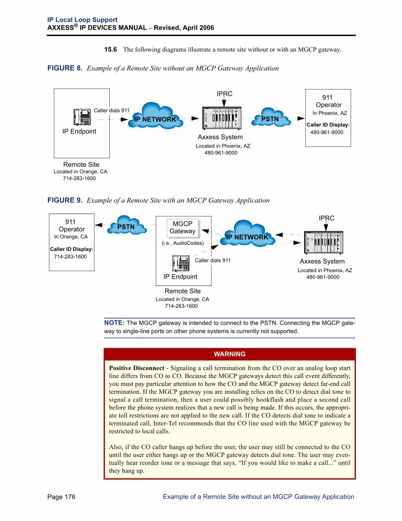
IP Local Loop SupportAXXESS® IP DEVICES MANUAL – Revised, April 2006
15.6 The following diagrams illustrate a remote site without or with an MGCP gateway.
FIGURE 8. Example of a Remote Site without an MGCP Gateway Application
FIGURE 9. Example of a Remote Site with an MGCP Gateway Application
NOTE: The MGCP gateway is intended to connect to the PSTN. Connecting the MGCP gate-way to single-line ports on other phone systems is currently not supported.
IPRC
Axxess System
PSTNIP NETWORK
IP Endpoint
911Operator
Located in Orange, CA
Caller ID Display:
714-283-1600
480-961-9000
Located in Phoenix, AZ480-961-9000
Remote Site
Caller dials 911 In Phoenix, AZ
IPRC
Axxess System
PSTNIP NETWORK
IP Endpoint
911Operator
Located in Orange, CA
Caller ID Display:
714-283-1600
714-283-1600
Located in Phoenix, AZ480-961-9000
Remote Site
MGCPGateway
(i.e., AudioCodes)
Caller dials 911
In Orange, CA
WARNING
Positive Disconnect - Signaling a call termination from the CO over an analog loop startline differs from CO to CO. Because the MGCP gateways detect this call event differently,you must pay particular attention to how the CO and the MGCP gateway detect far-end calltermination. If the MGCP gateway you are installing relies on the CO to detect dial tone tosignal a call termination, then a user could possibly hookflash and place a second callbefore the phone system realizes that a new call is being made. If this occurs, the appropri-ate toll restrictions are not applied to the new call. If the CO detects dial tone to indicate aterminated call, Inter-Tel recommends that the CO line used with the MGCP gateway berestricted to local calls.
Also, if the CO caller hangs up before the user, the user may still be connected to the COuntil the user either hangs up or the MGCP gateway detects dial tone. The user may even-tually hear reorder tone or a message that says, “If you would like to make a call...” untilthey hang up.
Page 176 Example of a Remote Site without an MGCP Gateway Application

IP Local Loop SupportAXXESS® IP DEVICES MANUAL – Revised, April 2006
A. SYSTEM DATABASE PROGRAMMING
15.7 The following describes the brief instructions on how to program an LSA in AxxessDatabase Programming.
NOTE: For information about how to program an MGCP gateway on an IPRC v8.2.x firmware,refer to the Addendum to the v8.0 Axxess Installation and Maintenance Manual.
1. Program the cabinet slot where the IPRC is installed as a DKSC-16.
NOTE: The “Amps Required” field will show that the card requires the 0.64 ampsneeded by a DKSC-16. However, an IPRC only requires 0.34 amps.
2. Program the port as Single-Port LSA (under System\Cabinets \Digital Keyset 16Card).
3. Program the following fields that are specific to IPRC LSA. Program rest of the fieldsas you normally program standard loop start trunks.
NOTE: Unless otherwise stated, all functionality of a standard loop start trunk is sup-ported with the LSA.
— Service Type: Call processing supports Caller ID on the LSA. The LSA has built-in Caller ID receivers and does not use shared Caller ID resources within the sys-tem. The resource manager within call processing is modified to have Caller IDreceivers as an attribute for this device type and to use the local Caller ID receiver.If the service type is set to Caller ID, Caller ID messages are passed up through theIPRC to call processing. By default, it is set to None.
NOTE: Caller ID receivers are not available on all MGCP gateways. Consult thedevice’s documentation for information on Caller ID support.
— DTMF Signaling: LSA trunks can be set for dual-tone multi frequency (DTMF)signals. The IPRC provides for several delivery methods of DTMF, call progresstone information, and audio. DTMF dialing can be done from anywhere, and thedigits will be correctly passed to the LSA (and vice versa). By default, it is set toYes.
NOTE: LSA timers and flags in Database Programming have no effect on the MGCP devices.Some of these settings can be directly programmed on the gateways. Consult the manuals pro-vided by the manufacturer for more information.
Page 177Example of a Remote Site with an MGCP Gateway Application

IP Local Loop SupportAXXESS® IP DEVICES MANUAL – Revised, April 2006
B. AUDIOCODES MP-100 MGCP GATEWAY
15.8 This section describes how to install and configure the AudioCodes MP-100 gateway,shown below.
15.9 AudioCodes MP-100 FXO gateway supports up to four loop start line (FXO) ports. Fordetails, refer to the MP-100 User’s Manual & Installation Guide.
Quick Start Installation Outline
15.10 The following steps outline the MP-100 installation. For details, refer to the pagesshown in parentheses in each step.
15.11 To install the MP-100:
1. Unpack the box, and set up the MP-100 gateway device through the AudioCodesBootP/TFTP Server program (see page 179).
2. Configure the MP-100 application through the AudioCodes MP-100 Web administrator(see page 184).
3. Verify that the Call Agent IP address in the MGCP Client Settings page is the IPRC IPaddress (see page 185).
4. Configure the IPRC ports through the IPRC Web page, and verify the following:
• The gateway is configured as an MGCP gateway and endpoint (the first circuit)and each additional endpoint is attached to the correct circuit. (See page 187.)
• All information is correct (MAC address, IP address, etc.). (See page 84).
• The connection is active in the Circuit Status page (see page 121).
15.12 The AudioCodes MP-100 Gateway is now ready for connection to the CO.
Page 178 AudioCodes MP-100 MGCP Gateway

IP Local Loop SupportAXXESS® IP DEVICES MANUAL – Revised, April 2006
Setting Up the MP-100
15.13 To set up the MP-100:
1. Create a new directory (e.g., Audiocodes MP_100) in the Windows Explorer on yourPC.
2. Detach and unpack the BootP and mp-100 zip files that were provided in the Inter-Tel AudioCodes MP-100 CD (part no. 827.9920) into this folder. You may want to cre-ate a subfolder for the BootP zip file within the same folder. The folder should looklike the one shown below.
3. Verify that you have the following files in the directory.
NOTE: The file names may be different depending on the version and date when thefiles were created.
• BOOT file (e.g., ramMP100.cmp) — Contains a compressed, downloadable soft-ware image file.
• INI file (e.g., mp100-2.ini) — Contains the default settings for the MP-100.
• Call Progress Tone file (e.g., CPUSA.dat or CPUUK.dat) — Contains all thetone and cadence definitions for US and European systems.
4. Open the mp100-2.ini file by using a word processor, such as Notepad, Microsoft®Word, etc. Add the IPRC IP address in the CallAgentIP field as shown below.
Call Agent IP
Page 179Setting Up the MP-100

IP Local Loop SupportAXXESS® IP DEVICES MANUAL – Revised, April 2006
5. If you are using Caller ID receivers, you must also manually add a caller ID definitionto the mp100-2.ini file. Enter CalleridTransportType = 3 at the end of the rowin the Channel Params field, as shown below.
6. Save and close the file.
7. Double-click on Setup.exe (in the BootP folder) to install the BootP Server.
8. Double-click on bootp.exe to launch the AudioCodes BootP/TPTF Server program.The following screen appears.
NOTE: Ensure the AudioCodes BootP/TFTP Server application is the only BootPserver running. If another server, such as the IPRC, is running at the same time, it maycause problems with the download.
New Definition for Caller ID
Page 180 Setting Up the MP-100

IP Local Loop SupportAXXESS® IP DEVICES MANUAL – Revised, April 2006
9. Select Preferences from the Edit menu. The following dialog box appears. Enter (orbrowse to) the directory path, where three MP-100 configuration files and BootP fileswere unpacked, in the Directory text box. Once the correct directory path is displayed,click OK. The dialog returns to the main screen.
10. Ensure the Dip Switch 3 in the up position and all others are down, as shown below.
Dip Switch
CONFIG
1 32 4 5
Page 181Setting Up the MP-100

IP Local Loop SupportAXXESS® IP DEVICES MANUAL – Revised, April 2006
11. In the main BootP/TPTF Server screen, select Clients from the Services menu or click. The following dialog appears. The Client Configuration dialog allows the client
(AudioCodes MP-100 gateway) to connect to the server application for code and con-figuration updates.
12. Click the Add New Client icon ( ). Highlight the desired client (if you have morethan one client) in the list on the left, and configure the settings as described below.
• Client MAC: Enter the MAC address, which can be found on the bottom of theMP-100 device.
• Client Name: Enter the desired name (e.g. mp100).
• Template: Select <none>.
• IP: Enter the IP address of the MP-100.
• Subnet: Enter the subnet mask of the MP-100.
• Gateway: Enter the gateway IP address of the MP-100.
• TFTP Server IP: Enter the TFTP Server IP address, if applicable.
• Boot File: Select ramMP100.cmp from the drop-down list.
• INI File: Select mp100-2.ini from the drop-down list.
• Call Agent: Enter the IPRC IP address.
13. Click Apply & Reset and close the Client Configuration dialog. Make sure the Pauseicon ( ) is not pressed in the main screen.
NOTE: If you have more than one AudioCodes MP-100 gateway, repeat steps 8 and 9.
Add New Client Icon
Page 182 Setting Up the MP-100

IP Local Loop SupportAXXESS® IP DEVICES MANUAL – Revised, April 2006
14. Attach up to four loop start lines to the RJ-11 connectors. The back view of an MP-100is shown below.
NOTE: Up to 200 m (660 ft) of 24AWG line cord can be used on loop start lines.
15. Attach the Ethernet cable to the ETH-1 RJ-45 connector to connect to your LAN. Todetermine the configuration of the MP-100, connect the DC power supply and observethe front panel LEDs. For more details on LED indicators, refer to the MP-100 User’sManual & Installation Guide.
16. The BootP status in the BootP/TFTP Server should show “Client Found” and “100%OK” on all three files. If not, there is a problem with the file location. Verify that thefile location is accurate and reconfigure the Client Configuration dialog, if necessary.
17. If the status is “100% OK,” then change the Dip Switch 3 to the down position.
15.14 Once the device is configured, the yellow lamps on the “Line” and “Tel” LEDs and thegreen lamps on the “Link” and “Ready” LEDs light. Follow the instructions on the followingpages to launch the MP-100 Web administrator and configure the application.
mp100-2.in.ramMP100...CPUSA.da...
Page 183Setting Up the MP-100

IP Local Loop SupportAXXESS® IP DEVICES MANUAL – Revised, April 2006
Configuring the MP-100
15.15 Once the BootP Client is set up, configure the MP-100 in the AudioCodes Web admin-istrator.
15.16 To configure the MP-100:
1. Open the Web browser and enter the IP address of your MP-100 gateway in the Addressfield. Then, press ENTER. The following home page appears.
NOTE: The IP address can be found in the IP field in the Client Configuration dialog,shown on page 182.
2. When the logon dialog box appears, enter the username and password. The default user-name is User and the password is 12345. If you are unable to login, verify that theClient Configuration is set up correctly (see page 182).
3. Click Configuration Menu. This menu has the following options. Click any of theoptions on the Web page and configure the settings as needed.
NOTE: Make sure the Call Agent IP address in the MGCP Client Settings matches theIPRC IP address (see page 185).
• Software Version: Make sure you have version number 3.80.024.0 or later.
• Network Settings: Select Network Settings from the Configuration Menu. Thefollowing page appears.
Page 184 Configuring the MP-100

IP Local Loop SupportAXXESS® IP DEVICES MANUAL – Revised, April 2006
— Base UDP Port: The base User Datagram Protocol (UDP) voice port is 4000.Do not change this number unless you are using other ports at or around thisnumber. Each voice channel or endpoint uses two UDP ports: one for Real-Time Transport Protocol (RTP) and one for Real-time Transport Control Proto-col (RTCP). Using lines 1 through 4 will use ports 4000 through 4050, inclu-sively.
— Default Gateway Address: If you need to change the subnet mask or gatewayaddress, it can be done here. Ensure these values match those on the IPRCDevice Configuration page (see page 93) if using static IP addressing.
— Board IP Address: Enter the IP address of the MP-100.— Board Subnet Mask: Enter the subnet mask of the MP-100.
• MGCP Client Settings: Select MGCP Client Settings from the ConfigurationMenu. The following page appears.
— Call Agent IP: Should match the IPRC IP address.— Call Agent Port: Should be set to 2427.— Call Agent Domain Name: Leave this field blank.— Redundant Agent IP: Should be set to 0.0.0.0.— Redundant Agent Port: Should be set to 2427.— Redundant Call Agent Domain Name: Leave this field blank. Inter-Tel cur-
rently does not support this feature.— Gateway Name: Enter the name you wish to identify this gateway with on the
network, such as MP100v1 (case-sensitive with no spaces or special charac-ters).
NOTE: With a v8.2.x firmware IPRC, ensure the names match those in AxxessDatabase Programming (under Sys tem\Cab ine ts \ IPRC (32-Device)\Devices\MGCP Gateway and Endpoint).
— Endpoint Name: The default endpoint name is ACgw (case-sensitive) andshould not be changed to avoid hostname resolution complications. Each end-point has a number appended to it. For example, line 1 is assigned the name“ACgw0,” line 2 is “ACgw1,” and line 4 is “ACgw3.”
NOTE: With a v1.5.x firmware IPRC, ensure the names match those on theMGCP Endpoint Name Settings page in the IPRC Web page. With a v8.2.xfirmware IPRC, ensure the names match those in Axxess Database Program-ming (under System\Cabinets\IPRC (32-Device)\Devices\MGCP Endpoint).
— MGCP Communication Layer Timeout: Should be set to 60 seconds.
192.168.0.1
MP100v1ACgw
Page 185Configuring the MP-100

IP Local Loop SupportAXXESS® IP DEVICES MANUAL – Revised, April 2006
• MGCP Channel Settings: Select MGCP Channel Settings from the Configu-ration Menu. The following dialog appears.
All settings, except the following, should remain as shown above. For more details,refer to the AudioCodes MP-100 User’s Manual.
— DTMF Transport Type: Should match the DTMF Encoding Setting (seepage 106) on the IPRC device page.
If G711 is selected in the Audio Settings page on the IPRC (see page 104), theDTMF Encoding Setting on the IPRC must be either None or Out-Of-Bandand the DTMF Transport Type must be set to Transparent.
If G729 is selected in the Audio Settings page on the IPRC (see page 104), theDTMF Encoding Setting on the IPRC must be Out-Of-Band and the DTMFTransport Type must be set to RFC2833 Relay DTMF.
NOTE: If G711 is selected in the Audio Settings page on the IPRC (seepage 104), all transport types (DTMF, MF, Fax, BELL Modem, and V21/22/23/32/34 Modem) must be set to Transparent. If G729 is selected on the IPRC,set the DTMF Transport Type to RFC2833 Relay DTMF and set the Fax Trans-port Type to Transparent.
— Fax/Modem Bypass Coder Type: Select G711MuLaw_64 for US systemsand G711ALaw_64 for European systems.
G711MuLaw_64
Page 186 Configuring the MP-100

IP Local Loop SupportAXXESS® IP DEVICES MANUAL – Revised, April 2006
Configuring the IPRC
15.17 Once the MP-100 is configured, configure the ports for the MP-100 in the IPRC Webpage.
15.18 To configure the ports:
1. Open the Web browser and enter the IP address of the IPRC in the Address field.
2. Press ENTER. The IPRC Administrative Session page appears (see page 84 for moredetails).
3. Select one of the following fields depending on how you want to setup the ports:
• Quick Setup — Device: Gives you step by step instructions on how to configurethe ports. This is the quickest method (see page 88 for details).
• Circuit Configuration — Device Type and Device Information: Allows you tomanually configure the ports (see pages 98 and 99 for details).
4. Select the port (a.k.a. circuit) to configure and follow the instructions below:
For port 1, select MGCP Gateway Device + Endpoint as the device type.
For ports 2, 3, and 4, select MGCP Add’l Endpoint as the device types.
NOTE: The same rule applies even when you have more than one gateway deviceinstalled in a network system. Configure the device type as MGCP GatewayDevice+Endpoint for port 1 and as MGCP Add’l Endpoint for ports 2-4.
Then follow the instructions on page 88 for the Quick Setup field or pages 98 and 99for the Circuit Configuration field.
5. Make sure the connection(s) are active in the Circuit Status page (see page 121).
15.19 The AudioCodes MP-100 Gateway is now ready for connection to the CO.
Page 187Configuring the IPRC

IP Local Loop SupportAXXESS® IP DEVICES MANUAL – Revised, April 2006
C. AUDIOCODES MP-104 MGCP GATEWAY
15.20 The AudioCodes MP-104 FXO MGCP gateway supports up to four loop start line(FXO) ports. Although the MP-104 is similar to the MP-100, each gateway uses a differentswitch type for configuring the device. The MP-100 uses DIP switches (see page 181), and theMP-104 uses a command-line switch (-fb). For details about command line switches, refer tothe MP-104 User’s Manual & Installation Guide.
15.21 The MP-104 on a v8.2.x or later IPRC firmware supports the peer-to-peer (P2P) audiofeature. This feature allows certain IP and SIP devices to transmit and receive audio directlywith each other. With this feature, the audio is not transmitted or received through the systemcabinet. This reduces delay and removes the audio stream from the Time Division Mulitplex(TDM) highway.
15.22 The MP-104 on a v8.2.x or later IPRC firmware does not support the following fea-tures:
• Tick Tone as an audio source for CO calls. This is normally used for features thatrequire audio sources, such as the Music-On-Hold feature.
• Pause digits. These digits are normally used to program a speed-dial or other digitstring.
NOTE: The MP-104 MGCP gateway must be running software version 4.2 or later when con-nected to an IPRC running version 8.2.x firmware.
15.23 For information about how to install and configure the AudioCodes MP-104 MGCPgateway, refer to the AudioCodes MP-104 Gateway Installation Guide (document part number835.2741)
Page 188 AudioCodes MP-104 MGCP Gateway

IP Local Loop SupportAXXESS® IP DEVICES MANUAL – Revised, April 2006
D. AUDIOCODES MP-104 SIP GATEWAY
15.24 With v9.0, the system supports SIP (Session Initiated Protocol) trunks to reach the CO.SIP trunks allow the system to communicate with the CO via SIP-enabled gateways. As theSIP protocol becomes more and more popular, it is important to be able to communicate to SIPgateways in the IP-centric world. Inter-Tel currently supports the AudioCodes MP-104 SIPgateway (with software version 4.2).
NOTE: Inter-Tel does not provide technical support for any SIP gateway other than the Audio-Codes MP-104 SIP gateway.
15.25 SIP trunks support the following functionality:• They are transparent to the system user because SIP trunks act like any other CO trunk
in the system.• They support transferring trunks, putting trunks on hold, and connecting trunks to con-
ferences similar to other CO trunks in the system.• They support making and receiving calls by any endpoint.• They support peer-to-peer audio by IP endpoints.• They reside in CO trunk groups just like other trunks so that SIP trunk calls can be
routed using Automatic Route Selection (ARS). • They support 911 calls just like MGCP trunks.
15.26 The MP-104 on a v8.2.x or later IPRC firmware does not support the following fea-tures:
• Pause digits. These digits are normally used to program a speed-dial or other digitstring.
• SIP registration which is used for authentication purposes.15.27 If you are updating an existing AudioCodes MP-104 MGCP gateway to support SIPtrunks, once the SIP software is installed you can no longer use MGCP. The MP-104 cannotsupport both MGCP and SIP simultaneously. To support MGCP, you must install the appropri-ate software using the BootP/TFTP process or by using the MP-104’s Web interface (seepage 58 for details).15.28 For information about how to install and configure the AudioCodes MP-104 SIP gate-way, refer to the AudioCodes MP-104 SIP Installation Guide (document part number835.2884)
Page 189AudioCodes MP-104 SIP Gateway

IP SoftphoneAXXESS® IP DEVICES MANUAL – Revised, April 2006
16. IP SOFTPHONE
16.1 The IP softphone is software that runs on your PC. The user interface is a virtual repre-sentation of an Executive or Professional endpoint, or IP PhonePlus. You can use it exactly asyou would the IP PhonePlus when connected to the IP card. You can also customize the dis-play by changing the fonts and colors. The available IP softphone are Axxess IP SoftPhone,Eclipse IP SoftPhone, and Model 8602. See below for illustrations and system requirements ofeach softphone. For installation and operation instructions, refer to the document provided withthe IP softphone.
A. AXXESS IP SOFTPHONE
16.2 Below is an illustration of the Axxess IP SoftPhone. The Axxess IP SoftPhone also hasoptional DSS maps with 20, 40, or 60 buttons.
16.3 Minimum PC requirements for IP SoftPhone are:
• For v1.101 - Microsoft Windows 98, 2000, NT, ME, and XPFor v1.003 - Microsoft Windows 95, 98, 2000, and NT
NOTE: IP SoftPhone v1.003 uses an older version of the Java Runtime Environment(JRE) which may not work properly with Intel® Pentium® 4 processors. If there is aproblem starting the application on a machine with a Pentium 4 processor, delete theSYMCJIT.DLL file from the JRE directory (e.g., C:\Program Files\JavaSoft\JRE\1.1\bin).
• IBM-compatible PC• Modem (56K or higher) or Ethernet Card• 200 MHz or faster microprocessor• 32 MB RAM• 20 MB available hard disk space• Network card with TCP\IP configured (or Dial-up Adapter via TCP\IP if via modem)• Full-duplex sound card• Headset with microphone (or speaker and microphone, but headset is recommended)
Page 190 IP Softphone

IP SoftphoneAXXESS® IP DEVICES MANUAL – Revised, April 2006
B. ECLIPSE IP SOFTPHONE16.4 Below is an illustration of the Eclipse IP SoftPhone.
16.5 Minimum PC requirements for IP SoftPhone v1.000 are:
• Microsoft Windows 95, 98, 2000, and NT• IBM-compatible PC• Modem (56K or higher) or Ethernet Card• 200 MHz or faster microprocessor• 32 MB RAM• 20 MB available hard disk space• Network card with TCP\IP configured (or Dial-up Adapter via TCP\IP if via modem)• Full-duplex sound card• USB or Parallel port (for security key)• Headset with microphone (or speaker and microphone, but headset is recommended)
Page 191Eclipse IP SoftPhone

IP SoftphoneAXXESS® IP DEVICES MANUAL – Revised, April 2006
C. MODEL 8602
The Model 8602 is a new Internet Protocol (IP) softphone that is used with the Inter-Tel®Axxess® Converged Communications Platform versions 9.1 and later. It requires IPRC firm-ware v9.0.0 or later. The Model 8602 is a softphone application that enables Voice over IP(VoIP) telephone calls from laptops or desktop computers. The Model 8602 connects to theInter-Tel® telephone system through an existing IP network. The Model 8602 operates like aModel 8662 endpoint and supports Inter-Tel Protocol (ITP) mode. After a connection is estab-lished, Model 8602 users can converse with the other party via a headset connected to their PC.Below is an illustration of the 8602 IP softphone.
Model 8602 has the following features:
• Integration with the Plantronics CS50-USB Wireless Headset
• Control and user-configurable options
• Control of audio and volume settings for the microphone and speaker
• Tray Client feature access
• Tray Client status indication
• Retractable dialpad
• User-friendly, modern look and feel
• Mouse and keyboard activated feature control
Like other endpoints, the IP softphone is identifiable in System Monitor and appears in:
• System Monitor dumps as an 890 device type
• Message Print as “IP Softphone Port”
Refer to the Model 8602 User Guide, part no. 835.3019, which provides the installation proce-dures for the Model 8602 and highlights the basic features for making and receiving calls andchecking voice mail messages. For more details on basic or advanced features of the Model8602, refer to the Model 8602 online help. Or, refer to the Inter-Tel Model 8662 User Guide(part no. 550.8117), which includes details of features not included in the Model 8602 UserGuide or online help. You can find this user guide on Inter-Tel’s Web site at www.inter-tel.com/techpublications.
Page 192 Model 8602

TroubleshootingAXXESS® IP DEVICES MANUAL – Revised, April 2006
17. TROUBLESHOOTING
17.1 This section provide troubleshooting procedures for the following categories:
• Connection issues (see page 193)
• Audio issues (see page 195)
• Echo issues (page 198)
• Multi-protocol endpoint issues (page 199)
• VLAN tagging issues (page 205)
A. CONNECTION ISSUES
Table 9: Connection Issues
SYMPTOM PROBABLE CAUSE CORRECTIVE ACTION
General connection issues
The Link LEDs are notlit
Verify the following settings:
• The Link LED is lit on the IP card and/or device.
• The Link LED is lit on the switch or hub to which these devices connect.
• The IP card or device has a unique IP address.
• You can ping the IP address from another PC on the same subnet.
• From the IP card's RS-232 or Telnet OLMN, you can ping the IP address of the problem device or IP card, and also you can ping in the other direc-tion from the problem device or IP card to the first card.
• Appropriate ports for IP devices and IP card are opened on a firewall, router, and/or NAT. To ver-ify the port connection, use the Port Test in the Network Qualifier software application.
Cannot connec t adevice to the IPRC
The endpoint does nothave the latest firmware
Verify the endpoint has the latest firmware by viewing the latest version in the endpoint Web interface. Refer to the Multi-Protocol Endpoint Firmware Compatibility Matrix on page 5.
The debug output is not normal
Check the debug output using RS-232 or Telnet (type msgp in the Debug Session) (see page 131). Normal output appears as follows:
<<UDP Broadcast Range/LAN ONLY>>Find server for 00:10:36:00:07:01 from 172.16.10.171:5567 -- port 13
<<UDP PART>>IP ID for 00:10:36:00:07:01 from 172.16.10.171:5567 -- port 13
<<TCP PART>>Connection from 172.16.10.171 on port 13
If the output is not normal, contact Inter-Tel Technical Support.
Page 193Troubleshooting

TroubleshootingAXXESS® IP DEVICES MANUAL – Revised, April 2006
(Continued) Cannot con-nect a device to the IPRC
Endpoint is not pro-grammed
Check the status in the Connected field in the Circuit Status page on the Web interface (see page 121) or the Network Status field in the Network Information on the Telnet (see page 131).
If the device is connected, but not operational, then it is a call processing problem. Verify that the System Database is programed as follows:
• The MAC address of the device is programmed in DB programming under System – Devices and Feature Codes – <endpoints>
• The card slot is programmed for DKSC16 (even for the 8-circuit IPCs).
• The circuit port is programmed for Keyset, Dual Single Line, or Single-Port LSA (requires sys-tem v7.0 or later).
• The call processing has the correct security PAL for the system.
If the device not connected, ensure the Device Type, Device ID, and/or Ethernet Address match the device. The following describes where the Ethernet address or device ID is located on each IP device type.
• IP PhonePlus displays its Ethernet address as it cycles through its power up screens.
• IP SLA has a sticker with the Ethernet address.
• IP SoftPhone controls the device ID under the settings option on startup.
• MGCP Gateway needs the device IP address, instead of the Ethernet address.
• MGCP endpoint needs the endpoint name, instead of the Ethernet address.
• Verify no network address translation is being used on the IP scheme (NAT/PAT).
Table 9: Connection Issues (Continued)
SYMPTOM PROBABLE CAUSE CORRECTIVE ACTION
Page 194 Connection Issues

TroubleshootingAXXESS® IP DEVICES MANUAL – Revised, April 2006
B. AUDIO ISSUES
Table 10: Audio Issues
SYMPTOM PROBABLE CAUSE CORRECTIVE ACTION
Audio quality is poor The network cannot sup-port VoIP calls.
Pre-Installation: Verify the network’s ability to support a VoIP call or calls using the Network Test in the Net-work Qualifier software application.
NOTE: The Network Qualifier requires a PC on each site. The PCs should not be used for any other pur-pose because other Windows applications could cause jitter.
Post-Installation: Verify the intime frames percentage using the Intime Packet Graph in the Receive Audio Status page (see page 119) on the Web interface. You can also watch live values through the Audio Receive Statistics on the Telnet interface. Be sure to watch the percentages on both the IP card and device. Note that the percentages will be quite low with Voice Activity Detection (VAD) enabled. These low values give some indication of the bandwidth saved by not transmitting silent audio packets.
An IP endpoint does not receive audio packets properly
Page 195Audio Issues

TroubleshootingAXXESS® IP DEVICES MANUAL – Revised, April 2006
Audio quality is poor (Continued)
Network related issues: there is heavy traffic con-tending for bandwidth, a hardware problem with switch or router, or defec-tive cabling.
To improve audio quality, try any of the following:
• Increase playback (jitter) buffer; however, adds delay or latency.
• Use G.729B (B = VAD); does not send silent packets.
• Increase Audio Frames/IP packet (see page 104) to reduce bandwidth needed; how-ever, increases latency.
• Use switches not hubs.
• Prioritize the packets through routers; most sim-ply prioritize the audio port (typically UDP 5004), but could also use DiffServ or TOS.
• Add more bandwidth.
• Paging and background music consume band-width; if a site has low bandwidth, they probably should not put all IP endpoints in the page zone.
• Do not use the hub or switch on the IP endpoint for a PC or other device that will consume a large amount of bandwidth in bursts or con-stantly.
Not enough bandwidth to support voice and data.
To test the best-case scenario:
• To eliminate any network problems, use a cross-over cable between an IPRC and an IP end-point, or simply plug the cable from the IP card into the hub on the endpoint. Remove the LAN cable from the IP endpoint’s power brick.
• Test a DKSC16 with a normal digital endpoint. If it sounds okay, then the backplane slot is okay; otherwise, switch slots.
Run the Network Qualifier to assess your bandwidth.
An IP endpoint lost audio suddenly while on a muted call
An IP endpoint lost back-ground music suddenly
IP endpoints are behind a firewall
When the Voice Activity Detection option (page 107) is enabled and if any IP endpoints are behind a firewall, the IP endpoints may suddenly lose audio (while on a muted call) or lose background music. If this occurs, disable the Voice Activity Detection flag. When the flag is enabled, the IP endpoint does not send silent audio packets to the IP card; however, the IP card continues to send non-silent audio packets to the IP endpoint. Eventually, most firewalls block this unsolicited IP audio stream from the IP card to the IP endpoint. (see page 13 for details about firewalls)
Table 10: Audio Issues (Continued)
SYMPTOM PROBABLE CAUSE CORRECTIVE ACTION
Page 196 Audio Issues

TroubleshootingAXXESS® IP DEVICES MANUAL – Revised, April 2006
A call was established between two IP end-points, but there is no audio.
The IP endpoints are programmed for P2P audio, but they do not support the same vocoder.
Remove the IP devices from the Network Group. Consider adding them to a Network Group that con-tains IP devices that support the vocoder.
The IP endpoints are programmed for P2P audio, but they do not support the same num-ber of audio frames per IP packet.
Remove the IP devices from the Network Group. Consider adding them to a Network Group that con-tains IP devices that support the same number of audio frames per IP packet.
There is a firewall or NAT between the two devices.
Place the devices into different Network Groups or disable the Use Peer-To-Peer Audio flag for the group.
Make sure the correct IP ports are open. Refer to the PROGRAMMING or the Web interface for the current available ports that can be used,
Run Network Qualifier to test the ports to make sure they are not blocked.
The endpoint received the following alarm: A032 ALARM Ext. <xxxx> Received Insuf-ficient Bandwidth.
The IPRC [b.p.d] detected that the audio-receive timer has expired without receiv-ing the first audio packet or the average-in-time-frame percent-age has fallen below the threshold specified in the Voice Audio Session Configure Command.
This indicates a network problem. Poor network con-dition could cause packet loss or a firewall prevents the callers to receive audio packets. There is a sys-tem flag that can disable this alarm.
The “Insufficient Bandwidth” alarm is displayed when the average number of In Time frames falls below the Average In Time Frame Percentage Threshold (in System\IP-Related Information\Call Configura-tion), and the average number of In Time frames stays below that threshold for the time given by the Average In Time Frame Timer (in seconds) in Sys-tem\IP-Related Information\Call Configuration. To change the percentage, click the current Value and use the scroll box to select the new value. Then press ENTER or click another field to save the change. The range for Average In Time Frame Per-centage Threshold is 0-100%, and the default is 60%. The range for Average In Time Frame Timer is 0-255 seconds, and the default is 5 seconds.
Table 10: Audio Issues (Continued)
SYMPTOM PROBABLE CAUSE CORRECTIVE ACTION
Page 197Audio Issues

TroubleshootingAXXESS® IP DEVICES MANUAL – Revised, April 2006
C. ECHO ISSUES
Table 11: Echo Issues
SYMPTOM PROBABLE CAUSE CORRECTIVE ACTION
IP endpoint users hear echo on their endpoint while talking to an analog trunk (like SLC, SLA, or trunk)
Hybrid balance is not on the correct setting
To reduce echo, first test echo and verify the following settings. Then, follow the instructions on the following page.
NOTE: When testing echo, make sure you dial the same phone number using the same trunk. Seize the trunk directly, and do not use the trunk group or ARS. Different trunks have different characteristics.
Verify the hybrid balance setting. If the trunk does not connect to a public CO, or if the CO is relatively close, then the hybrid balance should be set to “Short.” No matter what the current setting is, try the other setting and dial the same number through the same trunk. One setting should be dramatically worse than the other. You should disable the Echo Suppression option (see page 107) so you can actually hear the echo from the beginning of the call, or use the Echo Canceller Statistics (see page 132) on Telnet to mea-sure the echo. Refer to the Echo Troubleshooting Guide (document part no. 835.2844) that is located on the Inter-Tel edGe at www.inter-tel.com/techpublica-tions.
The audio volume for the IP device is too high
To reduce echo from an analog circuit, reduce the audio volume the IP card drives on to the backplane. This will help the echo canceller adapt quicker. Follow the instructions below:
1. Adjust the Backplane Transmit Signal Gain option (see page 95) on the Web interface. The default setting is 0dB (without any reduction). Any change you make will reduce the volume.
2. After the adjustment, dial the same number through the same trunk. You should disable the Echo Suppression option (see page 107) so you can actually hear the echo from the beginning of the call. The side effect is that the person on the other end of the call may have a hard time hearing the IP user because the volume is reduced.
Page 198 Echo Issues

TroubleshootingAXXESS® IP DEVICES MANUAL – Revised, April 2006
D. MULTI-PROTOCOL ENDPOINT-RELATED ISSUES
IP endpoint users hear echo on their endpoint while on a digital trunk
The echo canceller is designed to cancel echo from the cabinet, not the echo from the CO because it takes too long for echo to return to IP card.
In an attempt to reduce echo from a digital CO trunk, do any of the following:
• Reduce T1 gain on Transmit to CO if your sys-tem supports it.
• Reduce T1 gain on Receive from CO if the echo is quite low in volume and if your system sup-ports it.
NOTE: System v5.1 or later is required to sup-port T1/E1 or T1/E1/PRI gain control. Reducing T1 gain will affect all users, not just the VoIP users.
• Adjust the Backplane Transmit Signal Gain option (see page 95) on the Web interface, as described above in the troubleshooting for ana-log circuits. The Backplane Transmit Signal Gain setting can be applied to T1 or any circuit, not just analog circuits.
IP users hear a low-vol-ume, clean, clear echo during the beginning of the audio session
Echo Suppression Sensi-tivity Level is not bal-anced
Enable the Echo Suppression option (see page 108). With this option enabled, adjust the Echo Suppression Sensitivity Level during the beginning of an audio ses-sion to find the balance between the IP user hearing a slight echo and hearing a half-duplex condition on the handset. The Echo Suppression Sensitivity Level does nothing if the Echo Suppression is disabled. Dis-able the Echo Suppression when using the circuit for fax operations or as a last resort to eliminate the half-duplex condition on the handset during the beginning of the audio session.
An IP user hears raspy or distorted echo as he speaks quite loudly or holds the handset close to his mouth
The Echo Saturation Blocker option is not enabled
Enable the Echo Saturation Blocker option (see page 109).
An IP user hears choppi-ness or a half-duplex con-dition on the handset as she speaks quite loudly or holds the handset close to her mouth
The Echo Saturation Blocker option is enabled
Disable the Echo Saturation Blocker option (see page 109).
Table 11: Echo Issues (Continued)
SYMPTOM PROBABLE CAUSE CORRECTIVE ACTION (Continued)
Page 199Echo Issues

TroubleshootingAXXESS® IP DEVICES MANUAL – Revised, April 2006
Table 12: Multi-Protocol Endpoint-Related Issues
SYMPTOM PROBABLE CAUSE CORRECTIVE ACTION
The multi-protocol end-point powers up and all the lamps remain lit per-manently.
The endpoint software is corrupt
The voice processing software is corrupt, and the multi-protocol endpoint must be recovered using the follow-ing steps:
1. Set up a PC on the same LAN as the endpoint.
2. Make sure the PC has a TFTP server and the cor-rect software image file.
3. Rename the software image from 86xx_x_x_x.bin (where the _x_x_x represents the version number) to 86xx.bin. For example:
— Rename 8600_1_1_5.bin to 8600.bin
— Rename 8620_1_1_5.bin to 8620.bin (note that the Models 8620 and 8622 share the same binary image)
— Rename 8662_1_1_5.bin to 8662.bin (note that the Models 8622 and 8622 share the same binary image)
— Rename 8690_1_1_5.bin to 8690.bin
4. Point the TFTP server at the directory that contains this software image file.
5. Configure the IP address of the PC as 192.168.200.202. The endpoint starts pulling this file from the TFTP server. When finished, the endpoint resets on its own.
The Model 8622 or 8662 endpoints are not upload-ing new firmware images as specified in the TFTP configuration files.
OR
The TFTP configuration files have been modified with new image versions, but the Model 8622 or 8662 endpoints have not uploaded the new firm-ware.
The image strings have not been updated
Make sure that these strings have been updated. For example,
From 1.1.5 and earlier to 2.0.06:
86xx_image_ver: HWID 2.0.06
86xx_image_url: 192.168.200.202/86xx/86xx_2_0_06.bin
NOTE: If upgrading an 8622 from 1.01S to 1.1.5, usethe following image version string: 8620_image_ver:8620 HWID 1 1.1.5.
For future releases (2.0 and later):
itphone_image_ver: 2.0.06
itphone_image_url: 192.168.200.202/itphone/itphone_2_0_06.bin
The endpoint may have background music enabled
Turn off the background music feature (default feature code: 313).
Page 200 Multi-Protocol Endpoint-Related Issues

TroubleshootingAXXESS® IP DEVICES MANUAL – Revised, April 2006
While installing the client application on the Model 8690, an error message indicating that the setup failed appears.
The endpoint does not have sufficient memory resources or the endpoint has lost power before the upgrade is complete
The client application installation on the Model 8690 has failed. You must reformat the flash file system on the endpoint. See page 172 for details.
The Windows CE.Net stops during the firmware upgrade.
This may be caused by using most of the system resources (processor and RAM) during an upgrade.
Try doing one of the following:
• Restart the Windows CE upgrade by going into Pending Upgrades. Windows CE will still show up as “Pending” because it has not completed copy-ing, which results in a reset of the Model 8690. Press “OK” to restart the upgrade and eventually this causes the original upgrade time out and dis-play the dialog box to restart that upgrade. Press “No” to cancel the original upgrade and continue with the second download that is in progress (usually still erasing flash at this point).
• Launch the 8690 manually by using a USB mouse. The USB mouse does not require a lot of memory in the CPU. With the USB mouse attached the user can perform some basic func-tions and still see the Model 8690 endpoint responding. The mouse should be attached before the upgrade is started.
NOTE: When an upgrade is in progress, avoid using the Model 8690 endpoint.
The Model 8622 or 8662 endpoint flashes the error message “ERROR WRONG HWID” when attempting to download a new image.
The image that the Model 8622 or 8662 endpoint is attempting to download does not support the end-point’s hardware.
Use a more recent image, preferably at or above the version shipped with the endpoint.
A multi-protocol endpoint flashes the error message “ERROR WRONG VER-SION” when attempting to download a new image.
The version number in the xxxx_image_ver string may not match up with the image’s version.
Correct the xxxx_image_ver image version number or the image name (if pointing at the wrong image file).
Table 12: Multi-Protocol Endpoint-Related Issues (Continued)
SYMPTOM PROBABLE CAUSE CORRECTIVE ACTION
Page 201Multi-Protocol Endpoint-Related Issues

TroubleshootingAXXESS® IP DEVICES MANUAL – Revised, April 2006
The Model 8622 endpoint flashes the error message “ERROR WRONG VER-SION” when attempting to download a new image.
The endpoint does not have the latest firmware
The Model 8622 endpoints running firmware version 1.01S will display the error “ERROR WRONG VER-SION” when attempting to download new firmware. To upload the new firmware to the 8622, first use one of the following version strings to upgrade to either ver-sions 1.0.33 or 1.1.5:
8620_image_ver: 8620 1.0.33
or
8620_image_ver: 8620 HWID 1 1.1.5
Once the newer firmware has been loaded on the Model 8622 endpoint, change the image version string back to one of the following:
8620_image_ver: 1.0.33
or
8620_image_ver: HWID 1 1.1.5
or
itphone_image_ver: 2.v.vv (the v.vv indicates the firmware version, such as 2.0.06)
NOTE: After the firmware has been upgraded, the endpoint will again display the error “ERROR WRONG VERSION” every time it attempts to upgrade until the configuration version line is returned to the normal state noted above in either the TFTP file or the Web page (i.e., “8620_image_ver: 1.0.33”).
Table 12: Multi-Protocol Endpoint-Related Issues (Continued)
SYMPTOM PROBABLE CAUSE CORRECTIVE ACTION
Page 202 Multi-Protocol Endpoint-Related Issues

TroubleshootingAXXESS® IP DEVICES MANUAL – Revised, April 2006
When the multi-protocol endpoints reset, network connectively on the down-link (i.e., the LAN port labeled “PC” on the back on the endpoint) is tem-porarily lost.
The endpoints generally reset for one of the follow-ing reasons:
(1) Endpoint setting or firmware updates - the endpoints may require a reset for certain configu-ration changes to take place and will reset if the firmware is updated.
(2) Telephony system updates - the endpoints will reset when the Call Processing system dis-connects their connection for updates on the Call Processing side. The end-point will continue to reset every several minutes until the telephony system recovers and the endpoint can re-connect.
(3) Loss of network con-nectivity - the endpoints will reset when network congestion or loss of net-work connectivity pre-vents necessary keep-alive packets from being exchanged between Call Processing and the end-point.
Work-arounds for this issue are as follows:
• Minimize endpoint resets due to system updates - Schedule telephony system and endpoint updates for non-peak hours when endpoint and network connectivity outages are less service affecting.
• Isolate and eliminate any network issues - Isolate and eliminate any network congestion issues that may cause the endpoint to lose communication with Call Processing and thus reset.
• For critical applications that cannot tolerate any interruptions in LAN service, use an external switch in place of the downlink port for network connectivity until resets due to external factors can be minimized.
In the case of (3) loss of network connectivity, make sure that the network in question meets the minimum requirements specified in the Inter-Tel’s VoIP Data Net-work Requirements (document part no. 835.2885). This document can be found on the Inter-Tel eDge Web site, under Online Manuals & Guides – IP Telephony Online Manuals (www.inter-tel.com/techpublications).
Table 12: Multi-Protocol Endpoint-Related Issues (Continued)
SYMPTOM PROBABLE CAUSE CORRECTIVE ACTION
Page 203Multi-Protocol Endpoint-Related Issues

TroubleshootingAXXESS® IP DEVICES MANUAL – Revised, April 2006
The HP (Hewlett-Pack-ard) POE (Power over Ethernet) network appli-ances may cause an issue with the Inter-Tel IP endpoints (Models 8600, 8620, 8622 or 8662) where the endpoint will fail to activate (power up).
The HP POE equipment is influencing the pins 4,5, 7 and 8 when applying power on pins 1, 2, 3 and 6 thus preventing the Inter-Tel endpoint from working.
Note: The HP POE net-work appliances provide power via pins 1,2, 3 and 6 and this is Alternative (A) wiring according to 802.3af. All IP end-points must support Alter-native (A) or (B) power on either pins 1,2,3 and 6 or 4, 5, 7 and 8 per 802.3af. But only one set of 4 leads can be used at any time.
If using an HP POE network appliance with the Inter-Tel endpoints remove the unused set of power leads 4, 5, 7 and 8 by un-terminating them for each endpoint or pur-chase network splitters that split 1,2,3 and 6 from 4, 5, 7 and 8. These are available through Inter-Tel’s Com-mSource or Telecom suppliers. The following are the pin outs for Power over Ethernet.
Inter-Tel’s Hardware engineering is continuing to work with Hewlett-Packard on a long-term solution. Once this is completed this information will be updated.
Table 12: Multi-Protocol Endpoint-Related Issues (Continued)
SYMPTOM PROBABLE CAUSE CORRECTIVE ACTION
Con-ductor
Alternative A (MDI-X)
Alternative A (MDI)
Alternative B (All)
1 Negative V Port
Positive V Port
2 Negative V Port
Positive V Port
3 Positive V Port
Negative V Port
4 Positive V Port
5 Positive V Port
6 Positive V Port
Negative V Port
7 Negative V Port
8 Negative V Port
Page 204 Multi-Protocol Endpoint-Related Issues

TroubleshootingAXXESS® IP DEVICES MANUAL – Revised, April 2006
E. VLAN TAGGING-RELATED ISSUES
F. IPRC DIAGNOSTICS17.2 The IPRC v7.0 or later firmware has many diagnostic tools used for troubleshootingpurposes. These tools are separate from Call Processing and display only information local tothe IPRC. There are also limited programming displays to control the card. For details aboutdiagnostics information, refer to the TROUBLESHOOTING section in the Inter-Tel AxxessInstallation and Maintenance Manual (document part no. 550.8000).
Table 13: VLAN Tagging-Related Issues
SYMPTOM PROBABLE CAUSE CORRECTIVE ACTION
The user cannot connect to the Web interface for a multi-protocol endpoint.
The PC that the user uses may not be in the same VLAN group as the endpoint.
The PC that the user uses may not be in the same VLAN group as the endpoint. Make sure that the PC and endpoint are in the same VLAN group. If not, set the endpoint VLAN ID to match the PC or disable the VLAN feature for the endpoint (see page 23).
The user cannot connect to the Model 8690 Web interface but could con-nect to the Model 8622 or 8662 Web interface. The VLAN ID of the phone port is disabled but the VLAN ID of the downlink port is enabled (not zero).
The VLAN ID of the end-point is disabled
This is a limitation of the 8690 internal phone Ethernet switch. The 8690 Ethernet switch inserts the default VLAN ID which is 1 if the frames from the endpoint are untagged.
Connect the PC to one of the downlink ports which has VLAN ID set to zero.
The user powers up the endpoint with the correct VLAN ID, but the end-point receives the wrong IP settings from the wrong DHCP from another VLAN.
The network switch may not support VLAN or wrong VLAN ID is pro-grammed at the switch port of the core switch network.
Make sure that the core network switch is programmed correctly.
The user powers up 8690 but the network settings still show the settings with the old VLAN values.
The endpoint application may not be updated so the new VLAN settings may not have been prop-agated to the VPS. If the endpoint application is up to date, then the new VLAN IDs may not have been sent down to the VPS in time.
Make sure that the endpoint application is up to date, and reset the endpoint after the VLAN ID in the phone port has been changed from the networking control panel of Windows CE.
Page 205VLAN Tagging-Related Issues

Part NumbersAXXESS® IP DEVICES MANUAL – Revised, April 2006
18. PART NUMBERS
18.1 The part numbers associated with IP cards and IP devices are listed in the followingtable.
DESCRIPTION PART NUMBER
Devices
IP Resource Card (IPRC) 550.2265
Axxess IP PhonePlus with 10Base-T Hub 770.4500
Eclipse IP PhonePlus with 10Base-T Hub 560.4401
Model 8660 550.8660
Model 8664 Wireless IP Endpoint 550.8664
Model 8665 Wireless IP Endpoint 550.8665
Model 8600 Multi-Protocol Endpoint 550.8600
Model 8620 550.8620
Model 8622 550.8622
Model 8662 550.8662 (8 MB)550.8662E (16 MB)
Model 8690 550.8690
Model 8601 SoftPhone for Pocket PC 827.9901
IP Single-Line Adapter 770.3000
MP-100 MGCP Gateway 4-Port FXO 901.3915
MP-104 MGCP Gateway 4-Port FXO 901.3916
Device IPRC PALs
8-Port Station PAL for IPRC 827.9449
16-Port Station PAL for IPRC 827.9450
IPRC PAL Upgrade 828.1637
32-Device IPRC Software License
Category A Endpoint License: 8 Ports 840.0132
Category A Endpoint License: 16 Ports 840.0133
Category A Endpoint License: 32 Ports 840.0134
Category B Endpoint License (for the Model 8602) 840.0633
IP Networking Ports: 4 Ports 840.0115
IP Networking Ports: 8 Ports 840.0116
IP Networking Ports: 16 Ports 840.0117
IP Networking Ports: 32 Ports 840.0118
Power Supply Parts
US Power Supply — AC Input: 120V 0.2A, DC Output: 24V 0.5A 806.1113
US Power Supply — AC Input: 120V 0.12A, DC Output: 48V 0.15A 806.1114
UK Power Supply — AC Input: 240V 0.12A, DC Output: 48V 0.15A 806.1117
Page 206 Part Numbers

Part NumbersAXXESS® IP DEVICES MANUAL – Revised, April 2006
UK Power Supply — AC Input: 240V 0.12A, DC Output: 24V 0.5A 806.1118
Universal Power Supply — AC Input: 100-240V 1.2A, DC Output: 24V 1.0A
806.1119
Red Hawk PowerSense Single-Port Module for Multi-port Hub (24V Protocol)
901.0403
Red Hawk PowerSense Single-Port Module for Multi-port Hub (IEEE 802.3af Protocol)
901.0404
Red Hawk PowerSense Single-Port Module (24V Protocol) 901.0406
Red Hawk PowerSense Single-Port Module (IEEE 802.3af Protocol) 901.0407
US Power Supply Kit - US power supply (P/N 806.1113)- Network cable (P/N 813.1790)
828.1642
Universal Power Supply Kit - Universal power supply (P/N 806.1119)- Network cable (P/N 813.1790)
828.1660
System Software
AudioCodes MP-100/104 CD-ROM 827.9920
IP Devices CD-ROM 827.9162
Documentation
Inter-Tel Axxess Installation Maintenance Manual 550.8000
Addendum to Issue 8.0 of the Inter-Tel Axxess Installation and Mainte-nance Manual
550.8023
Model 8690 Administrator’s Guide 550.8120
Multi-Protocol Endpoints: Supported Features, Buttons, and LED Indi-cations
835.2840
SIP Server Installation and Configuration Manual 835.2605
Model 8601 SoftPhone for Pocket PC Installation Manual 835.2736
NetLink SVP Server and Model 8664/8665 Installation Manual 935.4521
Red Hawk PowerSense Power over Ethernet Installation Manual 935.0400
AudioCodes MP-104 Quick Start Guide 835.2740
DESCRIPTION (Continued) PART NUMBER
Page 207Part Numbers

FCC InformationAXXESS® IP DEVICES MANUAL – Revised, April 2006
19. FCC INFORMATION
19.1 The IP SLA complies with UL1950/CSA950 and EN 60950 standards and complieswith EN 55022 and Part 15 of the FCC Rules.19.2 The IP PhonePlus has a hearing-aid compatible handset that is in compliance with sec-tion 68.316 of the FCC Rules.19.3 The IP devices comply with Part 15 of the FCC Rules. Operation is subject to the fol-lowing two conditions:
• This device may not cause harmful interference.
• This device must accept any interference received, including interference that maycause undesired operation.
19.4 The AudioCodes MP-100 and MP-104 FXO comply with Part 68 of the FCC Rules.
19.5 For further FCC information, refer to the Inter-Tel Axxess Installation and MaintenanceManual (document part no. 550.8000).
20. GLOSSARY
• BOOTP (Bootstrap Protocol): A protocol that lets a network user be automaticallyconfigured (receive an IP address) and have an operating system booted or initiatedwithout user involvement.
• Circuit: Crosspoint connection on the IPRC.
• Cookie: Refers to the state information that passes between a Web server and useragent (Web client). This information is stored by the user agent.
• DHCP (Dynamic Host Configuration Protocol): Allows a network administrator tosupervise and distribute IP addresses from a central point and automatically send a newIP address when a computer is plugged into a different place in the network.
• Firewall: A set of related programs, located at a network gateway server, that protectsthe resources of a private network from users on other networks.
• Frame Relay: A telecommunication service designed for cost-efficient data transmis-sion for intermittent traffic between local area networks (LANs) and end-points in awide area network (WAN).
• Gateway: A network point that acts as an entrance to another network.
• IE: Microsoft Internet Explorer.
• IP (Internet Protocol): The method or protocol by which data is sent from one com-puter to another on the Internet.
• IPT (Internet Protocol Terminal): IP PhonePlus or Model 8660 endpoint (IP Phone-Plus), IP Single-Line Adapter (IPSLA), or IP SoftPhone (IPSOFT).
• LAN (Local Area Network): A network of interconnected workstations sharing theresources of a single processor or server within a relatively small geographic area.
• MGCP (Media Gateway Control Protocol): A protocol for controlling telephonygateways from external call control elements called media gateway controllers or callagents.
• MGCP Gateway: Network device that provides conversion between the audio signalscarried on telephone circuits and data packets carried over the Internet or over otherpacket networks using MGCP.
Page 208 FCC Information

GlossaryAXXESS® IP DEVICES MANUAL – Revised, April 2006
• MGCP Gateway Endpoint: MGCP endpoints are physical/virtual sources or sinks ofdata that reside in an MGCP gateway.
• NAT (Network Address Translation): The translation of an Internet Protocol address(IP address) used within one network to a different IP address known within anothernetwork.
• Network: A series of points or nodes interconnected by communication paths.
• OLMN: Online Monitor.
• Ports: A port number is a way to identify a specific process to which an Internet orother network message is to be forwarded when it arrives at a server.
• Packet: A packet is the unit of data that is routed between an origin and a destinationon the Internet or an any other packet-switched network.
• Proxy Server: A server that acts as an intermediary device between a workstation userand the Internet to ensure security, administrative control, and caching service capabili-ties. A proxy server is associated with or is part of a gateway server that separates theenterprise network from the outside network and a firewall server that protects theenterprise network from outside intrusion.
• Router: A device or, in some cases, software in a computer that determines the nextnetwork point to which a packet should be forwarded toward its destination. The routeris connected to at least two networks and decides which way to send each informationpacket based on its current understanding of the state of the networks to which it is con-nected. A router is located at any juncture of networks. A router is often included aspart of a network switch.
• RTP (Real-time Transport Protocol): A protocol that ships real-time packets, such asvoice packets, from one endpoint to another endpoint.
• SIP (Session Initiation Protocol): A text-based, standards protocol, similar to HyperText Transfer Protocol (HTTP) and Simple Mail Transfer Protocol (SMTP).
• Subnet: An identifiably separate part of an organization’s network. Typically, a subnetmay represent all of the machines at one geographic location, in one building, or on thesame local area network (LAN).
• TCP (Transmission Control Protocol): A method used along with the Internet Proto-col (IP) to send data in the form of message units between computers over the Internet.
• UDP (User Datagram Protocol): A communications method that offers a limitedamount of service when messages are exchanged between computers in a network thatuses the Internet. UDP is an alternative to the Transmission Control Protocol (TCP). Italso provides port numbers to help distinguish different user requests.
• WAN (Wide Area Network): A geographically dispersed telecommunications net-work, distinguishing a broader telecommunication structure from a local area network(LAN).
Page 209Glossary

GlossaryAXXESS® IP DEVICES MANUAL – Revised, April 2006
Page 210 Glossary

IndexAXXESS® IP DEVICES MANUAL – Revised, April 2006
IndexNumerics
0 14410/100 Switch
default switch 128program switch 127
10/100 Switch — Default Switch 12810/100 Switch — Program Switch 12710Base-T Module 33, 3416 MB RAM, 4 MB flash memory, enhanced 516 MB RAM, 4 MB flash memory, enhanced, redesigned 516 MB RAM, 4 MB flash memory, noise-reduced 516 MB RAM, 4 MB flash memory, original 516-Port Station PAL for IPRC 20632-Device IPRC Software License 2068 MB RAM, 2 MB flash memory, original 58 MB RAM, 4 MB flash memory, original 58690 Client Application 1738-Port Station PAL for IPRC 206
A
ADDRESS 51Address 51ADDRESS AT 51Advanced Audio Settings 114Advanced Network Configuration 113Application Name 155Application Programming 20Audio & Call Control 148
card configuration 95circuit configuration 101device configuration 103
Audio Channel 120Audio Frames per IP Packet 10Audio Frames/IP Packet 96, 104, 113, 136, 149Audio Frames/IP Packet (3) 104, 113Audio Frames/IP Packet (Default) 96Audio Issues 195Audio Port 149Audio Quality 196Audio quality is poor 195Audio quality is poor (Continued) 196Audio Settings 113, 164Audio Stream 96
receive port 95, 96, 133, 149send port 96, 104, 113, 135transmit IP address 149transmit port 149
Audio Stream Receive Port 149Audio Stream Receive Port (5004) 95, 133Audio Stream Send Port (5004) 104, 113, 135Audio Stream Send/Receive Port (5004) 96Audio Stream Transmit IP Address 149Audio Stream Transmit Port 149AudioCodes
configuration 184gateway device 178, 188, 189MP-100 175MP-100/104 CD-ROM 207MP-104 188, 189
AudioCodes MP-100 Gateway 178AudioCodes MP-100 MGCP Gateway 178AudioCodes MP-100/104 CD-ROM 207AudioCodes MP-104 Gateway 188, 189AudioCodes MP-104 MGCP Gateway 188AudioCodes MP-104 Quick Start Guide 207AudioCodes MP-104 SIP Gateway 189Automated Boot Code Update 72Average Network Jitter 120Average Network Jitter (ms) (0) 120Awaiting Download 49Axxess Database Programming 167Axxess Database Programming in ITP mode 167Axxess IP PhonePlus 44
with 10Base-T hub 206Axxess IP PhonePlus with 10Base-T Hub 206Axxess IP SoftPhone 190
B
Backplanecompanding type 96transmit signal gain 95
Backplane Companding Type(Mu-Law) 96Backplane Transmit Signal Gain (0dB) 95Bandwidth Utilization 8Barrel Jack 34Base UDP Port 185Board
IP address 185subnet mask 185
Boot Code Date/Time 155Boot Code Download Progress Displays 72Boot Code Version 155Boot File 182Boot Image Changes 72BOOTP 82, 100
Client IP Address 101, 113client IP address 113IP Address 135IP address 135
BOOTP (Enabled) 100BOOTP Client IP Address (0.0.0.0) 101, 113BOOTP IP Address (0.0.0.0) 135BOOTP? 82Burst Rate (BR) 7
C
Calculationslatency 10voice over IP 8VoIP across frame relay 9
Call Agentdomain name 185
Page 211

IndexAXXESS® IP DEVICES MANUAL – Revised, April 2006
IP 185IP address 182
Call Control 112CALL PROCESSING/ 51Card or Device Configuration
audio & call control 95change login password 97network 93
Card or Device Configuration — Audio & Call Control 95Card or Device Configuration — Change Login Password 97Card or Device Configuration — Network 93Card Slot 121Card Slot (Unknown) 121CF (Compact Flash) 39CHANGE CASE 143Change Login Password 97Changes and New Features 3CIR (Committed Information Rate) 7Circuit 98, 99, 100, 101, 103, 104, 106, 110, 120, 121, 123Circuit (or Audio Channel) 120Circuit Configuration
circuit login password 106device information 98device specific 111network 100
Circuit Configuration — Advanced Audio Settings 106Circuit Configuration — Advanced Network 101Circuit Configuration — Audio Settings 104Circuit Configuration — Call Control 103Circuit Configuration — Device Information 99Circuit Configuration — Device Login Password 110Circuit Configuration — Device Specific 111Circuit Configuration — Device Type 98Circuit Configuration — Network 100Client
MAC 182name 182
Codec Type 149Command 157
configuration 157download 125reset 122, 157reset circuits 123
Command — Download 125Command — Reset 122Command — Reset Circuits 123Committed Information Rate (CIR) 7Compact Flash (CF) 39Completed State 49Computer Science Roots 4Configuration 157Configuration Files 66Configuration Image Version 157Configuration Parameters
audio settings 164ITP mode settings 161network settings 159SIP mode settings 162SIP settings 163
Configuring the IPRC 187Configuring the MP-100 184Confirm New Login Password 110
Confiuring Phone Ports for a VLAN 174Connected (NO) 121Connecting
the IP device 92to the IPRC 50
CONNECTING TO 50
Connection Issues 193CONTACT IP CARD 51COULD NOT 51COUNT NOT 51Country 96, 109, 117Country (US) 96, 109, 117
D
Databasedefault 126programming 131restore 126save 125
Database — Default 126Database — Restore 126Database — Save 125Date/Time 155DBDS (Database Device Specific) 138DBMN (Database Main Entries) 138Default
database 83, 126, 144database and exit 83, 144gateway 82, 143gateway address 185IP gateway 86, 89IP gateway address 93, 100, 112, 147network subnet mask 93, 100, 112, 147
Default Database and Exit 83, 144DEFAULT GATEWAY 82, 143Default Gateway 155Default IP Gateway (0.0.0.0) 86, 89Default IP Gateway Address 147Default IP Gateway Address (0.0.0.0) 93, 100, 112Default Network Subnet Mask 147Default Network Subnet Mask (0.0.0.0) 93, 100, 112Description 120, 121Determine the IP address of a Model 8600 67Device
description 98, 99, 100, 101, 103, 104, 106, 110, 111, 123, 136flags 136, 137, 139, 140hostname 140ID 99, 112, 121, 123information 98, 99, 111IP address 123IPRC PALs 206number 111, 135password 136, 138quick setup 88specific 111type 98, 112, 121, 123
Device Configuration 147feature code 154SIP 152
Page 212

IndexAXXESS® IP DEVICES MANUAL – Revised, April 2006
Device Description 98, 99, 100, 101, 103, 104, 106, 110, 111, 123- Change (Y/N)? 136
Device Flags0 (in octal format) 139
Device Flags (00000206 in octal format) 136Device Flags 2
0 140Device Flags 2 (00000000) 137Device Hostname - Change (Y/N)? 140Device ID 121Device ID (Unused) 121Device ID or Ethernet Address 99, 112, 123Device Information 111Device IP Address 123Device IPRC PALs 206Device Number
01 135Device Number (1) 111Device Password
- Change (Y/N)? 136Device Password - Change (Y/N)? 138Device Type 123Device Type (IP PhonePlus) 98, 112, 121Devices 206Device-Specific Configuration File 66DHCP 93, 113DHCP (Dynamic Host Configuration Protocol) 26, 82, 100, 143
on the alternate subnet 12on the subnet 11
DHCP (Enabled) 100DHCP Server 155DHCP? 82, 143Diagnostic 131
audio receive statistics 132audio send statistics 132audio session send configuration 132connection status 132crosspoint connections 132DSP events statistics 132echo canceller statistics 132message server setup 131NIC statistics 132thread registry 132timer-alarm statistics 132
Diffserv 149Direct Connection (RS-232 Method) 61DISABLE 144Display Name 153DNS Server 155Documentation 207Download
completed 49firmware 64, 125status 157
Download Abortedfile corrupted 49file too big 49
DOWNLOAD ABORTEDFILE CORRUPTED 49DOWNLOAD ABORTEDFILE TOO BIG 49DOWNLOAD COMPLETED 49Download Error Message Displays 73Download Status 157
DSCP (Diffserv Cord Point) 127DSP (Digital Signal Processor) 27, 28
failure 51not running 51
DSP FAILURE 51DSP NOT RUNNING 51DTMF (Dual-Tone Multifrequency) 177
encoding setting 96, 106, 114signaling 177transport type 186
DTMF Encoding Setting (1-way) 106, 114DTMF Encoding Setting (Default - 1-way)
96Duplex 155DUPLICATE IP 51Duplicate IP 51Duplicate-IP Error Message 51
E
Echoissues 198satuation blocker 117saturation blocker 109, 117suppression 107, 116suppression sensitivity level 116
Echo Issues 198Echo Saturation Blocker (Enabled) 109, 117Echo Suppression (Enabled)Echo Suppression Sensitivity Level (0)107, 116Echo Suppression Sensitivity Level is not balanced 199Eclipse IP PhonePlus 34, 45Eclipse IP PhonePlus with 10Base-T Hub 206Eclipse IP SoftPhone 191Emergency
extension 30outgoing access 30
Enable Telnet Server 101Enable Telnet Server (Enabled) 101Enable TFTP Configuration Update 148Enable Web Server 101Enable Web Server (Enabled) 101Endpoint is not programmed 194Endpoint Name 185Endpoints and Phones 4ERASING FLASH 49Erasing Flash 49Error Messages
duplicate IP 51TCP failed 51UDP failed 51
Error Statefile corrupted 49file too big 49flash erasure 49flash program 49memory map 49
ETHERNET 51Ethernet 51Ethernet Address 99, 112, 123, 135Exit 83, 144
Page 213

IndexAXXESS® IP DEVICES MANUAL – Revised, April 2006
F
Fax/Modem Bypass Coder Type 186FCC Information 208Feature Code 154FF is default
FF 136Finding
IP card 50IP card address 50
FINDING IP CARD 50
Firewall 13, 86Firmware 5, 155
update file 66version 118
Firmware Download Progress Displays 71Firmware Download Startup 71For IP PhonePlus and Model 8660 49For IP PhonePlus and Model 8660/8620/8622/8662/8690 50For IP PhonePlus and Model 8660/8620/8662/8690 50Frame Size 10
G
Gatewaydevice 136IP address 182name 185
Gateway Device (00) 136General Connection Issues 193General connection issues 193Global Configuration File 66Glossary 208
H
Handset Call 156Handset Jack 34, 35Handset Tone 156Hard Multi-Protocol Endpoints 1Hardware Failure
flash erasure 49flash program 49memory map 49
HARDWARE FAILUREFLASH ERASURE 49HARDWARE FAILUREFLASH PROGRAM 49HARDWARE FAILUREMEMORY MAP 49Hardware Revision Identification 52Hardware Type 155Headset Call 156Headset Tone 156Hold Reminder Time 151Hops 7Host name/Endpoint name
ACgw0 - Change (Y/N)? 136Host/Endpoint Name 99, 112, 136HOSTNAME 82Hostname 82, 93, 133
HTTP/Web Interface Method 63, 84Hybrid balance is not on the correct setting 198
I
IC Dial Plan 151IEC (International Electrical Cord) 42Image URL 150Image Version 150, 155, 157INI File 182INITIALIZING 50Initializing 50Installation 41Installing
the IP and Multi-Protocol Endpoints 32the IP devices 26the IP PhonePlus 32the IP SLA 56the IPRC 27, 28, 29the Model 8690 173
Installing the IP and Multi-Protocol Endpoints 32Installing the IP SLA 56Installing the IPRC 27, 29Inter-Tel Axxess Installation Maintenance Manual 207Inter-Tel Protocol (ITP) Mode vs. SIP Mode 53Intime Frames 120Intime Frames (%) (100%) 120Introduction 1IP 182IP Address 86, 89, 121, 155IP Address (0.0.0.0) 121IP Address (192.168.200.201) 86, 89IP Address Assignment 93, 113, 147IP Address Assignment (DHCP) 93, 113IP Device
alternative methods 63CD-ROM 207configuration 89, 90
IP Devices CD-ROM 207IP Endpoint Status Displays 49IP Endpoints
Axxess IP PhonePlus 44, 206Axxess IP SoftPhone 44, 190Eclipse IP PhonePlus 45, 206Eclipse IP SoftPhone 191IP SLA 56Model 8660 206Model 8664 206Model 8665 206
IP endpoints are behind a firewall 196IP Gateway Address 133IP Gateway Address (0.0.0.0) 133IP Local Loop Support 175IP Network
bandwidth utilization 8performance 6
IP Network Specifications 6IP Networking Ports
16 Ports 20632 Ports 2064 Ports 206
Page 214

IndexAXXESS® IP DEVICES MANUAL – Revised, April 2006
8 Ports 206IP Phone Status Displays 49IP Phone Web Client 145IP PhonePlus with 10Base-T Module 33, 34IP Resource Card (IPRC) 206IP Single-Line Adapter 206IP SoftPhone 190IP Softphone 190IP Terminal General Purpose UDP Port 148IP Terminal TCP Call Control Port 148IPRC (IP Resource Card) 28
dagnostics 205firmware compatibilities 5PAL upgrade 206v1.5.x firmware 80v8.2.x firmware 141web page 209
IPRC Diagnostics 205IPRC Firmware Compatibilities 5IPRC PAL Upgrade 206IPRCs and Firewalls 13ITP Mode 53, 55
Axxess Database Programming 167settings 161
ITP Mode Settings 161ITP PhonePlus 33
J
Jitter 7
L
LAN QoS 154LAN QoS for VLAN Tagging 25LAN/POWER Jack 33, 34, 35, 37, 39Last Download Error Page 157Latency 6, 10Learn Mode 81LED (Light-Emitting Diode) Indicators 27LEDs 33, 34, 35, 38, 40Link Status 155LOCAL IP CARD 51Local IP Card 51
M
MAC ADDRESS 51
MAC Address 51, 147Main Flags 134Main Flags (00000100 in octal format) 134Make-Busy Switch 27Managed Private Network 6Message Server
IP address 133, 135, 139port 133, 135port number 139
Message Server IP Address 133, 135, 1390.0.0.0Message Server Port Number
5568 139Message Server IP Address (0.0.0.0) 133, 135Message Server Port 133, 135Message Server Port (5568) 133, 135Message Server Port Number 139MGCP (Media Gateway Control Protocol) 175
channel settings 186client settings 185communication layer timeout 185endpoint name setting 91endpoint’s gateway device 98gateway 175gateway additional endpoint 91gateway device + endpoint 90gateway device IP address 103, 135
MGCP Endpoint’s Gateway Device (0) 98MGCP Gateway Device IP Address (0.0.0.0) 103Minimum Playback Buffer Time 10, 113Minimum Playback Buffer Time (ms) 105, 113Minimum Playback Buffer Time (ms) (80) 105, 113Miscellaneous — Date & Time 129Miscellaneous Date & Time 129Model 8600 36, 206Model 8600 — original 52Model 8600 (8600) 5Model 8600 Multi-Protocol Endpoint 206Model 8600 Series Endpoints 46Model 8601 SoftPhone for Pocket PC 206, 207Model 8601 SoftPhone for Pocket PC Installation Manual 207Model 8602 192Model 8620 36, 206Model 8620 — original 52Model 8620 (8620) 5Model 8622 206Model 8622 — enhanced, redesigned 52Model 8622 — original 52Model 8622 (8622) 5Model 8622 (8622v2)3 5Model 8660 35, 206Model 8660 Endpoint 206Model 8662 36, 206Model 8662 — enhanced 52Model 8662 — enhanced, redesigned 52Model 8662 — noise-reduced* 52Model 8662 — original 52Model 8662 (8662) 5Model 8662 (8662i)2, 4 5Model 8662 (8662v2)3 5Model 8664 Wireless IP Endpoint 1, 206Model 8665 Wireless IP Endpoint 1, 206Model 8690 39, 206
installation 173running the Setup Wizard 168upgrade 169
Model 8690 Administrator’s Guide 207Models 8600, 8620, and 8662 36MP-100 MGCP Gateway 4-Port FXO 206MP-104 MGCP Gateway 4-Port FXO 206Multi-Protocol Endpoint Firmware Compatibilities 5Multi-Protocol Endpointd 36
Page 215

IndexAXXESS® IP DEVICES MANUAL – Revised, April 2006
Multi-Protocol Endpoint-Related Issues 199, 205Multi-Protocol Endpoints
Model 8600 36Model 8620 36, 206Model 8662 36Model 8690 39Supported Features, Buttons, and LED Indications 207
MY IP ADDRESS 50
N
NAT (Network Address Translation) 11, 86Negotiation 155NetLink SVP Server and Model 8664/8665 Installation Manual 207Network 93, 100, 147, 155
configuration 175information 131status 118
Network Configuration 112Network Parameters 159Network Settings 159New Login Password 110NO RESPONSE 50Normal 90NOT FOUND 51NOT PROGRAMMED / 51Number of Audio Frames 149
O
Obtain IP Address automatically (DHCP) 86Operation Behind Firewalls and Proxies 13Operation Behind Firewalls or Proxies 13Outgoing Dial Plan 151Overwrite Device’s Local Settings 102, 114Overwrite Device’s Local Settings (Enabled) 102, 114
P
Packet Loss 6Part Numbers 206PASSWORD 143Password 84, 133, 143Password - Change (Y/N)? 133PC Ports 35, 38PCMCIA (Personal Computer Memory Card International Associa-tion) 40Peer-to-Peer (P2P) Audio 188Phone 150Phone Extension/Name 153PHONE VLAN ID 144Phonex Version 155Physical Address 155Placing the Devices in Download State 63Playback Buffer (ms) 120Playback Buffer (ms) (500) 120Port 1-3 (OUT TO PC Jack) 34
Port Configuration 16Positive Disconnect 176Power Jack 33, 35Power over Ethernet (PoE) Hub 42Power Supply
compatibilities 43UK 206, 207universal 42, 207US 206
Power Supply Compatibilities 43Power Supply Parts 206Preparing to Connect 91Prioritize Assured Forwarding DSCP (Diffserv Cord Point) Values127Prioritize Assured Forwarding DSCP (Diffserv Cord Point) Values(Disabled) 127Prioritize Assured Forwarding DSCP Values 127Private Network 6Processing Latency 10Program Database 82, 143Programming
an emergency extension for IP devices 30database 82, 143the IP address 83, 144
PROGRAMMING CODE 49Programming Code 49Programming Fields
RS-232/Telnet card 133RS-232/Telnet device 135
Programming Stateerasing flash memory 49programming flash memory 49
Programming the IP Deviceson a v1.5.x firmware IPRC 80on a v8.2.x firmware IPRC 141
Programming the IP Devices on a v1.5.x Firmware IPRC 80Programming the IP Devices on a v8.2.x Firmware IPRC 141Proxies 13Proxy Server IP Address 153Proxy Server Port 153
Q
QoS (Quality of Service) 154QoS Settings 20Quick Setup 131
card 86device 88
Quick Setup — Card 86Quick Setup — Device 88Quick Start Installation Outline 26, 178
R
Real-Time Transport Protocol (RTP) 185Receive 122, 124Receive (OFF) 122, 124Red Hawk PowerSense Power over Ethernet Installation Manual 207Red Hawk PowerSense Single-Port Module
24V Protocol 207
Page 216

IndexAXXESS® IP DEVICES MANUAL – Revised, April 2006
IEEE 802.3af Protocol 207Red Hawk PowerSense Single-Port Module (24V Protocol) 207Red Hawk PowerSense Single-Port Module (IEEE 802.3af Protocol)207Red Hawk PowerSense Single-Port Module for Multi-port Hub
24V Protocol 207IEEE 802.3af Protocol 207
Red Hawk PowerSense Single-Port Module for Multi-port Hub (24VProtocol) 207Red Hawk PowerSense Single-Port Module for Multi-port Hub (IEEE802.3af Protocol) 207Redundant
agent IP 185agent port 185call agent domain name 185
Reformatting the Model 8690 Flash File System 172Register
period 153server IP address 153server port 153
Register Period 153Register Server IP Address 153Register Server Port 153Remote
IP card 51IPC IP 82, 143IPRC IP address 96, 103, 112, 135, 138IPRC/MGCP Gateway Device IP Address 135server IP address 148TCP port 143UDP port 143
REMOTE IP CARD 51REMOTE IPC IP 82, 143Remote IPRC IP Address
0.0.0.0 138Remote IPRC IP Address (0.0.0.0) 96, 103, 112Remote IPRC/MGCP Gateway Device IP Address (255.255.255.0)135Remote Server IP Address 148REMOTE TCP PORT 143REMOTE UDP PORT 143Reset 122, 124, 157Reset Circuits 123Restore Database 126Ringer 156RJ-45 10/100Base-T LAN Connection Port 27RS-232 Connection Method (IPRC Only) 130RS-232 Ports 27RS-232/Telnet
card programming fields 133device programming fields 135IP device DBMN programming fields 138
RS-232/Telnet Card Programming Fields 133RS-232/Telnet Device Programming Fields 135RS-232/Telnet IP Devices Programming Fields 138RTCP (Real-time Transport Control Protocol) 185RTP (Real-Time Transport Protocol) 185
IP precedence 96profile 8, 149receive state 149send state 149
RTP IP Precedence (Enabled) 96
RTP Profile 149RTP Receive State 149RTP Send State 149Running the Setup Wizard 168
S
Save Database 125Self-Programming Mode 82
for IP PhonePlus and Model 8660 82for Models 8620 and 8662 142
Send 122, 123Send (OFF) 122, 123Service Type 177Session Description 149Setting Up the MP-100 179SIP 152SIP Audio Settings 164SIP Dial Plan 163SIP Mode 53, 55, 151SIP Mode Settings 162SIP Parameters 162, 163SIP Server Installation and Configuration Manual 207SIP Settings 162, 163Soft SIP Endpoints 1Software Images 165Software Version 184Speakerphone Call 156Speakerphone Tone 156Speech Encoding Setting 149Speed 155Static (Default) IP Address 93, 100, 112, 133, 147Static (Default) IP Address (192.168.200.201) 93, 100, 112, 133STATIC IP 82, 143Static IP 82, 143Static IP Address 135, 139
192.168.200.201 139on the alternate subnet 12on the subnet 11
Static IP Address (192.168.200.201) 135Static IP Gateway 135, 139
0.0.0.0 139Static IP Gateway (0.0.0.0) 135STATIC SUBNET 82, 143Static Subnet 82, 143Static Subnet Mask 135, 139
255.255.255.0 139Static Subnet Mask (0.0.0.0) 135Status 155
call statistics 119circuits 121firmware version 118network 118, 119receive audio 119volume 156
Status — Circuits 121Status — Firmware Version 118Status — Network 118Status — Receive Audio (or Call Statistics) 119Subnet
IP address 182
Page 217
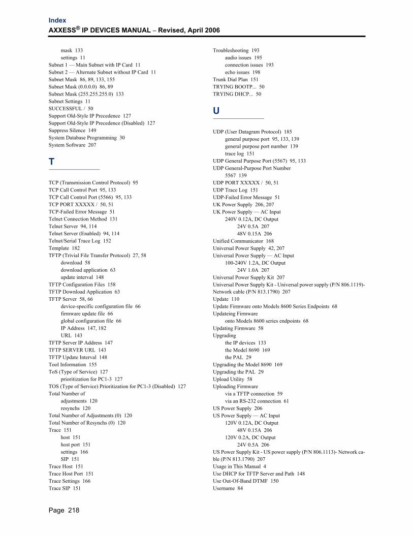
IndexAXXESS® IP DEVICES MANUAL – Revised, April 2006
mask 133settings 11
Subnet 1 — Main Subnet with IP Card 11Subnet 2 — Alternate Subnet without IP Card 11Subnet Mask 86, 89, 133, 155Subnet Mask (0.0.0.0) 86, 89Subnet Mask (255.255.255.0) 133Subnet Settings 11SUCCESSFUL / 50Support Old-Style IP Precedence 127Support Old-Style IP Precedence (Disabled) 127Suppress Silence 149System Database Programming 30System Software 207
T
TCP (Transmission Control Protocol) 95TCP Call Control Port 95, 133TCP Call Control Port (5566) 95, 133TCP PORT XXXXX / 50, 51TCP-Failed Error Message 51Telnet Connection Method 131Telnet Server 94, 114Telnet Server (Enabled) 94, 114Telnet/Serial Trace Log 152Template 182TFTP (Trivial File Transfer Protocol) 27, 58
download 58download application 63update interval 148
TFTP Configuration Files 158TFTP Download Application 63TFTP Server 58, 66
device-specific configuration file 66firmware update file 66global configuration file 66IP Address 147, 182URL 143
TFTP Server IP Address 147TFTP SERVER URL 143TFTP Update Interval 148Tool Information 155ToS (Type of Service) 127
prioritization for PC1-3 127TOS (Type of Service) Prioritization for PC1-3 (Disabled) 127Total Number of
adjustments 120resynchs 120
Total Number of Adjustments (0) 120Total Number of Resynchs (0) 120Trace 151
host 151host port 151settings 166SIP 151
Trace Host 151Trace Host Port 151Trace Settings 166Trace SIP 151
Troubleshooting 193audio issues 195connection issues 193echo issues 198
Trunk Dial Plan 151TRYING BOOTP... 50TRYING DHCP... 50
U
UDP (User Datagram Protocol) 185general purpose port 95, 133, 139general purpose port number 139trace log 151
UDP General Purpose Port (5567) 95, 133UDP General-Purpose Port Number
5567 139UDP PORT XXXXX / 50, 51UDP Trace Log 151UDP-Failed Error Message 51UK Power Supply 206, 207UK Power Supply — AC Input
240V 0.12A, DC Output24V 0.5A 20748V 0.15A 206
Unified Communicator 168Universal Power Supply 42, 207Universal Power Supply — AC Input
100-240V 1.2A, DC Output24V 1.0A 207
Universal Power Supply Kit 207Universal Power Supply Kit - Universal power supply (P/N 806.1119)-Network cable (P/N 813.1790) 207Update 110Update Firmware onto Models 8600 Series Endpoints 68Updateing Firmware
onto Models 8600 series endpoints 68Updating Firmware 58Upgrading
the IP devices 133the Model 8690 169the PAL 29
Upgrading the Model 8690 169Upgrading the PAL 29Upload Utility 58Uploading Firmware
via a TFTP connection 59via an RS-232 connection 61
US Power Supply 206US Power Supply — AC Input
120V 0.12A, DC Output48V 0.15A 206
120V 0.2A, DC Output24V 0.5A 206
US Power Supply Kit - US power supply (P/N 806.1113)- Network ca-ble (P/N 813.1790) 207Usage in This Manual 4Use DHCP for TFTP Server and Path 148Use Out-Of-Band DTMF 150Username 84
Page 218

IndexAXXESS® IP DEVICES MANUAL – Revised, April 2006
V
Version 132Virtual Local Area Network (VLAN) Tagging Support 22VLAN IDs 23VLAN Tagging-Related Issues 205Vocoder Type 96, 104, 113, 135Vocoder Type (Default) 96, 104, 113Vocoder Type (FF - Default) 135Vocoders (Voice Codec) 8Voice Activity Detection 96, 107, 115, 149Voice Activity Detection (Disabled) 96, 107, 115Voice Mail 153Voice Over IP
across frame relay bandwidth calculation 9bandwidth calculation 8
Volume 156
W
WAITING FOR 51WAITING FOR DOWNLOAD 49Waiting for Ethernet Address 51Wall Mounting 44
the Axxess IP PhonePlus 44the Eclipse IP PhonePlus 45the IP PhonePlus 44the Model 8600 series endpoints 46
Web Interface 145Web Interface Changes 146Web Server 94, 114Web Server (Enabled) 94, 114Windows CE .NET Programming (Model 8690 Only) 168WINS Server 93, 101, 113WINS Server (0.0.0.0) 93, 101, 113WINS Server IP Address 133, 136, 140WINS Server IP Address (0.0.0.0) 133, 136, 140
Page 219

IndexAXXESS® IP DEVICES MANUAL – Revised, April 2006
Page 220


Part No. 835.2195-18Revised April 2006
A946/32:6A