iot-magazine-2015.pdf
TRANSCRIPT

1
INT
ER
NE
T O
F T
HIN
GS
Finland / 1 • 2015
INTERNET OF THINGS ///// Finland 1
/ 201
5
3 Connecting All Things Around Us!
4 Internet Of Things Is Mainstreams
6 Attestable Trusted Boot for Everyone 10 Ecosystem Business Models for the Internet of Things
14 Lte Enhancements for Internet of Things
18 Iot Business Ecosystems: Evolutionary Perspective for Business Development
21 Study of the Duty Cycle Challenges for Short Range Devices Deployment Based on the IEEE 802.11ah in M2M and IoT Network
25 Academia-Assisted Technology Transfer from Industry to Open Source: Case Lokki
28 Moving Computation to the Edges of Iot
32 Wearable Sensor Vest With Wireless Charging – An Energy-Efficient Safety Solution for Children
36 Remote Attestation Utilizing Trusted Execution Environment
40 Ui Design Process of the Assisted Living Service System for Senior Citizens
47 The Elisa Iot™ Development and Service Platform Promotes Creation
49 Blending Problem- And Project-Based Learning in Internet of Things Education: Case Exact Greenhouse
53 My Smart Home with the Head in the Cloud
56 Standards in Iot, Industrial Internet and Condition-Based Maintenance
60 Smart Homes: Opportunities and Risks
INTERNET OF THINGS ///// Finland
1/2015
Editor: Samu Varjonen,
University of Helsinki
Publisher: DIGILE
Graphic Design: Unigrafia
www.iot.fi

3
INT
ER
NE
T O
F T
HIN
GS
Finland / 1 • 2015
I n Finland’s national IoT Program we are creating partnerships with Finnish companies, universities, and international organizations. The program also
helps the Finnish industry to pioneer the development of new products, services and standards for IoT and has a global competitive advantage due to its existing know-how and active cross-industrial cooperation in the Information and Communications Technology (ICT) sector. At the beginning of 2012, Finland’s national Internet of Things (IoT) consortium partners started their collaboration and as of today several hundreds of deliverables, publications, prototypes and commercial products were developed by close to 400 experts. Up to now, around 50 national and international organizations were part of our IoT Program.
In order to flourish on a global level, IoT needs to support a multitude of diverse “smart” objects, which are extended with sensors, actuators, RFIDs or processors. Those objects must be uniquely identifiable and can be monitored or manipulated via various networks; they can autonomously transmit data and communicate with other objects or machines. Some of the key challenges of our research and development activities are the elaboration of strong security and privacy foundations, development of common IoT platforms, international standardization efforts and efforts to reduce the energy consumption of devices that are attached to objects. One of our goals for 2015 is to further develop a real-time data-handling platform for constrained devices that can be utilized by any vertical business segment.
The research and development conducted in the IoT Program is funded by Tekes and steered by Digile. Tekes is the Finnish Funding Agency for Technology and Innovation. It is the most important expert organization for financing research, development and innovation in Finland. Research, development and innovation funding is targeted to projects that create in the long-term the greatest benefits for the economy and society. Tekes does not derive any financial profit from its activities, nor claim any intellectual proprietary rights. Digile is one of Finland’s Strategic Centres for Science Technology and Innovation (In Finnish: “SHOK” or “Strategisen huippuosaamisen keskittymät”) and brings together strategically important research programs or projects, thereby giving those involved a framework in which they not only benefit from the wide range of partners involved.
Tony Jokikyyny
3
INT
ER
NE
T O
F T
HIN
GS
Finland / 1 • 2015
Billions of connected devices will change our way of living.”
Tony JokikyynyEricsson R & DFocus Area Director of Finland’s National Internet of Things Program
CONNECTING ALL THINGS AROUND US!
A new ubiquitous computing and communications era has gradually started and now it is changing our working environment and everyday life. The number of devices connected to the Internet is increasing at a rapid pace and consequently, the Internet of Things (IoT) business sector is projected to generate promising revenue streams. These revenue streams result from new business models that are utilizing the benefits of smart technologies, which are connecting everyday objects via Internet or other networks.
Feel free to visit our website (www.iot.fi) where you can read more about our activities. This magazine will give an insight into some of the R&D activities performed by our consortium partners within the IoT Program. I hope you enjoy reading our magazine with articles about R&D activities performed by our consortium partners of Finland’s national IoT Program!
4
INTERNET OF THINGS IS MAINSTREAM
Internet of Things and its services are becoming part of our everyday life, ways of working, and business.
Sasu Tarkoma
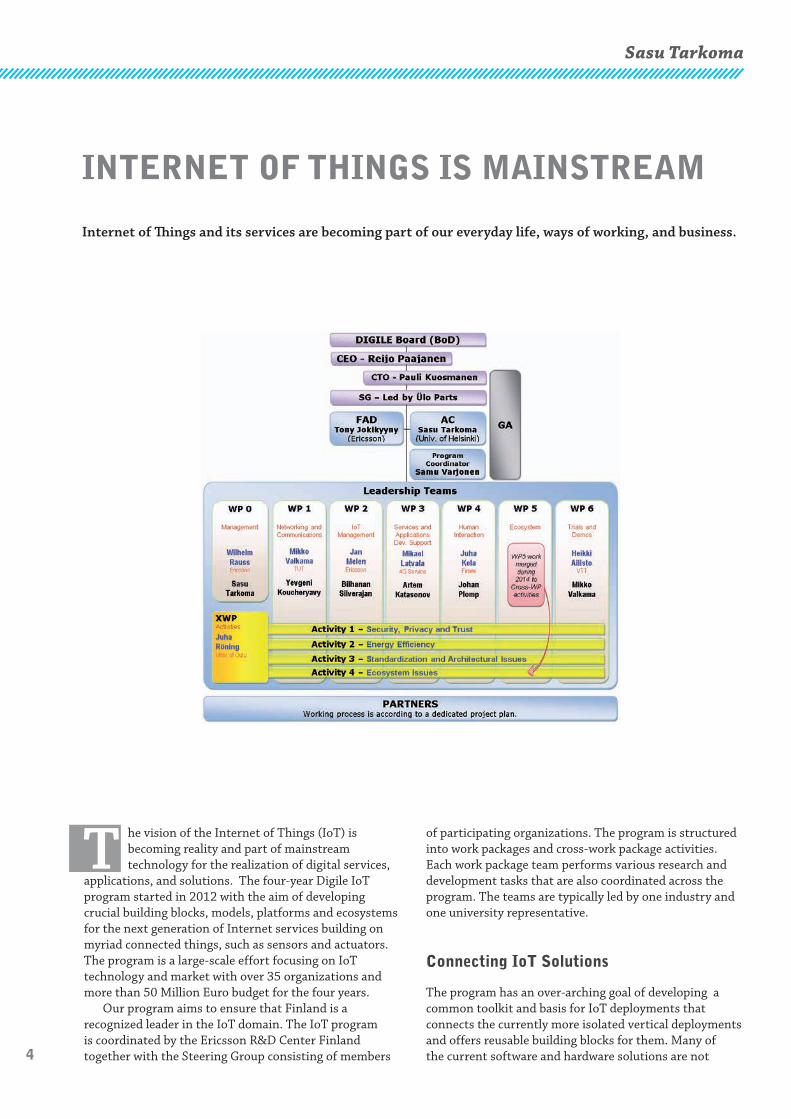
T he vision of the Internet of Things (IoT) is becoming reality and part of mainstream technology for the realization of digital services,
applications, and solutions. The four-year Digile IoT program started in 2012 with the aim of developing crucial building blocks, models, platforms and ecosystems for the next generation of Internet services building on myriad connected things, such as sensors and actuators. The program is a large-scale effort focusing on IoT technology and market with over 35 organizations and more than 50 Million Euro budget for the four years.
Our program aims to ensure that Finland is a recognized leader in the IoT domain. The IoT program is coordinated by the Ericsson R&D Center Finland together with the Steering Group consisting of members
of participating organizations. The program is structured into work packages and cross-work package activities. Each work package team performs various research and development tasks that are also coordinated across the program. The teams are typically led by one industry and one university representative.
Connecting IoT Solutions
The program has an over-arching goal of developing a common toolkit and basis for IoT deployments that connects the currently more isolated vertical deployments and offers reusable building blocks for them. Many of the current software and hardware solutions are not

5
INT
ER
NE
T O
F T
HIN
GS
Finland / 1 • 2015
Achievements
interoperable with each other. Our program aims to create new ecosystems through the common basis and toolkit and by promoting innovation in the application and service layer thus opening the IoT software development process.
One emerging proposal for addressing innovation in IoT software is to support the formation of IoT hubs and markets. The former is a managed service that abstracts IoT devices and exposes certain data- and device-sharing interfaces to the developers and other hubs. The latter is a clearinghouse for IoT connectivity and data that would ideally allow the discovery and integration of IoT devices and data with applications.
Consortium
The consortium partners of the IoT Program come from various industry sectors, which gives us an excellent product and research portfolio.
F-Secure, Elektrobit, Intel, Softera and Ericsson have a strong background in soft- and hardware development, ICT, security, the automotive and wireless industries and consumer electronics.
Participating SMEs such as Jolla, Mikkelin Puhelin, Finwe, 4G-Service and Nixu bring benefits to our joint research with their experience in IT services, ICT, security, energy management, home automation, digital services, vehicle communication etc.
On the international level, we are happy to cooperate with other organizations, such as the Wuhan University China, the French Agency for International Business Development, Intel USA and other organizations in Europe, USA and Asia.
Eight consortium partners come from Finnish academic research institutions; however, most contributions come from VTT Technical Research Centre of Finland, the University of Oulu, Tampere University of Technology, Aalto University and the University of Helsinki.
You can find an updated list of our partnerships on the Internet: www.iot.fi/partners
International Evaluation
Two distinguished international reviewers evaluated the program on 1-2 September 2014. The reviewers studied selected materials provided by the program before the review and during the review the key information of the program was presented as well as demonstrations. They interviewed company and research organization participants as well as the Digile board and the program steering group.
The main observations of the evaluation pertain to the vision, strategy, execution, and results of the program as well as recommendations for the program for the final year. Overall, the vision and mission of the program were seen to be bold and well articulated and the program
largely on track to achieve them. The strategy was seen to be functional to date. According to the reviewers, the execution of the program has proven to be successful to date. Some participating organizations are reported to achieve outstanding results in publications, close-to-market prototypes and contributions to standards. Further work on business development and strengthening of the verticals were recommended. We have planned the fourth year of the program with the evaluation feedback and recommendations in mind.
Prof. Sasu Tarkoma from the University of Helsinki takes care of the academic coordination of the Program to ensure high-quality IoT research, which is disseminated in world-class conferences, workshops and journals.
• The program has completed more than 130 scientific articles. We published 39 articles in 2013 and completed 48 articles in 2014. Key publications forums in 2014 include IEEE Communications, IEEE Network, IEEE Transactions on Mobile Computing, IEEE JSAC, ACM Ubicomp (best paper award), and Cambridge University Press.
• Significant contributions to IETF, IEEE 802.11ah, 3GPP LTE
• International research evaluation of the program was carried out in the Fall 2014. The execution of the program was seen to be successful to date.
• The Internet of Things Hub and Market concepts for bottom-up formation of IoT ecosystems. Digile has an active business ecosystem project pertaining to IoT hubs.
• Many prototypes, demonstrations and posters shown at national and international forums.
• New national and international IoT partnerships.
Sasu TarkomaUniversity of Helsinki
Academic Coordinator ofFinland’s national Internet of Things Program
6
ATTESTABLE TRUSTED BOOT FOR EVERYONE
the CPU [1, 2] – for secure storage of the attestation response signing key, collecting attestation data and constructing properly formed and signed attestation responses. Otherwise, once the device has been completely penetrated by some invading or intentionally installed malware it could generate some known-to-be-acceptable attestation response with the current challenge and sign it properly.
Current PCs often have a TPM chip for remote attestation and the ARM family processors widely used in embedded and mobile systems usually include the TrustZone feature [3] providing a functional TEE for a software implementation. For a large mobile or embedded Device manufacturer it is relatively easy to have its code properly signed – either by ordering a large batch of SoCs with the customer’s root of trust programmed into the OTP memory during chip manufacture or having its software (or, at least signing keys) certified by the SoC manufacturer’s keys. As both of these approaches require
Aarne Rantala and Markku Kylänpää
Introduction
E nforcing trusted boot [1] by executing only code signed by an authorised entity mandates protected initial startup code and the root of trust
(topmost public key for checking signatures). In order to defeat moderate hardware hacking these components are usually integrated to the same SoC as the CPU core itself. The initial startup code is stable and general enough to be stored in ROM. The same does not apply to the root of trust as there is a risk that the topmost signing keypair becomes compromised and separate customers may want to use their own root of trust. Because of this the root of trust is often stored in OTP memory, whose contents can be set once – usually towards the end of the SoC manufacturing process but sometimes after the component has left the manufacturer’s premises.
Trustworthy remote attestation requires a protected environment – either a dedicated component like a Trusted Platform Module (TPM) chip [1] or a hardware protected Trusted Execution Environment (TEE) within
An essential requirement for a trustworthy network is that its nodes – even simple and inexpensive ones – are started with and running trustworthy code, and that it is possible to attest to that. Proper attestable trusted boot requires close co-operation between System-on-a-Chip (SoC) manufacturer and Device manufacturer, as an unbroken trust chain between the Device manufacturer’s software and a hardware trust anchor residing in the SoC component are required. The hardware trust anchor is usually a block of One-Time Programmable (OTP) memory containing a Root Public Signing key or, usually, its hash. This Root Signing key belongs either to the Device manufacturer or to the SoC manufacturer – in the latter case either the Device manufacturer’s Root Public Signing key or Device manufacturer’s software must be certified with the SoC manufacturer’s Signing key. In every case the Device manufacturer needs to be recognized by the SoC manufacturer which is impractical for small Device manufacturers.
One possibility is to ship SoC components with unprogrammed OTP memory and facilitate OTP memory programming by Device manufacturers. In principle, with this mechanism (provided that modifying the OTP memory after initial programming can be disabled) any small Device manufacturer can produce devices with as secure boot as large manufacturers who are able to order batches of SoCs with their own trust anchor preprogrammed. However, there is one problem remaining – the user of the device is not able to attest whether the device really is genuine and uncompromised.
The remaining problem can be solved by remote attestation of the device using sufficiently protected local attestation software and an attestation server belonging to the Device manufacturer. The ARM TrustZone Trusted Execution Environment (TEE) provides sufficient protection for the local attestation software, but as all software executed in TEE must be properly signed that software must come from the SoC manufacturer or someone recognized by him. This study presents generic TEE software for startup and attestation that can be supplied and signed by the SoC manufacturer and which can be utilized by any Device manufacturer without any connection to the SoC manufacturer. It suffices that the Device manufacturer signs and sets up the non-TEE software in such a way that the generic TEE software is able to make trustworthy measurements of the device. These measurements are sent to the Device manufacturer’s attestation server, which is able to verify whether the measurements were made by a genuine TEE attestation software and if they represent a genuine uncompromised device set up by said Device manufacturer. This process is effective without programmable OTP memory and an unbroken trust chain between the hardware trust anchor and Device manufacturer’s software.
7
INT
ER
NE
T O
F T
HIN
GS
Finland / 1 • 2015
close co-operation between SoC and Device manufacturers they are not open to smaller mobile or embedded Device manufacturers who produce short batches of (often inexpensive) devices. One possibility is to use SoCs shipped with programmable OTP memory [4] in which case the Device manufacturer programs its own root of trust to the OTP memory and signs all code using its own keys.
The remaining problem is that the user of the device is not able to attest, on his own, whether the device really is genuine and uncompromised. Incidentally, this applies to a certain degree to a large Device manufacturer, too. The difference is that the appearance and behaviour of a well-known product is usually widely known, so any malware trying to replace it needs to mimic it closely. When the target is some less-known product mimicking needs not be so accurate. In both cases the most straightforward way to get a reasonable assurance is to use remote attestation, i.e. an attestation server belonging to the Device manufacturer or some trusted third party sends an attestation request to the device and verifies the response. Of course, the attestation server must be able to authenticate the attestation client in the device, i.e. it must come from a credible and recognisable vendor.
Generic SoC manufacturer support
One possible solution is that the SoC manufacturer provides a properly signed generic code package which initialises the SoC, sets up TEE and starts a properly set up Device manufacturer’s software outside the TEE (the so-called Public side) and facilitates its subsequent remote attestation. For Device manufacturers it is sufficient to set up their code according to the rules enforced by this code package – no explicit transactions between SoC manufacturer and Device manufacturers are needed.
This code consists of early phase boot code that initialises the SoC and sets up TEE of the device, and TEE services implementing Secure Storage, Secure Display and security sensitive parts of the remote attestation client. They protect confidentiality of data belonging to TEE against possibly hostile Public side software, even when it is displayed (or replayed in some other way) to the user. It verifies that Public side software is set up properly and loads it only in that case – otherwise it expects that setting up the Public side is incomplete and is ready to perform its part in that process. After the properly set up Public side code is loaded and started it keeps its identity information secure and is ready to respond to remote attestation requests from the Device manufacturer’s (or some trusted third party’s) security server.
Recognisable Device manufacturer software configuration
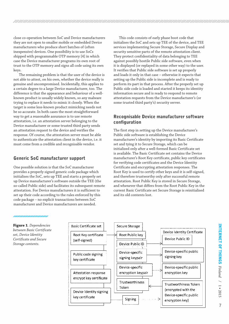
The first step in setting up the Device manufacturer’s Public side software is establishing the Device manufacturer’s identity by importing its Basic Certificate set and tying it to Secure Storage, which can be initialized only after a well-formed Basic Certificate set is available. The Basic Certificate set contains the Device manufacturer’s Root Key certificate, public key certificates for verifying code certificates and the Device Identity Certificate and encrypting attestation responses. The Root Key is used to certify other keys and it is self-signed, and therefore trustworthy only after successful remote attestation. Root Public Key is stored in Secure Storage, and whenever that differs from the Root Public Key in the current Basic Certificate set Secure Storage is reinitialised and its old contents lost.
Figure 1. Dependencies between Basic Certificate set, Device Identity Certificate and Secure Storage contents.

8
The next phase is setting up the device’s own identity by generating its Public ID and device-specific signing and encryption keypairs, storing them to Secure Storage and sending Public ID and device-specific public keys to the Device manufacturer’s security server. The Device manufacturer’s Security server shall combine these and an encrypted Trustworthiness Token to the Device Identity Certificate, sign it with the Identity Signing Key and send it back to the device. The Trustworthiness Token is a recognisable picture, tune, etc. which can be played back when the TEE software finds that the Public side is still healthy. It must be encrypted with the device-specific encryption key and its playback should be through Secure Display so that undetected Public side malware cannot capture it.
Device startup
After reset the startup code first verifies and starts other parts of the SoC manufacturer’s code package. After TEE is set up properly the startup code checks the Public side software by the Device manufacturer:
1. The Basic Certificate set should be found – if not, the startup code starts waiting for one.
2. If the Basic Certificate set is found, Secure Storage is checked if it is initialised and already contains the Root Public key – if not, it is initialised and new device-specific public keys are exported for Device Identity Certificate generation.
3. If Secure Storage is valid, Device Identity Certificate is looked up next. If not found or invalid, the startup code starts waiting for one.
4. At last, the Public side software (from the Device manufacturer) is looked up – if it is found and it is properly signed, the Trustworthiness Token is displayed (or played back in some other way) and the Public side software is started.
After the Public side startup the normal function of the device is carried out by the Public side code, while the TEE software is ready to perform its part in responding to attestation requests. Additionally, the TEE software may provide TPM-like functionality to additional Public side software measurements.
Remote attestation
For remote attestation to be trustworthy it must be started from some other device than the one being attested – if the device were already penetrated it would connect to some fake attestation server instead of the genuine one. Some mechanism to connect the attestation session in the attestation server and the device being attested is also needed. Otherwise an attacker could redirect attestation messages to some known-to-be-good device which, although being genuine, is in no way connected to functions whose appropriate execution is checked. Therefore, the attestation server should select some session indicator like a PIN code, tune, etc. to be displayed by the device being attested in order to designate the physical device being attested.
1. The attestation procedure is started in the attestation server and the session indicator is generated and displayed to the user.
2. The attestation server sends the attestation request with the session indicator (and an ordinary attestation nonce) to the client being attested.
3. Upon receiving the attestation request the device invokes the attestation client TEE component that checks if the device is running appropriately configured Public side software, and not e.g. waiting for one. If the device is in order, both the session indicator and current Trustworthiness Token are displayed (using Secure Display) to indicate the device being attested.
4. The attestation response is prepared and sent, containing the nonce, Basic Certificate set, Device Identity Certificate, Trustworthiness Token and session indicator. It is signed with the device-specific signing key and encrypted with the attestation response encryption public key.
5. The attestation server checks the response: it must belong to the current session, signatures must be correct and Basic Certificate set public keys must belong to this Device manufacturer. Its authenticity is proved by it being signed with a key certified by the Device Identity Certificate.
6. (Optional) A new Device Identity Certificate with a personalised Trustworthiness Token may be generated and installed to the successfully attested device. Thereafter such a Trustworthiness Token will indicate that this particular device has been successfully attested.
ATTESTABLE TRUSTED BOOT FOR EVERYONE
Device manufacturer needs to be recognized buy the SoC manufacturer which is impractical for small Device manufacturers.

9
INT
ER
NE
T O
F T
HIN
GS
Finland / 1 • 2015ATTESTABLE TRUSTED BOOT FOR EVERYONE
Conclusions and future work
The presented generic bootstrap and attestation framework facilitates reasonably trustworthy bootstrapping also to small device manufacturers who are unable to procure large batches of components with a customised root of trust and who will also find it difficult and slow to get their code or signing certificates certified by SoC manufacturers. By utilising the described remote attestation service - possibly even with a personalised Trustworthiness Token - this scheme provides at least as credible security than just a logo of a ‘big name’ manufacturer on the device. The attestation component will also be useful in such cases when small device manufacturers are able to set up their own root of trust and certificate hierarchy by using SoCs with a modifiable OTP root of trust, but their customers find it difficult to ascertain that their devices really are genuine.
The presented framework is currently a plan only but the existing open source components like UEFI Tianocore EDK2 bootloader [5], ARM Trusted Firmware [6] and Linaro OP-TEE [7] constitute a possible starting point from which this plan could be realised with a significant but realistic amount of work. Another question is if the SoC manufacturers were to adopt and certify (literally) the outcome.
The remaining problem is that the user of the device is not able to attest, on his own, whether the device really is genuine and uncompromised.
References
[1] N.Asokan & al., ”Mobile Trusted Computing,” Proceedings of the IEEE, nro 8, August, pp. 1189-1206, 2014.
[2] Global Platform, ”GlobalPlatform made simple guide: Trusted Execution Environment (TEE) Guide,” [Online]. Available: http://www.globalplatform.org/mediaguidetee.asp.
[3] ARM Ltd, ”TrustZone,” [Online]. Available: www.arm.com/products/processors/technologies/trustzone/index.php.
[4] Freescale Semiconductor, ”MCIMX53 Multimedia Applications Processor Security Reference Manual,” [Online]. Available: http://www.freescale.com.
[5] Intel Corp., ”Tianocore - UEFI Development Kit 2014,” [Online]. Available: http://tianocore.sourceforge.net/wiki/Welcome.
[6] ARM Ltd, ”ARM-software/arm-trusted-firmware,” [Online]. Available: https://github.com/ARM-software/arm-trusted-firmware.
[7] Linaro, ”OP-TEE,” [Online]. Available: https://wiki.linaro.org/WorkingGroups/Security/OP-TEE.
Aarne Rantala and Markku KylänpääVTT Technical Research Centre of Finland
Espoo, Finland
10
Seppo Leminen, Mervi Rajahonka, Mika Westerlund and Riikka Siuruainen
Introduction
R ecent academic research suggests the need for expanding the focus in business models from a single company point of view to an ecosystem
perspective. In the Digile IoT programme, we investigated business models [1], ecosystem business models or “value designs” – as we [2] call them – in the emerging Internet of
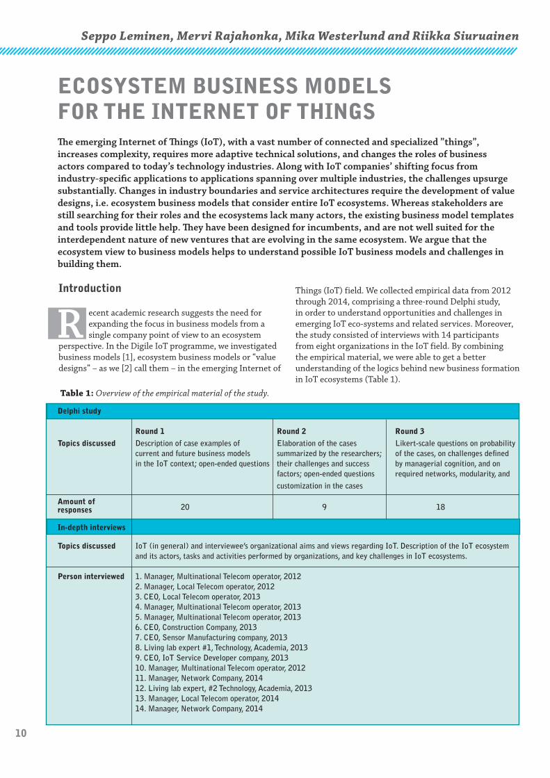
Things (IoT) field. We collected empirical data from 2012 through 2014, comprising a three-round Delphi study, in order to understand opportunities and challenges in emerging IoT eco-systems and related services. Moreover, the study consisted of interviews with 14 participants from eight organizations in the IoT field. By combining the empirical material, we were able to get a better understanding of the logics behind new business formation in IoT ecosystems (Table 1).
ECOSYSTEM BUSINESS MODELS FOR THE INTERNET OF THINGSThe emerging Internet of Things (IoT), with a vast number of connected and specialized ”things”, increases complexity, requires more adaptive technical solutions, and changes the roles of business actors compared to today’s technology industries. Along with IoT companies’ shifting focus from industry-specific applications to applications spanning over multiple industries, the challenges upsurge substantially. Changes in industry boundaries and service architectures require the development of value designs, i.e. ecosystem business models that consider entire IoT ecosystems. Whereas stakeholders are still searching for their roles and the ecosystems lack many actors, the existing business model templates and tools provide little help. They have been designed for incumbents, and are not well suited for the interdependent nature of new ventures that are evolving in the same ecosystem. We argue that the ecosystem view to business models helps to understand possible IoT business models and challenges in building them.
Table 1: Overview of the empirical material of the study.
Delphi study
Round 1 Round 2 Round 3
Topics discussed Description of case examples of Elaboration of the cases Likert-scale questions on probability current and future business models summarized by the researchers; of the cases, on challenges defined in the IoT context; open-ended questions their challenges and success by managerial cognition, and on factors; open-ended questions required networks, modularity, and
customization in the cases
Amount ofresponses 20 9 18
In-depth interviews
Topics discussed IoT (in general) and interviewee’s organizational aims and views regarding IoT. Description of the IoT ecosystem and its actors, tasks and activities performed by organizations, and key challenges in IoT ecosystems.
Person interviewed 1. Manager, Multinational Telecom operator, 2012 2. Manager, Local Telecom operator, 2012 3. CEO, Local Telecom operator, 2013 4. Manager, Multinational Telecom operator, 2013 5. Manager, Multinational Telecom operator, 2013 6. CEO, Construction Company, 2013 7. CEO, Sensor Manufacturing company, 2013 8. Living lab expert #1, Technology, Academia, 2013 9. CEO, IoT Service Developer company, 2013 10. Manager, Multinational Telecom operator, 2012 11. Manager, Network Company, 2014 12. Living lab expert, #2 Technology, Academia, 2013 13. Manager, Local Telecom operator, 2014 14. Manager, Network Company, 2014

11
INT
ER
NE
T O
F T
HIN
GS
Finland / 1 • 2015
Challenges in building business models in the emerging iot ecosystems
The creation of new IoT-enabled services, such as services for elderly people staying in their homes longer, requires extensive cross-industry collaboration that will affect current industry boundaries and operating models of involved companies. The findings from our Delphi study and interviews suggest that the challenges are significant, as companies aim at transforming from industry-specific vertical IoT applications to horizontal applications spanning over multiple industries.
“When services are seen from the consumer’s point of view, the same service may include many services from different industries, such as banks, government, and shopping services. In the future, there will be more multi-sectoral services. If we think too narrowly, we would leave out perhaps the most potential services.” (Manager, Network Company, 2014)
A breakthrough observation in our research was to realize that the interviewees were talking about challenges in building ecosystem business models at different levels. Thus, we have to pay attention to whether the challenges are at the level of a specific firm, its value-creating network, or the surrounding ecosystem. In building business models for emerging ecosystems, the most critical challenges typically are not at the firm level, but at the ecosystem or network level and industry interfaces.
When asked about ecosystem level challenges, the experts mentioned that for the time being there are only isolated actor- or industry-specific incremental innovations in the Finnish IoT field, with no clear killer applications or dominant designs or standards. Instead, there are lots of small applications that fail to work together. Some of the experts suspected that IoT services are fragmented by their nature, because the customer needs are becoming more and more heterogeneous. Moreover, the standardization of service interfaces, which is needed in the IoT field in addition to technological standards, is far more difficult than standardization related to physical things.
Although there are publicly funded IoT projects in Finland, proper ecosystems have not yet been formed. Some respondents hoped for new legislation that would force the development of commercial IoT innovations and serve as a value driver for IoT ecosystems (e.g., road tolls, stricter rules on food security, energy consumption, or eco-efficiency). Regarding the more general ecosystem level challenges, the experts mentioned that in some industries there are factors that may slow the development down: the dominance of incumbents such as ICT or device suppliers; the fragmented structure of the market; and regulation that creates barriers for entering the market.
“It is unclear who would be interested in driving standardisation in for example health care sector.” (CEO, Sensor Manufacturing Company, 2013)
“Regulation in the public sector makes it fragmented, and it is very difficult to develop services or to get customers there.” (CEO, Local Telecom operator, 2014)
According to the experts, the actor who gathers the data would be the most viable choice for managing the IoT network. However, the data must be opened so that several actors have possibility to receive and refine the data that are gathered with the help of IoT technologies. The actors have to be able to step out of their current roles and develop services with new partners, including customers and end-users. The entire value-creating network should be involved in developing customer-oriented services. In order to succeed, the IoT business models need to take account and motivate all actors to network and offer whole solutions with others. It is also crucial that end-customers understand the benefits and are willing to pay for the products and services to make mass-markets to come true.
“The actors are stuck into their present roles. They fail to see the end-user behind their own customers. The entire value chain should get involved into developing services.” (CEO, Local Telecom Operator, 2014)
Commercialization and networking are considered major challenges for IoT companies in Finland. The established organizational structures or operating models are hard to adapt to IoT-enabled models. Rather, companies deem that it is nobody’s business to develop IoT solutions, there are no incentives to sell these solutions, IoT solutions are difficult to sell because they are not off-the-shelf products, and neither the seller nor the buyer knows what the benefits of using the IoT are. Although the interviewees perceived the biggest potential of the IoT is in novel value-added cross-industry services, the most common drivers of IoT at the company level emphasized efficiency (e.g., energy efficiency, cost efficiency, and efficient production of services).
“IoT will have a breakthrough only when and if people get clear and concrete benefits.” (Manager, Multinational Telecom operator, 2013)
How to proceed from promises to reality
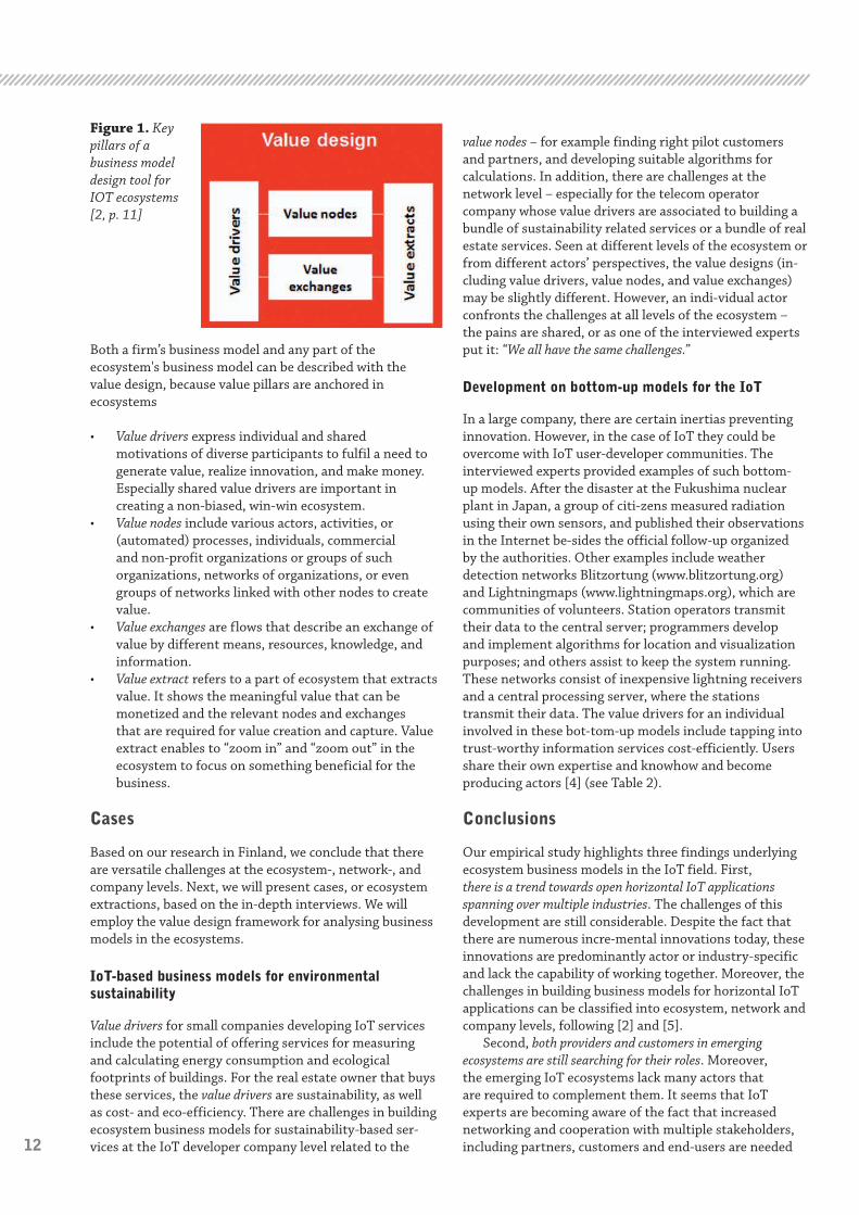
Most of the business promises of the IoT have not yet been realized. Acknowledging [2], we suggest that managers need to shift their focus from the business model of a firm to ecosystem business models, also known as “value designs”. The existing business model templates and tools are not well suited for the interdependent nature of companies that are evolving in the same ecosystem, because they have been designed for dealing with the challenges faced by single incumbents [4]. The eco-system view to business models helps to understand possible IoT business models and challenges in building them. The concept of value design illustrates how value is deliberately created and captured in an ecosystem. The value design can be conceptualized by four pillars: ‘value drivers’, ‘value nodes’, ‘value exchanges’, and ‘value extracts’ [2] (see Figure 1).
12
ECOSYSTEM BUSINESS MODELS FOR THE INTERNET OF THINGS
Both a firm’s business model and any part of the ecosystem's business model can be described with the value design, because value pillars are anchored in ecosystems
• Value drivers express individual and shared motivations of diverse participants to fulfil a need to generate value, realize innovation, and make money. Especially shared value drivers are important in creating a non-biased, win-win ecosystem.
• Value nodes include various actors, activities, or (automated) processes, individuals, commercial and non-profit organizations or groups of such organizations, networks of organizations, or even groups of networks linked with other nodes to create value.
• Value exchanges are flows that describe an exchange of value by different means, resources, knowledge, and information.
• Value extract refers to a part of ecosystem that extracts value. It shows the meaningful value that can be monetized and the relevant nodes and exchanges that are required for value creation and capture. Value extract enables to “zoom in” and “zoom out” in the ecosystem to focus on something beneficial for the business.
Cases
Based on our research in Finland, we conclude that there are versatile challenges at the ecosystem-, network-, and company levels. Next, we will present cases, or ecosystem extractions, based on the in-depth interviews. We will employ the value design framework for analysing business models in the ecosystems.
IoT-based business models for environmental sustainability
Value drivers for small companies developing IoT services include the potential of offering services for measuring and calculating energy consumption and ecological footprints of buildings. For the real estate owner that buys these services, the value drivers are sustainability, as well as cost- and eco-efficiency. There are challenges in building ecosystem business models for sustainability-based ser-vices at the IoT developer company level related to the
value nodes – for example finding right pilot customers and partners, and developing suitable algorithms for calculations. In addition, there are challenges at the network level – especially for the telecom operator company whose value drivers are associated to building a bundle of sustainability related services or a bundle of real estate services. Seen at different levels of the ecosystem or from different actors’ perspectives, the value designs (in-cluding value drivers, value nodes, and value exchanges) may be slightly different. However, an indi-vidual actor confronts the challenges at all levels of the ecosystem – the pains are shared, or as one of the interviewed experts put it: “We all have the same challenges.”
Development on bottom-up models for the IoT
In a large company, there are certain inertias preventing innovation. However, in the case of IoT they could be overcome with IoT user-developer communities. The interviewed experts provided examples of such bottom-up models. After the disaster at the Fukushima nuclear plant in Japan, a group of citi-zens measured radiation using their own sensors, and published their observations in the Internet be-sides the official follow-up organized by the authorities. Other examples include weather detection networks Blitzortung (www.blitzortung.org) and Lightningmaps (www.lightningmaps.org), which are communities of volunteers. Station operators transmit their data to the central server; programmers develop and implement algorithms for location and visualization purposes; and others assist to keep the system running. These networks consist of inexpensive lightning receivers and a central processing server, where the stations transmit their data. The value drivers for an individual involved in these bot-tom-up models include tapping into trust-worthy information services cost-efficiently. Users share their own expertise and knowhow and become producing actors [4] (see Table 2).
Conclusions
Our empirical study highlights three findings underlying ecosystem business models in the IoT field. First, there is a trend towards open horizontal IoT applications spanning over multiple industries. The challenges of this development are still considerable. Despite the fact that there are numerous incre-mental innovations today, these innovations are predominantly actor or industry-specific and lack the capability of working together. Moreover, the challenges in building business models for horizontal IoT applications can be classified into ecosystem, network and company levels, following [2] and [5].
Second, both providers and customers in emerging ecosystems are still searching for their roles. Moreover, the emerging IoT ecosystems lack many actors that are required to complement them. It seems that IoT experts are becoming aware of the fact that increased networking and cooperation with multiple stakeholders, including partners, customers and end-users are needed
Figure 1. Key pillars of a business model design tool for IOT ecosystems [2, p. 11]

13
INT
ER
NE
T O
F T
HIN
GS
Finland / 1 • 2015ECOSYSTEM BUSINESS MODELS FOR THE INTERNET OF THINGS
to overcome the barriers for change. The business actors are still stuck into their present roles, and fail to see the end-user be-hind their own customers. The entire value-creating network should be involved in developing ser-vices. In addition, deeper service and customer-oriented thinking are required.
Third, ecosystem perspective helps to understand possible IoT business models and challenges in building them. The major challenges in IoT field lie at the business network and ecosystem levels ra-ther than the company level. Our case examples of ecosystem extractions support the argument that the “value design” view presented by [2] is useful in analysing IoT ecosystem business models. IoT will have a breakthrough only when and if people/customers get clear and concrete benefits.
AUTHORS
Seppo Leminen(*), D.Sc. (Econ), Lic. Tech., Principal Lecturer and Adjunct ProfessorLaurea University of Applied Services, Vanha maantie 9, 02650 Espoo, [email protected], and Aalto University School of Business, Department of Marketing, P.O. Box 21230, 00076 Aalto, Finland, [email protected] Mervi Rajahonka, D.Sc. (Econ), M.Sc. (Tech), LL.M.Laurea University of Applied Sciences, Vanha maantie 9, 02650 Espoo, Finland, and Aalto University School of Business, Department of Information and Service Economy, Logistics, P.O. Box 21220, 00076 AALTO, Finland, [email protected] Mika Westerlund, D.Sc. (Econ), Associate Professor, Sprott School of Business, Carleton University, 801 Dunton Tower, 1125 Colonel By Drive, Ottawa ON K1S 5B6 Canada, [email protected] Siuruainen, Senior Lecturer, M.Sc (Econ), Laurea University of Applied Sciences, Laurea SID Leppävaara, Vanha maantie 9, 02650 Espoo, Finland, [email protected]
Seppo LeminenLaurea University of Applied Sciences, Espoo, Finland Aalto University School of Business, Helsinki, Finland
Mervi Rajahonka Laurea University of Applied Sciences, Espoo, FinlandAalto University School of Business, Helsinki, Finland
Mika Westerlund Carleton University, Sprott School of Business, Ottawa, Canada
Riikka SiuruainenLaurea University of Applied Sciences, Espoo, Finland,
References
[1] Leminen, S.; Westerlund, M.; Rajahonka, M.; Siuruainen, R. (2012). Towards IOT ecosystems and business models. Internet of Things, Smart Spaces, and Next generation Networking, Lec-ture Notes in Computer Science, Volume 7469, pp. 15-26. S. Andreev et al. (Eds.): NEW2AN/ruSMART 2012, LNCS 7469, pp. 15-26. Springer-Verlag, Heidelberg (2012).
[2] Westerlund, M.; Leminen, S.; Rajahonka, M. (2014): Designing Business Models for the Internet of Things, Technology Innovation Management Review, July, pp. 5-14.
[3] Weiller, C.; Neely, A. (2013): Business Model Design in an Ecosystem Context. University of Cambridge Working Papers. Cambridge, UK: Cambridge Service Alliance
[4] Fleisch, E. (2010): What is the Internet of Things? An Economic Perspective. Economics, Man-agement, and Financial Markets. 5(2), pp. 125–157.
[5] Leminen, S.; Rajahonka, M.; Westerlund, M.; Siuruainen, R. (2014), Ecosystem business models for the Internet of things, XXIV European Association for Research on Services Conference (RESER), Helsinki, Finland, September 11-13, 2014 European Association for Research on Services (RESER) .
Table 2: Examples of extractions on value designs in the IoT ecosystems
Type of business model Value drivers Value nodes Value flows /exchanges Value extracts Challenges
IoT service developer Measuring and Company and their Information, service Company Developing algorithms,
benchmarking customers (real and money exchange developing finding partners, eco-efficiency estate owners), the service getting pilot (footprint) databases, customers; Who
algorithms owns the data? Bottom up models Tapping into Individuals Peer-to-peer information, Individuals co- Getting fair trustworthy producing and central database, payments producing and compensation of information consuming, possibly for devices, programming, using the service work and services cost- a roof organisation visualisation work investments efficiently
14
Background
R esearch and discussions on different technologies related to Internet of Things have gained much popularity lately, and various industry partners
are providing their visions and ideas on future networked societies. Wireless communications play a key role in these visions, and there are several technologies, which can be foreseen to be used to enable the connectivity required in these visions. A rough division can be made between short-range radio technologies, including many 802.11variants, different versions of Bluetooth, 802.15.4 or Zigbee variants and so on, and long-range technologies including cellular (GSM, WCDMA, LTE [1]), long-range 802.11 variants, SigFox [2] and LoRa [3].
Different categories of technologies can play different roles. Short-range radios can be used within enclosed or otherwise range-limited areas, such as apartment buildings or factories, to enable connectivity to a gateway, which would then be connected to the Internet using for example 3GPP technologies. This concept we call a Capillary Network [4]. Long-range technologies, on the other hand, have much more area coverage and directly connect the devices to a larger network through base stations or similar more centralized points of interest. Note that long range does not rule out possible device-to-device (D2D) or mesh connections between the devices themselves. Depending on the technology D2D can be enabled using said long-range technology, or if the devices are equipped with multi-mode radios using some of the short-range technologies. We will not elaborate more on the D2D options in this article, however.
Some of the proprietary long-range radio technologies appearing recently, such as Weightless by Neul, SigFox and LoRa are designed with low-end IoT applications in mind.
Seppo Leminen1,2,* , Mervi Rajahonka4 , Riikka Siuruainen1, and Mika Westerlund 31111,
1 Laurea University of Applied Sciences, Espoo, Finland email: [email protected] Aalto University School of Business, Department of Marketing, Helsinki, Finland3 Carleton University, Sprott School of Business, Canada4 Aalto University School of Business, Department of Information and Service Economy*Corresponding author
Tuomas Tirronen
This means they are designed for low data volumes with very low data rates. They claim to provide long-range coverage and low energy consumption resulting in long potential battery lifetimes. However, these technologies are proprietary and use ISM or unlicensed spectrum. This makes it difficult to scale these systems with the projected IoT penetration, and interference issues may make the radio link unreliable especially with traffic growth on both long- and short-range technologies using the same unlicensed bands. Also, the new technologies will require building and installing new infrastructure.
To address the need for long-range, low-power and cellular radio technology for IoT, there are several tracks in 3GPP which are aiming to fill the requirements of typical IoT applications. In LTE several enhancements and optimizations for MTC applications have been included in the standard the last couple of years. In GERAN work is ongoing both on a GSM evolution for IoT and new, narrowband, cellular technologies aimed at building IoT-only networks are studied. In the following we will focus on LTE evolution for MTC and especially from a radio access network point of view.
LTE MTC in 3GPP Release 12
Release 12 work has been completed, and there are several improvements for MTC included. As the requirements for an IoT radio are different from those for mobile broadband, work was started to define lower complexity devices. Although 3GPP does not dictate the cost of the devices directly, it can be said that lower complexity leads to lower costs as well, lowering the LTE chipset prices
LTE ENHANCEMENTS FOR INTERNET OF THINGS
Abstract
LTE has originally been designed for enhanced mobile broadband user experience with very fast downlink and uplink data rates and short latencies. For Internet of Things (IoT) and many typical Machine Type Communications (MTC) applications the requirements are different: long battery lifetime, low device cost and good coverage are considered very important to enable the visions of a networked society with billions of connected devices. For this reason, there has been ongoing work in different 3GPP working groups to make the LTE system and radio interface more compatible with the various IoT use cases. The recent developments include new lower complexity User Equipment (UE) categories, the possibility to use coverage enhancements for up to 15 dB better radio coverage and enhancements in battery lifetime through various power-saving mechanisms. In this article we will present the most recent advances for LTE with focus on the radio interface in the already completed 3GPP Release 12, and the ongoing work and upcoming features in 3GPP Release 13, to be completed in 2016.
15
INT
ER
NE
T O
F T
HIN
GS
Finland / 1 • 2015
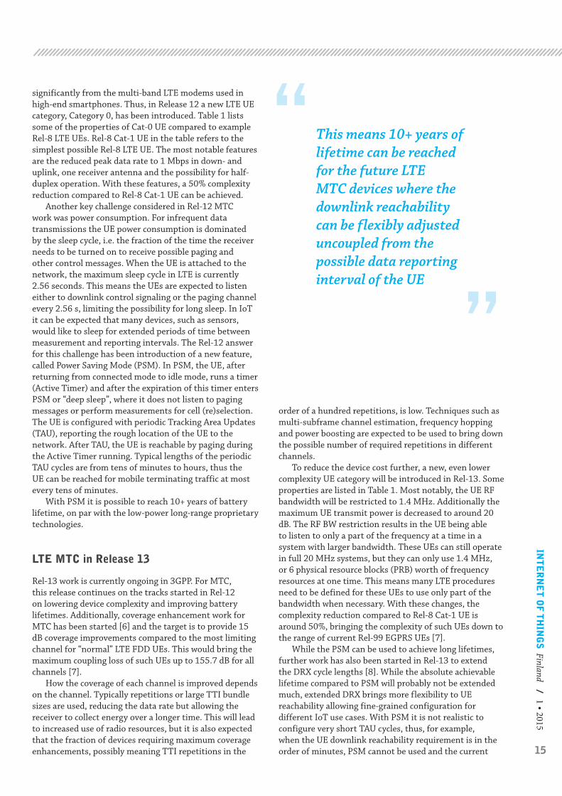
This means 10+ years of lifetime can be reached for the future LTE MTC devices where the downlink reachabilitycan be flexibly adjusted uncoupled from the possible data reporting interval of the UE
significantly from the multi-band LTE modems used in high-end smartphones. Thus, in Release 12 a new LTE UE category, Category 0, has been introduced. Table 1 lists some of the properties of Cat-0 UE compared to example Rel-8 LTE UEs. Rel-8 Cat-1 UE in the table refers to the simplest possible Rel-8 LTE UE. The most notable features are the reduced peak data rate to 1 Mbps in down- and uplink, one receiver antenna and the possibility for half-duplex operation. With these features, a 50% complexity reduction compared to Rel-8 Cat-1 UE can be achieved.
Another key challenge considered in Rel-12 MTC work was power consumption. For infrequent data transmissions the UE power consumption is dominated by the sleep cycle, i.e. the fraction of the time the receiver needs to be turned on to receive possible paging and other control messages. When the UE is attached to the network, the maximum sleep cycle in LTE is currently 2.56 seconds. This means the UEs are expected to listen either to downlink control signaling or the paging channel every 2.56 s, limiting the possibility for long sleep. In IoT it can be expected that many devices, such as sensors, would like to sleep for extended periods of time between measurement and reporting intervals. The Rel-12 answer for this challenge has been introduction of a new feature, called Power Saving Mode (PSM). In PSM, the UE, after returning from connected mode to idle mode, runs a timer (Active Timer) and after the expiration of this timer enters PSM or “deep sleep”, where it does not listen to paging messages or perform measurements for cell (re)selection. The UE is configured with periodic Tracking Area Updates (TAU), reporting the rough location of the UE to the network. After TAU, the UE is reachable by paging during the Active Timer running. Typical lengths of the periodic TAU cycles are from tens of minutes to hours, thus the UE can be reached for mobile terminating traffic at most every tens of minutes.
With PSM it is possible to reach 10+ years of battery lifetime, on par with the low-power long-range proprietary technologies.
LTE MTC in Release 13
Rel-13 work is currently ongoing in 3GPP. For MTC, this release continues on the tracks started in Rel-12 on lowering device complexity and improving battery lifetimes. Additionally, coverage enhancement work for MTC has been started [6] and the target is to provide 15 dB coverage improvements compared to the most limiting channel for “normal” LTE FDD UEs. This would bring the maximum coupling loss of such UEs up to 155.7 dB for all channels [7].
How the coverage of each channel is improved depends on the channel. Typically repetitions or large TTI bundle sizes are used, reducing the data rate but allowing the receiver to collect energy over a longer time. This will lead to increased use of radio resources, but it is also expected that the fraction of devices requiring maximum coverage enhancements, possibly meaning TTI repetitions in the
order of a hundred repetitions, is low. Techniques such as multi-subframe channel estimation, frequency hopping and power boosting are expected to be used to bring down the possible number of required repetitions in different channels.
To reduce the device cost further, a new, even lower complexity UE category will be introduced in Rel-13. Some properties are listed in Table 1. Most notably, the UE RF bandwidth will be restricted to 1.4 MHz. Additionally the maximum UE transmit power is decreased to around 20 dB. The RF BW restriction results in the UE being able to listen to only a part of the frequency at a time in a system with larger bandwidth. These UEs can still operate in full 20 MHz systems, but they can only use 1.4 MHz, or 6 physical resource blocks (PRB) worth of frequency resources at one time. This means many LTE procedures need to be defined for these UEs to use only part of the bandwidth when necessary. With these changes, the complexity reduction compared to Rel-8 Cat-1 UE is around 50%, bringing the complexity of such UEs down to the range of current Rel-99 EGPRS UEs [7].
While the PSM can be used to achieve long lifetimes, further work has also been started in Rel-13 to extend the DRX cycle lengths [8]. While the absolute achievable lifetime compared to PSM will probably not be extended much, extended DRX brings more flexibility to UE reachability allowing fine-grained configuration for different IoT use cases. With PSM it is not realistic to configure very short TAU cycles, thus, for example, when the UE downlink reachability requirement is in the order of minutes, PSM cannot be used and the current

16
Conclusion
We have briefly introduced the improvements for IoT scenarios provided by the Rel-12 and Rel-13 LTE MTC work. As a result, the LTE air interface can achieve significant coverage improvement, making it possible to reach UEs in coverage-limited locations, such as basements (e.g. to reach utility meters). The power consumption improvements have already resulted in very long lifetimes using PSM, and the extended DRX work is bringing even more flexibility to account for various use cases and bring some extra gains over PSM, also decoupling the downlink reachability from uplink traffic or configured periodic TAU cycles. The device cost is also going to be addressed to the extent that it will be possible to produce cheap LTE MTC modems for massively deployed sensors and other IoT devices. All these aspects combined with the possibility to scale the LTE system also for higher data rates and low latencies make the LTE a good contender for a wide range of MTC use cases and IoT deployments in the future.
LTE ENHANCEMENTS FOR INTERNET OF THINGS
maximum DRX cycle length of 2.56 s limits the battery life. Extended DRX would allow configuration of DRX cycles suitable for each specific IoT application.
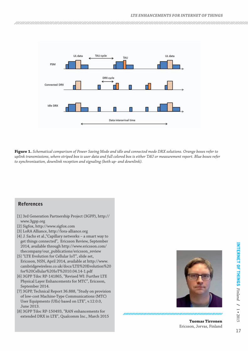
Figure 1 illustrates both PSM and idle and connected mode DRX solutions. In PSM, the signaling price of UE reachability in downlink is rather high, requiring RRC signaling accompanied by a TAU message, which is transmitted from UE to the core network node (MME). Because the reachability in downlink is tied to a periodic TAU cycle, PSM is best suited for uplink (mobile originating) traffic, or downlink traffic which is periodic with a known traffic pattern. For the extended DRX solutions, downlink reachability is achieved by either listening to downlink control channels (in connected mode) or paging messages (in idle mode), indicated by the small blue boxes in Figure 1. The DRX cycle can be flexibly configured to account for the use scenario. There is no extra signaling needed for downlink reachability with DRX. When UE wants to transmit in uplink, it can do so in any of the solutions at will. In PSM and idle mode DRX, the UE needs to first perform the RRC connection setup procedure, while in connected mode DRX the UE needs only to take care to have its air interface synchronized with the base station (eNB) before transmitting uplink data. Thus, from a signaling point of view, the connected mode DRX solution would be most desirable. However, in connected mode the UE needs to perform mobility measurements and may be configured with measurement reporting (orange boxes), resulting in more power consumed when not transmitting UL data compared to idle mode. It is still up for discussion which DRX cycle lengths will be possible to configure in Rel-13; the current work targets extensions for both idle and connected modes. The achievable lifetimes are similar to those with PSM, or more, as signaling traffic is saved with the DRX solutions. This means 10+ years of lifetime can be reached for the future LTE MTC devices where the downlink reachability can be flexibly adjusted uncoupled from the possible data reporting interval of the UE.
Table 1. Properties of some LTE UE categories. Adapted from [5].
Rel-8 Cat-4 UE Rel-8 Cat-1 UE Rel-12 Cat-0 UE Rel-13 low complexity (MTC) UE
Peak data rate (DL/UL) 150 / 50 Mbps 10 / 5 Mbps 1 / 1 Mbps 1 / 1 Mbps
Number of receiver antennas 2 2 1 1
Duplex mode (FDD) Full duplex Full duplex Optional half-duplex Optional half-duplex
UE RF bandwidth 20 MHz 20 MHz 20 MHz 1.4 MHz
Max. UE TX power 23 dBm 23 dBm 23 dBm 20 dBm
Projected relative complexity >100% 100% 50 % 25 %
(As a result, the) LTE air interface can achieve significant coverage improvement, making it possible to reach UEs in coverage-limited locations, such as basements
17
INT
ER
NE
T O
F T
HIN
GS
Finland / 1 • 2015LTE ENHANCEMENTS FOR INTERNET OF THINGS
References
[1] 3rd Generation Partnership Project (3GPP), http://www.3gpp.org
[2] Sigfox, http://www.sigfox.com[3] LoRA Alliance, http://lora-alliance.org[4] J. Sachs et al.,“Capillary networks – a smart way to
get things connected”, Ericsson Review, September 2014, available through http://www.ericsson.com/thecompany/our_publications/ericsson_review
[5] “LTE Evolution for Cellular IoT”, slide set, Ericsson, NSN, April 2014, available at http://www.cambridgewireless.co.uk/docs/LTE%20Evolution%20for%20Cellular%20IoT%2010.04.14-1.pdf
[6] 3GPP Tdoc RP-141865, “Revised WI: Further LTE Physical Layer Enhancements for MTC”, Ericsson, September 2014.
[7] 3GPP, Technical Report 36.888, “Study on provision of low-cost Machine-Type Communications (MTC) User Equipments (UEs) based on LTE”, v.12.0.0, June 2013.
[8] 3GPP Tdoc RP-150493, “RAN enhancements for extended DRX in LTE”, Qualcomm Inc., March 2015
Figure 1. Schematical comparison of Power Saving Mode and idle and connected mode DRX solutions. Orange boxes refer to uplink transmissions, where striped box is user data and full colored box is either TAU or measurement report. Blue boxes refer to synchronization, downlink reception and signaling (both up- and downlink).
Tuomas TirronenEricsson, Jorvas, Finland
18
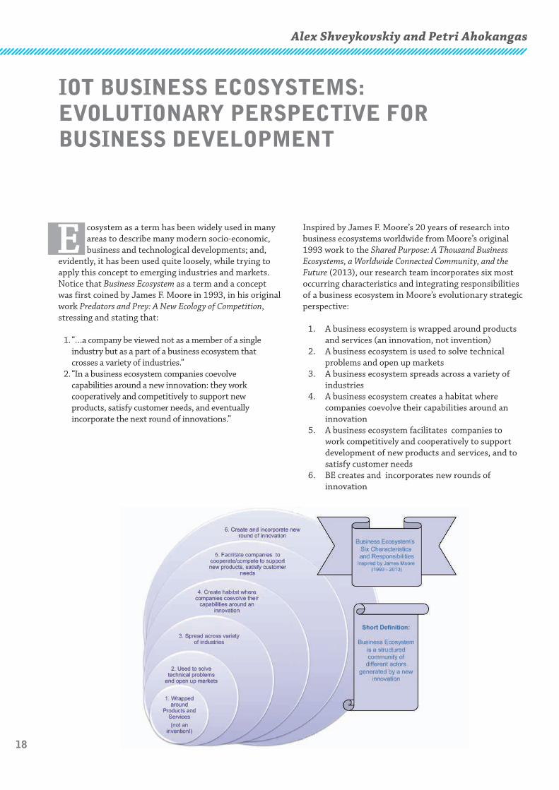
Inspired by James F. Moore’s 20 years of research into business ecosystems worldwide from Moore’s original 1993 work to the Shared Purpose: A Thousand Business Ecosystems, a Worldwide Connected Community, and the Future (2013), our research team incorporates six most occurring characteristics and integrating responsibilities of a business ecosystem in Moore’s evolutionary strategic perspective:
1. A business ecosystem is wrapped around products and services (an innovation, not invention)
2. A business ecosystem is used to solve technical problems and open up markets
3. A business ecosystem spreads across a variety of industries
4. A business ecosystem creates a habitat where companies coevolve their capabilities around an innovation
5. A business ecosystem facilitates companies to work competitively and cooperatively to support development of new products and services, and to satisfy customer needs
6. BE creates and incorporates new rounds of innovation
E cosystem as a term has been widely used in many areas to describe many modern socio-economic, business and technological developments; and,
evidently, it has been used quite loosely, while trying to apply this concept to emerging industries and markets. Notice that Business Ecosystem as a term and a concept was first coined by James F. Moore in 1993, in his original work Predators and Prey: A New Ecology of Competition, stressing and stating that:
1. “…a company be viewed not as a member of a single industry but as a part of a business ecosystem that crosses a variety of industries.”
2. “In a business ecosystem companies coevolve capabilities around a new innovation: they work cooperatively and competitively to support new products, satisfy customer needs, and eventually incorporate the next round of innovations.”
Alex Shveykovskiy and Petri Ahokangas
IOT BUSINESS ECOSYSTEMS: EVOLUTIONARY PERSPECTIVE FOR BUSINESS DEVELOPMENT
19
INT
ER
NE
T O
F T
HIN
GS
Finland / 1 • 2015
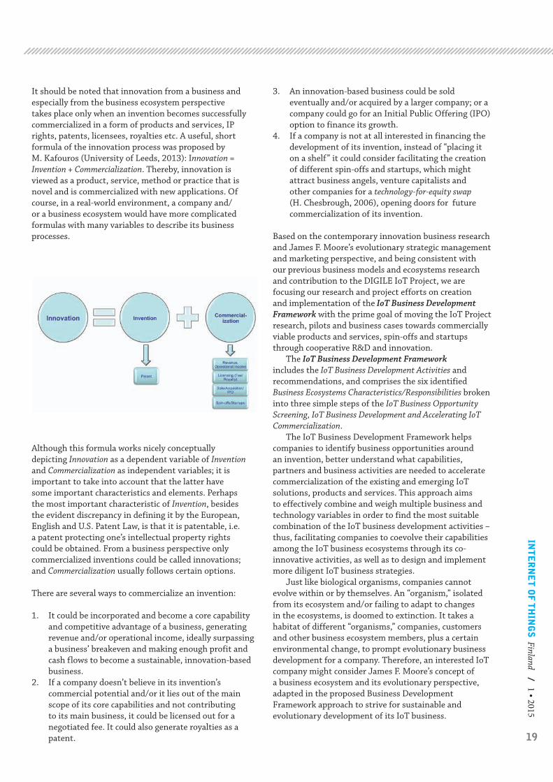
It should be noted that innovation from a business and especially from the business ecosystem perspective takes place only when an invention becomes successfully commercialized in a form of products and services, IP rights, patents, licensees, royalties etc. A useful, short formula of the innovation process was proposed by M. Kafouros (University of Leeds, 2013): Innovation = Invention + Commercialization. Thereby, innovation is viewed as a product, service, method or practice that is novel and is commercialized with new applications. Of course, in a real-world environment, a company and/or a business ecosystem would have more complicated formulas with many variables to describe its business processes.
Although this formula works nicely conceptually depicting Innovation as a dependent variable of Invention and Commercialization as independent variables; it is important to take into account that the latter have some important characteristics and elements. Perhaps the most important characteristic of Invention, besides the evident discrepancy in defining it by the European, English and U.S. Patent Law, is that it is patentable, i.e. a patent protecting one’s intellectual property rights could be obtained. From a business perspective only commercialized inventions could be called innovations; and Commercialization usually follows certain options.
There are several ways to commercialize an invention:
1. It could be incorporated and become a core capability and competitive advantage of a business, generating revenue and/or operational income, ideally surpassing a business’ breakeven and making enough profit and cash flows to become a sustainable, innovation-based business.
2. If a company doesn’t believe in its invention’s commercial potential and/or it lies out of the main scope of its core capabilities and not contributing to its main business, it could be licensed out for a negotiated fee. It could also generate royalties as a patent.
3. An innovation-based business could be sold eventually and/or acquired by a larger company; or a company could go for an Initial Public Offering (IPO) option to finance its growth.
4. If a company is not at all interested in financing the development of its invention, instead of “placing it on a shelf” it could consider facilitating the creation of different spin-offs and startups, which might attract business angels, venture capitalists and other companies for a technology-for-equity swap (H. Chesbrough, 2006), opening doors for future commercialization of its invention.
Based on the contemporary innovation business research and James F. Moore’s evolutionary strategic management and marketing perspective, and being consistent with our previous business models and ecosystems research and contribution to the DIGILE IoT Project, we are focusing our research and project efforts on creation and implementation of the IoT Business Development Framework with the prime goal of moving the IoT Project research, pilots and business cases towards commercially viable products and services, spin-offs and startups through cooperative R&D and innovation.
The IoT Business Development Framework includes the IoT Business Development Activities and recommendations, and comprises the six identified Business Ecosystems Characteristics/Responsibilities broken into three simple steps of the IoT Business Opportunity Screening, IoT Business Development and Accelerating IoT Commercialization.
The IoT Business Development Framework helps companies to identify business opportunities around an invention, better understand what capabilities, partners and business activities are needed to accelerate commercialization of the existing and emerging IoT solutions, products and services. This approach aims to effectively combine and weigh multiple business and technology variables in order to find the most suitable combination of the IoT business development activities – thus, facilitating companies to coevolve their capabilities among the IoT business ecosystems through its co-innovative activities, as well as to design and implement more diligent IoT business strategies.
Just like biological organisms, companies cannot evolve within or by themselves. An “organism,” isolated from its ecosystem and/or failing to adapt to changes in the ecosystems, is doomed to extinction. It takes a habitat of different “organisms,” companies, customers and other business ecosystem members, plus a certain environmental change, to prompt evolutionary business development for a company. Therefore, an interested IoT company might consider James F. Moore’s concept of a business ecosystem and its evolutionary perspective, adapted in the proposed Business Development Framework approach to strive for sustainable and evolutionary development of its IoT business.

20Alex Shveykovskiy and Petri Ahokangas
Oulu Business School, University of Oulu, Oulu, Finland
IoT Business Development Framework
Business Ecosystem IoT Business Development ActivitiesCharacteristics/ Responsibilities IoT Business IoT Business Accelerating IoT Opportunity Screening Development Commercialization
1.Products and Services Assess and develop your ideas by Protect, develop and turn you Compete with alternative (IoT Solutions) screening existing and emerging ideas into new products and implementations of similar IoT products and services services. Develop your core ideas Assess your core capabilities capabilities with your partners Focus and optimize your technology and businesswise Plan your Commercialization Commercialization Strategy, Strategy: Revenue/ operational consider both internal income; Sale/ acquisition/ IPO; and external Patent/ licensing – fee/royalty commercialization 2.Technology and Markets Decide which technical and Enter a market with a Bring your value proposition customer problems to solve and competitive value proposition, to a large market by working which markets it may open which benefits your Customers with partners, scale up, and achieve maximum market coverage Ensure that your approach becomes a market standard in its market segments 3.Industry Spread Screen, match and plan your Develop a compelling vision Build and maintain strong industry coverage of your value proposition to the bargaining power, build on industries your value proposition to Optimize your industry coverage the industries 4. Habitat of company Determine a habitat of companies Facilitate the habitat to coevolve Network critical leadcapabilities coevolution with the right capabilities for company capabilities around an partners, customers, andaround an innovation your innovation to work innovation important channels 5. Cooperation/ Competition Define your partners and Navigate and build a healthy Work with innovators tofor New Products and competitors, plan your cooperative balance between cooperative bring new ideas to theCustomers and competitive activities to and competitive activities existing ecosystem satisfy customer needs Maintain high barriers to entry Maintain high customer switching cost
6. New Round of Innovation Envision the next round of your Facilitate Open Innovation Plan and finance the next innovation activities Work with innovators internally round of innovation Study and attract potential and externally to facilitate Facilitate creation of new partners a new round of innovation Spin-offs and startups
IOT BUSINESS ECOSYSTEMS: EVOLUTIONARY PERSPECTIVE FORBUSINESS DEVELOPMENT

21
INT
ER
NE
T O
F T
HIN
GS
Finland / 1 • 2015Ali Hazmi, Muhammad Qutab-ud-din, Behnam Badihi, Parth Amin,
Luis Felipe Del Carpio, Anna Larmo, and Mikko Valkama
I. Introduction
T he IEEE 802.11ah is a new amendment of the IEEE 802.11 standard, suitable for high density and relatively short range devices (SRDs) and
WLAN networks [1]. The new amendment is based on the PHY and MAC designs of the state-of-the-art 802.11ac adapted to lower bandwidth operations. It is mainly targeting to fulfill the strict M2M and IoT requirements, while at the same time providing mechanisms that enable coexistence with other systems in the Sub-1 GHz bands including IEEE 802.15.4 (ZigBee). The development of this emerging technology is at its final stages and the complete standard is expected to be finalized in 2016. The 802.11ah is expected to be the dominant standard in many Internet of Things (IoT) and Machine-to-Machine (M2M) applications and their corresponding use cases.
The suitability study regarding the deployment of the IEEE 802.11ah technology in IoT and M2M applications confirmed its efficiency to fulfill the strict requirements of the use cases and the ability to operate well at the unlicensed Sub-1 GHz bands. For instance, the IEEE 802.11ah system represents an efficient radio technology for M2M applications [2-5] which is also able to extend the usability range up to1 km. Compared to other IEEE 802.11x technologies and other proprietary solutions like Bluetooth and ZigBee, the IEEE 802.11ah can achieve higher ranges due to the use of OFDM based
technology in the sub-1 GHz bands. Additionally, with the help of the newly introduced power saving mechanisms, IEEE 802.11ah can also noticeably reduce the energy consumption when compared to other existing technologies and increase further the amount of supported devices per Basic Service Set (BSS) [4].
Furthermore, the IEEE 802.11ah technology is considered as an important enabler of the Wideband SRDs (subset of the broader SRD family). It holds great potential to be a catalyst for further market growth in the IoT and M2M communication spheres, including smart-homes, building automation and other such applications. This can be accomplished in particular through advanced characteristics of these IEEE 802.11ah based devices such as higher data rates and improved power usage. Specifically, the IEEE 802.11ah technology is characterized by an efficient spectrum utilization of the limited available frequency bands, especially at the 863 - 868 MHz in EU and 902 - 928 MHz in US, where the IEEE 802.11ah is expected to be deployed.
These frequency bands are being regulated using different rules in Europe and US by ERC, ETSI, and FCC regulations bodies. These organizations set guidelines for example on the maximum allowed transmit power, on the channel spacing, and on the duty cycle for radio technologies deployed in these bands.
STUDY OF THE DUTY CYCLE CHALLENGES FOR SHORT RANGE DEVICES DEPLOYMENT BASED ON THE IEEE 802.11AH IN M2M AND IOT NETWORKS
Abstract- The Sub-1 GHz Wi-Fi standard is at its final state of development by the IEEE 802.11ah task group (TGah). Currently, the IEEE 802.11ah technology is considered as an important enabler of the wideband short range devices (SRDs) and addresses many use cases within the Internet of Things (IoT) and Machine-to-Machine (M2M) framework. Specially, it is characterized by an efficient spectrum utilization of unlicensed Industrial Scientific and Medical (ISM) bands where it is expected to be deployed. These bands are subject to different regulation domains according to geographical areas for example in Europe by ERC and ETSI and in the US by FCC which must be followed by all radio technologies deployed in these bands. The regulatory bodies set guidelines, for example on the maximum allowed transmit power, on the channel spacing, and on the maximum duty cycle. For instance, in Europe devices in Sub-1 GHz ISM bands must comply with the maximum duty cycle of 2.8% on the transmission time by devices performing Listen Before Talk (LBT) and Adaptive Frequency Agility (AFA). In this article we will mainly investigate the challenges of the duty cycle and its effect on the IEEE 802.11ah performance for an uplink transmission perspective considering typical use cases characterized by different traffic models. The preliminary reported results in this article show that for the most important IEEE 802.11ah use cases, as sensor IoT networks, smart grids and home building automation, and taking into account some assumptions regarding the network configurations and the traffic parameters, the maximum duty cycle limit of 2.8% doesn't represent a preventive challenge for the IEEE 802.11ah network deployment.

22
1. Duty Cycle for a single device case
For a simple IEEE 802.11ah network where only one device is sending data to its associated access point (AP), we can easily determine analytically the upper limit of the duty cycle D per device as follows. Figure 1 shows how data is typically transmitted between one station (STA) and one AP using IEEE 802.11ah basic scheme. The IEEE 802.11ah MAC timing parameters for 2 MHz mode are shown in Table 1.
Here we assume the following:• Point to point communication (STA <-> AP): only
one STA and one AP (no contention).• No re-transmissions are used: a given data packet
is transmitted only once.• We use a minimum contention window (CW) of
15 time slots. Consequently, the random back-off time will be chosen between 0 and 15 time slots, which results in an average of slots.
• Full buffer: The STA has always packet to be transmitted, i.e., Idle time = 0 seconds (if inter-frame time is not considered).
If we assume further that: – the basic modulation and coding scheme,MCS0, is used (≈ 0.65 Mbps) and – the size of data payload is 256 bytes
Then the duty cycle can be expressed as follows:
This is consequently the theoretical upper limit for the actual IEEE 802.11ah duty cycle when the smallest modulation and coding scheme are used. In Table 2 we include the theoretical upper limit duty cycle for different MCSs and DATA payload size.
2. Duty Cycle for a multiple stations case
If multiple STAs are present in the network, one can estimate the resulting duty cycle as the duty cycle of one STA time’s number of STAs in the network:
In this context and observing the regulation in Europe, Sub-1GHz ISM bands are subject to maximum duty cycle per device that prevents a given transmitter from occupying a channel for an extensive period of time. The limits on the maximum duty cycle are in the order of 0.1% for simple radio devices and to 2.8% for devices adhering to LBT and AFA. As IEEE 802.11ah is expected to be deployed in Sub-1 GHz ISM bands and assuming it is adhering to LBT and AFA, it needs to comply to a maximum duty cycle limitation per device. This affects the performance claimed by the IEEE 802.11ah specifications and has an effect on target use cases.
In this article we will mainly investigate the challenges of the maximum duty cycle and its effect on the IEEE 802.11ah performance. Typical use cases characterized by different traffic models will be considered in the study. The focus of the analysis is on the uplink duty cycle scenario.
II. Theoretical Upper Limit of IEEE 802.11ah Duty Cycle
In the literature the duty cycle D in a WLAN network is typically defined as the ratio of the active duration tactive(s) of a given device to the total duration ttot(s) of the WLAN signal:
D = 100. tactive
(1)
ttotal
Additionally, the duty cycle is usually defined per device, i.e., only the activity of a tagged device is concerned and not the whole network.
In principle the duty cycle is defined for a transmission cycle (ttotal) of one hour [6]. For simplicity we assume in this article that the total duration is variable and depends on the DATA payload and on the system timing parameters as given in equation (2).
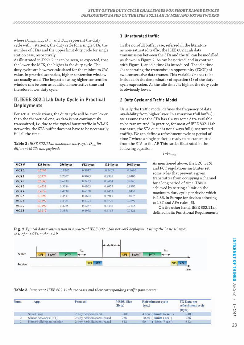
Fig.1 Typical data transmission in a simple IEEE 802.11ah network using the basic scheme: we assume uplink traffic where the STA continuously (full buffer case ) send DATA packets to the access point.
Table 1: IEEE 802.11ah Timing parameters (2 MHz mode)
23
INT
ER
NE
T O
F T
HIN
GS
Finland / 1 • 2015
1. Unsaturated traffic
In the non-full buffer case, referred in the literature as non-saturated traffic, the IEEE 802.11ah data transmission between the STA and the AP can be modelled as shown in Figure 2. As can be noticed, and in contrast with Figure 1, an idle time I is introduced. The idle time I is separating the transmission opportunity (TXOP) of two consecutive data frames. This variable I needs to be included in the denominator of equation (1) of the duty cycle expression. As the idle time I is higher, the duty cycle is obviously lower.
2. Duty Cycle and Traffic Model
Usually the traffic model defines the frequency of data availability from higher layer. In saturation (full buffer), we assume that the STA has always some data available to be transmitted. In practice, for most of IEEE 802.11ah use cases, the STA queue is not always full (unsaturated traffic). We can define a refreshment cycle or period of time T where a single packet is ready to be transmitted from the STA to the AP. This can be illustrated in the following equation:
T=I+ttotal
As mentioned above, the ERC, ETSI, and FCC regulations institutes set some rules that prevent a given transmitter from occupying a channel for a long period of time. This is achieved by setting a limit on the maximum duty cycle per device which is 2.8% in Europe for devices adhering to LBT and AFA rules [6].
On the other hand, IEEE 802.11ah defined in its Functional Requirements
where Dmultiplestations, D, n, and Dmax represent the duty cycle with n stations, the duty cycle for a single STA, the number of STAs and the upper limit duty cycle for single station case, respectively.As illustrated in Table 2, it can be seen, as expected, that the lower the MCS, the higher is the duty cycle. The duty cycles are however calculated for the minimum CW value. In practical scenarios, higher contention window are usually used. The impact of using higher contention window can be seen as additional non-active time and therefore lower duty cycle.
II. IEEE 802.11ah Duty Cycle in Practical Deployments
For actual applications, the duty cycle will be even lower than the theoretical one, as data is not continuously transmitted, i.e. due to the typical burst traffic in WLAN networks, the STA buffer does not have to be necessarily full all the time.
Table 2: IEEE 802.11ah maximum duty cycle Dmax for different MCSs and payloads
STUDY OF THE DUTY CYCLE CHALLENGES FOR SHORT RANGE DEVICES DEPLOYMENT BASED ON THE IEEE 802.11AH IN M2M AND IOT NETWORKS
Fig. 2 Typical data transmission in a practical IEEE 802.11ah network deployment using the basic scheme: case of one STA and one AP
Table 3: Important IEEE 802.11ah use cases and their corresponding traffic parameters
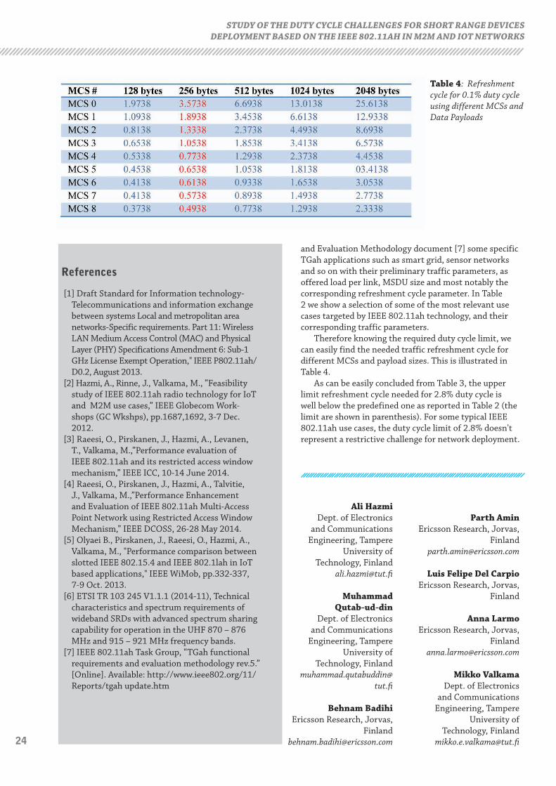
24
Ali HazmiDept. of Electronics
and Communications Engineering, Tampere
University of Technology, Finland
Muhammad Qutab-ud-din
Dept. of Electronics and Communications
Engineering, Tampere University of
Technology, Finlandmuhammad.qutabuddin@
tut.fi
Behnam Badihi Ericsson Research, Jorvas,
Finland [email protected]
Parth Amin Ericsson Research, Jorvas,
Finland [email protected]
Luis Felipe Del Carpio Ericsson Research, Jorvas,
Finland
Anna LarmoEricsson Research, Jorvas,
Mikko ValkamaDept. of Electronics
and Communications Engineering, Tampere
University of Technology, Finland
STUDY OF THE DUTY CYCLE CHALLENGES FOR SHORT RANGE DEVICES DEPLOYMENT BASED ON THE IEEE 802.11AH IN M2M AND IOT NETWORKS
References
[1] Draft Standard for Information technology-Telecommunications and information exchange between systems Local and metropolitan area networks-Specific requirements. Part 11: Wireless LAN Medium Access Control (MAC) and Physical Layer (PHY) Specifications Amendment 6: Sub-1 GHz License Exempt Operation," IEEE P802.11ah/D0.2, August 2013.
[2] Hazmi, A., Rinne, J., Valkama, M., ”Feasibility study of IEEE 802.11ah radio technology for IoT and M2M use cases,” IEEE Globecom Work-shops (GC Wkshps), pp.1687,1692, 3-7 Dec. 2012.
[3] Raeesi, O., Pirskanen, J., Hazmi, A., Levanen, T., Valkama, M.,”Performance evaluation of IEEE 802.11ah and its restricted access window mechanism,” IEEE ICC, 10-14 June 2014.
[4] Raeesi, O., Pirskanen, J., Hazmi, A., Talvitie, J., Valkama, M.,”Performance Enhancement and Evaluation of IEEE 802.11ah Multi-Access Point Network using Restricted Access Window Mechanism,” IEEE DCOSS, 26-28 May 2014.
[5] Olyaei B., Pirskanen, J., Raeesi, O., Hazmi, A., Valkama, M., "Performance comparison between slotted IEEE 802.15.4 and IEEE 802.1lah in IoT based applications," IEEE WiMob, pp.332-337, 7-9 Oct. 2013.
[6] ETSI TR 103 245 V1.1.1 (2014-11), Technical characteristics and spectrum requirements of wideband SRDs with advanced spectrum sharing capability for operation in the UHF 870 – 876 MHz and 915 – 921 MHz frequency bands.
[7] IEEE 802.11ah Task Group, “TGah functional requirements and evaluation methodology rev.5.” [Online]. Available: http://www.ieee802.org/11/Reports/tgah update.htm
Table 4: Refreshment cycle for 0.1% duty cycle using different MCSs and Data Payloads
and Evaluation Methodology document [7] some specific TGah applications such as smart grid, sensor networks and so on with their preliminary traffic parameters, as offered load per link, MSDU size and most notably the corresponding refreshment cycle parameter. In Table 2 we show a selection of some of the most relevant use cases targeted by IEEE 802.11ah technology, and their corresponding traffic parameters.
Therefore knowing the required duty cycle limit, we can easily find the needed traffic refreshment cycle for different MCSs and payload sizes. This is illustrated in Table 4.
As can be easily concluded from Table 3, the upper limit refreshment cycle needed for 2.8% duty cycle is well below the predefined one as reported in Table 2 (the limit are shown in parenthesis). For some typical IEEE 802.11ah use cases, the duty cycle limit of 2.8% doesn't represent a restrictive challenge for network deployment.
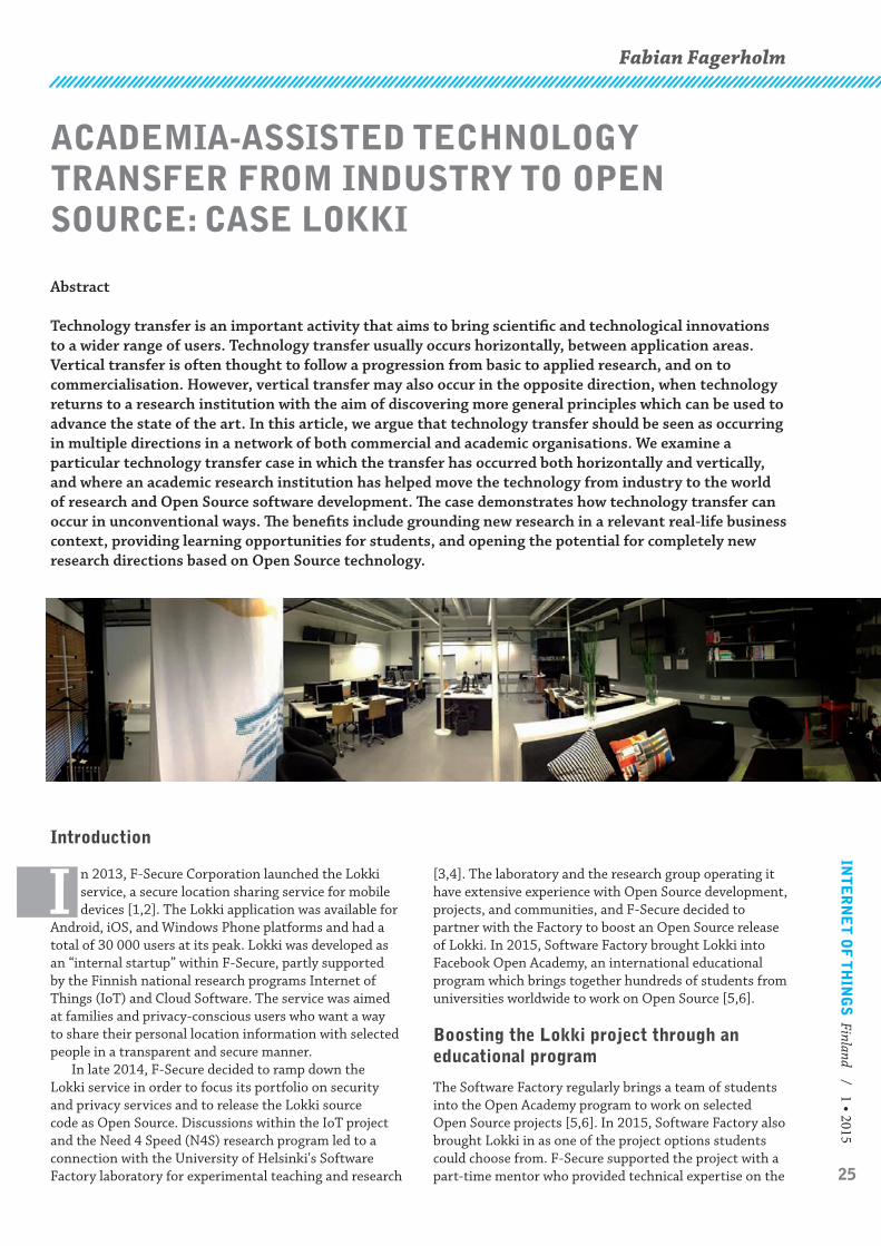
25
INT
ER
NE
T O
F T
HIN
GS
Finland / 1 • 2015
Fabian Fagerholm
[3,4]. The laboratory and the research group operating it have extensive experience with Open Source development, projects, and communities, and F-Secure decided to partner with the Factory to boost an Open Source release of Lokki. In 2015, Software Factory brought Lokki into Facebook Open Academy, an international educational program which brings together hundreds of students from universities worldwide to work on Open Source [5,6].
Boosting the Lokki project through an educational program
The Software Factory regularly brings a team of students into the Open Academy program to work on selected Open Source projects [5,6]. In 2015, Software Factory also brought Lokki in as one of the project options students could choose from. F-Secure supported the project with a part-time mentor who provided technical expertise on the
Introduction
I n 2013, F-Secure Corporation launched the Lokki service, a secure location sharing service for mobile devices [1,2]. The Lokki application was available for
Android, iOS, and Windows Phone platforms and had a total of 30 000 users at its peak. Lokki was developed as an “internal startup” within F-Secure, partly supported by the Finnish national research programs Internet of Things (IoT) and Cloud Software. The service was aimed at families and privacy-conscious users who want a way to share their personal location information with selected people in a transparent and secure manner.
In late 2014, F-Secure decided to ramp down the Lokki service in order to focus its portfolio on security and privacy services and to release the Lokki source code as Open Source. Discussions within the IoT project and the Need 4 Speed (N4S) research program led to a connection with the University of Helsinki's Software Factory laboratory for experimental teaching and research
ACADEMIA-ASSISTED TECHNOLOGY TRANSFER FROM INDUSTRY TO OPEN SOURCE: CASE LOKKI
Abstract
Technology transfer is an important activity that aims to bring scientific and technological innovations to a wider range of users. Technology transfer usually occurs horizontally, between application areas. Vertical transfer is often thought to follow a progression from basic to applied research, and on to commercialisation. However, vertical transfer may also occur in the opposite direction, when technology returns to a research institution with the aim of discovering more general principles which can be used to advance the state of the art. In this article, we argue that technology transfer should be seen as occurring in multiple directions in a network of both commercial and academic organisations. We examine a particular technology transfer case in which the transfer has occurred both horizontally and vertically, and where an academic research institution has helped move the technology from industry to the world of research and Open Source software development. The case demonstrates how technology transfer can occur in unconventional ways. The benefits include grounding new research in a relevant real-life business context, providing learning opportunities for students, and opening the potential for completely new research directions based on Open Source technology.

26
Lokki code base. Students at the University of Helsinki, MIT, and University of Illinois at Urbana-Champaign signed up for the project. Each university worked according to their own schedule and local curriculum, but met in person during a co-located Code Sprint event at Facebook's headquarters in Menlo Park, California.
Software Factory students, mentor, and coach visiting Facebook HQ in Menlo Park, California.
The work environment in the Software Factory mimics a real software development company or startup. Students work on premise at the Factory, four or five days per week and an average of six hours per day. This intensive schedule ensures a steady pace for the project and means students can set quite ambitious goals. It also means they encounter real problems that provide ample opportunity for learning and applying theoretical knowledge they have acquired earlier.
Apart from the benefit to students, the Software Factory also provided an opportunity to boost the introduction of Lokki into the world of Open Source. With assistance and direction from Factory staff, they set up a modern Open Source development environment, with version control on GitHub, continuous integration on Travis CI, and backend deployment on Heroku, as well as communication channels on Google Groups, Slack, and IRC. Such infrastructure for handling code, deployment, and communication is vital for any Open Source project.
Preparing Lokki for future development
Setting up the project infrastructure is a prerequisite for development, but so is preparing the code base for fast-paced development. Source code can rarely be improved so widely and deeply as in the beginning of a project, when no existing deployments need to be taken into account and development of new features takes up most of the developer resources. During the first few weeks of the project, the student team examined the code of the Lokki backend – written in Node.js – and the Android client. They refactored code, used static analysis and linter checks to find code style inconsistencies and other flaws, and updated the code to use newer API versions.
With the updated and polished code base, Lokki was ready for a few new features. Updating the Android client user interface to use the new “Material design” was one of the overall improvements, as well as adding some small new features that the team felt were missing for the service to be usable. A re-release of the Lokki service as an Open Source application in app stores was now possible.
The Software Factory facility at the Department of Computer Science, University of Helsinki.
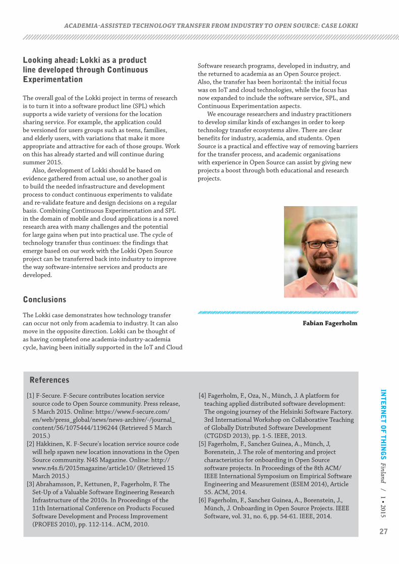
27
INT
ER
NE
T O
F T
HIN
GS
Finland / 1 • 2015
Looking ahead: Lokki as a product line developed through Continuous Experimentation
The overall goal of the Lokki project in terms of research is to turn it into a software product line (SPL) which supports a wide variety of versions for the location sharing service. For example, the application could be versioned for users groups such as teens, families, and elderly users, with variations that make it more appropriate and attractive for each of those groups. Work on this has already started and will continue during summer 2015.
Also, development of Lokki should be based on evidence gathered from actual use, so another goal is to build the needed infrastructure and development process to conduct continuous experiments to validate and re-validate feature and design decisions on a regular basis. Combining Continuous Experimentation and SPL in the domain of mobile and cloud applications is a novel research area with many challenges and the potential for large gains when put into practical use. The cycle of technology transfer thus continues: the findings that emerge based on our work with the Lokki Open Source project can be transferred back into industry to improve the way software-intensive services and products are developed.
Conclusions
The Lokki case demonstrates how technology transfer can occur not only from academia to industry. It can also move in the opposite direction. Lokki can be thought of as having completed one academia-industry-academia cycle, having been initially supported in the IoT and Cloud
References
[1] F-Secure. F-Secure contributes location service source code to Open Source community. Press release, 5 March 2015. Online: https://www.f-secure.com/en/web/press_global/news/news-archive/-/journal_content/56/1075444/1196244 (Retrieved 5 March 2015.)
[2] Häkkinen, K. F-Secure's location service source code will help spawn new location innovations in the Open Source community. N4S Magazine. Online: http://www.n4s.fi/2015magazine/article10/ (Retrieved 15 March 2015.)
[3] Abrahamsson, P., Kettunen, P., Fagerholm, F. The Set-Up of a Valuable Software Engineering Research Infrastructure of the 2010s. In Proceedings of the 11th International Conference on Products Focused Software Development and Process Improvement (PROFES 2010), pp. 112-114.. ACM, 2010.
[4] Fagerholm, F., Oza, N., Münch, J. A platform for teaching applied distributed software development: The ongoing journey of the Helsinki Software Factory. 3rd International Workshop on Collaborative Teaching of Globally Distributed Software Development (CTGDSD 2013), pp. 1-5. IEEE, 2013.
[5] Fagerholm, F., Sanchez Guinea, A., Münch, J, Borenstein, J. The role of mentoring and project characteristics for onboarding in Open Source software projects. In Proceedings of the 8th ACM/IEEE International Symposium on Empirical Software Engineering and Measurement (ESEM 2014), Article 55. ACM, 2014.
[6] Fagerholm, F., Sanchez Guinea, A., Borenstein, J., Münch, J. Onboarding in Open Source Projects. IEEE Software, vol. 31, no. 6, pp. 54-61. IEEE, 2014.
Software research programs, developed in industry, and the returned to academia as an Open Source project. Also, the transfer has been horizontal: the initial focus was on IoT and cloud technologies, while the focus has now expanded to include the software service, SPL, and Continuous Experimentation aspects.
We encourage researchers and industry practitioners to develop similar kinds of exchanges in order to keep technology transfer ecosystems alive. There are clear benefits for industry, academia, and students. Open Source is a practical and effective way of removing barriers for the transfer process, and academic organisations with experience in Open Source can assist by giving new projects a boost through both educational and research projects.
Fabian Fagerholm
ACADEMIA-ASSISTED TECHNOLOGY TRANSFER FROM INDUSTRY TO OPEN SOURCE: CASE LOKKI
28
Teemu Leppänen and Jukka Riekki
MOVING COMPUTATION TO THE EDGES OF IOT
Recently, several big companies have brought forward how the industrial IoT sensor-equipped devices produce increasing amounts of real-time data, to the extent of referring to the situation as “data onslaught”. Consequently, questions have been raised. Are most of the IoT communications a roundtrip to servers in the back end? Should we retain only the relevant data on the back-end system? How do we make local decisions at the data source of which data are discarded and which are retained?
In our work, we have studied local data processing at the very edges of IoT networks. Our focus is on low-power resource-constrained embedded IoT devices, where reducing the communications cost is crucial to extending the lifetime of the devices. We utilize a well-known distributed systems application design paradigm, the mobile agent, to move and distribute application-specific task code between the devices of an IoT system. Mobile agents are autonomous programs that are able to communicate, and control their own execution and movement in networked systems. The amount of transmitted data can be reduced by mobile agents that, based on the requirements of the application, perform context-aware data filtering and local event detection at the data source. Moreover, resources in the device, such as remaining battery level, can be taken into account when decisions about the task execution are made. The overall energy consumption can be optimized by partitioning the communication and computation load into the system with mobile agents that cooperatively share their task results with other agents and non-agent entities. With these capabilities, mobile agents can adapt to changes in their environment and in network conditions.
Our real-world mobile-agent-based IoT application prototypes demonstrate interoperability with heterogeneous resource-constrained IoT devices: smartphones and 8-bit microcontroller-based embedded devices at the low end. Based on this preliminary work, we believe mobile agents could provide one solution to the questions raised.
Introduction
A t the TiEcon2014 conference, a number of big companies expressed a common need, particularly in industrial IoT, to reduce the
amount of data transferred from the field1. In their keynote, GE sees future technical differentiation in “decision making, learning which data to forget/discard and which data to retain/remember” and “the context of the data is becoming more important than the data itself”. Cisco believes “decision-making is needed at the network edge, to only send relevant [incoming real-time] data to the cloud for processing”. Moreover, the companies see a need for open standardization that focuses on interoperability issues in IoT. Qualcomm’s message was that “successful IoT architecture will be more complex than client/server computing”.
In industrial IoT, this need to reduce the communication load by processing large amounts of data at the network edges is easy to understand, but the same challenges apply generally in other IoT application scenarios “in the wild”. Sensor-equipped IoT devices, and generally embedded networked systems, have small in-device memory and limited communication capabilities. Most of their energy is consumed in communications, sending data to the back-end system. Processing and filtering data right at the source would reduce
communication costs and enable extracting application-specific (i.e. context-aware) features from the data. Moreover, this would enable reacting to events in real time in the device and sharing the information in direct communication between devices, without the “traditional” roundtrip to the back-end system.
Moving computation (i.e. code) to the edges of a network is not a new idea. In distributed systems, executable programs have been sent from servers to clients for decades. On the Web, well-known examples include JavaScript programs and Flash animations that run in users’ browsers. MapReduce is an example of distributing parallelizable tasks to a geographically extended grid of computers. In cloud computing, “cloudlets” distribute the data and computing resources to the infrastructure near mobile devices, where resource-intensive tasks can be offloaded from the devices. For large-scale distributed systems, server farms have been deployed to move applications away from centralized locations. Peer-to-peer computing in general distributes and partitions tasks between peers.
At the low-end of IoT devices, such as wireless sensor networks (WSN) deployed as embedded networked devices to the edges of the network, updating the software introduces a challenge. Clearly, it is not practical to

29
INT
ER
NE
T O
F T
HIN
GS
Finland / 1 • 2015
reprogram large numbers of geographically dispersed devices manually. “Over-the-air programming” refers to sending (and forcing) software updates from a central location to a set of distributed devices in range. Java-based OSGi specifies a software framework to deploy code remotely into the system components. Current implementations include mobile phones and application servers. Smartphone operating systems and software frameworks nowadays support “tasking applications”, where complex tasks are written in high-level (often application-specific) scripting language. The framework then distributes the tasks to a set of smartphones. These scripting languages aim at easing task development by providing high-level programming abstractions, but on the other hand may lack in expressive power.
Mobile agents are computer programs that control their own execution and decide about their movement (i.e. migration) between hosting devices in networked systems. A mobile agent includes its task (code or reference to the code), some data that the task requires and the current result of the task, which are transmitted as a single unit (i.e. message). Once a mobile agent has been injected into the system, it executes its task autonomously and asynchronously. Therefore, the originating component does not need to control the mobile agents’ operations. When a device receives a mobile agent, it decodes the message to a runnable code unit, runs the code, updates the agent state, composes the agent back to a message and sends it further according to its application-specific migration policy. Conceptually, the above-mentioned methods move tasks away from servers closer to clients, whereas mobile agents autonomously decide about when and where their tasks are executed. Example WSN applications for mobile agents include distributed data queries, data aggregation, data filtering and event detection. In computer networks, mobile agents have been used for route discovery and maintaining network topology. Mobile agents are useful in system
administration, for monitoring system or component states, and for fault detection. In pervasive computing, mobile agents have been used for context-aware personalization of the user’s environment, for example.
Extending this concept, several mobile agents can communicate and cooperate dynamically as an interoperable multi-agent system, where the output of one agent is the input of another. Figure 1 illustrates the general IoT system with stationary and mobile devices, where users and software components inject mobile agents into the system, whicht are then executed cooperatively in the devices. The “traditional” IoT approach would be data upload from the devices to the back-end, either directly over the Internet or through gateways. Then the refined data on the back end would be separately accessed by clients (some of which may be the same devices).
Common IoT system architecture
In IoT, we are concerned with interconnected subsystems, loosely coupled system components and heterogeneous devices that operate over disparate networks with different communication technologies. Thus, standardized communication protocols are required with uniform interfaces to provide seamless interoperability. Moreover, constrained IoT devices introduce their own requirements, such as small communication overhead and lightweight in-network services. To address these challenges and to enable mobile agent operation in IoT, we have adopted resource-oriented system architecture [1] that is based on the REST architectural style. We follow the IETF CoRE Working Group2 framework for constrained IP networks that realize embedded Web services for embedded devices, such as 8-bit microcontrollers. Figure 2 illustrates this architecture with heterogeneous IoT devices, both mobile (e.g. smartphones communicating with HTTP atop Wi-Fi) and stationary (e.g. WSN nodes communicating with CoAP2 atop 6LoWPAN). HTTP and CoAP protocols provide similar well-defined communication primitives that can be applied universally in communications.
Resource Directory stores system resource descriptions and provides a common interface to look up resources. For mobile agents, these resources include IoT devices as platforms to run the tasks, their components (such as physical and virtual sensors) and the data from the sensors. As IoT systems are in continuous transition, the directory is updated in runtime. Proxy components are needed for protocol translation and abstraction of the separate (sub)systems with the uniform interface. A Web application communicating with HTTP can access seamlessly through the proxy the resources in the WSN that, in turn, communicates with CoAP. Moreover, proxies can be introduced to conceal with their exposed interface the details of application-specific functionality or service compositions. As an example, we have integrated the Code Repository component for the mobile agents into the proxy.
Figure 1: The IoT playground for mobile agents

30
The internals of mobile agents
The mobile agent composition, that is, the data structure that actually is the mobile agent, contains three separated segments [1]: code, resource and state. The composition must be as general as possible, to cope with the heterogeneous devices with different operating systems and hardware platforms. Each mobile agent has a name and its address is the current address of the hosting device. This address is updated into the resource directory each time the agent migrates, so that other components can locate the agent. HTTP and CoAP methods are utilized to access the mobile agent’s task results, to control its operation and to remove the agent from the system [1]. Moreover, the mobile agent itself communicates by the same methods with the other system components.
The code segment contains one or more versions of the agent task code with identifiers for the targeted platforms [1]. This way any programming language(s) can be included in the segment although including the task code in multiple languages may increase the composition out of reach for constrained embedded devices. Examples here include bytecode and common scripting languages, such as JavaScript and Python [1]. The resource segment lists the resources needed by the mobile agent. A resource can be an IoT device, its physical components and the data it produces. These resources can be accessed through the REST-based interfaces and, in case of a physical component, also actuated. Moreover, mobile agents’ results are also system resources and are accessed with the same interface as any other system resource. The state segment represents the agent as a system resource for other system components. Whenever other components access a mobile agent through its URL, this state is returned. In addition to the current result of the task, this segment can contain metadata related to the agent or its execution. Such mobile agents are seamlessly connected to IoT and can be utilized with the same interfaces as
universal RESTful Web services on the Internet today. The Web also facilitates human-machine interactions.
Once a programmer has written a mobile agent-based task for an IoT application, its required resources in the system (e.g. data) are located and their references added to the composition. With the task code and these resource references, a mobile agent composition is then injected into the system. How the resources are handled by a mobile agent depends on the task at hand, resource availability, capabilities of hosting devices and network conditions. In trying to reduce the communication costs, mobile agents can decide either to download a resource into the current host device or decide to migrate into the resource’s host. For example, migration can be more energy-efficient due to the resource size. This decision-making capability and adaptive operation are the benefits with mobile agents though optimizing their operations can be challenging – as is demonstrated in the literature. Another challenge with mobile agents is security, as the agent must be authenticated and appropriate behavior must be ensured for task execution and resource access.
IoT mobile agent applications
With mobile agents, we move the data processing tasks to network edges. The amount of energy consumed in communication is reduced by transmitting only the data that the applications are interested in to the back end. Mobile agents react to events in real time in the location, which facilitates realizing monitoring tasks. Mobile agents can actuate a physical component attached to the hosting device (or for that matter, another device in the network). If the host device is running out of its battery, or the user leaves the task location, a mobile agent can migrate away from that device. Here we describe some of our prototype mobile agent-based IoT applications.
As a simple prototype, we demonstrated mobile agent-based interoperability of heterogeneous WSN nodes over disparate networks in [2]. We utilized the system architecture in Figure 2 with mobile and stationary devices. The application is based on two mobile agents, the first migrates between all nodes to collect ambient lighting data of the immediate environment and the second one migrates between mobile nodes, collecting device localization data; Wi-Fi access pointsignal strengths and magnetometer sensor data. From this data, the coarse physical location of the mobile node is determined. When a mobile device comes to the proximity of a static node, the mobile node’s ambient light sensing is turned off by the mobile agent to save its battery. A Web application then visualizes the operations of mobile agents in the system through their states. Here, mobile agents remove redundancy in data collection and help the resource-constrained nodes to save energy by cooperation.
In the second application, we demonstrate mobile agents in an augmented reality (AR) application [3]. As shown in Figure 3, a mobile agent migrates into a WSN node to monitor the power consumption of a coffee
MOVING COMPUTATION TO THE EDGES OF IOT
Figure 2: System architecture to enable mobile agents
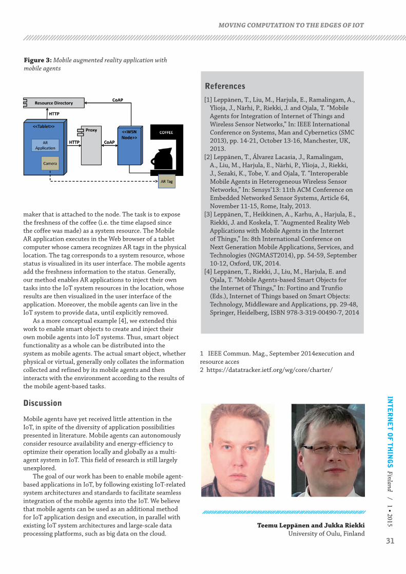
31
INT
ER
NE
T O
F T
HIN
GS
Finland / 1 • 2015
maker that is attached to the node. The task is to expose the freshness of the coffee (i.e. the time elapsed since the coffee was made) as a system resource. The Mobile AR application executes in the Web browser of a tablet computer whose camera recognizes AR tags in the physical location. The tag corresponds to a system resource, whose status is visualized in its user interface. The mobile agents add the freshness information to the status. Generally, our method enables AR applications to inject their own tasks into the IoT system resources in the location, whose results are then visualized in the user interface of the application. Moreover, the mobile agents can live in the IoT system to provide data, until explicitly removed.
As a more conceptual example [4], we extended this work to enable smart objects to create and inject their own mobile agents into IoT systems. Thus, smart object functionality as a whole can be distributed into the system as mobile agents. The actual smart object, whether physical or virtual, generally only collates the information collected and refined by its mobile agents and then interacts with the environment according to the results of the mobile agent-based tasks.
Discussion
Mobile agents have yet received little attention in the IoT, in spite of the diversity of application possibilities presented in literature. Mobile agents can autonomously consider resource availability and energy-efficiency to optimize their operation locally and globally as a multi-agent system in IoT. This field of research is still largely unexplored.
The goal of our work has been to enable mobile agent-based applications in IoT, by following existing IoT-related system architectures and standards to facilitate seamless integration of the mobile agents into the IoT. We believe that mobile agents can be used as an additional method for IoT application design and execution, in parallel with existing IoT system architectures and large-scale data processing platforms, such as big data on the cloud.
References
[1] Leppänen, T., Liu, M., Harjula, E., Ramalingam, A., Ylioja, J., Närhi, P., Riekki, J. and Ojala, T. “Mobile Agents for Integration of Internet of Things and Wireless Sensor Networks,” In: IEEE International Conference on Systems, Man and Cybernetics (SMC 2013), pp. 14-21, October 13-16, Manchester, UK, 2013.
[2] Leppänen, T., Álvarez Lacasia, J., Ramalingam, A., Liu, M., Harjula, E., Närhi, P., Ylioja, J., Riekki, J., Sezaki, K., Tobe, Y. and Ojala, T. “Interoperable Mobile Agents in Heterogeneous Wireless Sensor Networks,” In: Sensys’13: 11th ACM Conference on Embedded Networked Sensor Systems, Article 64, November 11-15, Rome, Italy, 2013.
[3] Leppänen, T., Heikkinen, A., Karhu, A., Harjula, E., Riekki, J. and Koskela, T. “Augmented Reality Web Applications with Mobile Agents in the Internet of Things,” In: 8th International Conference on Next Generation Mobile Applications, Services, and Technologies (NGMAST2014), pp. 54-59, September 10-12, Oxford, UK, 2014.
[4] Leppänen, T., Riekki, J., Liu, M., Harjula, E. and Ojala, T. “Mobile Agents-based Smart Objects for the Internet of Things,” In: Fortino and Trunfio (Eds.), Internet of Things based on Smart Objects: Technology, Middleware and Applications, pp. 29-48, Springer, Heidelberg, ISBN 978-3-319-00490-7, 2014
MOVING COMPUTATION TO THE EDGES OF IOT
Figure 3: Mobile augmented reality application with mobile agents
Teemu Leppänen and Jukka Riekki University of Oulu, Finland
1 IEEE Commun. Mag., September 2014execution and resource acces2 https://datatracker.ietf.org/wg/core/charter/

32
part of the system, we implemented a proof-of-concept demonstrator for a sensor vest with integrated wireless charging.
System Overview
The overall system design consists of various complementary service components:
• Building the safety vest design with gateway and appropriate sensors.
• Based on the participatory co-design process, building a situation-aware safety service for securing and enhancing the independent mobility of schoolchildren.
• Piloting the situation-aware safety services with different technical enablers.
• The proof-of-concept for integrated wireless charging, to bring the energy-efficiency to the sensor system.
For our safety vest prototype shown in Figure 1a, two slightly different platforms were utilized and compared: the LilyPad Arduino simple board and Adafruit’s Flora board. Both are micro-controller boards designed for wearables and e-textiles. These boards are used for integrating and collecting data from sensors and sending it wirelessly through the radio module to the gateway device. The vest includes GPS, accelerometer and temperature sensors, and an XBee radio. The components
Introduction
T he success of the new Internet of Things services and devices is greatly dependent on how well the end-user requirements, needs, and desires
are being met. Do the new solutions unobtrusively fit the users’ everyday usage contexts, and do they provide value for the users? It is critical that the appropriate end-users are involved in the development work of the new technological solutions throughout the different design stages. However, especially children are many times being neglected as technology end users, although there is a growing need for easily deployable and autonomous technical devices that support children’s safety and wellbeing. To ensure good user experiences, it is essential to gain an understanding of end-user needs early enough, and to turn this insight into user requirements.
In our work, we have developed a wearable sensor vest with wireless integrated charging to enhance the security of children. Our solution provides a comprehensive end-to-end solution ranging from energy-efficiency and usability to the extensive service framework. In the beginning of the design process, we carried out an associated participatory study among children, parents, and teachers in a primary school environment in Kempele, Finland, to gain knowledge about real user needs. In order to improve the safety and well-being services for children in the future, we piloted an end-to-end safety solution with similar technological characteristics as the vest. To evaluate the technical feasibility of the wearable
WEARABLE SENSOR VEST WITH WIRELESS CHARGING – AN ENERGY-EFFICIENT SAFETY SOLUTION FOR CHILDREN
Abstract
Mobile and wearable sensors are increasingly becoming our everyday life in monitoring and controlling health, well-being and security. Our work presents the technological enablers and requirements for building a complete end-to-end energy-efficient system for improving and controlling safety issues for children in day-care centers and schools. We designed a proof-of-concept for a wearable sensor vest with integrated wireless charging that takes place in the ordinary repository for the vests, such as in a wardrobe or a coat rack, without requiring any specific actions from the user. The developed sensor vest provides information about the location and well-being of children, based on received signal strength indication (RSSI), global positioning system (GPS), accelerometer, and temperature sensors. Teachers and parents are able to receive alerts and notifications, e.g., when a child moves across a certain restricted outdoor or indoor area, through gateways that have connectivity to a server or cloud. Piloting and technological implementations are based on a participatory study conducted among children, teachers, and parents, to gain important knowledge and understanding about the real user needs and service system usability requirements. The vest is part of a larger framework to provide digital safety applications and services through various sensor devices.
Mirjami Jutila, Esko Strömmer, Mari Ervasti, Mika Hillukkala, Pekka Karhula and Juhani Laitakari

33
INT
ER
NE
T O
F T
HIN
GS
Finland / 1 • 2015
are connected and sewn together on the fabric with a conductive thread, as shown in Figure 1c. The gateways/routers were implemented using Raspberry Pi and Intel’s Galileo, which are small computers suitable for covering mainly indoor but also limited outdoor spaces, because of both their size and cost. The gateway provides the basic set of functions to work as an Internet of Things (IoT) gateway to deliver the data to our safety service working on the Internet. Detecting whether the child's location is inside the allowed indoor area is based on the XBee radio range covered by the gateway(s). The location calculation was based on the received signal strength indicator (RSSI), using an algorithm that is based on the weighted centroid localization method. The location is weighted towards the gateway(s) that receive the best RSSI, and thus the algorithm robustly gives us a rough estimation of the area where the vest is. In outdoor areas the GPS is being utilized to get the exact location information.
The participatory co-design process revealed information about users’ needs, values, fears and expectations what the safety service for children should include and obtain. The gathered feedback gave valuable insights from children, their parents and teachers, regarding the “monitoring” of the child on a situation basis. This redirected the design of location-aware safety solutions so that they truly responded to end-user needs, fitted to users’ everyday usage contexts, and provided value for the targeted users. The developed safety service GUI (graphical user interface) for pupils’ teachers and parents, through which they could monitor the child’s last known locations is presented in Figure 2.
Figure 1. Safety vest with wireless charging proof-of-concept.
a) Safety vest b) Transmitter antenna c) Sensors and radio
Figure 2. Safety service GUI.
34
Wireless integrated charging
Over the last couple of years, wireless charging has evoked rapidly increasing interest among manufacturers and technology providers of various mobile devices. Wireless charging is also expected to continue its penetration in other commercial applications such as IoT devices and sensors. The motivation for wireless charging has been in its usability, which will come to full fruition when wireless chargers are massively embedded in our daily living environments and interoperable with other mobile devices. They should also work independently of their manufacturers, even when charging several devices simultaneously on the same charging plate, instead of using several plug-in chargers. Besides making charging easier, wireless charging is believed to mitigate the problem of the ever-increasing gap between required battery capacity and device power consumption, which is leading to inconveniently short device use times for mobile devices. From the users’ viewpoint, wireless charging of smart clothes and other wearable devices encompasses the following possible user scenarios:
1. The user deliberately places the piece of clothing onto or near a specific charging device regularly (e.g. before going to bed) or when the device prompts the user to recharge the battery.
2. The charging takes place automatically without any specific actions by the user after placing the piece of clothing in its ordinary repository, such as a wardrobe or a coat rack.
3. The charging takes place when the user is wearing the piece of clothing, without any specific actions by the user, for example using a wireless charger integrated into a seat used by the user. This scenario can also be called “wearable wireless charging”.
We selected the second scenario as our baseline approach, since from the user’s viewpoint it is a more convenient scenario than the first one. Generally, from the installation viewpoint, the second scenario is more practical than the third one, because it does not require cables to power charging power transmitters installed in specific sites in the daily living environment such as seats and furniture. In addition, wearable wireless charging exposes the users to higher electromagnetic emissions and leads to more restricted power levels within the limits of the International Commission on Non-Ionizing Radiation Protection (ICNIRP). To better deal with the specific issues in wireless charging of smart clothes in general, we also selected a proprietary wireless charging technology, instead of an open standard-based technology, as our approach to the proof-of-concept demonstrator.
Efficient wireless charging requires inductive (magnetic) or capacitive (electrostatic) near field coupling between the power transmitter antenna and the power receiver antenna, which in practice limits the charging distance to about the same as the antenna dimensions. The state-of-the-art commercial wireless charging technologies, such as those according to the open Qi standard by the Wireless Power Consortium, are based on inductive near field coupling. A generic advantage of the capacitive coupling over inductive coupling is simpler antenna structures, which also facilitates the use of existing conducting structures as antenna elements. A generic disadvantage of capacitive coupling is its higher sensitivity to humans and objects close to the antennas. The demonstration setup utilizing the inductive near field coupling is shown in Figure 1 with a power receiving antenna (Figure 1a) and transmitter antenna behind the safety vest in Figure 1b.
For our proof-of-concept work we made both inductive and capacitive setups for comparison. The results of the performance measurements are shown in Table 1.
35
INT
ER
NE
T O
F T
HIN
GS
Finland / 1 • 2015WEARABLE SENSOR VEST WITH WIRELESS CHARGING – AN ENERGY-EFFICIENT SAFETY SOLUTION FOR CHILDREN
The measurement results indicate that the received power varies a lot with different alignments of the safety vest. This comes partly from the variable power transfer efficiency, due to variable coupling between the antennas, and partly from the transmitter antenna circuit detuning and input impedance mismatch, which can be seen from the reduced PTX with poor receiver antenna alignment. The antenna tuning components were originally optimized for good receiver antenna alignment. Possible methods to compensate for the variation in the received power are adaptive receiver antenna tuning, adaptive transmitter antenna tuning, and adaptive input signal level to the transmitter antenna circuit.
Summary
The current vest prototype is designed to mainly provide safety, behavior, and activity-related information on the user. The future of the vest could target to be more attractive for the children, and designed to include some gaming and social applications besides the safety-related features. From the adults’ point of view, game-like features could be a good way to motivate children to use the system. The technicalities of the vest do not restrict embedding other sensors into the vest as well, or involving other end-user groups besides the children, such as older people, different public authorities, construction workers etc. One great challenge in implementing smart clothing is energy consumption issues, because sensor systems consume a lot of battery power. Wireless charging is believed to mitigate the problem of the gap between consumed battery capacity and device power consumption. Field piloting of our safety service system in real-world usage contexts at a Finnish primary school, and the practical laboratory tests of the wireless integrated charging for smart clothing, already provide promising results and valuable insights. These experiences work as guidance for our future research and development of our technical implementations in the world of wearable IoT.
Mirjami Jutila, Esko Strömmer, Mari Ervasti, Mika Hillukkala, Pekka Karhula and
Juhani Laitakari VTT Technical Research Centre of Finland
The success of Internet of Things Services is greatly dependent on how well the end-user requirements, usability and energy-efficiency are being fulfilled

36
REMOTE ATTESTATION UTILIZING TRUSTED EXECUTION ENVIRONMENT
A typical Internet of Things (IoT) scenario includes a huge network of connected devices like sensors, actuators, and computing nodes. One important aspect is that it should be possible to verify that devices that are connected to trusted entities are real authorized network nodes running unmodified firmware. Remote attestation is a mechanism that can provide limited confidence of device identity and integrity. Remote attestation allows a remote verifier, e.g. a service provider, to verify the integrity of the connecting system before providing a service. The current standard practice in remote attestation, defined by the Trusted Computing Group (TCG), is based on integrity measurements whose results are stored into a trusted component called Trusted Platform Module (TPM) inside the system to be attested. This trusted component must be isolated from the rest of said system in order to prevent manipulation of the measurements. Further, the verifier must be able to ensure that the received measurements are current and produced by the trusted component, as opposed to replayed old genuine measurements or current measurements forged by some untrusted component. The most common TPM implementation is a separate TPM chip that is often embedded in laptop computers. However, TPM-like functionality can be implemented also by using another Hardware Security Module (HSM) than a TPM chip. In this article, remote attestation architecture for Linux is presented. The proof-of-concept scenario is implemented using an ARM processor emulator utilizing open source components. The ARM processor emulator also includes emulation for ARM TrustZone Trusted Execution Environment (TEE) providing HSM functionality. Challenges and security issues of the chosen approach are discussed.
Markku Kylänpää and Aarne Rantala
Introduction
I nternet of Things sensor networks may cover large geographical areas and multiple physical premises. From a security point of view it is crucial that the
identity and integrity of these network nodes can be verified. Tamper-resistant hardware and secure boot can be used to mitigate physical attack threats but it is still possible that attackers are able to utilize network connectivity and vulnerabilities in order to install modified firmware containing unauthorized software. Remote attestation provides a mechanism for service provider nodes to verify that the connecting device has only executed authorized software after boot and that the device has a known identity. Attestation is done by measuring all userspace executables in the kernel by calculating the SHA1 hash of the executables during loading, using the measurement as one input to the TPM TPM_extend function [1] calculation, and storing the result to one protected register called Platform Configuration Register (PCR), whose previous value was also used as an input to the TPM_extend function. Register storage and extend function calculation are done using TPM, which is actually ARM TrustZone-based HSM utilizing a TPM-like interface. TPM also contains an RSA keypair that can be used to sign the current values of the protected registers and random nonce included in the attestation request. Using the signed message, measurement list, and reference values of authorized
software, the challenger can verify the integrity of the device by recalculating the measurement list.
The demonstrator is an attestation scenario containing a challenger node sending an attestation request with a nonce value to the attesting platform that is running in a simulator. The challenger node includes a nonce to the attestation request as replay attack prevention. The challenger expects that the response message contains the same nonce and that the response message is signed by a private key known to belong exclusively to the responding trusted component. The kernel of the attesting platform includes a measurement component. There is also storage for PCR values and a set of PCR values with received nonce value is signed by Trusted Application running in simulated ARM TrustZone. Also measurement log is returned as part of the attestation reply message as seen in Figure 1. The challenger is assumed to have access to a database that contains reference hash values for all firmware executables.
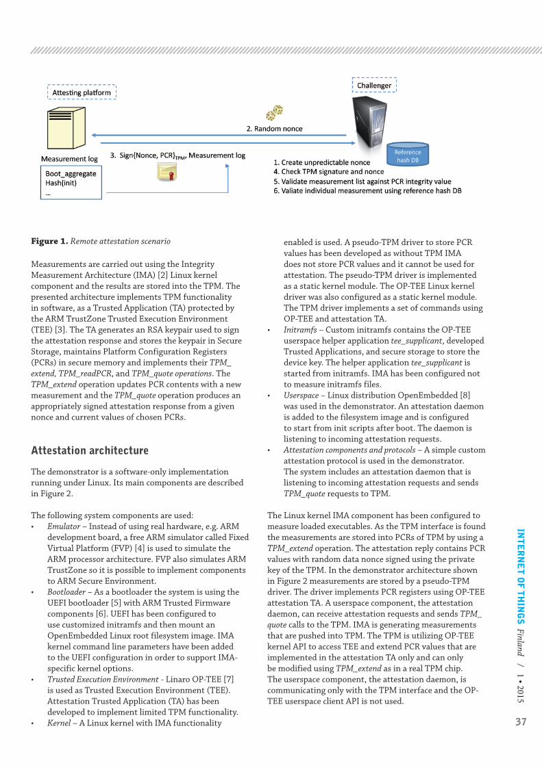
37
INT
ER
NE
T O
F T
HIN
GS
Finland / 1 • 2015
Figure 1. Remote attestation scenario
Measurements are carried out using the Integrity Measurement Architecture (IMA) [2] Linux kernel component and the results are stored into the TPM. The presented architecture implements TPM functionality in software, as a Trusted Application (TA) protected by the ARM TrustZone Trusted Execution Environment (TEE) [3]. The TA generates an RSA keypair used to sign the attestation response and stores the keypair in Secure Storage, maintains Platform Configuration Registers (PCRs) in secure memory and implements their TPM_extend, TPM_readPCR, and TPM_quote operations. The TPM_extend operation updates PCR contents with a new measurement and the TPM_quote operation produces an appropriately signed attestation response from a given nonce and current values of chosen PCRs.
Attestation architecture
The demonstrator is a software-only implementation running under Linux. Its main components are described in Figure 2. The following system components are used:• Emulator – Instead of using real hardware, e.g. ARM
development board, a free ARM simulator called Fixed Virtual Platform (FVP) [4] is used to simulate the ARM processor architecture. FVP also simulates ARM TrustZone so it is possible to implement components to ARM Secure Environment.
• Bootloader – As a bootloader the system is using the UEFI bootloader [5] with ARM Trusted Firmware components [6]. UEFI has been configured to use customized initramfs and then mount an OpenEmbedded Linux root filesystem image. IMA kernel command line parameters have been added to the UEFI configuration in order to support IMA-specific kernel options.
• Trusted Execution Environment - Linaro OP-TEE [7] is used as Trusted Execution Environment (TEE). Attestation Trusted Application (TA) has been developed to implement limited TPM functionality.
• Kernel – A Linux kernel with IMA functionality
enabled is used. A pseudo-TPM driver to store PCR values has been developed as without TPM IMA does not store PCR values and it cannot be used for attestation. The pseudo-TPM driver is implemented as a static kernel module. The OP-TEE Linux kernel driver was also configured as a static kernel module. The TPM driver implements a set of commands using OP-TEE and attestation TA.
• Initramfs – Custom initramfs contains the OP-TEE userspace helper application tee_supplicant, developed Trusted Applications, and secure storage to store the device key. The helper application tee_supplicant is started from initramfs. IMA has been configured not to measure initramfs files.
• Userspace – Linux distribution OpenEmbedded [8] was used in the demonstrator. An attestation daemon is added to the filesystem image and is configured to start from init scripts after boot. The daemon is listening to incoming attestation requests.
• Attestation components and protocols – A simple custom attestation protocol is used in the demonstrator. The system includes an attestation daemon that is listening to incoming attestation requests and sends TPM_quote requests to TPM.
The Linux kernel IMA component has been configured to measure loaded executables. As the TPM interface is found the measurements are stored into PCRs of TPM by using a TPM_extend operation. The attestation reply contains PCR values with random data nonce signed using the private key of the TPM. In the demonstrator architecture shown in Figure 2 measurements are stored by a pseudo-TPM driver. The driver implements PCR registers using OP-TEE attestation TA. A userspace component, the attestation daemon, can receive attestation requests and sends TPM_quote calls to the TPM. IMA is generating measurements that are pushed into TPM. The TPM is utilizing OP-TEE kernel API to access TEE and extend PCR values that are implemented in the attestation TA only and can only be modified using TPM_extend as in a real TPM chip. The userspace component, the attestation daemon, is communicating only with the TPM interface and the OP-TEE userspace client API is not used.
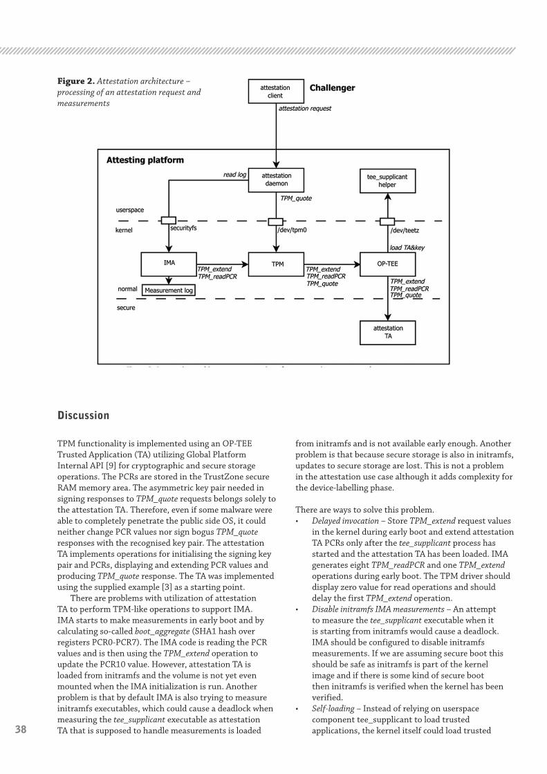
38
REMOTE ATTESTATION UTILIZING TRUSTED EXECUTION ENVIRONMENT
Discussion
TPM functionality is implemented using an OP-TEE Trusted Application (TA) utilizing Global Platform Internal API [9] for cryptographic and secure storage operations. The PCRs are stored in the TrustZone secure RAM memory area. The asymmetric key pair needed in signing responses to TPM_quote requests belongs solely to the attestation TA. Therefore, even if some malware were able to completely penetrate the public side OS, it could neither change PCR values nor sign bogus TPM_quote responses with the recognised key pair. The attestation TA implements operations for initialising the signing key pair and PCRs, displaying and extending PCR values and producing TPM_quote response. The TA was implemented using the supplied example [3] as a starting point.
There are problems with utilization of attestation TA to perform TPM-like operations to support IMA. IMA starts to make measurements in early boot and by calculating so-called boot_aggregate (SHA1 hash over registers PCR0-PCR7). The IMA code is reading the PCR values and is then using the TPM_extend operation to update the PCR10 value. However, attestation TA is loaded from initramfs and the volume is not yet even mounted when the IMA initialization is run. Another problem is that by default IMA is also trying to measure initramfs executables, which could cause a deadlock when measuring the tee_supplicant executable as attestation TA that is supposed to handle measurements is loaded
from initramfs and is not available early enough. Another problem is that because secure storage is also in initramfs, updates to secure storage are lost. This is not a problem in the attestation use case although it adds complexity for the device-labelling phase.
There are ways to solve this problem.• Delayed invocation – Store TPM_extend request values
in the kernel during early boot and extend attestation TA PCRs only after the tee_supplicant process has started and the attestation TA has been loaded. IMA generates eight TPM_readPCR and one TPM_extend operations during early boot. The TPM driver should display zero value for read operations and should delay the first TPM_extend operation.
• Disable initramfs IMA measurements – An attempt to measure the tee_supplicant executable when it is starting from initramfs would cause a deadlock. IMA should be configured to disable initramfs measurements. If we are assuming secure boot this should be safe as initramfs is part of the kernel image and if there is some kind of secure boot then initramfs is verified when the kernel has been verified.
• Self-loading – Instead of relying on userspace component tee_supplicant to load trusted applications, the kernel itself could load trusted
Figure 2. Attestation architecture – processing of an attestation request and measurements
39
INT
ER
NE
T O
F T
HIN
GS
Finland / 1 • 2015REMOTE ATTESTATION UTILIZING TRUSTED EXECUTION ENVIRONMENT
Markku Kylänpää and Aarne RantalaVTT Technical Research Centre of Finland
Espoo, Finland
applications. The loading should happen before the first measurement is done but after the file system has been mounted. There could be special partition for TAs or alternatively the TA binary could be embedded into the kernel image.
• Secure storage area – Currently the secure storage area is part of initramfs. There should be a separate non-rootfs file system to store secure storage to prevent loss of updates and to ease the labelling phase.
• Bootloader loading – TrustZone can be initialized also in the bootloader phase and the attestation TA could also be loaded by bootloader. This may actually be needed to fully support trusted/secure boot as all components have to be verified.
The current implementation is using the delayed invocation approach and all IMA measurements for initramfs have been disabled.
Conclusions and future work
An overview of the building blocks to develop an ARM TrustZone-aware remote attestation system is given and demonstration-implementation and implementation-related challenges are being discussed. Attestation TA to implement TPM-like functionality to support the attestation use case has been developed. Attestation TA is called from kernel-based software TPM implementation that is used by kernel IMA component. The main challenges have been synchronizing initialization of components in early boot. The use of a processor simulator instead of an ARM-based development board is a cost effective way to develop low-level software. However, performance evaluation cannot be done.
Future work could consist of updating the demo to utilize an ARM TrustZone-aware open-source qemu emulator instead of using an FVP emulator. Qemu provides better system emulation allowing the simulated system to also use graphical user interfaces. Another future work item is to move TEE initialization and TA loading to the bootloader phase and to use separate partition as a secure storage area. Instead of Linux userspace Android userspace could also be used and measurement mechanisms should be extended to Java virtual machines.
References
[1] ”Trusted Platform Module (TPM) Specifications,” Trusted Computing Group, [Online]. Available: http://www.trustedcomputinggroup.org/resources/tpm_main_specification.
[2] ”Integrity Measurement Architecture (IMA),” [Online]. Available: http://sourceforge.net/p/linux-ima/wiki/Home/.
[3] J. Bech, ”LCU14-103: How to create and run Trusted Applications on OP-TEE,” Linaro, September 2014. [Online]. Available: http://www.slideshare.net/linaroorg/lcu14103-how-to-create-and-run-trusted-applications-on-optee.
[4] ARM, ”ARM®v8 Foundation Model User Guide, Version: 1.0,” 2013. [Online]. Available: http://infocenter.arm.com/help/index.jsp?topic=/com.arm.doc.dui0677b/index.html.
[5] ”Unified Extensible Firmware Interface Forum,” [Online]. Available: http://www.uefi.org.
[6] ”ARM Trusted Firmware,” [Online]. Available: https://github.com/ARM-software/arm-trusted-firmware.
[7] Linaro, “OP-TEE,” Linaro, [Online]. Available: https://wiki.linaro.org/WorkingGroups/Security/OP-TEE.
[8] OpenEmbedded, “OpenEmbedded home page,” [Online]. Available: http://www.openembedded.org/wiki/Main_Page.
[9] Global Platform, ”Global Platform Specifications,” [Online]. Available: http://www.globalplatform.org/specificationsdevice.asp.
Attestation TA to implement TPM-like functionality to support the attestation use case has been developed.

40
Juhani Heinilä, Timo Niemirepo, Markus Sihvonen, Sari Ruuskanen, Vesa Jordan
UI DESIGN PROCESS OF THE ASSISTED LIVING SERVICE SYSTEM FOR SENIOR CITIZENS
A widely accepted fact is that a pleasant and intuitive user interface (UI) is extremely important for users adopting new computer systems or products. A wide variety of methods and practices for designing user interfaces of high usability and acceptability have been under research at least since Jakob Nielsen wrote his book, Usability Engineering in 1993 [1]. His message was to put more emphasis on UI design and usability of UIs due to the fact that a remarkable portion of software development is usually related to UIs. A common denominator of UI design-related research efforts has been that they underline comprehensive user studies, which aim to specify users’ needs, the context of use and the characteristics of the intended users. Validations with users of whether the design solutions and system prototypes in question meet the requirements and work as expected, are extremely important, as well.
The UI design of the Assisted Living service system for senior citizens is described in this article. In the case of creating IoT-based services and products for securing assisted living for senior citizens, additional challenges during the design process are faced. Clearly the users above the age of 80 or even 85 did not grow up using computers. Hence their lack of familiarity with using technologies, which are well known and understood by younger generations, often requires more teaching and practice. The elderly target group is not a homogeneous group of people but the diversities of the abilities and experience levels of the aged users are remarkable. Higher age often brings limitations into everyday life, and many senior citizens suffer from age-related disabilities (e.g., memory disorders, impaired vision, monochromatic sight, impaired motor skills and other sensory disabilities) which may have an impact on their performance with computerized systems. - The Assisted Living service system behind the UI has been described earlier in this publication series [2].
The Assisted Living service system pilot evaluations pointed out that the system would increase the quality of everyday life for senior citizens, e.g., by increasing their feeling of security, adding social contacts and preventing feelings of loneliness. The usability evaluation results were on a satisfactory/good level.
According to healthcare personnel working with older adults in the rehabilitation sector and participating in the pilot tests, service systems like the Assisted Living system will be a break-through technology in the near future. Such systems will be a necessity in current society due to the increasing amount of senior citizens and growing expenses associated with caring for elderly people. The introduction of new technologies will also have a changing impact on current treatment processes for the elderly.
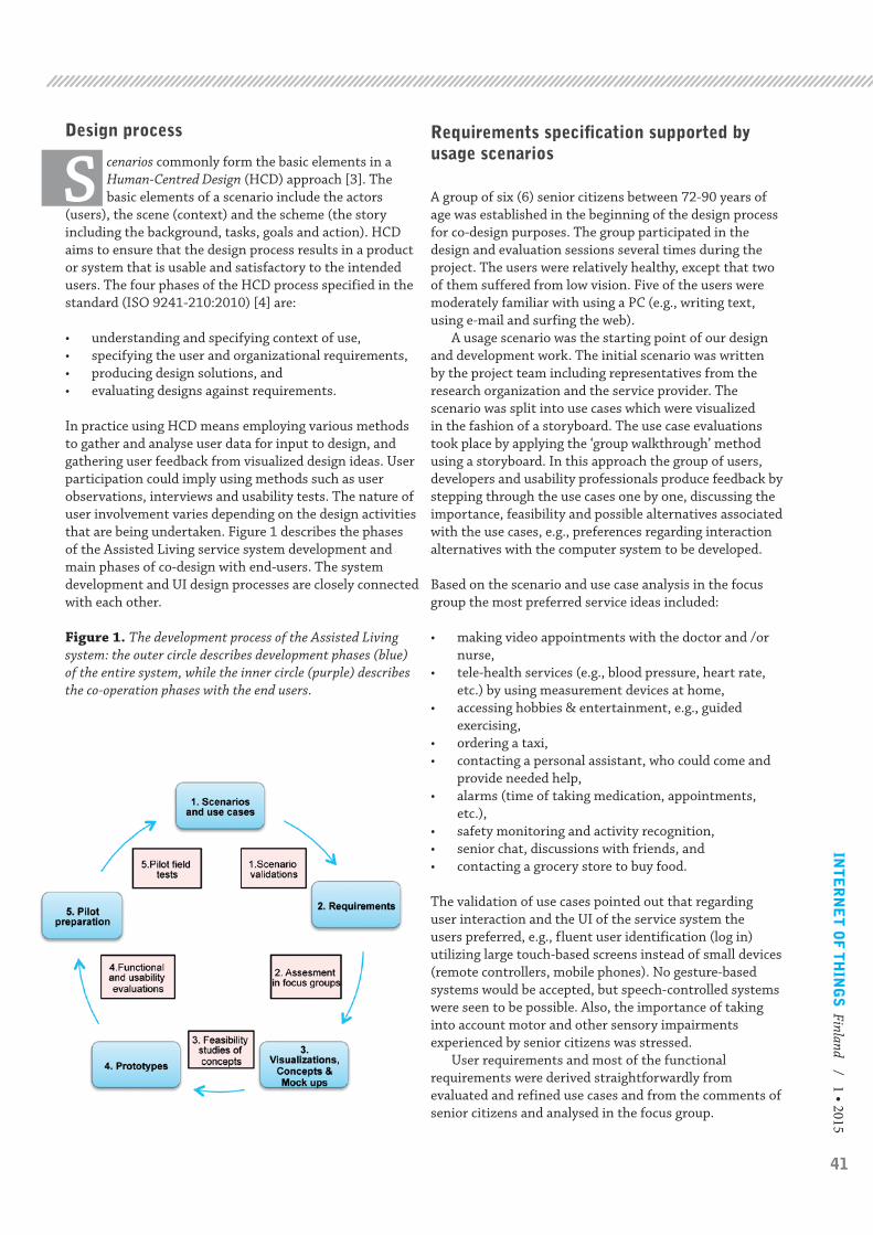
41
INT
ER
NE
T O
F T
HIN
GS
Finland / 1 • 2015
Design process
S cenarios commonly form the basic elements in a Human-Centred Design (HCD) approach [3]. The basic elements of a scenario include the actors
(users), the scene (context) and the scheme (the story including the background, tasks, goals and action). HCD aims to ensure that the design process results in a product or system that is usable and satisfactory to the intended users. The four phases of the HCD process specified in the standard (ISO 9241-210:2010) [4] are:
• understanding and specifying context of use,• specifying the user and organizational requirements,• producing design solutions, and• evaluating designs against requirements.
In practice using HCD means employing various methods to gather and analyse user data for input to design, and gathering user feedback from visualized design ideas. User participation could imply using methods such as user observations, interviews and usability tests. The nature of user involvement varies depending on the design activities that are being undertaken. Figure 1 describes the phases of the Assisted Living service system development and main phases of co-design with end-users. The system development and UI design processes are closely connected with each other.
Figure 1. The development process of the Assisted Living system: the outer circle describes development phases (blue) of the entire system, while the inner circle (purple) describes the co-operation phases with the end users.
Requirements specification supported by usage scenarios
A group of six (6) senior citizens between 72-90 years of age was established in the beginning of the design process for co-design purposes. The group participated in the design and evaluation sessions several times during the project. The users were relatively healthy, except that two of them suffered from low vision. Five of the users were moderately familiar with using a PC (e.g., writing text, using e-mail and surfing the web).
A usage scenario was the starting point of our design and development work. The initial scenario was written by the project team including representatives from the research organization and the service provider. The scenario was split into use cases which were visualized in the fashion of a storyboard. The use case evaluations took place by applying the ‘group walkthrough’ method using a storyboard. In this approach the group of users, developers and usability professionals produce feedback by stepping through the use cases one by one, discussing the importance, feasibility and possible alternatives associated with the use cases, e.g., preferences regarding interaction alternatives with the computer system to be developed.
Based on the scenario and use case analysis in the focus group the most preferred service ideas included:
• making video appointments with the doctor and /or nurse,
• tele-health services (e.g., blood pressure, heart rate, etc.) by using measurement devices at home,
• accessing hobbies & entertainment, e.g., guided exercising,
• ordering a taxi,• contacting a personal assistant, who could come and
provide needed help,• alarms (time of taking medication, appointments,
etc.),• safety monitoring and activity recognition,• senior chat, discussions with friends, and• contacting a grocery store to buy food.
The validation of use cases pointed out that regarding user interaction and the UI of the service system the users preferred, e.g., fluent user identification (log in) utilizing large touch-based screens instead of small devices (remote controllers, mobile phones). No gesture-based systems would be accepted, but speech-controlled systems were seen to be possible. Also, the importance of taking into account motor and other sensory impairments experienced by senior citizens was stressed.
User requirements and most of the functional requirements were derived straightforwardly from evaluated and refined use cases and from the comments of senior citizens and analysed in the focus group.

42
Creation and validation of UI concepts and mock-ups
After requirements were specified, first visualizations regarding the system UI were prepared. The first design solutions (mock-ups) were created with a design tool called the Balsamic Mockup (v. 2.1.15) and the Adobe AIR Player system. The toolkit facilitated a quick creation of simple sketches of the UI (Figure 2). The validation of UI mock-ups took place in the focus group so that everyone’s opinions were shared. The goal was to give the users an idea about the planned UIs and to receive their feedback regarding the feasibility of the UI for implementation into the design and development phases.
Figure 2. An example of a design solution prepared with the Balsamic Mockup toolkit.
The feasibility studies of concepts and mock-ups pointed out that UIs using dialogues requiring reading and writing are very challenging for senior citizens for many reasons. The font size should be large and clear. In addition one has to keep in mind the fact that many older adults do not necessarily have extensive prior experience with computers (e.g., at a previous job). Many of them have learned how to use a PC after they retired. Hence the computer skills of older adults may be limited or be on different levels. At the same time health (e.g., senses) and motor abilities may vary significantly within an inhomogeneous group of senior citizens.
Visualizations, concepts and mock-ups proved to be useful instruments in creation and validation of ideas. Older users may have difficulties in understanding the potential and possibilities of new technology without a tangible mock-up because it is unfamiliar to them. Also, they may feel that it is challenging to participate in co-creation activities as full members of a design group with researchers and technology developers if they feel less
familiar with technology and methods used in the design actions.
Usability of the prototypes
The prototype system consisted of two types of services, namely general and device dependent services:
• General services are services which necessitate no additional technical devices in the senior citizen’s home, except a PC.
• Device dependent services necessitate special input devices in the senior citizen’s home, e.g., a certain type of blood pressure measurement device, door sensors or a wrist-worn alarm device.
According to the international standard ISO 9241-11 Guidance on usability (1998, revised in 2008) [5], the definition of usability is defined as “the extent to which a product can be used by specified users to achieve specified goals with effectiveness, efficiency and satisfaction in a specified context of use”. Usability is defined through three attributes: effectiveness, efficiency and satisfaction which are further defined in the standard as follows:
• Effectiveness: the accuracy and completeness with which users achieve specified goals,
• Efficiency: the resources expended in relation to the accuracy and completeness with which users achieve goals, and
• Satisfaction: freedom from discomfort, and a positive attitude toward the use of the product.
The ISO 9241-11 definition of usability means that usability is not an absolute property of products but a relative property, which depends on who the users of the product are. In other words, a product might be usable for some users but difficult for others to use. This fact became strikingly clear when usability evaluations of the service system prototypes were carried out with senior citizens.
During our laboratory usability testing procedure one or two users at a time carried out given tasks under observation in laboratory conditions. The users performed a set of real tasks using the system (e.g., make an appointment with the doctor). They were asked to think aloud during the tests so that the observers could find out what the users were trying to do and why they made certain decisions. This method generated a lot of qualitative information that could be integrated into the design and development procedures. The data was gathered by making observations, by filling in forms and questionnaires and by user interviews. This way one could study how the users were able to use the system and what features they liked or disliked.
The architectural picture of the Assisted Living service system is presented in Figure 3.
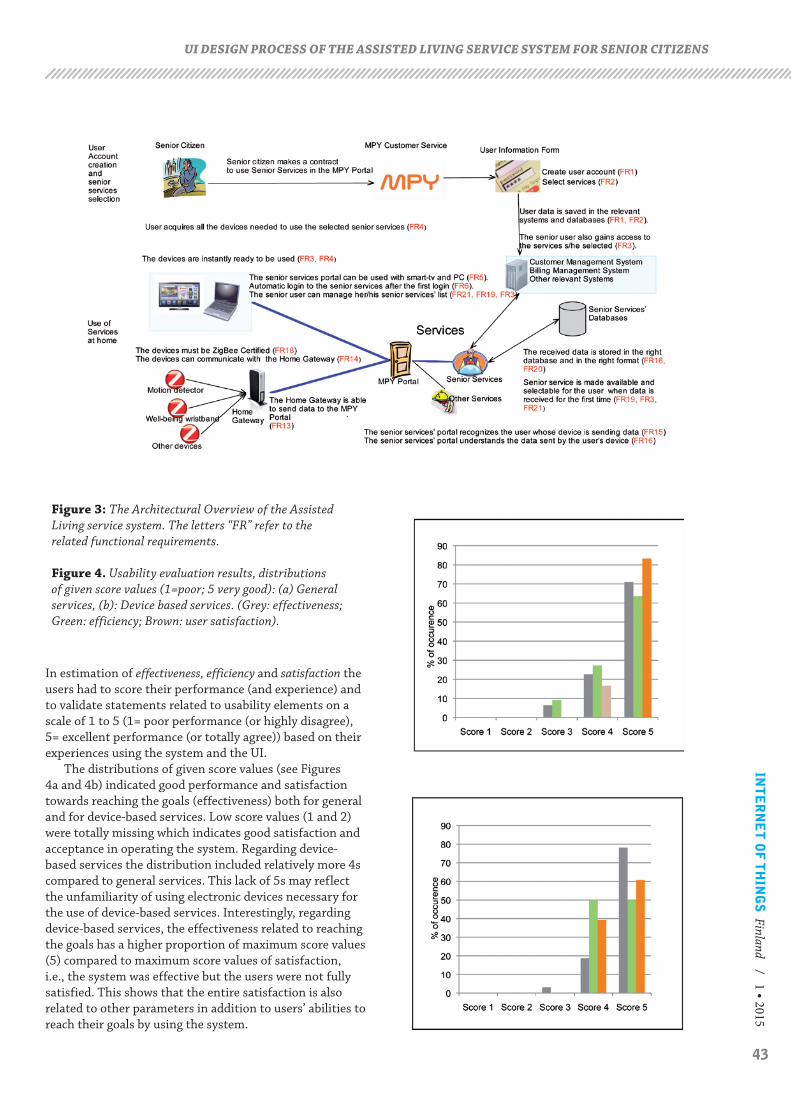
43
INT
ER
NE
T O
F T
HIN
GS
Finland / 1 • 2015
In estimation of effectiveness, efficiency and satisfaction the users had to score their performance (and experience) and to validate statements related to usability elements on a scale of 1 to 5 (1= poor performance (or highly disagree), 5= excellent performance (or totally agree)) based on their experiences using the system and the UI.
The distributions of given score values (see Figures 4a and 4b) indicated good performance and satisfaction towards reaching the goals (effectiveness) both for general and for device-based services. Low score values (1 and 2) were totally missing which indicates good satisfaction and acceptance in operating the system. Regarding device-based services the distribution included relatively more 4s compared to general services. This lack of 5s may reflect the unfamiliarity of using electronic devices necessary for the use of device-based services. Interestingly, regarding device-based services, the effectiveness related to reaching the goals has a higher proportion of maximum score values (5) compared to maximum score values of satisfaction, i.e., the system was effective but the users were not fully satisfied. This shows that the entire satisfaction is also related to other parameters in addition to users’ abilities to reach their goals by using the system.
UI DESIGN PROCESS OF THE ASSISTED LIVING SERVICE SYSTEM FOR SENIOR CITIZENS
Figure 3: The Architectural Overview of the Assisted Living service system. The letters “FR” refer to the related functional requirements.
Figure 4. Usability evaluation results, distributions of given score values (1=poor; 5 very good): (a) General services, (b): Device based services. (Grey: effectiveness; Green: efficiency; Brown: user satisfaction).
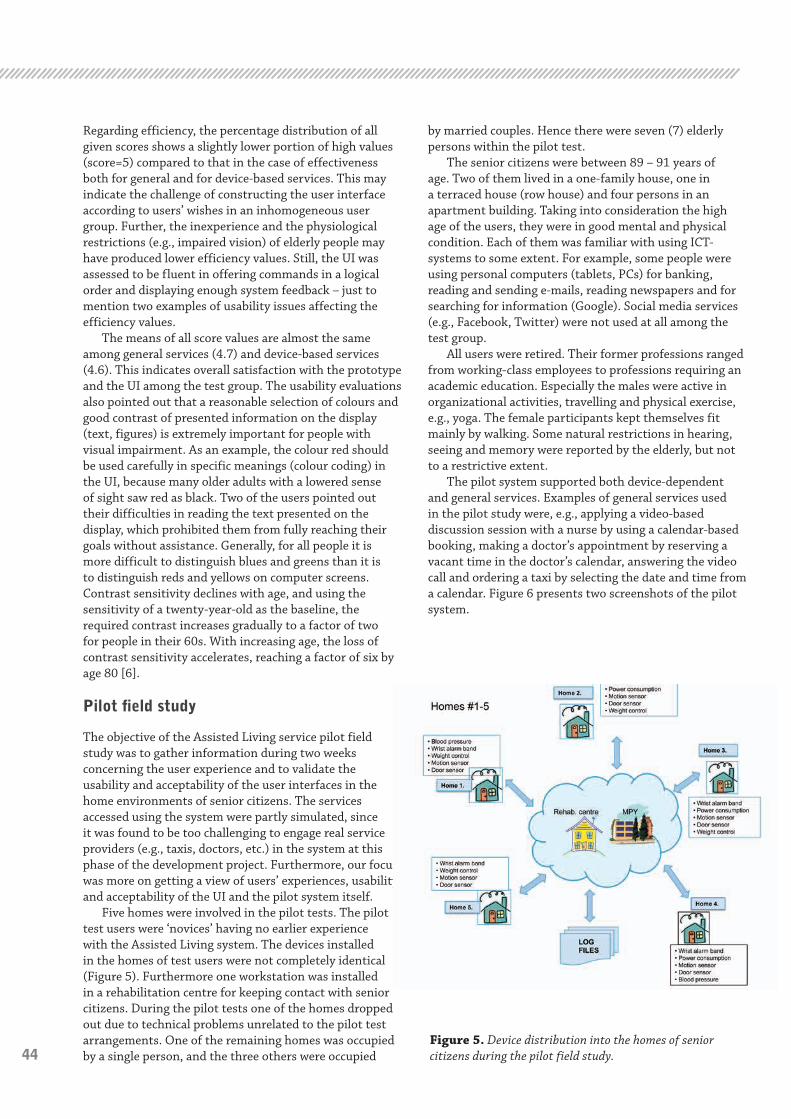
44
Regarding efficiency, the percentage distribution of all given scores shows a slightly lower portion of high values (score=5) compared to that in the case of effectiveness both for general and for device-based services. This may indicate the challenge of constructing the user interface according to users’ wishes in an inhomogeneous user group. Further, the inexperience and the physiological restrictions (e.g., impaired vision) of elderly people may have produced lower efficiency values. Still, the UI was assessed to be fluent in offering commands in a logical order and displaying enough system feedback – just to mention two examples of usability issues affecting the efficiency values.
The means of all score values are almost the same among general services (4.7) and device-based services (4.6). This indicates overall satisfaction with the prototype and the UI among the test group. The usability evaluations also pointed out that a reasonable selection of colours and good contrast of presented information on the display (text, figures) is extremely important for people with visual impairment. As an example, the colour red should be used carefully in specific meanings (colour coding) in the UI, because many older adults with a lowered sense of sight saw red as black. Two of the users pointed out their difficulties in reading the text presented on the display, which prohibited them from fully reaching their goals without assistance. Generally, for all people it is more difficult to distinguish blues and greens than it is to distinguish reds and yellows on computer screens. Contrast sensitivity declines with age, and using the sensitivity of a twenty-year-old as the baseline, the required contrast increases gradually to a factor of two for people in their 60s. With increasing age, the loss of contrast sensitivity accelerates, reaching a factor of six by age 80 [6].
Pilot field study
The objective of the Assisted Living service pilot field study was to gather information during two weeks concerning the user experience and to validate the usability and acceptability of the user interfaces in the home environments of senior citizens. The services accessed using the system were partly simulated, since it was found to be too challenging to engage real service providers (e.g., taxis, doctors, etc.) in the system at this phase of the development project. Furthermore, our focus was more on getting a view of users’ experiences, usability and acceptability of the UI and the pilot system itself.
Five homes were involved in the pilot tests. The pilot test users were ‘novices’ having no earlier experience with the Assisted Living system. The devices installed in the homes of test users were not completely identical (Figure 5). Furthermore one workstation was installed in a rehabilitation centre for keeping contact with senior citizens. During the pilot tests one of the homes dropped out due to technical problems unrelated to the pilot test arrangements. One of the remaining homes was occupied by a single person, and the three others were occupied
by married couples. Hence there were seven (7) elderly persons within the pilot test.
The senior citizens were between 89 – 91 years of age. Two of them lived in a one-family house, one in a terraced house (row house) and four persons in an apartment building. Taking into consideration the high age of the users, they were in good mental and physical condition. Each of them was familiar with using ICT-systems to some extent. For example, some people were using personal computers (tablets, PCs) for banking, reading and sending e-mails, reading newspapers and for searching for information (Google). Social media services (e.g., Facebook, Twitter) were not used at all among the test group.
All users were retired. Their former professions ranged from working-class employees to professions requiring an academic education. Especially the males were active in organizational activities, travelling and physical exercise, e.g., yoga. The female participants kept themselves fit mainly by walking. Some natural restrictions in hearing, seeing and memory were reported by the elderly, but not to a restrictive extent.
The pilot system supported both device-dependent and general services. Examples of general services used in the pilot study were, e.g., applying a video-based discussion session with a nurse by using a calendar-based booking, making a doctor’s appointment by reserving a vacant time in the doctor’s calendar, answering the video call and ordering a taxi by selecting the date and time from a calendar. Figure 6 presents two screenshots of the pilot system.
Figure 5. Device distribution into the homes of senior citizens during the pilot field study.

45
INT
ER
NE
T O
F T
HIN
GS
Finland / 1 • 2015
The device-dependent services used in the pilot evaluation were based on devices utilizing ZigBee or Bluetooth technologies, e.g., a wrist alarm band, motion detector, electronic weighing device, blood pressure measurement device, contact sensors (e.g., indicating if a door is opened or closed) and a power socket metering device.
Log files were established to store the data related to UI-actions (number, date, time, etc.) evoked by users (e.g., opening different service UIs). The log files together consisted of thousands of data lines. The high amount of user interactions showed that users were quite motivated and interested in trying the system. A separate UI used by nurses allowed distant monitoring of the measured health and sensor data of the senior citizens. Hence, e.g., door sensor data or power socket data with a time stamp could reveal normal / abnormal situations, and the nurses were able to verify whether everything was going well in the test homes. The door and movement services generated most of the device-based events into the log file followed by, in order, weight control, wrist alarm and blood pressure service usages. Entertainment, chatting, and appointment requests with a nurse, respectively, were the most often used general services among senior citizens. The nurses checked the value histories measured by senior citizens 51 times (e.g., blood pressure, door service data) during the test period.
System Usability Scale, SUS: The SU scale is commonly used for estimating usability after the respondent has had an opportunity to use the system being evaluated. The users had to score the ten statements of the SUS questionnaire with a number from 1 (‘Strongly
Agree’) to 5 (‘Strongly disagree’) [7]. An overall SUS value of 66 was calculated for the Assisted Living service system.
There are slightly different approaches regarding how to interpret the SUS values. The SUS value 66 is somewhere between “OK” and “Good” based on the analysis presented by Bangor et al. [8]. The reference for the estimation is based on numerous systems used in the SUS scale studies. The SUS value resulting from our study indicates that there are still things related to usability that need rethinking – on the other hand, the test group was minimal and the system to be tested did not offer full thinkable functionality yet. With a larger test group we could have averaged some overestimation of certain score values given by individual users.
User experience feedback: In the interviews after the testing period, senior citizens expressed that this kind of real system would increase their quality of life through enhancing their feelings of safety, ease of making social contacts and avoiding the experience of loneliness. The content of the entertainment service was lauded by all, and two of the users stated that the fitness exercising videos should be longer than two to ten minutes.
Some of the users brought up that the system has too many properties. At least some of the users seemed to have difficulty remembering how each service should be used and why such functionalities are available.
In the feedback sessions with the nurses a few comments came out regarding the system and user interfaces. For example, a healthcare provider should be able to see a broader overview of their schedule when they log into the system. It was recommended that at least one working week should be available at one glance, and it should include everything: accepted appointments, requested phone and video calls, vacant appointment times, etc. Additionally, the nurses stated that for senior citizens over 85 years old, the current user interface may include slightly too many things and choices for the user at one time.
Automatic alarms coming to a nurse’s terminal could be used if, e.g., a customer’s blood pressure values exceed predefined values frequently, or in case a senior citizen has not been moving in his/her house (door& movement sensor, using certain electrical outlets, etc.).
Discussion and conclusions
We have used a co-design approach in the design process of the Assisted Living service system for senior citizens. The system supports independent living of senior citizens in their homes. The co-design approach enabled the users, researchers and other stakeholders to co-operate creatively in creating and exploring the design ideas and validating design concepts and mock-ups. The method made possible for different stakeholders to give their opinions on the same issues effectively related to the UIs and design solutions. The process led to implementation of a pilot system, which was evaluated in field tests with senior citizens and nurses.
Figure 6. Two screenshots from the Assisted Living service system included in the pilot field study.
UI DESIGN PROCESS OF THE ASSISTED LIVING SERVICE SYSTEM FOR SENIOR CITIZENS

46
The pilot evaluation results with senior citizens pointed out that there are still challenges and opportunities for improvement of usability and the user experience. Compared to earlier usability evaluations with system prototypes in controlled circumstances, the pilot field test gave slightly lower usability estimates. Nevertheless, the senior citizens considered that a system like this would increase their quality of life, e.g., by increasing their feeling of security, adding social contacts and preventing feelings of loneliness. The services available in the system seemed to be well chosen, and the users could not name any missing services. The great amount of actions saved into log files indicated the users’ interest in the service system.
A great number of the problems encountered were related to senior citizens’ habit of turning off the power to the workstation and other devices. In spite of the instructions given to the users stating that there is no need to turn the power off to the system, this happened several times at some test sites. This caused additional problems in pairing the Bluetooth devices and ZigBee sensors with the workstation. Unnecessarily turning the power off to devices should somehow be prohibited.
According to the personnel working in the rehabilitation sector for elderly people, a system like the one used in the pilot will be a breaking-through technology in the near future. According to their comments, such systems will be a necessity in society due to the increasing amount of elderly people and growing expenses associated with taking care of the elderly. Introduction of new technologies will also have a changing impact on current treatment processes. A system like the one tested has great potential to lighten the workload of healthcare professionals and assist them in caring for their elderly customers to a greater extent.
References
[1] Nielsen, J. (1993). Usability Engineering. San Diego, Academic Press, Inc.
[2] Sihvonen, M., Jordan, V., Ruuskanen, S., Niemirepo, T., Heinilä, J. “Products for safe and secure assisted living”. Internet of Things – Finland, 1 / 2014, pp. 22-24).
[3] Heinilä, J. (ed.); Strömberg, H.; Leikas, J.; Ikonen, V.; Iivari, N.; Jokela, T., Aikio, K-P.; Jounila, I.; Hoonhout, J.; Leurs, N. Nomadic media: User-Centred Design - Guidelines for Methods and Tools. (2005), 70 p. (http://www.vtt.fi/inf/julkaisut/muut/2005/UCD_Guidelines.pdf)
[4] ISO 9241-210:2010. Human-centred Ergonomics of human-system interaction -- Part 210: Human-centred design for interactive systems.
[5] ISO 9241-11 (1998): Ergonomic requirements for office work with visual display terminals (VDTs) -- Part 11: Guidance on usability.
[6] Marc Green (2013): Visual Forensics of Older Drivers. (http://www.visualexpert.com/Resources/olderdrivers.html)
[7] Brooke, John: SUS - A quick and dirty usability scale. (http://www.usabilitynet.org/trump/documents/Suschapt.doc)
[8] Bangor, A., Kortum, P. and Miller, J. (2009): Determining what individual SUS scores mean. Adding an adjective rating scale. Journal of Usability Studies, vol 4, Issue 3, pp.114-123, 2009. (http://uxpajournal.org/determining-what-individual-sus-scores-mean-adding-an-adjective-rating-scale/
Juhani HeiniläVTT, Finland
Timo NiemirepoVTT, Finland
Markus SihvonenMPY, Finland
Sari Ruuskanen,MPY, Finland
Vesa JordanMPY, Finland
UI DESIGN PROCESS OF THE ASSISTED LIVING SERVICE SYSTEM FOR SENIOR CITIZENS
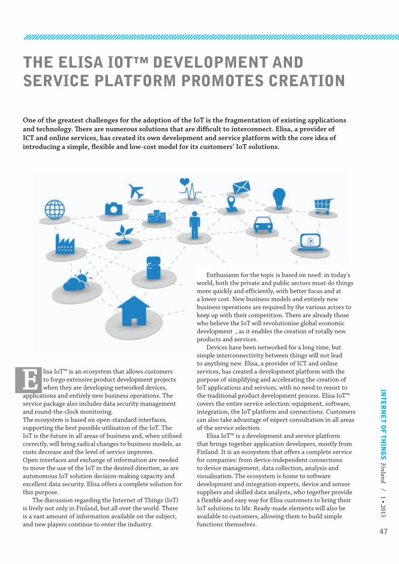
47
INT
ER
NE
T O
F T
HIN
GS
Finland / 1 • 2015
THE ELISA IOT™ DEVELOPMENT AND SERVICE PLATFORM PROMOTES CREATION
One of the greatest challenges for the adoption of the IoT is the fragmentation of existing applications and technology. There are numerous solutions that are difficult to interconnect. Elisa, a provider of ICT and online services, has created its own development and service platform with the core idea of introducing a simple, flexible and low-cost model for its customers’ IoT solutions.
E lisa IoT™ is an ecosystem that allows customers to forgo extensive product development projects when they are developing networked devices,
applications and entirely new business operations. The service package also includes data security management and round-the-clock monitoring.The ecosystem is based on open-standard interfaces, supporting the best possible utilisation of the IoT. The IoT is the future in all areas of business and, when utilised correctly, will bring radical changes to business models, as costs decrease and the level of service improves.Open interfaces and exchange of information are needed to move the use of the IoT in the desired direction, as are autonomous IoT solution decision-making capacity and excellent data security. Elisa offers a complete solution for this purpose.
The discussion regarding the Internet of Things (IoT) is lively not only in Finland, but all over the world. There is a vast amount of information available on the subject, and new players continue to enter the industry.
Enthusiasm for the topic is based on need: in today's world, both the private and public sectors must do things more quickly and efficiently, with better focus and at a lower cost. New business models and entirely new business operations are required by the various actors to keep up with their competition. There are already those who believe the IoT will revolutionise global economic development , as it enables the creation of totally new products and services.
Devices have been networked for a long time, but simple interconnectivity between things will not lead to anything new. Elisa, a provider of ICT and online services, has created a development platform with the purpose of simplifying and accelerating the creation of IoT applications and services, with no need to resort to the traditional product development process. Elisa IoT™ covers the entire service selection: equipment, software, integration, the IoT platform and connections. Customers can also take advantage of expert consultation in all areas of the service selection.
Elisa IoT™ is a development and service platform that brings together application developers, mostly from Finland. It is an ecosystem that offers a complete service for companies: from device-independent connections to device management, data collection, analysis and visualisation. The ecosystem is home to software development and integration experts, device and sensor suppliers and skilled data analysts, who together provide a flexible and easy way for Elisa customers to bring their IoT solutions to life. Ready-made elements will also be available to customers, allowing them to build simple functions themselves.

48
real-time, remotely measured and analysed patient information. With health-related information available, patient care can be optimised and mistakes in care reduced.
Certified data security is integral to the solution
As more devices are connected to the public network, there is no question that the number of potential security risks will increase. Having open interfaces and a horizontal operating model present demanding data security requirements, and this must be taken into account in the connections, management applications and equipment. With centralised and role-based data network management, Elisa can ensure that no external parties can access the devices or information on the network. Location is an additional data security feature: Elisa hosts its cloud services in Finland.
Customers will have a single unified view of the network equipment and reporting. Service provider access can be restricted to the devices that the service provider is responsible for. The system also allows different user levels to be defined, e.g. for read and write permissions.
Elisa's cyber-services are built to stop threats before they impact any of our customers’ business-critical services.
One of the most notable benefits of the IoT is the ability to use the information from networked devices in the real-time management of business operations and product development. Elisa recognises that proprietary models and environments are holding back the creation and introduction of new services – the IoT will enable closer connections with customers, whether they are in manufacturing, health care, logistics or consumer services. This is why the Elisa ecosystem is based on a fully open service and development platform.
References
[1] http://www.networkworld.com/article/2854675/internet-of-things/the-internet-of-things-may-bring-a-new-economic-boon.html
Open and horizontal operations make the IoT agile
Elisa is well aware that device data transfer alone is not enough to collect data with actual value. The Elisa ecosystem supports industry-specific background system integration (e.g. Salesforce, SAP). The ecosystem has over 30 application development members. Elisa aims to provide its customers with a comprehensive overall picture of the various possibilities.
Elisa is focused on maintaining the service and development platform. Through its ecosystem, Elisa will act as a provider, who will build tools for its customers to further develop their applications as necessary. Elisa IoT™ operates horizontally via open-standard interfaces. The platform allows the creation of basic applications in minutes, and various background systems can be integrated quickly. Different ideas and models can be conveniently tested, and conclusions regarding the viability of the applications can be reached promptly.
Open standards and horizontal operations mean that the data collected from the various sources in Elisa IoT™ can be easily transformed into information relevant for the business. With this up-to-date information, Elisa customers will have a strong competitive advantage: by analysing the data, they can make projections for their business and optimise their production and process chains.
Elisa firmly believes that every single industry will benefit from the opportunities presented by the IoT. The greatest opportunities for utilising the IoT are seen to be in the manufacturing industry and the health services sector.
Optimal use of the IoT brings various benefits
New services: the IoT will increase the number of new services, as systems will begin to communicate and are allowed to interconnect. There may even be links between industries.
New business models: the ability to monitor and analyse data through IoT solutions may result in the development of completely new business models for service businesses. For example, car rental businesses or insurance companies could award customers discounts based on their driving habits, once vehicle use and drivers can be monitored and analysed.
Cost savings: once devices are able to communicate with one another, this will present a great cost-saving opportunity for businesses. Real-time equipment monitoring will allow remote maintenance and service operations. The causes and consequences of issues can be analysed more rapidly. Devices can also be taught to operate independently. Automatic device monitoring also allows user errors to be identified, so practices can be implemented to reduce them and hence reduce costs.
Cost savings will not be limited to manufacturing; for example, health care operations can benefit from
SUBJECT
49
INT
ER
NE
T O
F T
HIN
GS
Finland / 1 • 2014
it, and, as a consequence, promote student-centered, active learning models of instruction. Many of these views stem from the work by Dewey, who wrote that “probably the greatest and commonest mistake that we make is to forget that learning is a necessary incident of dealing with real life situations” [5]. According to Dewey, personal experience can not be substituted by even the most sophisticated learning materials. Our experiment started with a problem-based setup. In problem-based learning students are sent to solve realistic and substantial problems [8, 2]. The problem creates focus for the project, stimulates the student’s thinking, positioning the individual at the epicenter of the learning experience. According to Norman, instructors should provide only limited help in form of guidance in order to allow the students to develop domain-specific knowledge and effective problem-solving skills. While students engage in the problem independently, they are guided to find their own thinking strategies and ways of working which improves their self-directed learning skills [8]. Barrows [2] outlines five guidelines for teachers who want to use this approach in their tuition:
1. The teacher must provide a driving question that students seek answers to, without any predetermined outcome.
2. Learning objectives and goals need to be centered around the problem.
3. Students should approach the problem through constructive investigations.
4. They should work in an autonomous manner.5. Projects need to be realistic so that students can make
connections to authentic situations and draw from their past experiences
Introduction
T he ACM 2013 Computer Science Curricula emphasizes that the education offered to students should prepare them for the workforce
in a more holistic way than simply conveying technical facts and realities. In this context, soft skills such as teamwork, creative problem solving and sense of social responsibility are emphasized [9]. To explore these principles, we arranged creative Internet of Things (IoT) prototyping course for students of the Department of Computer Science in University of Helsinki in May 2014. The overarching goal of our educational experiment was to increase the students’ capabilities to work in diverse technological environments and therefore they were allowed to independently choose their individual projects’ hardware and software architectures independently from a selection of very heterogeneous options. Also the scope of their projects was formed independently, which led each student's solution to be different. One of our learning goals was to make students work together towards creating a holistic system to provide a solution for the initial problem. We feel that our learning experiment was especially well suited for its purpose and provided meaningful learning experiences for students with varying backgrounds and skill levels.
Background
The experiment described in this article builds on the constructivist view of learning that suggests that people actively construct knowledge rather than receive and store it (see e.g. [6, 7, 3]). Constructivists view knowledge as something that cannot be copied from what a teacher said, define it as unique to those who have constructed
Hanna Mäenpää, Sasu Tarkoma, Samu Varjonen and Arto Vihavainen
BLENDING PROBLEM- AND PROJECT-BASED LEARNING IN INTERNET OF THINGS EDUCATION: CASE EXACT GREENHOUSE
This article describes an experimental course, that blended problem- and project-based learning, where students developed Internet of Things device prototypes to improve the upkeep of an urban rooftop greenhouse. With the help of a problem-based learning approach, students were first familiarized with their new learning environment and encouraged to find issues that could be improved as a meaningful personal learning experience. A project-based learning approach was then used to develop innovative solutions while validating their relevance in collaboration with gardeners that were taking care of the greenhouse. As a result, a number of practical applications for monitoring the state of the greenhouse were developed along with new practices for its maintenance. As participants were given the freedom to choose both the topic and technologies to work with, the course provided a learning experience that was tailored to suit personal interests and competences. Having the common background story allowed students to practice teamwork skills and collaborative software engineering in the context of the emerging topic of Internet of Things.

50
The problem-based learning theory is supported by the Inductive learning theory, which is defined by Prince et al. [11] as an experience where students are given a starting point from which they gather observations that drive their further actions. As the insight individuals gain is a highly personal interpretation, their learning pathways become diversified. In project-based learning students have more freedom to choose the task that they will be working on and the domain is at least partially known beforehand [4, 12]. Authors such as Barron et al. [1] have suggested combining problem- and project-based learning in a way that students are provided with a problem that acts as the framework of the project and helps students form initial knowledge, which can be further developed in a project:
“For example, by beginning with a simulated problem, students develop a level of shared knowledge and skill that prepares them to undertake actual projects. By following the problem with a project, students are likely to develop more flexible levels of skills and understanding. [1]”
THE GREENHOUSE PROJECT
The Exact Greenhouse facility is located on the rooftop terrace of the department. It was originally set up for research on Green ICT to study the possibility of cooling computer servers with unconditioned outside air, while harvesting exhaust heat into a greenhouse during the Finnish winter time [10]. After this research was ended, we converted the facility to serve as an exciting multidisciplinary learning and research “sandbox” that focuses on research and hands-on experimentation with emerging technologies in order to discover and demonstrate the promise of the IoT.
The Exact Greenhouse -course
Thirteen participants for our intensive course were selected from 25 enrolled students. Limiting the amount of participants was done to ensure meaningful learning experiences and to facilitate studying the course structure and organization. Our criteria for student selection was that the students should be MSc students at the very end of their studies.
The week project course had a tangible and well framed narrative that was initially presented to the students in the course description. Students were set out to create solutions that would help the greenhouse maintenance team to perform their work better, while being informed about the ambient conditions of the greenhouse. Participants were taken to visit the greenhouse to observe and discuss characteristics of the structure and needs for plant care. The driving problems for each project was then outlined with the greenhouse caretaker team. Students brainstormed problems in maintaining the greenhouse and sketched solutions for solving them. After the meeting participants were set off with the hardware and their first task: to get to know the technology and to
identify components that were required for their project's implementation. This was the first milestone of the course.
The course communication in between organizers and students was arranged mainly on a course Facebook page. The majority of students also were present in an real-time Internet chat room (IRC) that had originally been created for the greenhouse maintenance team’s internal communication.
On their second meeting students met a professional gardener who provided detailed instructions related to plant care and provided feedback on the relevance of the students’ plans. The feasibility of some of the project ideas were also discussed with the course staff. During the following weeks, students built their hardware prototypes and developed related software. Voluntary weekly meetings were arranged on Mondays and the course staff provided technical help on demand.
A second milestone was set to ensure that all

51
INT
ER
NE
T O
F T
HIN
GS
Finland / 1 • 2015
projects had found means to make data yielded from their IoT devices available into a human-readable form. The students had to show that their prototypes were connected to the Internet and that data they produced was stored in a cloud service. After this milestone, students continued testing and improving their prototypes.
A course wrap-up meeting was arranged where the students demonstrated their project's deliverables. Having learned about IoT technologies and seeing the solutions of others, the students were also able to compare differences of technologies and to contemplate on how choosing an another microcontroller environment could possibly have changed their workflow. As the last milestone the students were required to document their learning experience to the course blog1.
Learning Objectives and Assessment
As is normal for problem-based learning, the learning objectives of the course were not stated at the beginning of the course. However, it was determined beforehand by the course instructors that students should learn IoT concepts, learn how their skills can be used in places where one does not typically think about it, and that the students should also be able to design and develop a small solution that meaningfully helps the greenhouse management at least in some fashion. No restrictions were made on how students approached the problem. The rough course schedule that was outlined in the previous section encouraged students to collaborate and help each other while their work proceeded.
The course was graded pass/fail. In order to pass, students had to pass the three aforementioned milestones, and to provide the source code for their project via a version control system (in our case, GitHub). The assessment approach was chosen due to the variety of different paths that students could take as well as due to the open-ended nature of the project.
Unexpected learning outcomes
For the whole duration of the course, students were participating in the greenhouse caretaker team’s online chat. The encounters encounters led to discussions on what type of knowledge would be useful for facilitating the team’s work. They also created new knowledge for the maintenance team on how their inter-person collaboration could be improved. Contrary to our expectations, we quickly observed that prototyping simple ideas using microcontrollers and connecting them to the internet was easy for the participants. As devices were built and left running for a time, we discovered that the microcontrollers used plenty of electricity consider-ing their size and functionality. Even the simplest prototype measuring the level of lighting of a room emptied its batteries in a few days. This led us to discussions on energy efficiency and the carbon footprint of the devices that we use in everyday life. The students explored various optimization strategies such as disconnecting the components from the internet for longer periods and activating components only when needed. While doing so, they also learned to
consider issues such as measurement accuracy. These topics were new to both students and the course staff. Those that were not able to attend the final get-together presented their work for a course instructor privately. These students missed a great peer-to-peer discussion while participants compared their solutions that shared a similar purpose, but were built on very different technologies. As one of the students put it:
“During the demo session, I understood how different the solutions were both from the hardware-and software-perspective. I would not have been able to compare technologies without my own project, as my knowledge was not at a level that I could have talked about it in a meaningful way.”
BLENDING PROBLEM- AND PROJECT-BASED LEARNING IN INTERNET OF THINGS EDUCATION: CASE EXACT GREENHOUSE
52
Hanna Mäenpää, Sasu Tarkoma, Samu Varjonen, and Arto Vihavainen
Department of Computer Science, University of Helsinki
CONCLUSIONS
We have described an experimental course where students develop Internet of Things applications for improving the maintenance of a greenhouse. The course was organized in two phases. First, a problem-based learning approach was used to learn about the environment, identify problems and to come up with solutions for improving them. In the second phase, the students worked on projects, where these solution ideas were made real. The outcome of this project contrasted the wide array of possibilities that blending problem- and project-based learning approaches can provide for students and teachers. Overall, the experience did not only teach students about technical aspects that were related to the Internet of Things, but also provided viewpoints on urban sustainability and Green ICT.
The experiment demonstrated to the department that the organization of such loosely defined projects with little predefined hardware and a relatively small budget can provide both a successful and valuable learning experience. Both the gardeners and the students in the course gained experiences that are likely to benefit their future, many of them praising the course as an eye-opening experience. Our scientific contribution was presented at ACM's SIG conference on Computer Science Education (SIGCSE2015), receiving generous amount feedback and new international contacts. The course was repeated in 2015 with 23 attendants and research on the new way of organizing Internet of Things continues at the Department of Computer Science at the University of Helsinki.
1 http://blogs.helsinki.fi/greenhouseproject/
References
[1] B. J. Barron, D. L. Schwartz, N. J. Vye, A. Moore, A. Petrosino, L. Zech, and J. D. Bransford. Doing with understanding: Lessons from research on problem-and project-based learning. Journal of the Learning Sciences, 7(3-4):271–311, 1998.
[2] H. S. Barrows. Problem-based learning in medicine and beyond: A brief overview. New Directions for Teaching and Learning, 1996(68):3–12, 1996.
[3] M. Ben-Ari. Constructivism in computer science education. Journal of Computers in Mathematics and Science Teaching, 20(1):45–73, 2001.
[4] P. C. Blumenfeld, E. Soloway, R. W. Marx, J. S. Krajcik, M. Guzdial, and A. Palincsar. Motivating project-based learning: Sustaining the doing, supporting the learning. Educational psychologist, 26(3-4):369–398, 1991.
[5] V. Callaghan. Buzz-Boarding; practical support for teaching computing based on the internet-of-things. 2012.
[5] J. Dewey. The School and the Society: Rev. Ed. University of Chicago Press, 1967.
[6] R. Driver and B. Bell. Students’ thinking and the learning of science: A constructivist view. School science review, 67(240):443–56, 1986.
[7] T. Greening. Emerging constructivist forces in computer science education: Shaping a new future? In Computer science education in the 21st century, pages 47–80. Springer, 2000.
[8] G. R. Norman and H. G. Schmidt. The psychological basis of problem-based learning: a review of the evidence. Academic medicine, 67(9):557–65, 1992.
[9] A.-C. J. T. F. on Computing Curricula. Computer science curricula 2013. Technical report, ACM Press and IEEE Computer Society Press, December 2013.
[10] M. Pervilä, L. Remes, and J. Kangasharju. Harvesting heat in an urban greenhouse. In ACM SIGMETRICS Performance Evaluation Review, volume 41, pages
95–97, 2013.[11] M. Prince and R. Felder. Inductive teaching and
learning methods: Definitions, comparisons, and research bases. Journal of engineering education, 95(2):123–138, 2006.
[12] J. W. Thomas. A review of research on project-based learning. 2000.
BLENDING PROBLEM- AND PROJECT-BASED LEARNING IN INTERNET OF THINGS EDUCATION: CASE EXACT GREENHOUSE

53
INT
ER
NE
T O
F T
HIN
GS
Finland / 1 • 2015
MY SMART HOME WITH THE HEAD IN THE CLOUD
I arrive home after work. As I open the front door, the home recognizes and greets me, by my name, via a message to my mobile. The home also checks if it is
dark enough already and, because it is, switches on the floor lamp in the far corner of the living room (the main light we keep on during the evening). It is enough to light my way around the entrance and removes the need for switching onany other lights temporarily. If it were not dark yet, the home would wait until it gets dark and then switch the lamp on.
I remove my coat and hang it in the wardrobe at the entrance. I forget to close the sliding door of the wardrobe. In a few minutes, the home reminds me about that (because it just does not look nice to have it open) via a "visual alarm" - repeatedly switching on and off a small table lamp. It also sends a message to my mobile. From the three options available to me: ignoring it (blinking will stop in a minute), acknowledging it from the mobile, and going on and closing the door, I choose the last option. The alarm stops, leaving the table lamp in the state it was before the alarm, off in this case.
On my mobile, I click on "Music". The home responds with a list of Spotify playlists we like. With one touch, I choose "Cozy Evening" and the music starts playing.
I realize that I have to run an errand to the supermarket. From my mobile, I ask about the current weather outside and the home answers with info about the temperature and the wind speed. I leave the house. As soon as the home realizes that I have left, while there is a light on, it sends me a question to the mobile whether I want to switch all the (connected) lights off. I respond "No", as I will be back soon.
I return. On my computer connected to the TV, I start playing a video. After a while, I go to the kitchen to make tea. The video pauses. When I walk back into the living room, the video resumes playing.
Later at night, I switch the TV off. The home notices this. It also knows that at this hour this always means we are moving upstairs to the bedroom. Therefore, after a small delay, the home switches all the living room lights off.
True story.
Ingredients
• 1 x Z-Wave gateway box (by There Corp.) with its HTTP API
• 2 x motion detectors, 1 x door contact sensor, 3 x on/off sockets with power consumption meters, 1 x temperature/humidity sensor (optional)
• 1 x Finnish Meteorological Institute (FMI) light conditions Open Data service, 1 x FMI temperature service, 1 x FMI wind speed service
• 1 x VLC video player's HTTP control interface• 1 x Spotify's open HTTP interface• 1 x VTT's DataBearings software platform• 1 x VTT's InstantSurvey Android app
Approach
The above control and automation functions add some convenience to our daily life. True, they do not save us money or similar and, thus, can hardly make one a believer in the smart home technology as such. The point here is rather about the approach. Our smart home is not restricted to the functionality of any single home automation product. Rather, a number of systems and online services, whatever we happen to have access to, are mashed together to enable whatever applications we could come up with (make no mistake, this is not an advertisement for Z-Wave in particular). No soldering, no reliance on a single commercial platform, but mashing up various APIs.
With properly configured port forwarding at the home WiFi router, the software that controls the home does not need to be located within the home network but can be in the Cloud.
“Gentlemen, I am now about to send a signal from this laptop through our local ISP, racing down fibre-optic cable at the speed of light to San Francisco, bouncing off a satellite in geosynchronous orbit to Lisbon, Portugal, where the data packets will be handed off to submerged transatlantic cables terminating in Halifax, Nova-Scotia, and transferred across the continent via microwave relays back to our ISP and the X10 receiver attached to this … … lamp!” (Big Bang Theory, season 1, episode 9).
OK, not such a long trip for data, and without such a delay as in that show back in 2008. But, yes, our home in Finland is controlled by software which runs on an Amazon virtual server somewhere in Germany.
The smart home logic that controls our home is very modular, with each of the above-mentioned functions being a separate "smart home app" that can be enabled or disabled easily. The guiding vision is a "smart home app store" where people could publish the apps they came up with for everyone else to try out (similar to what we have now with smartphones).
Artem Katasonov

54
DataBearings
Sure, the last section may have sounded familiar, thanks to IFTTT.com. Our implementation, however, uses VTT's DataBearings, which allows us to easily connect whatever systems and services we want, as well as allows any complexity of logic beyond simple if-then rules of IFTTT. DataBearings is a product of the DIGILE Internet of Things program.
DataBearings provides semantic data virtualization and semantic data abstraction functions, and we exploit both to allow the top-level code, i.e. "apps", to be as concise as possible without sacrificing any of the overall generality and flexibility.
Figure 1. Semantic data virtualization in DataBearings
Figure 1 presents a top-level overview of the data virtualization mechanism in DataBearings and more information about it can be found in [1]. This mechanism allows working with heterogeneous non-semantic data as if they were all represented according to a uniform semantic model, i.e. an ontology. In our implementation, data from Z-Wave sensors, data from FMI's services, human answers to the questions on the user interface - these all get mapped to the W3C's Semantic Sensor Network (SSN) ontology. SSN is simple and very general. Everything is modeled as observations. Every
observation has a feature of interest (e.g. a living room), an observed property of that feature (e.g. temperature in degrees Celsius), observation result (e.g. 22), observation result time, and observed by - object that generated the observation (e.g. sensor1).
SSN is really general and allows almost any home-automation-related data to be mapped to it. Yet, if the automation rules were expressed in SSN constructs directly, they would be quite long and hard to understand. One problem is that a temperature sensor does not know the temperature of what it measures. The relation between 'sensor1' and 'living room' has thus to be described separately and handled when executing a rule. Another problem is that it is 'the current temperature' that is typically of interest, not some time-stamped observations. The semantic data abstraction mechanism in DataBearings allows defining convenient-to-use classes and properties, with the system taking care of expanding them into their full forms. In our implementation, an app can simply say "if the temperature in the living room is below X". DataBearings will expand it to "if the observation with the largest time-stamp from a sensor observing a temperature property and linked to the feature of interest 'living room' has the observation result below X".
The semantic nature of DataBearings also allows apps to rely on classes rather than instances. When an app wants to "switch all lights off", technically, it needs to send an 'off' command to each relevant remotely controlled on/off socket. However, as sockets are linked to features of interest (lamps, TVs), and features of interest are linked to classes, the app can just say to switch off the instances of the Light class, letting the system find the proper list of sockets. All other apps are also defined in terms of classes. In our implementation, there are such classes as BasicLight (what to switch on when somebody comes home), AlarmLight (what to use for "visual alarm"), MonitoredDoor (what to monitor and alarm if left open). Re-assigning some functionality to a different device (sensor or socket) is thus a question of adding/removing a classification for its feature of interest.
Figure 2. DataBearings run time performance
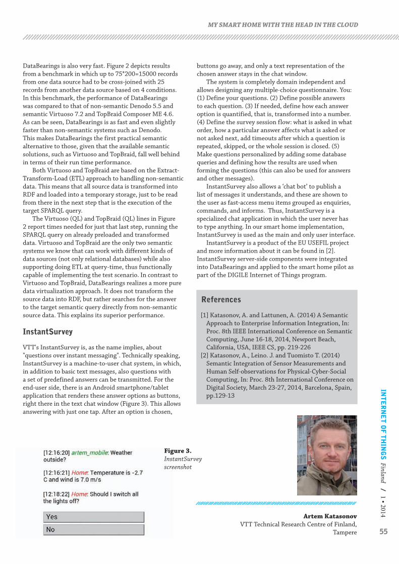
55
INT
ER
NE
T O
F T
HIN
GS
Finland / 1 • 2014
DataBearings is also very fast. Figure 2 depicts results from a benchmark in which up to 75*200=15000 records from one data source had to be cross-joined with 25 records from another data source based on 4 conditions. In this benchmark, the performance of DataBearings was compared to that of non-semantic Denodo 5.5 and semantic Virtuoso 7.2 and TopBraid Composer ME 4.6. As can be seen, DataBearings is as fast and even slightly faster than non-semantic systems such as Denodo. This makes DataBearings the first practical semantic alternative to those, given that the available semantic solutions, such as Virtuoso and TopBraid, fall well behind in terms of their run time performance.
Both Virtuoso and TopBraid are based on the Extract-Transform-Load (ETL) approach to handling non-semantic data. This means that all source data is transformed into RDF and loaded into a temporary storage, just to be read from there in the next step that is the execution of the target SPARQL query.
The Virtuoso (QL) and TopBraid (QL) lines in Figure 2 report times needed for just that last step, running the SPARQL query on already preloaded and transformed data. Virtuoso and TopBraid are the only two semantic systems we know that can work with different kinds of data sources (not only relational databases) while also supporting doing ETL at query-time, thus functionally capable of implementing the test scenario. In contrast to Virtuoso and TopBraid, DataBearings realizes a more pure data virtualization approach. It does not transform the source data into RDF, but rather searches for the answer to the target semantic query directly from non-semantic source data. This explains its superior performance.
InstantSurvey
VTT's InstantSurvey is, as the name implies, about "questions over instant messaging". Technically speaking, InstantSurvey is a machine-to-user chat system, in which, in addition to basic text messages, also questions with a set of predefined answers can be transmitted. For the end-user side, there is an Android smartphone/tablet application that renders these answer options as buttons, right there in the text chat window (Figure 3). This allows answering with just one tap. After an option is chosen,
buttons go away, and only a text representation of the chosen answer stays in the chat window.
The system is completely domain independent and allows designing any multiple-choice questionnaire. You: (1) Define your questions. (2) Define possible answers to each question. (3) If needed, define how each answer option is quantified, that is, transformed into a number. (4) Define the survey session flow: what is asked in what order, how a particular answer affects what is asked or not asked next, add timeouts after which a question is repeated, skipped, or the whole session is closed. (5)Make questions personalized by adding some database queries and defining how the results are used when forming the questions (this can also be used for answers and other messages).
InstantSurvey also allows a ‘chat bot’ to publish a list of messages it understands, and these are shown to the user as fast-access menu items grouped as enquiries, commands, and informs. Thus, InstantSurvey is a specialized chat application in which the user never has to type anything. In our smart home implementation, InstantSurvey is used as the main and only user interface.
InstantSurvey is a product of the EU USEFIL project and more information about it can be found in [2]. InstantSurvey server-side components were integrated into DataBearings and applied to the smart home pilot as part of the DIGILE Internet of Things program.
References
[1] Katasonov, A. and Lattunen, A. (2014) A Semantic Approach to Enterprise Information Integration, In: Proc. 8th IEEE International Conference on Semantic Computing, June 16-18, 2014, Newport Beach, California, USA, IEEE CS, pp. 219-226
[2] Katasonov, A., Leino. J. and Tuomisto T. (2014) Semantic Integration of Sensor Measurements and Human Self-observations for Physical-Cyber-Social Computing, In: Proc. 8th International Conference on Digital Society, March 23-27, 2014, Barcelona, Spain, pp.129-13
MY SMART HOME WITH THE HEAD IN THE CLOUD
Artem Katasonov VTT Technical Research Centre of Finland,
Tampere
Figure 3. InstantSurvey screenshot

56
Standardization in IoT and Industrial internet
T he Internet of Things (IoT) embodies a vision where the internet can stretch to the real world including everyday objects and physical items
that are in connection to the virtual world [14]. Industrial internet connects smart machines, devices and people at work, leading to better decision making through advanced analytics that result in transformational business outcomes. Industrial internet comprehends the non-consumer side of IoT and applies “internet thinking” in industrial settings [8].
Several technological challenges need to be solved before the IoT vision can become reality, such as how to achieve interoperability between connected devices. In addition, security, privacy and trust have to be guaranteed for users and to their data. Many industrial, standardization and research bodies are involved in development activities to fulfil the technological requirements for IoT. [4, 1]
Standardization provides benefits for technology, society and economy. Standards also affect sustainability as they provide ways for the management of processes and the use of technologies influencing social, environmental and economic aspects. Standards provide benefits in the following respects: interoperability, reliability, safety, business benefits, consumer choice, support of legislation and government policies. Standards play an important
role in IoT and they are vital for allowing all players equivalent use and access. IoT standardization is complex and includes different standards, such as architecture standards, communication protocol standards, application requirements standards, identification standards, information processing standards, security standards, data standards, public service platform standards, etc. Standards development will further effective development of IoT devices, applications, services and infrastructures. In today’s IoT world, global standards are more relevant than local agreements. [19, 5, 2]
Standardization work is multidimensional and there are numerous standardization bodies and organizations, both proper Standards Development Organizations (SDOs) and special standards specifications developing alliances and interest groups. Some standards define entire systems or parts of systems, while some organizations develop specific pieces of technologies, such as specific communication protocols [6]. It is important to have common standards to build a successful IoT ecosystem. Diverse and fragmented standards and interfaces between systems complicate the innovation capability of service providers and application developers. Many evolving applications use their own standards and major standards are under development. By creating commonly accepted standards, developers and users can implement IoT applications and services which can be deployed on a large scale. Standardization can speed up the spread of IoT innovations and technology, and in the
STANDARDS IN IOT, INDUSTRIAL INTERNET AND CONDITION-BASED MAINTENANCE
Abstract
The purpose of this paper is to study standardization in IoT and Industrial internet. The study seeks to introduce and analyse relevant standards, standardization organizations and the current state of standardization related to IoT and Industrial internet. The perspective of this study is on condition-based maintenance; however other important aspects, such as networking and wireless communications, are included as well.
Industrial internet will have a great impact on business, industry, societies and the ways we work in the future. Standards will play an important role in how quickly the industrial internet technologies and the general approach will be taken into use; which domains and businesses will be the first to adopt the new paradigm; what kind of platforms and ecosystems there will be and who the winners in the change will be.The research findings indicate that standardization plays a key role in IoT and Industrial internet as it contributes to compatibility, interoperability, reliability, security and effective operations between heterogeneous technical solutions globally. The survey shows that standardization in IoT and Industrial internet is just emerging. There are lots of organizations developing standards, both official and non-official, and the application space is vast. Many developing solutions are using their own standards and major standards are under development. The solutions rely on various co-existing interfaces, protocols and platforms, either standard or proprietary. Some of the standards will be official, whereas some will be de facto, agreed upon by forums and alliances or dictated by companies in decisive roles.
Tiia Muhonen, Heikki Ailisto and Pekka Kess

57
INT
ER
NE
T O
F T
HIN
GS
Finland / 1 • 2015
long term, development and maintenance costs can also be saved. [22, 3]
Standards organizations and activities
There are many international and regional standardization organizations and bodies, both proper SDOs and special standards specifications developing consortiums, alliances and interest groups that have IoT-related standards and activities. Most standards developing organizations have been recently formed and overall specifications are under development. Different national and international bodies ratify standards by SDOs, while standards specifications developed by consortiums, alliances and special interest groups are typically adopted and agreed upon by actors in the market. [6]
In general, current IoT standardization activities are restricted to specific verticals. There are many standards in communications and networking that are directly applicable to IoT or are being extended to support IoT. The challenge is to conquer the existing fragmentation and avoid additional fragmentation. Official standardization organizations are moving too slowly to serve the rapid growth of IoT, and therefore many IoT systems are being put together without waiting for them. Academia, research and commercial players are all developing IoT systems, either independently or sometimes in collaboration with others. Other important players are open-source bodies that are not standards bodies, but are providing non-proprietary platforms that can be used for building IoT applications. [7]
The most relevant official standardization organizations for Industrial internet and IoT are ETSI, ISO, IEC and ITU. In addition to the official bodies several unofficial alliances and forums play an important role; e.g. AllSeen Alliance, Bluetooth SIG, GS1/EPC Global, HART Communication Foundation, IEEE, IETF, IPSO Alliance, ISA, MIMOSA, OASIS, OIC, OMA, OMG, OneM2M, OPC Foundation, Thread Group and W3C. [15]
IoT Architectures
There is a need for a reference model and an architectural framework that adapts for all other standards. The reference model needs to focus on creating the glue between the existing standards and providing scalability to accommodate future standards and business models . The variety of IoT application areas has led to different requirements for IoT systems. Because of the heterogeneity of the domains the requirements vary notably. This has resulted in several different IoT architectures that have different functionalities, components and terminologies. It has also led to limited interoperability and has complicated the development of the complete domain. Reference architectures are tools for addressing these issues and ensuring a common understanding. Many IoT-related projects have specified
their versions of architectures, such as ETSI M2M, FI-WARE, IoT-A, IoT6 and IIRA. [12, 9]
IoT Platforms
Software platforms have attracted publicity in the field of IoT recently. At the moment there are numerous platform providers competing in the market, but not yet any dominant design. The competition in software platforms may become as conclusive as it has been previously in the mobile communications business, in which Google’s Android and Apple’s iOS seem to have the biggest shares. There are many strong players in the IoT platform competition; however, it is not necessarily in the interest of customers to have few platforms with rather closed interfaces available. Instead, the interest is to have a lot of competition among platform providers and open interfaces. [15]
Communications and networking
Advances in wireless networking technologies and the greater standardization of communication protocols enable the collection of data from wireless identifiable devices and sensors almost anywhere at any time [20]. There are various technologies and standards under development and in use that enable the connectivity between devices [6], see also Figure 1.
Condition-Based Maintenance (CBM)
CBM is a maintenance strategy based on the actual condition of the asset to select what kind of maintenance is needed. Unlike in planned scheduled maintenance, in which the maintenance is done based on predefined scheduled intervals, in CBM the maintenance is done when it is caused by asset conditions. Industrial internet and its technologies enable better performing of CMB. Lower cost sensors, big data processing tools and wireless connectivity make it easier and cheaper to collect, store and analyze performance data and monitor equipment health. [21, 13]
Practices in asset management have developed from numerous sources emerging into increasing international consensus and standards [16], such as:
• EN/IEC 60204 - 1 (safety of machinery),• IEC 62264 (enterprise-control system integration)
based on ANSI/ISA S95,• ISO 10303 “Industrial automation systems and
integration – Product data representation and exchange”, also known as “STEP”, a standard for computer-interpretable representation and exchange of product manufacturing information [11],
• ISO 13374 (condition monitoring and diagnostics of machines),
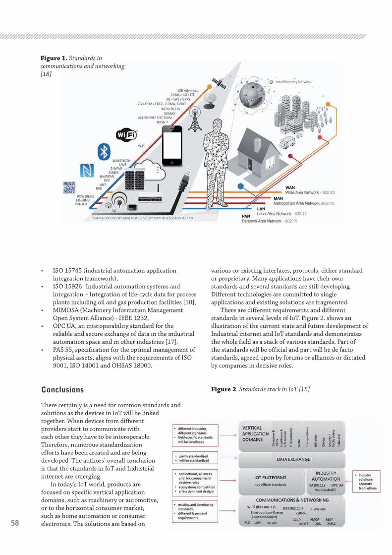
58
• ISO 15745 (industrial automation application integration framework),
• ISO 15926 “Industrial automation systems and integration – Integration of life-cycle data for process plants including oil and gas production facilities [10],
• MIMOSA (Machinery Information Management Open System Alliance) - IEEE 1232,
• OPC UA, an interoperability standard for the reliable and secure exchange of data in the industrial automation space and in other industries [17],
• PAS 55, specification for the optimal management of physical assets, aligns with the requirements of ISO 9001, ISO 14001 and OHSAS 18000.
Conclusions
There certainly is a need for common standards and solutions as the devices in IoT will be linked together. When devices from different providers start to communicate with each other they have to be interoperable. Therefore, numerous standardization efforts have been created and are being developed. The authors’ overall conclusion is that the standards in IoT and Industrial internet are emerging.
In today’s IoT world, products are focused on specific vertical application domains, such as machinery or automotive, or to the horizontal consumer market, such as home automation or consumer electronics. The solutions are based on
various co-existing interfaces, protocols, either standard or proprietary. Many applications have their own standards and several standards are still developing. Different technologies are committed to single applications and existing solutions are fragmented.
There are different requirements and different standards in several levels of IoT. Figure 2. shows an illustration of the current state and future development of Industrial internet and IoT standards and demonstrates the whole field as a stack of various standards. Part of the standards will be official and part will be de facto standards, agreed upon by forums or alliances or dictated by companies in decisive roles.
Figure 2. Standards stack in IoT [15]
Figure 1. Standards in communications and networking [18]
59
INT
ER
NE
T O
F T
HIN
GS
Finland / 1 • 2015STANDARDS IN IOT, INDUSTRIAL INTERNET AND CONDITION-BASED MAINTENANCE
References
[1] Bandyopadhyay D. and Sen J. (2011), “Internet of Things: Applications and Challenges in Technology and Standardization”, Wireless Personal Communications, Vol. 58, pp. 49-69.
[2] Chen S., Xu H., Liu D., Hu B. and Wang H. (2014), “A Vision of IoT: Applications, Challenges and Opportunities With China Perspective”, IEEE Internet of Things Journal, Vol. 1, pp. 349-359.
[3] Chen Y.-K. (2012), “Challenges and Opportunities of Internet of Things”, Design Automation Conference (ASP-DAC), 2012 17th Asia and South Pacific, pp. 383-388.
[4] Coetzee L. and Eksteen J. (2011), “The Internet of Things – Promise for the Future? An Introduction”, IST-Africa 2011 Conference Proceedings, pp. 1-19.
[5] ETSI (2015) “ETSI Standards”, available at: www.etsi.org/standards (accessed February 17, 2015).
[6] Höller J., Tsiatsis V. and Mulligan C. (2014), “From Machine-to-Machine to the Internet of Things: Introduction to a New Age of Intelligence”, Oxford: Academic Press.
[7] IEEE (2015), “IEEE-SA Internet of Things Ecosystem Study”, New York, USA, pp. 1-35.
[8] Industrial Internet Consortium (2014), “Engineering: The First Steps”, available at: www.iiconsortium.org/pdf/IIC_First_Steps_2014.pdf (accessed February 16, 2015).
[9] Industrial Internet Consortium (2015), “Industrial Internet Reference Architecture, Version 1.1”, pp. 1-110.
[10] ISO (2015a), “ISO 15926-2:2003. Industrial automation systems and integration”, available at: http://www.iso.org/iso/home/store/catalogue_tc/catalogue_detail.htm?csnumber=29557 (accessed February 17, 2015).
[11] ISO (2015b), “Standards. ISO 10303”, available at: www.iso.org/iso/home/search.htm?qt=ISO+10303&published=on&active_tab=standards&sort_by=rel (accessed February 17, 2015).
[12] Krco S., Pokric B. and Carrez F. (2014), “Designing IoT architecture(s): A European perspective”, 2014 IEEE World Forum on Internet of Things, WF-IoT 2014, pp. 79-84.
[13] Lopez Research (2014), “Building Smarter Manufacturing With The Internet of Things (IoT)”, Part 2. of “The IoT Series”. San Francisco: Lopez Research LLP.
[14] Mattern F. and Floerkemeier C. (2010), “From the Internet of Computers to the Internet of Things”, Sachs K., Petrov I. and Guerrero P. (Eds.) “From Active Data Management to Event-Based Systems and More”, Darmstadt, Springer, pp. 242-259.
[15] Muhonen T. (2015), “Standardization of Industrial internet and IoT (IoT – Internet of Things) – Perspective on Condition-Based Maintenance”, University of Oulu, Finland.
[16] Muller A., Marquez A.C. and Iung B. (2008), “On the concept of e-maintenance: Review and current research”, Reliability Engineering and System Safety, Vol. 93, pp. 1165-1187.
[17] OPC Foundation (2015), “About. What is OPC?”, available at: opcfoundation.org/about/what-is-opc/ (accessed February 17, 2015).
[18] Postscapes (2014), “Internet of Things Technologies”, available at: http://postscapes.com/internet-of-things-technologies (accessed April 10, 2015)
[19] The International Organization for Standardization (2015), “ISO. Standards”, available at: www.iso.org/iso/home/standards.htm (accessed February 17, 2015).
[20] Vermesan O., Friess P., Guillemin P., Gusmeroli S., Sundmaeker H., Bassi A., Jubert I.S., Mazura M., Harrison M., Eisenhauer M. and Doody P. (2011), “Internet of Things Strategic Research Roadmap”, Internet of Things – Global Technological and Societal Trends, pp. 9-52.
[21] Woodhouse Partnership Ltd (2013), “Assett Management Standards. ISO 55000”, available at: www.assetmanagementstandards.com/resources/ISO55000+introduction+v1.1.pdf (accessed February 17, 2015).
[22] Xu L.D., He W., Li S. (2014), “Internet of Things in Industries: A Survey”, Industrial Informatics, IEEE Transactions 10, pp. 2233-2243.
Tiia MuhonenVTT Technical Research Centre of
Finland, Oulu,
Heikki Ailisto VTT Technical Research Centre of
Finland, Oulu
Pekka Kess University of Oulu,
Finland
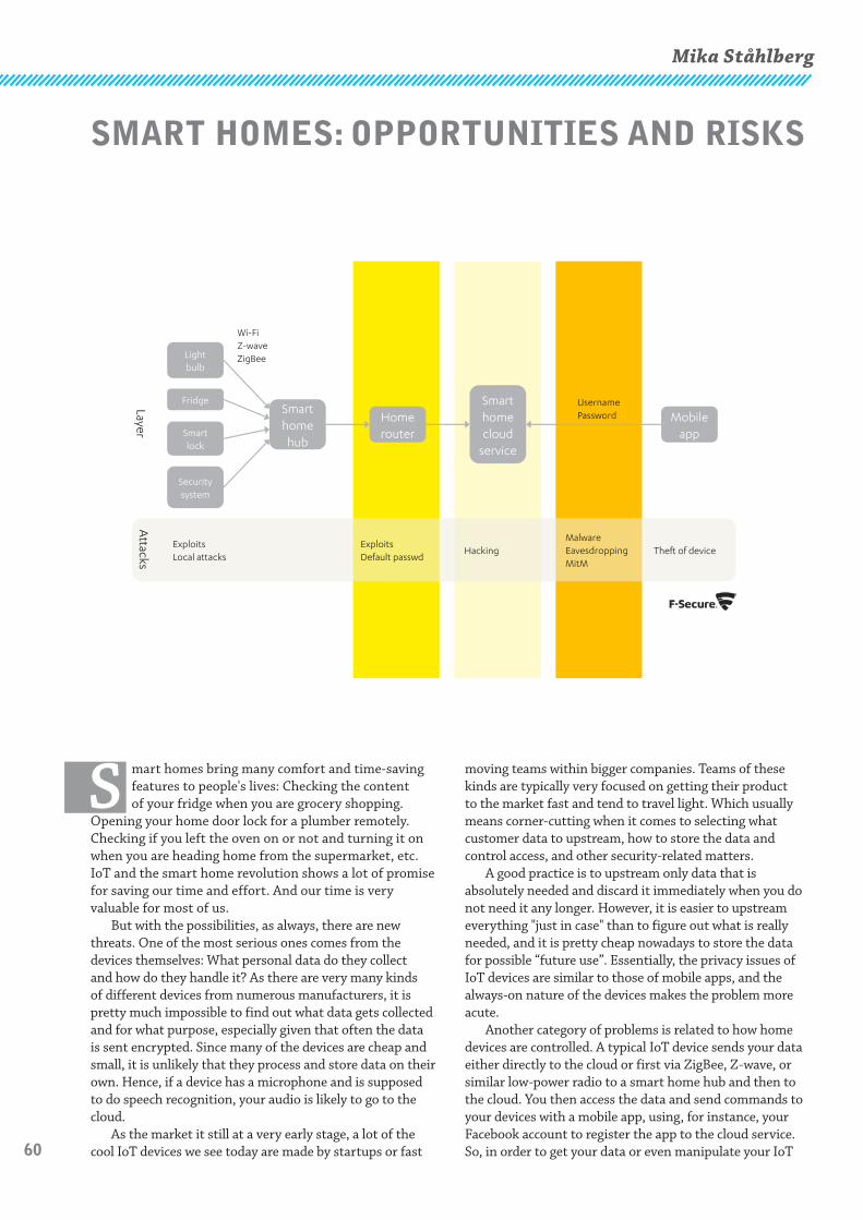
60
SMART HOMES: OPPORTUNITIES AND RISKS
S mart homes bring many comfort and time-saving features to people's lives: Checking the content of your fridge when you are grocery shopping.
Opening your home door lock for a plumber remotely. Checking if you left the oven on or not and turning it on when you are heading home from the supermarket, etc. IoT and the smart home revolution shows a lot of promise for saving our time and effort. And our time is very valuable for most of us.
But with the possibilities, as always, there are new threats. One of the most serious ones comes from the devices themselves: What personal data do they collect and how do they handle it? As there are very many kinds of different devices from numerous manufacturers, it is pretty much impossible to find out what data gets collected and for what purpose, especially given that often the data is sent encrypted. Since many of the devices are cheap and small, it is unlikely that they process and store data on their own. Hence, if a device has a microphone and is supposed to do speech recognition, your audio is likely to go to the cloud.
As the market it still at a very early stage, a lot of the cool IoT devices we see today are made by startups or fast
moving teams within bigger companies. Teams of these kinds are typically very focused on getting their product to the market fast and tend to travel light. Which usually means corner-cutting when it comes to selecting what customer data to upstream, how to store the data and control access, and other security-related matters.
A good practice is to upstream only data that is absolutely needed and discard it immediately when you do not need it any longer. However, it is easier to upstream everything "just in case" than to figure out what is really needed, and it is pretty cheap nowadays to store the data for possible “future use”. Essentially, the privacy issues of IoT devices are similar to those of mobile apps, and the always-on nature of the devices makes the problem more acute.
Another category of problems is related to how home devices are controlled. A typical IoT device sends your data either directly to the cloud or first via ZigBee, Z-wave, or similar low-power radio to a smart home hub and then to the cloud. You then access the data and send commands to your devices with a mobile app, using, for instance, your Facebook account to register the app to the cloud service. So, in order to get your data or even manipulate your IoT
Mika Ståhlberg
Fridge
Smart lock
Security system
Home router
Smart home cloud
service
Mobile app
UsernamePassword
Wi-FiZ-waveZigBeeLight
bulb
ExploitsDefault passwd
MalwareEavesdroppingMitM
HackingExploitsLocal attacks
Theft of device
LayerA
ttacks
Smart home hub

61
INT
ER
NE
T O
F T
HIN
GS
Finland / 1 • 2015
devices, it is sufficient for the attacker to steal or guess your password or to hack the cloud backend of the service. As scary as it is, it currently seems your password will replace your house key. And we know how good people and services are with selecting and keeping passwords safe. (On the other hand, some people store their spare home key under the doormat.)
Current in-the-wild IoT attacks mainly target home routers, set-top boxes, and NAS devices, using factory default passwords or remote code execution exploits. The attacker goal is primarily to form a botnet that can be used for click fraud, denial of service attacks, sending spam, and mining bitcoins. It is more about getting your computing resources than your private data. However, as hackers today steal credit card credentials and sell them to other criminals to make cloned cards and sell them onwards, the same criminal ecosystem will certainly expand to selling access to homes. Local burglars of the future probably will be able to get doors opened and alarms shut down in empty houses as a criminal online service.
Together with the hacker threat, we are facing the privacy one. While traditionally what happens and what is talked about in a home stays within the home, now that can be sent to the cloud. Which means a smart home device maker, Internet service providers, governmental intelligence agencies, etc. can monitor what happens in your home – if they choose – without installing any spy gear. Putting tracking devices into our pockets and installing cameras and microphones in our homes, we are enabling the surveillance from Orwell's “1984”, not because it is forced on us, but because we want it.
The IoT transformation has a business angle as well, and not only because companies are installing sensors into their own products and to their premises. Their employees are bringing personal gadgets to the office and to the meeting rooms, buying gadgets without corporate IT's approval, and connecting those to the corporate network. So, IoT cloud backend systems process a lot of business critical data as well.
Examples of current issues and attacks
IoT devices are vulnerable, at least as much as any other Internet-connected devices. They typically run a stripped-down embedded Linux or may not have any OS at all. There may be no support for firmware updates, and the OS may be configured to enable smooth and simple UX rather than solid security. What protects IoT devices at home is not really the lack of vulnerabilities but two things: NAT in your home router and relatively small number of installations. NAT prevents your device from being openly visible on the Internet and the small population makes it less profitable for the attackers to target IoT devices. However, with the growing popularity of Smart Homes, attacking those will be more rewarding for the criminals and that will certainly change the game.
In early 2015, attacks against smart home devices are not really commonplace, but their frequency, size, and
impact are definitely growing rapidly. We briefly mention a few popular types of those.
Home routers hijacking
Hundreds of thousands of home routers around the world are under the control of attackers as of February 20141. Changing the router’s DNS server setting to point to a server under the attacker’s control and perform phishing and click fraud by redirecting the user’s browser to a different IP address is one reason to attack routers. Another is to harness them into a botnet that can be used for bitcoin mining or Denial of Service attacks2.
Even without being hijacked, home routers expose services to the Internet and some of those can be used in DDoS force multiplication (reflection).3
A typical way to compromise routers is by logging into their web administrator interface with default credentials (such as username “admin”, password “admin”). Unfortunately some common home router models expose their web admin interface, a WAN interface by default, also to the Internet. There are also in-the-wild attacks where cross-site request forgery is used to gain access to the router through its local, LAN port4.
Hijacking set-top boxes and NAS devices
Embedded Linux devices, such as DVRs and NAS devices, have been hijacked for cryptocurrency mining5. Today, these attacks typically come in the form of a worm that also tries to find other devices to infect6.
Web cameras hijacking
In late 2014, someone in Russia set up a web site that provided live video footage of thousands of web cams around the World7, including some 4600 cameras in the USA. These cameras were CCTV cameras from shops, security cams in homes, nanny cams from nurseries, etc. The site creator had apparently scanned the Internet for web camera interfaces and tried manufacturer default passwords to gain access.
There have been many cases all over the world where laptop web cams were used in extortion or violation of privacy8.
Protecting IoT against attacks
Current approaches to protecting against Smart home / IoT attacks in general can be divided into five categories: 1) end-point software, 2) security gateway, 3) cloud security, 4) patch management, and 5) security hardening. Here, we will only briefly introduce those and mention their limitations.

62
End-point software
A traditional way of protecting devices from malware and other attacks has been to install security software, which comes in such forms as antivirus, personal firewall, anti-spyware, web content filtering, etc., often combined into security suites.
As Gartner estimates that a typical home will have around 500 Internet-connected devices in 20229, installing and maintaining security software on those does not appear feasible. Also, many of those devices will not have any operating system or their OS will not support installing of applications. Furthermore, such popular mobile operating systems as iOS, Android, and Windows Phone have very strict application sandboxes, which makes it extremely challenging to build any meaningful security software for those platforms.
Security gateway
Smart home devices and most of other devices at home are usually connected to the home Wi-Fi or wired Ethernet LAN. The home gateway (router) is therefore a choke point where security of all devices at home can be controlled, at least, when it comes to threats from the Internet. Solutions in this class are separate UTM devices or security features built into home routers.
The challenge with these solutions is that some devices at home are mobile and roam into other networks. Also, since more and more traffic is protected by https or some other cryptographic protocol, providing security by analyzing network traffic is becoming more difficult. Moreover, attacks that use USB memory sticks or other portable disks still remain a problem.
Cloud security
There are many products that try to implement a security gateway in the cloud. Essentially, instead of setting up a gateway device at a choke point in the local network, these solutions use some network setting to redirect the traffic to and from end-points to go through a security gateway in the vendor’s data center. This can be achieved with DNS setting, Browser proxy setting, VPN profile, SMTP, and so on.
Such solutions have the same weaknesses as the local security gateway approach, most importantly, encrypted traffic is a problem. Also, some techniques of redirecting the traffic do not cover traffic of certain types. E.g., SMTP only works for email and web proxy setting is only used for web traffic.
Patch management
Most of real-world malware attacks utilize various software vulnerabilities for getting their code running on the target device. Patch management solutions scan devices or local network for vulnerable software versions
and either instruct the user to install patches or do that automatically for the user.
A clear problem with patch management is that not all attacks involve vulnerabilities in software. There are also attacks which rely on social engineering – tricking the user into installing the malicious code – or on weak or default passwords or various misconfiguration issues. And, of course, for so-called zero-day vulnerabilities there are no patches available. Furthermore, when it comes to IoT, device manufacturers often end the support for their devices earlier than the customers stop using them and, sometimes, the manufacturers are slow with the patches even when the support is still active. Finally, some devices do not even have an update mechanism that the user could use.
Security hardening
There are many ways to reduce the attack surface for a device. As an example, a very effective way to harden a home router against attacks is to disable all administration and UPnP services from the internet/WAN port. Then unpatched vulnerabilities in services are not an issue as they are not running. Furthermore, “default password” attacks can be effectively mitigated by changing the password and preferably also the username into something hard to guess. Unfortunately, security hardening often involves manual work and does not scale well.
What can be done?
In the Internet of Things program, we are exploring ways of combining all the mentioned approaches to benefit from their strengths and mitigate their weaknesses. We want to design a solution that protects “the whole home”, every device that is connected to or visiting the home network, instead of focusing on protecting a single device or a group of devices by installing end-point software.
Popular techniques for detecting attacks and intrusions are based on anomaly detection. Via collaborative analysis of data collected in a large number of home IoT environments, we may be able to understand “normal use” patterns and characteristics and detect intrusions as deviations from those. Of course, there are multiple challenges on the way.
For instance, there are devices, or applications in those, which normal behavior makes them unwanted. In particular, those leaking your sensitive information or sharing it with other parties. Even more technically savvy users usually have no real chance of understanding what kind of data about them is collected and what happens to the data. One potential solution to this problem is to categorize devices and apps by their purpose, functionality, capabilities, etc., and recognize unwanted ones as “anomalous in their category”.
Another source of problems, which was mentioned earlier, is that the simplest way of attacking a smart
63
INT
ER
NE
T O
F T
HIN
GS
Finland / 1 • 2015
home environment is often via taking control over its management app running in a mobile phone or other device, e.g., by exploiting vulnerabilities or guessing passwords. If successful, the attacker gets the power to do whatever the legitimate user can: open locks, turn on appliances, view real-time video, etc. Unfortunately, from the anomaly detection point of view, it may be almost impossible to tell apart the attacker’s actions from normal use. Careful correlating of multiple events over longer periods of time may help, but implementing such effective detection methods while minimizing the number of false positives appears a highly non-trivial problem.
Finally, we want to mention that the wider use of HTTPS complicates the matters, hiding traffic content. On the other hand, we can still observe IP addresses, SNI data, size of requests, and some other metadata. So, it is an interesting challenge to find out what can be detected via metadata-only analysis.
References
[1] BBC: “Hackers take control of 300,000 home routers” <http://www.bbc.com/news/technology-26417441> (Mar 3, 2014)
[2] Krebs on Security: “Lizard Stresser Runs on Hacked Home Routers” <http://krebsonsecurity.com/2015/01/lizard-stresser-runs-on-hacked-home-routers/> (Jan 9, 2015)
[3] SC Magazine: “SSDP reflection DDoS attacks on the rise, Akamai warns” http://www.scmagazine.com/ssdp-reflection-ddos-attacks-on-the-rise-akamai-warns/article/377754/ (Oct 16, 2014)
[4] PC World: Attack hijacks DNS settings on home routers in Brazil <http://www.pcworld.com/article/2602040/attack-hijacks-dns-settings-on-home-routers-in-brazil.html> (Sep 3, 2014)
[5] Wired: “Hackers Turn Security Camera DVRs Into Worst Bitcoin Miners Ever” <http://www.wired.com/2014/04/hikvision/ (Apr 1, 2014) The Register: ” Crooks use Synology NAS boxen to mine Dogecoin, yells Dell” <http://www.theregister.co.uk/2014/06/19/clever_hacker_pops_nases_mines_620000_in_dogecoin/> (Jun 19, 2014)
[6] Fitsec blog: “New piece of malicious code infecting routers and IPTV’s” <http://fitsec.com/blog/index.php/2012/02/19/new-piece-of-malicious-code-infecting-routers-and-iptvs/>(Feb 19, 2012)
[7] CNN: “Russian website streams thousands of private webcams” http://money.cnn.com/2014/11/20/technology/security/hacked-web-cameras-russia/ (Nov 20, 2014)
[8] USA Today: “Calif. youth admits Miss Teen USA 'sextortion' plot” (Nov 12, 2013) <http://www.usatoday.com/story/news/nation/2013/11/12/miss-teen-usa-sextortion-guilty-plea/3510461/>
[9] Gartner: “Gartner Says a Typical Family Home Could Contain More Than 500 Smart Devices by 2022” <http://www.gartner.com/newsroom/id/2839717> (Sep 8, 2014)
SMART HOMES: OPPORTUNITIES AND RISKS
Even more technically savvy users usually have no real chance of understanding what kind of data about them is collected and what happens to the data
Mika StåhlbergF-Secure Corporation
Consortium:
www.iot.fiISSN 2342-6551 (print) ISSN 2342-656X (online)