iot m2m case study analysis
TRANSCRIPT

All material is Copyright © Informa Telecoms & Media
IoT M2M Case study Real network projects

2 2
Case study 1
LTE TDD RURAL COVERAGE for M2M services
3 3
Project scenario
Provide LTE coverage for M2M forest surveillance over mountainous
rural areas
Technical project requests:
1. Check for high temperature/gas/fire alerts
2. Check for video confirmations on alerting
3. All in one board architecture
4. Autonomous power – solar or PoE
5. Connect through LTE to a main server
6. Use C-RAN connectivity to minimize implementation

4 4
Project scenario
Provide LTE coverage for M2M forest surveillance over mountainous
rural areas
Technical project requests:
1. Check for high temperature/gas/fire alerts

5 5
Project scenario
Provide LTE coverage for M2M forest surveillance over mountainous
rural areas
Technical project requests:
2. check for video confirmations on alerting
6 6
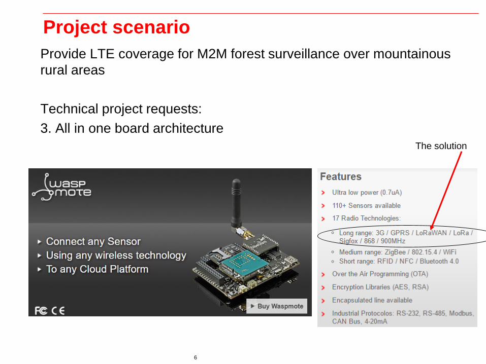
Project scenario
Provide LTE coverage for M2M forest surveillance over mountainous
rural areas
Technical project requests:
3. All in one board architecture
The solution
7 7
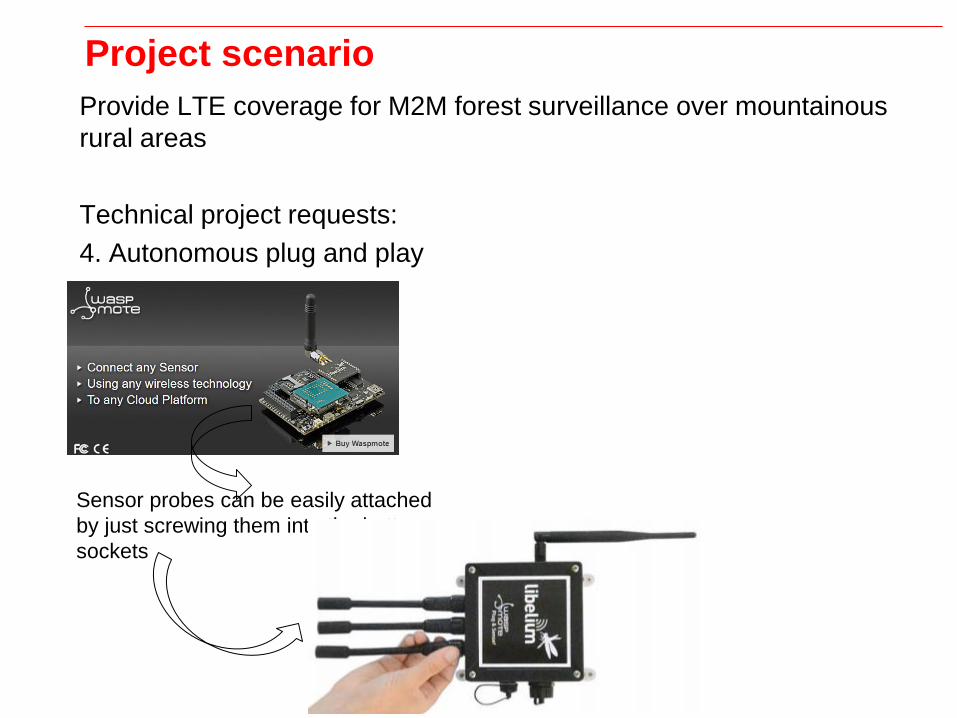
Project scenario
Provide LTE coverage for M2M forest surveillance over mountainous
rural areas
Technical project requests:
4. Autonomous plug and play
Sensor probes can be easily attached
by just screwing them into the bottom
sockets

8 8
Project scenario
Provide LTE coverage for M2M forest surveillance over mountainous
rural areas
Technical project requests:
4. Autonomous power – solar or PoE
Sensor probes can be easily attached
by just screwing them into the bottom
sockets
9 9
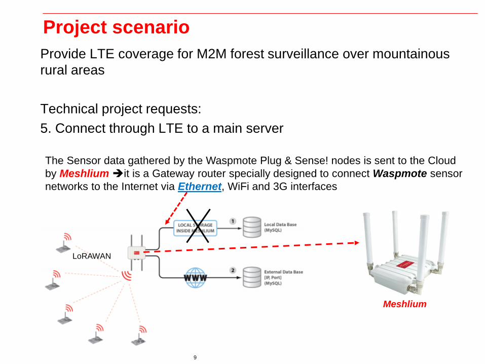
Project scenario
Provide LTE coverage for M2M forest surveillance over mountainous
rural areas
Technical project requests:
5. Connect through LTE to a main server
The Sensor data gathered by the Waspmote Plug & Sense! nodes is sent to the Cloud
by Meshlium it is a Gateway router specially designed to connect Waspmote sensor
networks to the Internet via Ethernet, WiFi and 3G interfaces
Meshlium
LoRAWAN

10 10
Project scenario
Provide LTE coverage for M2M forest surveillance over mountainous
rural areas
Technical project requests:
5. Connect through LTE (3.6 GHz) to a main server
The Sensor data gathered by the Waspmote Plug & Sense! nodes is sent to the Cloud
by Meshlium it is a Gateway router specially designed to connect Waspmote sensor
networks to the Internet via Ethernet, WiFi and 3G interfaces
Meshlium

11 11
Project scenarioTechnical project requests:
5. Connect through LTE (3.6 GHz) to a main server
Forest shelter – local aggregator
Indoor shelter VoIP,
data/internet and O&M
services
12 12
Project scenario
Technical project requests:
5. Connect through LTE (3.6 GHz) to a main server
Why LTE ???
Among proposed 3GPP technologies with non-dominant standardized
solution so the most popular due to its cost effectiveness and simplicity
on network implementation is the LTE-A.

13 13
Project scenario
Technical project requests:
5. Connect through LTE (3.6 GHz) to a main server
Why LTE 3.6 GHz ??
In Greece LTE 3,6 GHz is an unused band
Project has been supported by government, through EU funding.
Greek frequency authorities (EETT) has allocated the 3.6 GHz band free
of charge to the Rural project since it is unused so far
Two channel bandwidths have been reserved:
- 3.6 GHz 30 MHz channel bandwidth
- 3.8 GHz 30 MHz channel bandwidth
14 14
Project scenario
Technical project requests:
5. Connect through LTE (3.6 GHz) to a main server
Why LTE 3.6 GHz TDD???
In Greece LTE 3.6 GHz TDD is an unused band, leaving other TDD sub-
bands available for other future services

15 15
Project scenario
Technical project requests:
6. Use C-RAN connectivity to minimize implementation
Why LTE C-RAN ???
Most world dominant vendors are proposing the LTE-A network
architecture and functionality to support the C-RAN approach and to
migrate towards 5G.
C-RAN concept is proposed to be based on a centralized baseband
processing pool equipment serving a number of clustered distributed
radio access nodes (RRUs).
Furthermore in legacy operator networks such as LTE-A and
Heterogeneous Networks, where coordinated functionality and real-time
processing is essential to performance interference as well as mobility
and synchronization improvements, the cloud RAN approach is easily
accommodated.
16 16
Project scenario
Technical project requests:
6. Use C-RAN connectivity to minimize implementation
Why LTE C-RAN ???
cell planning principles are quite similar to LTE-A with extra restrictions
and demands adapting to the specific traffic and service.
Ericsson & Huawei have lately (early 2016) proposed a combination of
powerful software features to combine cloud RAN with LTE-A technology
and deliver extreme application coverage with huge peak cell
throughputs over existing 4G operator infrastructures, in an effort
towards 5G networks aligned with 3GPP and 5GPPP standards and
proposals.

17 17
The project architecture
C-RAN architecture use Huawei eA360 Customer Premise
Equipment (CPE) at 3.6-3.8 GHz
Meshlium

18 18
The project architecture
C-RAN architecture use Huawei DBS3900 eNodeB technology with
RRU3232 at 3.6-3.8 GHz

19 19
The project architecture
C-RAN architecture use Huawei DBS3900 eNodeB technology with
RRU3232 at 3.6-3.8 GHz

20 20
The project architecture
C-RAN architecture use Huawei DBS3900 eNodeB technology with
BBU3232 at 3.6-3.8 GHz

21 21
The project architecture
C-RAN architecture use Huawei eA360 Customer Premise
Equipment (CPE) at 3.6-3.8 GHz
In such architectures a large number of remote Remote Radio
Handlers/Remote Radio Units (RRH/RRU) are deployed over a large
geographical area, all connected over front haul fibre links (dark fibre
links), towards a centralized pool Base Band Unit (BBU) on cloud server
with typical cell coverage ranges of 15-20 Km over fibre links for LTE-A
solutions.
It is widely accepted that using RRH/RRU distributed units over radio
interface introduces advanced technologies over radio access network,
moving processing load functions to the cell edge devices (Mobile Edge
Computing solutions) and exploiting IP/ethernet with emphasis to MPLS
over optical network technology for the RAN transmission and backhaul
network topology.

22 22
The project architecture
C-RAN architecture use Huawei eA360 Customer Premise
Equipment (CPE) at 3.6-3.8 GHz
Such a design facilitates any kind of traffic over a well-planned LTE-A
network including traditional IP subscriber web traffic, cloud services,
sensor based traffic as well as generic IoT services of any kind.

23 23
The project architecture
C-RAN settings activate TTI bundling
What is TTI bundling?
TTI bundling is signaled by rrcConnectionReconfigution.
You can see in 3GPP TS36.331 6.3.2. Key word is ttiBundling and MAC-
MainConfig
There are thresholds defined at the eNB,
This trigger condition shall be checked with every UL transmission of the
UEs and if the trigger condition is fulfilled, the eNB shall inititate the
process to start TTI bundling for the UE.
24 24
The project architecture
C-RAN settings activate TTI bundling
What is TTI bundling?
This feature is activated in eNB as RRCReconfigurationRequest during
the intial PDP context for default bearer established.
Again device must be supported as device capabilities message. After
that UL will be automatically group every 4 TTI.
Re-transmittion of NACK is corrected at 9 sub-frames later. Basically
when device is moved around at cell edge the errors of PUSCH is
overwhelming therefore TTI bundling is reduced the overhead and
resources of HARQ - MAC layer.
Note: in Rel 10 it might not be allowed to enable both Semi-Persistent
Scheduling and TTI bundling at the same time.
25 25
The project architecture
C-RAN settings activate TTI bundling
What is TTI bundling?
Like If the UE has gone in bad radio condition or cell edge where the
Current Modulation and coding scheme has gone below or equal to the
threshold defined for triggerring the TTI bundling.
If TTI bundling measurements are ongoing and the percentage of
NACKed transmissions is greater than Bler threshold for TTI bundling.
Based on these criterion, eNB can trigger the TTI bundling for the UE.
Similarly if the UE moves back again to good radio condition the eNB will
ask the TTI bundlng to be turned off.
26 26
The project architecture
C-RAN settings activate TTI bundling
Check also
beside the options present above one could consider using additional
triggers (at the eNB side to start RRC reconfig).
For example:
1. PHR (power headroom) report in addition to measured UE power in
the up-link.
2. Using known eNB tx power and maximal UE power to configure A1
and A2 measurement event (36.331 A1/A2=Serving becomes
better/worst than threshold).
27 27
The project architecture
C-RAN settings activate TTI bundling
Remarks
1. improving the data part (PUSCH) by TTI bundling is not enough, one
need to look on the control channel send over PUCCH (e.g. use
repetition).
2.
2. The implications on the MAC design are all by trivial, for example
how the MAC scheduler works in both UL and DL (if PUCCH
repetition is used) when combining UEs with bundling and few w/o.
28 28
The project architecture
C-RAN settings RRC connected users ???
There is RRC connected user license limit provided by vendor. By
default, this is 60 (as per my knowledge and experience).
As users increase in network, you need to buy license allowing more
users from vendor.
If you guide me which vendor you are working ,I might be able to send
you the license parameter to check.
Secondly, there is product capacity provided by the
Again this can be identified if product version is known.

29 29
The project architecture
C-RAN settings RRC connected users ???
Do not confuse it with applicability while considering 1 ms TTI and 20
MHz BW.
There is difference between theoretical and practical limitations. Specific
equipment has its limitation in processing the load.
This is the reason you are observing challenge in understanding this.
RRC connected user capacity is provided at eNB level.
This is the number of UEs in connected mode at an instance.

30 30
LoRAWAN RAN planning considerations
LoRAWAN technical specs.

31 31
LoRAWAN RAN planning considerations
LoRAWAN technical specs.

32 32
LoRAWAN RAN planning considerations
LoRAWAN technical specs.
Our project scenario

33 33
LoRAWAN RAN planning considerations
LoRAWAN technical specs.
Our surveillance scenario
34 34
C-RAN Design considerations
SINR considerations: The major concern is related to the uplink cell
planning & optimization issues in such a way to guarantee adequate
SINR for accepted service accessibility as well as integrity
(throughput) performance.

35 35
C-RAN Design considerations
SINR considerations
assure the signal-to-noise ration over the uplink receiving levels so that uplink
RRH = arg
uplink
t et on
RRH/RRU unit, otherwise several severe side effects might take place
Suppose that CPE outdoor unit transmits on power level , arg
UE
o t etP and the receiving RRH unit
receives a signal strength RRHSE = ,min
UL
RP , then RRH receiving unit will be able to successfully
decode the received signal under a noisy and interference channel link.
Receiving sensitivity RRHSE
is defined as the minimum receiving signal levelmin
UL
RP ,
depending on the requested CPE outdoor unit transmitted power , arg
UE
o t etP and is given by the
following formula:
, arg
min
( ) ( )UE T R
o t et o o o oUL
R RRH
pathloss j LNA f C
P G GP SE
L L L L L
where jL are the jumper losses on RRH antenna unit, LNAL is the LNA losses if
used, fL are the waveguide (feeder) losses, CL are the feeder connector losses
over LNA.
(1)

36 36
C-RAN Design considerations
SINR considerations
The ideal condition for successful decoding on the receiving RRH unit is:
1R feeder
f pathlossLNA
RRH t BW f
LNA
N LSE N RB N
G
Check next slide
(2)

37 37
C-RAN Design considerations SINR considerations

38 38
C-RAN Design considerations SINR considerations
Substituting (2) on (1) will contribute into the sufficient uplink sensitivity condition on RRH receiving unit
, arg1( ) ( )
R feederUE T Rf pathlosso t et o o o o LNA
RRH t BW f
pathloss j LNA f C LNA
N LP G GSE N RB N
L L L L L G
, arg
1
( ) ( )
R feeder
f pathlossLNA
t BW f pathloss j LNA f C
LNAUE
o t et T R
o o o o
N LN RB N L L L L L
GP
G G
(3)

39 39
C-RAN Design considerations SINR considerations
LTE-A for C-RAN has a superior power control algorithm to compensate for adequate power for
the received level of however there should be further considerations regarding some extra
restrictions since maintaining always condition on equation (3) is not always feasible.
This is because CPE outdoor unit has predefined hardware restrictions on the maximum allowed
transmitted power
Moreover than that there is a maximum allowed uplink power threshold posed by RAN
optimizer to mitigate and keep inter-cell interference as low as possible (an example might be the
Ericsson parameter pMaxServingCell).
Considering these extra restrictions equation (3) is rewritten as follows:
, arg
UE
o t etP
0
UEP
max,
UE
ulP
max, , arg
min
min ,min , ( ) ( )UE UE UE T R
o ul o t et o o o oUL
R RRH
pathloss j LNA f C
P P P G GP SE
L L L L L
(4)

40 40
C-RAN Design considerations SINR considerations
The major problem that RAN designers might face on LTE-A C-RAN planning for IoT
sensor applications is that quite often, due to load (inter-cell interference in the area),
LTE-A CPE outdoor unit might easily be saturated on uplink transmitted power.
This means that the power control algorithm might request (under loaded conditions) CPE
outdoor unit to increase uplink transmitted power , to fulfill the RRH/RRU received
SINR or power level, however the CPE outdoor unit might fail (saturates) since:, arg 0,
UE req
o t et uplinkP P
- Requested CPE outdoor unit transmitted power , arg max,
UE UE
o t et ulP P , hence saturates
since max, , argmin ,UE UE
ul o t etP P = max,
UE
ulP , that is restricted from configured parameter (i.e.
Ericsson parameter pMaxServingCell ).
- Requested CPE outdoor unit transmitted power , arg max,
UE UE
o t et ulP P hence there is
enough power since max, , argmin ,UE UE
ul o t etP P = , arg
UE
o t etP , but on the same time
, arg max,
UE UE UE
o o t et ulP P P as a result fails (saturates) to respond to that power
request because of hardware circuitry restrictions since
max, , argmin ,min ,UE UE UE
o ul o t etP P P = , argmin ,UE UE
o o t etP P = UE
oP saturation due to
power CPE outdoor specifications.

41 41
C-RAN Design considerations SINR considerations
The major problem that RAN designers might face on LTE-A C-RAN planning for IoT
sensor applications is that quite often, due to load (inter-cell interference in the area),
LTE-A CPE outdoor unit might easily be saturated on uplink transmitted power.
Considering both previous conditions it holds that:
Requested ( , arg
UE
o t etP UE
oP ) ( , arg
UE
o t etP max,
UE
ulP )
And as a consequence always:
1R feeder
f pathlossLNA
eNodeB t BW f
LNA
N LSE N RB N
G

42 42
C-RAN Design considerations SINR considerations
Planning Conclusions:
1st Conclusion: C-RAN designers, considering the necessary CPE outdoor unit uplink
connectivity, have to ensure that previous saturation conditions should never happen!!!
2nd Conclusion: Considering all design restrictions as well as the RRH/RRU sensitivity conditions:
max, , argmin ,min , ( ) ( ) 1UE UE UE T R R feeder
o ul o t et o o o o f pathlossLNA
eNodeB t BW f
pathloss j LNA f C LNA
P P P G G N LSE N RB N
L L L L L G
max, , arg
1
min ,min ,( ) ( )
R feeder
f pathlossLNA
t BW f pathloss j LNA f C
LNAUE UE UE
o ul o t et T R
o o o o
N LN RB N L L L L L
GP P P
G G
, arg
1
( ) ( )
R feeder
f pathlossLNA
t BW f pathloss j LNA f C
LNAUE
o t et T R
o o o o
N LN RB N L L L L L
GP
G G
(5)

43 43
C-RAN Design considerations SINR considerations
Planning Conclusions:
2nd Conclusion: Considering all design restrictions as well as the RRH/RRU sensitivity conditions:
Considering strict condition for max, , argmin ,min ,UE UE UE
o ul o t etP P P = UE
oP , r R :
- Initial setting of maximum power max,
UE
ulP parameter configuration on every cell
coverage area r R (i.e. Ericsson parameter pMaxServingCell) shall be such that
max,
UE UE
ul oP P max, , argmin ,UE UE
ul o t etP P UE
oP r R .
Simultaneous power control parameter configuration, combined with maximum
geographical coverage R should be such that: , arg max,
UE UE UE
o t et ul oP P P r R
max, , argmin ,UE UE
ul o t etP P = , arg
UE
o t etP r R max, , argmin ,min ,UE UE UE
o ul o t etP P P = UE
oP r R
ensuring condition , arg
UE
o t etP r R .

44 44
C-RAN Design considerations SINR considerations
Planning Conclusions:
3nd Conclusion: A good C-RAN proposal is to use a design margin , so that any Noise and
Interference peaks will be over-dimensioned and absorbed on initial design.arg 3mP dB
max, , arg
arg
min ,min , ( ) ( ) 1UE UE UE T R R feeder
o ul o t et o o o o f pathlossLNA
eNodeB t BW f m
pathloss j LNA f C LNA
P P P G G N LSE N RB N P
L L L L L G
arg
max, , arg
1
min ,min ,( ) ( )
R feeder
f pathlossLNA
t BW f m pathloss j LNA f C
LNAUE UE UE
o ul o t et T R
o o o o
N LN RB N P L L L L L
GP P P
G G
arg
, arg
1
Power Control decision ( ) ( )
R feeder
f pathlossLNA
t BW f m pathloss j LNA f C
LNAUE
o t et T R
o o o o
N LN RB N P L L L L L
GP
G G
(6)
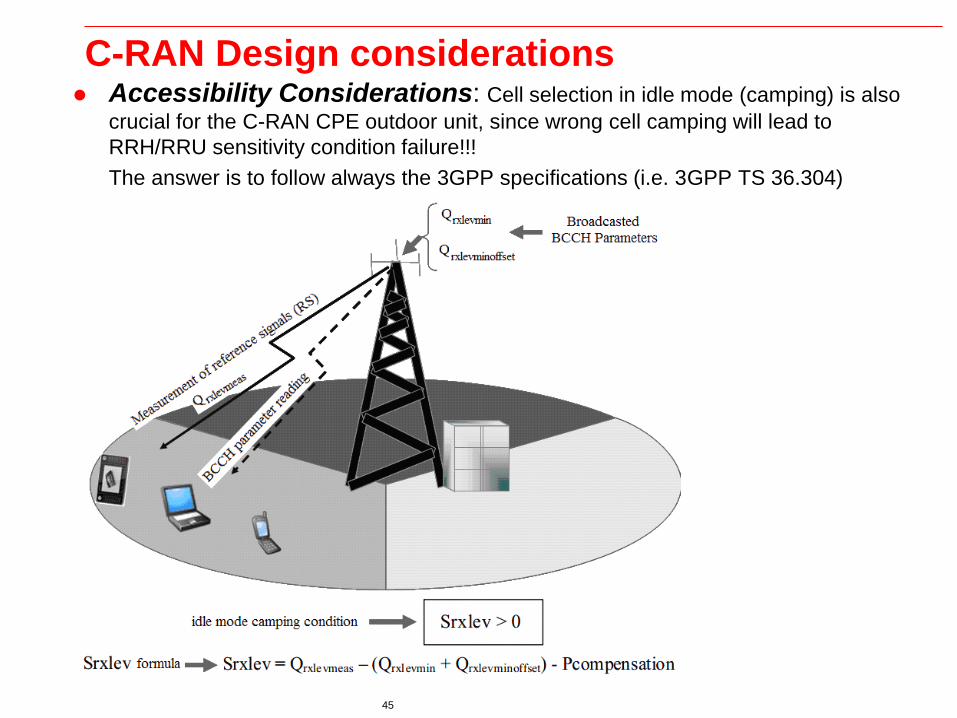
45 45
C-RAN Design considerations Accessibility Considerations: Cell selection in idle mode (camping) is also
crucial for the C-RAN CPE outdoor unit, since wrong cell camping will lead to
RRH/RRU sensitivity condition failure!!!
The answer is to follow always the 3GPP specifications (i.e. 3GPP TS 36.304)
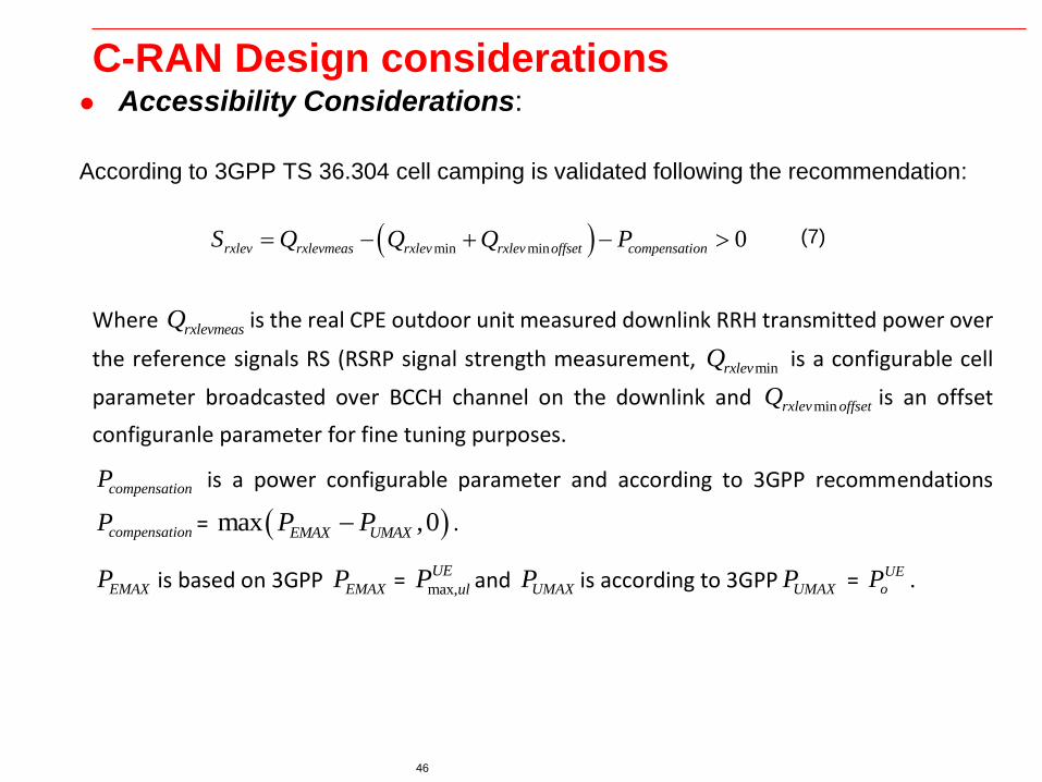
46 46
C-RAN Design considerations Accessibility Considerations:
According to 3GPP TS 36.304 cell camping is validated following the recommendation:
min min 0rxlev rxlevmeas rxlev rxlev offset compensationS Q Q Q P
Where rxlevmeasQ is the real CPE outdoor unit measured downlink RRH transmitted power over
the reference signals RS (RSRP signal strength measurement, minrxlevQ is a configurable cell
parameter broadcasted over BCCH channel on the downlink and minrxlev offsetQ is an offset
configuranle parameter for fine tuning purposes.
compensationP is a power configurable parameter and according to 3GPP recommendations
compensationP = max ,0EMAX UMAXP P .
EMAXP is based on 3GPP EMAXP = max,
UE
ulP and UMAXP is according to 3GPP UMAXP = UE
oP .
(7)

47 47
C-RAN Design considerations Accessibility Considerations:
Substituting into (7) we could get the updated cell camping suitability condition:
min min max,max ,0UE UE
rxlev rxlevmeas rxlev rxlev offset ul oS Q Q Q P P
Following nominal cell planning and considering the LTE-A outdoor unit cell selection to guarantee the equation (5) sensitivity conditions, cell planners should always select camping parameters so that:
- In every geographical cell coverage area r R condition to be fulfilled is
min minrxlev rxlev offsetQ Q rxlevS r R , so that always 0rxlevS
- In every geographical cell coverage area r R condition to be fulfilled is max,
UE UE
ul oP P
r R , so that always max,max ,0UE UE
ul oP P = 0 r R 0rxlevS , r R

48 48
C-RAN Design considerations
Throughput considerations.
Throughput depends on SINR, pathloss as well as LoS conditions
Follow excel file, provided by instructor, for further analysis