ios app store google play - segensolar
TRANSCRIPT
340-0
0053-0
1
Google playiOS App Store
6 CEI Auto Test/Power limit function Introduction
7
10
12
11
4.6
4.7 DRED Connection
4.8 Earth Fault Alarm
18
19
24
25
28
17
17
4.9
209 Trouble shooting
4.11 special backup application
2813 Maintenance
2.3 Special illustration 03
07
06
05
16
16
16
15
17
15
14
13
11
10
08
4.12 Special adjustable setpoints 17
06
4.10
Reload
● If there are more than 3 PV strings on input side, an additional fuse installing will be suggested. An earthing photovoltaic system
need to connect an Arc fault detector on DC side.
1 Introduction
Before using the inverter, please read all instructions and cautionary markings on the unit and this manual. Store the manual where
it can be accessed easily.
The EM series inverter of Jiangsu GoodWe Power Supply Technology Co. Ltd. (hereinafter referred to as GoodWe) strictly conforms to
related safety rules in design and test.
Safety regulations relevant to the location shall be followed during installation, operation and maintenance.
Improper operation may have a risk of electric shock or damage to equipment and property.
01
2 Important Safety Warning
02
Caution!
Failure to observe a warning indicated in
this manual may result in injury.
Danger of high voltage and electric shock!
Danger of hot surface!
Components of the product can be recycled.
This side up; the package must always be
transported, handled and stored in such a way
that the arrows always point upwards.
No more than six (6) identical packages may
be stacked on each other.
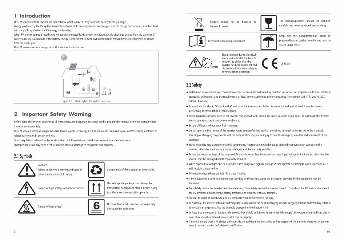
The EM series inverters (hybrid) are bidirectional which apply to PV system with battery to store energy.
Energy produced by the PV system is used to optimize self-consumption; excess energy is used to charge the batteries, and then feed
into the public grid when the PV energy is adequate,
When PV energy output is insufficient to support connected loads, the system automatically discharge energy from the batteries if
battery capacity is abundant. If the battery energy is insufficient to meet own consumption requirements, electricity will be drawn
from the public grid.
EM series inverter is design for both indoor and outdoor use.The
Figure 1-1 Basic hybrid PV system overview
2.1 Symbols
Product should not be disposed as
household waste.
CE Mark
Keep dry; the package/product must be
protected from excessive humidity and must be
stored under cover.
Signals danger due to electrical shock and indicates the time (5minutes) to allow after the inverter has been turned off and disconnected to ensure safety in any installation operation.
The package/product should be handled
carefully and never be tipped over or slung.
2.2 Safety
● Installation, maintenance and connection of inverters must be performed by qualified personnel, in compliance with local electrical
standards, wiring rules and the requirements of local power authorities and/or companies (for example : AS 4777 and AS/NZS
3000 in Australia).
● To avoid electric shock, DC input and AC output of the inverter must be at least 5 minutes before be disconnected and wait
performing any installation or maintenance.
● The temperature of some parts of the inverter may exceed 60℃ during operation. To avoid being burnt, do not touch the inverter
during operation. Let it cool before touching it.
● Ensure children are kept away from inverters.
● Do not open the front cover of the inverter. Apart from performing work at the wiring terminal (as instructed in this manual),
touching or changing components without authorization may cause injury to people, damage to inverters and annulment of the
warranty.
● Static electricity may damage electronic components. Appropriate method must be adopted to prevent such damage to the
inverter; otherwise the inverter may be damaged and the warranty annulled.
● Ensure the output voltage of the proposed PV array is lower than the maximum rated input voltage of the inverter; otherwise the
inverter may be damaged and the warranty annulled.
● When exposed to sunlight, the PV array generates dangerous high DC voltage. Please operate according to our instructions, or it
will result in danger to life.
● PV modules should have an IEC61730 class A rating.
● If the equipment is used in a manner not specified by the manufacturer, the protection provided by the equipment may be
impaired.
● Completely isolate the inverter before maintaining. Completely isolate the inverter should :Switch off the DC switch, disconnect
the PV terminal, disconnect the battery terminal, and disconnect the AC terminal.
● Prohibit to insert or pull the AC and DC terminals when the inverter is running.
● In Australia, the inverter internal switching does not maintain the neutral integrity, neutral integrity must be addressed by external
connection arrangements like the example proposed in the diagram 4.10.
● In Australia, the output of backup side in switchbox should be labeled 'main switch UPS supply', the output of normal load side in
switchbox should be labeled 'main switch inverter supply'.
Refer to the operating instructions

● Don’t connect EM series in the following ways:
①Back-up port should not be connected to grid;
②Back-up port should not be connected in parallel;
③The single PV panel string should not be connected to two or more inverters.
① ② ③
PV PV
Load
Back-Up On-Grid Back-Up Back-Up
● The inverter can exclude the possibility of DC residual currents to 6mA in the system,Where an external RCD is required in addition
to the built-in RCMU, type A RCD must be used to avoid tripping。
Installation position shall not prevent access to the disconnection means;●
● The PV- is not grounded as default configuration.
④ ⑤
⑥
④One EzMeter should not be used for multi inverters. One or more CTs of EzMeter connected together on the same fire cable.
⑤One battery (bank) connect with multi inverters.
⑥Ongrid or backup port should not be connect AC generator.
Accepted house loads for back-up side includes: Television, Computer, Fridge, Fan, illumination lamps, microwave oven, electric rice
cooker, routers etc.
Unaccepted house loads for back-up side includes: air conditioner, water pump, heaters, wash machine, electromagnetic oven,
compression engine, hair drier, dust cleaner etc.
2.3 Special illustration
2.3.1 Back-Up loads
2.3.2 Back-Up Overload
Battery will act a protective charge/discharge current limitation under any condition as below:
a. Battery SOC lower than 1-DOD;
b. Battery voltage lower than discharge voltage
c. Ambient temperature higher than 45℃;d.Lithium Battery communication abnormal.
When charge/discharge current limitation happens:
a.Under on-grid mode, battery charge/discharge might appears abnormal;
b.Under off-grid mode, Back-up supply will shut off.
Note: Under off-grid mode, if Backup supply shut off because of battery low SOC or battery voltage, then PV power will all
charge battery till battery SOC reaches 40%+(1-DOD)/2, when back-up supply will be waken again.
2.3.3 Battery protection
d. For lead-acid batteries connecting with GoodWe Hybrid inverter, the SOC is calculated on inverter side. As lead-acid battery
has various brands and battery ages, the SOC calculation will has deviation from the real SOC.
e. For lead-acid battery band, the SOC calculated is the total SOC of the whole bank, thus if there is any uniformity deviation
between different battery cells, which will cause overcharge or over-discharge on some cells, further will damage the cell(s)
and shorten battery bank life.
f. For lead-acid batteries, please honestly refer to your battery specifications to set Battery Capacity, Charge/discharge
current, Charge Voltage and Discharge Depth etc. Default Discharge Voltage is 42V (non-editable). Unsuitable settings for
lead-acid batteries will possiblly lead to inaccurate battery SOC, weak battery lifespain, or further battery damage.
g. For damage caused by unsitable settings, battery out of warranty, battery quality etc, it is ivnerter-irresponsible.
For details, please refer to battery user manual.
2.3.4 Lead-Acid Batteries Used in Hybrid system
2.3.5 Statement on Wiring Connection in SPLIT Grid System
In SPLIT grid system, there is a solution to make hybrid inverter work under on-grid condition, but he exporting power and load
power might be inaccurate as the nominal hybrid inverter output is 230V and there could be loads of both 110V and 220V.
For GoodWe EM inverters, it is able to supply a continuous 2300VA output or max 3500VA in less than 10 seconds on back-
up side, to support back-up loads.And the inverter contains self-protection derating at ambient temperature 45℃, and
further will shut down at ambient temperature 60℃.
03 04
G
a.If install the lead-acid batteries,please contact the GoodWe Service Center first([email protected])
c.For Lead-Acid batteries, we do not have temperature compensation. Customers need set battery charge voltage
based on the real working temperature.
b.Do not provide the warranty if unconfiremed.

05 06
Figure 3.3-1
Mounting location should be selected based on the following aspects:
● The installation method and mounting location must be suitable for the inverter's weight and
dimensions.
● Mount on a solid surface.
● Select a well ventilated place sheltered from direct sun radiation.
● Install vertically or tilted backward by max 15°. The device cannot be installed with a sideways tilt. The connection area must point
downwards. Refer to Figure 3.3-1.
3.3 Selecting The Mounting Location
●
● For the convenience of checking the LED lights and possible maintenance activities, please install the inverter at eye level.
● Inverters should NOT be installed near inflammable and explosive items. Any strong electro-magnetic equipment should be kept
away from installation site.
● Product label and warning symbol shall be clear to read after installation.
● Please avoid direct sunlight, rain exposure, snow lay up when install.
In order to achieve optimal performance, the ambient temperature should be lower than 45 °C.
Direct Sunlight Rain Exposure Snow Lay upNo direct sunlight No Rain Exposure No Snow Lay up
3.1 Packing List
3 Installation
Before installation, please inspect the unit. Be sure that nothing inside the package is damaged. You should have received the
following items inside of package:
Max
15°
Wall-mounted
Bracket×1Inverter×1 Positive DC Plug×2
or
Negative DC Plug×2
or
Battery cover × 1
EzMeter & CT × 1
Battery terminal × 2
User Manual×1
Usermanual
Quick Installation Guide×1 Wi-Fi Configuration×1
Wi-Fi
Configuration
Instruction of
Fast Installation
Expansion Bolts×6Hexagon head
screw × 2 Pan head screw × 6
Waterproof terminal × 2
3.2 Product Overview
1 2 3 4 5 6
7
1. 2. Battery input terminals3. Wi-Fi Box port4. Communication port
5. Back-Up port
6. On-Grid port 7. DC Switch (Optional)8. LED Lable
8
PE terminal × 1
PV input terminals
2
EzManage Instruction ×1
EzManage
Instruction

08
Positive shall be red, negative shall be black .
ToB a ttery
To Battery communication cable
To EzMeter communication cable
House Grid
200mm 200mm
Both sides 200mm
07

6~8N.mFigure 4.1-3
Negative connector
Positive connector
Inverter
Special tools are used to stitching
MC4 series AMPHENOL series
Limit buckle can't crimping the wire
63
The terminal can be connected to earth wire.
right It
09 10

*
*The AC line construction shall be such that if the cord should slip in its anchorage, placing a strain on conductors, the
protective earthing conductor will be the last to take the strain. such as the PE line is longer than L and N.
Neutral conductor shall be blue, line conductor shall be black or brown (preferred), protective earth bonding line shall be yellow-green.
Note:
GW5048-EM
GW3648-EM
GW3048-EM
2300VA 25A/30mA
1
1.5
GW5048-EM
GW3648-EM
GW3048-EM
Installation instruction of WIELAND series please refer to Figure 4.3.3-1.
Figure 4.3.3-1
Single capacitive loadpower 0.7kVA,
0.7
11 12

BMS port is used for communication with lithium battery and can be used for both CAN and RS485 communication protocol.
RS485 port is used for communication with expansion devices.
There are two pre-made cables connect to EM inverter, one cable is 3m which is marked "To Battery" should be connected to Li-battery communication port, the other cable is 10m which marked "To EzMeter" should be connected to EzMeter.If not use the battery communication and EM inverter is installed outside,please take out the "To Battery" cable by remove the communication cover, then put the communication cover back and install the waterproof terminal.The“To Meter”communication cable attached on inverter can be extended to max 100m, but for "to battery" cable, we do not suggest any extension.
BMS
NC
NC
CANL
485_B2
CANH
NC
485_A2
Meter
NC
NC
485_B1
485_A1
485_B1
NC
NC
Color
Orange/white
Orange
Green/white
Blue
Blue/white
Green
Brown/white
Brown
Lithium Battery
④ ④To Battery
House Grid
House Grid
inverter's on grid part
485_A1
NC
RS485
NC
NC
485_A
485_A
Color
Orange/white
Orange
Green/white
Blue
Blue/white
Green
Brown/white
Brown
485_B
NC
NC
485_B
13 14
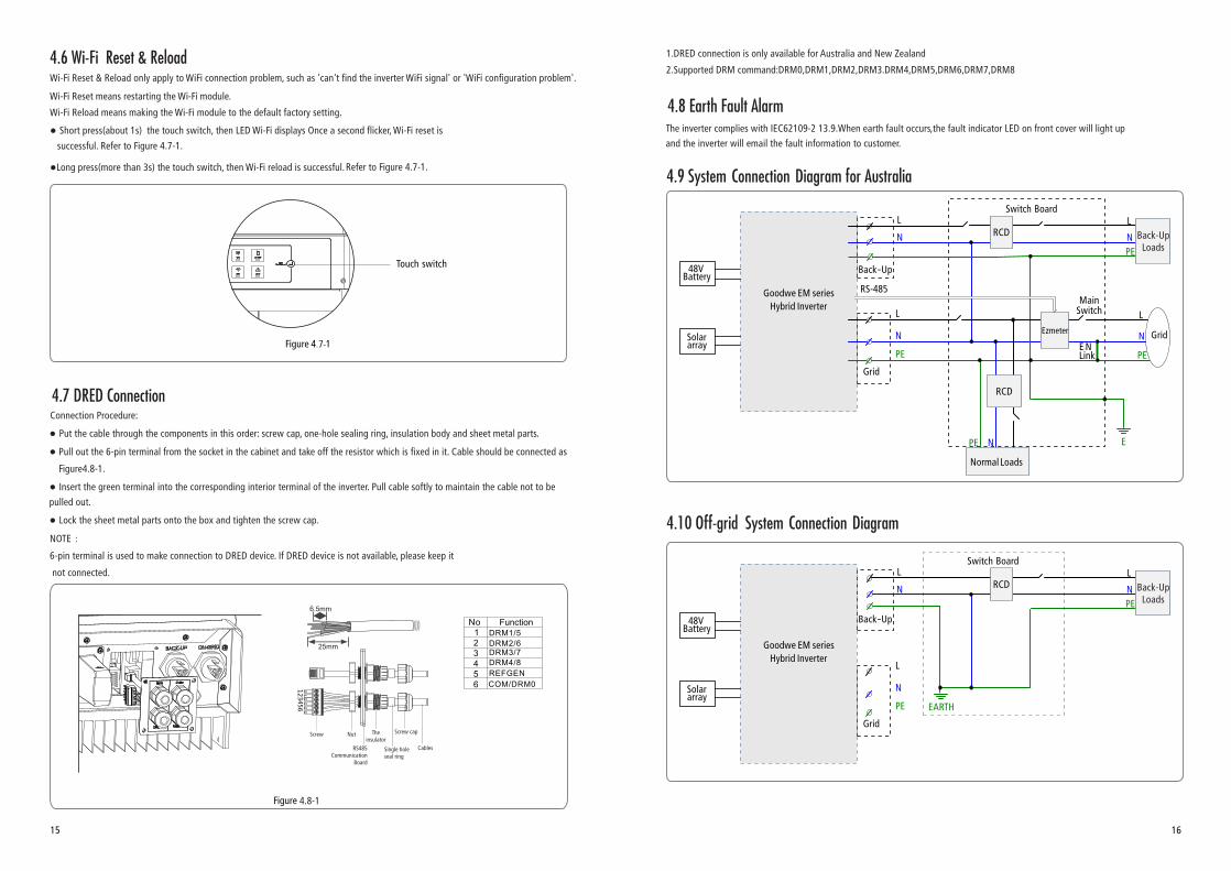
The inverter complies with IEC62109-2 13.9.When earth fault occurs,the fault indicator LED on front cover will light up
and the inverter will email the fault information to customer.
4.8 Earth Fault Alarm
4.6 Wi-Fi Reset & ReloadWi-Fi Reset & Reload only apply to WiFi connection problem, such as 'can't find the inverter WiFi signal' or 'WiFi configuration problem'.
Wi-Fi Reset means restarting the Wi-Fi module.
Wi-Fi Reload means making the Wi-Fi module to the default factory setting.
● press the touch switch, then LED Wi-Fi displays Once a second flicker, Wi-Fi reset is Short (about 1s)
successful. Refer to Figure 4.7-1.
●Long press(more than 3s) the touch switch, then Wi-Fi reload is successful.Refer to Figure 4.7-1.
4.7 DRED Connection
1.DRED connection is only available for Australia and New Zealand
2.Supported DRM command:DRM0,DRM1,DRM2,DRM3.DRM4,DRM5,DRM6,DRM7,DRM8
4.9 System Connection Diagram for Australia
Switch Board
Grid
Back-Up
Goodwe EM series
Hybrid InverterL
NSolar array
48VBattery
L
N
PE
RCD
RCDL
Main Switch
E-N
Link
Normal Loads
NPE E
L
N
PE
GridEzmeter
Back-UpLoadsPE
N
RS-485
7
4.8-1
15 16
NOTE:
6-pin terminal is used to make connection to DRED device. If DRED device is not available, please keep it
not connected.
Pull out the 6-pin terminal from the socket in the cabinet and take off the resistor which is fixed in it. Cable should be connected as
Figure4.8-1.
123456
4.10 Off-grid System Connection Diagram
Switch Board
Grid
Back-Up
Goodwe EM series
Hybrid InverterL
NSolar array
48VBattery
L
N
PE
RCDL
EARTH
Back-UpLoadsPE
N

4.12 Special Adjustable SetpointsThe inverter has field adjustable function,such as trip points,trip times, reconnect times,active and invalid of QU curve,PU curve.
It is adjustable through special software ,if you want to use it ,please contact with after sales.
The methods document of using the software can download from goodwe website or contact with after sales.
EM Series inverter has no LCD screen, it can be controlled via the APP software
(EzManage). For iOS System, please go to AppStore to search for "EzManage", then
download and install it. For Android System, please go to google play to search for
"EzManage", then download and install it. Besides, it can be also installed by scanning
the QR code on the back cover of this manual .
When EM hybrid inverter is working, please use mobile devices to select the SSID of
inverter (Factory defaults is Solar - Wi-Fi, and initial password is 12345678. If any
questions, please refer to Wi-Fi Configuration). After accessing inverter's Wi-Fi network,
you can open the App then configure and monitor the EM system.
5 EzManage Illustration
4.11 Special Back-up Connection
If need maintainance on EM, then just switch SP3T to position 3 as shown above. Thus the loads will be supplied by grid (loads
supply will not be cut off).
Back-up On-grid
The PV Auto Test function of CEI is integrated in EzManage App. For the detailed operation of this function, please check
instructions on EzManage App.
6 CEI Auto Test/Power limit function Introduction
17 18
1
2
3
SP3T 1:Loads is supplied from back-up side
2:Loads is not powered
3:Loads is supplied from grid side
7 LED Lights Illustration
SYSTEM BACK-UP COM BATTERY GRID ENERGY Wi- FAULTFi
ON = SYSTEM IS READY
BLINK = SYSTEM IS STARTING UP
OFF = SYSTEM IS NOT OPERATING
ON = BACK-UP IS READY / POWER AVAILABLE
OFF = BACK-UP IS OFF / NO POWER AVAILABLE
ON = BATTERY IS CHARGING
BLINK 1 = BATTERY IS DISCHARGING
BLINK 2 = BATTERY IS LOW / SOC IS LOW
OFF = BATTERY IS DISCONNECTED / NOT ACTIVE
ON = GRID IS ACTIVE AND CONNECTED
BLINK = GRID IS ACTIVE BUT NOT CONNECTED
OFF = GRID IS NOT ACTIVE
ON = CONSUMING ENERGY FROM GRID / BUYING
BLINK 1 = SUPPLYING ENERGY TO GRID / ZEROING
BLINK 2 = SUPPLYING ENERGY TO GRID / SELLING
OFF = GRID NOT CONNECTED OR SYSTEM NOT OPERATING
ON = Wi-Fi CONNECTED / ACTIVE
BLINK 1 = Wi-Fi SYSTEM RESETTING
BLINK 2 = Wi-Fi ROUTER PROBLEM
BLINK 4 = Wi-Fi SERVER PROBLEM
OFF = Wi-Fi NOT ACTIVE
ON = FAULT HAS OCCURRED
BLINK = OVERLOAD OF BACK-UP OUTPUT / REDUCE LOAD
OFF = NO FAULT
SYSTEM
BACKUP-
COM
BATTERY
GRID
ENERGY
Wi-Fi
FAULT
INDICATOR EXPLANATIONSTATUS
Green Blue Yellow RedGreen Blue Blue Yellow
ON=BMS AND METER COMMUNICATION OK
BLINK1= METER COMMUNICATION OK, BMS COMMUNICATION FAIL
BLINK2= BMS COMMUNICATION OK, METER COMMUNICATION FAIL
OFF= BMS AND METER COMMUNICATION FAIL
The Power limit function can be set by EzManage APP. For the detailed operation of this function, please check
instructions on EzManage App.

8 Work Modes
EM series inverters have the following main work modes based on different conditions:
Mode1:
Energy produced by the PV system priority for local load,
excess energy is used to charge the battery, finally
remaining is delivered to the grid.
Mode2:
If there is no PV, battery energy is used for local load
first, the grid also can supply when the battery capacity
is not enough.
Mode3:
If the grid is fault or there is no grid, the system can still
work, PV and batteries supply energy for local load.
Mode4:
The battery can be charged by the grid, time and power
of battery charging can be set up flexibly.
9 Trouble shooting
Q/A and Trouble Shooting on EM
(+/-
) no
t re
vers
ed
PLEASE CHECK THE FOLLOWING ITEMS AT THE FIRST INSTALLATION, MAKE SURE EVERYTHING IS FINE. OR PLEASE
STOP INVERTER SYSTEM TILL EVERY THING CONFIRMED FINE OR CONTACT GOODWE.
Checking Items Checking Description
Che
ck it
ems
befo
re E
M
star
t-up
Battery connection Confirm the connection between EM and battery : polarity ( +/-) not reversed
PV INPUT connection Confirm the connection between EM and PV panels : polarity(+ /-) n ot reversed
AC OUTPUT Connection power Back-up to loads : polarity Confirm ON-GRID connected to andgrid
(+/-)not reversed
EzMeter / CT connection Make sure EzMeter & CT connected between house loads and grid. and follow
the House→Grid direction sign on CT.
Che
ckin
g it
ems
whe
n st
art
up s
yste
m
CT & EzMeter
connection direction
BMS Communication
Checking details:
1. Check if the COM led on EzMeter triple blinking or not.
2. Or connect Solar-Wifi, check in EzManage App (“Parameters”) if
EzMeter COM state is “OK” or not.
If COM led does not blink, or show “NG” on App, then please check
the connection between EzMeter and EM, like:
1. RJ45 port broken or not;
2. communication cable looses or broken?
3. EzMeter should connect to EM RS485 port.
If everything is Ok, but problem still there, please contact GoodWe
after-sales services.
EzMeter Communication check
NOTE: do not need check if it is Lead-acid battery.
For lithium battery, please check following:
Connect Solar-Wifi, check on EzManage APP (Parameter >>> Battery) if
BMS status shows “BMS Communication OK” or not.
If APP BMS Status on APP says“BMS Communication Failure”, please
reboot EM. if problem is still there, please check further:
a. check on EzManage APP (Basic Setting) if Battery type is right what you
have or not, if not right, please set it right in “Basic Setting”
b. Connection between battery and EM is OK or not;
c. communication cable looses or broken?
d. RJ45 port/cables broken or not;
If everything is Ok, but problem still there, please contact GoodWe after-
sales services.
1. Turn off PV and open Loads, check if R-P led is solid or not.
If “R-P” not solid, please check
a. if CT or EzMeter connected in a wrong direction (the arrow on
EzMeter & CT should point to grid);
b. if connection between EzMeter and CT (port 1 and 4 on EzMeter) is
OK or not.
If both are OK but problem still there, please contact GoodWe after-sales
services.
19 20

Pr
oble
ms
Dur
ing
Ope
rati
on
Problems Solutions
Battery settings on APP
1. For Lithium battery:
connect Solar-Wifi, check on EzManage APP (Parameter >>>
Battery) if Battery Mode is right what you have or not, if not right,
please set it right in “Boost settings”
2. For lead-acid battery:
All the settings should comply with the parameter of the battery
(GoodWe do not suggest the settings for lead-acid batteries)
1. Make sure the voltage of battery is higher than 48V, otherwise
battery cannot start EM up.
If battery voltage is OK, but problem still there, please contact
GoodWe after-sales services.
EM not start up with ONLY
battery connected
EM not start up with ONLY
PV connected
1. Make sure the voltage of PV is higher than 125V;
If everything is OK, but problem still there, please contact GoodWe
after-sales services.
There is no discharge or
output from EM without PV
or PV Power lower than
Load Power
Check items:
1. Communication between EM and EzMeter is OK or not;
2. Make sure Meter power is higher than 150W?
a. EM/battery will not discharge continuously unless Meter Power is
higher than 150W;
b. If Meter Power is higher than 150W, but EM/Battery still not
discharge, then please check Ezmeter & CT connection and
direction;
1. Make sure SOC is higher than 1-DOD ;
Or if battery discharged to below 1-DOD, than battery will only
discharge again when SOC charged to 20%+(1-DOD)/2 and SOC
>105%-DOD(if need
restart the system)
battery discharge immediately, customer can
2. Check on APP if it is set as charge time, during charge time,
battery will not discharge (battery will charge preferentially during
coincident time of charge/discharge)
If everything is OK, but problem still there, please contact GoodWe
after-sales services.
EM/Battery not charge when
PV>P-load
Check items:
1. Check if charge voltage is properly set
2. Check if it is set as only charge time.
3. Check if battery is fully charged or not, or battery voltage reach
“charge voltage” or not.
If everything is OK, but problem still there, please contact GoodWe
after-sales services.
Big Power fluctuation on
Battery charge/dischargeCheck items
Q/A
(Q
uest
ions
and
Ans
wer
s)
Big Power fluctuation on Battery
charge/discharge
Check items
1. Check if there is a fluctuation on load power;
2. Check if there is a fluctuation on PV power on GoodWe Portal.
If everything is OK, please contact GoodWe after-sales Services.
Check items:
1. Make sure BMS communication OK. if not, please try to restart
EM, and check the connection (for lithium battery);
2. Check if EzMeter & CT connected in the right position and to
right direction as on the user manual;
3. Check if total load power is much higher than PV power, or
check if Pgrid on GoodWe Portal is always below 0W.
If PV power is stable but problem still exist, please contact GoodWe
services.
1. Battery does not charge
About Out-Put Power Limit
Cannot see Solar-WiFi signal
on mobile devices
Battery change between
Charge/discharge continually.
Check items:
1. Make sure battery settings are saved successfully;
2. Check if there is a fluctuation on PV power on GoodWe Portal
If PV power is stable but problem still exist, please contact GoodWe
services.
Questions Answers
“Battery Activate” unction
Only use battery when grid is
OFF
On Portal, SOC has a sudden
jump up to 95%?
1. Can set on APP the max out-put power to grid;
2. If Out-put Power Limit set as 0W, then there might still have max
100W to grid.
1. Open or close it on EzManage APP;
2. Used to activate battery when battery is discharged empty;
3. Only used when there is no battery charge.
1. On APP, Open off-grid output function and backup function;
2. Set charge time as 00:00-23:59, discharge time as default
1. Happened on Lead-acid battery or when BMS communication NG on
lithium battery;
2. if battery charge current keep lower than floating charge current set
on APP for 30mins, SOC will be reset to 95% compulsively;
Battery cannot charge to
100%
1. For LG battery, it will stop charge at SOC 95%. It is about LG battery,
normal.
2. Battery will also stop charge when battery voltage reaches charge
voltage set on EzManage APP.
1. Solar- signal will disappear when EM connected to internet; if WiFi
need change settings, can connect to customers’ router to change.
2. If cannot see wifi signal when not connect to router, then please try
to reload wifi (refer to EM user Manual)
3. If still cannot find wifi signal, then restart EM(disconnect everything
including battery and PV/AC
If cannot find Solar- after all these try, please contact GoodWe after-WiFi
sales services.
21 22

Cannot save settings on
EzManage APP
1. Make sure you connected solar-wifi (make sure no other devices
connected) or router (if connected Solar-wifi to router) and on home
page shows connection OK.
2. Make sure EM under waiting mode (on APP) before you change any
settings on EzManage APP ---- disconnect grid/load/battery, only leave
PV connected and then restart EM till see work mode as wait on APP.
If all these try does not help, please contact GoodWe services.
1. For lithium battery, please make sure BMS
communication OK;
2. Please check if battery voltage is lower than discharge voltage
set on APP
3. Make sure no short-cut on Battery connection side.
Battery switch trip
Lithium battery connection
Limitation on Backup Loads
NO-ALLOWED connection
For connection of Ezconverter/battery and EM, please refer to battery
connection SOP, chose right battery brand and fill in battery capacity
manually.
1. For Inductive Loads (like Air conditioner/wash machine/drill), the max
power for each load should be lower than1.5KAV , total power lower
than 2.5KVA
2. For Capacitive Loads, the total max power should be lower than 3KVA
1. Back-up side connected to grid; or backup side connect parallel;
2. Battery connected to grid;
3. One PV string connect to 2 or more PV inputs
Battery configuration
1. Lithium battery must connect BMS communication;
2. Nominal voltage for Lead-acid battery is 48V, max charge
voltage 60V;
3. For example, serial connection of 4*12V 100Ah lead-acid
battery, the capacity will still be 100Ah.
An error message will be displayed on the APP if a fault occurs.
Table 8-1 is the Description of Error Message
10 Error Messages
Table 8-1
Error message
Utility Loss
Fac Failure
PV Over Voltage
Over Temperature
Isolation Failure
Ground I Failure
Relay-Check Failure
DC Injection High
EEPROM R/W Failure
SPI Failure
DC Bus High
AC HCT Failure
GFCI Failure
Vac Failure
Battery Over Temperature
Battery Under Temperature
Battery Cell Voltage Differences
Battery Over Total Voltage
Battery Discharge Over Current
Battery Charge Over Current
Battery Under SOC
Battery Under Total Voltage
Battery Communication Fail
Battery Output Short
Description
Grid disconnected
Grid frequency no longer within permissible range
Overvoltage at DC input
Overtemperature on the case
Ground insulation impedance is too low
Overhigh ground leakage current
Relay self-checking failure
Overhigh DC injection
Memory chip failure
Internal communication failure
Overhigh BUS voltage
Output current sensor failure
Detection circuit of ground leakage current failure
Grid voltage no longer within permissible range
Battery Over Temperature
Battery Under Temperature
Li-Ion Battery Cell Voltage Differences
Li-Ion Battery Over Total Voltage
Battery Discharge Over Current
Battery Charge Over Current
Battery Capacity Low
Battery Under Total Voltage
Battery Communication Fail
Battery Output Short
Over Load Back-up Output Over Load
2423

11 Technical Parameters
10
97.6%
Integrated
Wall bracket
-25~60
0~95%
≤4000
Wi-Fi
Nature convection
<25
LED, APP
RS485;CAN
Model
GW3048-EM GW3648-EM GW5048-EM
230
<3%
~1 (Adjustable from 0.8 leading to 0.8 lagging)
GW3048-EM GW3648-EM GW5048-EM
III
230 (±2%)
50/60 (±0.2%)
3500, 10sec
25 26
4K4H
Outdoor & indoor
Grade1、2、3
Technical Data
Battery Input Data
Battery Type
Nominal Battery Voltage (V)
Max. Charging Voltage (V)
Max. Charging Current (A)
Max. Discharging Current (A)
Charging Strategy for Li-Ion Battery
Charging for Lead-acid BatteryStrategy
AC Output Data (On-grid)
Nominal Power Output to Utility Grid (W)
Max. Apparent Power Output to Utility Grid (VA)
Nominal Ouput Frequency (Hz)
Nominal Output Voltage (V)
Max. AC Current Output to Utility Grid (A)
Max. AC Current From Utility Grid (A)
Battery Capacity (Ah)
Max. Apparent Power from Utility Grid (VA)
[1]
[1]
[2]
AC Over Current Protection(A)
AC Backfeed Current(A)
PV String Input Data
Max. DC Input Power (W)
Max. DC Input Voltage (V)
MPPT Range (V)
Start-up Voltage (V)
MPPT Range for Full Load (V)
Nominal DC Input Voltage (V)
Max.Input Current (A)
Max.Short Current (A)
No.of MPPT Trackers
No.of Strings per MPPT Tracker
[4]
PV Over Current Protection(A)
PV Backfeed Current(A)
DC Overvolage Category
[3]
Maximum output fault current(peak and duration)
Output Inrush Current (peak and duration)
Input Inrush Current (peak and duration)
Output Power Factor
Output THDi (@Nominal Output)
AC Overvoltage Category
External Environment Pollution Degree
Cooling
Noise (dB)
User Interface
Communication with BMS
Communication with Meter
Weight (kg)
Size (Width*Height*Depth mm)
Mounting
Output THDv (linear load)
Efficiency
Max. Efficiency
General Data
Operation Temperature Range (℃)
Relative Humidity
Moisture Location Category
Protection
Operation Altitude (m)
Communication With Portal
Storage Temperature (℃)
Anti-islanding Protection
Output Over Current Protection
Output Short Protection
Output Over Voltage Protection
Max. Battery to Load Efficiency
Europe Efficiency
MPPT Efficiency
Automatic Switch Time (ms)
Back-up Over Current Protection(A)
Output Inrush Current (peak and duration)
Maximum output fault current(peak and duration)
Nominal Output Voltage (V)
Nominal Output Freqency (Hz)
PV String Input Reverse Polarity Protection
Insulation Resistor Detection
Residual Current Monitoring Unit
Environment Category
AC Output Data (Back-up)
Max. Output Apparent Power (VA)
Peak Output Apparent Power (VA) [7]
Max. Output Current (A)
50/60
3000
48
Li-Ion or Lead-acid
50
50~2000
≤60 (Configurable)
Self-adaption to BMS
3-stage adaptive with maintenance
3900
550
100~500
125
280~500
360
11/11
13.8
0
2
1
II
50
4600 6500
170~500 230~500
11/1111
13.8/13.8 13.8/13.8
21
3680 5000[5]
5300
1613.6 22.8 [6]
23.6
10
<3%
2300
94.5%
97%
99.9%
Integrated(AFD)
Integrated
Integrated
Integrated
Integrated
Integrated
-30~65
347*432*175
16 17 17
RS485
21
30
55A 5us
60A 3s
55A 2us
43A 10s
0
3000 3680 5000[5]
43A,0.2s
30A

[1] For lead-acid battery, default charge current is 0.15C, which is can be configurable up to 0.5C by APP EzManage and cannot exceed
50A. C means the battery capacity, such as the battery capacity is 100Ah, default charge current 0.15C is 0.15 * 100A = 15A.
For Li-Ion battery, discharge and charge current follows the command of BMS which doesn't exceed 50A.
[2] Under off-grid mode, then battery capacity should be more than 100Ah.
[3] Maximum operating dc voltage is 530V.
[4] When there is no battery connected, inverter starts feeding in only if string voltage is higher than 200V.
Zref : RA = 0,24 ; XA = j 0,15 at 50 Hz;RN = 0,16 ; XN = j 0,10 at 50 Hz.
[5] 4600 for VDE4105-AR-N & VDE0126-1-1
[6] 21.7A for Australia and New Zealand.
[7] Can be reached only if PV and battery power is enough. 13 Maintenance
Heatsink: please use towel to clean the heatsink once a year;
Torque: please use torque wrench to tighten the AC and battery terminal wiring connection once a year;
Followed 4.2 and 4.3 torque instruction.
DC swith: check the DC switch regularly, active the DC switch 10 times in a row once a year. operating the DC switch
will clean the contacts and will extand the life of the DC switch.
Waterproof covers: check if waterproof covers of RS485 and USB port is fasten once a year.
ID 1419046190
12 Certificates
59
Note
Overvoltage category definition
Category I : applies to equipment connected to a circuit where measures have been taken to reduce transient overvoltage to a
low level.
Category II : applies to equipment not permanently connected to the installation. Examples are appliances, portable tools and
other plug-connected equipment;
Category III: applies to fixed equipment downstream of and including, the main distribution board. Examples are switchgear
and other equipment in an industrial installation;
Category IV: applies to equipment permanently connected at the origin of an installation (upstream of the main distribution
board). Example are electricity meters, primary overcurrent protection equipment and other equipment connected
directly to outdoor open lines.
Environment category definition
Outdoor : the ambient air temperature is -20~50°C, Relative humidity range is 4 % to 100 %, applied to PD3
Indoor unconditioned: the ambient air temperature is -20~50°C, Relative humidity range is 5 % to 95%,applied to PD3
Indoor conditioned: the ambient air temperature is 0~40°C, Relative humidity range is 5 % to 85%,applied to PD2
Pollution degree definition
Pollution degree 1: No pollution or only dry, non-conductive pollution occurs. The pollution has no influence.
Pollution degree 2: Normally only non-conductive pollution occurs. Occasionally, however, a temporary conductivity caused by
condensation must be expected.
Pollution degree 3: Conductive pollution occurs, or, dry, non-conductive pollution occurs which becomes conductive due to
condensation which is expected.
Pollution degree 4: Persistent conductive pollution occurs, for example, the pollution cause by conductive dust, rain and snow.
Moistureparameters
Level
Temperature Range
Humidity Range
3K3
0~+40℃
5%~85%
4K2
-33~+40℃
15%~100%
4K4H
-20~ +55°C
4%~100%
Moisture location category definition
G100 IEC62109-1 IEC62109-2 CEI 0-21 VDE0126-1-1 VDE-AR-N 4105
27
Model GW3048-EM GW3648-EM GW5048-EM
Certifications & Standards
Topology
Safety Regulation
EMC
Grid Regulation
Protective class
Standby Self Consumption (W)
IP rating
IEC62109-1&-2, IEC62040-1
AS/NZS 4777.2:2015; G83/2; G100; CEI 0-21 VDE4105-AR-N; VDE0126-1-1; NRS 097-2-1
EN61000-6-1, EN61000-6-2, EN61000-6-3, EN61000-6-4
EN 61000-4-16, EN 61000-4-18, EN 61000-4-29
<13
I
High Frequency Isolation
IP65
28