ion optics in mass spectrometers
TRANSCRIPT

JOURNAL OF MASS SPECTROMETRYJ. Mass Spectrom. 34, 991–1006 (1999)
SPECIAL FEATURE:TUTORIAL
Ion Optics in Mass Spectrometers
Hermann Wollnik*2. Physikalisches Institut, Universitat Giessen, D-35392 Giessen, Germany
Ion-optical relations are outlined that are relevant to mass spectrometers. Some of the relations are mathe-matically derived and others are only discussed and rationalized. Above all, however, attempts were made toelucidate basic relations and to provide equations that can readily be used for quantitative calculations of realmass spectrometers. Copyright 1999 John Wiley & Sons, Ltd.
KEYWORDS: ion optics; mass spectrometers
INTRODUCTION
Modern mass spectrometers have become complex instru-ments. Therefore, in order to understand the operation ofsuch instruments reasonably well, it is necessary to under-stand how the investigated ions move in the magnetic orelectrostatic fields of these instruments. For this reason, itseems useful to derive basic relations for the motion ofindividual ions and for beams of ions, both in general andin specific ion-optical systems.
FORCES ON CHARGED PARTICLESIN ELECTROMAGNETIC FIELDS
An ion of massm and chargeq, that has been acceleratedby a potential differenceU to a kinetic energyK D qU,moves with the velocityv D p2K/m as long as thisvelocity is small as compared to the velocity of lightc ³ 299 792.458 mmµs�1. For numerical calculations itis advantageous to introduce dimensionless quantitiesK,m, v and q with K D K eV, m D m u, v D v mm µs�1
andq D qe, where�e is the charge of an electron. Hereu stands for the mass of 1/12 of one12C atom. With thesequantities, one finds the velocityv of an ion of K eVenergy andm mass unitsu as1
v ³ 9.8226967√
2K/m .1/
in mm µs�1. To derive Eqn (1) use was made of thefact that the energy equivalent of one mass unitmuc2 is931 493 700 eV, which leads to the numerical value of299 792.458/
p931 493 700³ 9.8226967.
In an electric fieldE measured in V m�1 or in a mag-netic flux densityB measured in TD Vs m�2, charged
* Correspondence to: H. Wollnik, 2. Physikalisches Institut, Univer-sitat Giessen, D-35392 Giessen, Germany.
particles move along curved trajectories. The momen-tary radius of curvature�E or �B of such a trajectory isdetermined (see Fig. 1) by the balance between the cen-trifugal forcemv2/� and the centripetal forcesqE or qvB,assuming thatv is perpendicular toB. Thus one finds theso-called rigidities:
the electrostatic rigidity in:�E D E�E D 2K/q .2a/
the magnetic rigidity in T mm:�B D B�B D mv/q .2b/
with �E D E�E D 2K/q and�B D B�B D mv/q.Since usually the ion’s kinetic energyK is known and
its velocityv is not, one advantageously rewrites Eqn (2b)and describes the magnetic rigidity�B as
�B D B�B ³√
2Km/.9.8226967q/ .2c/
Note that for very high acceleration voltages theion velocity v approaches the velocity of lightc ³ 299 792.458 mmµs�1. In such cases one findsv0 D 9.8226967
√2K.1C �//m0/.1C 2�/ mm µs�1 and
Figure 1. In a magnetic flux density B or in an electrostatic fieldE all ions move along curved trajectories with the momentaryradius of curvature � being determined by the balance betweenthe centrifugal force mv2/� and the electric force Eq or themagnetic force vBq. Here it is assumed that the electrostaticfield E acts in the drawing plane and the magnetic flux densityB is perpendicular to this plane so that its action on a chargedparticle is also within the drawing plane.
CCC 1076–5174/99/100991–16 $17.50 Received 8 January 1999Copyright 1999 John Wiley & Sons, Ltd. Accepted 22 July 1999
992 H. WOLLNIK
�B D B� D√
2Km0.1C �//.9.8226967q/ T mm as wellas �E D E� D .2K/q/.1C �//.1C 2�/ V with � D K/.2m0931 493 700/ where m0 is the mass of theion at rest in mass units u. In some cases themagnetic rigidity �B is also expressed in eV/c,i.e. as �B D .K/q/
√1C 931 493 700.2m0/K/ or �B D
�B/299 792.358³ �B/300 000.In a homogenous magnetic field of constant flux density
B thus all ions move along circles of radius�B if theymoved perpendicularly toB initially. If initially these ionsmoved obliquely toB, the radius�B would be determinedonly from that velocity component that was perpendicularto B. In this case�B is slightly smaller and because theions also have a velocity component parallel toB theymove along a corkscrew line.
In an electric fieldE the trajectories of ions of elec-tric ridgity �E are not necessarily cirles since the fieldE along an ion trajectory is not necessarily constant andperpendicular to the trajectory. This is the case, however,if an ion moves in the middle between cylindrical elec-trodes.
THE MOTION OF IONS THROUGH ANION-OPTICAL SYSTEM
To describe how ions move through a general ion-opticalsystem, one commonly chooses a ‘reference ion’ of massm0, chargeq0 and energyK0 and calls the trajectoryof this ion the ‘optical axis.’ Along this trajectory oneestablishes a coordinatez that is straight in field-freeregions and curved by a radius�0.z/ in regions in whichthe ions are subject to deflecting fields. All other ionsthen are described by their distancesx.z/ and y.z/ fromthis axis and inclinationsa.z/ D dx.z//dz D tan˛.z/ andb.z/ D dy.z//dz D tanˇ.z/ relative to this optical axis.Knowing an ion’s initial coordinatesx.zi/, y.zi/ and incli-nationsa.zi/, b.zi/ at the positionzi one can determine theion’s final coordinatesx.zf/, y.zf/ and inclinationsa.zf/,b.zf/ at the positionzf in a linear or first-order approxi-mation as(
x.zf/a.zf/
)D(.xfjxi/.xf jai/.af jxi/.af jai/
)Ð(x.zi/a.zi/
).3a/(
y.zf/b.zf/
)D(.yfjyi/.yf jbi/.bf jyi/.bf jbi/
)Ð(y.zi/b.zi/
).3b/
The matrices of Eqns (3a) and (3b) are commonly called1
the ‘x-transfer matrix’ and the ‘y-transfer matrix.’ Notehere that the determinants of all transfer matrices ofEqns (3) must equal one,1,2 because of Liouville’s the-orem, mainly known from thermodynamics:∣∣∣ .xf jxi/.xf jai/
.af jxi/.af jai/
∣∣∣ D ∣∣∣ .yfjyi/.yf jbi/.bf jyi/.bf jbi/
∣∣∣ D 1 .3c/
Formation of an image by a thin lens
One simple optical element is a thin lens of focal lengthf that focuses an initially parallel beam to a point in thelens’ focal plane. In case this lens possesses rotationalsymmetry one of the Eqns (3a) and (3b) describes the
situation completely and one can state that such a focusingthin lens will bend ions towards the optical axis3 and theangle of bend is˛ D �x2/f, wherex2 D x.z2/ is thedistance between this ion and the optical axis atz2, i.e. atthe position of the thin lens:(
x3a3
)D(
1 0�1/f 1
)Ð(x2a2
).4a/
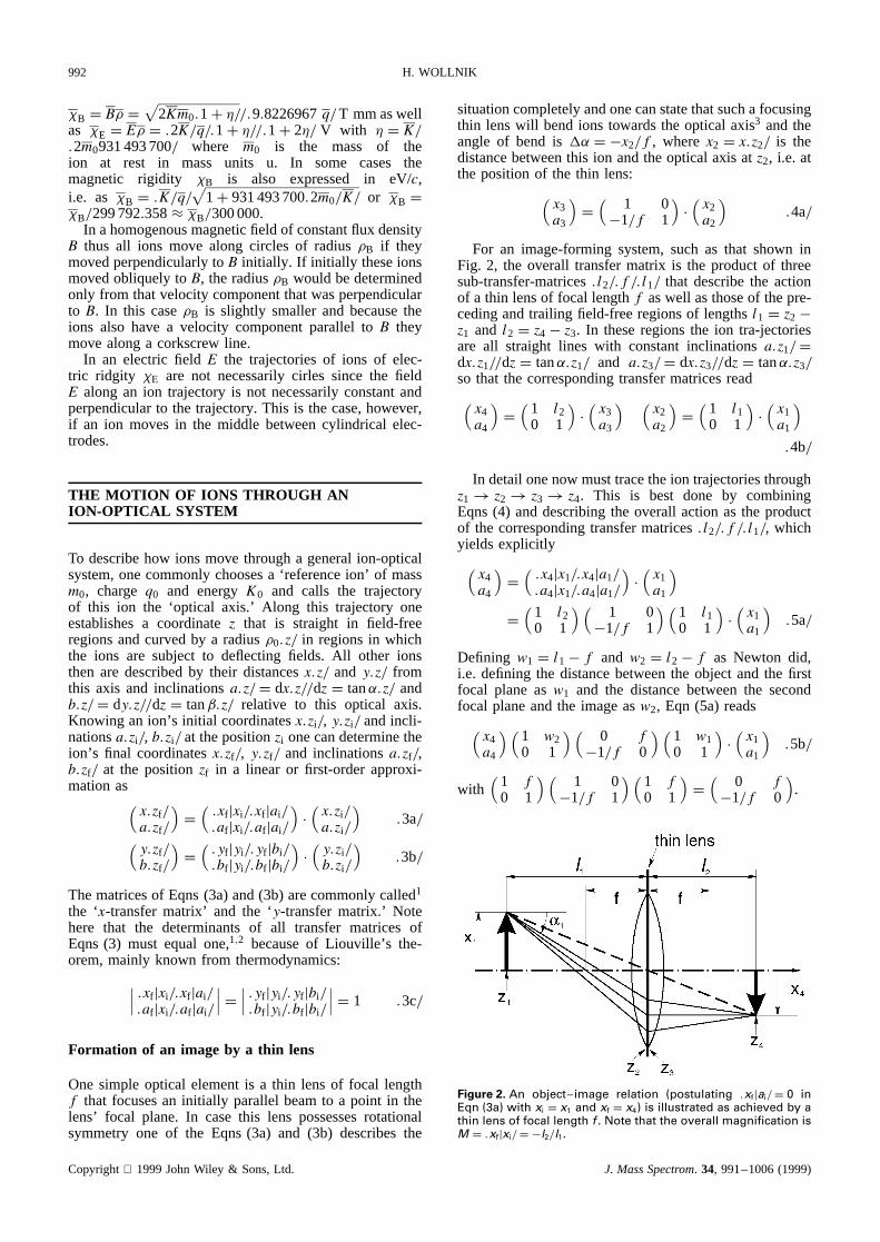
For an image-forming system, such as that shown inFig. 2, the overall transfer matrix is the product of threesub-transfer-matrices.l2/.f/.l1/ that describe the actionof a thin lens of focal lengthf as well as those of the pre-ceding and trailing field-free regions of lengthsl1 D z2 �z1 and l2 D z4 � z3. In these regions the ion tra-jectoriesare all straight lines with constant inclinationsa.z1/ Ddx.z1//dz D tan˛.z1/ and a.z3/ D dx.z3//dz D tan˛.z3/so that the corresponding transfer matrices read(x4a4
)D(
1 l20 1
)Ð(x3a3
) (x2a2
)D(
1 l10 1
)Ð(x1a1
).4b/
In detail one now must trace the ion trajectories throughz1! z2! z3! z4. This is best done by combiningEqns (4) and describing the overall action as the productof the corresponding transfer matrices.l2/.f/.l1/, whichyields explicitly(x4a4
)D(.x4jx1/.x4ja1/.a4jx1/.a4ja1/
)Ð(x1a1
)D(
1 l20 1
)(1 0�1/f 1
)(1 l10 1
)Ð(x1a1
).5a/
Defining w1 D l1� f and w2 D l2� f as Newton did,i.e. defining the distance between the object and the firstfocal plane asw1 and the distance between the secondfocal plane and the image asw2, Eqn (5a) reads(
x4a4
)(1 w20 1
)( 0 f�1/f 0
)( 1 w10 1
)Ð(x1a1
).5b/
with(
1 f0 1
)(1 0�1/f 1
)(1 f0 1
)D(
0 f�1/f 0
).
Figure 2. An object image relation (postulating .xfjai/ D 0 inEqn (3a) with xi D x1 and xf D x4) is illustrated as achieved by athin lens of focal length f . Note that the overall magnification isM D .xfjxi/ D �l2/l1.
Copyright 1999JohnWiley & Sons,Ltd. J. MassSpectrom. 34, 991–1006(1999)
ION OPTICS IN MASS SPECTROMETERS 993
Postulating an object–image relation between the posi-tions z1 andz4 in Eqn (5a), i.e. postulating that all trajec-tories that leave one pointx1 D x.z1/ are refocused to onepointx4 D x.z4/, one must require that the magnitude ofx4does not depend ona1 and that consequently.x4ja1/ D 0.After multiplying the transfer matrices of Eqn (5a) or (5b),this condition leads to the well known ‘lens equation:’3
1/l1C 1/l2 D 1/f or w1w2 D f2 .5c/
and the overall lateral magnificationM D .x4jx1/ D�l2/l1 D �w2/f.
When dealing with a ‘real lens’ that has some thicknessto it, one advantageously uses Eqn (5b) since this relationdescribes all lens effects correctly, even in complex cases,whereas Eqn (5a) only provides an approximate solution.The reason for this difference is that the distance betweenthe two focal planes of a real lens is usually slightly largerthan 2f.
An Einzel lens
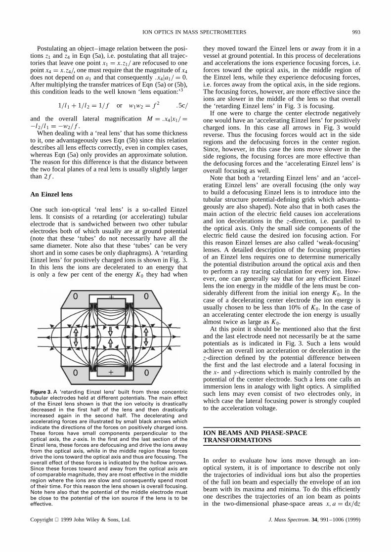
One such ion-optical ‘real lens’ is a so-called Einzellens. It consists of a retarding (or accelerating) tubularelectrode that is sandwiched between two other tubularelectrodes both of which usually are at ground potential(note that these ‘tubes’ do not necessarily have all thesame diameter. Note also that these ‘tubes’ can be veryshort and in some cases be only diaphragms). A ‘retardingEinzel lens’ for positively charged ions is shown in Fig. 3.In this lens the ions are decelerated to an energy thatis only a few per cent of the energyK0 they had when
Figure 3. A ‘retarding Einzel lens’ built from three concentrictubular electrodes held at different potentials. The main effectof the Einzel lens shown is that the ion velocity is drasticallydecreased in the first half of the lens and then drasticallyincreased again in the second half. The decelerating andaccelerating forces are illustrated by small black arrows whichindicate the directions of the forces on positively charged ions.These forces have small components perpendicular to theoptical axis, the z-axis. In the first and the last section of theEinzel lens, these forces are defocusing and drive the ions awayfrom the optical axis, while in the middle region these forcesdrive the ions toward the optical axis and thus are focusing. Theoverall effect of these forces is indicated by the hollow arrows.Since these forces toward and away from the optical axis areof comparable magnitude, they are most effective in the middleregion where the ions are slow and consequently spend mostof their time. For this reason the lens shown is overall focusing.Note here also that the potential of the middle electrode mustbe close to the potential of the ion source if the lens is to beeffective.
they movedtoward the Einzel lens or away from it in avesselat groundpotential.In this processof decelerationsandaccelerationsthe ions experiencefocusingforces,i.e.forces toward the optical axis, in the middle region ofthe Einzel lens,while they experiencedefocusingforces,i.e. forcesawayfrom the optical axis, in the sideregions.Thefocusingforces,however,aremoreeffectivesincetheions are slower in the middle of the lens so that overallthe ‘retardingEinzel lens’ in Fig. 3 is focusing.
If one were to charge the centerelectrodenegativelyonewouldhavean‘acceleratingEinzellens’ for positivelycharged ions. In this case all arrows in Fig. 3 wouldreverse.Thus the focusing forces would act in the sideregionsand the defocusingforces in the center region.Since,however,in this casethe ions moveslower in theside regions,the focusingforcesare more effective thanthedefocusingforcesandthe ‘acceleratingEinzel lens’ isoverall focusingaswell.
Note that both a ‘retardingEinzel lens’ andan ‘accel-erating Einzel lens’ are overall focusing (the only wayto build a defocusingEinzel lens is to introduceinto thetubular structurepotential-defininggrids which advanta-geouslyarealsoshaped).Note alsothat in both casesthemain action of the electric field causesion accelerationsand ion decelerationsin the z-direction, i.e. parallel tothe optical axis. Only the small side componentsof theelectric field causethe desiredion focusing action. Forthis reasonEinzel lensesare also called ‘weak-focusing’lenses.A detaileddescriptionof the focusingpropertiesof an Einzel lens requiresone to determinenumericallythe potentialdistributionaroundthe optical axis andthento performa ray tracing calculationfor every ion. How-ever, one can generallysay that for any efficient Einzellensthe ion energy in themiddleof the lensmustbecon-siderablydifferent from the initial ion energy K0. In thecaseof a deceleratingcenterelectrodethe ion energy isusuallychosento be lessthan10% of K0. In the caseofan acceleratingcenterelectrodethe ion energy is usuallyalmosttwice aslarge asK0.
At this point it shouldbe mentionedalso that the firstandthe last electrodeneednot necessarilybe at the samepotentialsas is indicated in Fig. 3. Such a lens wouldachievean overall ion accelerationor decelerationin thez-direction defined by the potential differencebetweenthe first and the last electrodeand a lateral focusing inthe x- andy-directionswhich is mainly controlledby thepotentialof the centerelectrode.Sucha lensonecalls animmersionlensin analogywith light optics.A simplifiedsuch lens may even consist of two electrodesonly, inwhich casethe lateralfocusingpoweris stronglycoupledto the accelerationvoltage.
ION BEAMS AND PHASE-SPACETRANSFORMATIONS
In order to evaluatehow ions move through an ion-optical system,it is of importanceto describenot onlythe trajectoriesof individual ions but also the propertiesof the full ion beamandespeciallytheenvelopeof an ionbeamwith its maximaandminima. To do this efficientlyone describesthe trajectoriesof an ion beamas pointsin the two-dimensionalphase-spaceareasx, a D dx/dz
Copyright 1999JohnWiley & Sons,Ltd. J. MassSpectrom. 34, 991–1006(1999)

994 H. WOLLNIK
and y, b D dy/dz. Here it is important to note that thephase-space areas filled by the trajectories of an ion beamcan change their shapes but not their areas1,2 because ofLiouville’s theorem. This constancy of phase-space areasalso is the reason that the determinants of transfer matricesall equal one [see Eqn (3c)].
An ion beam formed by a dipole sheet
Assume that a flat surface of width 2x00 emits ions ofmassm and chargeq that initially move in all directionswith low velocities vi or corresponding small energiesKi D mv2
i /2 with usuallyKi < 1 eV. If these ions are tobe accelerated in thez-direction, it is necessary, in gen-eral, to perform lengthy numerical calculations involvingthe solution of LaPlace’s equation for the given electrodeconfiguration and a detailed ray tracing for all ions underconsideration. In a usually fairly accurate approximation,however, one can describe the same situation by assum-ing that the acceleration occurs only in thez-direction andonly over a short distance, i.e. that a ‘dipole sheet’ accel-erates low-energy ions to a velocityv0 or a correspondingenergyK0. Such a dipole sheet can only increase thez-component of the ion velocity but leaves the perpendicularx- andy-components untouched. In thexz-plane the ionswill thus be inclined relative to thez-axis by
a0 D tan˛0 D vxi/v0 �√Ki/K0 .6/
This inclination is largest for those ions that initially moveperpendicularly to thez-axis, i.e. which are characterizedby vxi D vi and vzi D 0. Figure 4 shows such ion trajec-tories that originate fromx0 D šx00 under inclinationsa0 D ša00. These trajectories are also shown as pointsin the x, a phase-space plot characterizing a phase-spacerectangle of area 4x00a00, a quantity which often is abbre-viated to 4εx.
Since in real systems the corners of the phase-spacerectangle of Fig. 4 are usually poorly illuminated, oneoften assumes that the phase-space ellipse, that is inscribedin the phase-space rectangle, describes the full beam. Thisphase-space ellipse is upright and described by
.x0/x00/2C .a0/a00/
2 D 1 .7/
Figure 4. Trajectories for ions are shown that leave an area ofwidth 2x00 such that each point jx0j � jx00j of this area seemsto emit ions under the same maximal inclinations ja0j � ja00j.The corresponding phase-space area is 4x00a00. Note also thatone often uses only that part of the ion beam that is formed bytrajectories within the ellipse of phase-space area �x00a00.
An ion beam formed by an ion source and a pupil
In contrastto the situationin Fig. 4, onemay assumeanion sourcethatemitsionsunderlargeanglesof inclinationwhile the optical system acceptsonly those that passthroughananglelimiting ‘pupil.’ This pupil is anapertureof diameter2dx placeda distancelx downstreamfrom thesource.At the position of the object, i.e. at z D z1, thision beamoccupiesa parallelogram-likephase-spaceareashownin Fig. 5. Note,however,that for all mathematicalcalculationsit is sufficient to tracethepositionsof thefourcornersof theparallelogramcharacterizedinitially by x10,ša10� x10/lx and�x10, ša10C x10/lx. As analternativeone may1 assumea ‘virtual’ phase-spacerectangle(seeFig. 4) whosecornersšx00,ša00 transforminto the‘real’phase-spaceparallelogramshownin Fig. 5 by(
x1a1
)D( 1 0�1/lx 1
)Ð(šx00ša00
).8/
Note that the transfermatrix of Eqn (8) becomesa unitymatrix for lx D 1. Thus,a pupil that is placedat infinitydescribesan ion beamthat is characterizedby an uprightphase-spacerectangleor inscribedellipse(seeFig. 4).
Phase-spacetransformations thr ough an opticalsystem
On sendingions throughsomeopticalsystem,the ion tra-jectorieswill changetheir inclinationsandtheir distancesfrom theopticalaxisasfunctionsof z. Thecorrespondingphase-spacepointswill thusmovein thex, a phase-spacesuchthat the initial phase-spaceparallelogramof Fig. 5 istransformedinto z-dependentparallelogramswhosecor-ners mark the beam envelopefor each z-position (seeFig. 6). As a consequenceof Liouville’s theorem,mainlyknown from thermodynamics,all these parallelogramshave the samearea 4εx D 4x00a00 as the initial phase-spaceparallelogram.Along with the transformationsofthephase-spaceparallelogramsalsotheellipses,inscribedto the parallelograms,will transform with z all havingthe samearea�εx D �x00a00. Note also that this con-stancyof the phase-spaceareafor a given ion beamisthe reasonwhy the determinantsof all transfermatrices[seeEqn (3c)] areunity.1,2
Most generallyphase-spaceellipsesaredescribedby asecond-orderrelationin x.z/ andin a.z/ as
x.z/2 C [x.z/˛T.z/C a.z/ˇT.z/]2
D ˇT.z/x10a10 D ˇT.z/x00a00 D ˇT.z/εx .9a/
Figure 5. Trajectories of ions that leave an area of width 2x00
under different angles as long as these trajectories pass throughthe pupil shown of width 2dx placed a distance lx downstreamfrom the object.
Copyright 1999JohnWiley & Sons,Ltd. J. MassSpectrom. 34, 991–1006(1999)

ION OPTICS IN MASS SPECTROMETERS 995
Figure 6. Phase-space transformations are shown for a beam that passes through a thin lens focusing system. Shown are trajectoriesthat leave from an object of size 2x10 and pass through a pupil of size 2dx. Note the phase-space parallelograms of equal areas and theinscribed phase-space ellipses. Note also the corresponding beam envelopes which are smooth for a beam of elliptical phase-spaceareas and piecewise straight lines for a beam of parallelogram-like phase-space areas. Note further that object and image are locatedat z1, z6 and beam waists at z2, z7.
where the so called ‘Twiss parameters’ T.z/ and ˇT.z/vary with z.1,4 Determining dx/da D 0 for this generalellipseequation,onefinds for everyz-position the maxi-mum valueof x.z/, i.e. the sizeof the beamenvelope,as
xmax.z/ D√ˇT.z/x00a00 D
√ˇT.z/εx .9b/
Note that Eqn (9a) transformsto Eqn (7) for ˛T D 0, theequationfor an upright phase-spaceellipse (seeFig. 4).Such an upright phase-spaceellipse is characterizedby˛T D 0 andˇT D x00/a00.
Knowing the transfer matrix that describesthe finalx.z/, a.z/ of any one of the ion trajectoriesthat startedfrom oneof the four cornersof the initial upright phase-spacerectangle,i.e. fromšx00ša00, onecandetermine1,4
the parameters T.z/, ˇT.z/ of the correspondingphase-spaceellipseas(x.z/a.z/
)D(.xjx/.xja/.ajx/.aja/
)Ð(šx00ša00
).10a/(
ˇT.z/˛T.z/
)D(
.xjx/2 .xja/2.xjx/.ajx/ .xja/.aja/
)Ð(x00/a00a00/x00
).10b/
Determining ˇT.z/ from Eqn (10b) and introducing itinto Eqn (9b), one finds the beamenvelopefor every z-positionas
xmax.z/ D√.xjx/2x2
00C .xja/2a200 .11/
Note that the envelopexmax.z/ for a beamof ellipticalphase-spacearea changessmoothly along z, exhibitingmaximaand minima (seeFig. 6) which are called beamwaists1,4 at which z-positions˛T vanishes.Note alsothat
in Eqns(10)and(11)no indicesof thez-dependentmatrixelementsare given since the meaningof theseelementsseemsself-explanatory.
The mentionedphase-spacetransformationsof an ionbeamthroughan ion-opticalsystemcanbe illustratedbytracing the ion trajectoriesin a thin-lensimaging systemas shown in Fig. 6. In this figure one seesthe ‘uprightparallelograms’for the object at x1 D x.z1/ and for theimage at x6 D x.z6/, i.e. z-positions at which the sametwo parallelogramsides are upright. One also seestheinscribedupright ellipses (˛T D 0) at x2 D x.z2/ and atx7 D x.z7/, i.e. at the first andthe secondbeamwaists.
ION BEAMS MOVING THROUGH QUADRUPOLELENSES OR SECTOR FIELDS
A quadrupole lens
An often usedion lens is a quadrupoleof lengthw andaperture2G. Such a lens consistof four hyperbolicallyshapedelectrodesor correspondinglyshapedmagnetpoles(see Fig. 7). In both casesthe hyperbolic surfacesareoften approximatedby cylindrically shapedones sincethoseareeasierto fabricate.Although good resultshavebeenobtainedby choosingthe cylinder diametersto be2Rr ³ 2G, one finds even better results by choosing5
thesediametersto be 2Rr ³ 1.1468ð 2G. The reasonisthat for the 2G casethe hyperbolasstill are a slightlywider azimuthally than the cylinders of diameter 2G,
Copyright 1999JohnWiley & Sons,Ltd. J. MassSpectrom. 34, 991–1006(1999)
996 H. WOLLNIK
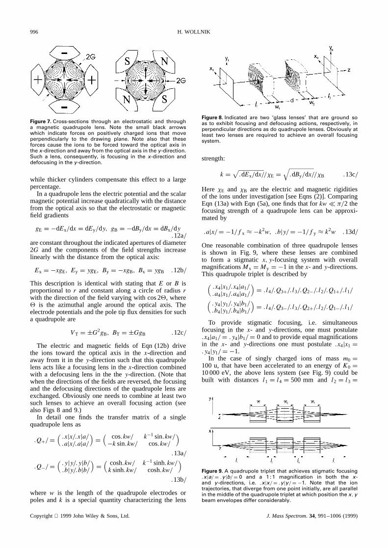
Figure 7. Cross-sections through an electrostatic and througha magnetic quadrupole lens. Note the small black arrowswhich indicate forces on positively charged ions that moveperpendicularly to the drawing plane. Note also that theseforces cause the ions to be forced toward the optical axis inthe x-direction and away from the optical axis in the y-direction.Such a lens, consequently, is focusing in the x-direction anddefocusing in the y-direction.
while thicker cylinderscompensatethis effect to a largepercentage.
In a quadrupolelenstheelectricpotentialandthescalarmagneticpotentialincreasequadraticallywith thedistancefrom the optical axis so that the electrostaticor magneticfield gradients
gE D �dEx/dx D dEy/dy, gB D �dBy/dx D dBx/dy.12a/
areconstantthroughouttheindicatedaperturesof diameter2G and the componentsof the field strengthsincreaselinearly with the distancefrom the optical axis:
Ex D �xgE, Ey D ygE, By D �xgB, Bx D ygB .12b/
This descriptionis identical with stating that E or B isproportionalto r and constantalong a circle of radiusrwith thedirectionof thefield varyingwith cos2, where is the azimuthal angle around the optical axis. Theelectrodepotentialsandthepoletip flux densitiesfor sucha quadrupoleare
VT D šG2gB, BT D šGgB .12c/
The electric and magnetic fields of Eqn (12b) drivethe ions toward the optical axis in the x-direction andawayfrom it in the y-directionsuchthat this quadrupolelensactslike a focusinglensin the x-directioncombinedwith a defocusinglens in the the y-direction. (Note thatwhenthedirectionsof thefieldsarereversed,thefocusingand the defocusingdirectionsof the quadrupolelens areexchanged.Obviouslyoneneedsto combineat leasttwosuch lensesto achievean overall focusing action (seealsoFigs 8 and9.)
In detail one finds the transfer matrix of a singlequadrupolelensas
.QC/ D(.xjx/.xja/.ajx/.aja/
)D(
cos.kw/ k�1 sin.kw/�k sin.kw/ cos.kw/
).13a/
.Q�/ D(.yjy/.yjb/.bjy/.bjb/
)D(
cosh.kw/ k�1 sinh.kw/k sinh.kw/ cosh.kw/
).13b/
where w is the length of the quadrupoleelectrodesorpolesand k is a specialquantity characterizingthe lens
Figure 8. Indicated are two ‘glass lenses’ that are ground soas to exhibit focusing and defocusing actions, respectively, inperpendicular directions as do quadrupole lenses. Obviously atleast two lenses are required to achieve an overall focusingsystem.
strength:
k D√.dEx/dx//�E D
√.dBy/dx//�B .13c/
Here �E and �B are the electric and magneticrigiditiesof the ionsunderinvestigation[seeEqns(2)]. ComparingEqn (13a)with Eqn (5a),onefindsthat for kw− �/2 thefocusing strengthof a quadrupolelens can be approxi-matedby
.ajx/ D �1/fx ³ �k2w, .bjy/ D �1/fy ³ k2w .13d/
One reasonablecombinationof three quadrupolelensesis shown in Fig. 9, where these lensesare combinedto form a stigmatic x, y-focusing system with overallmagnificationsMx D My D �1 in thex- andy-directions.This quadrupoletriplet is describedby(
.x4jx1/.x4ja1/
.a4jx1/.a4ja1/
)D .l4/.Q3C/.l3/.Q2�/.l2/.Q1C/.l1/(
.y4jy1/.y4jb1/
.b4jy1/.b4jb1/
)D .l4/.Q3�/.l3/.Q2C/.l2/.Q1�/.l1/
To provide stigmatic focusing, i.e. simultaneousfocusing in the x- and y-directions,one must postulate.x4ja1/ D .y4jb1/ D 0 andto provideequalmagnificationsin the x- and y-directions one must postulate.x4jx1 D.y4jy1/ D �1.
In the case of singly charged ions of mass m0 D100 u, that havebeenacceleratedto an energy of K0 D10000 eV, the abovelens system(seeFig. 9) could bebuilt with distancesl1 D l4 D 500 mm and l2 D l3 D
Figure 9. A quadrupole triplet that achieves stigmatic focusing.xja/ D .y jb/ D 0 and a 1 : 1 magnification in both the x-and y-directions, i.e. .xjx/ D .y jy/ D �1. Note that the iontrajectories, that diverge from one point initially, are all parallelin the middle of the quadrupole triplet at which position the x,ybeam envelopes differ considerably.
Copyright 1999JohnWiley & Sons,Ltd. J. MassSpectrom. 34, 991–1006(1999)

ION OPTICS IN MASS SPECTROMETERS 997
100 mm and quadrupoles of lengthw1 D w2 D w3 D300 mm with electrostatic or magnetic field gradients:
dEx1/dx D dEx3/dx D �0.09831 V mm�2
dEx2/dx D 0.11366 V mm�2
dBy1/dx D dBy3/dx D �0.001406 T mm�1
dBy2/dx D 0.001628 T mm�
Note that for a quadrupole of 2G ³ 2ð 20 mm aperture,the corresponding electrode potentials would be�39.3 Vand 45.5 V and the corresponding pole tip flux densitieswould be�0.028 T and 0.0325 T. All these fields arerelatively small since the focusing actions in quadrupolelenses are caused by the main field. For this reasonquadrupole lenses are also called ‘strong-focusing’ lenses.
A more complex quadrupole arrangement, a trans-port channel, is illustrated in Fig. 10, in which casean ion beam, that fills an elliptical phase-space area,passes through a multitude of focusing and defocusingquadrupole lenses. Note that the beam envelope has min-ima in the x-direction whenever it has maxima in they-direction and vice versa.
In the example shown all beam waists were chosen tobe of equal sizes, which allows a channel as shown inFig. 10. Such a channel is useful for a ring acceleratoror for a storage ring. For special cases of limited lengtheach beam waist can also be a certain percentage smallerthan the preceding one.6 This would cause the angles ofinclination of the ion trajectories to increase because ofthe constancy of a phase-space area unless it is possible toreduce the energy spread of the ions and thus the phase-space filled by the ion beam.6
A space-charge lens
In a beam of ions of total currentI and round cross-section�rb2, the individual ions experience repulsing Coulombforces. These forces cause an initially almost parallelbeam to become increasingly divergent (see Fig. 11).Assuming a constant current densityI/�rb2 across thisbeam of diameter 2rb, which usually is only approximatelyachieved, one calculates a radial electric field at a givendistancer from the optical axis as
Er D r
2ε0Ð I
rb2�v.14/
Figure 10. A quadrupole transport channel in which the phase-space areas of the ion beam and the geometry of thequadrupoles are matched. Note the positions of beam maximaand minima in the x- and y-directions as well as their relativesizes.
Figure 11. In intense beams of ions the individual ions expe-rience repulsive forces which cause the corresponding iontrajectories to become divergent. This action can be described bya potential depression V that has the same diverging effect onthe ion trajectories as the individual repelling forces. Note herethatV is independent of the diameter 2rb of the ion beam whichcauses the radial field strength Er and thus the space-chargeforces to become strongest at narrow beam cross-sections.
where ε0 ³ 8.85ð 10�12 A s V�1 m�1 is the dielectricconstant.Integrating over this field strengthEr from 0to rb onefinds a total potentialdepressionacrossthe ionbeam(seeFig. 11) of:
V D I/.4�ε0v/ or numerically V ³ I/v .15/
in V if thebeamcurrentI is in µA andtheion velocityv inmm µs�1. NotethatV is independentof thebeamdiam-eter2rb. Theelectricfield consequentlyis Er D 2Vr/r2
b,i.e. Er increasesquadraticallywith decreasingrb. Thisfield drives all ions away from the optical axis simi-larly to a rotationallysymmetricweakbut long defocusinglens of focal strength1/f D k sin.kw/ ³ k2w. Thus onefinds with k2 D .dEr/dr//�E D V/rb2K0 accordingtoEqn (13d)
rbf³ w
rbÐ VK0
.16/
Note that the defocusingspace-charge forces are pro-portional to 1/f, which itself is proportional to 1/rb.Focusinga bundle of ions of given ion energy K0 andbeam current I to smaller beam diametersthus causeslarger space-charge forceswhile the potentialdepressionV staysthe same.
Looking at the examplein Fig. 9 andassumingthat toa very roughapproximationthebeamof massm D 100 uionsof K0 D 10000 eV hasadiameter2rb D 20 mmfor atotal lengthw D 1500mm andthat,accordingto Eqn (1),the ions have a velocity v ³ 100 mm µs�1, one findsfrom Eqns(15) and (16) that for I D 1 µA the poten-tial depressionis V ³ 0.09 V and that f ³ 726 mm.This focal length is comparableto the focal length ofthe quadrupoletriplet of Fig. 9. Thus,by experimentallyreadjustingthe field gradientsin this quadrupoletripletby small percentages,one can still achievethe desiredstigmaticbeamfocusing.For a 10-fold larger beamcur-rent,i.e. for I D 10 µA, however,this would no longerbepossible.
Since the electric field Er is inverselyproportionaltothe beamdiameter2rb along an ion beam,the action ofspace-charge forcesbecomesstrongestat thosepositionsat which the currentdensityis highest.For this reasonitusually is helpful to not produceone stigmatic focus inthex- andin they-directionbut ratherseethatthex-focusoccursat a differentz-position thanthe y-focus.
Note also that the ion’s spacecharge trapslow-energyparticlesof oppositecharge.Thechargeof theseparticles
Copyright 1999JohnWiley & Sons,Ltd. J. MassSpectrom. 34, 991–1006(1999)
998 H. WOLLNIK
then partially compensates the potential depressionVof the space charge of the ion beam. Note, however, thatthese low-energy particles can move freely along the ionbeam, as they could in a plasma. Thus they are easilypulled to any electrode that is at an attractive potentialsuch as the ion source. In applications in which intense ionbeams are necessary, one therefore usually accelerates theions from the ion source by an accelerating–deceleratingelectrode arrangement by which the desired ions arefirst accelerated to a potential below ground and thendecelerated to ground. Thus for a beam of positivelycharged ions, low-energy electrons or negatively chargedions cannot be sucked into the ion source.
Laterally dispersive mass analyzers
A homogeneous magnetic sector field.If a reference ion ofmass-to-charge ratiom0/q0 and energy-to-charge ratioK0/q0 moves in a homogeneous magnetic flux densityB0 along a circle�0, one finds that an arbitrary ion ofmass-to-charge ratiom/q D .m0/q0/.1C υm/ and energy-to-charge ratioK/q D .K0/q0/.1C υK/ moves along aradius
� D �0.1C/ ³ �0.1C υm/2C υK/2C Ð Ð Ð/ .17/
This relation one finds from a power series expansion ofthe momentum-to-charge rigidity�B D B0� D
p2Km/q
of Eqn (2c) aroundK0/q0 andm0/q0:
�B0.1C/ D√
2.K0/q0/.1C υK/.m0/q0/.1C υm/³√
2.K0/q0/.m0/q0/ð .1C .υKC υm//2C Ð Ð Ð/.
If such an ion had entered the magnetic field at a distancex1 D x.z1/ from the optical axis of radius�0 and under aninclination a1 D dx.z1//dx D a.z1/ relative to the opticalaxis, one finds the corresponding coordinatesx2, a2 at themagnet exit from simple geometry as1
(x2a2
)D(
cos �0 sin �0.1� cos/��0
�1 sin cos sin0 0 1
)
Ð(x1a1
).18/
Here the optical axis of radius�0 is bent by an angle0.For a complete momentum analyzer (see Fig. 12) in whichfield-free regions of lengthl1 and l2 precede and followthe sector field, one finds withc D cos0 ands D sin0(
x4a4
)D(.xjx/ .xja/ .xj/.ajx/ .aja/ .aj/
0 0 1
)Ð(x1a1
)
D(
1 l2 00 1 00 0 1
)(c �0s �0.1� c/�s/�0 c s
0 0 1
)
ð(
1 l1 00 1 00 0 1
)Ð(x1a1
).19a/
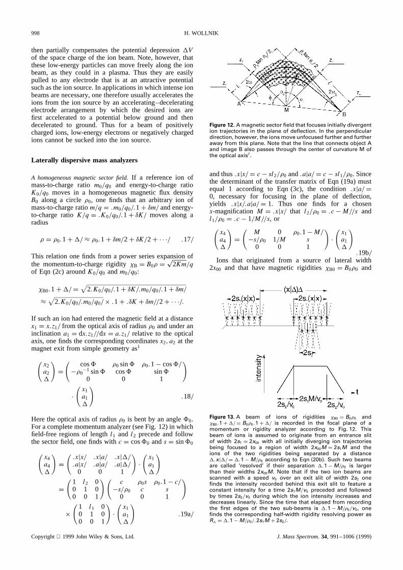
Figure 12. A magnetic sector field that focuses initially divergention trajectories in the plane of deflection. In the perpendiculardirection, however, the ions move unfocused further and furtheraway from this plane. Note that the line that connects object Aand image B also passes through the center of curvature M ofthe optical axis7.
andthus.xjx/ D c� sl2/�0 and.aja/ D c� sl1/�0. Sincethe determinantof the transfermatrix of Eqn (19a)mustequal 1 according to Eqn (3c), the condition .xja/ D0, necessaryfor focusing in the plane of deflection,yields .xjx/.aja/ D 1. Thus one finds for a chosenx-magnificationM D .xjx/ that l2/�0 D .c �M//s andl1/�0 D .c� 1/M//s, or(
x4a4
)D(
M 0 �0.1�M/�s/�0 1/M s
0 0 1
)Ð(x1a1
).19b/
Ions that originated from a source of lateral width2x00 and that have magneticrigidities �B0 D B0�0 and
Figure 13. A beam of ions of rigidities �B0 D B0�0 and�B0.1C/ D B0�0.1C/ is recorded in the focal plane of amomentum or rigidity analyzer according to Fig. 12. Thisbeam of ions is assumed to originate from an entrance slitof width 2s1 D 2x00 with all initially diverging ion trajectoriesbeing focused to a region of width 2x00M D 2s1M and theions of the two rigidities being separated by a distance.xj/ D .1�M/�0 according to Eqn (20b). Such two beamsare called ‘resolved’ if their separation .1�M/�0 is largerthan their widths 2x00M. Note that if the two ion beams arescanned with a speed v0 over an exit slit of width 2s2 onefinds the intensity recorded behind this exit slit to feature aconstant intensity for a time 2s1M/v0 preceded and followedby times 2s2/v0 during which the ion intensity increases anddecreases linearly. Since the time that elapsed from recordingthe first edges of the two sub-beams is .1�M/�0/v0, onefinds the corresponding half-width rigidity resolving power asR D .1�M/�0/.2s1M C 2s2/.
Copyright 1999JohnWiley & Sons,Ltd. J. MassSpectrom. 34, 991–1006(1999)

ION OPTICS IN MASS SPECTROMETERS 999
�B D B� D B0�0.1C/, one finds to be separated inthe end, i.e. in the focal plane of the sector magnet, by.xj/ D �0.1�M/. Thus one says that the systempossesses
a rigidity dispersion
DB D .xj/ D �0.1�M/ .20a/
a mass-to-charge dispersion
DBm D .xjm/υm D �0.1�M//2υm .20b/
an energy-to-charge dispersion
DBK D .xjK/υK D �0.1�M//2υK .20c/
Since the final image has a width 2x00.xjx/ D 2x00M,one finds the minimal resolvablemin from .xj/min D.xjx/2x00 (see Fig. 13). The inverse of thismin is calledthe rigidity or momentum resolving power of a magneticsector field,RB:
RB D 1/min D .xj//[.xjx/2x00]
D .1/M� 1/�0/.2x00/ .21a/
Analogously, one finds a corresponding energy-to-chargeand mass-to-charge resolving power [see Eqns (20)]:
RBK D 1/υKmin D .xjK//[.xjx/2x00]
D .1/M� 1/�0/.4x00/ D RB/2 .21b/
RBm D 1/υmmin D .xjm//[.xjx/2x00]
D .1/M� 1/�0/.4x00/ D RB/2 .21c/
A magnetic sector field with inclined field boundaries.In somesector magnets the ions enter and leave the sector fieldobliquely as is indicated in Fig. 14. Although the opticalaxis is identical with that in Fig. 12, one here has entranceand exit anglesε1 and ε2, which are called positive forthe case when the ions that enter the sector field further
Figure 14. If ions cross the field boundaries of a magnetic sectorfield obliquely, they experience a focusing action in the directionperpendicular to the plane of deflection combined with a reducedfocusing power in the plane of deflection.1,8 Thus overall for theplane of deflection the object and image distances are longerthan for the case in Fig. 12. Note that for negative values of ε1
and ε2, these object and image distances are shorter than for thecase in Fig. 12 and the ions are defocused in the perpendiculardirection.
awayfrom thecenterof curvature.M/ will crossthefieldboundarylaterthantheywouldhavein thecasein Fig. 12.From a detailedanalysis,1 one finds that positive ε1 andε2 causea reductionin the focusingpower in the planeof deflectionand thus larger object and imagedistancesl1 andl2. However,positiveε1 andε2 alsocauseall ionsthat are oblique to the planeof deflectionto be focusedback to this plane.1,8 In detail one finds overall transfermatricesfor the xz- and yz-planesof this systemwitht1 D �0
�1 tanε1 and t2 D �0�1 tanε2:(
xfaf
)D(.xjx/ .xja/ .xj/.ajx/ .aja/ .aj/
0 0 1
)
D(
1 l2 00 1 00 0 1
)(1 0 0�t2 1 00 0 1
)
ð(
c �0s �0.1� c/�s/�0 c s
0 0 1
)(1 0 0�t1 1 00 0 1
)
ð(
1 l1 00 1 00 0 1
)Ð(x0a0
).22a/
(yfbf
)D(.yjy/.yjb/.bjy/.bjb/
)D(
1 l20 1
)(1 0t2 1
)(1�0 00 1
)ð( 1 0t1 1
)( 1 l10 1
)Ð(y0b0
).22b/
For a sector field analyzeras shown in Fig. 14 oneusuallypostulatesa stigmaticfocus,i.e. a focusin the x-andin the y-direction,or .xja/ D .yjb/ D 0. For a sectorfield of a deflectionangle0 D 1 C2 onethusfinds1
2�0/l1 D tan1 D 2tanε2
.xjx/ D Mx D � sin1/ sin2 .23a/
2�0/l2 D tan2 D 2tanε2
.yjy/ D My D � tan1/ tan2. .23b/
Furthermore,onefinds the rigidity dispersionas.xj/ D2�0.1�M/ andthe rigidity resolvingpoweras
R D 1/min D .xj//[.xjx/2x00] D �0.1/M� 1//x00..23c/
Note that the rigidity dispersion.xj/ and the rigidityresolvingpowerR D 1/min in Eqn (22c) are twice aslargeasthecorrespondingquantitiesin Eqns(20)and(21)that describedthe propertiesof a homogeneousmagneticsectorfield with ion beamsthatenterandleavethesectorfield perpendicularly.
An angle-and energy-focusingmassspectrometer.So far onlythe momentum-to-charge or rigidity dispersionin a sec-tor field has been described explicitly in a transfermatrix. In general,however,it is of advantageto expressthe mass-to-charge andenergy-to-charge dispersions[seeEqns(20)] alreadyin the transfermatricesanduse4ð 4first-ordertransfermatricesfor systemsthatincludesectorfields.Suchtransfermatricesreadasfollows for theplaneof deflection: xi
aiυmυk
D M 0 Dm Dk�1/F 1/M D0m D0k
0 0 1 00 0 0 1
x0a0υmυk
.24/
Copyright 1999JohnWiley & Sons,Ltd. J. MassSpectrom. 34, 991–1006(1999)

1000 H. WOLLNIK
if the system is angle focusing.xja/ D 0, so thatx doesnot depend on 0.
For a system that includes a magnetic sector field andthat separates ions according to their magnetic rigiditiesp
2Km/q, one finds here analogously to Eqns (20)
DBm D DB/2 DBK D DB/2 .25a/
For a system that includes an electrostatic sector field andthat separates ions according to their electrostatic rigidities2K, one finds
DEm D 0 DEK D DE .25b/
Using a real ion source that produces ions of chargeq andmassm0.1C υm/ with some energy spreadšK, oneaccelerates these ions to an energyK0šK D K0.1šυK/. Thus the achievable mass-to-charge resolving powerwill always be limited by the energy-to-charge dispersionof the systemDKυK. This limitation can be avoided,however, if one uses two separation stages I and II whoseenergy dispersionsDIK andDIIK compensate each other.There are two principle solutions for this problem:
1. one can build a system as shown in Fig. 15 in whichthe first stage contains an electrostatic sector fieldand the second stage a magnetic sector field9 anddesign the system such that the overall energy-to-charge dispersionDKυK vanishes, i.e. the energy-to-charge dispersionDIKυK of the first stage com-pensates the energy-to-charge dispersionDIIK υK ofthe second stage. Since the electrostatic sector fielddoes not have a mass-to-charge dispersionDIm D 0,the mass-to-charge dispersionDIImυm of the secondstage, that contains the magnetic sector field, staysuntouched. In this case the overall energy-to-chargeand mass-to-charge dispersions are
.MIIDIK C DIIK /υK D 0 and DIImυm 6D 0
Figure 15. An angle- and energy-focusing mass spectrome-ter that consists of one electrostatic and one magnetic sec-tor field.9 The first stage has no mass-to-charge dispersionbut an energy-to-charge dispersion that exactly compen-sates the energy-to-charge dispersion of the second stage.The ion beam contains ions of two energy-to-charge ratios.K0/q0/.1C υK/, i.e. two υK values, and of three mass-to-chargeratios .m0/q0/.1C υm/, i.e. of three υm values. Hence there aretwo intermediate and three final images.
Theadvantageof suchanangle-andenergy-focusingmassspectrometer9,11 is that it is relatively inexpen-sive to build for not too high performancelevels.For high mass-to-charge resolving powersat hightransmissions,however, the requiredprecision forthe electrostaticanalyzercanbecomevery high.
2. onecanbuild asystemin whichbothstagesusemag-netic sectorfields anddesignthe systemsuch11 thatthe energy-to-chargedispersionDIIυK in the secondstageis n timeslargerthantheenergy-to-chargedis-persionDIυK in thefirst oneandthatfurthermorethetwo stagesareplacedat suchelectrostaticpotentialsthat for a given charge q the energy of the refer-enceion isKI in thefirst stageandKII D nKI in thesecond.This requiresthat the ions gain the energy.n� 1/KI betweenthetwo stagessothatanarbitraryion hasthe energies
in stageI: KI šK D KI.1š υK/in stageII: nKI šK D nKI.1š υK/n/
If sucha systemis arrangedsuchthat theenergy-to-charge dispersionDIKυK of the first stagecompen-satesthe energy-to-charge dispersionDIIK υK of thesecondstage,onefinds the overall energy-to-chargeandmass-to-charge dispersionsto be
DKυK D DII υK/n�MIIDIυK
D nDIυK/n�MIIDIυK D 0
Dmυm D DII υm �MIIDIυm
D nDIυm �MIIDIυm D .n�MII /DIυm
Thus, also if the ions have a large energy spreadšK such energy achromaticsystemscan have alarge mass-to-charge resolvingpower
Rm D Dmυm/.2x00MIMII /
Figure 16. An angle- and energy-focusing mass spectrometerthat consists of two magnetic sector fields between which theions are accelerated,11 here by a dipole sheet. Thus both stageshave mass-to-charge and energy-to-charge dispersions whichare dimensioned such that the energy-to-charge dispersions ofthe two stages compensate each other. Hence there are sixintermediate and three final images.
Copyright 1999JohnWiley & Sons,Ltd. J. MassSpectrom. 34, 991–1006(1999)
ION OPTICS IN MASS SPECTROMETERS 1001
As compared with the design of Aston,9 which featuresonly one mass-to-charge analysis, the author’s system11
can eliminate much better ions of neighboring mass-to-charge ratios that have been scattered on residual gasatoms or molecules and thus cause contamination of theions of interest. However, it requires the use of two usuallyexpensive magnetic sector fields.
Note that in both cases the achievable half-width mass-resolving power isDmυm/.2s1MIMII C 2s2/ with MI andMII being the lateral magnifications of the first- andsecond-stage sector fields and with 2s1 and 2s2 being thewidths of the entrance and exit slits of the double-focusingmass spectrometer. Note also that obviously both systemscan be reversed without changing the overall performanceof the system except for the overall lateral magnification.
IMAGE ABERRATIONS
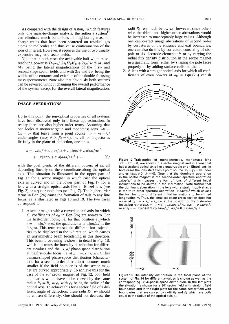
Up to this point, the ion-optical properties of all systemshave been discussed only in a linear approximation. Inreality there are also higher order terms. Assuming thatone looks at monoenergetic and monomass ions.υK Dυm D 0/ that leave from a point source.x0 D y0 D 0/under angles (š˛0 6D 0, ˇ0 D 0), i.e. all ion trajectorieslie fully in the plane of deflection, one finds
x D ..xja/C z.aja//a0 C ..xjaa/C z.ajaa//a02
C ..xjaaa/C z.ajaaa//a03C Ð Ð Ð .26/
with the coefficients of the different powers ofa0 alldepending linearly on thez-coordinate along the opticalaxis. This situation is illustrated in the upper part ofFig. 17 for a sector magnet in which case the opticalaxis is curved and in the lower part of Fig. 17 for alens with a straight optical axis like an Einzel lens (seeFig. 3) or a quadrupole lens (see Fig. 7). The higher orderterms in Eqn (26) cause the formation of tails to any linefocus, as is illustrated in Figs 18 and 19. The two casescorrespond to
1. A sector magnet with a curved optical axis for whichall coefficients ofa0 in Eqn (26) are non-zero. Forthe first-order focus, i.e. for that position at whichz D �.xja//.aja/, the quadratic term.xjaa/a0
2 is thelargest. This term causes the different ion trajecto-ries to be displaced in thex-direction, which causesan unsymmetric beam broadening in this direction.This beam broadening is shown in detail in Fig. 18,which illustrates the intensity distribution for differ-ent x-values and the.x, a/ phase-space distributionat the first-order focus, i.e. atz D �.xja//.aja/. Thisbanana-shaped phase-space distribution (character-istic for a second-order aberration) becomes muchsmaller if the field boundaries of the sector mag-net are curved appropriately. To achieve this for thecase of the 90° sector magnet of Fig. 12, both fieldboundaries would have to be curved by the sameradiusR1 D R2 D �0 with �0 being the radius of theoptical axis. To achieve this for a sector field of a dif-ferent angle of deflection, these radiiR1, R2 shouldbe chosen differently. One should not decrease the
radii R1, R2 much below�0, however, since other-wise the third- and higher-order aberrations wouldbe increased to unacceptably large values. Althoughone can correct image aberrations of second orderby curvatures of the entrance and exit boundaries,one can also do this by correctors consisting of six-pole or six-electrode elements1,12 or by varying theradial flux density distribution in the sector magnetin a quadratic form1 either by shaping the pole facesproperly or by adding surface coils1 to them.
2. A lens with a straight optical axis for which all coef-ficients of even powers ofa0 in Eqn (26) vanish
Figure 17. Trajectories of monoenergetic, monomass ions.υK D υm D 0/ are shown in a sector magnet and in a lens thathas a straight optical axis like a quadrupole or an Einzel lens. Inboth cases the ions start from a point source .x0 D y0 D 0/ underangles (š˛0 6D 0, ˇ0 D 0). Note that the dominant aberrationin the sector magnet is the second-order aperture aberration.xjaa/a0
2 which causes the foci of ions of different initialinclinations to be shifted in the x-direction. Note further thatthe dominant aberration in the lens with a straight optical axisis the third-order aperture aberration .xjaaa/a0
3 which causesthe foci for ions of different initial inclinations to be shiftedlongitudinally. Thus, the smallest beam cross-section does notoccur at z4 D �.xja//.aja/, i.e. at the position of the first-orderfocus, but rather at z5 D �..xja/C .xjaaa/a0
2//..aja/C .ajaaa/a02/
or at z6 D �..xja/C 0.3.xjaaa/a02//..aja/C 0.3.ajaaa/a0
2/.
Figure 18. The intensity distribution in the focal plane of thesystem of Fig. 14 for different x-values is shown as well as thecorresponding .x,a/-phase-space distribution. In the left plotsthe situation is shown for a 90° sector field with straight fieldboundaries and in the right plots for the same sector field withboundaries that are curved by radii R1 and R2 which are bothequal to the radius of the optical axis �0.
Copyright 1999JohnWiley & Sons,Ltd. J. MassSpectrom. 34, 991–1006(1999)

1002 H. WOLLNIK
Figure 19. For a lens with a straight optical axis (see Figs 3 and 9)the intensity distribution for different x-values is shown as wellas the corresponding .x,a/ phase-space distribution. These dis-tributions are shown at three different z-positions along the opti-cal axis (see the lower part of Fig. 17), i.e. for z D �.xja//.aja/ andfor z D �..xja/C c.xjaaa/a0
2//..aja/C c.ajaaa/a02/ with c D 1.0
and also with c D 0.3.
becauseof symmetry,i.e. .xjaa/C z.ajaa/ D 0. Forthe first-order focus, i.e. for that position at whichz D �.xja//.aja/, the cubic term is the largest,i.e. ..xjaaa/C z.ajaaa//a0
3. Thesedifferent x-fociare longitudinally displacedwhich causessymmet-ric beam broadenings.This beam broadening isillustrated in the lower part of Fig. 19 display-ing the intensity distribution for different x-valuesand the .x, a/ phase-spacedistribution at the posi-tion of the first order focus at z D �.xja//.aja/ aswell asat thosez-positionsat which z D �..xja/Cc.xjaaa/a0
2//..aja/C c.ajaaa/a02/ with c D 1.0 or
0.3, respectively.To choosec D 0.3 is usually agood compromisebetweena reductionin the tailsof a line and in the line half-width. The x-widthof this S-shapedphase-spacedistribution (charac-teristic of a third-order aberration)can be reducedby employing an eight-pole or an eight-electrodecorrector.1,12 However,caremustbe takenthat thiscorrectionof a third-orderaberrationis achievedbymodestfield strengthsin thesecorrectorsso that thefifth-, seventh-andhigherorderaberrationsarenotincreasedappreciably.
ELECTRIC R.F. MULTIPOLES
Consider a long electric quadrupoleto the electrodesof which a high-frequencyvoltage of some MHz anda few hundredV is applied. Along the axis of such aquadrupoleone then may passions of energy-to-chargeratiosof a few eV. Theseionswill movealongtheopticalaxis of this quadrupoleof perhaps250 mm length withvelocitiesof about5.0–0.5 mm µs�1 if they havemassesof 20–2000u according to Eqn (1). Thus any one oftheseions will experienceelectric fields such as wouldbe producedin anarrangementof 100 or 1000individualandalternativelypolarizedstatic,strongquadrupoles(seeearlier).Every 2.5 or 0.25 mm suchan ion thus will beacceleratedtowardsor awayfrom, respectively,theopticalaxis and thus swing 100–1000 times through this axis.Sincea light ion picksup speedmuchfasterthana heavyion in anelectricfield of a given strength,the amplitudes
of the swings will be larger for the light ions and ifthe electrodevoltagesareincreasedmoreandmoretheseexcursionsbecomelarger than the electrodedistance.Insucha casetheselight ionswill impingeon theelectrodesand only ions of greatermassescan pass through thesystem.
R.f. multipoles for beam transport
An electric r.f.-only multipole consistsof 2n symmet-rically arrangedelectrodes(see Fig. 20) where usually2n D 4, 6, or 8.1,12 In all thesedevicesthe ions expe-rience forces that drive them back to or away from theoptical axis. Theseforcesare proportionalto rn�1cosnandthusincreaselinearly, quadraticallyor cubically withr being the distancean ion underconsiderationis apartfrom the optical axis (seeFig. 20). Thus the ions swingback and forth in the x- and y-directions experiencingoverall forces that drive them back towards the opticalaxis in both the x- and y-directions.This is a prerequi-site for a beamtransportin which the beamcrosssectiondoes not increasemonotonically. The reasonfor thesecross-sectionlimiting forcesresultsfrom the fact that anindividual ion experiencesforcesdriving it awayfrom theoptical axis only after it had experienceda force whichhadbroughtit slightly closerto theopticalaxisduringtheprecedingr.f. cycle.1 Note that theseforcesare linear inchannelsof quadrupoleswhereasin channelsof hexapolesandoctupolesthe ion motion is determinedby nonlinearforces.
As a consequenceof theseconsiderations,all r.f.-onlyquadrupoles,hexapoles,octupoles,etc. can be used toguide an ion beamalong someaxis. This holds also ifthesemultipolesdo not operatein an ideal vacuumbut ina relatively high residualgaspressure.13,14 For high gaspressuresit is advantageousto superimposea longitudi-nal field gradientalong the optical axis of the multipolesystem.15 Actually a gas-filledmultipole hasadvantagessincesucha systemwill causethe ionsto equilibratetheirenergies with the residualgas atomsso that in the endthe ions will haveaboutthe sameenergiesasthe residualgasatoms.Kthermal< 0.1 eV/ independentof theenergiestheyhadwhentheyenteredthisdevice.13–16 Detailedion-optical calculationsfor sucha ‘beamcooler’ aredifficultandin theendmustrely onMonteCarlomethods.Numer-ical calculationsof feasibleion trajectoriesin a gas-filled
Figure 20. The absolute values of the back-driving forces F inthe x-direction that ions experience in an electric quadrupole.2n D 4/, hexapole .2n D 6/ or octupole .2n D 8/ are plotted as afunction of the distance r from the optical axis.
Copyright 1999JohnWiley & Sons,Ltd. J. MassSpectrom. 34, 991–1006(1999)

ION OPTICS IN MASS SPECTROMETERS 1003
Figure 21. Numerically calculated ion trajectories16 of initially20 eV ions in a gas-filled r.f.-only quadrupole of 16 mm apertureand 100 m length to illustrate ‘ion beam cooling’ to energies¾0.1 eV. Shown are the absolute values of the deviations ofthe different ion trajectories from the optical axis with thesedeviations in the end all being less than 1 mm.
electric quadrupole16 are shown in Fig. 21, illustratingthat their initial largeamplitudesrapidly reduceto swingsthat deviateonly slightly from the optical axis. It shouldbe notedthat sucha multipole guidancesystemcanalsoguide ions most effectively througha differential pump-ing sectionfrom a high-pressureregionto a low-pressureregionor vice versa.
Electric (a.c.Y d.c.) quadrupoles
R.f.-only quadrupolesact as high-passmassfilters thateliminate all low-mass ions, as already mentioned.Adding, however,to the a.c.voltageU1 of the electrodesalsoad.c.voltageU2, all veryhigh-massandall very low-massions aresentinto unstabletrajectorieswhich finallywill endon oneof theelectrodes.Thusonehasa so-called‘massfilter’ for a narrow rangeof ion masses.17,18 Theion motion in sucha quadrupolemassfilter is controlledby Matthieu’sdifferentialequations
d2x/dt2 D �.2q/mG2/[U1 cosωt CU2]x
d2y/dt2 D .2q/mG2/[U1 cosωt CU1]y.27/
which havestableandunstablesolutions.Sucha quadru-pole alsoworks asa massfilter if thereis someresidualgasat about10 µ bar insidethe quadrupole,13,14 althoughthe bordersof the massregionof the transmittedions arenot limited so abruptly as would be desiredfor a massfilter of high massselectivity.By collisional cooling in agasfilledelectric r.f. quadrupolehowever,large moleculeions can also be fragmented19 in addition to a reductionof the ion energy spread.13–15
Another type of r.f. massfilter can be built by usinga rotationally symmetric quadrupolearrangement17,18,20
which is illustratedin Fig. 22 andwhich featuresa poten-tial distribution proportional to r2 � 2z2. In such a so-called‘ion trap’, the ionswill mainly swingup anddownin thez-directionwith thering electrodeensuringthationsat largex, y-coordinatesexperienceforcesthatdrive thembacktowardsthez-axis.If in suchasystemion trajectoriesbecomeunstable,they will eitherimpingeon the end-capelectrodesat largez-valuesor escapethroughholesdrilledinto theseelectrodes,20 allowing one to registerthe ionsin unstabletrajectoriesasa function of the stability con-ditions in the ion trap. Unfortunately,theseholesdisturb
Figure 22. An ion trap mass spectrometer is illustrated whichis a three-dimensional electric quadrupole consisting of onehyperbolic ring electrode and two hyperbolic end-caps.
the three-dimensionalquadrupolarfield, which causesthepotential distribution also to have componentsnot onlyproportional to z2 but also proportional to z4. Thesez4
componentscanbereducedby eithershapingtheend-capelectrodessuchthattheydiffer from truehyperbolasor bymakingthe potentialdistributionslightly unsymmetricbypulling the end-capsslightly further away from the trapcenter.
Similarly as in a quadrupolemassfilter, in an ion trapone can also achievebeam cooling by collisions withresidual gas atoms which will concentratethe ions tothe center of the trap. Since the pathlengthin an iontrap is very long, however,gas pressuresof less than1 µbar aresufficient. It is very advantageousthat onecandynamically changethe massrangeof the trappedionsby changingthe ratio of U1/U2. Thusonecanfirst selectone large moleculeion, thenincreasethe rangeof stablemassvaluesand investigatemoleculefragmentsformedby collisionswith residualgasatomsandevenrepeatthisprocessfor fragmentsof fragments.
LONGITUDINALL Y DISPERSIVE MASSANALYZERS
Until someyearsago,most high-performancemassana-lyzers were laterally dispersivesystemsthat usedmag-netic sector fields although r.f.quadrupoleswere alsoemployed.17,18 In recent times, however, longitudinallydispersivetechniqueshavebecomewidespreadin whichthe overall flight time dependson the massesof the ionsbut not on their energies.In thosesystemsthemoreener-getic ions aresenton properlydimensioneddetourswithrespectto the ions of lower energy.21–33
Systemsthat usemagnetic fields
One way to achieveenergy isochronicity is to have theionsmovein a homogeneousmagneticfield. If ionsmoveperpendicularlyto the flux lines of sucha field, they willmove along circles and the time an ion needsfor one
Copyright 1999JohnWiley & Sons,Ltd. J. MassSpectrom. 34, 991–1006(1999)
1004 H. WOLLNIK
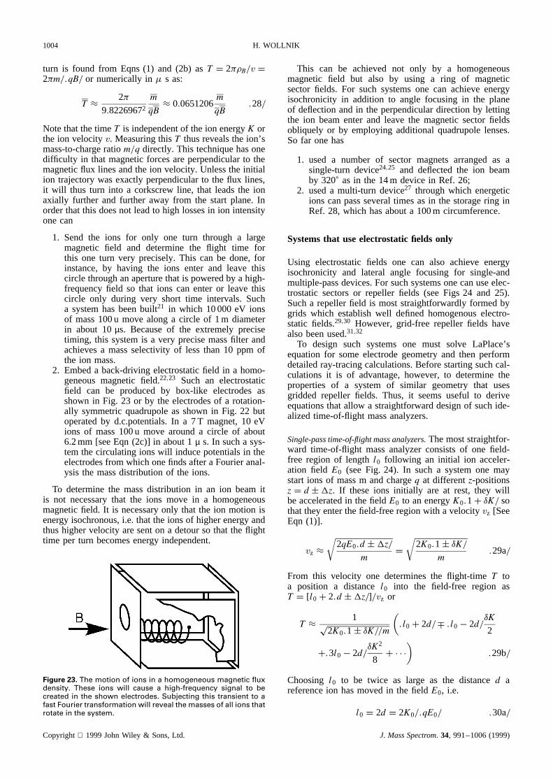
turn is found from Eqns (1) and (2b) asT D 2��B/v D2�m/.qB/ or numerically in� s as:
T ³ 2�
9.82269672m
qB³ 0.0651206
m
qB.28/
Note that the timeT is independent of the ion energyK orthe ion velocityv. Measuring thisT thus reveals the ion’smass-to-charge ratiom/q directly. This technique has onedifficulty in that magnetic forces are perpendicular to themagnetic flux lines and the ion velocity. Unless the initialion trajectory was exactly perpendicular to the flux lines,it will thus turn into a corkscrew line, that leads the ionaxially further and further away from the start plane. Inorder that this does not lead to high losses in ion intensityone can
1. Send the ions for only one turn through a largemagnetic field and determine the flight time forthis one turn very precisely. This can be done, forinstance, by having the ions enter and leave thiscircle through an aperture that is powered by a high-frequency field so that ions can enter or leave thiscircle only during very short time intervals. Sucha system has been built21 in which 10 000 eV ionsof mass 100 u move along a circle of 1 m diameterin about 10µs. Because of the extremely precisetiming, this system is a very precise mass filter andachieves a mass selectivity of less than 10 ppm ofthe ion mass.
2. Embed a back-driving electrostatic field in a homo-geneous magnetic field.22,23 Such an electrostaticfield can be produced by box-like electrodes asshown in Fig. 23 or by the electrodes of a rotation-ally symmetric quadrupole as shown in Fig. 22 butoperated by d.c.potentials. In a 7 T magnet, 10 eVions of mass 100 u move around a circle of about6.2 mm [see Eqn (2c)] in about 1µ s. In such a sys-tem the circulating ions will induce potentials in theelectrodes from which one finds after a Fourier anal-ysis the mass distribution of the ions.
To determine the mass distribution in an ion beam itis not necessary that the ions move in a homogeneousmagnetic field. It is necessary only that the ion motion isenergy isochronous, i.e. that the ions of higher energy andthus higher velocity are sent on a detour so that the flighttime per turn becomes energy independent.
Figure 23. The motion of ions in a homogeneous magnetic fluxdensity. These ions will cause a high-frequency signal to becreated in the shown electrodes. Subjecting this transient to afast Fourier transformation will reveal the masses of all ions thatrotate in the system.
This can be achievednot only by a homogeneousmagnetic field but also by using a ring of magneticsectorfields. For such systemsone can achieveenergyisochronicity in addition to angle focusing in the planeof deflectionandin the perpendiculardirectionby lettingthe ion beamenterand leave the magneticsectorfieldsobliquely or by employingadditionalquadrupolelenses.So far onehas
1. used a number of sector magnetsarrangedas asingle-turndevice24,25 and deflectedthe ion beamby 320° asin the 14m devicein Ref. 26;
2. useda multi-turn device27 throughwhich energeticions canpassseveraltimesasin the storagering inRef. 28, which hasabouta 100m circumference.
Systemsthat useelectrostatic fields only
Using electrostaticfields one can also achieve energyisochronicity and lateral angle focusing for single-andmultiple-passdevices.For suchsystemsonecanuseelec-trostatic sectorsor repeller fields (seeFigs 24 and 25).Sucha repellerfield is moststraightforwardlyformedbygrids which establishwell definedhomogenouselectro-static fields.29,30 However,grid-free repeller fields havealsobeenused.31,32
To design such systemsone must solve LaPlace’sequationfor someelectrodegeometryand then performdetailedray-tracingcalculations.Beforestartingsuchcal-culations it is of advantage,however,to determinetheproperties of a system of similar geometry that usesgridded repeller fields. Thus, it seemsuseful to deriveequationsthatallow a straightforwarddesignof suchide-alizedtime-of-flight massanalyzers.
Single-passtime-of-flightmassanalyzers.Themoststraightfor-ward time-of-flight massanalyzerconsistsof one field-free region of length l0 following an initial ion acceler-ation field E0 (seeFig. 24). In such a systemone maystart ions of massm andcharge q at differentz-positionsz D dšz. If theseions initially are at rest, they willbeacceleratedin thefield E0 to anenergy K0.1C υK/ sothattheyenterthefield-freeregionwith a velocity vz [SeeEqn (1)].
vz ³√
2qE0.dšz/m
D√
2K0.1š υK/m
.29a/
From this velocity one determinesthe flight-time T toa position a distance l0 into the field-free region asT D [l0C 2.dšz/]/vz or
T ³ 1p2K0.1š υK//m
(.l0C 2d/Ý .l0 � 2d/
υK
2
C.3l0� 2d/υK2
8C Ð Ð Ð
).29b/
Choosing l0 to be twice as large as the distanced areferenceion hasmovedin the field E0, i.e.
l0 D 2d D 2K0/.qE0/ .30a/
Copyright 1999JohnWiley & Sons,Ltd. J. MassSpectrom. 34, 991–1006(1999)

ION OPTICS IN MASS SPECTROMETERS 1005
Figure 24. A to first order energy-isochronous time-of-flightmass analyzer in which the product of the ion charge q, therepeller field strength E0 and the length l0 that follows thisrepeller field is chosen to be twice the electrostatic rigidity of theions, i.e. l0qE0 D 2K0, as has been expressed in Eqn (30a). In sucha system, one finds that to first order all ions, that simultaneouslystarted at differentz positions will arrive simultaneously at theion detector a distance l0 into the field-free region [see Eqn (30b)]with only a small error that is proportional to υK 2, if šυK is therelative energy spread of the ions.
Figure 25. A full time-of-flight mass analyzer that consists of(1) a small31 energy-isochronous linear time-of-flight systemforming a first time focus in 25 and (2) an energy-isochronous ionreflector system that focuses the ions laterally and longitudinallyto a final time focus. Note that for most cases l1 C l2 × l0. Forsuch systems one usually postulates .T jK / D 0 in Eqn 32 andadditionally .T jKK / D 0 so that the overall flight time T is widelyindependent of υK, the relative energy spread of the ions, withan error proportional to .T jKKK /υK 3.
onefinds that in Eqn (29b) the term thatdependslinearlyon υK vanishes.This is the condition for a first-orderenergy isochronicity.In this casetheoverall flight time is
T D T0.1C υK2/8C Ð Ð Ð/ .30b/
with T0 beingnumerically2l0/.9.8226967p
2K0/m/. Ex-cept for termsproportionalto υK2 in sucha system,allions will arrive at the sametime at a position a distancel0 into the field-free region.This is true also if the ionswere startedfrom different z-positionsdšz, althoughthis will causetheir final energiesto beK0.1š υK/ withK0υK D zqE0, which often resultsin υK > 10%.
If the ions were not at rest initially but rathermovedwith an initial velocityšvzi, in otherwords,if theyhadan initial energy Ki D vzi
2m/2D zE0q, they wouldneedthe time
t D šKi
qE0vzi/2or numericallyt ³
√2Kim
9.8226967qE0
.31/
in µs to lose this energy Ki in a field E0. Here againm and q are in mass and charge units, respectively,E0 is in V mm�1 and Ki in eV. This time is 50%of the so-called turn around time 2Tt which at theend is an unavoidablespreadin the overall flight timeT. For well designedtime-of-flight massanalyzersthis2Tt is usuallythequantitythat limits themass-resolvingpower Rm D T/.2T/ ³ T/.4Tt/. Note that Tt isproportionalto
pKi/E0. Henceit is helpful to increase
E0 andto decreaseKi .For high-performancetime-of-flight mass analyzers,
one advantageouslydivides the repeller field in Fig. 24into two sections of field strengthsE3 and E4 (seeFig. 25), andadjuststhesefield strengthsappropriately.32
In the systemshownin Fig. 25, also the ion accelerationfield is divided into two sectionsE1 andE2, althoughthissplitting is not alwaysnecessaryif l0 is short.A completetime-of-flight massanalyzerthusmay contain
1. one usually rathersmall reflectorfield that is inte-gratedinto thepulsedion sourceto form anenergy-isochronouslinear time-of-flight system;
2. one much larger reflector field which acts like amirror for the ion beam and directs it energy-isochronouslyto a detector.
If the ions are formedat d1 C d2 in Fig. 25, they gainthe energy .E1d1 C E2d2/q D K0 so that the ions movein the field-free region of length l0C l1 with a veloc-ity vz0 D
p2K0/m. Theseions thenarepassedthrougha
reflectorthat consistsof anotherrepellerfield divided intwo sectionsin which theionsfirst losetheir energy in thefieldsE1 andE2 andthengain it back.The overall flighttime, althoughdifficult to expressmathematically32,33 inthis case,canbe describedby
T D T0C .TjK/υK C .TjKK/υK2 C .TjKKK/υK3 C Ð Ð Ð.32/
T0vz0 D l0 C l1C l2C .1� �1p�1/
ð 2d1/.1� �1/C .1� �2p�2/
ð 4d3/.1� �2/
4.TjK/vz0 D �.l0 C l1C l2/C .1� �1/p�1/
ð 2d1/.1� �1/C .1� �2/p�2/
ð 4d3/.1� �2/
Copyright 1999JohnWiley & Sons,Ltd. J. MassSpectrom. 34, 991–1006(1999)
1006 H. WOLLNIK
32.TjKK/vz0 D 3.l0 C l1 C l2/C .1� �1/p�1
3/
ð 2d1/.1� �1/C .1� �2/p�2
3/
ð 4d3/.1� �2/
128.TjKKK/vz0 D �5.l0 C l1C l2/C .1� �1/p�1
5/
ð 2d1/.1� �1/C .1� �2/p�2
5/
ð 4d3/.1� �2/
with:
�1 D E1d1/.E1d1 C E2d2/ D E1d1q/K0 �1 D E2/E1� 1
�2 D E4d4/.E1d1 C E2d2/ D E4d4q/K0 �2 D E3/E4� 1
andvz0 being numerically 9.8226967√
2K0/m accordingto Eqn (1). Note that forE1 D E2 and l1 D l2 D d3 D 0,Eqn (32) turns into Eqn (30b).
A time-of-flight mass analyzer according to Eqn (32)can be turned into a first-order energy-isochronous time-of-flight mass analyzer, for which the term.TjK/ van-ishes. To achieve this one must modify the devicesuch that
2d2.1C �1/p�1/ D l0.1� �1/ .33a/
and 4d3.1C �2/p�2/ D .l1 C l2/.1� �2/ .33b/
for instance by choosing�1 and�2 appropriately. In thiscase the coefficients of Eqn (32) become
T0vz0 D l0.1C �1/C .l1 C l2/.1C �2/
C 2d2C 4d3
4.TjK/vz0 D 0
32.TjKK/vz0 D 3.l0 C l1C l2/C .l0 � 2d1//�1
C .4d3 � l1� l2//�2
128.TjKKK/vz0 D �5.l0 C l1 C l2/C .l0 � 2d1//�12
C .4d3 � l1 � l2//�22
Choosing now �1 and �2 such that .l0 � 2d2//�1 C.l1 C l2� 4d3//�2 D 3.l0 C l1 C l2/, one finds.TjK/ D.TjKK/ D 0 and thusT D T0 C .TjKKK/υK3 C Ð Ð Ð. Insuch a time-of-flight mass analyzer one can very pre-cisely determineT even if υK is large. Note, however,that the turn around timešTt of Eqn (31) also in thiscase causes an additional spread of the overall flight time,which usually is the limiting quantity for a precise flight-time determination.
Multi-pass time-of-flight mass analyzers.Although one canachieve high-performance mass analyzers in single-passtime-of-flight mass analyzers, there are limitations to theachievable mass-resolving power because of a finite turn-around time defined in Eqn (31) and because of electroniclimitations in precise time measurements. Hence it can beadvantageous to use systems in which a given flight passis used repeatedly so that the ions fly for longer times.There are two solutions to this problem:
1. one can build a ring of electrostatic sector fields32–34
or a figure-of-eight race track;24,36
2. one can use a multiple reflecting system in whichions are bounced back and forth between two orthree grid-free ion mirrors.35,37
Although the performance of ring solutions have beenlimited by mechanical tolerances,36 multiple reflectingsystems have achieved37 mass-resolving powers aboveRm D 50 000.
Acknowledgement
I am grateful to G. Cooks, M. Yavor, A. Dodonov and A. Tolmachevfor fruitful discussions and to W. Schott for help with the drawings.
REFERENCES
1. Wollnik H. Optics of Charged Particles. Academic Press:Orlando, FL, 1987.
2. Banford AP. The Transport of Charged Particle Beams. E&FNSpon: London, 1966.
3. Halliday D, Resnick R. Physics. Wiley: New York, 1977.4. Courant ED, Snyder HS, Ann. Phys. 1958; 3: 48.5. Dayton IE, Shoemaker FC, Mozley RF. Rev. Sci. Instrum.
1954; 25: 485.6. Smith D et al. Rapid Commun. Mass Spectrom.7. Barber NF. Proc. Leeds Philos. Soc., Sci. Sect. 2 1953; 427.8. Herzog R. Acta Phys. Austriaca 1950; 4: 431.9. Aston FW. Philos. Mag. 1919; 38: 709.
10. Mattauch J, Herzog R. Z. Phys. 1934; 89: 786.11. Wollnik H. Nucl. Instrum. Methods in press.12. Antl M, Wollnik H. Nucl. Instrum. Methods 1989; A274: 45.13. Douglas DJ, French JB. J. Am. Soc. Mass Spectrom 1992; 3:
398.14. Bollen G, et al. Nucl. Instrum Methods 1996; A368: 675.15. Dodonov A, et al. Rapid Commun. Mass Spectrom. 1997; 11:
649.16. Tolmachev A. personal communication.17. Paul W, Steinwedel H. Z. Naturforsch., Teil A 1953; 8: 448.18. Dawson PH. Quadrupole Mass Spectrometry and Applica-
tions. Elsevier: New York, 1976.19. Yost E, Enke C.
20. Stafford G, et al. Int. J. Mass Spectrom. Ion Processes 1984;60: 85.
21. de Saint Simon M. et al. Phys. Scr. 1995; T59: 406.22. Marshall AG, Schweikart L. Int. J. Mass Spectrom Ion
Processes 1992; 118/119: 37.23. Konig M, et al. Int. J. Mass Spectrom Ion Processes 1995;
142: 95.24. Poschenrieder W. Int. J. Mass Spectrom. Ion Processes Phys.
1972; 9: 35.25. Wollnik H. Nucl. Instrum Methods 1981; 186: 441.26. Wouters JM, et al. Nucl. Instrum. Methods 1985; 240: 77.27. Wollnik H. Nucl. Instrum. Methods 1987; 326: 267.28. Schlitt et al. Nucl. Phys. 1997; A626: 315c.29. Wiley WC, Mclaren IH. Rev. Sci. Instrum. 1955; 26: 150.30. Mamyrin BA, et al. Sov. Phys. JETP 1973; 37: 45.31. Wollnik H, et al. In Proc. J-C Symp. on Mass Spectr.
Matsuda H, Liang X (eds). Bando Press: Osaka, 1987; 181.32. Wollnik H. In Biological Mass Spectrometry. Matsuo T (ed).
San- El Publ.: Kyoto, 1992; 204.33. Wollnik H. In Mass Spectrometry in Biological Sciences.
Caprioli et al. (eds). Kluwer: Dordrecht, 1996; 111.34. Wollnik H. Nucl. Phys. A in press.35. Wollnik H, Przewloka M. Int. J. Mass Spectrom. Ion Pro-
cesses 1990; 96: 267.36. Matsuo T, et al. ASMS Abstracts 1999.37. Casares A, et al. ASMS Abstracts 1999.
Copyright 1999 John Wiley & Sons, Ltd. J. Mass Spectrom. 34, 991–1006 (1999)