iol power calculation normal and post lasik eyes
TRANSCRIPT

IOL POWER CALCULATION
NORMAL & POST LASIK EYES
INDOREDRISHTI.WORDPRESS.COM

DR DINESH MITTAL DR SONALEE MITTAL
DRISHTI EYE HOSP VIJAYNAGAR INDORE


1 Cataract surgery has evolved into a refractive procedure with the goal of eliminating or significantly reducing the need for spectacle dependence.•2. One must consider not only the astigmatism induced by the cataract incision itself, but also the correction of preexisting astigmatism.•3. Incision length, depth, and distance from visual axis all affect astigmatism.

•4. LRIs are commonly used to correct preexisting astigmatism, and•published nomograms are helpful in tailoring a surgical approach.•5. Toric IOLs and excimer laser ablation are alternative approaches to correcting astigmatism in the patient for refractive cataract surgery.•No single approach is best suited for all patients.
INTRAOCULAR LENS CALCULATIONS•Choosing the appropriate IOL power is a major determinant of patient satisfaction with cataract surgery. •3 main factors •accurate measurements (biometry), •selecting calculations (formulas),• and assessing the patient’s needs to determine postoperative refractive target (clinical considerations).
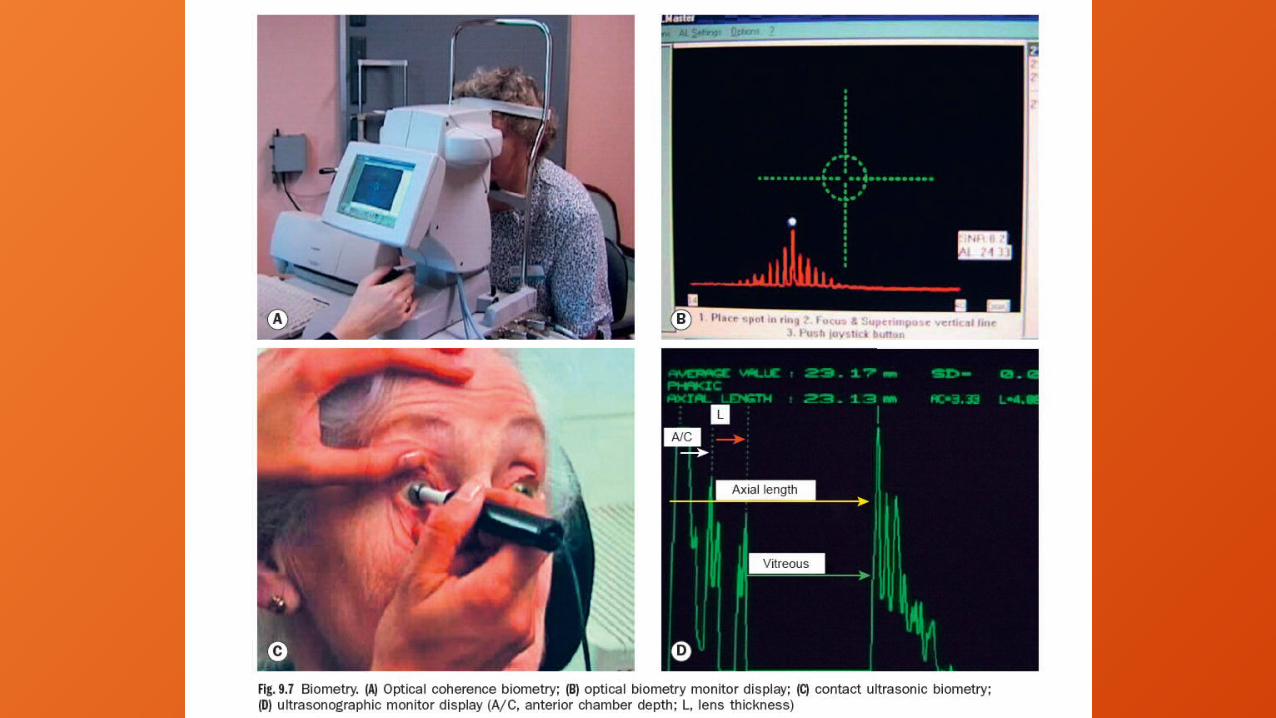

BIOMETRY•At minimum, 2 measurements reqd to calculate implant power:•axial length & corneal curvature (keratometry) •Precise measurements critical •error of 0.3 mm in axial length will result in a 1-D error in IOL power.

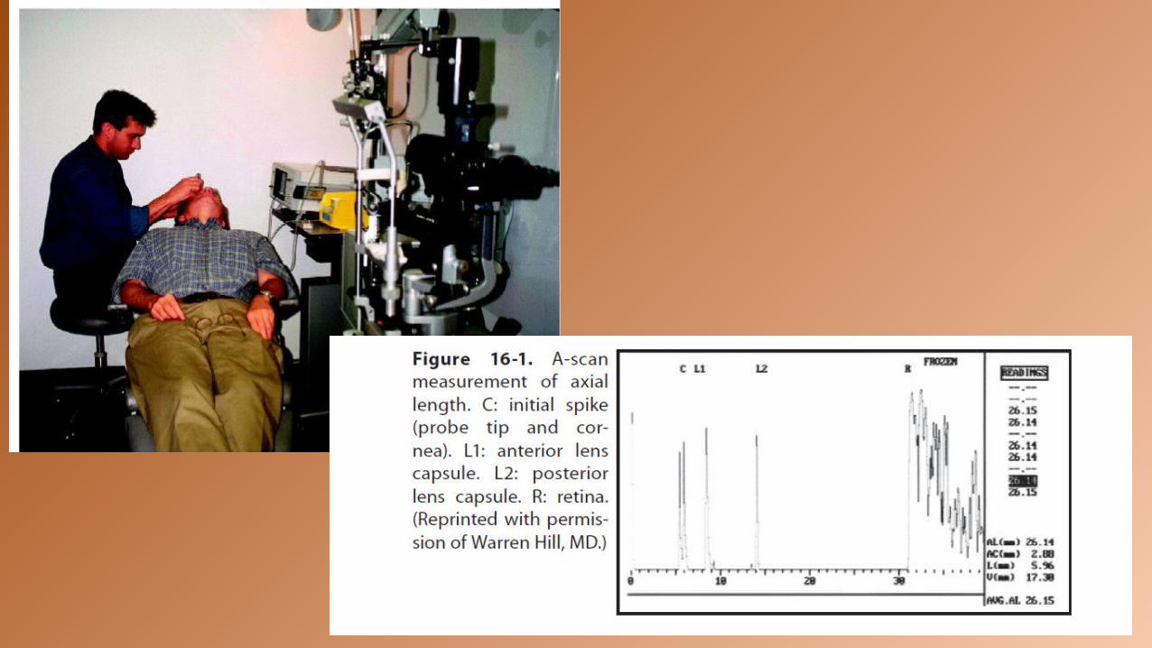
Axial Length•Axial length has been obtained utilizing A-SCAN ULTRASOUND. •This measurement is determined by calculation;• an ultrasound pulse is applied and the transit time through the eye is measured. Using estimated velocities of ultrasound waves through various media (ie, cornea, aqueous, lens, and vitreous) the distance travelled through the eye is calculated.

• The instrument should have an oscilloscope screen to differentiate a good measurement from a poor one. Characteristic echo peaks or spikes should be observed when the probe is aligned properly • These include the following: a tall peak for the cornea,
tall peaks for the anterior and posterior lens capsule, tall peak for the retina, mod-erate peak for the sclera, and moderate-to-low peaks for orbital fat. If these spikes are not well seen, then the probe may be misaligned.
A SCAN ULTRASOUND

•The contact A-scan technique must be performed carefully, as com-pressing the cornea will result in a shorter-than-expected measurement and multiple measurements should be taken and averaged. • If several are taken and differ by a significant amount, they should be discarded until consistent readings can be obtained.

• It is also prudent to measure both eyes for comparison•the machine should be regularly calibrated, checking measurements against an eye of known axial length.

Immersion techniqueThe immersion technique may more accurately represent the true axial length because there is no corneal compression.
In this technique, the patient lies in the supine position and a scleral shell is placed on the eye and filled with Goniosol. The ultrasound probe is placed in this solution and the beam is aligned with the macula by having the patient look at the probe tip fixation light.
Although the immersion method may be strongly advocated by some users, applanation A-scan is the more commonly used method

IMMERSION TECHNIQUE SHOWING PROBE IN OSSOINIG SHELL

Optical biometry: IOLMaster• In the last decade, the technique of optical coherence biometry was in-troduced by Haigis, which utilizes light rather than ultrasound to measure the length of the eye. The first device introduced was the IOLMaster (Zeiss), based on the principle of partial coherence interferometry using a 780-nm multimode laser diode.


•Measurements taken without contact to eye, thus eliminating variability due to an examiner technique. •The distance measured lies between the anterior surface of tear film & retinal pigmented pigment epithelium (rather than the anterior surface of the cornea and internal limiting membrane ), which may be more physiologically accurate (refractive rather than anatomic axial length).
2 advantages to the IOLMaster

patient asked to focus on a small red fixation light, & examiner maneuvers focusing spot within the measurement reticule, sampling areas until the best peak pattern is obtained. 5 to 20 measurements obtained until the readings differ by less than 0.1 mm. Maximal axial length measured 40 mm.
IOLMASTER USE

IOL MASTER DISADVANTAGE
The primary disadvantage of this optical device is that any significant axial opacity, such as a corneal scar, dense posterior subcapsular plaque, darkly brunescent cataract, or vitreous hemorrhage, will reduce the signal-to-noise ratio (SNR) to the point that reliable measurements are not possible.
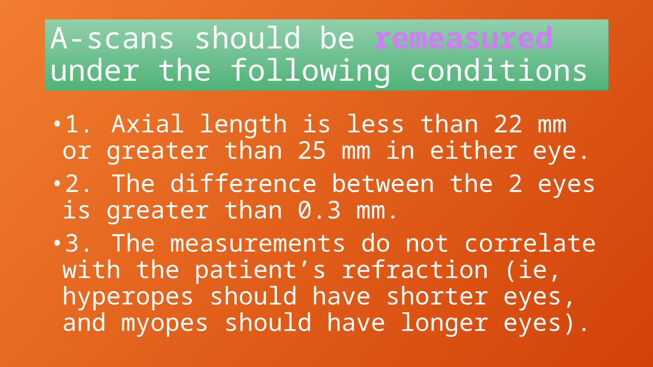
A-scans should be remeasured under the following conditions•1. Axial length is less than 22 mm or greater than 25 mm in either eye.•2. The difference between the 2 eyes is greater than 0.3 mm.•3. The measurements do not correlate with the patient’s refraction (ie, hyperopes should have shorter eyes, and myopes should have longer eyes).

Lens power calculation formulas evolved over past 30 yrs, since first theoretical formula for iris-supported iol published by Fyodorov in 1967.

First Generation• Initial formulas were based largely on axial length,
but with the availability of posterior chamber implants, consideration had to be given to the distance from the cornea to the implant (anterior chamber depth). By studying large numbers of cases, linear regression techniques were used to determine a formula for predicting emmetropic implant power. The most widely used regression formula was developed by Sanders, Retzlaff , and Kraff in 1980 and is known as the SRK formula.
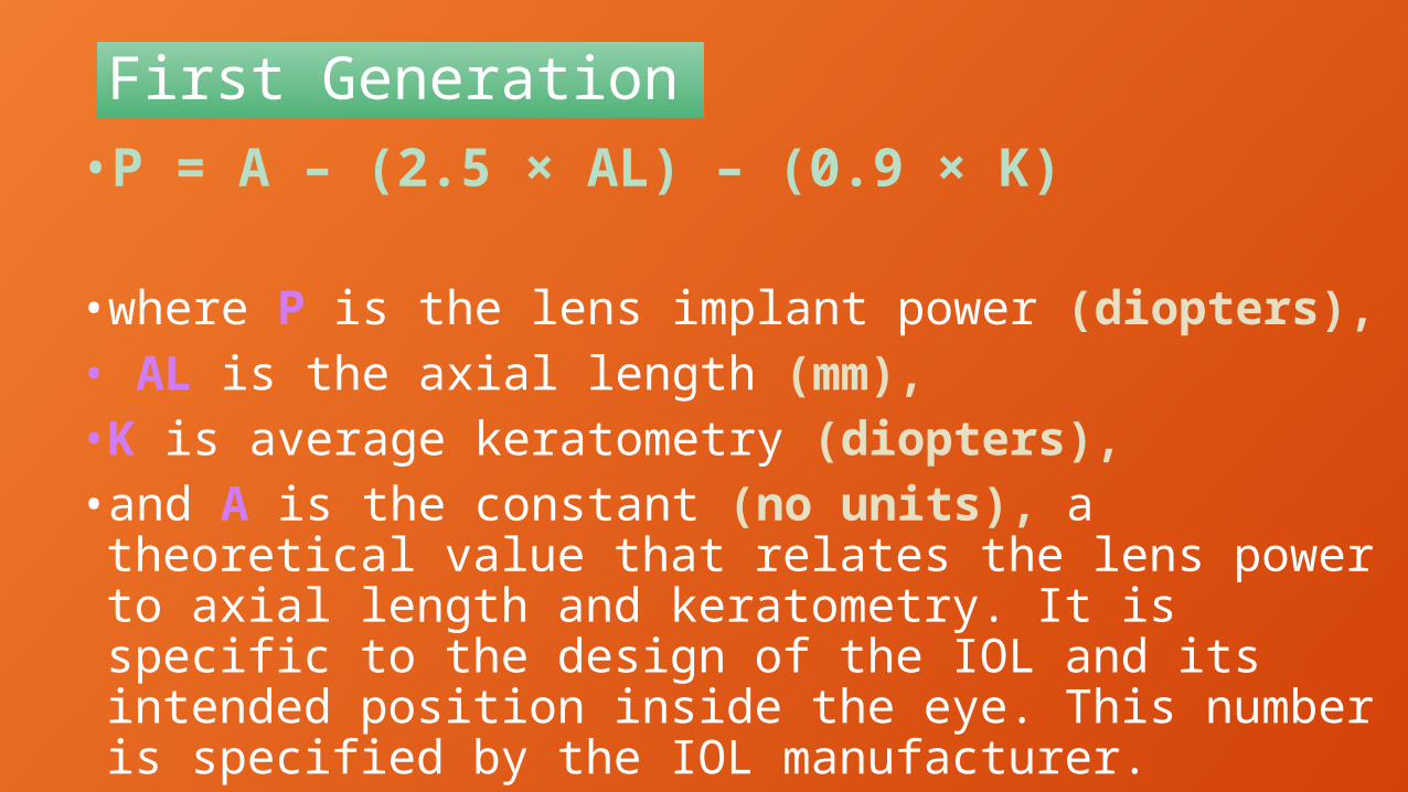
First Generation•P = A – (2.5 × AL) – (0.9 × K)
•where P is the lens implant power (diopters),• AL is the axial length (mm), •K is average keratometry (diopters), • and A is the constant (no units), a theoretical value that relates the lens power to axial length and keratometry. It is specific to the design of the IOL and its intended position inside the eye. This number is specified by the IOL manufacturer.

Second Generation• The SRK formula is a linear equation derived by fitting collected data to a straight line. However, the optical system is nonlinear and begins to produce significant error with short or long eyes. To improve accuracy, the formula was modified, taking into consideration variation in axial length. • This en-hancement is known as the SRK II formula in which the A-constant is defined at different axial lengths:

Second Generation SRK II •A = A + 3 (AL < 20 mm)•A = A + 2 (20 mm < AL < 21 mm) •A = A + 1 (21 mm < AL < 22 mm)• A = A (22 mm < AL < 24.5 mm) •A = A – 0.5 (24.5 mm < AL)
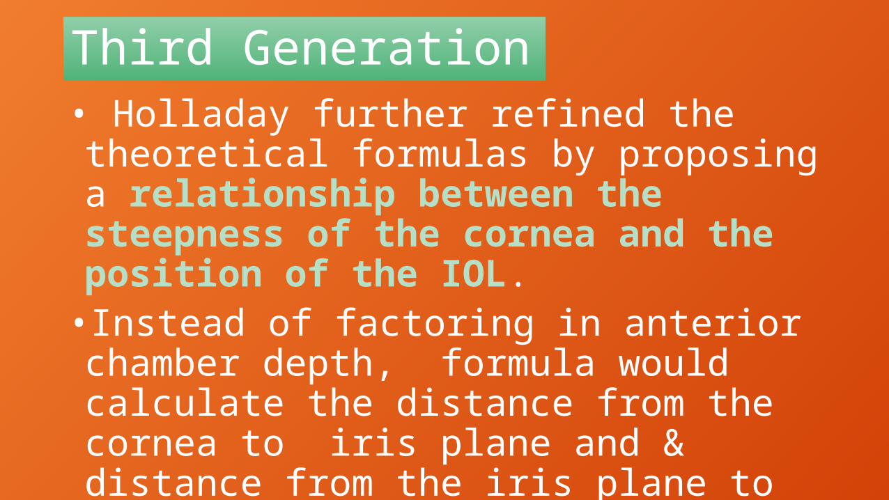
Third Generation• Holladay further refined the theoretical formulas by proposing a relationship between the steepness of the cornea and the position of the IOL. • Instead of factoring in anterior chamber depth, formula would calculate the distance from the cornea to iris plane and & distance from the iris plane to the IOL.


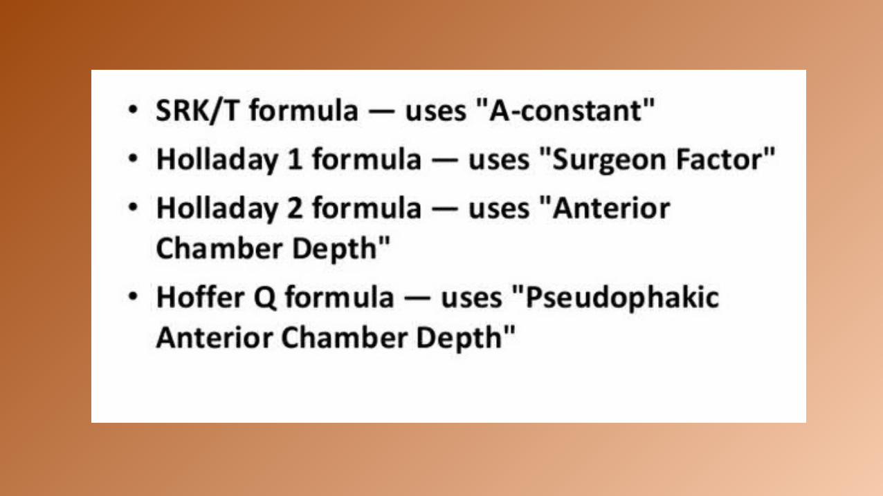
Third Generation• . This second variable was termed the surgeon factor, was specific to each lens, and had the ability to be personalized and adjust for any consistent bias in the surgeon’s results. Hoffer achieved the same effect via another approach in his Hoffer Q formula. Retzlaff followed suit to take into consideration not only the position of the implant, but also incorporated a correction for the retinal thickness, thus developing the SRK/T formula in 1990.

Fourth Generation• Haigis presented the notion that geometry of each IOL model should be considered in determining which formula to use. The geometry for a particular IOL model is not the same at all powers; therefore, the Haigis formula utilizes 3 lens constants to address it•a0 constant moves the power prediction curve up or down a1 constant is tied to the anterior chamber depth a2 constant is tied to the measured axial length
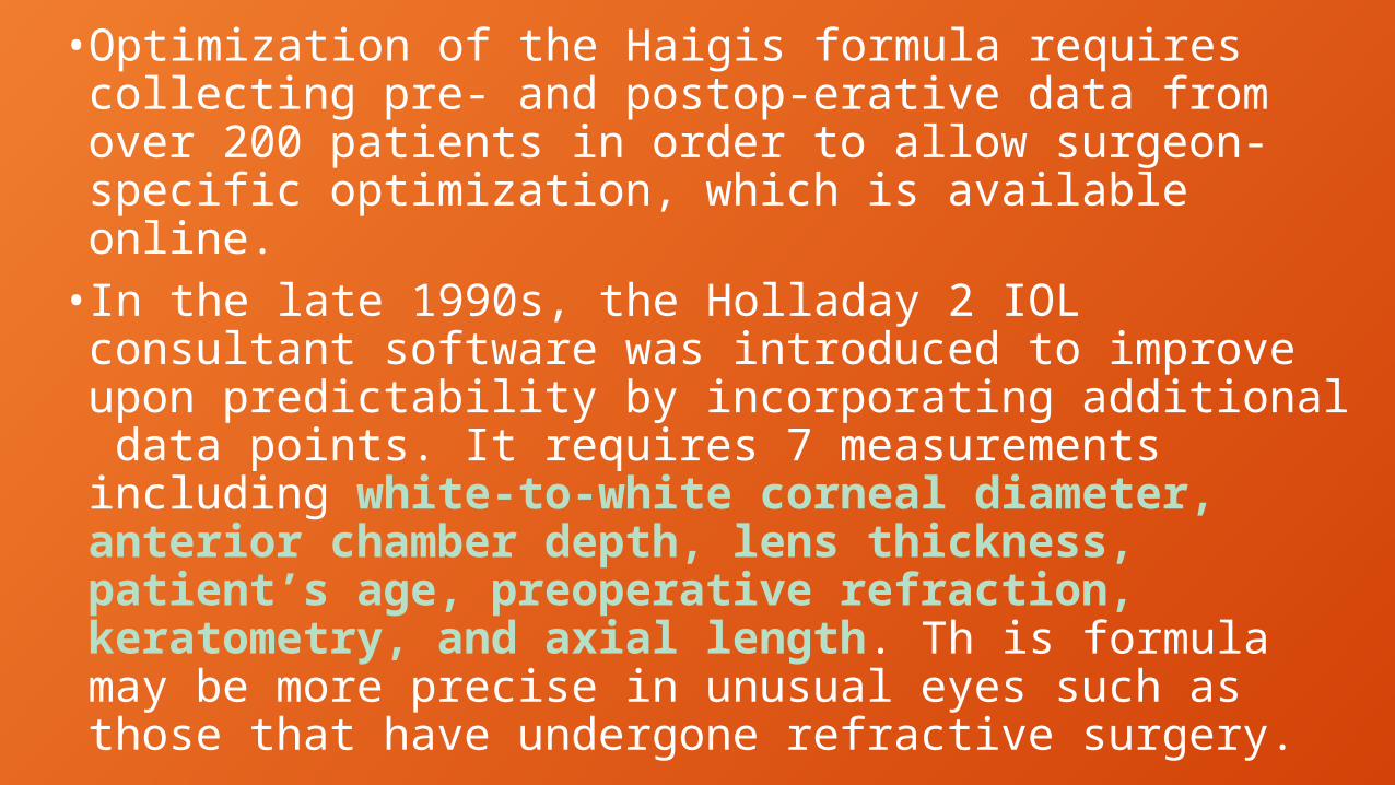
•Optimization of the Haigis formula requires collecting pre- and postop-erative data from over 200 patients in order to allow surgeon-specific optimization, which is available online.• In the late 1990s, the Holladay 2 IOL consultant software was introduced to improve upon predictability by incorporating additional data points. It requires 7 measurements including white-to-white corneal diameter, anterior chamber depth, lens thickness, patient’s age, preoperative refraction, keratometry, and axial length. Th is formula may be more precise in unusual eyes such as those that have undergone refractive surgery.

•One or more of the third-generation formulas (SRK/T, Holladay 1, and Hoffer Q) are generally programmed into A-scan biometers sold today. •The optical biometers are now incorporating the fourth-generation formulas (Haigis and Holladay 2).•Over time, some trends have emerged regarding which formulas to use in general categories of patients:


THEORETICAL FORMULAE BASED ON MATHEMATICAL PRINCIPLES REVOLVING AROUND THE SCHEMATIC EYEREGRESSION FORMULAE WORKING BACKWARDS ON POSTOPERATIVE OUTCOMES3RD AND 4TH GENERATION MIX OF BOTH

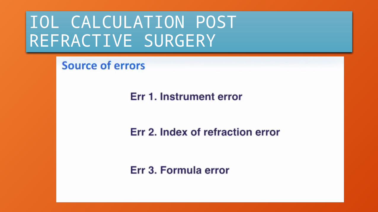
IOL CALCULATION POST REFRACTIVE SURGERY

INSTRUMENT ERRORINSTRUMENT ERROR IS BECAUSE KERATOMETERS READ AT 3.2 MM AND NOT AT THE CENTRE

INDEX OF REFRACTION ERRORTHIS K READING ERROR OCCURS BECAUSE OF CHANGED RATIO OF RADIUS OF CURVATURE OF ANTERIOR AND POSTERIOR SURFACE OF CORNEA SECONDARY TO KERATO REFRACTIVE PROCEDURE

UNOPERATED EYES IN UNOPERATED EYES THE RATIO BETWEEN ANTERIOR AND POSTERIOR SURFACE OF CORNEA IS 1.21

MYOPIC OPERATED EYES
IN OPERATED EYE THIS RATIO CHANGES

POST MYOPIA TREATED EYES KERATOMETRY OVER ESTIMATED

POST HYPERMETROPIA TREATED EYES

POST HYPEROPIA TREATED EYES KERATOMETRY UNDER ESTIMATED
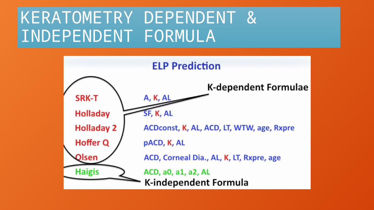
KERATOMETRY DEPENDENT & INDEPENDENT FORMULA

HOW TO CALCULATE IOL POST KERATO REFRACTIVE SURGERY

ARAMBERRI DOUBLE K METHOD
PRE OP K READING FOR ELP
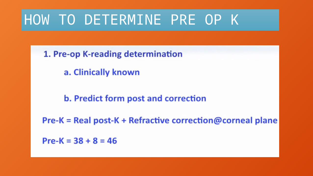
HOW TO DETERMINE PRE OP K

PRE OP K READING

PRE OP K READING
TRUE POST OP K READING FOR IOL POWER CALCULATION

MEASUREMENT OF POST OP K READING

POST OP K READING HISTORY DEPENDENT
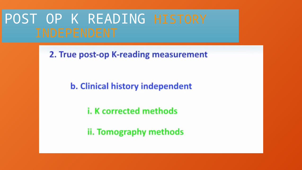
POST OP K READING HISTORY INDEPENDENT

K CORRECTED METHODS
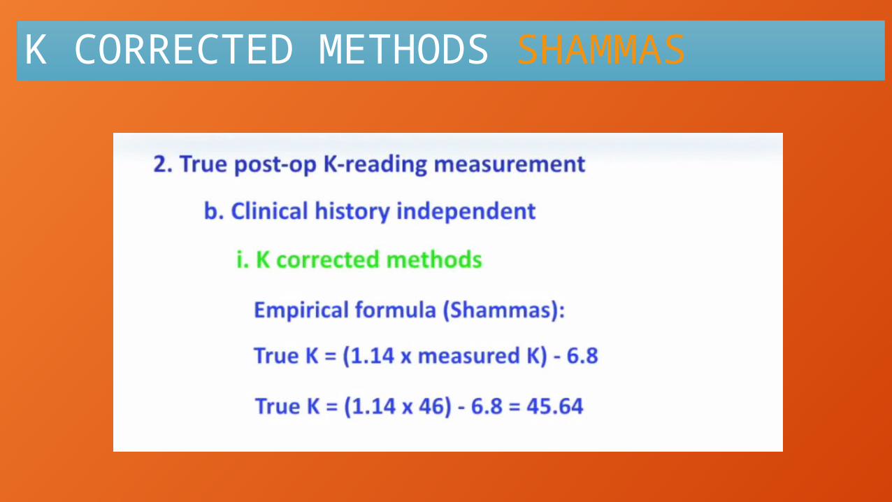
K CORRECTED METHODS SHAMMAS

K CORRECTED METHODS THEORETICAL

K CORRECTED KOCH & WANG

POST OP K READING TOMOGRAPHY METHODS
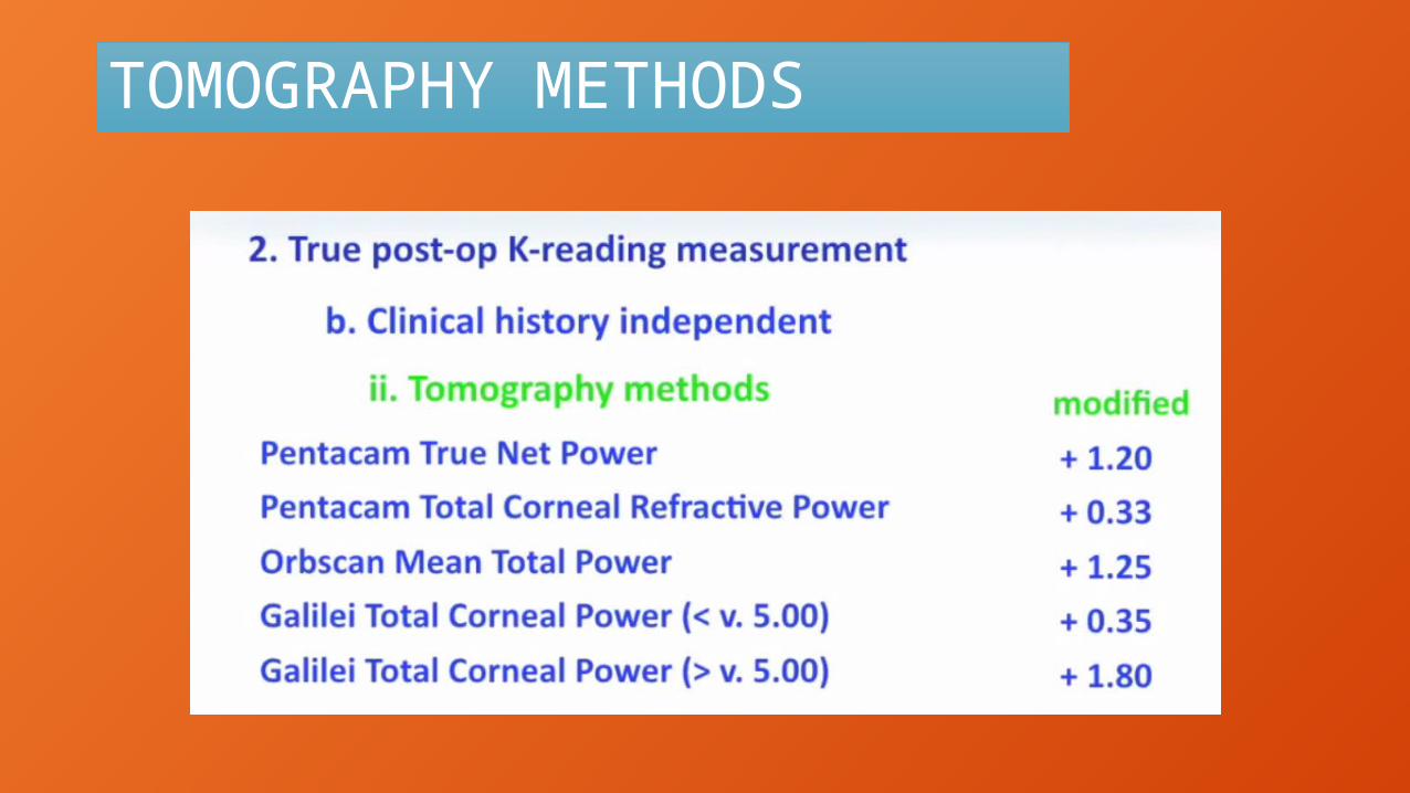
TOMOGRAPHY METHODS

HEIDELBERG RAYTRACING STUDY
FOUR FORMULAS ARE BESTHAIGISHOFFER QOLSEN 2RAYTRACING

IOL CALCULATION BEST IN UNOPERATED EYES

IOL CALCULATION BEST POST KERATOREFRACTIVE SURGERY
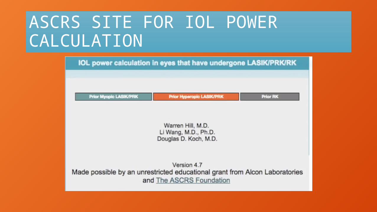
ASCRS SITE FOR IOL POWER CALCULATION

THANK YOUDR DINESHDR SONALEE