invt imars b series grid-tied solar inverter user manual
TRANSCRIPT

Operation Manual iMars
INVT Solar Technology (Shenzhen) Co., Ltd.


1
Preface The manual is intended to provide detailed information of product information, installation,
application, trouble shooting, precautions and maintenance of iMars series grid-tied solar inverters.
The manual does not contain all the information of the photovoltaic system. Please read this
manual carefully and follow all safety precautions seriously before any moving, installation,
operation and maintenance to ensure correct use and high performance of operation on the
inverter.
The use of the iMars series grid-tied solar inverters must comply with local laws and regulations on
grid-tied power generation.
The manual needs to be kept well and be available at all times.
All rights reserved. The contents in this document are subject to change without notice.
There may be data deviation because of product improving. Detailed information is in accordant
with the final product.
iMars grid-tied solar inverters Content
2
Contents Preface ................................................................................................................................................ 1 Contents ............................................................................................................................................. 2 1 Safety precautions ......................................................................................................................... 5
1.1 Icons ........................................................................................................................................ 6
1.2 Safety guidelines ..................................................................................................................... 6
1.2.1 Delivery and installation ...............................................................................................................7
1.2.2 Grid-tied operation .........................................................................................................................8
1.2.3 Maintenance and inspection........................................................................................................8
1.2.4 What to do after scrapping...........................................................................................................9
2 Product overview ......................................................................................................................... 10 2.1 Solar grid-tied power generation system .............................................................................. 11
2.1.1 Supported grid connection structure ...................................................................................... 11
2.2 Products appearance ............................................................................................................ 12
2.2.1 Three-phase inverter .................................................................................................................. 12
2.3 Name plate ............................................................................................................................ 14
2.4 DRM instruction ..................................................................................................................... 15
2.5 Models ................................................................................................................................... 16
2.6 Dimensions and weight ......................................................................................................... 17
3 Storage........................................................................................................................................... 18 4 Installation ..................................................................................................................................... 19
4.1 Unpacking inspection ............................................................................................................ 20
4.2 Before installation .................................................................................................................. 21
4.2.1 Installation tools........................................................................................................................... 21
4.2.2 Installation place............................................................................................................................. 22
iMars grid-tied solar inverters Content
3
4.2.3 Connection cables........................................................................................................................... 24
4.2.4 Miniature circuit breakers.............................................................................................................. 24
4.3 Mechanical installation .......................................................................................................... 25
4.3.1 Installation of three-phase inverter .............................................................................................. 25
4.4 Electrical installation.............................................................................................................. 28
4.4.1 Connection of solar modules ......................................................................................................... 29
4.4.2 AC connection of 12kW / 15kW / 17kW / 20kW / 25kW / 30kW inverter ................................. 30
5 Operation ......................................................................................................................................... 33 5.1 Inspection before operation .................................................................................................. 34
5.2 Grid-tied operation ................................................................................................................ 34
5.3 Stopping................................................................................................................................. 35
5.4 Daily maintenance ................................................................................................................. 35
5.4.1 Regular maintenance ..................................................................................................................... 35
5.4.2 Maintenance guide ......................................................................................................................... 36
6 Display panel .................................................................................................................................... 39 6.1 LED indicators ....................................................................................................................... 40
6.2 Operation panel ..................................................................................................................... 41
6.3 LCD screen............................................................................................................................ 41
6.4 Functions operation ............................................................................................................... 42
6.4.1 Monitoring parameters .................................................................................................................. 42
6.4.2 History ............................................................................................................................................. 43
6.4.3 Statistics .......................................................................................................................................... 44
6.4.4 Parameter settings ......................................................................................................................... 44
6.4.5 System Information ........................................................................................................................ 51
6.4.6 Faults ............................................................................................................................................... 51

iMars grid-tied solar inverters Content
4
6.4.7 Inverter control ............................................................................................................................... 51
6.4.8 Mode settings ................................................................................................................................. 52
6.5 Grid Certification Choice ....................................................................................................... 53
7 Monitoring communication............................................................................................................... 55 7.1 Standard communication ...................................................................................................... 56
7.2 Optional communication ....................................................................................................... 57
7.3 RS485-DRM ports ................................................................................................................. 58
8 Troubleshooting ............................................................................................................................... 59 9 Contact us......................................................................................................................................... 63 10 Technical parameters ...................................................................................................................... 64

iMars grid-tied solar inverters Safety precautions
5
1 Safety precautions iMars series grid-tied solar inverters are designed and tested strictly in accordance with relevant
international safety standards. As an electrical and electronic device, all relevant safety regulations
must be strictly complied during installation, operation, and maintenance. Incorrect use or misuse
may result in
Injury to the life and personal safety of the operator or other people.
Damage to the inverter or other property belonging to the operator or other people.
In order to avoid personal injury, damage to the inverter or other devices, please strictly observe
the following safety precautions.
This chapter mainly describes various warning symbols in operation manual and provides safety
instructions for the installation, operation, maintenance and use of the iMars series grid-tied solar
inverters.
iMars grid-tied solar inverters Safety precautions
6
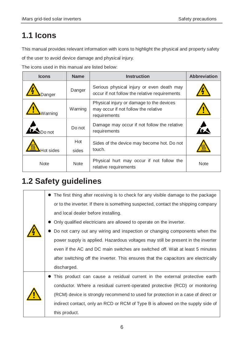
1.1 Icons This manual provides relevant information with icons to highlight the physical and property safety
of the user to avoid device damage and physical injury.
The icons used in this manual are listed below:
Icons Name Instruction Abbreviation
Danger Danger
Serious physical injury or even death may occur if not follow the relative requirements
Warning Warning
Physical injury or damage to the devices may occur if not follow the relative requirements
Do not Do not
Damage may occur if not follow the relative requirements
Hot sides
Hot
sides Sides of the device may become hot. Do not touch.
Note Note Physical hurt may occur if not follow the relative requirements
Note
1.2 Safety guidelines
The first thing after receiving is to check for any visible damage to the package
or to the inverter. If there is something suspected, contact the shipping company
and local dealer before installing.
Only qualified electricians are allowed to operate on the inverter.
Do not carry out any wiring and inspection or changing components when the
power supply is applied. Hazardous voltages may still be present in the inverter
even if the AC and DC main switches are switched off. Wait at least 5 minutes
after switching off the inverter. This ensures that the capacitors are electrically
discharged.
This product can cause a residual current in the external protective earth
conductor. Where a residual current-operated protective (RCD) or monitoring
(RCM) device is strongly recommend to used for protection in a case of direct or
indirect contact, only an RCD or RCM of Type B is allowed on the supply side of
this product.

iMars grid-tied solar inverters Safety precautions
7
Ensure that there is no electromagnetic interference from other electrical and
electronic equipments on the installation site.
Do not refit the inverter unauthorized.
All the electric installation needs to be compliance with the national or local laws
and standards.
The temperature of individual parts or the enclosure of the inverter–especially
the heat sink may become hot in normal operation. There is a danger of burning.
Do not touch.
Do not open the cover of inverters unauthorizedly. The electrical parts and
components inside the inverter are electrostatic. Take measurements to avoid
electrostatic discharge during relevant operation.
The inverter must be reliably grounded.
Ensure that DC and AC side circuit breakers have been disconnected and wait
at least 5 minutes before wiring and checking.
Note: Technical personnel who can perform installation, wiring, commissioning,
maintenance, troubleshooting and replacement of the iMars series grid-tied solar
inverters must meet the following requirements:
Operators need professional training.
Operators must read this manual completely and master the related safety precautions.
Operators need to be familiar with the relevant safety regulations for electrical systems.
Operators need to be fully familiar with the composition and operating principle of the
entire grid-tied photovoltaic power generation system and related standards of the
countries/regions in which the project is located.
Operators must wear personal protective equipment.
1.2.1 Delivery and installation
Keep the package and unit complete, dry and clean during storage and delivery.
Please remove and install the inverter with two or more people, because of the
inverter is heavy.
Remove and install the inverter with appropriate tools to ensure safe and normal
operation and avoid physical injury or death. The people also need mechanical
iMars grid-tied solar inverters Safety precautions
8
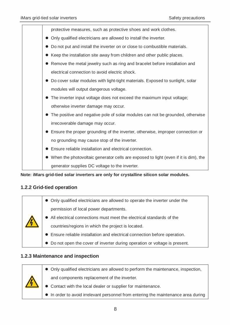
protective measures, such as protective shoes and work clothes.
Only qualified electricians are allowed to install the inverter.
Do not put and install the inverter on or close to combustible materials.
Keep the installation site away from children and other public places.
Remove the metal jewelry such as ring and bracelet before installation and
electrical connection to avoid electric shock.
Do cover solar modules with light-tight materials. Exposed to sunlight, solar
modules will output dangerous voltage.
The inverter input voltage does not exceed the maximum input voltage;
otherwise inverter damage may occur.
The positive and negative pole of solar modules can not be grounded, otherwise
irrecoverable damage may occur.
Ensure the proper grounding of the inverter, otherwise, improper connection or
no grounding may cause stop of the inverter.
Ensure reliable installation and electrical connection.
When the photovoltaic generator cells are exposed to light (even if it is dim), the
generator supplies DC voltage to the inverter.
Note: iMars grid-tied solar inverters are only for crystalline silicon solar modules.
1.2.2 Grid-tied operation
Only qualified electricians are allowed to operate the inverter under the
permission of local power departments.
All electrical connections must meet the electrical standards of the
countries/regions in which the project is located.
Ensure reliable installation and electrical connection before operation.
Do not open the cover of inverter during operation or voltage is present.
1.2.3 Maintenance and inspection
Only qualified electricians are allowed to perform the maintenance, inspection,
and components replacement of the inverter.
Contact with the local dealer or supplier for maintenance.
In order to avoid irrelevant personnel from entering the maintenance area during
iMars grid-tied solar inverters Safety precautions
9
maintenance, temporary warning labels must be placed to warn
non-professionals to enter or use fence for isolation.
Firstly disconnect all power supplies of the grid to the inverter before any
maintenance, and then disconnect the breakers and wait for at least 5 minutes
until the inverter is discharged before maintenance.
Please follow electrostatic protection norms and take correct protective
measures because of the electrostatic sensitive circuits and devices in the
inverter.
Do not use parts and components not provided by our company during
maintenance.
Restart the inverter after settling the fault and problem which may affect the
safety and performance of the inverter.
Do not get close to or touch any metal conductive part of the grid or inverter,
otherwise electric shock, physical injury or death and fire may occur. Please do
not ignore the warning icons and instructions with “electric shock”.
1.2.4 What to do after scrapping
Do not dispose of the inverter together with household waste. The user has the
responsibility and obligation to send it to the designated organization for recycling
and disposal.
iMars grid-tied solar inverters Product overview
10
2 Product overview This chapter mainly describes the appearance, packaging accessories, name plate, technical
parameters and other information of iMars grid-tied solar inverters.
iMars grid-tied solar inverters Product overview
11
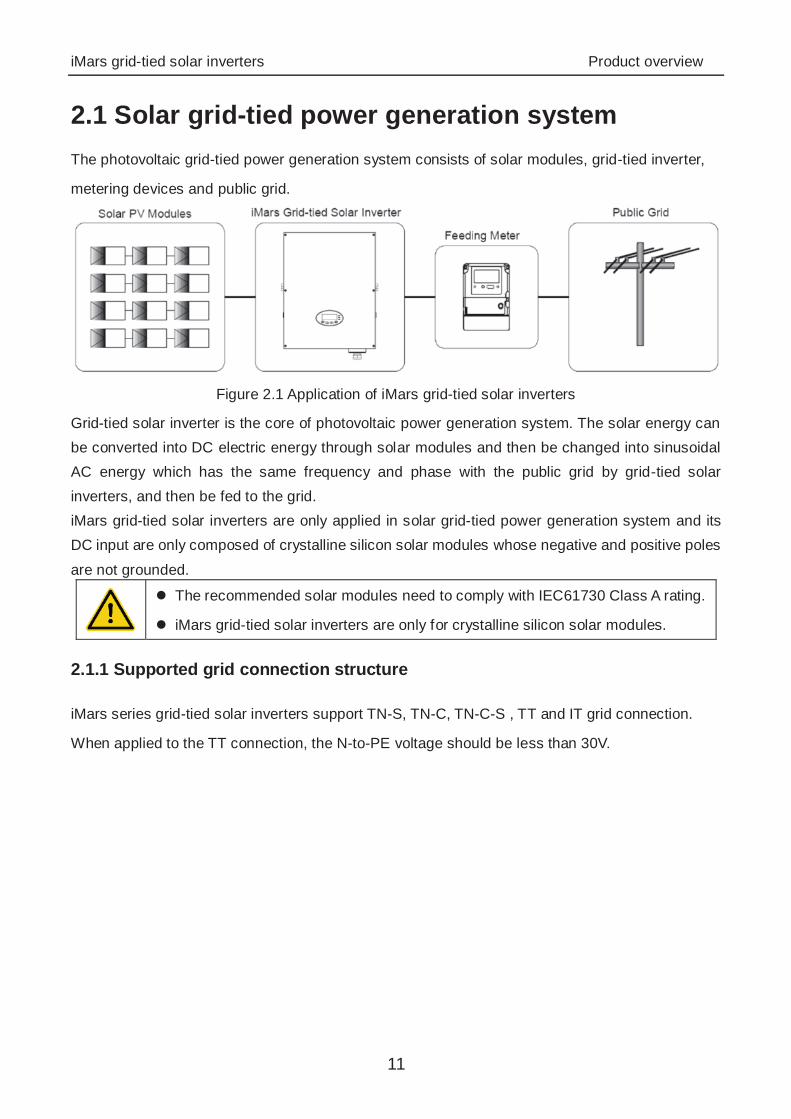
2.1 Solar grid-tied power generation system The photovoltaic grid-tied power generation system consists of solar modules, grid-tied inverter,
metering devices and public grid.
Figure 2.1 Application of iMars grid-tied solar inverters
Grid-tied solar inverter is the core of photovoltaic power generation system. The solar energy can be converted into DC electric energy through solar modules and then be changed into sinusoidal AC energy which has the same frequency and phase with the public grid by grid-tied solar inverters, and then be fed to the grid.iMars grid-tied solar inverters are only applied in solar grid-tied power generation system and its DC input are only composed of crystalline silicon solar modules whose negative and positive poles
are not grounded.
The recommended solar modules need to comply with IEC61730 Class A rating. iMars grid-tied solar inverters are only for crystalline silicon solar modules.
2.1.1 Supported grid connection structure
iMars series grid-tied solar inverters support TN-S, TN-C, TN-C-S , TT and IT grid connection.
When applied to the TT connection, the N-to-PE voltage should be less than 30V.
iMars grid-tied solar inverters Product overview
12
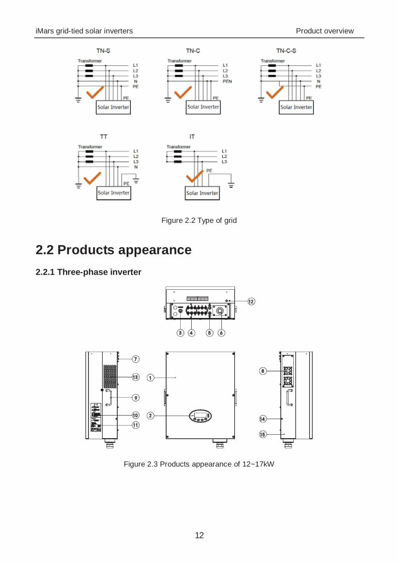
Figure 2.2 Type of grid
2.2 Products appearance 2.2.1 Three-phase inverter
Figure 2.3 Products appearance of 12~17kW
iMars grid-tied solar inverters Product overview
13
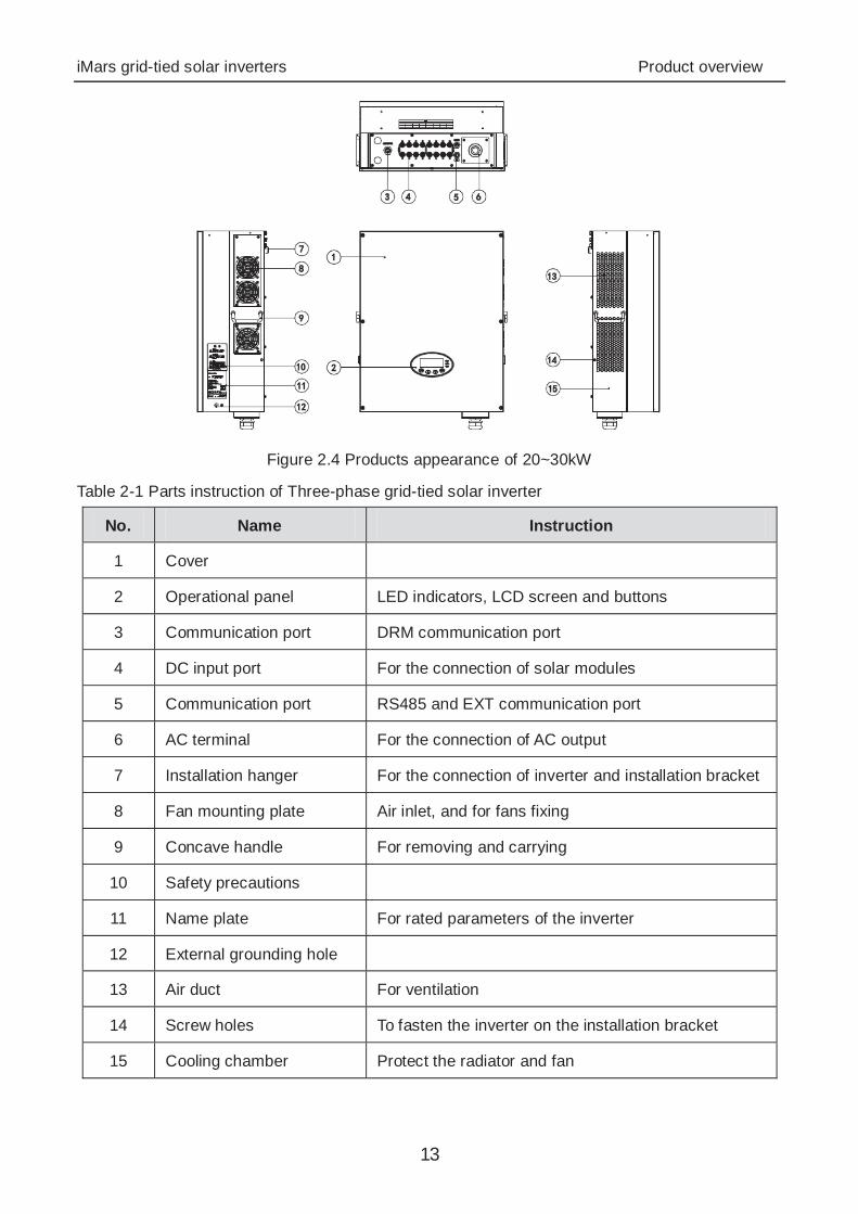
Figure 2.4 Products appearance of 20~30kW
Table 2-1 Parts instruction of Three-phase grid-tied solar inverter
No. Name Instruction
1 Cover
2 Operational panel LED indicators, LCD screen and buttons
3 Communication port DRM communication port
4 DC input port For the connection of solar modules
5 Communication port RS485 and EXT communication port
6 AC terminal For the connection of AC output
7 Installation hanger For the connection of inverter and installation bracket
8 Fan mounting plate Air inlet, and for fans fixing
9 Concave handle For removing and carrying
10 Safety precautions
11 Name plate For rated parameters of the inverter
12 External grounding hole
13 Air duct For ventilation
14 Screw holes To fasten the inverter on the installation bracket
15 Cooling chamber Protect the radiator and fan
iMars grid-tied solar inverters Product overview
14
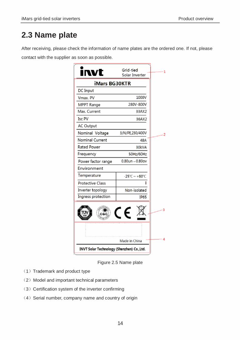
2.3 Name plate After receiving, please check the information of name plates are the ordered one. If not, please
contact with the supplier as soon as possible.
Figure 2.5 Name plate
1 Trademark and product type
2 Model and important technical parameters
3 Certification system of the inverter confirming
4 Serial number, company name and country of origin
iMars grid-tied solar inverters Product overview
15
Icons Instruction
TUV certification mark. The inverter is certified by TUV.
CE certification mark. The inverter complies with the CE directive.
CQC certification mark. The inverter is certified by CQC.
EU WEEE mark. Cannot dispose of the inverter as household waste.
2.4 DRM instruction
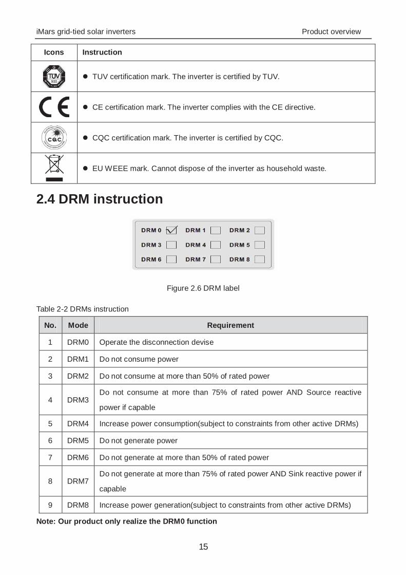
Figure 2.6 DRM label
Table 2-2 DRMs instruction
No. Mode Requirement
1 DRM0 Operate the disconnection devise
2 DRM1 Do not consume power
3 DRM2 Do not consume at more than 50% of rated power
4 DRM3 Do not consume at more than 75% of rated power AND Source reactive
power if capable
5 DRM4 Increase power consumption(subject to constraints from other active DRMs)
6 DRM5 Do not generate power
7 DRM6 Do not generate at more than 50% of rated power
8 DRM7 Do not generate at more than 75% of rated power AND Sink reactive power if
capable
9 DRM8 Increase power generation(subject to constraints from other active DRMs)
Note: Our product only realize the DRM0 function
iMars grid-tied solar inverters Product overview
16
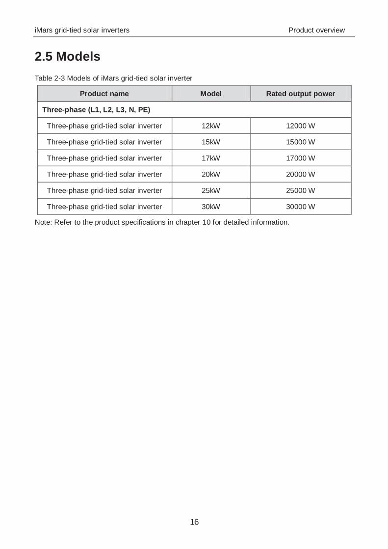
2.5 Models Table 2-3 Models of iMars grid-tied solar inverter
Product name Model Rated output power
Three-phase (L1, L2, L3, N, PE)
Three-phase grid-tied solar inverter 12kW 12000 W
Three-phase grid-tied solar inverter 15kW 15000 W
Three-phase grid-tied solar inverter 17kW 17000 W
Three-phase grid-tied solar inverter 20kW 20000 W
Three-phase grid-tied solar inverter 25kW 25000 W
Three-phase grid-tied solar inverter 30kW 30000 W
Note: Refer to the product specifications in chapter 10 for detailed information.

iMars grid-tied solar inverters Product overview
17
2.6 Dimensions and weight
Figure 2.7 Inverter dimensions
Table 2-4 Inverter dimension and net weight
Model H
(mm) W
(mm) D
(mm) Net weight
(kg)
12kW / 15kW/ 17kW 610 480 230 36
20kW / 25kW / 30kW 660 520 250 53
WH
D
Figure 2.8 Paper packages dimension
Table 2-5 Packages dimension and gross weight
Model H
(mm) W
(mm) D
(mm) Gross weight
(kg) Packaging Material
12kW / 15kW/ 17kW 788 622 396 43 Paper
20kW / 25kW / 30kW 850 665 410 62 Paper
iMars grid-tied solar inverters Storage
18
3 Storage If the inverter is not put into use immediately, the storage of inverter should meet the following
requirements:
Do not remove the outer packing.
The inverter needs to be stored in a clean and dry place, and prevent the erosion of dust and
water vapor.
The storage temperature should be kept at -40°C~+70°C, and the relative humidity should
be kept at 5%RH~95%RH.
The stacking of inverters is recommended to be placed according to the number of stacking
layers in the original shipment. Place the inverter carefully during stacking to avoid personal
injury or equipment damage caused by the falling of equipment.
Keep away from chemically corrosive substances that may corrode the inverter.
Periodic inspections are required. If damages are found by worms and rats, or packaging are
found to be damaged, the packaging materials must be replaced in time.
After long-term storage, inverters need to be inspected and tested by qualified personnel before
put into use.
iMars grid-tied solar inverters Installation
19
4 Installation This chapter describes how to install the inverter and connect it to the grid-tied solar system
(including the connection between solar modules, public grid and inverter).
Read this chapter carefully and ensure all installation requirements are met before installation.
Only qualified electricians are allowed to install the inverter.
iMars grid-tied solar inverters Installation
20
4.1 Unpacking inspection I Inspect the information of the order and the name plate to ensure the product are the ordered one
and no damage to the package. If any problem, contact the supplier as soon as possible.
Put the inverter into the package if not used and protect it from humidity and dust.
Check as following after unpacking:
(1) Ensure no damage to the inverter unit.
(2) Ensure the operation manual, port and installation accessories in the package.
(3) Ensure no damage or loss to the items in the package.
(4) Ensure the information of the order are the same as that of the name plate.
Below are the detailed lists:
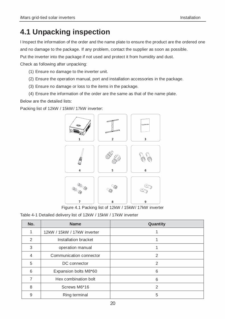
Packing list of 12kW / 15kW/ 17kW inverter:
Figure 4.1 Packing list of 12kW / 15kW/ 17kW inverter
Table 4-1 Detailed delivery list of 12kW / 15kW / 17kW inverter
No. Name Quantity
1 12kW / 15kW / 17kW inverter 1
2 Installation bracket 1
3 operation manual 1
4 Communication connector 2
5 DC connector 2
6 Expansion bolts M8*60 6
7 Hex combination bolt 6
8 Screws M6*16 2
9 Ring terminal 5
iMars grid-tied solar inverters Installation
21
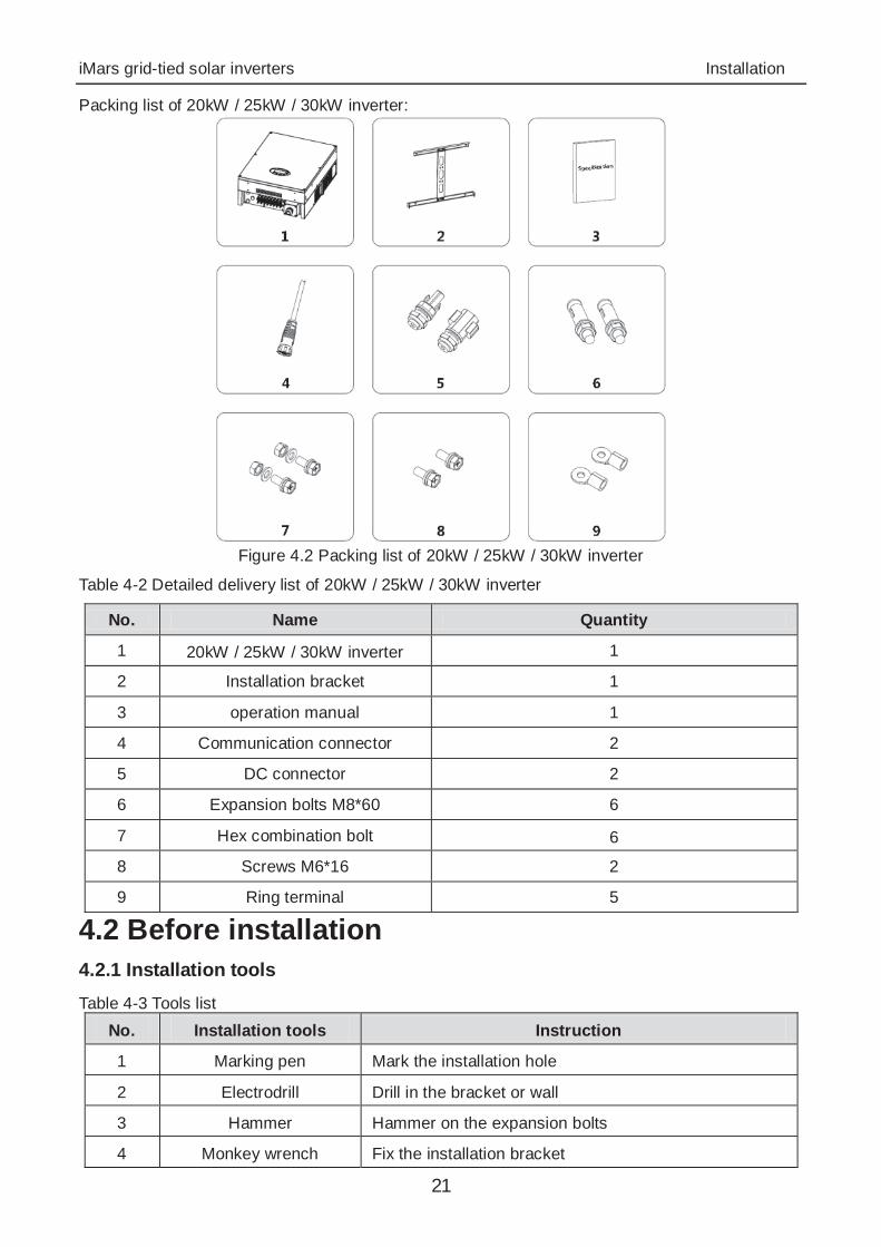
Packing list of 20kW / 25kW / 30kW inverter:
Figure 4.2 Packing list of 20kW / 25kW / 30kW inverter
Table 4-2 Detailed delivery list of 20kW / 25kW / 30kW inverter
No. Name Quantity
1 20kW / 25kW / 30kW inverter 1
2 Installation bracket 1
3 operation manual 1
4 Communication connector 2
5 DC connector 2
6 Expansion bolts M8*60 6
7 Hex combination bolt 6
8 Screws M6*16 2
9 Ring terminal 5
4.2 Before installation 4.2.1 Installation tools Table 4-3 Tools list
No. Installation tools Instruction
1 Marking pen Mark the installation hole
2 Electrodrill Drill in the bracket or wall
3 Hammer Hammer on the expansion bolts
4 Monkey wrench Fix the installation bracket
iMars grid-tied solar inverters Installation
22
No. Installation tools Instruction
5 Allen driver Fasten the screws, remove and install AC wiring box
6 Straight screwdriver For AC wiring
7 Megger Measuring insulation performance and impedance
8 Multimeter Check the circuit and AC and DC voltage
9 Electric iron Weld communications cable
10 Wire crimper Crimp DC terminals
11 Hydraulic clamp Crimp ring terminal for AC wiring
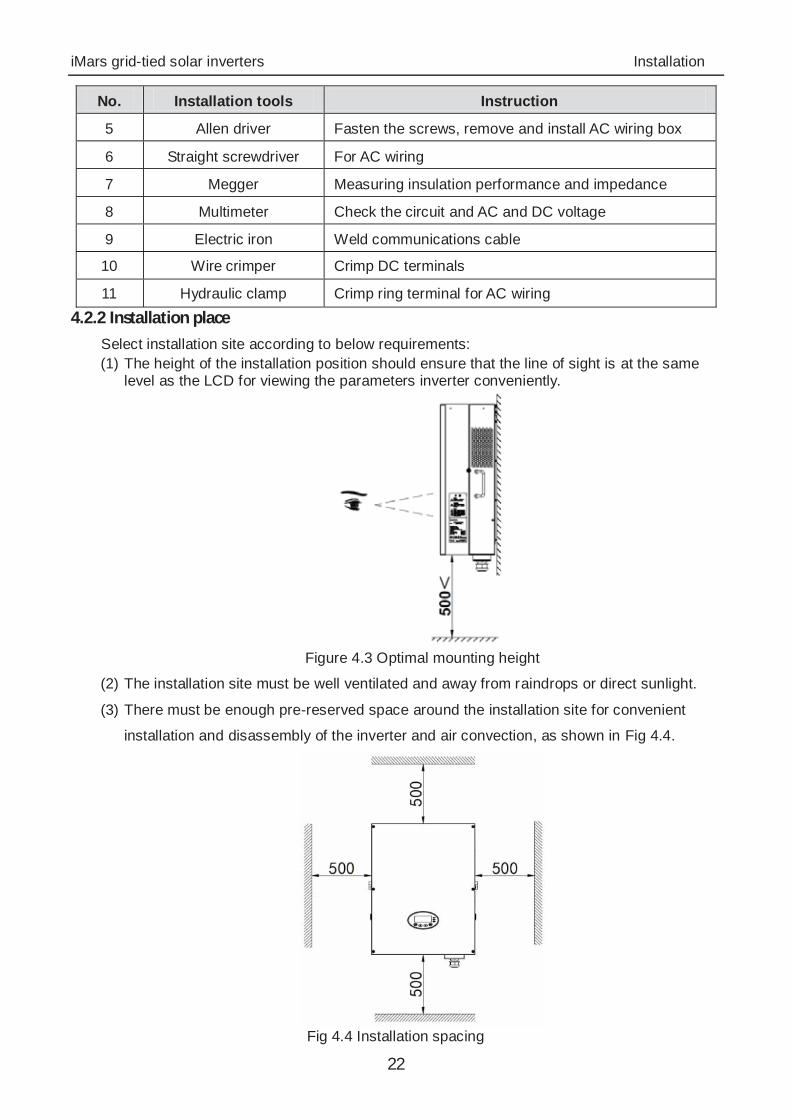
4.2.2 Installation place Select installation site according to below requirements: (1) The height of the installation position should ensure that the line of sight is at the same
level as the LCD for viewing the parameters inverter conveniently.
Figure 4.3 Optimal mounting height
(2) The installation site must be well ventilated and away from raindrops or direct sunlight.
(3) There must be enough pre-reserved space around the installation site for convenient
installation and disassembly of the inverter and air convection, as shown in Fig 4.4.
Fig 4.4 Installation spacing

iMars grid-tied solar inverters Installation
23
When install more than one inverter, it is necessary to reserve a certain space between the
inverters. The left and right spacing is shown as Figure 4.5, and the upper and lower sides of the
inverter should have sufficient space to ensure good heat dissipation.
Figure 4.5 Side-by-side installation space requirements
(4) The ambient temperature of installation should be -25°C~60°C
(5) The installation site should be away from electronic devices which can generate strong
electromagnetic interference
(6) The inverter should be installed on firm and solid surface eg wall surface and metal
bracket
(7) The installation surface should be vertical to the horizontal line, as shown in Figure 4.6
Install the inverter vertically or backward 15 to facilitate heat dissipation.
Do not tilt the inverter forward, horizontal, upside down, over- backward, and roll when install the
inverter.
Fig 4.6 Installation position of the inverter
iMars grid-tied solar inverters Installation
24
(8) The installation should ensure that the inverter is reliably grounded, and the material of
grounded metal conductor should be consistent with the metal material reserved for the
grounding of the inverter.
Do not remove any part and component of the inverter unintended; otherwise
damage to the device and physical injury may occur. 4.2.3 Connection cables
The user can select connection cable according the table below: Table 4-4 Cable specifications
Model
DC side AC side
Cross-section (length ≤50m) mm
Cross-section (length >50m) mm
Mini cross-section mm
L N/PE
12kW /15kW / 17kW 4 6 6 4
20kW / 25kW 4 6 8 4
30kW 4 6 10 6
4.2.4 Miniature circuit breakers
It is recommended strongly to install circuit breakers or fuses at the DC input and AC output to ensure safe installation and running.
In order to protect the PCE, user and installer, external DC and AC circuit breaker shall be equipped at the end-use application;
The wiring shall be according local electric code. Choose proper cable for power input and output lines. Input and output cable shall be PV private cables suitable for outdoor use.
Table 4-5 Breakers specifications
Model DC input AC output
Recommended DC breakers (optional for length >100m)
Recommended AC breakers
12kW DC1000V, C32A, 2P AC400V, C25A, 4P
15kW DC1000V, C32A, 2P AC400V, C32A, 4P
17kW DC1000V, C32A, 2P AC400V, C35A, 4P
20kW DC1000V, C40A, 2P AC400V, C50A, 4P
25kW DC1000V, C40A, 2P AC400V, C63A, 4P
30kW DC1000V, C50A, 2P AC400V, C63A, 4P
iMars grid-tied solar inverters Installation
25
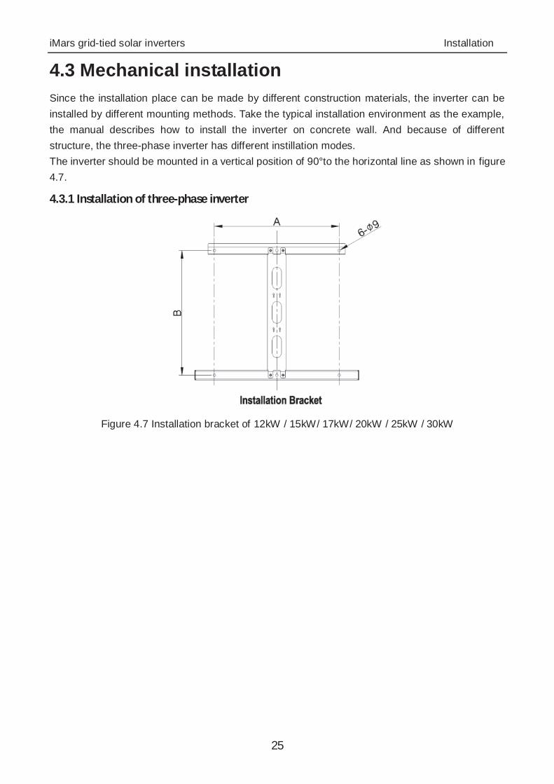
4.3 Mechanical installation Since the installation place can be made by different construction materials, the inverter can be installed by different mounting methods. Take the typical installation environment as the example, the manual describes how to install the inverter on concrete wall. And because of different structure, the three-phase inverter has different instillation modes. The inverter should be mounted in a vertical position of 90°to the horizontal line as shown in figure 4.7.
4.3.1 Installation of three-phase inverter
Figure 4.7 Installation bracket of 12kW / 15kW/ 17kW/ 20kW / 25kW / 30kW
iMars grid-tied solar inverters Installation
26
Table 4-6 Instruction of installation bracket
Model Installation hole
A(mm) B(mm)
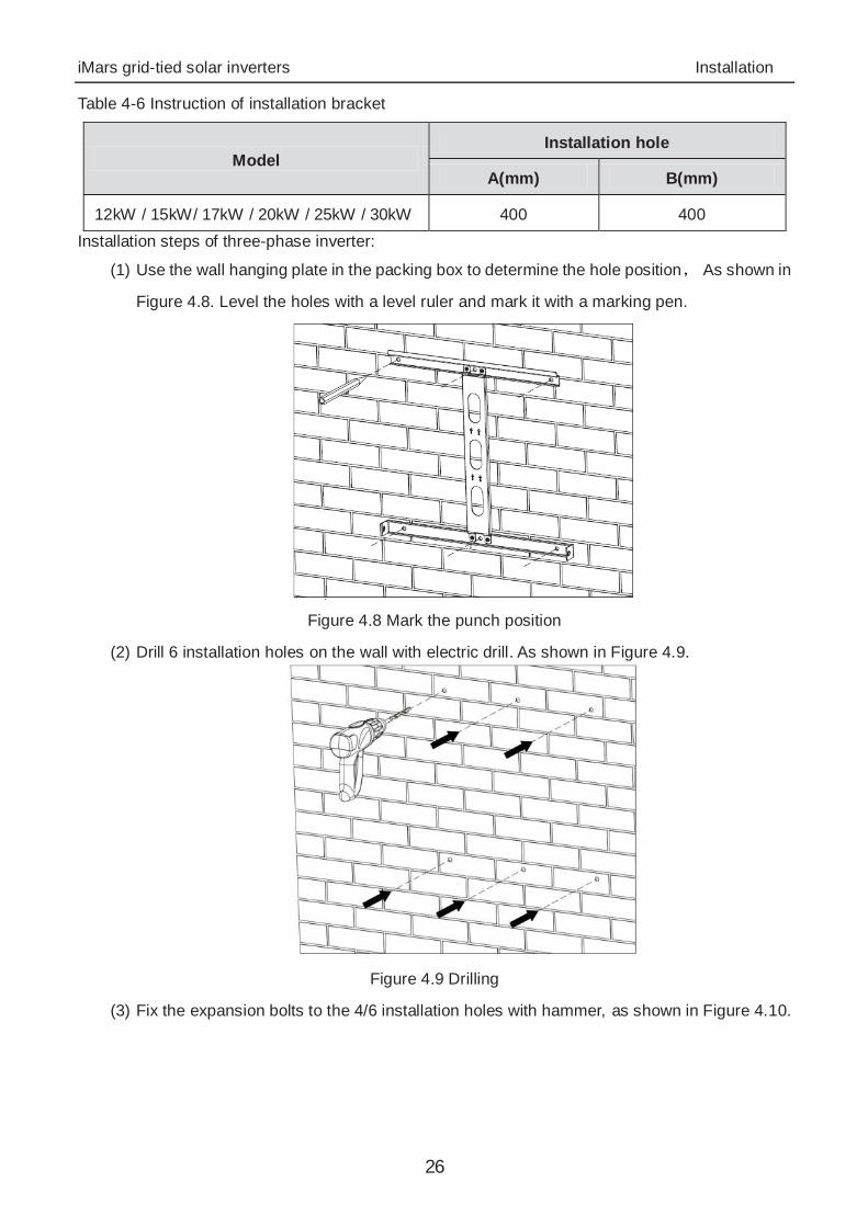
12kW / 15kW/ 17kW / 20kW / 25kW / 30kW 400 400 Installation steps of three-phase inverter:
(1) Use the wall hanging plate in the packing box to determine the hole position As shown in
Figure 4.8. Level the holes with a level ruler and mark it with a marking pen.
Figure 4.8 Mark the punch position
(2) Drill 6 installation holes on the wall with electric drill. As shown in Figure 4.9.
Figure 4.9 Drilling
(3) Fix the expansion bolts to the 4/6 installation holes with hammer, as shown in Figure 4.10.
iMars grid-tied solar inverters Installation
27
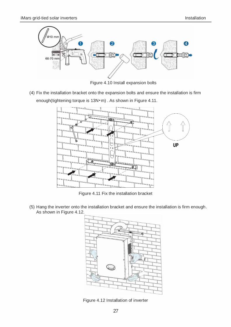
Figure 4.10 Install expansion bolts
(4) Fix the installation bracket onto the expansion bolts and ensure the installation is firm
enough(tightening torque is 13N m) . As shown in Figure 4.11.
Figure 4.11 Fix the installation bracket
(5) Hang the inverter onto the installation bracket and ensure the installation is firm enough.
As shown in Figure 4.12.
Figure 4.12 Installation of inverter
iMars grid-tied solar inverters Installation
28
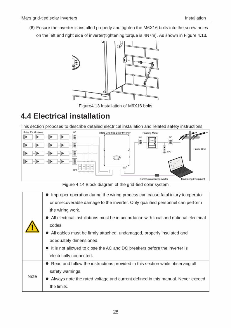
(6) Ensure the inverter is installed properly and tighten the M6X16 bolts into the screw holes
on the left and right side of inverter(tightening torque is 4N m). As shown in Figure 4.13.
Figure4.13 Installation of M6X16 bolts
4.4 Electrical installation This section proposes to describe detailed electrical installation and related safety instructions.
Figure 4.14 Block diagram of the grid-tied solar system
Improper operation during the wiring process can cause fatal injury to operator
or unrecoverable damage to the inverter. Only qualified personnel can perform
the wiring work.
All electrical installations must be in accordance with local and national electrical
codes.
All cables must be firmly attached, undamaged, properly insulated and
adequately dimensioned.
It is not allowed to close the AC and DC breakers before the inverter is
electrically connected.
Note
Read and follow the instructions provided in this section while observing all
safety warnings.
Always note the rated voltage and current defined in this manual. Never exceed
the limits.
iMars grid-tied solar inverters Installation
29
4.4.1 Connection of solar modules
5
1 1
2
2
2
2 3 3
4 45
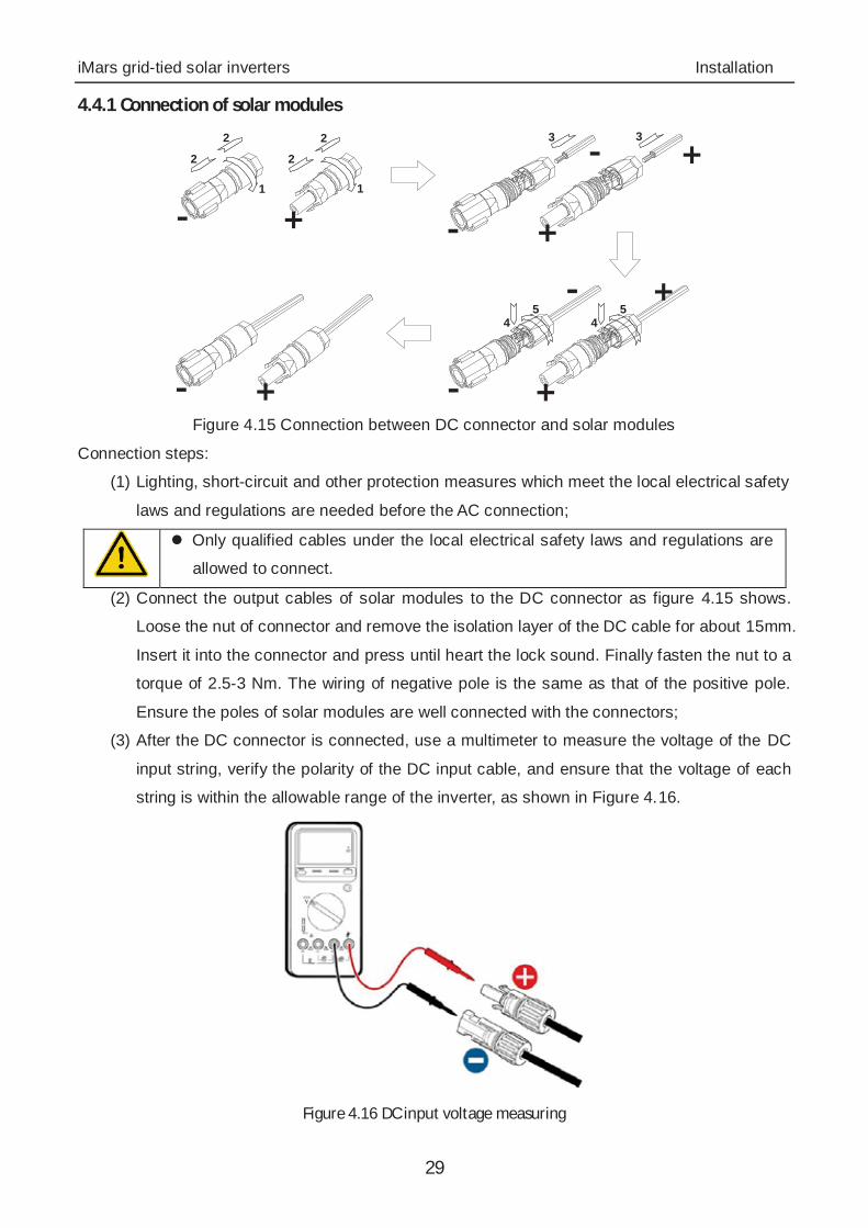
Figure 4.15 Connection between DC connector and solar modules
Connection steps:
(1) Lighting, short-circuit and other protection measures which meet the local electrical safety
laws and regulations are needed before the AC connection;
Only qualified cables under the local electrical safety laws and regulations are
allowed to connect.
(2) Connect the output cables of solar modules to the DC connector as figure 4.15 shows.
Loose the nut of connector and remove the isolation layer of the DC cable for about 15mm.
Insert it into the connector and press until heart the lock sound. Finally fasten the nut to a
torque of 2.5-3 Nm. The wiring of negative pole is the same as that of the positive pole.
Ensure the poles of solar modules are well connected with the connectors;
(3) After the DC connector is connected, use a multimeter to measure the voltage of the DC
input string, verify the polarity of the DC input cable, and ensure that the voltage of each
string is within the allowable range of the inverter, as shown in Figure 4.16.
Figure 4.16 DC input voltage measuring
iMars grid-tied solar inverters Installation
30
The solar modules connected with the inverter needs to be the configured ones
other than some connecting devices without authorized. Otherwise, device
damage, unstable operation or fire may occur.
(4) Connect the DC connector with the inverter and ensure tightly-fastened;
(5) Insert the screw-driver into the hole of the connector to remove the connector form the
inverter.
(6) Unclench the pressed cover with screw-driver to remove the cables from the connector.
4.4.2 AC connection of 12kW / 15kW / 17kW / 20kW / 25kW / 30kW inverter
Table4-7 Port instruction of12kW / 15kW/ 17kW /20kW / 25kW / 30kW AC connector
AC connector Three-phase Remark
L1 L1 (A)
L2 L2 (B)
L3 L3 (C)
N N neutral wire
PE grounding wire Must be connected
Connection steps of 12kW / 15kW/ 17kW / 20kW / 25kW / 30kW inverter:
(1)Lighting, short-circuit and other protection measures which meet the local electrical safety laws
and regulations are needed before the AC connection;
Only qualified cables under the local electrical safety laws and regulations are
allowed to connect.
Only with the permission of the local electric power company can the inverter be
connected to the utility grid.
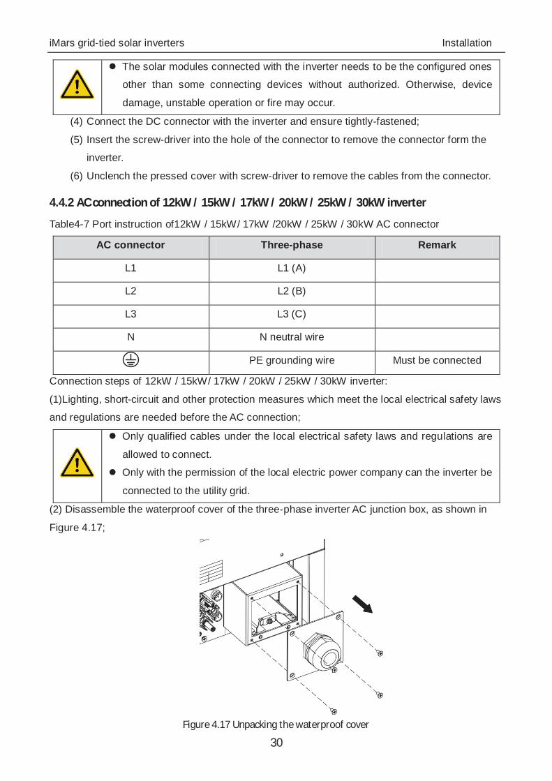
(2) Disassemble the waterproof cover of the three-phase inverter AC junction box, as shown in
Figure 4.17;
Figure 4.17 Unpacking the waterproof cover
iMars grid-tied solar inverters Installation
31
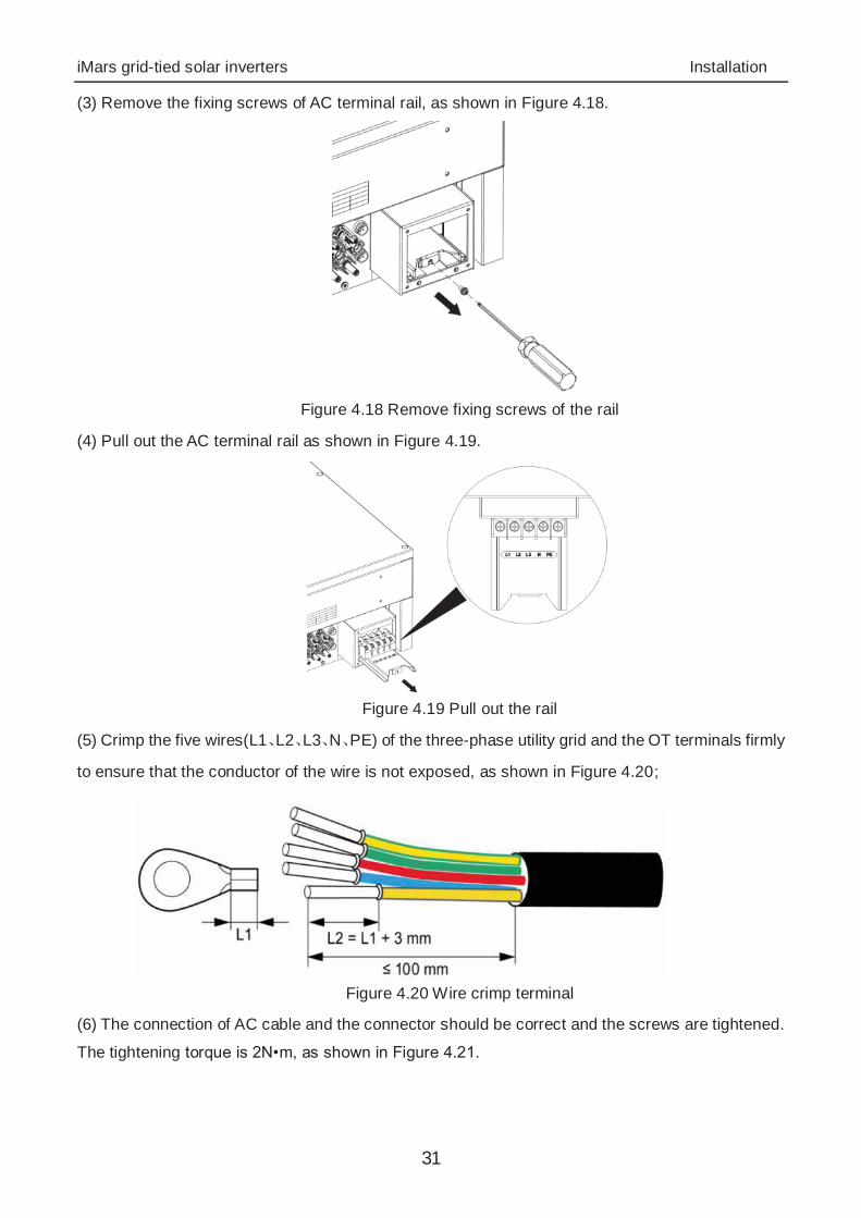
(3) Remove the fixing screws of AC terminal rail, as shown in Figure 4.18.
Figure 4.18 Remove fixing screws of the rail
(4) Pull out the AC terminal rail as shown in Figure 4.19.
Figure 4.19 Pull out the rail
(5) Crimp the five wires(L1 L2 L3 N PE) of the three-phase utility grid and the OT terminals firmly
to ensure that the conductor of the wire is not exposed, as shown in Figure 4.20;
Figure 4.20 Wire crimp terminal
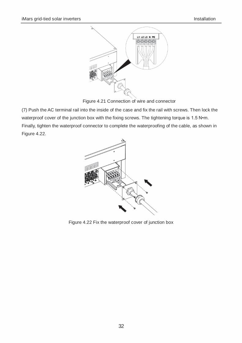
(6) The connection of AC cable and the connector should be correct and the screws are tightened.
The tightening torque is 2N•m, as shown in Figure 4.21.
iMars grid-tied solar inverters Installation
32
Figure 4.21 Connection of wire and connector
(7) Push the AC terminal rail into the inside of the case and fix the rail with screws. Then lock the
waterproof cover of the junction box with the fixing screws. The tightening torque is 1.5 N•m.
Finally, tighten the waterproof connector to complete the waterproofing of the cable, as shown in
Figure 4.22.
Figure 4.22 Fix the waterproof cover of junction box
iMars grid-tied solar inverters Operation
33
5 Operation This chapter describes detailed operation of the inverter which involves the inspection before
operation, grid-tied operation, stopping and daily maintenance of the inverter.
iMars grid-tied solar inverters Operation
34
5.1 Inspection before operation Check as follows before operation (including but not limited to):
(1) Ensure the installation site meet the requirement mentioned in section 4.2.2 for easy
installation, removing, operation and maintenance;
(2) Ensure the mechanical installation meet the requirement mentioned in section 4.3;
(3) Ensure the electrical installation meet the requirement mentioned in section 4.4;
(4) Ensure all switches are “off”;
(5) Ensure the voltage meet the requirement mentioned in chapter 10;
(6) Ensure all electrical safety precautions are clearly-identified on the installation site.
Do check as above before any operation if the system or inverter needs to be
installed, refitted and maintained.
5.2 Grid-tied operation
Note
When power on the inverter for the first time, please refer to section 6.5 to
complete grid certification choice.
Keep the inverter power on at least 30 minutes to charge for the internal clock
battery.
Please start the inverter as follows:
(1) Ensure the requirements mentioned in section 5.1 are met;
(2) Switch on the breakers at the AC side;
(3) Switch on the integrated DC switch;
(4) Switch on the switch on the DC side;
(5) Observe the LED indicators and information displayed on the screen. Refer to chapter 6
for detailed information.
(6) Run Green indicator blinks, others off: the inverter is power on and in
self-inspection;
(7) Run Green indicator on, others off: the inverter is in power generation after
self-inspection----successful commissioning.
(8) “Warn” or “Fault” indicators are on or blinking: the inverter is power on, but fault
occurs. Please refer to section 6.3 for detailed information, and then stop as the
section 5.3 mentioned, finally settle the problems as chapter 8. If all faults are solved,
do as chapter 5 mentioned.
(9) Refer t o section 6.4.4 to set the inverter time according to local time.
(10) The default DC input mode is “independent”. Please refer to section 6.4.4 for inquiry
and detailed setting.
iMars grid-tied solar inverters Operation
35
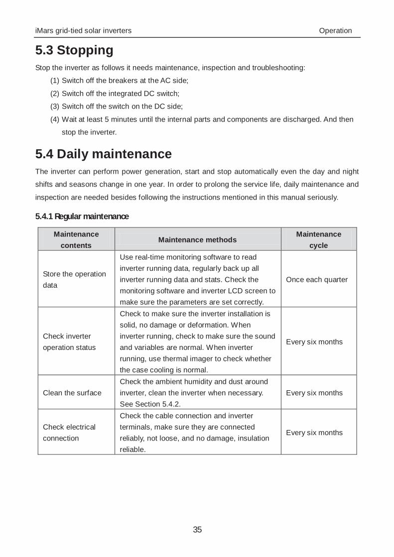
5.3 Stopping Stop the inverter as follows it needs maintenance, inspection and troubleshooting:
(1) Switch off the breakers at the AC side;
(2) Switch off the integrated DC switch;
(3) Switch off the switch on the DC side;
(4) Wait at least 5 minutes until the internal parts and components are discharged. And then
stop the inverter.
5.4 Daily maintenance The inverter can perform power generation, start and stop automatically even the day and night
shifts and seasons change in one year. In order to prolong the service life, daily maintenance and
inspection are needed besides following the instructions mentioned in this manual seriously.
5.4.1 Regular maintenance
Maintenance contents
Maintenance methods Maintenance
cycle
Store the operation data
Use real-time monitoring software to read inverter running data, regularly back up all inverter running data and stats. Check the monitoring software and inverter LCD screen to make sure the parameters are set correctly.
Once each quarter
Check inverter operation status
Check to make sure the inverter installation is solid, no damage or deformation. When inverter running, check to make sure the sound and variables are normal. When inverter running, use thermal imager to check whether the case cooling is normal.
Every six months
Clean the surface Check the ambient humidity and dust around inverter, clean the inverter when necessary. See Section 5.4.2.
Every six months
Check electrical connection
Check the cable connection and inverter terminals, make sure they are connected reliably, not loose, and no damage, insulation reliable.
Every six months
iMars grid-tied solar inverters Operation
36
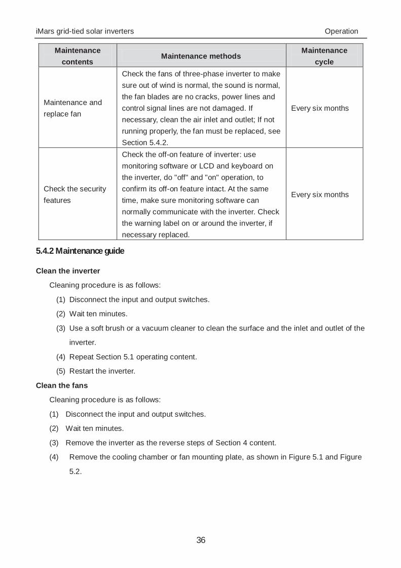
Maintenance contents
Maintenance methods Maintenance
cycle
Maintenance and replace fan
Check the fans of three-phase inverter to make sure out of wind is normal, the sound is normal, the fan blades are no cracks, power lines and control signal lines are not damaged. If necessary, clean the air inlet and outlet; If not running properly, the fan must be replaced, see Section 5.4.2.
Every six months
Check the security features
Check the off-on feature of inverter: use monitoring software or LCD and keyboard on the inverter, do "off" and "on" operation, to confirm its off-on feature intact. At the same time, make sure monitoring software can normally communicate with the inverter. Check the warning label on or around the inverter, if necessary replaced.
Every six months
5.4.2 Maintenance guide
Clean the inverter
Cleaning procedure is as follows:
(1) Disconnect the input and output switches.
(2) Wait ten minutes.
(3) Use a soft brush or a vacuum cleaner to clean the surface and the inlet and outlet of the
inverter.
(4) Repeat Section 5.1 operating content.
(5) Restart the inverter.
Clean the fans
Cleaning procedure is as follows:
(1) Disconnect the input and output switches.
(2) Wait ten minutes.
(3) Remove the inverter as the reverse steps of Section 4 content.
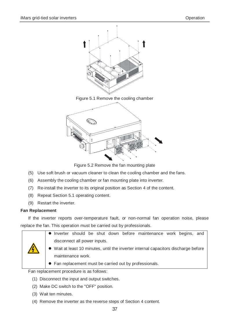
(4) Remove the cooling chamber or fan mounting plate, as shown in Figure 5.1 and Figure
5.2.
iMars grid-tied solar inverters Operation
37
Figure 5.1 Remove the cooling chamber
Figure 5.2 Remove the fan mounting plate
(5) Use soft brush or vacuum cleaner to clean the cooling chamber and the fans.
(6) Assembly the cooling chamber or fan mounting plate into inverter.
(7) Re-install the inverter to its original position as Section 4 of the content.
(8) Repeat Section 5.1 operating content.
(9) Restart the inverter.
Fan Replacement
If the inverter reports over-temperature fault, or non-normal fan operation noise, please
replace the fan. This operation must be carried out by professionals.
Inverter should be shut down before maintenance work begins, and
disconnect all power inputs.
Wait at least 10 minutes, until the inverter internal capacitors discharge before
maintenance work.
Fan replacement must be carried out by professionals.
Fan replacement procedure is as follows:
(1) Disconnect the input and output switches.
(2) Make DC switch to the "OFF" position.
(3) Wait ten minutes.
(4) Remove the inverter as the reverse steps of Section 4 content.

iMars grid-tied solar inverters Operation
38
(5) Dismantle the fan mounting plate as shown in Figure 5.2.
(6) Remove the damaged fans, and replace good fans, connect the power lines and control
signal lines, as shown in Figure 5.3.
Figure 5.3 Replace fans
(7) Assembly the cooling chamber or fan mounting plate into inverter.
(8) Re-install the inverter to its original position as Section 4 of the content.
(9) Repeat Section 5.1 operating content.
(10) Restart the inverter.
Note Once the inverter alarms and stops, do not be restarted before all the fault has
been ruled out. Checks should be strictly in accordance with Section 5.1 steps.
iMars grid-tied solar inverters Display panel
39
6 Display panel This chapter describes the panel displaying and how to operate on the panel, which involves the
LCD display, LED indicators and operation panel.
iMars grid-tied solar inverters Display panel
40
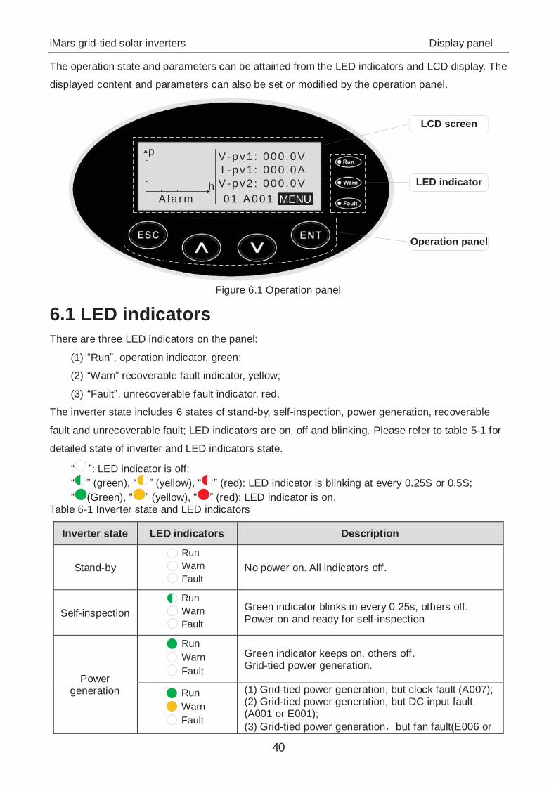
The operation state and parameters can be attained from the LED indicators and LCD display. The
displayed content and parameters can also be set or modified by the operation panel.
LED indicator
LCD screen
Operation panel
V-pv1 : 000 .0VI -pv1 : 000 .0AV-pv2 : 000 .0V01 .A001 MENUAla rm
p
h
Figure 6.1 Operation panel
6.1 LED indicators There are three LED indicators on the panel:
(1) “Run”, operation indicator, green;
(2) “Warn” recoverable fault indicator, yellow;
(3) “Fault”, unrecoverable fault indicator, red.
The inverter state includes 6 states of stand-by, self-inspection, power generation, recoverable
fault and unrecoverable fault; LED indicators are on, off and blinking. Please refer to table 5-1 for
detailed state of inverter and LED indicators state.
“ ”: LED indicator is off; “ ” (green), “ ” (yellow), “ ” (red): LED indicator is blinking at every 0.25S or 0.5S; “ (Green), “ ” (yellow), “ ” (red): LED indicator is on.
Table 6-1 Inverter state and LED indicators
Inverter state LED indicators Description
Stand-by RunWarnFault
No power on. All indicators off.
Self-inspection RunWarnFault
Green indicator blinks in every 0.25s, others off. Power on and ready for self-inspection
Power generation
RunWarnFault
Green indicator keeps on, others off. Grid-tied power generation.
RunWarnFault
(1) Grid-tied power generation, but clock fault (A007); (2) Grid-tied power generation, but DC input fault (A001 or E001); (3) Grid-tied power generation but fan fault(E006 or

iMars grid-tied solar inverters Display panel
41
Inverter state LED indicators Description E012); Green and yellow indicator keeps on, others off.
Recoverable fault
RunWarnFault
Inverter stand-by. The public grid fault(A001, A003, A004, A005or A006); Yellow indicator blinks in every 0.5s, others off
RunWarnFault
(1) Inverter stand-by. Temperature abnormal(E006); (2) Inverter stand-by. DC input fault (E001); Yellow indicator keeps on, others off
Unrecoverable fault
RunWarnFault
Hardware or software fault (E003, E004, E005, E008, E009, E011, E013 or E015). De-couple the inverter from the system before maintenance. Red indicator blinks in every 0.5s, others off
RunWarnFault
Current-leakage or unqualified output power energy of the inverter (E007, E010, E014, E017, E018 or E020). De-couple the inverter from the system before maintenance. Red indicator keeps on, others off
Artificial turned off
RunWarnFault
Stop after the communication or panel command. All indicators are on.
Note Please refer to chapter 6 and 8 for detailed fault information and troubleshooting.
6.2 Operation panel There are 4 buttons on the panel:
(1) “ESC”, exit and return ; (2) “ ”, back to the front page and data increasing; (3) “ ” to the next page and data decreasing; (4) “ENT”, enter.
6.3 LCD screen All information is displayed on the LCD screen. The background illumination of LCD screen will go
out to save power if there is not button operation in 15 seconds. But it can be activated by pressing
any button. Press “ENT” to enter into the main interface if the background illumination is on. All
parameters can be viewed and set on the interface.
There are main interface and menu interfaces on the LCD screen, of which the main interface is
the default one after power on, while the menu interfaces are used to watch and set parameters or
other manual operation, such as viewing the monitoring parameters, history record, system
information, statistics and fault information and setting the displayed language, time,
communication address, password and factory defaults.

iMars grid-tied solar inverters Display panel
42
Text ParameterDisplay Area
Fault Code MenuStatus Area
Curve GraphicDisplay Area
Figure 6.2 Main interface
The main interface of the LCD screen is shown as the figure above: (1) The curve displays the power changing at the current day; (2) The words on the screen display the current key parameters of the inverter. Three lines of
words are displayed at a time, but if the inverter is in operation or stand-by state, the words are rolling forward at every 3s. And the user can press “ ” or “ ” to look up the information freely;
(3) 5 states of the inverter are displayed on the screen; (4) If the inverter is in fault or warning state, up to 8 corresponding fault codes can be
displaying on the screen.
6.4 Functions operation Most of the parameters can be viewed and set through the LCD screen and operation panel.
M a i n M e n uM o n i t P a r a mH i s t o r yS t a t i s t i c s
S e t u pS y s t e m I n f oF a u l t I n f o
Figure 6.3 Main interface
6.4.1 Monitoring parameters
Press “ ” and “ ” in the main interface to select “Monit Param”, and then press “ENT” to view the parameters which is shown in figure 6.4. Go the front or next page through “ ” and “ ” and return through “ESC”.
C u r r e n t S t a t eE - t o d : 0 W h$ - t o d : 0 . 0 0P - i n : 0 . 0 0 k W
Figure 6.4 Monitoring parameters
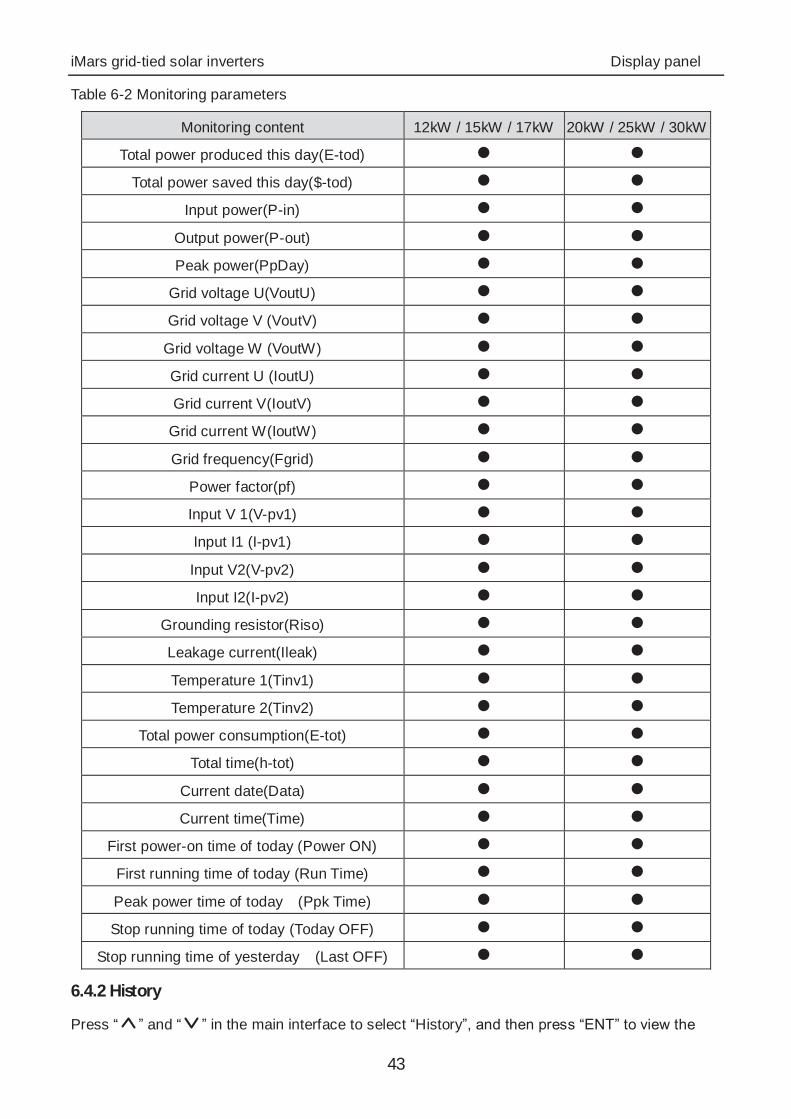
Different inverter has different parameters. “ ” in table 6-2 means the monitoring parameters of
the inverter can be displayed on the LCD screen.
iMars grid-tied solar inverters Display panel
43
Table 6-2 Monitoring parameters
Monitoring content 12kW / 15kW / 17kW 20kW / 25kW / 30kW
Total power produced this day(E-tod) ● ● Total power saved this day($-tod) ● ●
Input power(P-in) ● ● Output power(P-out) ● ● Peak power(PpDay) ● ●
Grid voltage U(VoutU) ● ● Grid voltage V (VoutV) ● ●
Grid voltage W (VoutW) ● ● Grid current U (IoutU) ● ● Grid current V(IoutV) ● ●
Grid current W(IoutW) ● ● Grid frequency(Fgrid) ● ●
Power factor(pf) ● ● Input V 1(V-pv1) ● ● Input I1 (I-pv1) ● ● Input V2(V-pv2) ● ● Input I2(I-pv2) ● ●
Grounding resistor(Riso) ● ● Leakage current(Ileak) ● ● Temperature 1(Tinv1) ● ● Temperature 2(Tinv2) ● ●
Total power consumption(E-tot) ● ● Total time(h-tot) ● ●
Current date(Data) ● ● Current time(Time) ● ●
First power-on time of today (Power ON) ● ● First running time of today (Run Time) ● ● Peak power time of today (Ppk Time) ● ● Stop running time of today (Today OFF) ● ●
Stop running time of yesterday (Last OFF) ● ● 6.4.2 History
Press “ ” and “ ” in the main interface to select “History”, and then press “ENT” to view the
iMars grid-tied solar inverters Display panel
44
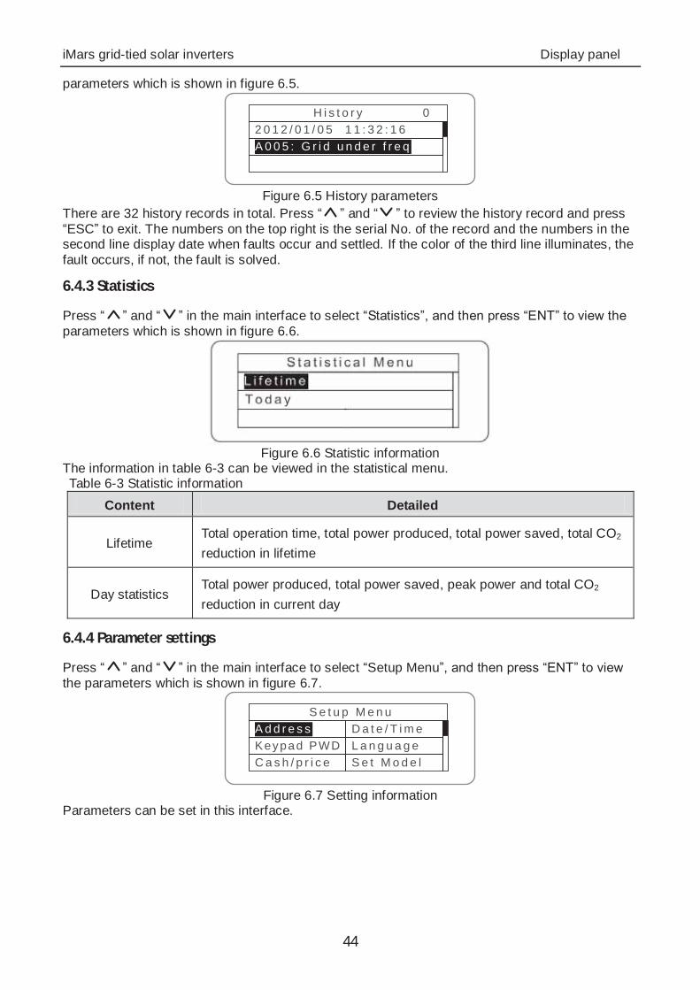
parameters which is shown in figure 6.5.
H i s t o r y 02 0 1 2 / 0 1 / 0 5 1 1 : 3 2 : 1 6A 0 0 5 : G r i d u n d e r f r e q
Figure 6.5 History parameters
There are 32 history records in total. Press “ ” and “ ” to review the history record and press “ESC” to exit. The numbers on the top right is the serial No. of the record and the numbers in the second line display date when faults occur and settled. If the color of the third line illuminates, the fault occurs, if not, the fault is solved.
6.4.3 Statistics
Press “ ” and “ ” in the main interface to select “Statistics”, and then press “ENT” to view the parameters which is shown in figure 6.6.
Figure 6.6 Statistic information
The information in table 6-3 can be viewed in the statistical menu. Table 6-3 Statistic information
Content Detailed
Lifetime Total operation time, total power produced, total power saved, total CO2 reduction in lifetime
Day statistics Total power produced, total power saved, peak power and total CO2 reduction in current day
6.4.4 Parameter settings
Press “ ” and “ ” in the main interface to select “Setup Menu”, and then press “ENT” to view the parameters which is shown in figure 6.7.
S e t u p M e n uA d d r e s sKeypad PWDC a s h / p r i c e
D a t e / T i m eL a n g u a g eS e t M o d e l
Figure 6.7 Setting information
Parameters can be set in this interface.
iMars grid-tied solar inverters Display panel
45
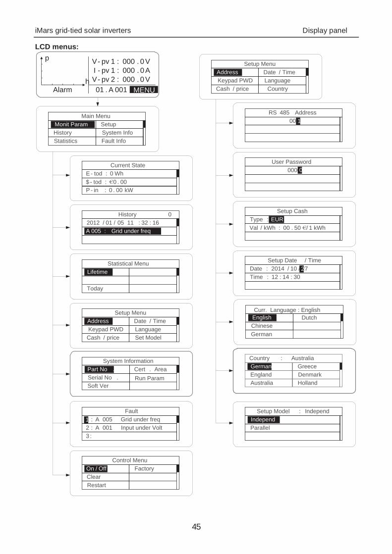
LCD menus:
Current StateE - tod : 0 Wh$ - tod : 0 . 00P - in : 0 . 00 kW
History 02012 / 01 / 05 11 : 32 : 16A 005 : Grid under freq
Statistical MenuLifetime
Today
Setup MenuAddressKeypad PWDCash / price
Date / TimeLanguageSet Model
Fault1 : A 005 Grid under freq2 : A 001 Input under Volt3 :
1
Control MenuOn / OffClearRestart
Factory
Setup MenuAddressKeypad PWDCash / price
Date / TimeLanguageCountry
RS 485 Address0011
User Password00000
Setup CashType : EURVal / kWh : 00 . 50 / 1 kWh
EUR
Setup Date / TimeDate : 2014 / 10 / 27Time : 12 : 14 : 30
2
Setup Model : IndependIndependParallel
Main MenuMonit ParamHistoryStatistics
SetupSystem InfoFault Info
V- pv 1 : 000 . 0 VI - pv 1 : 000 . 0 AV- pv 2 : 000 . 0 V01 . A 001Alarm
p
h
Curr. Language : EnglishEnglishChineseGerman
Dutch
Country : AustraliaGermanyEnglandAustralia
GreeceDenmarkHolland
MENU
System InformationPart No .Serial No .Soft Ver
Cert . AreaRun Param

iMars grid-tied solar inverters Display panel
46
Table 6-4 Parameters setting
Setting item LCD display Instruction
RS485 Address
R S 4 8 5 A d d r e s s0 0 11
Enter into the interface and edit the data through “ ” or “ ”. And then press “ENT” again to the next bit. After editing the three bits, press “ENT” to save the edition and press “ESC” to exit.
User password
U s e r P a s s w o r d0 0 0 00
Enter into the interface and edit the data through “ ” or “ ”. And then press “ENT” again to the next bit. After editing the four bits, press “ENT” to save the edition and press “ESC” to exit. The default password is “0000”; the user can enter into the setting interface without password. If the password is not “0000”, the user can enter into the setting interface with password.

iMars grid-tied solar inverters Display panel
47
Setting item LCD display Instruction
Setup Cash S e t u p C a s h
T y p e : E U RV a l / k W h : 0 0 . 5 0 / 1 k W h
E U R
Enter into the interface and edit the currency type and cash through “ ” or “ ”. And then press “ENT” again to the next line. After editing the four bits, press “ENT” to save the edition and press “ESC” to exit. The currency types include EUR, POD, CNY and USD.
Setup Date/Time
S e t u p D a t e / T i m eD a t e : 2 0 1 2 / 0 1 / 1 5T i m e : 1 2 : 1 4 : 3 0
1
Enter into the interface and edit the date and time through “ ” or “ ”. And then press “ENT” again to the next line. After editing the four bits, press “ENT” to save the edition and press “ESC” to exit.
Language Curr. Language : English
EnglishChineseGerman
Dutch
Enter into the interface and edit the language through “ ” or “ ”. And then press “ENT” again to save the edition and press “ESC” to exit. The default language is English.
Select Country
Country : AustraliaGermanyEnglandAustralia
GreeceDenmarkHolland
Enter into the interface and select country through “ ” or “ ”. And then press “ENT” again to save the edition and press “ESC” to exit.
Setup mode S e t u p M o d e l : I n d e p e n d
I n d e p e n dP a r a l l e l
The DC input mode includes “independent” and “parallel”: “independent mode” is the independent MPPT of Track A and Track B; “parallel mode” is the parallel MPPT of Track A and Track B. The default mode is “independent”. The input mode setting is invisible if the inverter is in power generation. It is only available during DC power on and AC power off. Press “ ” or “ ” to select the setting mode and press “ENT” to save the setting or “ESC” to return. If the situation of section 6.4.8 occurs, it is necessary to switch the DC input to “parallel” mode.
iMars grid-tied solar inverters Display panel
48
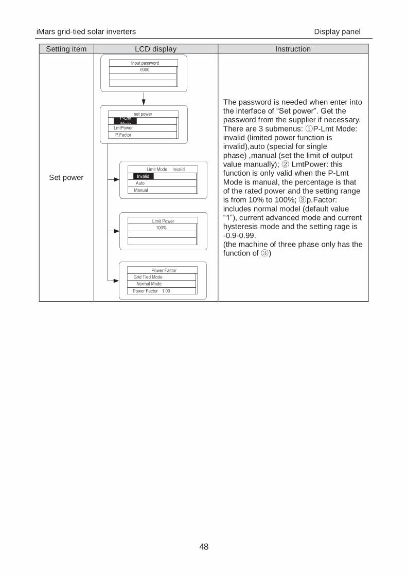
Setting item LCD display Instruction
Set power
set powerP-Lmt Mode
LmtPowerP.Factor
Limit Mode� InvalidInvalid
AutoManual
Limit Power100%
Power FactorGrid Tied Mode
Normal ModePower Factor� 1.00
Input password0000
The password is needed when enter into the interface of “Set power”. Get the password from the supplier if necessary. There are 3 submenus: P-Lmt Mode: invalid (limited power function is invalid),auto (special for single phase) ,manual (set the limit of output value manually); LmtPower: this function is only valid when the P-Lmt Mode is manual, the percentage is that of the rated power and the setting range is from 10% to 100%; p.Factor: includes normal model (default value “1”), current advanced mode and current hysteresis mode and the setting rage is -0.9-0.99. (the machine of three phase only has the function of )
iMars grid-tied solar inverters Display panel
49
Setting item LCD display Instruction
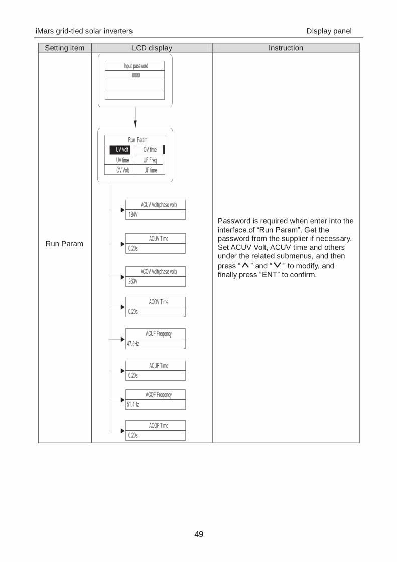
Run Param
Run ParamUV VoltUV timeOV Volt
OV timeUF FreqUF time
ACUV Volt(phase volt)184V
ACUV Time0.20s
ACOV Volt(phase volt)263V
ACOV Time0.20s
ACUF Freqency47.6Hz
ACUF Time0.20s
ACOF Freqency51.4Hz
ACOF Time0.20s
Input password0000
Password is required when enter into the interface of “Run Param”. Get the password from the supplier if necessary. Set ACUV Volt, ACUV time and others under the related submenus, and then press “ ” and “ ” to modify, and finally press “ENT” to confirm.

iMars grid-tied solar inverters Display panel
50
Setting item LCD display Instruction
Run Param*
Run ParamUV volt 1
UV time 1OV volt 1
OV time 1UF Freq 1UF time 1
ACUV Volt(phase volt)115V
ACUV Time00.04s
309V
00.02s
ACUF Frequency47.99Hz
00.12s
50.50hz
00.12s
·
Input Password0000
196V
252V
0.19s
01.90s
49.49Hz
595s
50.2Hz
115s
Run Restart Time
060s
Island protect:onOFFON
ACOV Volt(phase volt)
ACOV Time
ACUF Time
ACOF Frequency
ACOF Time
ACUV Volt(phase volt)
ACUV Time
ACOV Volt(phase volt)
ACOV Time
ACUF Frequency
ACUF Time
ACOF Frequency
ACOF Time
There are 2 protections under G83/G59(UK) and PEA(Thailand) standards, and there is only one protection under other grid tied standard. Set ACUV Volt, ACUV time and others under the related submenus, and then press “ ” and “ ” to modify, and finally press “ENT” to confirm. Generally, it is only necessary to set ACUV and ACUF value for ACUV and ACUF protection. And it is necessary to set ACOF1 and ACOF2 together for ACOF protection.
iMars grid-tied solar inverters Display panel
51
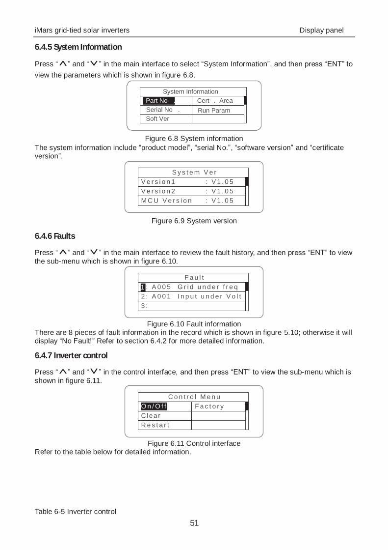
6.4.5 System Information
Press “ ” and “ ” in the main interface to select “System Information”, and then press “ENT” to view the parameters which is shown in figure 6.8.
System InformationPart No .Serial No .Soft Ver
Cert . AreaRun Param
Figure 6.8 System information
The system information include “product model”, “serial No.”, “software version” and “certificate version”.
S y s t e m V e rV e r s i o n 1 : V 1 . 0 5V e r s i o n 2 : V 1 . 0 5M C U V e r s i o n : V 1 . 0 5
Figure 6.9 System version
6.4.6 Faults
Press “ ” and “ ” in the main interface to review the fault history, and then press “ENT” to view the sub-menu which is shown in figure 6.10.
F a u l t1 : A 0 0 5 G r i d u n d e r f r e q2 : A 0 0 1 I n p u t u n d e r V o l t3 :
1
Figure 6.10 Fault information
There are 8 pieces of fault information in the record which is shown in figure 5.10; otherwise it will display “No Fault!” Refer to section 6.4.2 for more detailed information.
6.4.7 Inverter control
Press “ ” and “ ” in the control interface, and then press “ENT” to view the sub-menu which is shown in figure 6.11.
C o n t r o l M e n uO n / O f fC learR e s t a r t
F a c t o r y
Figure 6.11 Control interface
Refer to the table below for detailed information. Table 6-5 Inverter control
iMars grid-tied solar inverters Display panel
52
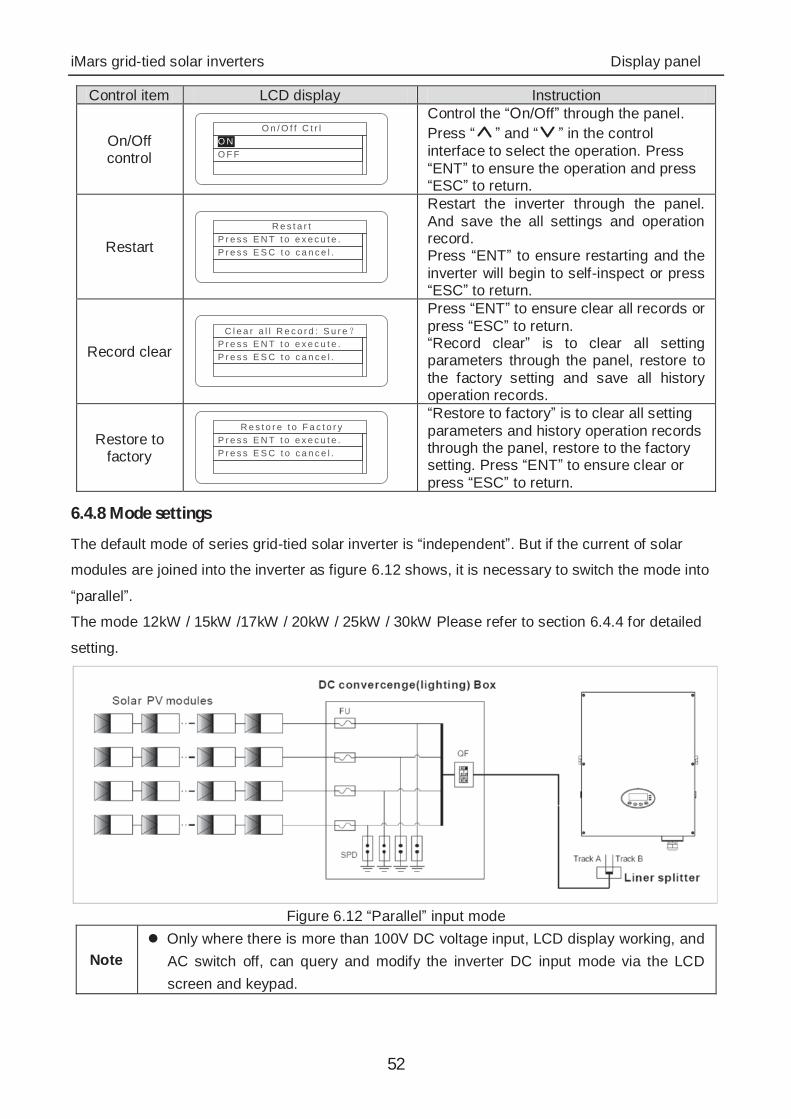
Control item LCD display Instruction
On/Off control
O n / O f f C t r lO NO F F
Control the “On/Off” through the panel. Press “ ” and “ ” in the control interface to select the operation. Press “ENT” to ensure the operation and press “ESC” to return.
Restart R e s t a r t
P r e s s E N T t o e x e c u t e .P r e s s E S C t o c a n c e l .
Restart the inverter through the panel. And save the all settings and operation record. Press “ENT” to ensure restarting and the inverter will begin to self-inspect or press “ESC” to return.
Record clear C l e a r a l l R e c o r d : S u r e
P r e s s E N T t o e x e c u t e .P r e s s E S C t o c a n c e l .
Press “ENT” to ensure clear all records or press “ESC” to return. “Record clear” is to clear all setting parameters through the panel, restore to the factory setting and save all history operation records.
Restore to factory
R e s t o r e t o F a c t o r yP r e s s E N T t o e x e c u t e .P r e s s E S C t o c a n c e l .
“Restore to factory” is to clear all setting parameters and history operation records through the panel, restore to the factory setting. Press “ENT” to ensure clear or press “ESC” to return.
6.4.8 Mode settings
The default mode of series grid-tied solar inverter is “independent”. But if the current of solar
modules are joined into the inverter as figure 6.12 shows, it is necessary to switch the mode into
“parallel”.
The mode 12kW / 15kW /17kW / 20kW / 25kW / 30kW Please refer to section 6.4.4 for detailed
setting.
Figure 6.12 “Parallel” input mode
Note Only where there is more than 100V DC voltage input, LCD display working, and
AC switch off, can query and modify the inverter DC input mode via the LCD screen and keypad.

iMars grid-tied solar inverters Display panel
53
6.5 Grid Certification Choice Power on the inverter by DC input for the first time or after Restore factory settings, it will appear on the LCD screen prompts as follows:
S O L A R I N V E R T E R
I n i t i a l i n g W a i t i n g> > > > > > >
Waiting a few seconds later, in the LCD screen will appear a list of countries as follows, requiring the user to choose what country of use. As shown below:
C o u n t r y : U n s e tGermanyU KA u s t r a l i a
G r e e c eD e n m a r kH o l l a n d
C o u n t r y : U n s e t
OtherD e n m a r kH o l l a n d
C h i n aT h a i l a n d
G r e e c e
Press the “ ” or “ ” button to navigate the country, press the ENT button to complete the setting. After determine the location, please follow the user manual required with the proper use of inverter. The user can change the location through the following ways: LCD Screen MENU Main Menu: Setup Setup Menu: Country Country:
V -pv1 : 000 .0VI -pv1 : 000 .0AV-pv2 : 000 .0V01 .A001MENUAla rm
p
hMENU
M a i n M e n uM o n i t P a r a mH i s t o r yS t a t i s t i c s
S e t u pS y s t e m I n f oF a u l t I n f o
S e t u p M e n u
A d d r e s sKeypad PWDC a s h / p r i c e
D a t e / T i m eL a n g u a g eC o u n t r y
C o u n t r y : C h i n aGermanyUK
A u s t r a l i a
G r e e c eD e n m a r kH o l l a n d
The user can query the grid certification which has been set through the following ways: LCD Screen MENU→Main Menu: System Info→System Information: Cert. Area→Certificate Area
V -pv1 : 000 .0VI -pv1 : 000 .0AV-pv2 : 000 .0V01 .A001MENUAla rm
p
hMENU
M a i n M e n uM o n i t P a r a mH i s t o r yS t a t i s t i c s
S e t u pS y s t e m I n f oF a u l t I n f o
S y s t e m I n f o r m a t i o n
P a r t N o .Ser ia l No .S o f t V e r
C e r t . A r e aR u n P a r a m
C e r t i f i c a t e A r e aA S 4 7 7 7
Comparison Table: Available Countries and their grid certification

iMars grid-tied solar inverters Display panel
54
No. Country Certification Remark
1 Germany VDE0126& AR-N4105
2 UK G83/G59
3 Australia AS4777
4 Greece VDE0126
5 Denmark TF321
6 Holland C10/C11
7 China CQC
8 Thailand PEA
9 Other VDE0126 Reference Table: Grid Certification and Grid Voltage and Frequency of Some Countries
No. Country Certification Three-phase voltage
Grid frequency
1 Germany
VDE0126& AR-N4105 380~400V 50Hz
2 France
3 Greece
4 Turkey
5 Romania
6 Slovakia
7 Portugal
8 Poland
9 Hungary
10 Switzerland
11 Austria
12 UK G83-2/G59-3 415V 50Hz
13 Australia AS4777.2&AS4777.3
AS/NZS3100 400~415V 50Hz 14 Singapore
15 New Zealand
16 Belgium
C10/C11 380~400V 50Hz 17 Luxembourg
18 Holland
19 Denmark TF3.2.1 380~400V 50Hz
20 Thailand PEA 380V 50Hz
21 China CGC/CF001 380V 50Hz
22 Italy ENEL 400V 50Hz
iMars grid-tied solar inverters Monitoring communication
55
7 Monitoring communication This chapter describes the communication connection of inverter and monitoring system
(Industrial master, private computers, smart phones and so on).
iMars grid-tied solar inverters Monitoring communication
56
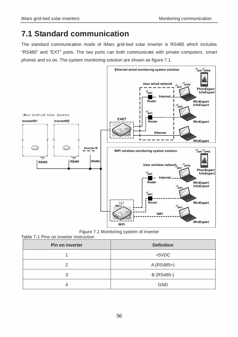
7.1 Standard communication The standard communication mode of iMars grid-tied solar inverter is RS485 which includes
“RS485” and “EXT” ports. The two ports can both communicate with private computers, smart
phones and so on. The system monitoring solution are shown as figure 7.1.
Figure 7.1 Monitoring system of inverter
Table 7-1 Pins on inverter instruction
Pin on inverter Definition
1 +5VDC
2 A (RS485+)
3 B (RS485-)
4 GND
iMars grid-tied solar inverters Monitoring communication
57
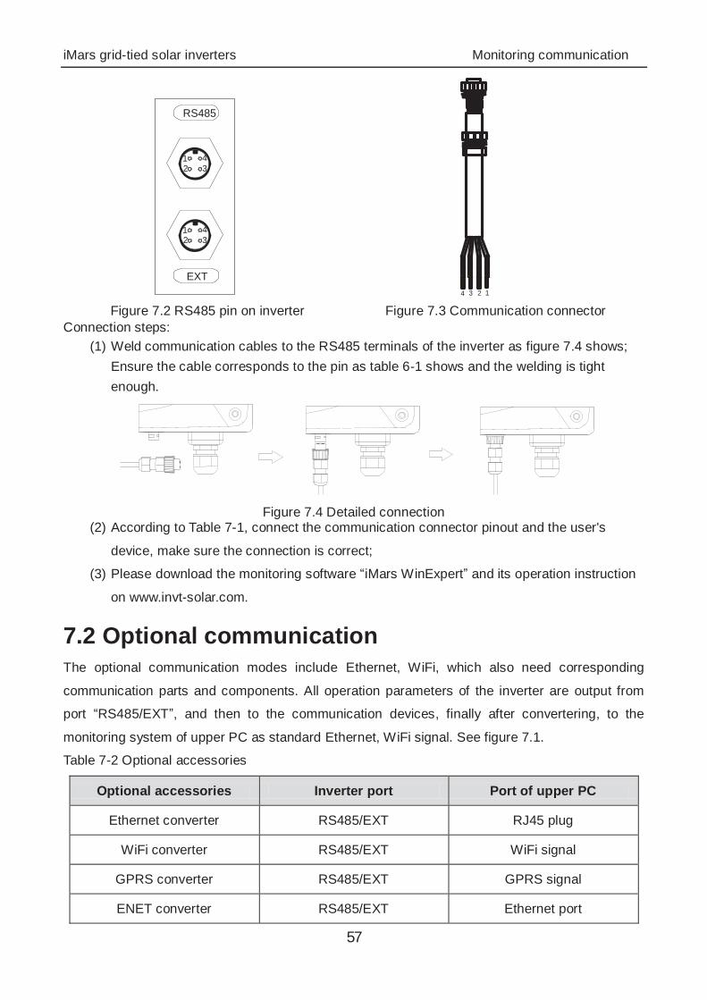
RS485
EXT
321 4
321 4
1234 Figure 7.2 RS485 pin on inverter Figure 7.3 Communication connector
Connection steps: (1) Weld communication cables to the RS485 terminals of the inverter as figure 7.4 shows;
Ensure the cable corresponds to the pin as table 6-1 shows and the welding is tight enough.
Figure 7.4 Detailed connection
(2) According to Table 7-1, connect the communication connector pinout and the user's
device, make sure the connection is correct;
(3) Please download the monitoring software “iMars WinExpert” and its operation instruction
on www.invt-solar.com.
7.2 Optional communication The optional communication modes include Ethernet, WiFi, which also need corresponding
communication parts and components. All operation parameters of the inverter are output from
port “RS485/EXT”, and then to the communication devices, finally after convertering, to the
monitoring system of upper PC as standard Ethernet, WiFi signal. See figure 7.1.
Table 7-2 Optional accessories
Optional accessories Inverter port Port of upper PC
Ethernet converter RS485/EXT RJ45 plug
WiFi converter RS485/EXT WiFi signal
GPRS converter RS485/EXT GPRS signal
ENET converter RS485/EXT Ethernet port
iMars grid-tied solar inverters Monitoring communication
58
Please download the connection instruction, operation manual and commissioning tools on
website www.invt-solar.com.
Note: the optional accessories are not standard-configured.
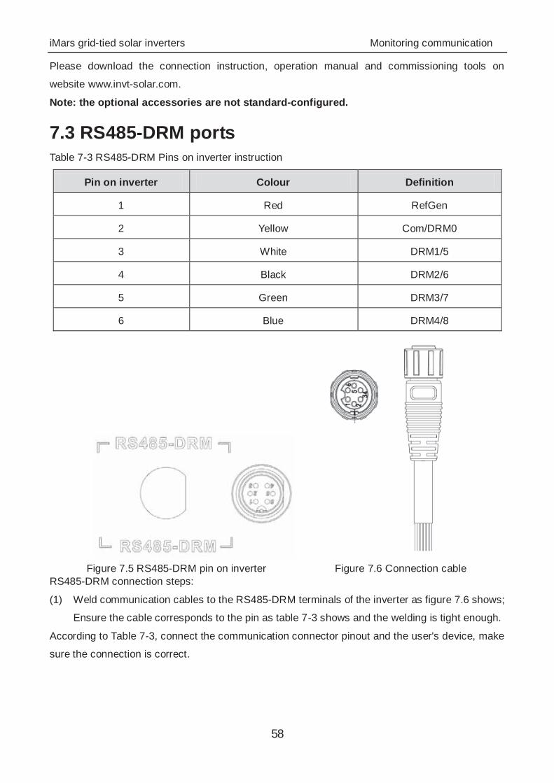
7.3 RS485-DRM ports Table 7-3 RS485-DRM Pins on inverter instruction
Pin on inverter Colour Definition
1 Red RefGen
2 Yellow Com/DRM0
3 White DRM1/5
4 Black DRM2/6
5 Green DRM3/7
6 Blue DRM4/8
Figure 7.5 RS485-DRM pin on inverter Figure 7.6 Connection cable
RS485-DRM connection steps:
(1) Weld communication cables to the RS485-DRM terminals of the inverter as figure 7.6 shows;
Ensure the cable corresponds to the pin as table 7-3 shows and the welding is tight enough.
According to Table 7-3, connect the communication connector pinout and the user's device, make
sure the connection is correct.
iMars grid-tied solar inverters Troubleshooting
59
8 Troubleshooting This chapter describes the fault alarm and fault code for quick troubleshooting.
iMars grid-tied solar inverters Troubleshooting
60
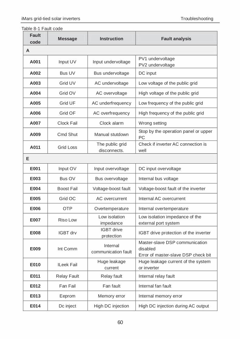
Table 8-1 Fault code Fault code
Message Instruction Fault analysis
A
A001 Input UV Input undervoltage PV1 undervoltage PV2 undervoltage
A002 Bus UV Bus undervoltage DC input
A003 Grid UV AC undervoltage Low voltage of the public grid
A004 Grid OV AC overvoltage High voltage of the public grid
A005 Grid UF AC underfrequency Low frequency of the public grid
A006 Grid OF AC overfrequency High frequency of the public grid
A007 Clock Fail Clock alarm Wrong setting
A009 Cmd Shut Manual stutdown Stop by the operation panel or upper PC
A011 Grid Loss The public grid disconnects.
Check if inverter AC connection is well
E
E001 Input OV Input overvoltage DC input overvoltage
E003 Bus OV Bus overvoltage Internal bus voltage
E004 Boost Fail Voltage-boost fault Voltage-boost fault of the inverter
E005 Grid OC AC overcurrent Internal AC overcurrent
E006 OTP Overtemperature Internal overtemperature
E007 Riso Low Low isolation impedance
Low isolation impedance of the external port system
E008 IGBT drv IGBT drive protection
IGBT drive protection of the inverter
E009 Int Comm Internal
communication fault
Master-slave DSP communication disabled Error of master-slave DSP check bit
E010 ILeek Fail Huge leakage
current Huge leakage current of the system or inverter
E011 Relay Fault Relay fault Internal relay fault
E012 Fan Fail Fan fault Internal fan fault
E013 Eeprom Memory error Internal memory error
E014 Dc inject High DC injection High DC injection during AC output

iMars grid-tied solar inverters Troubleshooting
61
Fault code
Message Instruction Fault analysis
E015 OutputShort Output short-circuit Output short-circuit
E018 Input OC Input overcurrent DC input overcurrent
E019 Incnst Data consistency
fault Inconsistent grid voltage, frequency, leakage current or AC/DC injection
E020 PowerReversed DC power reversed DC power reversed

iMars grid-tied solar inverters Troubleshooting
62
If any problem, please contact with the supplier and provide following information:
Model of the inverter: ;
Serial No. of the inverter: ;
System version: version 1: ;
version 2: ;
MCU software version: ;
Fault code: ;
Fault description .
iMars grid-tied solar inverters Contact us
63
9 Contact us Shenzhen·China
INVT Solar Technology (Shenzhen) Co., Ltd.
Address: Room 504, No. 7 Building, Gaofa Scientific Industrial Park, Longjing, Nanshan District,
Shenzhen, China
Service hotline: +86 400 700 9997
E-mail: [email protected]
INVT group website: www.invt.com
INVT solar website: www.invt-solar.com
iMars grid-tied solar inverters Technical parameters
64
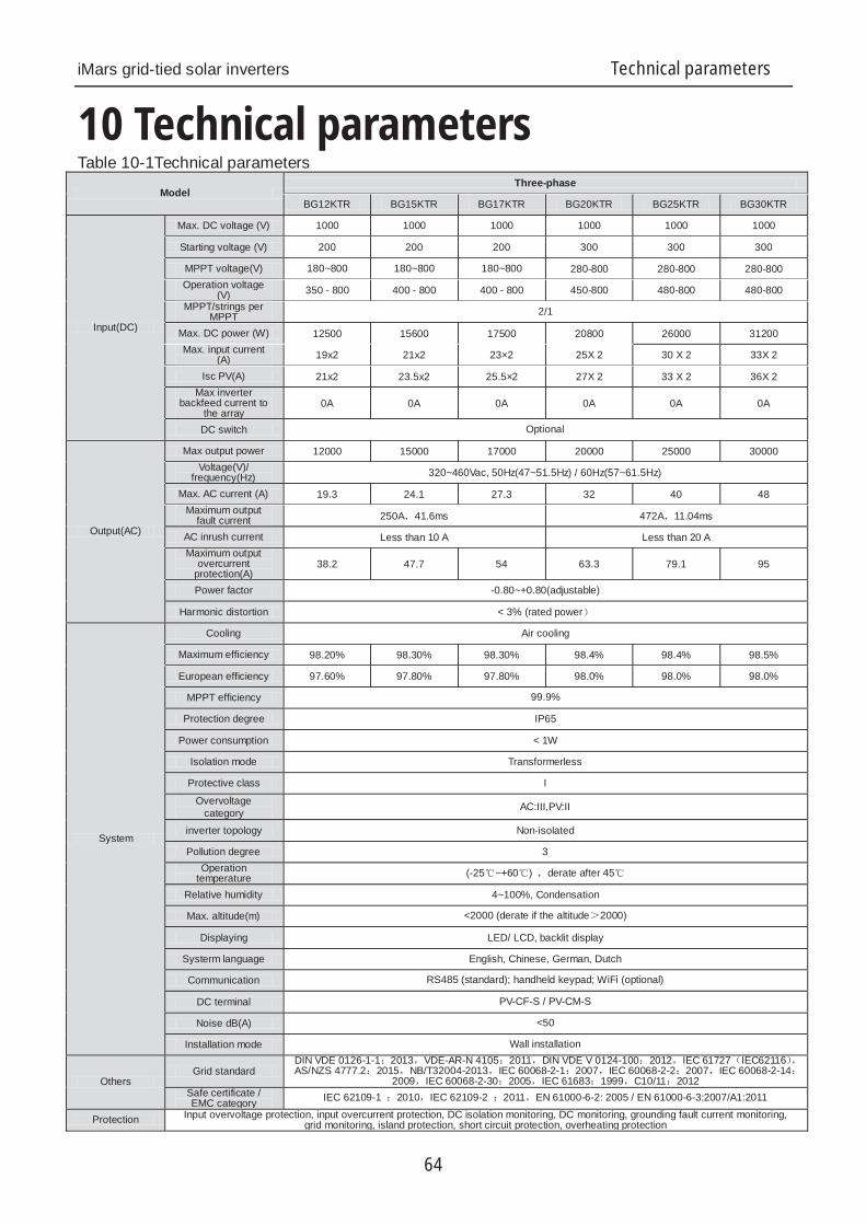
10 Technical parameters Table 10-1Technical parameters
ModelThree-phase
BG12KTR BG15KTR BG17KTR BG20KTR BG25KTR BG30KTR
Input(DC)
Max. DC voltage (V) 1000 1000 1000 1000 1000 1000
Starting voltage (V) 200 200 200 300 300 300
MPPT voltage(V) 180~800 180~800 180~800 280-800 280-800 280-800Operation voltage
(V) 350 - 800 400 - 800 400 - 800 450-800 480-800 480-800MPPT/strings per
MPPT 2/1
Max. DC power (W) 12500 15600 17500 20800 26000 31200Max. input current
(A) 19x2 21x2 23×2 25X 2 30 X 2 33X 2
Isc PV(A) 21x2 23.5x2 25.5×2 27X 2 33 X 2 36X 2Max inverter
backfeed current to the array
0A 0A 0A 0A 0A 0A
DC switch Optional
Output(AC)
Max output power 12000 15000 17000 20000 25000 30000Voltage(V)/
frequency(Hz) 320~460Vac, 50Hz(47~51.5Hz) / 60Hz(57~61.5Hz)
Max. AC current (A) 19.3 24.1 27.3 32 40 48Maximum output
fault current 250A 41.6ms 472A 11.04ms
AC inrush current Less than 10 A Less than 20 AMaximum output
overcurrent protection(A)
38.2 47.7 54 63.3 79.1 95
Power factor -0.80~+0.80(adjustable)
Harmonic distortion < 3% (rated power
System
Cooling Air cooling
Maximum efficiency 98.20% 98.30% 98.30% 98.4% 98.4% 98.5%
European efficiency 97.60% 97.80% 97.80% 98.0% 98.0% 98.0%
MPPT efficiency 99.9%
Protection degree IP65
Power consumption < 1W
Isolation mode Transformerless
Protective class I
Overvoltage category AC:III,PV:II
inverter topology Non-isolated
Pollution degree 3Operation
temperature (-25 ~+60 ) derate after 45
Relative humidity 4~100%, Condensation
Max. altitude(m) <2000 (derate if the altitude 2000)
Displaying LED/ LCD, backlit display
Systerm language English, Chinese, German, Dutch
Communication RS485 (standard); handheld keypad; WiFi (optional)
DC terminal PV-CF-S / PV-CM-S
Noise dB(A) <50
Installation mode Wall installation
OthersGrid standard
DIN VDE 0126-1-1 2013 VDE-AR-N 4105 2011 DIN VDE V 0124-100 2012 IEC 61727 IEC62116AS/NZS 4777.2 2015 NB/T32004-2013 IEC 60068-2-1 2007 IEC 60068-2-2 2007 IEC 60068-2-14
2009 IEC 60068-2-30 2005 IEC 61683 1999 C10/11 2012Safe certificate / EMC category IEC 62109-1 2010 IEC 62109-2 2011 EN 61000-6-2: 2005 / EN 61000-6-3:2007/A1:2011
Protection Input overvoltage protection, input overcurrent protection, DC isolation monitoring, DC monitoring, grounding fault current monitoring, grid monitoring, island protection, short circuit protection, overheating protection


201807(V1.1)