invisible ir guard camera - securitysystems.com · please avoid the laser beam point to your eyes....
TRANSCRIPT

Model: iExGuard Series
Invisible IR Guard Camera
INSTRUCTION MANUAL
V1.1 2013.Mar

2
TABLE OF CONTENTS
Camera Kit Contents………………………………...….3
Camera Overview…………….…………………………..4
General Information……………………………………..8
Definitions………….…………………………………………9
Quick Start Guide………………………………………….12
Battery and Memory Installation……………….…13
Camera Setup and Program…………………….…..15
Using the Camera in PIR Detection Mode….…27
Using the Camera in Time Lapse Mode…….….29
Viewing and Deleting Files…………………..……...30
Technical Specifications……………………….….…..34
FCC Compliance…………………………………….….….37

3
Camera Kit Contents
1. Invisible IR Guard Camera.
2. Instruction Manual.
3. Strap.
4. USB Cable.
5. AV Cable.
6. Wall Mounting Device.
7. Mounting screws.

Camera Overview
Front View
4

Back View
5

Top View (After Open Top Cover)
Bottom View
6

Open Bottom Cover Image with major parts indication
• Follow below figure to turn the bottom cover to open .
7

8
General Information
Storing conditions • Operating Environment: ‐4 to 122 deg F (‐20 to 50 deg C).
20‐85% relative humidity, non‐condensing.
Special care instructions!! • The camera is designed to be weather resistant. Never
attempt to immerse the unit in water or any other liquid. This will damage the unit and void the warranty.
• Use a soft lens cloth for cleaning lens. Avoid touching lens with fingers. And remove dirt or stains with a soft cloth dampened with water or neutral detergent. Keep your camera in a dry and cool dust‐free environment or container when it is NOT used.
• Take the batteries out, when camera is NOT to be used over an extended period of time.
• Avoid dropping your camera on to a hard surface.
• Do not disassemble your camera.
• Do not mix new and old batteries.
• Do not open the camera for unauthorized service. This could cause serious damage to the unit and WILL void the warranty.
NOTE : This camera is a precision electronic device. Do not attempt to service this camera yourself, as opening or removing covers may expose you to dangerous voltage points or other risks.

Definitions
Definitions of Front View parts • Batteries Cover : Turn to open the cover to install the
batteries.
• Infrared LED : It is invisible light for night time capture.
• Camera Lens : It is to capture the image/video.
• Test Laser Beam : It is to identify the capture area and countdown indication.
Please avoid the laser beam point to your eyes.
• Microphone : It is to pick up the sounds while video in recording.
• Passive Infrared Sensor : It is to detect the moving object.
• Bottom Cover : Turn to open the cover to set the camera.
Definitions of Back, Top and Bottom view parts • Tripod Nut : It is to attach the wall mount device.
• Strap Holes : It is to attach the camera to pillar or tree by provided strap.
• Batteries Compartment : It is to install the C batteries.
• DC 6 Volts Port Cover : Open it to connect a DC 6V external power. Tightly close to prevent the water leakage.
NOTE : Make sure the installed batteries or the external power is in correct polarity.
9

Definitions of Bottom Open View parts • LCD display : It is to display the setting and camera status.
• USB port : It is to connect the camera to PC by provide USB cable for captured image/video download.
• AV out : It is to connect the camera to TV by provide AV cable to play the captured image/video.
• Menu Button : Pressing into the camera mode to change the setting.
• Up and Down Button : Pressing to change the mode and adjust the setting value.
• Switch : Switching to turn on/off the power or go into test/Preset Mode.
• SD Card Slot : It is to install the SD memory card.
• Confirm Button : Pressing to confirm the settings.
• DC 6V port : It is to connect the DC 6V external power
Definitions of LCD Display
10

• CAM : It indicates the camera in still image mode.
• VIDEO : It indicates the camera in vide mode.
• : It indicates the burst mode or video length.
• : It indicates the battery status.
> < > <
11
> < Full (Icon on) Half (Icon blinking) Low (Icon off)
When batteries are low, the LCD display shows bAtLo. Please replace with new batteries.
• : It indicates the still image/video resolutions.
Image resolution is 8Mp.
Image resolution is 5Mp or video resolution is HD 720P.
Image resolution is 3Mp or video resolution is VGA
• D : It indicates the camera in date setting. • T : It indicates the camera in time setting.
• T-O : It indicates the camera in time out setting.
• PIR : It indicates the camera in PIR detection Mode.
• TLS : It indicates the camera in Time Lapse Mode.
• : It indicates the date/time/time out value during setting or captured image/video quality. The date and time will stamp to the still image and video

12
Quick Start Guide This guide is designed to get you up and running in a matter of moments. To get the most out of this Invisible IR Guard Camera tools, please read the manual thoroughly before operating. If you would like to modify any of the factory Default Settings, except for the Time & Date, please see manual for instructions.
Factory Default Settings: Time Out: 30 Sec Burst Mode: 3 Still Image Resolution: 3M Operation Mode: PIR Video Mode: 10 Seconds (VGA Resolution) Time lapse setting: 19:00‐7:00 (Next day)
Initial Camera Set‐up: 1. Install 4 “C” cell batteries in correct polarity (+/‐) as indicated in
battery compartment. 2. Insert SD card into the camera. 3. Turn switch to CAM to adjust the Time and Date. 4. The internal LCD screen displays T blinking. 5. Press the [OK] button to start the Time settings. 6. Press the [UP] or [DN] button to adjust the Minute setting and
press [OK] to confirm and move to the Hour setting. 7. Repeat to set the Hour and then press [OK] to confirm and
move to Date. 8. Adjust the Month, Day, and Year by using [UP] or [DN] button.
Each time you finish an adjustment you MUST press the [OK] button to confirm and move to the next field for adjustment.
9. Once done, the word ‐ dEL ‐ will be blinking, this stands for Delete menu and will allow you to format your SD Card. (This will delete ALL images). Press the [M] button to exit.

13
Battery and Memory Installation WARNING : Do not use different Voltage lead acid battery other than the one specified in this section. Doing so will damage the camera and will void the warranty.
WARNING : ALWAYS have the camera in the OFF position when installing or removing batteries and memory card. Removing batteries or memory card while the camera is ON may damage the camera.
Your Invisible IR Guard Camera is designed to operate using two different types of battery power options.
Batteries “C” cell The internal battery compartment accepts 4 “C” cell batteries. Be sure to use high quality brand name alkaline batteries. Install batteries with correct polarity (+/‐) as noted inside the battery compartment.
DC 6V external power The camera is equipped with an external power jack designed to accept a barrel plug cable of DC 6V adaptor (Sold separately).
• Make sure camera is in the OFF position.
• Insert the external AC to DC power adaptor barrel plug into the DC 6V jack on the bottom of camera housing.
• Turn the switch to a CAM or PSET.

14
Memory Options The camera is also equipped with an expandable media card slot capable of accepting up to 32GB SD card with Class 6 or below speed rating (sold separately). The LCD display will show the number of images stored on the SD card. If no SD card is inserted the front counter display will show “NOSd”.
Inserting SD memory card NOTE: Make sure camera is in the OFF position whenever adding or removing memory.
• Insert SD memory card in to the SD card slot completely and in the correct direction as shown by the sticker located at the side of the housing.
• To remove the SD memory card, depress the SD card and pull out the card gently.
• SD cards must be clean (no images from other sources). If you are using the SD card from other cameras, please make sure to format the SD card in your computer prior to use in your camera. New cards are good to use straight from the package.
FORMAT – Definition : When you format a SD memory card, the operating system erases all information and files on the card. Then it creates an internal address tables that it later uses to locate information and files. Formatting also removes all Hidden System files as well. Basically it cleans your SD memory card just like if it was brand new.
DO NOT USE File System type: “NTFS” or “exFAT”, these formats are not supported.

Camera Setup and Program When the camera switch is first turned in the CAM location, the internal LCD display shows the camera status. The following information is present on this screen.
Passive Infrared Mode Time‐Lapse / PIR Mode
If no buttons are pressed after 30 seconds the LCD display will go to sleep mode and LCD display switch to show the capture quality and enter 1‐minute count down for user leave the capture area, then camera enter PIR detection mode or Time lapse mode. To wake up the camera by press UP or DOWN button once, the LCD display will resume the status of camera.
Setting the Preset Program Selection Mode: This camera is equipped with 2 Program selection toggle switch settings. Make sure camera switch is in the OFF position BEFORE changing any toggle switches.
NOTE: If you choose one of the Preset settings, your camera will only function in PIR mode not Time Lapse mode
• CAM ‐ This allows the user to define what setting the camera will use.
15

• PSET ‐ This bypasses all user defined settings and uses the following settings: (PIR mode / Resolution: 3MP / Burst: 3P / Time out: 30 seconds).
16
Program Invisible IR Guard Camera using CAM mode Setting the CAM Operation Mode: Your Invisible IR Guard Camera can be programmed to operation either in PIR Detection mode or Time Lapse / PIR mode.
• Slide the switch to the CAM position.
• LCD display will show the camera status screen.
• Press the [M] button once within 30 seconds to enter the programming mode, the word PIR or TLS will be blinking.
• Press the [UP] or [DN] button to select PIR mode.
• Press [OK] to save your selection.
• Press [M] button to exit.
Setting the Image Resolution in PIR mode: Your Invisible IR Guard Camera can be programmed to 3 different image resolutions: 3 Stars is 8Mp, 2 Stars is 5Mp and 1

17
Star is 3Mp. • Slide the switch to the CAM position, LCD display will
show the camera status screen.
• Press the [M] button once within 30 seconds to enter the programming mode.
• The word PIR will be blinking, press [OK] to confirm the camera’s operation is PIR detection.
• Press [UP] or [DN] button until the word CAM is blinking.
• Press the [OK] button ONCE to confirm the camera into CAM mode, the STARTS will be blinking.
• Press the [UP] or [DN] button to select the desired resolution.
• Press [OK] to save your selection, then current number of burst shoot will blinking. Press [OK] to enter the burst shoot setting or press [M] button to exit.
Setting the Image burst shoot in PIR mode: Your Invisible IR Guard Camera can be programmed to shoot 1‐9 pictures per triggering. • Slide the switch to the CAM position, LCD display will
show the camera status screen.
• Press the [M] button once within 30 seconds to enter the programming mode.
• The word PIR will be blinking, press [OK] to confirm the camera’s operation is PIR detection.
• Press [UP] or [DN] button until the word CAM is blinking.

18
• Press [OK] button ONCE to confirm camera into CAM mode.
• Press [UP] button ONCE to enter burst shoot setting, the current number of burst shoot will blink.
• Press [OK] then press the [UP] or [DN] button to select the desired burst mode setting or number of pictures per triggering.
• Press [OK] to save your selection, then the time out T‐O will blinking. Press [OK] button to enter time out setting or press [M] button to exit.
Setting the Video Resolution in PIR mode: Your Invisible IR Guard Camera can be programmed to 2 different video resolutions: 2 Stars is HD 720, 1 Stars is VGA 640 x 480 pixels. • Slide the switch to the CAM position, LCD display will
show the camera status screen.
• Press the [M] button once within 30 seconds to enter the programming mode.
• The word PIR will be blinking, press [OK] to confirm the camera’s operation is PIR detection.
• Press [UP] or [DN] button until the word VIDEO is blinking.
• Press the [OK] button ONCE to confirm the camera in VIDEO mode, the STRAS will be blinking.
• Press the [UP] or [DN] button to select the desired resolution.
• Press [OK] to save your selection, then current number of

19
video length will blinking. Press [OK] button to enter video length setting or press [M] to exit.
Setting the Video length in PIR mode: Your Invisible IR Guard Camera can be programmed to record 5‐600 seconds of video per triggering. The Video mode is only workable under PIR mode. • Slide the switch to the CAM position, LCD display will
show the camera status screen.
• Press the [M] button once within 30 seconds to enter the programming mode.
• The word PIR will be blinking, press [OK] to confirm the camera’s operation is PIR detection.
• Press [UP] or [DN] button until the word VIDEO is blinking.
• Press the [OK] button ONCE to confirm the camera in VIDEO mode.
• Press [UP] button ONCE and the video length in seconds will be blinking.
• Press [UP] or [DN] button to select the desired video length from 5 to 300 seconds in 5‐second increments.
• Press [OK] to save your selection then the time out T‐O will blinking. Press [OK] button to enter time out setting or press [M] button to exit.
Setting the Time Out in PIR mode: Your Invisible IR Guard Camera can be programmed to set the

20
amount of time in seconds or minutes the camera will sleep between PIR triggers. • Slide the switch to the CAM position, LCD display will
show the camera status screen.
• Press the [M] button once within 30 seconds to enter the programming mode.
• The word PIR will be blinking, press [OK] to confirm the camera’s operation is PIR detection.
• Press [UP] or [DN] button until the word T‐O (Time Out) is blinking.
• Press [OK] button and the MINUTES digits will be blinking.
• Press [UP] or [DN] button to increase or decrease the time value in minutes from 00 to 10 minutes in 1‐minute increments.
• Press [OK] to save the seconds setting and the SECONDS digits will be blinking.
• Press [UP] or [DN] button to increase or decrease the time value in seconds from 05 to 55 seconds in 5 second increments.
• Press [OK] to save the seconds setting.
• You’ll then see the word T (Time) blinking. Press [OK] button to enter time setting or press [M] button to exit.
Setting the Time and Date in PIR operation mode: Your Invisible IR Guard Camera uses the 24hr military time format. • Slide the switch to the CAM position, LCD display will

21
show the camera status screen.
• Press the [M] button once within 30 seconds to enter the programming mode.
• The word PIR will be blinking, press [OK] to confirm the camera’s operation is PIR detection.
• Press [UP] or [DN] button until the word T is blinking.
• Press [OK] to enter Minute setting first.
• The MINUTE digits will be blinking.
• Press [UP] or [DN] to increase or decrease the minute value (00 – 59).
• Press [OK] to save your selection and enter Hour setting.
• The HOUR digits will be blinking.
• Press [UP] or [DN] to increase or decrease the hour value (00 – 23).
• Press [OK] to save your selection and enter Month setting.
• The MONTH digits will be blinking.
• Press [UP] or [DN] to increase or decrease the Month value (1 ‐ 12).
• Press [OK] to save your selection and enter Day setting.
• The DAY digits will be blinking.
• Press [UP] or [DN] to increase or decrease the Day value (01 – 31).
• Press [OK] to confirm the Date setting and enter Year setting.

22
• The YEAR digits will be blinking.
• Press [UP] or [DN] to increase or decrease the Year value (01 – 99).
• Once this is all done, press [OK]. You’ll then see the word ‐ dEL ‐ blinking.
• Press [M] button to exit the program setting and back to the status screen.
Setting the Time Lapse Mode: The Time Lapse default setting value is from 17:00 to 07:00 the next day. When the camera is set to use the Time‐Lapse mode (TLS), the program settings will follow the Time Lapse settings. Outside of the Time Lapse time frame; the camera will follow the user defined PIR settings. The user can set the program for a pre‐determined time period [such as 19:00 to 07:00]. The user then sets the frequency of still images only (video function not available in Time Lapse mode). The camera will remain in Time Lapse mode until the user has changed the program setting. • Slide the switch to the CAM position, LCD display will
show the camera status screen.
• Press the [M] button once within 30 seconds to enter the programming mode, the word PIR or TLS will be blinking.
• Press [UP] button until you see the word TLS blinking.

• Press [OK] to confirm and go into TLS Mode "Start Time" setting.
• The display will show T + S‐88:88 (S = Start, 88:88 = time in HH:MM).
• Press [OK] to set the “Start Time” setting. At this point you can adjust the time from 00:00 to 23:59.
• The MINUTE digits will be blinking.
• Press [UP] or [DN] to increase or decrease the minute value (00 – 59).
• Press [OK] to save your selection and enter Hour setting.
• The HOUR digits will be blinking.
• Press [UP] or [DN] to increase or decrease the hour value (00 – 23).
• Press [OK] to save the “Start Time” setting and move to the “End Time” setting.
• After completing the start time setting, camera will go into TLS Mode "End Time" setting.
• The display will show T + E‐88:88
• (E = End, 88:88 = time in HH:MM)
• At this point you can adjust the time from 00:00 to 23:59 by pressing the [UP/DN/OK] buttons same as Start Time settings.
23

24
• Press [OK] to save the “End Time” settings and move directly to the TIME OUT setting.
• Please complete the TIME OUT, Still Image Resolution, Burst Mode, Zoom settings like the settings on the PIR operation mode.
• Then press [M] button to exit.
EXAMPLE: #1: If a user selected the Time Lapse mode, and sets the Start Time to 07:00 and End Time at 20:30, then selects the Timeout to be 3 mins with a Burst mode of 3 pictures, this means that the camera will keep taking 3 pictures for every 3 minutes within the time frame of 7:00AM to 8:30PM. When not within the Time Lapse time frame, the camera will follow the normal PIR detection settings.
#2: If a user selected the Time Lapse mode setting as Start Time 00:00 and End Time 00:00, then selected the Timeout to be 5 mins with a Burst mode of 3 pictures, this means the camera will keep taking 3 pictures for every 5 minutes, 24 hours a day non‐stop.
Time Lapse Setup Recommendations: We recommend that if your using the Time Lapse feature and what to extend your battery life and get the most pictures possible, use the following settings: Batteries: Energizer Lithium Batteries Resolution: Base (1 Star–3Mp) Time Out: 15 seconds
25
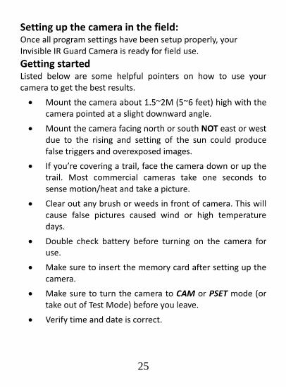
Setting up the camera in the field: Once all program settings have been setup properly, your Invisible IR Guard Camera is ready for field use. Getting started Listed below are some helpful pointers on how to use your camera to get the best results.
• Mount the camera about 1.5~2M (5~6 feet) high with the camera pointed at a slight downward angle.
• Mount the camera facing north or south NOT east or west due to the rising and setting of the sun could produce false triggers and overexposed images.
• If you’re covering a trail, face the camera down or up the trail. Most commercial cameras take one seconds to sense motion/heat and take a picture.
• Clear out any brush or weeds in front of camera. This will cause false pictures caused wind or high temperature days.
• Double check battery before turning on the camera for use.
• Make sure to insert the memory card after setting up the camera.
• Make sure to turn the camera to CAM or PSET mode (or take out of Test Mode) before you leave.
• Verify time and date is correct.

(Example: Mounting)
26
Pillar or tree mounting Wall mounting
(Example: Trail Setup)
Effective Range Effective Angle

27
Using The Camera in PIR Detection Mode • Mount the camera to the tree or wall or other sturdy
object using either a supplied wall mounting device or supplied mounting strap.
• Open the bottom housing and slide the switch to either one of the CAM or PSET modes. At this point, you have 30 seconds to make any mode selection changes before camera is ready to use.
• If you chose CAM mode then make sure your camera is in the PIR mode and not Time Lapse (TLS). If you are not sure, please follow the “Camera setup and program” above to set the camera into the proper mode.
To Capture Images, make sure display reads CAM: Once in CAM mode, if the display does not read CAM then,
• Press the [M] button once.
• If the LCD display does not show word CAM in blinking.
• Press the [UP] button ONCE to toggle to Camera mode.
• Press the [OK] button and then [M] Button to exit.
To Capture Videos, make sure display reads VIDEO: Once in CAM mode, if the display does not read VIDEO then,
• Press the [M] button once.
• If the LCD display does not show word VIDEO in blinking.
• Press the [UP] button ONCE to toggle to Video mode.

28
• Press the [OK] button and then [M] Button to exit.
• 30 seconds after you’ve made your adjustments, the laser beam will begin blinking and enter count down mode. This is your indication to leave the coverage area within one minute.
• After one minute, the camera will enter either Burst mode or Video mode based on your program setting. The camera will then time out between 05‐59 seconds or 1‐59 minutes, depending on your program setting.
NOTE: The time between motion detection and the camera taking the pictures may vary due to lighting conditions, program settings, and battery power level. The IR Emitter will only activate in low light conditions.

29
Using The Camera In Time Lapse Mode • Mount the camera to the tree or wall or other sturdy
object using either a supplied wall mounting device or supplied mounting strap.
• Open the bottom housing and slide the switch to CAM mode. At this point, you have 30 seconds to make any mode selection changes before camera is ready to use.
• Make sure your camera is in Time Lapse (TLS) mode and not PIR mode. If your not sure, please follow the “Camera setup and program” above to set the camera into TLS mode.
• 30 seconds after you’ve made your adjustments, the laser beam will begin blinking and enter countdown mode. This is your indication to leave the coverage area within one minute, then the camera will enter Time Lapse Mode.

Viewing and Deleting Files The Invisible IR Guard Camera offers the user different options for viewing their images. You can view images or videos through either on your computer, or your home TV that’s equipped with an RCA Input jack. The LCD display on bottom of the housing will show the number of images stored on the SD memory card.
NOTE: The instructions below are based on starting with a camera that’s power is turned off.
Viewing files by computer Your Invisible IR Guard Camera is a plug and play USB storage device for users of Windows 2000 / ME / XP / Vista / Windows 7 operating systems. This camera is compatible with MAC 10.6 and above.
Viewing files on your computer via USB connection. • Make sure the camera’s power switch is in the OFF
position.
• Plug the larger end of the USB cable into an available USB port on your computer.
30

31
• Plug the smaller end of USB cable into the camera’s side panel.
• The camera will automatically power ON and display the word USb on the LCD display.
• At the same time, your computer will recognize the camera as a Removable Storage device. You will find it under MY COMPUTER.
• At this point you have several options: To view your images or play your videos: Click on the Removable Storage device and then drill down to the file you want to see and double click on the file name.
To save your images and videos: Highlight the file or files you want to save and drag them to your hard drive.
To delete your images and videos: Highlight the files or files you want to delete and press the [DELETE] button.
To erase all files and reformat you SD memory card: Right click on the Removable Storage device under My Computer and select FORMAT then click START. You will receive a Warning message press [OK]. Then CLOSE to exit.
NOTE: Make sure before you FORMAT you are certain it is the Removable Storage device for the camera.
• Once you’re done, simply unplug the cable from both your computer and the camera. The camera will turn OFF automatically.

For Viewing on Your home TV: • Attach the provided TV out cable to the TV port on the
bottom of the camera.
• Insert the other end into the RCA VIDEO IN jacks on the TV.
• Turn on both the camera and the TV.
• Make sure to switch to AUX / VIDEO IN mode on your TV. (See your TV owner’s manual for directions).
• The camera’s TV OUT is set to NTSC by default. (NTSC – Standard North American TV format) If the TV monitor doesn’t flicker, then you do not need to change your camera’s TV OUT setting. Proceed to the next section called Thumbnail Images.
If the TV monitor does flicker, then you will need to proceed to the next step ‘TV Out System Settings” to change your camera’s TV OUT from NTSC to PAL (Standard European TV format).
• You will see a series of thumbnail images on your TV.
• Press the [UP] or [DN] button to navigate though your thumbnail images.
• On the upper left hand corner of your TV monitor, it will either display the image OR the image with a video icon which indicates it’s a video clip.
• To view in full screen, press the [OK] button.
• Press the [OK] button again, it will return to the thumbnail view from the full screen image.
32

33
NOTE: All videos are recorded with audio but only have sound when viewing playback on a PC.
TV Out System Settings: • Press the [M] button once.
• The word “ tu ” on the camera’s internal screen will be blinking.
• Press the [OK] once and now you’ll see “ tu – n “ blinking.
• Press the [DN] button to set the camera’s TV OUT to PAL.
• The word “ tu – P ” will now be blinking.
• Press the [OK] to confirm this setting.
• The word “ tu ‐ P “ will be blinking and then stops.
• Once the blinking stops, power off the camera. Wait for 5 seconds and then power up your camera again.
Deleting files in the field • Slide the switch the CAM position.
• LCD screen will display the camera status screen.
• Press the [M] button within 30 seconds to enter the programming mode.
• Press the [DN] button until you see the word ‐ dEL ‐ in blinking on LCD display.
• Press [OK] button to enter the DELETE & FORMAT menu.
• Press [UP] or [DN] button to select the desired function. NO‐dL (No Delete) ‐ No images get deleted.
d‐ONE (Delete One) ‐ Only the last file will get deleted.

34
d‐ALL (Delete ALL) ‐ Deletes ALL images on the SD card.
Ft (Format) ‐ Deletes all files and reformats the SD card.
• Press [OK] to confirm your selection.
• Press [M] button to exit the program setting and back to the status screen.
Technical Specifications
System Requirements and Compatibility: • Windows Me/2000/XP/Vista/Windows 7 and MAC 10.6 or
above
• Pentium 4, 2GHz or above
• 1GB RAM (2GB recommended)
• 32 bits color, Resolution 800x600 or above w/ 256MB
• 2GB free hard disc space
• An available USB 1.1 port (USB 2.0 recommended)
• Direct X 9.0 or above – Should come with your operating system already.
• Windows compatible sound card and speaker.
NOTE: If you have any questions regarding your PC specifications please contact your PC manufacturer.

35
Camera Features and Specification: • High precision multi‐layer glass lens with coating.
• Focusing: 1.5M (5 ft) to infinity.
• Effective viewing angle: 50 degrees
• Infrared LED effective Range for picture up to 22M (75 ft).
• Infrared LED effective Range for Video clip up to 22M (75 ft).
• PIR detection angle: 48 degrees
• Image resolution Options: 8.0M, 3.0M, 3M.
• Video resolution Options: HD 720P, VGA 640 x 480 pixels with Audio recording.
• Image interpolated from 5M Sensor
• Capturing Options: 1 ‐ 9 image burst mode or 300 seconds video recording with audio.
• Time Lapse Mode: Sets the frequency of pictures during a time period.
• Hybrid mode: PIR capture and Time Lapse mode auto changing.
• Time Out Feature: 5 secs – 600 secs
• Real time clock for date and time stamping.
• Image format: Standard JPEG/Motion JPEG.
• Auto white balance and auto expose.
• Auto IR emitter light control.
• Built in B&W LCD display.

36
• External memory support: SD memory card up to 32GB.
• Laser beam TEST indication and countdown indication.
• Interface type: USB 2.0
• Built in TV out port.
• Power: C size alkaline Batteries x 4
• External power: DC 6 Volts battery pack or power adaptor (Sold separately)
FCC Compliance This equipment has been tested and found to comply with the limits for Class B digital device, pursuant to part 15 of the FCC Rules. These limits are designed to provide reasonable protection against harmful interference in a residential installation. This equipment generates uses and can radiate radio frequency energy and, if not installed and used in accordance with the instructions, may cause harmful interference to radio or television receptions, which can be determined by turning the equipment off and on, the user is encouraged to try to correct the interference by one or more of the following measure:
• Reorient or relocate the receiving antenna.
• Increase the separation between the equipment and the receiver.
• Connect the equipment into an outlet on a circuit different from that to which the receiver is connected.
• Consult the dealer or an experienced radio/TV technician for help.

37
• Shield USB cable with ferrite must be used with this unit to ensure compliance with the Class B FCC limits.
This device complies with part 15 of the FCC Rules. Operation is subject to the following two conditions: (1) This device may not cause harmful interference, and (2) this device must accept any interference received, including interference that may cause undesired operation.
Warning: Changes or modifications to this unit not expressly approved by the party responsible for compliance could void the
user's authority to operate the equipment Version Update:
R1.1 Will be MP version. 1/Mar, 2013 Another Version Update maybe have SD card overwriting function