investigations on the dynamic station keeping of an ... · pdf filesanthakumar, asokan:...
TRANSCRIPT

Int j simul model 10 (2011) 3, 145-157
ISSN 1726-4529 Professional paper
DOI:10.2507/IJSIMM10(3)4.185 145
INVESTIGATIONS ON THE DYNAMIC STATION KEEPING
OF AN UNDERACTUATED AUTONOMOUS
UNDERWATER ROBOT
Santhakumar, M. & Asokan, T.
Robotics Research Laboratory, Department of Engineering Design,
Indian Institute of Technology Madras, Chennai 600036, India
E-Mail: [email protected]
Abstract
In this paper, a new method for station keeping of underactuated underwater robots in the
presence of underwater currents and external disturbances is proposed. Three small additional
thrusters are introduced for station keeping purpose which are less power consuming and are
actuated only during the station keeping mode. These thrusters are located in such a way that
the generated forces and torque are enough to compensate the underwater currents and
disturbances. Station keeping thrusters’ locations and directions are nearly optimized using
Taguchi’s robust design method. The effect of additional thrusters on robot tracking control
performance is investigated and the results are presented. The effectiveness of the proposed
configuration is demonstrated with the help of hardware-in-the-loop (HIL) simulations using
an experimental autonomous underwater robot. The underwater current effect on the
corresponding motions of the underwater robot is investigated and some interesting
phenomena with respect to different underwater current amplitudes and directions are
observed. Robustness of the proposed configuration is also investigated. (Received in December 2010, accepted in April 2011. This paper was with the authors 1 month for 2 revisions.)
Key Words: Station Keeping, Underwater Robot, Underwater Current, Tracking Control,
Underactuated Control
1. INTRODUCTION
In the modern years, a great amount of research has been accomplished regarding the
operation of autonomous underwater robots (AURs) and they are playing a crucial role in
exploration and utilization of resources located at deep oceanic environments. They are found
to be very essential to many underwater missions (which are risky in general) such as
oceanographic observations, bathymetric surveys, ocean floor analysis, military applications,
recovery of lost man-made objects, etc. [1, 2]. The ability of an underwater robot to remain in
its position / station is critical for the success of many underwater missions. The robot needs
to maintain or keep its geometric body centre at a given coordinate position. This is slightly
complex and difficult due to coupled, nonlinear robot dynamics with uncertain hydrodynamic
parameters [3, 4]. Moreover, AURs present a challenging control problem since most of them
are underactuated, i.e., they have fewer actuated inputs than degrees of freedom (DOF),
imposing non-integrable acceleration constraints making control design a hard task [2, 5].
Underwater robot control is mainly divided into two major categories such as tracking and
set-point control. Many researchers have approached the first one (tracking) and many
solutions have been proposed in the literature, with varying degrees of success, which are
summarized in [5-7]. Tracking control techniques proposed in literature can be broadly
classified into two major categories: adaptive control and robust control [2, 8]. In adaptive
control the controller parameters are automatically varied to maintain a satisfactory level of

Santhakumar, Asokan: Investigations on the Dynamic Station Keeping of an Underactuated …
146
performance when the system parameters are unknown and / or time varying. Robust control
refers to the control of uncertain plants with unknown disturbance signals, uncertain dynamics
and imprecisely known parameters making use of special fixed controllers. Underactuated
underwater robot tracking control problem is approached in many different methods. In these
studies, most of them have used Lyapunov based back-stepping approach [9-11]. Among
these, adaptive control is considered to be better for plant uncertainty. However, it is
computationally intensive for higher order systems and requires exact knowledge of the
dynamic parameters, apart from the computation of inverse Jacobian matrix. The robust
control scheme provides a satisfactory performance with a simple control structure, but comes
with undesired high control activity at steady state. On the other hand, the commonly used
proportional-integral-derivative (PID) control [6, 12] does not require any information of the
plant dynamics and has a simple standard structure. Moreover, owing to modelling
uncertainties a more sophisticated control scheme is not necessarily more efficient than a
well-tuned PID controller.
However, only limited attempts have been made in the field of dynamic station keeping
control of underwater vehicles [13-18] and most of the available literatures on station keeping
focus on the visual sensing and observer design aspects. Brutzman et al. [13] have analysed
the near surface manoeuvring and station keeping in the presence of wave effects. However,
in this work the vehicle has considered as fully actuated and moreover this work focused
towards development of simulation tool. Riedel [17] has proposed disturbance compensation
controller based on extended Kalman filter (EKF) in the shallow water region, which provides
control commands based on estimation of disturbances (wave effects). There was no formal
proof for stability is available. There are few attempts made towards station keeping control
based on visual sensing [16-21]. In these studies, visual sensing has considered as the core
and focussed towards that. However, the controller design and the actuators characteristics of
the vehicle are assumed to be an ideal case. In addition, robots are considered as fully
actuated and same tracking actuators are used for the station keeping purpose. Very few
attempts can be found in the area of underactuated underwater robot station keeping [14, 22].
Koh et al. [14] have approached the station keeping problem with available thrusters
configuration using proportional-derivative (PD) control for remotely operated vehicle.
However, in this study the roll and the pitch angles are considered as unactuated states.
Previous studies limitations of are as follows:
Underwater vehicle is considered as fully actuated,
Same actuators which are used for tracking control are used for station keeping, therefore
consumption of power is high and controller design is complex in nature and,
Limited numbers of attempts are considered underwater currents and their effects.
Santhakumar and Asokan [22] have considered additional thrusters are available which
are for only station keeping purpose and vehicle performance is investigated on the horizontal
plane through numerical simulations. However, in this study the effect of these additional
thrusters inclusion for the vehicle tracking performance is not analysed. Therefore in this
work, our previous study is extended to three dimensional space and investigates the vehicle
station keeping performances under different operating conditions.
In this paper, it focuses on station keeping problem of underactuated underwater robot
from the robot design perspectives. The proposed scheme is having dedicated small actuators
which are used for compensating the external disturbances and at the same time minimizing
the power consumption. Since in the underwater mission due to its increasing load of
responsibilities minimizing power consumption is necessary in order to maximizing the robot
performance in other aspects and moreover in the present situation the robot has to perform
multiple missions in a single launch such as inspection, oceanography, intervention tasks, etc
[23, 24]. The proposed scheme is concentrating the station keeping performance of the

Santhakumar, Asokan: Investigations on the Dynamic Station Keeping of an Underactuated …
147
underwater robot under different operating conditions. The wave effects are extensively
studied in the literature [15, 25]. However, the effect of underwater currents is less explored
in the previous studies. Therefore, the present work is mainly concentrated on the robot
performance under different underwater currents and it also investigates the robot controller
adaptability for the robot parameter uncertainties.
The remaining paper is organised in the following manner, the design modification for
station keeping is described in the Section 2. Dynamic modelling of robot is discussed in the
Section 3. Section 4 contains the brief description of robot controller design. Simulation
results and their detailed discussions are given in Section 5 which includes the comparative
results of tracking control performance with original AUV design and proposed design,
vehicle station keeping performance under different operating conditions (underwater current
effects) and uncertainty analysis. Section 6 contains main conclusions of this work along with
future formulations and steps for validating the proposed scheme methods.
2. DESIGN MODIFICATION FOR STATION KEEPING
An underactuated experimental autonomous underwater robot is considered here for analysis.
The robot does not have any side and vertical thrusters to control the sway and heave
direction for tracking control mode (these are not implemented because of economical and
weight considerations). There are only two stern propellers and stern control planes which
provide control inputs for surge, yaw (by differential mode operation of propellers) and pitch
motions (refer Fig. 1).
Figure 1: Body-fixed frame and earth-fixed reference frame for underwater robot.
Since the vehicle original actuator configuration is mainly designed to fulfil the tracking
control performance, and actuators are consuming high power in order to track the given
desired trajectory. The same configuration can not used for station keeping purpose, since the
heave can be controlled through the pitch displacement, however the pitch angle is controlled
by the help of stern control planes. These stern control plane forces and moments are
dependent on the vehicle speed; during station keeping the vehicle speed is nearly zero.

Santhakumar, Asokan: Investigations on the Dynamic Station Keeping of an Underactuated …
148
Similarly in the other case, the sway motion is achieved through yaw angle. Therefore the
existing actuator configuration is no longer valid for station keeping control. So, in this work,
there are three small additional thrusters are introduced in this robot for station keeping
purpose alone, which are less power consuming. The proposed actuator configuration is
shown in Fig. 2a. The position and orientation of these thrusters is chosen in such a way that
the generated forces and torque are enough to compensate the underwater currents and
disturbances during station keeping. Since these parameter values are having large influence
in the robot station keeping performance. Therefore design of these values is nearly optimized
using Taguchi’s robust optimization method.
Figure 2: a) Proposed actuators configuration for station keeping;
b) Hardware-in-the-loop simulation setup with Jubilee underwater robot.
3. DYNAMIC MODELLING OF ROBOT
Underwater robots experience a range of forces while moving in the fluid medium and they
are generally referred to as hydrodynamic forces. A detailed discussion on hydrodynamic
forces on underwater robots can be found in [3, 4]. Added mass, drag and lift are the most
common reaction forces acting on the AUR and these are related to linear and angular
accelerations and velocities. The hydrodynamic parameters relate these forces to the
corresponding robot parameters that are highly non-linear. The dynamic motion of the
underwater robot can be described in a common way using six degrees of freedom (DOF)
nonlinear equations (refer Fig. 1). The equations of motion of an underwater robot having six
degrees of freedom with respect to a body - fixed frame of reference can be written as [3]:
τ(ηννννν ))()( gDCM (1)
where,
.)(),()()(, ννννν QLARBARB DDDCCCMMM (2)
MRB and CRB(v) are the rigid body mass matrix and the Coriolis and centripetal matrix,
respectively. MA and CA(v) are the added mass matrix and the added Coriolis and centripetal
matrix respectively. DL and DQ|v| are the linear and quadratic drag matrices, respectively. g(η)
is the resultant vector of gravity and buoyancy effects. τ = [ X Y Z K M N ]T are the
a) b)

Santhakumar, Asokan: Investigations on the Dynamic Station Keeping of an Underactuated …
149
resultant forces and moments (which include control inputs such as thruster forces and control
plane effects) acting on the robot. X – resultant force in surge direction, Y – resultant force in
sway direction, Z – resultant force in heave direction, K – resultant moment in roll axis, M –
resultant moment in pitch axis, N – resultant moment in yaw axis.
Trqpwvuν are linear and angular accelerations with respect to body
(moving) frame, wvu and , are linear accelerations in surge, sway and heave direction
respectively. rqp and , are angular accelerations in roll, pitch and yaw direction respectively.
v = [ u v w p q r ]T are linear and angular velocities with respect to body (moving) frame,
u - surge velocity, v - sway velocity, w - heave velocity, p - roll rate, q - pitch rate, r - yaw
rate. η = [ x y z φ θ ψ ]T are positions and orientations with respect to inertial (fixed)
frame, x - surge position, y - sway position, z - heave position, - roll angle, - pitch angle,
- yaw angle.
The relationship between linear and angular velocities in robot frame to those in absolute
frame (refer Fig. 1) is given by:
νηη )(J (3)
where, J(η) is the kinematic transformation matrix and it is in the following form:
cccs
sc
tcts
ccscs
cssscssscccs
sccssssccscc
η
//0000
0000
1000
000
000
000
J (4)
where, s = sin, c = cos and t = tan (or tg). This transformation is undefined for = 90 and
to overcome this singularity, a quaternion approach must be considered. However, most of the
robots are designed to operate at pitch angles well below 90 and hence this limitation has
no major significance here.
For the better understanding and good detailed analysis, it is preferred to investigate the
system with respect to the earth fixed frame of reference in order to maintain every state to a
single reference frame. For this, the coordinate transformation )()( ηη,η,ν
is performed
using Eq. (3), which yields:
ν
η
ηη
η
)(0
0
J
I
(5)
The coordinate transformation μ is a global diffeomorphism, analogous to a similarity
transformation in linear systems. The robot dynamic model with respect to the earth fixed
frame of reference becomes:
ητηηη gDCM (6)
where,
τητ
ηη
ηνη
ηηηνη
ηη
T
T
T
T
T
)(
)()(
)()()(
)()()()()(
)()(
1
11
1
J
gJg
JDJD
JJMJCJC
MJJM
(7)
Here, [3] properties of the dynamic system:

Santhakumar, Asokan: Investigations on the Dynamic Station Keeping of an Underactuated …
150
66
666T
6T
,ην
,η,ν
η
,0
,0
,0
D
ssCMs
MM
(8)
In addition to controller design, the dynamic model of the robot is getting changed
because of inclusion of new actuators. In general these thrusters which are small in size,
however these damping effects should be considered in the model. Therefore, robot equations
of motions (6) are modified as follows:
τηηη sksksksk gDCM (9)
where, .,,, sskssksskssk gggDDDCCCMMM (10)
Msk, Csk, Dsk and gsk are the mass matrix , the Coriolis and centripetal matrix, the damping
matrix and restoring effects vector which are included the effect of station keeping actuators
inclusion, respectively. Ms, Cs, Ds and gs are the mass matrix, the Coriolis and centripetal
matrix, the damping matrix and restoring effects vector which are the effect of station keeping
actuators alone, respectively. The inclined water column which presents in the proposed
configuration may causes serious problem in the control engineer point of view. However, in
this work this particular effect is considered as an added mass which is given in matrix Ms to
the robot. Similarly, the portside and starboard side thrusters’ and their locations can cause
sometime roll instability. For minimizing this effect fixed control surfaces are included.
However, these issues are to be addressed in the near future.
In the dynamic model of the robot (due to station keeping actuators inclusion), apart from
inertial effects (due to weight and added mass effects of additional thrusters); damping effects
are considered as the major effects as compared to other effects and the damping effects of the
additional actuators are given by Eq. (11):
T
FD ηs (11)
where, fins321 FFFFF (12)
aLaaDLLDD
L1
D1
L
D
L1
D1
CCUρACFUρACF
F
F
cs
sc
F
F
cs
sc
F
F
cs
sc
0.0246 and0.0221, 0.0012 0.0002;2
1 ,
2
1
,0
0
010
0
,
0
100
0
0
,
0
100
0
0
222
33
33
32
2
22
22
211
11
1
FFF (13)
1.1 and 11.0; ,
0
and 0
22
v_finsh_fins
v_finsh_finsfins
LfDfLffLfDffDf
Lf
Df
Lf
Df
CCUCρAFUCρAF
F
F
F
F
FF
FFF
(14)
TTT
LffLff
zyxzyxzyx
FxFx
333322221111
T
fins
fins332211
and,
0
rrr
T
TFrFrFrT
(15)
FD and FL are the drag and lift forces which are generated due to the corresponding
thrusters’ inclusion; A is the approximate contact surface area to the corresponding thrusters.
Af is the approximate contact surface area of the fixed control fins. CD and CL are the
coefficients of drag and lift. r is the vector of position coordinates. 1, 2, 3 are the direction

Santhakumar, Asokan: Investigations on the Dynamic Station Keeping of an Underactuated …
151
of corresponding thrusters axes. a is the angle of attack which determines the value of
coefficients. xf is the distance between fixed control fin centre and robot body centre.
In this work, all the hydrodynamic parameters are estimated using empirical relations
based on strip theory. Some parameters like inertia, centre of gravity, centre of buoyancy are
calculated from the geometrical design of the vehicle.
4. CONTROLLER DESIGN
In order to investigate the effect of the proposed actuator configuration on the performance of
the station keeping of underwater robot, the PID controller is simply adopted and in this
section, it describes the design of the nonlinear position controller for the AUV to maintain a
given reference coordinates using the PID control law.
Let us define a positive definite Lyapunov function as:
)(~)()~(~1~
2
1
~
~
0
0
001
~
~
2
1~~d
T
ddIP
T
D
IT
ηηηUηηUηη
η
η
η
η,η,ηV gKK
w
MM
MK
Kw
w
(16)
Choosing a control input of the form as given below:
ηξ
ξηη IDP
~
~~1
KKKBf (17)
will lead to the vehicle position, orientation and velocity errors tending to zero asymptotically,
i.e., the vehicle will maintain the given desired coordinates.
Here, KP, KD and KI are the gain matrices for the proportional, derivative, and integral
segments of the controller. These are chosen to be diagonal and positive definite matrices,
is a positive constant, which satisfies
gP
ID
k
K
K
M
KM
min
max
max
minmin
2, minmax and are
the maximum and minimum Eigen values respectively, kg is a real constant,
ηηη d ~ denotes the position and orientation errors, ηηη d ~ denotes the velocity error,
dd ηη and are the desired values of positions and velocities respectively.
)(~ 1
dηξηIgKw
is a state vector. U(.) denotes potential energy of the vector, ξ is
the vector of integral error, B is the input matrix and f is the control input vector, where,
control) keepingstation for
control) ngfor tracki
control) keepingstation for
control) ngfor tracki
inputs, control
321
21
2
1
(
(f
(B
(BB
Bfτ
T
T
fff
sTT
(18)
T1 and T2 are the thrust developed by portside and starboard side stern propulsion thrusters
respectively. s is the stern control plane angle. f1, f2 and f3 are the thrust developed by
forward, portside and starboard side station keeping thrusters respectively. B1 and B2 are the
input matrices of tracking control and station keeping control respectively. These matrices are
consists of actuators locations and directions. These controller parameter values are nearly
optimized by Taguchi’s robust method by running sequence of simulation runs [26]. The
stability of the PID controller of the robot can be verified using Lyapunov’s direct method and
Barbalat’s lemma [27, 28].
Santhakumar, Asokan: Investigations on the Dynamic Station Keeping of an Underactuated …
152
5. RESULTS AND DISCUSSIONS
To illustrate the performance of the proposed scheme, typical simulations are conducted and
results are presented in this section. For confirming the effectiveness of the proposed actuator
configuration, hardware-in-the-loop (HIL) simulation is also carried out, where the control
outputs are given as the inputs of the actual actuators and the actuators responses are feedback
to the simulation model. For numerical and HIL simulations, Jubilee, the test bed underwater
robot (Fig. 2b shows the first prototype of this robot, along with its experimental setup) is
considered. Numerical simulations are performed using fourth order Runge-Kutta (rk4)
method with a fixed step size of 0.1 s. The actuators and their dynamics are known to
influence the overall robot dynamics. Therefore the controller parameters (PID gains) are
tuned by considering the actuator characteristics such as actuator response time (time
constant, steady state time), limits of actuators (saturation), etc. using Taguchi’s robust design
method (please refer to [26] for detailed description of this tuning method). Usually, one
needs to run a few simulations in order to select the values of the controller gains, locations
and angle of directions of the thrusters that give the best compromise in terms of transient
behaviour, robustness, and tracking accuracy. Our final choice of controller gain values,
thruster positions and orientations obtained from Taguchi’s robust design method are given in
Table I.
Table I: Vehicle actuator configuration parameters and controller gains.
KP = 25 I6×6 KI = 0.5 I6×6 KD = 50 I6×6
x1 = 0.2 m x2 = -0.25 m x3 = 0.2 m
y1 = -0.2 m y2 = 0.25 m y3 = 0.0 m
z1 = 0.2 m z2 = -0.25 m z3 = -0.15 m
1 = 15º 2 = 75º 3 = 75º
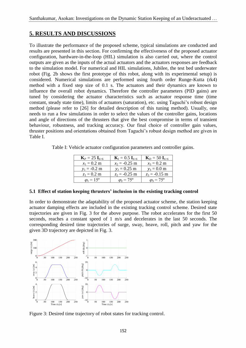
5.1 Effect of station keeping thrusters’ inclusion in the existing tracking control
In order to demonstrate the adaptability of the proposed actuator scheme, the station keeping
actuator damping effects are included in the existing tracking control scheme. Desired state
trajectories are given in Fig. 3 for the above purpose. The robot accelerates for the first 50
seconds, reaches a constant speed of 1 m/s and decelerates in the last 50 seconds. The
corresponding desired time trajectories of surge, sway, heave, roll, pitch and yaw for the
given 3D trajectory are depicted in Fig. 3.
Figure 3: Desired time trajectory of robot states for tracking control.

Santhakumar, Asokan: Investigations on the Dynamic Station Keeping of an Underactuated …
153
Figure 4: a) Variation in robot states for the inclusion of station keeping actuators;
b) Variation in actuator inputs for the inclusion of station keeping actuators.
The simulation results show that the proposed actuator configuration inclusion is not
much influencing (affecting) the existing tracking system performance. The variations of the
robot states and control inputs are given in Figs. 4a and 4b respectively. The errors are high
during acceleration and deceleration stages i.e., first and last 50 s. Control inputs (see Fig. 4b)
which are helping to overcome the inclusion effects of the station keeping thrusters are very
minimal (less than 0.015 N and 2.5º) and the error variations are less than 10 mm and 1º
in the positions and attitudes respectively.
5.2 Simple station keeping results in the presence of underwater current
The testing condition is chosen as: underwater current amplitude is 0.3 m/s, angle of attack
45º, side slip angle 45º, and the final desired positions (x, y and z) and angles (roll, pitch and
yaw) are taken as 1 m and 0º respectively. Robot desired positions are given as unit step input,
apart from this input the underwater current is acting on the robot which tries to drift the robot
in its desired states. This case is simulated and results are given in the Fig. 5, which shows
that the proposed configuration can compensate the underwater current effects and maintain
the robot in its desired states effectively. These results show that the actuator inputs are not
exceeding the design limits ( 1.0 kgf = 9.81 N) and the error trajectories are also
converging fast (within 30 to 40 s) towards their desired states.
Figure 5: Station keeping results for the proposed configuration with underwater current
(condition: Vc = 0.3 m/s, = 45º and = 45º).
a) b)

Santhakumar, Asokan: Investigations on the Dynamic Station Keeping of an Underactuated …
154
5.3 Hardware-in-the-loop simulation results in the presence of underwater current
The same previous operating condition has taken for the HIL simulation to confirm the
performance of the proposed scheme in the real time. The schematic layout of HIL simulation
is presented in Fig. 6. The results of the experiment are given in Fig. 7, which shows that the
proposed system can effectively keep the given desired coordinates in the presence of
uncertainties such as disturbances (underwater current). The comparative results of HILS
(detailed thrusters and control plane dynamics are considered in the simulation model) and
numerical simulations (which are given in Sec. 5.2) are given in Figs. 5 and 7, which
confirmed that the proposed actuator configuration can compensate the underwater currents
effectively. The settling time or steady state time (from HIL values), corresponding to
position errors of robot in the surge, sway and heave axes are 29.1 s, 23.9 s and 23.6 s (within
5 cm error limit) respectively, and corresponding to orientation errors in the pitch and yaw
axes are 24.7 s and 28.4 s (within 0.3º error limit). The time history of thrusters outputs are
given in Fig. 7, and from this, it is seen that these actuator values are not exceeding the design
limits ( 1.0 kgf = 9.81 N). HIL values are showing similar behaviour of the numerical
simulation values with noise effects. These noise effects are mainly due to the actuator
response delay, instrument noises and mechanical vibrations of the robot - actuator frame.
Figure 6: Schematic layout of HILS.
Figure 7: HIL simulation results for the proposed scheme with underwater current
(condition: Vc = 0.3 m/s, = 45º and = 45º).

Santhakumar, Asokan: Investigations on the Dynamic Station Keeping of an Underactuated …
155
5.4 Station keeping performance analysis under different underwater currents
In order to investigate the performance of the proposed configuration in the presence of
different underwater currents, there were four parameters have selected such as average
current velocity (Vc), angle of attack (), side slip angle () and net positive buoyancy (b).
The numerical simulations are carried out for current amplitudes varying from -0.5 m/s to
+0.5 m/s, in steps of 0.1 m/s, angle of attack and side slip angle are varying from –90º to +90º,
in steps of 5º and the robot net positive buoyancy is varying from 0 kgf to 0.5 kgf, in steps of
0.05 kgf. The tracking position and attitude errors are plotted in Figs. 8 to 9. These results
show that the proposed configuration is producing a much better performance and keeping the
robot at the desired coordinates. The maximum position errors, orientation errors and the
maximum thrust value are not exceeding 1 m, 2º and 6 N respectively which are within
the design limits. The heave position maximum overshoot is almost constant (nearly 1 m) for
the all the three cases except buoyancy variation plot (Fig. 8). This difference is common
phenomenon, since the buoyancy force always tries to push the robot up and the underwater
current is also acting in the same direction i.e., the robot getting more effect in the opposite to
the desired direction. This comprehensive study helps the design team to identify the possible
configuration and modification of the design at the initial stage.
Figure 8: Maximum values of position errors for different underwater currents.
Figure 9: Maximum values of attitude errors for different underwater currents.

Santhakumar, Asokan: Investigations on the Dynamic Station Keeping of an Underactuated …
156
6. CONCLUSIONS
In the paper, a series of performance analysis of station keeping control of an autonomous
underwater robot has been investigated. The influences and effects of underwater current
magnitudes and angle of incidences are analysed.
The simple structure, robustness and ease of computation of the proposed configuration
make it very attractive for real time implementation for dynamic positioning of underwater
robot. Station keeping actuators inclusion is not much affecting the original tracking control
and its performance, and variations (additional effects) in the control inputs are very minimal.
Simulation and hardware-in-the-loop simulation results show that the proposed scheme can
effectively maintain the given desired position in the presence of underwater currents and
uncertainties in hydrodynamic parameters. These simulation results will be very helpful to
study the underwater current effect on the underwater robot controller design and its
improvement.
The present PID controller is proved to have very good performance to control the
underwater robot in the underwater currents, and even good for the parameter uncertainties.
However, for the large current amplitudes and buoyancies, the present controller may cause a
serious directional instability on the robot; therefore the more robust controller may be needed
to improve the present control scheme. Experimental verification of the underwater robot
station keeping control will be taken up in the near future to validate the proposed scheme.
REFERENCES
[1] Blidberg, D. R.; Turner, R. M.; Chappell, S. G. (1991). Autonomous underwater vehicles:
Current activities and research opportunities, Robotics and Autonomous Systems, Vol. 7, 139-
150, doi:10.1016/0921-8890(91)90038-M
[2] Yuh, J. (2000). Design and control of autonomous underwater robots: A survey, Autonomous
Robots, Vol. 8, No. 1, 7-24, doi:10.1023/A:1008984701078
[3] Fossen, T. I. (1994). Guidance and Control of Ocean Vehicles, Wiley, Chichester
[4] Sen, D. (2000). A study on sensitivity of maneuverability performance on the hydrodynamic
coefficients for submerged bodies, Journal of Ship Research, Vol. 44, No. 3, 186-196
[5] Fossen, T. I. (2002). Marine Control Systems: Guidance, Navigation and Control of Ships, Rigs
and Underwater Vehicles, Marine Cybernetics, Trondheim, Norway
[6] Choi, S. K.; Yuh, J. (1996). Experimental Study on a Learning Control System with Bound
Estimation for Underwater Robots, Autonomous Robots, Vol. 3, No. 3, 187-194,
doi:10.1007/BF00141154
[7] Antonelli, G. (2007). On the use of adaptive / integral actions for six-degrees-of-freedom control
of autonomous underwater vehicles, IEEE Journal of Oceanic Engineering, Vol. 32, 300-312,
doi:10.1109/JOE.2007.893685
[8] Do, K. D.; Pan, J.; Jiang, Z. P. (2004). Robust and adaptive path following for underactuated
autonomous underwater vehicles, Ocean Engineering, Vol. 31, No. 16, 1967-1997,
doi:10.1016/j.oceaneng.2004.04.006
[9] Lapierre, L.; Soetanto, D. (2007). Nonlinear path-following control of an AUV, Ocean
Engineering, Vol. 34, No. 11-12, 1734-1744, doi:10.1016/j.oceaneng.2006.10.019
[10] Repoulias, F.; Papadopoulos, E. (2007). Planar trajectory planning and tracking control design
for underactuated AUVs, Ocean Engineering, Vol. 34, No. 11-12, 1650-1667,
doi:10.1016/j.oceaneng.2006.11.007
[11] Kumar, R. P.; Kumar, C. S., Sen, D.; Dasgupta, A. (2009). Discrete time-delay control of an
autonomous underwater vehicle: Theory and experimental results, Ocean Engineering, Vol. 36,
No.1, 74-81, doi:10.1016/j.oceaneng.2008.07.011

Santhakumar, Asokan: Investigations on the Dynamic Station Keeping of an Underactuated …
157
[12] Perrier, M.; Canudas-De-Wit, C. (1996). Experimental Comparison of PID vs. PID plus
Nonlinear Controller for Subsea Robots, Autonomous Robots, Vol. 3, No. 2-3, 195-212,
doi:10.1007/BF00141155
[13] Brutzman, D.; Doucy, O.; Healy, A. (2000). Near surface manoeuvring and station-keeping for
an autonomous underwater vehicle, Proceedings of the NATO symposium on Applied Vehicle
Technology, 1-10
[14] Koh, T. H.; Lau, M. W. S.; Seet, G.; Low, E. (2006). A control module scheme for an
underactuated underwater robotic vehicle, Journal of Intelligent and Robotic Systems, Vol. 46,
No. 1, 43-58, doi:10.1007/s10846-006-9052-6
[15] Liu, S.; Wang, D.; Poh, E. (2008). Output feedback control design for station keeping of AUVs
under shallow water wave disturbances, International Journal of Robust and Nonlinear Control,
Vol. 19, No. 13, 1447-1470, doi:10.1002/rnc.1387
[16] Lots, J. F.; Lane, D. M.; Trucco, E.; Chaumette, F. (2001). A 2D visual servoing for underwater
vehicle station keeping, Proceedings of the IEEE International Conference on Robotics and
Automation, 2767-2772
[17] Riedel, J. S. (2000). Shallow water station keeping of an autonomous underwater vehicle: The
experimental results of a disturbance compensation controller, Proceedings of the MTS/IEEE
Conference on OCEANS, 1017-1024
[18] Zwaan, S. V.; Bernardino, A.; Santos-Victor, J. (2002). Visual station keeping for floating robots
in unstructured environments, Robotics and Autonomous Systems, Vol. 39, 145-155,
doi:10.1016/S0921-8890(02)00200-2
[19] Marks, R. L.; Wang, H. H.; Lee, M. J.; Rock, S. M. (1994). Automatic visual station keeping of
an underwater robot, Proceedings of the MTS/IEEE Conference on OCEANS, Vol. 2, 137-142
[20] Negahdaripour, S.; Fox, J. (1991). Underwater optical station-keeping: improved methods,
Journal of Robotic Systems, Vol. 8, No. 3, 319-338, doi:10.1002/rob.4620080304
[21] Jin, L.; Xu, X.; Negahdaripour, S. (1996). A real-time vision-based stationkeeping system for
underwater robotics applications, Proceedings of the MTS/IEEE Conference on OCEANS, Vol. 3,
1076-1081
[22] Santhakumar, M.; Asokan, T. (2010). Planar dynamic station keeping of underactuated
autonomous underwater robot in the presence of underwater currents, Proceedings of the
International Symposium on Robotics and Intelligent Sensors, 84-89
[23] Alvarez, A.; Caffaz, A.; Caiti, A.; Casalino, G.; Gualdesi, L.; Turetta, A.; Viviani, R. (2009).
Folaga: A low-cost autonomous underwater vehicle combining glider and AUV capabilities,
Ocean Engineering, Vol. 36, No. 1, 24-38, doi:10.1016/j.oceaneng.2008.08.014
[24] Chyba, M.; Haberkorn, T.; Singh, S.B.; Smith, R. N.; Choi, S. K. (2009). Increasing underwater
vehicle autonomy by reducing energy consumption, Ocean Engineering, Vol. 36, No. 1, 62-73,
doi:10.1016/j.oceaneng.2008.07.012
[25] Fang, M. C.; Chang, P. E.; Luo, J. H. (2006). Wave effects on ascending and descending motions
of the autonomous underwater vehicle, Ocean Engineering, Vol. 33, 1972-1999,
doi:10.1016/j.oceaneng.2005.09.009
[26] Santhakumar, M.; Asokan, T. (2009). Application of robust design techniques for underwater
vehicle control, Proceedings of ISOPE Ocean Mining Symposium, 285-289
[27] Slotine, J. E.; Li, W. (1991). Applied Nonlinear Control, Prentice Hall, Inc., Englewood Cliffs
[28] Santhakumar, M.; Asokan T. (2010). Investigations on the hybrid tracking control of an
underactuated autonomous underwater robot, Advanced Robotics, Vol. 24, No. 11, 1529-1556,
doi:10.1163/016918610X512587