investigations on elastic behaviour of corrugated plates · investigations on . elastic behaviour...
TRANSCRIPT

International Journal of Scientific & Engineering Research Volume 4, Issue 5, May-2013 ISSN 2229-5518
IJSER © 2013
http://www.ijser.org
Investigations on Elastic Behaviour of
Corrugated Plates Lathi Karthi, C.G.Nandakumar
Abstract— The high inherent stiffness of corrugated profile along with high, strength to weight ratio, makes the corrugated plates a versatile construction material in marine structures, girders, decking, sheet piling, roofing, wall cladding and even as blast walls on offshore installations. Corrugated plates undergo bending due to transverse loading and buckling due to inplane compressive loads. Very few research publications are available in the strength prediction of corrugated plates under different load combinations and various boundary conditions. In many of the studies, the corrugated plates are approximated as orthotropic plates of uniform thickness but differ in the elastic properties along the two perpendicular directions. A parametric study on the strength of corrugated plates with varyinyg parameters viz., thickness, angle of corrugation and aspect ratio for various boundary conditions have been carried out using linear elastic analyses. Equations for maximum principal stress and maximum deflection for corrugated sheets subjected to various loadings with simply supported boundary condition are made available in non dimensional parameters based on the multivariable regression method.
Index Terms— Angle of corrugation, aspect ratio, corrugated plates, lateral loading, linear elastic analyses, maximum principal stress, parametric study.
—————————— ——————————
1 INTRODUCTION
ORRUGATED plates are used in the field of civil engineering, architecture, marine transportation, container body, sheet piling,
web plates in bridge girders etc. They are found in decking, roofing and sandwich plate structures.These are light, easy to form and can provide higher load carrying capacity than flat plates. They are shaped into alternate ridges and grooves. Corrugated plates are plates with inbuilt stiffness. Their higher depth due to the corrugations attribute to higher structural rigidity. The structural orthotropy of corrugated plates is due to their geometric configuration unlike the sandwich plate where it is due to the materi-al. Corrugated plates have higher stiffness to weight ratio and high strength to weight ratio. For a high performance structure, corrugated plates can be recommended because of the above special structural features and/properties and low fabrication cost. This paper presents the the parametric investigation into the linear elastic ehavior of corrugated plates with trapezoidal profile under variations in thickness, depth of corrugation and angle of corruga-tion,when they are subjected to various loadings with different boundary conditions. The stress analyses are done with the help of the software ANSYS, a finite element software, used extensively for linear and nonlinear analysis in the field of research. The validation of the analysis for corrugated plates using the software ANSYS was done with the re-sults published in the research paper of Liew et al6].
2 ORTHOTROPIC PLATE MODEL Corrugated plates have different flexural characteristics along the
two perpendicular directions. The theoretical analysis of corrugated plate is based on the assumption that it can be analysed as an equiva-lent thin orthotropic plate of uniform thickness. The governing dif-ferential equation[13] for orthotropic plates of thickness ‘h’ with E, G and υ as the Young’s modulus, shear modulus and Poisson’s ratio
respectively, is
(1) Where,
The number of elements and calculation time can be reduced by modeling the corrugated plate as two dimensional orthotropic plates. Samanta and Mukhopadhyay [10], Brassoulis [2], and Liew et al [6] have analytically derived extensional and flexural rigidities of corru-gated plates.
Classical Equations. In corrugated plate analysis, Seydel’s formula available with[1], [4] is considered to be classical expressions. Briassoulis[2], Easley[3], and Lau[4] have later modified these formulae after comparing the computation results from the expressions and precise analysis. Sa-manta [10], Briassoulis[2] derived new and more precise expressions for the extensional rigidity of trapezoidally corrugated plates. Many of the past studies reveal that the effect of transverse shear causes errors in the results. Various equations involved in the analysis of trapezoidally corrugat-ed plates subjected to different kinds of loads are given elsewhere [5],[7],[8],[9].
C
————————————————
Lathi Karthi, Research Scholar, Department of Ship Technology, Cochin University of Science and Technology, Kochi682022, India. E-mail: [email protected]
C.G. Nanadakumar, Associate Professor, Department of Ship Technology, Cochin University of Science and Technology, Kochi,682022, India. E-mail: [email protected]
),(24
4
22
4
4
4
yxpy
w
yx
wH
x
wDx
,12
,12
,12
,12
33
1
33 GhD
hED
hED
hED xy
y
yx
x
)1(,
)1(,2
221
EE
EEEDDH yxxy
127
IJSER
International Journal of Scientific & Engineering Research Volume 4, Issue 5, May-2013 ISSN 2229-5518
IJSER © 2013
http://www.ijser.org
3 LINEAR ELASTIC ANALYSIS
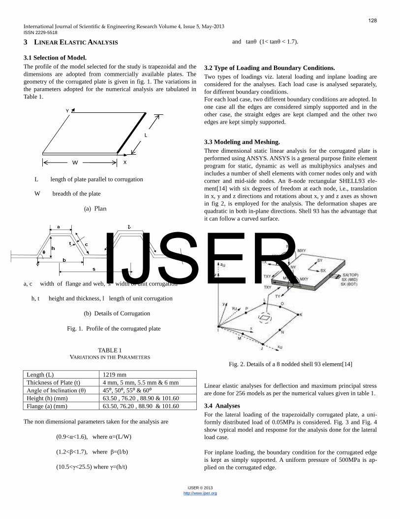
3.1 Selection of Model. The profile of the model selected for the study is trapezoidal and the dimensions are adopted from commercially available plates. The geometry of the corrugated plate is given in fig. 1. The variations in the parameters adopted for the numerical analysis are tabulated in Table 1.
L length of plate parallel to corrugation W breadth of the plate
(a) Plan
a, c width of flange and web, s width of unit corrugation
h, t height and thickness, l length of unit corrugation
(b) Details of Corrugation
Fig. 1. Profile of the corrugated plate
TABLE 1 VARIATIONS IN THE PARAMETERS
Length (L) 1219 mm Thickness of Plate (t) 4 mm, 5 mm, 5.5 mm & 6 mm Angle of Inclination (θ) 45⁰, 50⁰, 55⁰ & 60⁰ Height (h) (mm) 63.50 , 76.20 , 88.90 & 101.60 Flange (a) (mm) 63.50, 76.20 , 88.90 & 101.60
The non dimensional parameters taken for the analysis are (0.9<α<1.6), where α=(L/W)
(1.2<β<1.7), where β=(l/b)
(10.5<γ<25.5) where γ=(h/t)
and tanθ (1< tanθ < 1.7).
3.2 Type of Loading and Boundary Conditions. Two types of loadings viz. lateral loading and inplane loading are considered for the analyses. Each load case is analysed separately, for different boundary conditions. For each load case, two different boundary conditions are adopted. In one case all the edges are considered simply supported and in the other case, the straight edges are kept clamped and the other two edges are kept simply supported.
3.3 Modeling and Meshing. Three dimensional static linear analysis for the corrugated plate is performed using ANSYS. ANSYS is a general purpose finite element program for static, dynamic as well as multiphysics analyses and includes a number of shell elements with corner nodes only and with corner and mid-side nodes. An 8-node rectangular SHELL93 ele-ment[14] with six degrees of freedom at each node, i.e., translation in x, y and z directions and rotations about x, y and z axes as shown in fig 2, is employed for the analysis. The deformation shapes are quadratic in both in-plane directions. Shell 93 has the advantage that it can follow a curved surface.
Fig. 2. Details of a 8 nodded shell 93 element[14]
Linear elastic analyses for deflection and maximum principal stress are done for 256 models as per the numerical values given in table 1.
3.4 Analyses For the lateral loading of the trapezoidally corrugated plate, a uni-formly distributed load of 0.05MPa is considered. Fig. 3 and Fig. 4 show typical model and response for the analysis done for the lateral load case. For inplane loading, the boundary condition for the corrugated edge is kept as simply supported. A uniform pressure of 500MPa is ap-plied on the corrugated edge.
W
L
X
Y
128
IJSER

International Journal of Scientific & Engineering Research Volume 4, Issue 5, May-2013 ISSN 2229-5518
IJSER © 2013
http://www.ijser.org
Fig. 3. FE Model of corrugated sheet with lateral loading
Fig. 4. Transverse displacement for lateral loading
4 PARAMETRIC RESULTS
4.1 Formulation of Regression Equation. A fitted linear regression model can be used to identify the relation-ship between a single predictor variable xj and the response variable when all the other predictor variables in the model are “held
fixed”[11]. Each of the four independent variables is separately ana-lysed with the response variable. The regression analysis was done by using the software SPSS. The new formulae for predicting the deflection and stress are derived by using multi variable regression model. The general form of the multi variable regression equations for deflection and maximum principal stress are taken as given in equations (2) and (3).(YS is the
yield stress taken as 250MPa).
(2)
(3)
a) Lateral Loading. The four independent variables are separately analysed with the response variable viz. maximum deflection, ‘w’ and max-imum principal stress, ‘MPS’. Based on the regression analysis, the coefficients of the nondimensional parameters are substi-tuted in the proposed equations of deflection and MPS as giv-en in equations (4) and (5).
(4)
(5)
Values of deflection calculated using the formula is compared with the values obtained from FEM and the results are plotted as shown in the graph below. (Fig. 5.)
Fig. 5. Predicted Value vs. FEM value for deflection
θntanm
γl
βk
αt
w
θstanr
γq
βp
αYS
MPS
17.1
b
l
θ3.77tan
1.9
t
h3.76
W
L0.13
t
w
36.9
21.2tan
22.154.1
15.0
b
l
t
h
W
L
MPS
YS
129
IJSER
International Journal of Scientific & Engineering Research Volume 4, Issue 5, May-2013 ISSN 2229-5518
IJSER © 2013
http://www.ijser.org
The multiple coefficient of determination R2 can represent how well a multiple regression model fits a set of data.. R2 =0 indicates a com-plete lack of fit of the model to the data and R2 =1 implies a perfect fit of the model. In the analysis for deflection, the value of R2 is 0.94 implying that the proposed regression model fits well into the set of data.
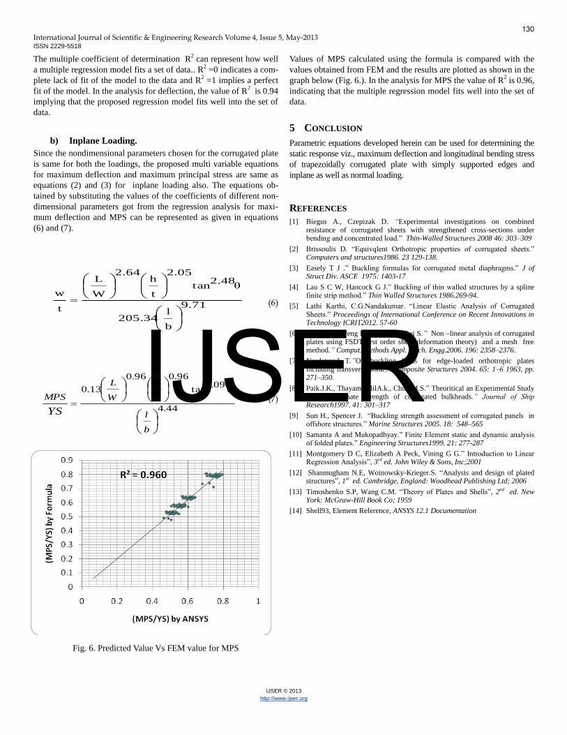
b) Inplane Loading. Since the nondimensional parameters chosen for the corrugated plate is same for both the loadings, the proposed multi variable equations for maximum deflection and maximum principal stress are same as equations (2) and (3) for inplane loading also. The equations ob-tained by substituting the values of the coefficients of different non-dimensional parameters got from the regression analysis for maxi-mum deflection and MPS can be represented as given in equations (6) and (7).
(6)
(7)
Fig. 6. Predicted Value Vs FEM value for MPS
Values of MPS calculated using the formula is compared with the values obtained from FEM and the results are plotted as shown in the graph below (Fig. 6.). In the analysis for MPS the value of R2 is 0.96, indicating that the multiple regression model fits well into the set of data.
5 CONCLUSION Parametric equations developed herein can be used for determining the static response viz., maximum deflection and longitudinal bending stress of trapezoidally corrugated plate with simply supported edges and inplane as well as normal loading.
REFERENCES [1] Biegus A., Czepizak D. “Experimental investigations on combined
resistance of corrugated sheets with strengthened cross-sections under bending and concentrated load.” Thin-Walled Structures 2008 46: 303–309
[2] Brissoulis D. “Equivqlent Orthotropic properties of corrugated sheets.” Computers and structures1986. 23 129-138.
[3] Easely T J .” Buckling formulas for corrugated metal diaphragms.” J of Struct Div. ASCE 1975: 1403-17
[4] Lau S C W, Hancock G J.” Buckling of thin walled structures by a spline finite strip method.” Thin Walled Structures 1986.269-94.
[5] Lathi Karthi, C.G.Nandakumar. “Linear Elastic Analysis of Corrugated Sheets.” Proceedings of International Conference on Recent Innovations in Technology ICRIT2012. 57-60
[6] Liew K.M., Peng L.X., Kitipornchai S.” Non –linear analysis of corrugated plates using FSDT(first order shear deformation theory) and a mesh free method.” Comput. Methods Appl. Mech. Engg.2006. 196: 2358–2376.
[7] Nordstrand T.”On buckling loads for edge-loaded orthotropic plates including transverse shear.” Composite Structures 2004. 65: 1–6 1963, pp. 271–350.
[8] Paik.J.K., ThayamballilA.k., Chun M.S.” Theoritical an Experimental Study on the Ultimate Strength of corrugated bulkheads.” Journal of Ship Research1997. 41: 301–317
[9] Sun H., Spencer J. “Buckling strength assessment of corrugated panels in offshore structures.” Marine Structures 2005. 18: 548–565
[10] Samanta A and Mukopadhyay.” Finite Element static and dynamic analysis of folded plates.” Engineering Structures1999. 21: 277-287
[11] Montgomery D C, Elizabeth A Peck, Vining G G.” Introduction to Linear Regression Analysis”, 3rd ed. John Wiley & Sons, Inc;2001
[12] Shanmugham N.E, Woinowsky-Krieger.S. “Analysis and design of plated structures”, 1st ed. Cambridge, England: Woodhead Publishing Ltd; 2006
[13] Timoshenko S.P, Wang C.M. “Theory of Plates and Shells”, 2nd ed. New York: McGraw-Hill Book Co; 1959
[14] Shell93, Element Reference, ANSYS 12.1 Documentation
9.71
b
l205.34
θ2.48tan
2.05
t
h2.64
W
L
t
w
44.4
09.1tan
96.096.0
13.0
b
l
t
h
W
L
MPS
YS
130
IJSER