investigations of stress corrosion cracking of spent … of stress corrosion cracking of spent fuel...
TRANSCRIPT

Investigations of Stress Corrosion
Cracking of Spent Fuel Dry Storage
Canisters Used for Long-Term Storage
IAEA International Conference on Management
of Spent Fuel From Nuclear Power Reactors
S.J. Saltzstein, D.G. Enos, C.R. Bryan, K.B. Sorenson
Sandia National Laboratories
19 June 2015
Vienna, Austria SAND2015-4430 C
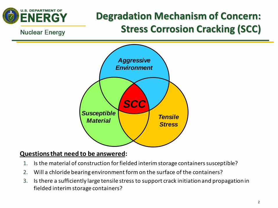
Degradation Mechanism of Concern: Stress Corrosion Cracking (SCC)
Questions that need to be answered:
1. Is the material of construction for fielded interim storage containers susceptible?
2. Will a chloride bearing environment form on the surface of the containers?
3. Is there a sufficiently large tensile stress to support crack initiation and propagation in fielded interim storage containers?
Aggressive
Environment
Susceptible
Material Tensile
Stress
SCC
2

Horizontal (e.g., Areva TN) Vertical (e.g., Holtec)
We Have Numerous Types of Dry Cask Systems.

Dry Casks are Located in Diverse Environments.
Many interim storage sites are located in marine environments where significant deposition of marine aerosols is anticipated
4

What is on the Surface Of Fielded Containers?
EPRI and the DOE have cooperated in an effort to view and sample the dust on the surface of the containers at three ISFSI sites
– Calvert Cliffs (with support from Areva TN) – Brackish water
– Hope Creek (with support from Holtec) – Brackish water
– Diablo Canyon (with support from Holtec) – Marine (Ocean)
Images from July 27, 2012, supplemental information letter submitted from CENG to the NRC (Adams document no. ML12212A216)
Surface of 19.5 yr old container at Calvert Cliffs
5

Both Wet And Dry Sampling Techniques Were Employed
Similar procedures were used at all three utilities
Dry sampling was accomplished via an abrasive pad rubbed on the container surface
Wet sampling was performed using a device known as the SaltSmart™
6

Calvert Cliffs – Horizontal Storage System
7

Calvert Cliffs
Water soluble salts:
30 minute leach with deionized water
Cations: Ca2+ >> Na+, Mg2
+, K+
Anions: SO42– >> NO3
– > Cl–
Salts do not appear to have a large marine component:
Low Na+, Cl–, high Ca2+, SO42–
Conversion after deposition via particle-gas conversion reactions? Does not explain low Na.
Preferential deposition of deliquesced Ca-Cl salts, followed by conversion to sulfates and chloride-loss?
8
From: C.R. Bryan, D.G. Enos “Understanding the Environment on the Surface of Spent Nuclear Fuel Interim Storage Containers”, SAND2013-8487C, October, 2013
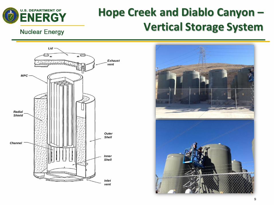
Hope Creek and Diablo Canyon – Vertical Storage System
9
Lid
MPC
Exhaust
vent
Inlet
vent
Radial
Shield
Outer
Shell
Inner
Shell
Channel

Typical Wet Sample Results Hope Creek
Solutions extracted from SaltSmart reservoir pads
– Soluble components largely calcium, sulfate, and nitrate
– Little chloride
Complicating factors
– Extraction efficiency in the field
– Pad to container contact patch variation
G.S. = Gamma Shield
From: C.R. Bryan, D.G. Enos “Analysis of Dust Samples Collected from Spent Nuclear Fuel Interim Storage Containers at Hope Creek, Delaware and Diablo Canyon, California”, SAND2014-16383, July, 2014
10

Typical Wet Sample Results Diablo Canyon
Solutions extracted from SaltSmart reservoir pads
– Sea salt aerosols of NaCl and Mg sulfate with trace amounts of K and Ca
Complicating factors
– Extraction efficiency in the field
– Pad to container contact patch variation
From: C.R. Bryan, D.G. Enos “Analysis of Dust Samples Collected from Spent Nuclear Fuel Interim Storage Containers at Hope Creek, Delaware and Diablo Canyon, California”, SAND2014-16383, July, 2014
Sample # Loc. Depth (cm) Temp (°C) Cl– (mg/m2)
123-003 Side 426 49 4.8
123-004 Side 350 79 3.6
123-005* Side 320 87 2
123-002 G.S. — 58
123-010 Blank — 25
170-007* Side 320 81 4.2
170-008* Side 289 84 2.9
170-009* Side 274 87 2.5
170-002 G.S. — — 13
Blank — — — 4.2
Blank — — — 2.3
Blank — — — 3.8
Blank — — — 1.5
*Wick adhered to silicone pad, and reservoir only partially saturated
11

Is There Going to be Sufficient Tensile Stress?
Is there sufficient residual stress within the container wall to support propagation of a through-wall crack?
Many complicating factors
– Weld procedure (start/stop, technique, etc.)
– Weld repairs
K. Ogawa, et al, “Measuring and Modeling of Residual Streses in Stainless Steel
Girth Welds”, PVP 2008 61542, July 27-31, 2008, Chicago, IL. L. Edwards, et al, “Direct Measurements of the Residual Stresses near a “Boat -
Shaped” repair in a 20mm Thick Stainless Steel Tube Butt Weld”, International
Journal of Pressure Vessels and Piping, 82 (2005), pp. 288-298
Tension
Compression
Tension
Compression
12

Full Scale Diameter Mock-Up Assembled to Directly Measure
Residual Stresses 1.7
1 m
three 1.22 m sections
Three
longitudinal
welds, 180
degrees
apart
Two Weld Repairs
Wall material: 304 SS welded with 308 SS
Wall thickness, overall diameter, weld joint geometry: standard geometry for NUHOMS 24P
Welds:
Full penetration and inspected per ASME B&PVC Section III, Division 1, Subsection NB (full radiographic inspection)
Double-V joint design, Submerged Arc welding process
What are we going to measure?
Weld residual stress state (deep hole drilling, contour measurement, x-ray diffraction)
Once analyzed, the container will be cut and used as samples for further analysis
13

Summary and Future Direction: Understand When and Where SSC may Occur
Large existing fleet of storage containers made from welded 304SS, located at both marine and inland sites
– Material known to be susceptible to SCC
– Chloride bearing salts likely in some locations
– Residual stresses at welds could be significant and tensile in nature
Moving Forward, research will focus on
– Understanding potential brine chemistry on container surface
– Quantifying residual stress state at welds and weld repairs in full scale mock-container
– Identify the most important parameters for evaluating canister SCC penetration times
– Develop Non-Destructive Analysis tools detect cracks.
– Exploring susceptibility of welded material to both localized corrosion and stress corrosion cracking initiation and propagation
14

Acknowledgements
At Sandia National Labs
– David Enos – Corrosion Chemistry
– Charles Bryan – Brine chemistry and its evolution
– Kirsten Norman, Sam Lucero – Sample preparation and analysis
EPRI
– John Kessler and Keith Waldrop – ISFSI inspections/sample collection
– Shannon Chu – CISCC Task group
Industry
– Laszlo Zsidai (Holtec) – sampling at Hope Creek and Diablo Canyon
– Bill Bracey (Areva-TN) – sampling at Calvert Cliffs
15

THANK YOU
16