investigation report - international civil aviation … german federal bureau of aircraft accident...
TRANSCRIPT

Identification
Kind of occurrence: Serious Incident
Date: 1 March 2008
Location: Hamburg
Type of aircraft Commercial Air Transport
Manufacturer / Model Airbus / A320-211
Injuries to Persons: None
Damage to Aircraft: Minor damage
Other Damage: None
Source of Information: Investigation by BFU
German Federal Bureau of Aircraft Accident Investigation
Investigation Report 5X003-0/08 March 2010
mail: [email protected] http:// www.bfu-web.de Tel: 0 531 35 48 0 Fax: 0 531 35 48 246
Editor/Distribution: Bundesstelle für Flugunfalluntersuchung Hermann-Blenk-Str. 16 38108 Braunschweig

Identification
Kind of occurrence: Serious Incident
Date: 1 March 2008
Location: Hamburg
Type of aircraft Commercial Air Transport
Manufacturer / Model: Airbus / A320-211
Injuries to persons: None
Damage to Aircraft: Minor Damage
Other Damage: None
Source of Information: Investigation by BFU
This investigation was conducted in accordance with the Federal German Law Relating to the Investigation into Accidents and Incidents Associated with the Operation of Civil Aircraft (Flugunfall-Untersuchungs-Gesetz - FlUUG) of 26 August 1998. The sole objective of the investigation is to prevent future accidents and incidents. The in-vestigation does not seek to ascertain blame or apportion legal liability for any claims that may arise. The present document is the translation of the German Investigation report. Although efforts are made to translate it as accurate as possible, discrepancies may occur. In this case the German version is authentic.
Investigation Report 5X003-0/08 March 2010
German Federal Bureau of Aircraft Accident Investigation
mail: [email protected] http:// www.bfu-web.de Tel: 0 531 35 48 0 Fax: 0 531 35 48 246
Editor/Distribution: Bundesstelle für Flugunfalluntersuchung Hermann-Blenk-Str. 16 38108 Braunschweig
BFU German Federal Bureau of Aircraft Accident Investigation
5X003-0/08 I
Contents
Abbreviations...............................................................................................................................................1
Summary ......................................................................................................................................................3
1. Factual Information......................................................................................................................4 1.1 History of the flight .........................................................................................................................4 1.2 Injuries to persons..........................................................................................................................7 1.3 Damage to aircraft..........................................................................................................................7 1.4 Other damage ................................................................................................................................7 1.5 Personnel information ....................................................................................................................7 1.5.1 Pilot-in-command ...........................................................................................................................7 1.5.2 Co-pilot ...........................................................................................................................................7 1.5.3 Aerodrome controller......................................................................................................................8 1.5.4 Ground control ...............................................................................................................................8 1.6 Aircraft information .........................................................................................................................8 1.7 Meteorological information...........................................................................................................12 1.8 Aids to Navigation ........................................................................................................................21 1.9 Communications ..........................................................................................................................21 1.10 Aerodrome Information ................................................................................................................21 1.11 Flight Recorders...........................................................................................................................21 1.12 Wreckage and impact information ...............................................................................................22 1.13 Medical and pathological information...........................................................................................23 1.14 Fire ...............................................................................................................................................23 1.15 Survival aspects ...........................................................................................................................23 1.16 Tests and research ......................................................................................................................23 1.17 Organisational and management information..............................................................................23 1.17.1 Air operator company...................................................................................................................23 1.17.2 Air Traffic Control .........................................................................................................................24 1.17.3 German Meteorological Service...................................................................................................24 1.18 Additional Information ..................................................................................................................26 1.18.1 Flight Manuals..............................................................................................................................26 1.18.2 Operational instructions for the flight crew...................................................................................28 1.18.2.1 Operations Manual Part A (OM/A) ...............................................................................................28 1.18.2.2 Operations Manual Part B (OM/B) ...............................................................................................29 1.18.2.3 Operations Manual Part C (OM/C)...............................................................................................30 1.18.2.4 Operations Manual Part D (OM/D)...............................................................................................30 1.18.3 Operational Instructions contained in the aircraft manufacturer's documentation.......................31 1.18.3.1 Flight Crew Operating Manual .....................................................................................................31 1.18.3.2 Airbus A318/A319/A320/A321 Flight Crew Training Manual (FCTM) .........................................31 1.18.3.3 Airbus A318/A319/A320/A321 FCOM-Bulletin No. 828/1............................................................32 1.18.3.4 Airbus A318/A319/A320/A321 FCOM-Bulletin No. 827/1............................................................32 1.18.3.5 Flight Operations Briefing Note (FOBN) "Landing Techniques Crosswind Landings".................33 1.18.4 Crosswind landing operational limitations....................................................................................35

BFU German Federal Bureau of Aircraft Accident Investigation
5X003-0/08 II
1.18.4.1 FCOM Airbus A319/A320/A321 ...................................................................................................35 1.18.4.2 OM/B Quick Reference Handbook...............................................................................................35 1.18.4.3 OM/A Operating Manual (crosswind)...........................................................................................35 1.18.5 Aircraft type certification...............................................................................................................35 1.18.5.1 Type Certificate ............................................................................................................................35 1.18.6 The Tasks of the air traffic controller (Tower) ..............................................................................37 1.18.7 Noise abatement at Hamburg Airport ..........................................................................................37 1.19 Useful or effective investigation techniques.................................................................................39 1.19.1 Analysis of the flight sequence by the aircraft manufacturer .......................................................39 1.19.2 Anonymous questionnaire survey of airline pilots........................................................................43
2. Analysis ......................................................................................................................................45 2.1 Operational aspects and history of the flight................................................................................45 2.1.1 Analysis of the flight from the operational viewpoint....................................................................45 2.1.1 Results - Analysis of the results by the aircraft manufacturer......................................................47 2.2 Specific Conditions.......................................................................................................................47 2.2.1 Flight Crew and Flight Operations ...............................................................................................47 2.2.2 Air traffic controllers .....................................................................................................................49 2.2.3 Decision-taking processes ...........................................................................................................49 2.2.3.1 Pre-flight preparation....................................................................................................................49 2.2.3.2 Choice of landing direction...........................................................................................................50 2.2.3.3 Go-around ....................................................................................................................................51 2.2.3.4 Alternate diversion airports ..........................................................................................................52 2.2.3.5 Approach and Landing to Runway 33..........................................................................................52 2.2.4 Aircraft design-dependent system behaviour (Control Laws) ......................................................53 2.2.5 Weather........................................................................................................................................54 2.3 Defences ......................................................................................................................................56 2.3.1 The air operator's crosswind landing requirements .....................................................................56 2.3.2 The aircraft manufacturer's requirements for crosswind landings ...............................................56 2.3.3 Demonstration of compliance during type certification (Certification Specification) ....................57 2.3.4 Manufacturer's description of crosswind landing procedures ......................................................58 2.3.5 The Air Operator's description of crosswind landing procedure ..................................................59 2.4 Organisational aspects.................................................................................................................61
3. Conclusions................................................................................................................................62 3.1 Findings........................................................................................................................................62 3.2 Causes .........................................................................................................................................66
4. Safety Recommendations .........................................................................................................66
5. Appendices.................................................................................................................................71

BFU German Federal Bureau of Aircraft Accident Investigation
5X003-0/08 Seite 1
Abbreviations
FM Flughandbuch Flight Manual
AIP Luftfahrthandbuch Aeronautical Information Publication
AMDAR Aircraft Meteorological Data Relay
AOC Luftverkehrsbetreiberzeugnis Air Operator Certificate
ATIS Automatische Informationsdurchsage Automatic Terminal Information Service
ATPL(A) Lizenz für Verkehrspiloten Airline Transport Pilot License
BA-FVK Betriebsanweisung für den Flug-verkehrskontrolldienst
Manual of Operations for the Air Traffic Control Service
BAO Betriebsanordnung Company Directive for the Air Traffic Control Service
BFU Bundesstelle für Flugunfallunter-suchung
Federal Bureau of Aircraft Accident Investigation
CPL(A) Lizenzen für Berufspiloten (Flugzeuge) Commercial Pilot Licence (Aeroplane)
CRM Crew Resource Management
CTR Kontrollzone Control Zone
CVR Cockpit Tonaufzeichnungsgerät Cockpit Voice Recorder
DFDR Digitaler Flugdatenschreiber Digital Flight Data Recorder
DWD Deutscher Wetterdienst German Meteorological Service Provider
EASA Europäische Agentur für Flugsicherheit European Aviation Safety Agency
ELAC Elevator-Aileron-Computer
EU-OPS Europäisches Regelwerk European Regulation
FAC Flight-Augmentation-Computer
FCOM Flight Crew Operating Manual
FCTM Flight Crew Training Manual
FIR Fluginformationsgebiet Flight Information Region
FIUUG Flugunfalluntersuchungsgesetz
FL Flugfläche Flight Level
FM Flughandbuch Flight Manual
FOBN Operating Briefing Notes

BFU German Federal Bureau of Aircraft Accident Investigation
5X003-0/08 Seite 2
GAMET Gebietswettervorhersage Area Forecast for Low Level Flights
IDVS Informationsdatenverarbeitungssystem
ILS CAT-II/III Instrumentenlandesystem Betriebsstufe II/III
Instrument Landing System Category II/III
JAR 25 Vorschrift für die Zulassung von Verkehrsflugzeugen (CS 25)
Airworthiness Standards for Large Aircraft (CS25)
JAR-OPS 1 Betriebsvorschriften für die gewerbs-mäßige Beförderung in Flugzeugen (heute: EU-OPS)
Standards for the Operation of Commercial Transportation by Aeroplane
LGCIUs Landing Gear Control Unit Interface
LOC / GS Localizer / Glideslope Landekurs / Gleitweg
MCC Multi Crew Concept
METAR Routinewettermeldungen Aviation Routine Weather Report
OM/A Betriebshandbuch, Teil A Operations Manual Part A
OM/B Betriebshandbuch, Teil B Operations Manual Part B
OM/C Betriebshandbuch, Teil C Operations Manual Part C
OM/D Betriebshandbuch, Teil D Operations Manual Part D
PF Luftfahrzeugführer am Steuer Pilot Flying
PNF Pilot non Flying
RWY Piste Runway
SEC Spoiler-Steuerung Spoiler-Elevator-Computer
SIGMET Signifikante Wetterinformation Significant Meteorological Information
TAF Flugplatzwettervorhersage Aerodrome Forecast
UIR Oberes Fluginformationsgebiet Upper Flight Information Region
VOLMET-System
Wetterinformation für Luftfahrzeuge im Flug
Meteorological Information for Aircraft in Flight
BFU German Federal Bureau of Aircraft Accident Investigation
5X003-0/08 Seite 3
Summary
At 1630 hrs1 on 1 March 2008, the German Federal Bureau of Aircraft Accident Investigation (BFU) was advised by Hamburg Airport that the left wing of an Airbus A320 had made contact with the ground during an attempted landing. In conformity with the Federal German Law Relating to the Investigation into Accidents and Incidents Associated with the Operation of Civil Aircraft (Flugunfall-Untersuchungs-Gesetz - FlUUG), this event was investigated as a ‘Serious Incident’.
Because of the weather associated with hurricane Emma, on 1 March 2008 the Airbus A320 left Munich Airport on a scheduled flight to Hamburg at 1231hrs about two hours behind schedule, with a crew of five and 132 passengers. Given the ATIS weather report including wind of 280°/23 kt with gusts of up to 37 kt, during the cruise phase of the flight the crew decided on an approach to Runway 23, the runway then also in use by other traffic. During the approach to land, the aerodrome controller gave several updates on the wind. Immediately prior to touchdown, the wind was reported as 300°/33 kt, gusting up to 47 kt. At the time of the decrab-procedure there was no significant gust.
The initial descent was flown by autopilot and the co-pilot assumed manual control from 940 ft above ground.
After the aircraft left main landing gear had touched down, the aircraft lifted off again and immediately adopted a left wing down attitude, whereupon the left wingtip touched the ground. The crew initiated a go-around procedure. The aircraft continued to climb under radar guidance to the downwind leg of runway 33, where it landed at 1352 hrs. No aircraft occupants were injured. The aircraft left wingtip suffered damage from contact with the runway.
This serious landing incident took place in the presence of a significant crosswind and immediate causes are as follows:
• The sudden left wing down attitude was not expected by the crew during the landing and re-sulted in contact between the wingtip and the ground.
• During the final approach to land the tower reported the wind as gusting up to 47 knots, and the aircraft continued the approach. In view of the maximum crosswind demonstrated for landing, a go-around would have been reasonable.
The following systematic causes led to this serious incident:
• The terminology maximum crosswind demonstrated for landing was not defined in the Operating Manual (OM/A) and in the Flight Crew Operating Manual (FCOM), Vol. 3, and the description given was misleading.
• The recommended crosswind landing technique was not clearly described in the aircraft standard documentation.
• The limited effect of lateral control was unknown.
1 Unless otherwise specified, all times are indicated in local time

BFU German Federal Bureau of Aircraft Accident Investigation
5X003-0/08 Seite 4
1. Factual Information
1.1 History of the flight
The Airbus A320 was on a scheduled flight from Munich to Hamburg with 132 passengers and a crew of five. The Munich departure time was scheduled for 1035 hrs1, but was delayed for about two hours by freezing rain. The general weather pattern over Germany was determined by the 'Emma' low-pressure system. The meteorological briefing provided to the flight crew included a westerly wind forecast, with gusts of up to 55 kt.
The flight crew reported the cruise phase as uneventful. They obtained current weather reports for the destination airport Hamburg, and the current weather for Frankfurt and Berlin-Tegel airports.
At 1317:29 hrs the aircraft was descending to Flight Level (FL) 80 and the crew established contact with Bremen Radar. After identifying the aircraft, the Air Traffic Controller advised: "….radar contact, information Whiskey, ILS two three". After advising the crew to reduce speed to 250 kt, the aircraft continued with radar vectors and descent instructions for the final approach to Hamburg.
At 1323:16 hrs there was a direct coordination discussion between Hamburg Tower and Bremen Radar, in which the Hamburg aerodrome controller reported the wind direction as 290°, and that Runway 33 was also available on request.
At 1327:48 hrs the controller issued a clearance for an ILS-Approach to Runway 23. In response to the controller's request, at 13:29:31 the flight crew reported the wind displayed in the cockpit instrumentation as 310°/60 kt. At this time, the Cockpit Voice Recorder (CVR) recorded a discussion about the wind between the flight crew, and the Captain's observation that a go-around could become necessary but should not be a problem.
At 1329:56 hrs, the crew changed frequency to Hamburg Tower and reported: "…..established ILS runway two three." The Hamburg aerodrome controller passed the current wind to the crew as: " …. wind three hundred two eight knots gusting four seven knots." The captain asked Hamburg Tower for the current go-around rate and was told "about fifty percent in the last ten minutes", and reported the current wind as 300°/ 28 – 47 kt. The aerodrome controller offered runway 33 as a possible option for a second approach. The captain informed that the crew would first attempt an approach to Runway 23. At 1332:01hrs the Hamburg aerodrome controller issued clearance to land on Runway 23 and reported the wind as 290°/ 29 kt, gusting 47 kt.
After lowering the landing gear and setting the flaps ("Flaps FULL") the aircraft crossed the outer marker and the flight crew had the runway in sight.
The approach down to 940 ft above ground level was flown with autopilot and autothrust selected, at which point the co-pilot took the controls, as previously arranged for this flight.
The captain reported that, bearing the current wind in mind, the final approach was very stable and flown under full control. At about the point when the aircraft crossed the runway threshold, he gave the co-pilot advice on the sink rate and thrust power settings. In his opinion, both parameters were stable, and the crab angle into wind seemed appropriate.
The flight crew reported that after the co-pilot had eliminated the crab angle by application of rudder, the right wing lifted shortly before touchdown. Commensurately, the left wing lowered and touched the ground. This ground contact was not detected by the flight crew, but was recorded on video film.
1 Unless stated to the contrary, all times are local

BFU German Federal Bureau of Aircraft Accident Investigation
5X003-0/08 Seite 5
The Flight Data Recorder (FDR) detected contact between the left main landing gear and the ground at 1333:33 hrs. At 13:33:35 the FDR registered 23° left roll. (Appendix 5).
At 1333:33 hrs and again two seconds later, the CVR recorded the sounds of touchdown. After the second touchdown sound, the co-pilot gave the order "Go-Around" and operated the engine thrust levers. The captain assumed control with the order: "Go-Around – I have control". After pressing the "TAKE OVER PUSHBUTTON", he continued the go-around procedure as Pilot Flying.
The aerodrome controller then instructed a change of frequency to 124.22 MHz and a Standard Missed Approach. The Captain handed over control of the aircraft to the co-pilot and informed the passengers of the delay via the PA system.
At 1334:55 hrs the A320 crew contacted Bremen Radar and received climb instructions and radar vectors. About three minutes later the radar controller advised that an Embraer crew on the ground at Hamburg Airport had witnessed apparent contact between the Airbus left wing and the ground. However, an inspection of the runway had found nothing untoward. At 1342:22 hrs the air traffic controller issued clearance for a Localizer-DME approach to Runway 33.
At 1345:24 hrs the Airbus crew again made contact with Hamburg Tower and reported as being on approach to Runway 33; the aerodrome controller reported the wind as 300°/27 gusting 50 kt. At 1346:46 hrs the aerodrome controller gave clearance to land on Runway 33, together with the current wind report as 300°/33 gusting 50 kt.
The aerodrome controller gave revised wind reports at 1348:29 hrs, 1349:08 hrs, 1350:06 hrs and 1350:29 hrs (300°/33 gusting 50; 290°/32 gusting 49; 290°/28 gusting 49; and 290°/27 gusting 49 kt).
At 1352 hrs the A320 landed on Runway 33. None of the occupants was injured. The aircraft had suffered damage to the left wingtip.

BFU German Federal Bureau of Aircraft Accident Investigation
5X003-0/08 Seite 6
Diagram 1: Flight track and ATC wind reports Source: BFU
Pre-flight preparation
The aircraft was prepared for flight and accepted by the crew in Düsseldorf for a flight to Munich. It was refuelled and laden with ballast in accordance with "Supplementary Procedure Handling of A/C on the ramp in strong wind".
In their reports to the BFU both members of the cockpit crew emphasized that they had been well aware of the general meteorological situation over Germany on 1 March 2008, and the high wind warnings given by the German Meteorological Service (DWD) via the media the previous day. This had formed an essential part of their personal pre-flight preparations.
The flight crew said that most of the pre-flight preparation for the sector Munich to Hamburg had been undertaken on the ground in Munich. They had analysed the wind situation in Hamburg, from which they had drawn the conclusion that a landing on Runway 23 with Instrument Landing System (LOC/GS) was the preferred option.
The crew said that during the approach to Munich they had discussed the wing flap settings at length and reached the conclusion that "Flaps FULL" was the preferred option under the current weather conditions. This discussion formed the basis for their subsequent decision to adopt the same configuration for the approach to Hamburg.
Crew Coordination / Crew Resource Management (CRM)

BFU German Federal Bureau of Aircraft Accident Investigation
5X003-0/08 Seite 7
The flight crew flew together for the first time on 1 March 2008. Both pilots had arrived in Düsseldorf early that morning from Frankfurt, to fly the first service from Düsseldorf to Munich.
In reply to questions put to him by the BFU, the Captain emphasized that he placed great importance on the high standard and efficiency of the cockpit crew in the execution of their duties during this flight. In line with the company's CRM policy, he had sought to maintain open crew communications on an equal level. Cockpit duties between himself and the co-pilot had been absolutely straightforward right from the beginning. He rated her as a confident co-pilot, with good self-assessment and commensurate self-assurance; a co-pilot who would not hesitate to state her thoughts, make appropriate observations, and accept advice.
The captain flew the sector from Düsseldorf to Munich as the pilot flying (PF). The crew agreed that the co-pilot would be the pilot flying on the subsequent flight from Munich to Hamburg. In the interview with the BFU the captain explained his subsequent decision not to alter the previously agreed flight crew tasks. His intention had been to make optimum use of flight crew resources on the flight to Hamburg, because he judged the approach to Hamburg as demanding. Both, during the flights from Düsseldorf to Munich and from Munich to Hamburg, his belief was confirmed that the co-pilot would hand over manual control of the aircraft or initiate a go-around if the approach was not correctly stabilized, or was outside the correct parameters. By acting as PNF (pilot non-flying), the captain had more capacity to deal with air traffic control, monitor aircraft attitude and performance, any weather changes and monitor the operation.
Prior to the flight, the crew had discussed and agreed the need to give each other early advice and support by comparing their observations throughout the course of the flight.
1.2 Injuries to persons
Nobody was injured as a result of this occurrence.
1.3 Damage to aircraft
The aircraft was slightly damaged.
1.4 Other damage
There was no other damage to persons or property
1.5 Personnel information
1.5.1 Pilot-in-command
The 39 year-old commander had an Air Transport Pilot's License (ATPL(A)) issued in accordance with JAR-FCL (German) with type rating as pilot in command for the Airbus A318/319/320/321. His license was valid for instrument flight rules and category III landings. His total flight time was 10,203 hours, of which 4,123 hours were in the aircraft type in question.
On the day in question, he had been on duty for eight hours, and had been off duty for the previous 47 hours.
1.5.2 Co-pilot
The 24 year-old co-pilot had a Commercial Pilot's License (CPL(A)), issued in accordance with JAR-FCL (German). She had a type rating as co-pilot for Airbus A318/319/320/321.Her license was also valid for instrument flight rules and category III landings. Her total flight time was 579 hours, of which 327 hours were on the aircraft type in question.

BFU German Federal Bureau of Aircraft Accident Investigation
5X003-0/08 Seite 8
On the day in question, she had been on duty for eight hours, and had been off duty for more than 60 hours.
1.5.3 Aerodrome controller
The 39 year-old aerodrome controller was in possession of an Air Traffic Controller's license with Airport Radar Approach and Flight Information Service (FIS) ratings. She had worked in the air traffic service provider company since 1992 and was cleared for PL1/2 and PB duties.
On the day in question, she had started work at 1225 hrs, prior to which she had been off duty for more than 48 hours.
1.5.4 Ground control
The 27 year-old ground controller had an Air Traffic Control license with ratings for Airfield Radar with Flight Information Service. She had worked in the air traffic service provider company since 2001 and was cleared for PL1/2 and PB duties.
On the day in question, she had started work at 1225 hrs, prior to which she had been off duty for more than 48 hours
1.6 Aircraft information
The A320 Airbus is the base model of the A320 family, which also includes the A318 and A319 with shortened fuselages and the stretched-fuselage A321.
The Type Certificate was issued in 1988 by the French Civil Aviation Authority, the Direction Générale de l’Aviation Civile (DGAC). The aircraft in question is an A320–211 Airbus built in 1992. The fuselage of this variant is 37.57 m long and the wingspan 34.10 m. The aircraft has a gross take-off weight of 73,500 kg and the Air Operator had fitted it with 150 seats.
Diagram 2: Three-view drawing Airbus A320 Source: Airbus

BFU German Federal Bureau of Aircraft Accident Investigation
5X003-0/08 Seite 9
The twin-jet A320 is a low-wing medium-range aircraft with a forward-retracting nose gear, and two wing-mounted main landing gears that retract inwards towards the fuselage. Each landing gear has two wheels side-by-side with gas spring-aided hydraulic shock absorbers.
The A320 flight controls are linked to the control surfaces (elevator, horizontal stabilizer, ailerons and spoilers) by an electrical 'Fly-By-Wire' system issuing commands to hydraulic actuators. The rudder hydraulic actuators are operated by mechanical linkage to the pilots' rudder pedals. In addition, there is a mechanical backup–system for the rudder and horizontal stabilizer. Primary control of the aircraft is by means of seven computers:
• Two Elevator-Aileron-Computers (ELAC); these control the elevator, aileron and horizontal-stabilizer.
• Three Spoiler-Elevator-Computers (SEC); these control the spoilers and are in constant standby readiness for control of the elevator and horizontal-stabilizer.
• Two Flight-Augmentation-Computers (FAC); these regulate electrical operation of the rudder.
Sidesticks
Each pilot has a cockpit sidestick to give manual pitch and roll commands; the two sidesticks have no mechanical linkage with each other. A sidestick command input is converted into an electrical signal then conveyed to the appropriate computers. If both sidesticks are simultaneously deflected, the command inputs are added arithmetically, and are limited by the maximum possible deflection of a single sidestick.
If a pilot wishes to assume control of the aircraft, he or she needs to operate the “Takeover Pushbutton“ on the sidestick. If the button is released within 30 seconds, both sidesticks return to the equal authority mode and the command signals of both are added up again. If the “Takeover Pushbutton” is continually depressed for more than 30 seconds, command priority is assumed by this sidestick. This priority can only be cancelled by renewed operation of the “Takeover Pushbutton“ particular on the other side.
BFU German Federal Bureau of Aircraft Accident Investigation
5X003-0/08 Seite 10
Control Laws
The Control Laws describe the way in which the flight control computers process deflection commands to the control surfaces, plus the associated monitoring and protective functions. In normal operations, the laws are: Normal Law, Alternate Law und Direct Law.
1. Normal Law applies during the entire flight, provided that there is no serious systems disruption of the flight control system. All the protective functions (load factor limit, pitch attitude protection, high angle of attack protection, high speed protection and bank angle protection) are active.
Sidestick input during Normal Law results vertically in a G-Load Demand and laterally in a roll rate demand.
2. Alternate Law applies if there should be any disruption of particular systems in the aircraft flight control system system or in systems which provide some of the data used by the aircraft flight control system. The aircraft remains fully manoeuvrable, and has lost part of the protective func-tions.
In Alternate Law sidestick input results vertically in a G-Load Demand whereas laterally there is a direct proportional relationship between sidestick deflection and deflection of the flight controls.
3. Direct Law: The aircraft is flown without any of the protective functions of Normal Law, basically similar to the old generation aircraft. There is a direct relationship between sidestick input and control surface deflection.
The three Control Laws result in different Flight Modes, application depending upon the respective flight phase (diag. 3).
During the operation of Normal Law, the preconditions for switchover to individual modes in vertical control depend upon vertical control (rotation about the transverse axis, pitch) and horizontal control (rotation about the longitudinal and vertical axes, lateral) and a number of specific conditions. Further, not all protective functions are available in all modes.
In the Flight Mode, all protective functions operate with respect to pitch control; however, during the Flare Mode the protection is reduced to high angle of attack protection; no protection at all exists in the Ground Mode.
When operating in the Flight Mode, the lateral control system incorporates active bank angle protection, which is deactivated in the Ground Mode.
Lateral Law is a mixture of roll and yaw demand with automatic turn coordination.

BFU German Federal Bureau of Aircraft Accident Investigation
5X003-0/08 Seite 11
Diag. 3: Flight Control Normal Laws Source: FCOM A320
Control Law changes on landing (Flight/Ground Transition)
During the final approach and landing, a predetermined logic sequence switches pitch control from Flight Mode to Flare Mode, and then to Ground Mode.
In Normal Law the lateral control switches from Flight Mode direct to the Ground Mode.
In order to allow the lateral control to change from Flight Mode to Ground Mode, a ground signal is required from the ELAC (Elevator and Aileron Computer). The Ground Signal is generated when:
• Both LGCIUs (Landing Gear Control Interface Unit) detect that one landing gear has been low-ered and is under load, and the radio altimeter measures the height above ground as less than 50 ft;
or
• the Ground Spoilers have been deployed, and the radio altimeter measures the height above ground as less than 50 ft;
or
• the LGCIU 1 and LGCIU 2 detect that the left and right main landing gears have been lowered and are under load;

BFU German Federal Bureau of Aircraft Accident Investigation
5X003-0/08 Seite 12
or
• at least one LGCIU detects that the left and right main landing gears have been lowered and are under load, and that the radio altimeter measures the height above ground as less than 50 ft .
When the respective ELAC unit has detected that the aircraft has touched down, within 0.5 seconds the system changes from Lateral Flight Law to Lateral Ground Law. The effect of this is:
• to cancel the aircraft feedbacks used in flight for the computation of ailerons / spoilers deflection, this one being only made using sidestick orders information,
• to limit the ailerons and roll spoilers 2, 3 and 4 deflection by about a half at high speed (Vc > 80 kt)”
When the aircraft operates under Direct Law, the protective functions provided under Normal Law (load factor limitation, pitch attitude protection, etc.) are de-activated.
After a normal take-off or an aborted landing procedure, the flight control system switches to Flight Mode within five seconds of the pitch surpassing 8°, following which all the protection functions are active.
During this investigation, the manufacturer stated that the system switches from Flight Mode to Ground Mode as soon as one main landing gear touches the ground, and that the effect of aileron deflection commands is reduced by a half.
Windcalculation by the Air Data Inertial Reference System
Wind speed and direction is calculated by the Air Data Inertial Reference System and is shown in the cockpit on the Navigation Display (ND). According to the aircraft manufacturer this calculated wind information is inaccurate and operationally unsuitable by wind speeds below 50 kt and by landings under crosswind influence.
1.7 Meteorological information
As part of the investigation into this serious incident, the BFU asked the German Meteorological Service (DWD) for an official aviation weather report.
General weather pattern and subsequent development
The DWD reported that the A320 route was through a zone subject to the effects of a powerful depres-sion. During the course of the day, the depression developed to hurricane strength and shifted from the Faeroe Islands towards southern Sweden. The associated rapidly occluding frontal system had reached central Germany at about 0700 hrs, preceded in the early morning by widespread heavy showers and active thunderstorm cells. In places the surface wind strength reached 10 to 12 on the Beaufort scale. At cruise altitude, the rear side of the occlusion had a vigorous north-westerly flow of unstable stratified maritime air; in the course of the day, the occlusion was repeatedly followed by lines of squalls.
At 1320 hrs the weather observation station at Hamburg-Fuhlsbüttel (EDDH) reported horizontal visibility of 9 km at surface level, light rain (-SHRA) and the main cloud base at 1,400 ft AGL. At about 1350 hrs the horizontal visibility at ground level was 8 km and the main cloud base was at 2,000 ft AGL.
Wind at the time of the incident
Surface Wind
The surface wind was measured by DWD anemometers located near to the thresholds of Runways 23/33 and 15 and logged at ten-second intervals.
BFU German Federal Bureau of Aircraft Accident Investigation
5X003-0/08 Seite 13
Appendices 1 and 2 contain a record of the wind velocities measured near the thresholds of Runways 15 and 23/33 on 1 March 2008 between 1331:00 hrs and 1335:00 hrs.
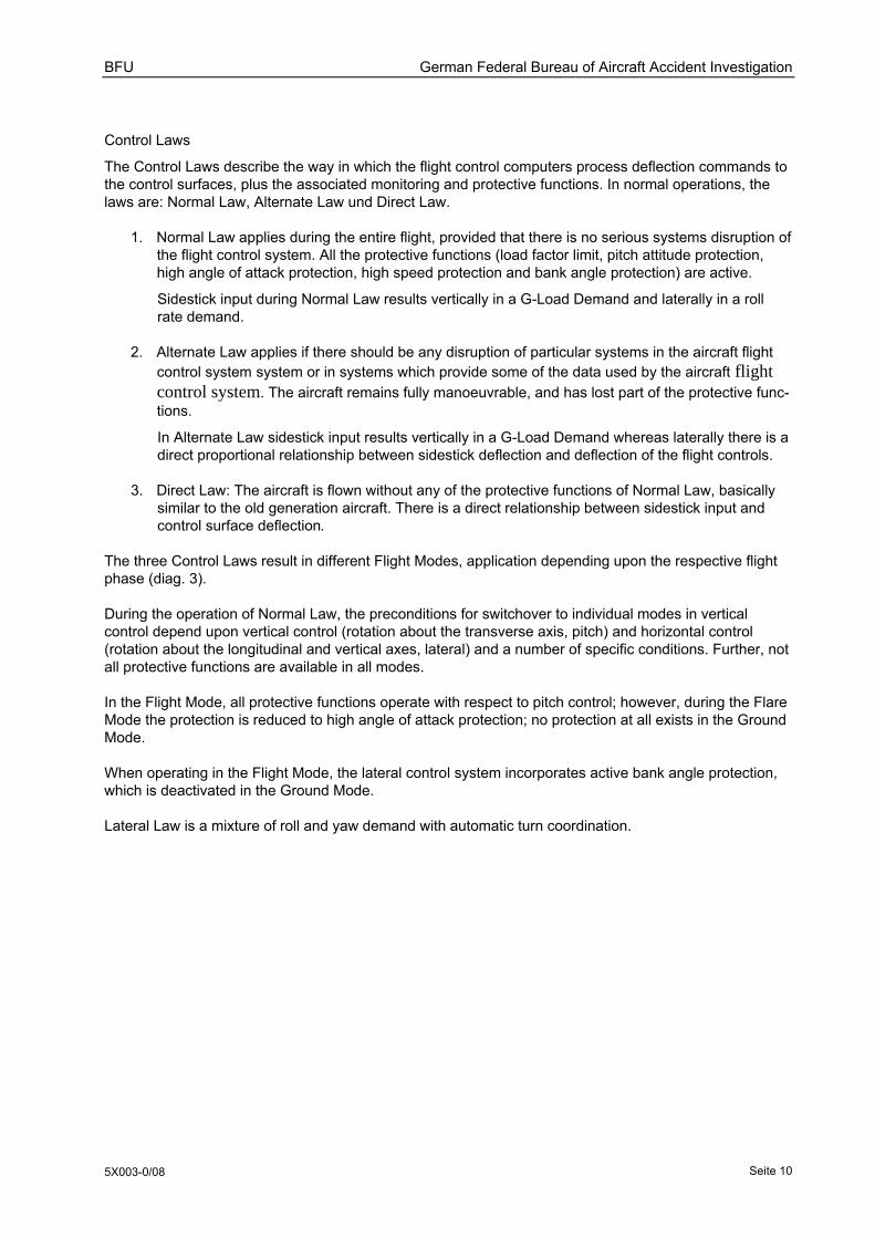
At 1333:40 hrs the anemometer near the threshold of Runway 23/33 registered the surface wind as 299°/32 kt (here: 2-minute mean value). No change was registered in the wind at 1334:00 hrs (wind direction 299°).
In the final ten minutes prior to the occurrence the wind direction varied between 268° (minimum) and 323° (maximum). In this period, the maximum gust speed recorded was 47 kt.
Diag. 4: Surface wind in the last 10 minutes prior to touch down. Source: BFU, drawing AIP
Winds Aloft and Turbulence
The AMDAR (Aircraft Meteorological Data Report) sensor records for 1515 hrs (Bremen) and 1538 hrs (Hamburg) can be regarded as representative for the winds aloft at the time of the incident. From this it can be demonstrated that the wind at about 500 m AMSL was 290° to 300° at speeds of 23 m/s (approx. 46 kt) to 24 m/s (approx. 48 kt).
Provision of wind data for Air Traffic Control Service
At Hamburg Airport the wind data logged by the DWD anemometer near the threshold of Runways 23/33 and 15 is passed via a fixed modem installation within the airport to the Air Traffic Control service provider. The aerodrome weather data required for the Approach and Aerodrome controllers are updated
BFU German Federal Bureau of Aircraft Accident Investigation
5X003-0/08 Seite 14
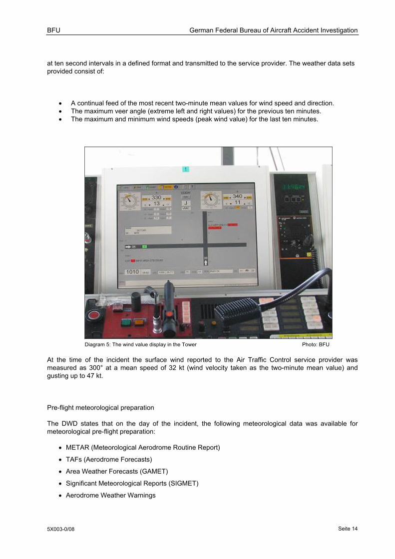
at ten second intervals in a defined format and transmitted to the service provider. The weather data sets provided consist of:
• A continual feed of the most recent two-minute mean values for wind speed and direction. • The maximum veer angle (extreme left and right values) for the previous ten minutes. • The maximum and minimum wind speeds (peak wind value) for the last ten minutes.
Diagram 5: The wind value display in the Tower Photo: BFU
At the time of the incident the surface wind reported to the Air Traffic Control service provider was measured as 300° at a mean speed of 32 kt (wind velocity taken as the two-minute mean value) and gusting up to 47 kt.
Pre-flight meteorological preparation
The DWD states that on the day of the incident, the following meteorological data was available for meteorological pre-flight preparation:
• METAR (Meteorological Aerodrome Routine Report)
• TAFs (Aerodrome Forecasts)
• Area Weather Forecasts (GAMET)
• Significant Meteorological Reports (SIGMET)
• Aerodrome Weather Warnings

BFU German Federal Bureau of Aircraft Accident Investigation
5X003-0/08 Seite 15
During the flight, the current weather was provided by the Aircraft Communications Addressing and Reporting System (ACARS) and made available in the cockpit in the form of METARs, Aerodrome Weather Warnings and SIGMETs.
Aerodrome Forecasts
The Aerodrome Forecasts valid for the period 1100 hrs (1000 UTC) to 2000 hrs (1900 UTC) (issued at 1000 hrs (0900 UTC)) forecast the surface wind as 280° at an average speed of 25 kt, gusting up to 45 kt.
For the period 1200 hrs to 1800 hrs the forecast was for the surface wind to temporarily (TEMPO) become 290° with a mean wind speed of 30 kt and gusting up to 55 kt.
TAF EDDH 010900Z 011019 28025G45KT 9999 SCT015 BKN025 TEMPO 1019 3000 SHRAGS BKN008CB TEMPO 1117 29030G55KT=
Area Weather Forecasts (GAMET)
GAMET Area Weather Forecasts are for flights at lower levels. The forecast describes the specific meteorological dangers or hazards en route, together with the times and places at which these may be encountered. A GAMET forecast further describes the current weather situation and likely development within a (FIR) Flight Information Region. The format requirements, guidelines and recommendations for a GAMET Area Weather Forecast are set out in ICAO Annex 3. A GAMET forecast consists of two sections:
• The first Section 1 (SECN 1) contains information for flights at low levels and describes potentially dangerous en route weather conditions; further, this information is also used for the preparation of AIRMET warnings for flights at lower levels.
• Section 2 (SECN 2) contains supplementary weather information that may be relevant for flights at lower levels. This would include such information as the location of the centre of a depression, fronts and their anticipated movement, and pressure system (PYS) development.
The GAMET for FIR Bremen, in effect between 1000 hrs (0900 UTC) and 1600 hrs (15:00 UTC) forecast moderate to strong turbulence below FL50 and moderate ice above1,500-2,00 ft; isolated CB and one trough.

BFU German Federal Bureau of Aircraft Accident Investigation
5X003-0/08 Seite 16
Diag. 6: Area Weather Forecast for the Bremen FIR Source: DWD

BFU German Federal Bureau of Aircraft Accident Investigation
5X003-0/08 Seite 17
Weather Warnings
The DWD aviation weather forecast service issues different types of warnings. These are so-called AIRMET and SIGMET warnings, and Aerodrome Weather Warnings.
AIRMET Warnings
AIRMETs are issued to aviators to give warning of weather conditions that pose a potential threat to the safety of a flight (AIRMET Information), and are issued by the Meteorological Watch Office (MWO) in the respective FIRs. They contain a brief description of the actual or predicted presence of a specific en route threat within the FIR, together with its location and likely change with time.
AIRMET warnings are issued in accordance with guidelines and recommendations published in ICAO Annex 3, and in the ICAO Air Navigation Plan for Europe (EUR ANP). AIRMET warnings are issued for lower airspace (up to FL100 and FL150), if specific weather conditions occur or are forecast but are not mentioned within Section 1 of the current valid GAMET Area Weather Forecast. The criteria (e.g. moderate turbulence) for the issue of an AIRMET report are set down in ICAO Annex 3, Appendix 5.
An AIRMET was not issued for the period relating to the flight in question.
SIGMET Warnings
SIGMET reports are Significant Meteorological Information weather warnings for pilots and contain information on conditions that could pose a threat to the safety of the flight. They are issued by the Meteorological Watch Office in the respective FIRUIR or control area in the FIR/UIR. They contain a brief description of the actual or predicted presence of a specific en route threat within the FIR, together with its location and likely change with time.
SIGMET warnings are issued in accordance with guidelines and recommendations published in ICAO Annex 3, and in the ICAO Air Navigation Plan for Europe (EUR ANP). Are certain criteria met, e.g. severe turbulence (observed or expected), a SIGMET warning must be issued in accordance with ICAO Annex 3.
A further SIGMET warning (SIGMET 04) was issued for the Bremen FIR at 0947 hrs, valid for the period 1000 hrs to 1400 hrs.
EDWW BREMEN FIR SEV TURB FCST BLW FL050, STNR, NC =
At about 1330 hrs the existing warning was extended to 1800 hrs by issue of a new SIGMET warning.
Aerodrome Weather Warnings
The DWD aviation weather briefing stations issue Aerodrome Weather Warnings for international and regional airports within their particular area of responsibility. The warnings alert the respective aerodrome of weather threats to aircraft parked or standing outside, and threats to airport installations. The warnings should be passed to the Tower, aeronautical meteorological offices, the airport operating company, providers of aerodrome services and air operators. Warnings are issued in accordance with guidelines and recommendations published in ICAO Annex 3, and in the ICAO Air Navigation Plan for Europe (EUR ANP).
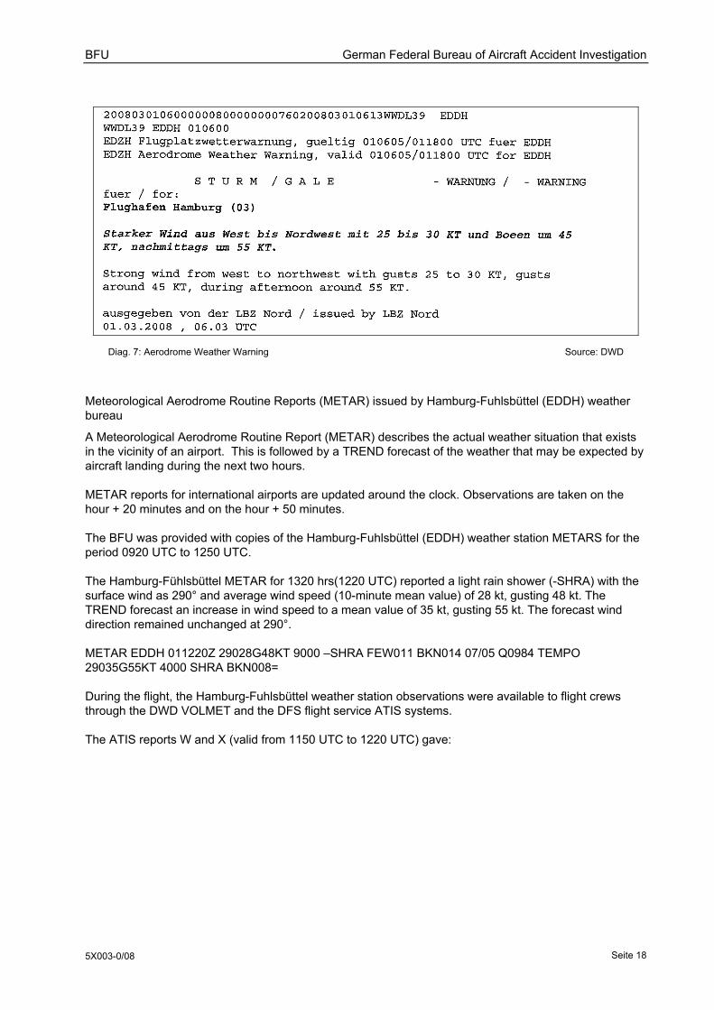
On 1 March 2008 the North German aviation weather briefing service in Hamburg issued an Aerodrome Weather Warning for international airports in Hannover (EDDV), Bremen (EDDW) and Hamburg (EDDH). The warning was valid for the period 0705 hrs (0605 UTC) to 1900 hrs and stated:
BFU German Federal Bureau of Aircraft Accident Investigation
5X003-0/08 Seite 18
Diag. 7: Aerodrome Weather Warning Source: DWD
Meteorological Aerodrome Routine Reports (METAR) issued by Hamburg-Fuhlsbüttel (EDDH) weather bureau
A Meteorological Aerodrome Routine Report (METAR) describes the actual weather situation that exists in the vicinity of an airport. This is followed by a TREND forecast of the weather that may be expected by aircraft landing during the next two hours.
METAR reports for international airports are updated around the clock. Observations are taken on the hour + 20 minutes and on the hour + 50 minutes.
The BFU was provided with copies of the Hamburg-Fuhlsbüttel (EDDH) weather station METARS for the period 0920 UTC to 1250 UTC.
The Hamburg-Fühlsbüttel METAR for 1320 hrs(1220 UTC) reported a light rain shower (-SHRA) with the surface wind as 290° and average wind speed (10-minute mean value) of 28 kt, gusting 48 kt. The TREND forecast an increase in wind speed to a mean value of 35 kt, gusting 55 kt. The forecast wind direction remained unchanged at 290°.
METAR EDDH 011220Z 29028G48KT 9000 –SHRA FEW011 BKN014 07/05 Q0984 TEMPO 29035G55KT 4000 SHRA BKN008=
During the flight, the Hamburg-Fuhlsbüttel weather station observations were available to flight crews through the DWD VOLMET and the DFS flight service ATIS systems.
The ATIS reports W and X (valid from 1150 UTC to 1220 UTC) gave:

BFU German Federal Bureau of Aircraft Accident Investigation
5X003-0/08 Seite 19
Diag. 8: ATIS W Source: DFS
Diag. 9: ATIS Y Source: DFS
Diag. 10: ATIS Z Source: DFS
Supplementary Clarification by the DWD
The BFU investigation team put a number of questions to the DWD seeking clarification on the meteoro-logical aspects of the flight, to which the team received answers and further background information.
Gust Generation
Wind at lower levels is slower as a result of friction with the Earth's surface. Frictional forces also modify the wind speed and direction. Gusts arise from turbulent mixing of air in the boundary layer; for the sake

BFU German Federal Bureau of Aircraft Accident Investigation
5X003-0/08 Seite 20
of simplicity, gusts can be regarded as air packets forced down from higher altitude winds that have their own direction and speed. As a first approximation, one can generalise by defining a gust as being about 1.5 times faster than the mean surface wind. Given a generally smooth land surface area, when the wind blows strong and the weather is stormy, the most powerful gusts blow in the same direction as the wind above the boundary layer. In the northern hemisphere the wind veers clockwise about 10° to 20° with respect to the mean wind direction. These assumptions do not hold good in hilly terrain, thunderstorms, thermal weather conditions, during the passage of fronts and so forth.
The following explanation was published in AIP GEN 3.5 Attachment3:
Variations from the mean wind speed (gusts) are preceded by „G“ and are reported as under 1.1.1.2. Gusts will be reported if during the average time interval the maximum wind speed (peak gust) exceeds the mean wind speed by at least 10 kt. To determine the peak gust, the 3-second average of the wind speed is used. For gusts no direction is given. [ …]
The incidence of weather patterns at Hamburg Airport associated with high wind speeds.
The DWD provided this table summarising the number of days per month in which the gusts reached or exceed 41 kt (Storm according to Beaufort scale):
Year Total Jan. Feb. Mar. Apr. May June July Aug. Sep. Oct. Nov. Dec. 1993 15 9 1 1 1 3 1994 13 3 1 6 1 1 1 1995 12 5 2 3 1 1 1996 3 2 1 1997 5 3 1 1 1998 7 1 1 3 2 1999 7 2 1 4 2000 10 4 2 1 1 1 1 2001 2 1 1 2002 11 2 5 1 1 2 2003 4 2 1 1 2004 5 1 1 2 1 2005 6 2 1 1 2 2006 2 2 2007 9 6 1 1 1 2008 8 2 2 3 1
Diag. 11: Number of days per month in which gusts reached or exceed 41 kt Source: DWD
ICAO Annex r regarding AIRMET and GAMET
Annex 3 defines AIRMET as follows:
„Information issued by a meteorological watch office concerning the occurrence or expected occurrence of specified en-route weather phenomena which may affect the safety of low-level aircraft operations and

BFU German Federal Bureau of Aircraft Accident Investigation
5X003-0/08 Seite 21
which was not already included in the forecast issued for low-level flights in the flight information region concerned or sub-area thereof.”
Chapter 7 SIGMET and AIRMET information, aerodrome warnings and wind shear warnings determines the issue of AIRMET as follows:
„ …AIRMET information shall give a concise description in abbreviated plain language concerning the occurrence and/or expected occurrence of specified en-route weather phenomena, which have not been included in Section I of the area forecast for low-level flights issued in accordance with Chapter 6, Section 6.6 and which may affect the safety of low-level flights, and of the development of those phenomena in time and space.”
Chapter 6 Forecasts determines under point 6.6 Areaforcast for low level flights, that GAMET forecast “… in support of the issuance of AIRMET information…” i.e. should serve as supplements to AIRMET information.
Annex 3, Chapter 9 lists weather report information which should be made available to pilots and aircraft operators, this list includes AIRMET information also.
1.8 Aids to Navigation
An Instrument Landing System (ILS) CAT-II/ III was available for approaches to Runway 23. LOC/DME and RNAV (GPS) approaches were published for Runway 33.
1.9 Communications
The aircraft was in radio contact with Bremen Radar and airport Air Traffic Control tower. The inter-change was recorded and available to the BFU for this investigation.
1.10 Aerodrome Information
Hamburg Airport is about 8.5 km north of the city centre and is located within a control zone (CTR) extending to 2,500 ft MSL. The airport has a first runway 3,250 m long and 45.8 m wide oriented 050°/230°, and a second runway 3, 666 m long and 45.8 m wide oriented 153°/333°. Both runways have an asphalt surface.
The published Landing Distance Available (LDA) for runway 23 is 3,094 m, while that for runway 33 is 3,220 m.
1.11 Flight Recorders
Cockpit Voice Recorder
The aircraft was equipped with a Cockpit Voice Recorder (CVR) FA 2100 made by L3Com.
The CVR has a recording endurance of 30 minutes on each of four discrete channels, and of two hours for joint channel operation. Those parts of the conversation relevant to this investigation formed part of a two-hour recording, i.e. the words spoken by the captain and co-Pilot were co-located on a single channel.
The CVR was passed to the BFU flight data recording laboratory for evaluation and the words spoken were transcribed.
BFU German Federal Bureau of Aircraft Accident Investigation
5X003-0/08 Seite 22
Digital Flight Data Recorder
The aircraft was fitted with a Digital Flight Data Recorder (DFDR) type F1000 manufactured by Fairchild. The DFDR records a total of 327 parameters for a period of 25 hours.
The DFDR was passed to the BFU flight data recording laboratory for evaluation. The parameters relevant to this investigation are presented as graphs in Appendix 3.
The DFDR record shows that at a height of 75 ft above ground the aircraft drifted left. The co-pilot responded with a sidestick command of 10° correction to the right.
At 50 ft above ground the co-pilot moved the sidestick left. During the subsequent five seconds, the rudder pedals were deflected left up to 28°.
At 15 ft above ground the captain moved the sidestick 4.5° right. The co-pilot's input changed from left to right. The left main landing gear then touched at 1333:33 hrs the runway briefly with the wings in a 4° left bank.
During the ensuing bounce, the roll angle increased to 23° left wing down. Both, the captain and co-pilot gave full right sidestick deflection and 14° right rudder. The right aileron shifted to 6° upwards deflection and the left aileron gave 15° downwards deflection. The right roll spoiler extended by 8°.
The left main gear touched down a second time at 1333:35 hrs at a speed of 144 kt with the left wing down 23° and wing angle of attack of 1.5°. The Co-pilot selected maximum thrust (TOGA) and initiated the go-around procedure. The Captain assumed control and at 1333:38 hrs pressed the Take Over Button on the left sidestick.
1.12 Wreckage and impact information
The aircraft left wingtip touched the runway tarmac about 450 m from the threshold of Runway 23.
Contact with the runway resulted in damage to the wing tip fence, slat No. 5 and leading edge slat rail guides 11 and 12. These components were replaced before the aircraft was returned to service.
During the repair, a further inspection was made of the airframe, the control surfaces and the main landing gear. The inspection revealed no further damage that could be ascribed to the landing incident.

BFU German Federal Bureau of Aircraft Accident Investigation
5X003-0/08 Seite 23
Diag. 12: Damage in the vicinity of the left wingtip (Source: BFU)
1.13 Medical and pathological information
Not applicable
1.14 Fire
There was no fire.
1.15 Survival aspects
Not applicable.
1.16 Tests and research
The aircraft manufacturer conducted tests on an 'Iron Bird' simulator used in the development of aircraft and their systems. The nature of the tests and the results are described under heading 1.19.
1.17 Organisational and management information
1.17.1 Air operator company
The aircraft was in use by an Operator in accordance with Regulation (EC) No 1008/2008. At the time of the incident, the Air Operator Certificate recorded the operator has having a total of 248 aircraft, of which 83 were Airbus A319/A320/A321.
Damage

BFU German Federal Bureau of Aircraft Accident Investigation
5X003-0/08 Seite 24
1.17.2 Air Traffic Control
The Air Traffic Control service provider company for Germany is responsible for the safe conduct of flights to and from 16 international airports and has a subsidiary company with similar responsibilities for nine regional airports.
The company was responsible for the provision of en route air traffic control services for the flight from Munich to Hamburg, and for the approach to Hamburg Airport.
The division of responsibilities and the air traffic control procedures were defined in Manual of Operations ATC (BA-FVK) and the Operating Procedures (BAO).
1.17.3 German Meteorological Service
The German Meteorological Service (DWD) is the national meteorological service for the Federal Republic of Germany and is the service provider for weather reports and climatic information. Its services include the provision of maritime and aeronautical weather information, including precautionary warnings of conditions that could represent a danger to public safety.
The DWD bears the legal responsibility for the provision of aeronautical meteorological services.
From the organisational standpoint, aviation weather services come under the Forecast Section within the DWD Flight Meteorology Department. The Meterological Briefing Center (LBZ) are also subordinate to the Flight Meteorology Department.
Aviation weather briefing and documentation services
The Aeronautical Information Publication (AIP Germany GEN 3.5) states that the provision of Aeronauti-cal Meteorological Office briefing services is the responsibility of the Advisory Centre for Aviation). At the time of the incident, the provision of information and documents was the immediate responsibility of the Aeronautical Meteorological Offices at seven international airports. The briefing was provided as agreed locally either verbally or in written form,
Weather briefing documents were handed out in the meteorological briefing room and consisted of
• Aerodrome Forecasts (TAFs) for the airports of departure, destination and alternates.
• The en route forecast (significant weather, winds aloft and temperatures, tropopause altitudes, maximum wind speeds)
• Other documents as requested
For short-distance flights the DWD service included, on request, the provision of a weather overview or summary in simplified tabular form.
Aviation weather data service
The DWD Aeronautical Meteorological Service Operations Handbook states that the Aviation Weather Data Service is designed to meet the requirements of ICAO Annex 3, i.e. the provision of aviation meteorological data and documents for pilots and air traffic control services.
Aviation Weather Data Service Products:
• Documentation folder • INFOMET service • Weather information by Telefax on demand • Recorded weather briefing by telephone (for VFR flights)
Documentation folders are produced in accordance with ICAO Annex 3, Chapter 9 and contain printed meteorological briefing papers to aid pilots and air operators in the preparation and safe conduct of their

BFU German Federal Bureau of Aircraft Accident Investigation
5X003-0/08 Seite 25
flights. Documentation folders are handed over by the Aeronautical Meteorological Office directly to the aviation customer or his delegated representative. Alternatively, the documentation folder maps are copied and placed ready for collection by the customer.
Documentation folder
The documentation folder contents are designed to meet the requirements of ICAO Annex 3, Chapter 9 and consist of:
• The forecast winds aloft and the temperatures with respect to standard pressure at specified Flight Levels
• Significant Weather Chart (SWC), including information on the tropopause and maximum wind speed
• SIGMETs for the entire route • If available, warning of tropical cyclones and volcanic ash for the entire flight • If available, forecast charts for the movement of volcanic ash for the entire flight • TAFs for the airports of departure, arrival and alternates • METARs (with TREND) for the airports of departure, arrival and alternates • AIRMETs for low-level flights
INFOMET – weather briefing
The weather briefing service defined in ICAO Annex 3, Chapter 9, 9.3 implies a detailed discussion or clarification of the information contained in the documentation folder, but the DWD Aeronautical Meteorological Service Operations Handbook stated hat in practice Aeronautical Meteorological Offices no longer provide any such service. Personal briefings have been replaced by the INFOMET service, which provides the information necessary for the planning and safe conduct of flights of all types (VFR flights, IFR flights, gliders, balloons etc.). The INFOMET service is generally provided from the Aeronauti-cal Meteorological Office by telephone, with the objective of relieving the Meteorological Briefing Centres (LBZ) of the burden of dealing with simple enquiries.
The INFOMET service is a telephone information service provided by the DWD, providing updated weather reports, meteorological flight forecasts and reports, plus aviation weather warnings.
The following types of information may be provided by the INFOMET service: • METAR/SPECI • TAF • SYNOP • GAFOR • AIRMET • SIGMET • GAMET • AIR-REPORT/SPECIAL AIR-REPORT • PIREP • Aerodrome Weather Warnings • General overview of aviation-relevant weather conditions • Weather reports for glider pilots • Weather reports for balloon pilots • Three-day forecast • Description of weather radar images • Description of weather satellite images • Description of graphic products
BFU German Federal Bureau of Aircraft Accident Investigation
5X003-0/08 Seite 26
Fax Call-Up Service
This service acts as a backup for possible failure of the central fax server, and to meet the requirements of customers with special requirements. The local fax call-up service is classified as one of the self-briefing methods provided by the DWD.
The Fax Call-Up service embraces the IFR standard program:
• Short TAFs for Central Europe, all the available German and Swiss TAFs, plus other TAFs re-quested by the customer.
• Significant Weather Chart (WAFC London) FL100-450 • Wind/Temperature Chart FL100/180/240/300/340/390 EUR • GAMETs provided by the five German Meteorological Watch Offices (MWO)
Supply of weather data to air operators
The DWD Aviation Meteorological Service Operations Handbook notes that the Air Operator in this incident received a data feed from the DWD main bureau in Offenbach via two data links. "all the aviation meteorological observations, warnings and weather forecast products necessary for flight planning and the safe conduct of the flight" were accessible via the computer network.
The air operator's subsidiaries were equipped with the pc_met internet weather briefing system. The meteorological forecast charts and TAF lists were available to the Air Operator by call-up through the fax server.
At local level, the provision of weather briefing was arranged between the respective Advisory Centre for Aviation main office and the station manager. A local agreement regulated the extent and content of this provision, and the local transmission times were adjusted as necessary.
The supply of weather data to other air operators and handling services
It was laid down that, in general, Air Operators or their contracted handling agents would obtain the weather briefing required for the safe conduct of the flight from the Aeronautical Meteorological Office. However, there has also been a steady increase in the use of DWD self-briefing systems.
1.18 Additional Information
1.18.1 Flight Manuals
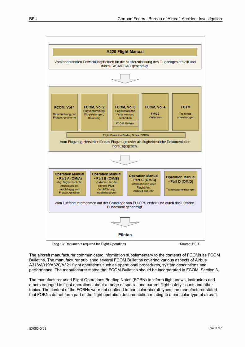
During the development of a new aircraft the manufacturer writes a Flight Manual (FM) that becomes part of the formal type certification process and is subsequently agreed by the Certification Authority. This Flight Manual serves the manufacturer as the basis for the Flight Crew Operating Manual (FCOM), which describes and defines the correct operation of the aircraft for the air operator and flight crews.
The Air Operator in this incident adopted the contents of the FCOMs into the Operating Manual (OM/A – OM/D) required under the EU-OPS regulations; to meet specific operating requirements, the company made a number of changes and additions to the OM, which was approved by the Civil Aviation Authority (Luftfahrt-Bundesamt).
BFU German Federal Bureau of Aircraft Accident Investigation
5X003-0/08 Seite 27
Diag.13: Documents required for Flight Operations Source: BFU
The aircraft manufacturer communicated information supplementary to the contents of FCOMs as FCOM Bulletins. The manufacturer published several FCOM Bulletins covering various aspects of Airbus A318/A319/A320/A321 flight operations such as operational procedures, system descriptions and performance. The manufacturer stated that FCOM-Bulletins should be incorporated in FCOM, Section 3.
The manufacturer used Flight Operations Briefing Notes (FOBN) to inform flight crews, instructors and others engaged in flight operations about a range of special and current flight safety issues and other topics. The content of the FOBNs were not confined to particular aircraft types; the manufacturer stated that FOBNs do not form part of the flight operation documentation relating to a particular type of aircraft.

BFU German Federal Bureau of Aircraft Accident Investigation
5X003-0/08 Seite 28
1.18.2 Operational instructions for the flight crew
1.18.2.1 Operations Manual Part A (OM/A)
The Captain’s tasks and responsibilities
The Captain's tasks and responsibilities were defined in Chapter 1.12 of the Air Operator's Operations Manual OM/A. The manual describes the requirements of the Multi Crew Concept (MCC) with respect to the division of work between the PF/PNF as follows:
[…]
"He organizes the work of the flight deck team in accordance with the principles according to OM/A 8.3.3 Multi Crew Concept (MCC) and determines who performs the duties of PF and PNF.
He sets priorities and makes his decisions giving priority to safety and consideration to economy, passenger comfort and punctuality.
As far as the flight operation allows, the commander shall contribute to expanding the experience and knowledge of the flight crew. That includes giving the co-pilot, under his supervision, the opportunity to independently plan and execute route-legs.
Whenever the commander, considering all relevant factors and circumstances, deems a take-off, approach or landing critical, he shall perform this portion of the flight as PF. Furthermore, whenever it appears to be called for in the interest of safety, he shall personally take over the control of the aeroplane, respectively give timely corrective comments and, if needed, take corrective action in the case of deviations from orderly flight execution.
The commander shall check that flight crew members are properly qualified prior to commencing a low visibility take-off in an RVR of less than 150 m (category A, B and C aeroplanes) or 200 m (category D aeroplanes) or a CAT II/III approach. Principally this qualification is assured by the procedures of training and licensing and the scheduling department."
[…]
The Operations Manual did not specify which crew member should exercise the function of PF (pilot flying) and PNF (pilot non flying), except in conditions of reduced visibility and in the course of critical take-offs and landings.
In regular medium-range operations, the practice was for the Captain to exercise the role of PF during the first sector, following which the roles would be reversed at each new sector. There were deviations from this practice during particular training phases or for departures from the home base airport. When departing from the home base, the allocation of roles was decided to maximise pilot experience of landing at as many airports as possible.
Crew Resource Management
The required use of resources and Cockpit teamwork was defined in OM/A Chapters 8.3.2 and 8.3.3 as follows:
8.3.2 Crew Resource Management (CRM) CRM is defined as the utilisation of all available human, informational and equipment resources towards the effective performance of a safe and efficient flight.

BFU German Federal Bureau of Aircraft Accident Investigation
5X003-0/08 Seite 29
CRM is an active process by crew members to identify significant threats to an operation, communicate them to each other and to develop and take measures to avoid or minimize the risk. CRM skills provide a primary line of defence against threats to safety that exist in the aviation system and against human errors and its consequences. The basic performance of flight crew (OM/A 8.3.1 Flight Procedures) has been defined, so as to include all CRM skills required by EU-OPS and JAR-FCL. 8.3.3 Multi Crew Concept (MCC) The Multi Crew Concept (MCC) regulates the organization of work and task sharing on the flight deck. The objectives are as follows: • full availability of the PF for the primary task of flying the aeroplane • clearly defined and balanced workload distribution • mutual information, supervision and support to achieve a maximum of redundancy.
The operator supplemented the CRM- and MCC-regulations set down in OM/A with a brochure in which the cockpit teamwork defined three skills:
• Technical Competence • Procedural Competence • Interpersonal Competence
Interpersonal Competence describes optimum teamwork in the cockpit including the use of all resources, as embraced by the CRM philosophy
and calls for
• Communication • Leadership and Teamwork • Workload Management • Situational Awareness and Decision Making
Choice of the most suitable runway
Section 8.3.4.5 of OM/A contains the following guidance on the factors to be considered when choosing the runway for a landing:
"For take-off and landing the runway which gives the optimum safety margin under prevailing conditions should be used, regarding all relevant factors (e.g. contamination, approach and landing aids, local conditions, preferential runway as described in OM/C)".
1.18.2.2 Operations Manual Part B (OM/B)
Crosswind landing techniques
Chapter 2 of the operator's OM/B has the following headings above its observations on crosswind landing techniques
2. Normal Procedures, 2.3 Procedures & Techniques 2.3.30 Background Information on A320 Family Operation
Landing
[…]

BFU German Federal Bureau of Aircraft Accident Investigation
5X003-0/08 Seite 30
"Crosswind Landings are conventional. The preferred technique is to use the rudder to align the aircraft with the runway heading, during the flare, while using lateral control to maintain the aircraft on the runway centreline. The lateral control mode does not change until the wheels are on the ground, so there is no discontinuity in the control laws. The aircraft tends to roll gently in the conventional sense as drift decreases, and the pilot may have to use some normal cross control to maintain roll attitude. In strong crosswind conditions, small amounts of lateral control may be used to maintain the wings level. This lateral stick input must be reduced to zero at first main landing gear touchdown. Even during an approach in considerable turbulence, the control system resists the disturbances quite well without pilot inputs. In fact, the pilot should try to limit his control inputs to those necessary to correct the flight path trajectory and leave the task of countering air disturbances to the flight control system."
[…] Aircraft Handling in the Roll-Axis
[…] "Use of rudder, combined with roll inputs, should be avoided, since this may significantly increase the pilot´s lateral handling tasks. Rudder use should be limited to the "de crab" manoeuvre in case of crosswind, while maintaining the wings level, with the sidestick in the roll axis." 1.18.2.3 Operations Manual Part C (OM/C)
No limitations were published with respect to the choice of landing runway in Hamburg.
1.18.2.4 Operations Manual Part D (OM/D)
The operator's Training Syllabus was set out in OM/D, and described three different crosswind landing techniques:
• "Wing-Low"-Method
• "Crab-Angle"-Method
• Combination of the two methods given above
Our limit is 30 kt on both wet and dry runways. The maximum CWC crosswind component demonstrated by Airbus is 33 kt gusting 38 kt (All values for hand-flown landings). The limits are due to reduced braking action (Wet, Contaminated – s. QRH) or "One Reverser Inop".
The easiest and safest way to land our "Fly by wire" is by using a combination of the wing-low and crab-angle methods.
How is the aircraft de-crabbed?
The aircraft nose is aligned parallel with the runway centreline by a steady and relatively slow rudder input. Initially, the pilot applies slight pressure to the rudder pedal until the aircraft responds; the pressure is increased as necessary to bring the fuselage longitudinal axis into parallel alignment with the runway centreline. When the correct presentation has been achieved, the pilot holds the rudder bar in this position: the pilot has found the appropriate neutral rudder pedal position for this crosswind landing. Having found this offset position, he makes small corrections as necessary.
At the same time, the pilot makes a small into-wind aileron correction, in order that the into-wind main landing gear touches first. This control input is usually instinctive, but it must be remembered that sidestick deflection regulates the roll rate.
BFU German Federal Bureau of Aircraft Accident Investigation
5X003-0/08 Seite 31
It should be anticipated that after touchdown rudder deflection must initially increase with decreasing speed; but reduces when the nose gear makes contact with the runway and provides steering force. Under 130 kt both the rudder and nose gear steering are in operation.
When does de-crabbing begin?
That depends: in general it is not a good idea to touch down on a dry runway with a distinctive crab angle. On touchdown the aircraft would make a sudden correctional yaw motion to realign the wheels with the direction of travel. This greatly increases the loads on the tyres and airframe, and is unpleasant for passengers. The pilot can reduce a small residual crab angle (up to 50%) to zero as the nose gear lowers onto the runway. The decrab procedure begins at about 50 ft when the pilot initiates pressure on the rudder pedal, followed by correction to the stable neutral point during the flare with the nose parallel to the runway centreline. A simultaneous into-wind wing-down sidestick correction reduces the risk that this wing will suddenly lift (in other words, a deliberate crossed-control correction). It is not necessary for the aircraft to be 100 per cent decrabbed when the main gears touch down; reducing a large crab angle slowly to zero takes some time. Should there be a residual crab angle when the nose gear touches down, the steering correction can be made at once. If the aircraft still has a crab angle in the flare, under no circumstances should the pilot attempt to hold off either the main or nose gear in order to gain time to de-crab the aircraft in the air. It is better to land with the residual crab angle.
Frequent Mistakes: • Attempting to de-crab too soon • De-crabbing action too sudden and too early, causing swing in the roll and yaw axes. • Cancellation of rudder input on the ground • Aircraft flares too high
1.18.3 Operational Instructions contained in the aircraft manufacturer's documentation
1.18.3.1 Flight Crew Operating Manual
For the guidance of Air Operators and flight crew and based on the Flight Manual (FM), the Airbus A320 manufacturer published the Flight Crew Operating Manual (FCOM) Volumes 1 to 4 and the Flight Crew Training Manual (FCTM),
The crosswind landing technique was described in FCOM A319/A320/A321, Volume 3, Chapter 3.04.27, under Supplementary Techniques.
"Crosswind Landings are conventional. The preferred technique is to use the rudder to align the aircraft with the runway heading, during the flare, while using lateral control to maintain the aircraft on the runway centreline (Refer to SOP 3.03.22). The lateral control mode does not change until the wheels are on the ground, so there is no discontinuity in the control laws. The aircraft tends to roll gently in the conventional sense as drift decreases, and the pilot may have to use some normal cross control to maintain roll attitude. Even during an approach in considerable turbulence, the control system resists the disturbances quite well without pilot inputs. In fact, the pilot should try to limit his control inputs to those necessary to correct the flight path trajectory and leave the task of countering air disturbances to the flight control system."
[…]
1.18.3.2 Airbus A318/A319/A320/A321 Flight Crew Training Manual (FCTM)
In the issue dated March 09/07, section 02.160 gave the following description of landing techniques for training purposes:
BFU German Federal Bureau of Aircraft Accident Investigation
5X003-0/08 Seite 32
FINAL APPROACH
• In crosswind conditions, a crabbed-approach should be flown.
FLARE
The objectives of the lateral and directional control of the aircraft during the flare are:
• To land on the centerline
• and to minimize the loads on the main landing gear.
During the flare, rudder should be applied as required to align the aircraft with the runway heading. Any tendency to drift downwind should be counteracted by an appropriate input on the sidestick.
In the case of a very strong cross wind, the aircraft may be landed with a residual drift (maximum 5°) to prevent an excessive bank (maximum 5°).
Consequently, a combination of the partial de-crab and wing down techniques may be required.
1.18.3.3 Airbus A318/A319/A320/A321 FCOM-Bulletin No. 828/1
In June 2004 the aircraft manufacturer issued FCOM-Bulletin No. 828/1 as a supplement to FCOM, giving further guidance on yaw control and use of the rudder.
The Bulletin made the following operational recommendations:
"In order to avoid exceeding structural loads on the rudder and vertical stabilizer, the following rec-ommendations must be observed.
1. The rudder is designed to control the aircraft in the following circumstances:
1.1 In normal operations, for lateral control:
• During the takeoff roll, when on ground, especially in crosswind conditions.
• During landing flare with crosswind, for decrab purposes.
• During the landing roll, when on ground.
In these circumstances, large and even rapid rudder inputs may be necessary to maintain control of the aircraft.
Rudder corrections should always be applied as necessary to obtain the appropriate aircraft re-sponse".
This FCOM-Bulletin 828/1 was listed in the Air Operator's OM/B, Chapter 2.3.40 and incorporated with no changes in full.
1.18.3.4 Airbus A318/A319/A320/A321 FCOM-Bulletin No. 827/1
The FCOM Bulletin issued in June 2004 provided operational advice for a stable approach, including the following recommendations:
Before flare height, heading corrections should only made with roll. As small bank angles are possible and acceptable close to the ground, only small heading changes can be envisaged. Otherwise, a go-around should be initiated.
BFU German Federal Bureau of Aircraft Accident Investigation
5X003-0/08 Seite 33
Use of rudder, combined with roll inputs, should be avoided, since this may significantly increase the pilot’s lateral handling tasks. Rudder use should be limited to the "de-crab" manoeuvre in case of crosswind, while maintaining the wings level, with the sidestick in the roll axis. (Refer to the FCOM’s SOP, for Crosswind Landing Techniques).
Note:
FCOM Bulletin 827/2 was prepared, but had not yet been issued by the aircraft manufacturer.
The second section (Use of rudder …..) was incorporated as a supplementary description for crosswind landings in OM/B (section 2.2.30).
1.18.3.5 Flight Operations Briefing Note (FOBN) "Landing Techniques Crosswind Landings"
The FOBN published by the aircraft manufacturer in April 2006 described crosswind landing techniques and provided further background information on the subject.
The crosswind landing technique descriptions were sub-divided into two phases:
• Final Approach and
• Flare.
The technique to be adopted in the Final Approach phase was described as follows:
"Figure 1 shows that depending on the recommendations published in the aircraft-operating man-ual, the final approach under crosswind conditions may be conducted:
With wings-level (i.e., applying a drift correction in order to track the runway centerline, this type of approach is called a crabbed approach [Airbus recommended technique]), or
With a steady sideslip (i.e., with the aircraft fuselage aligned with the runway centerline,
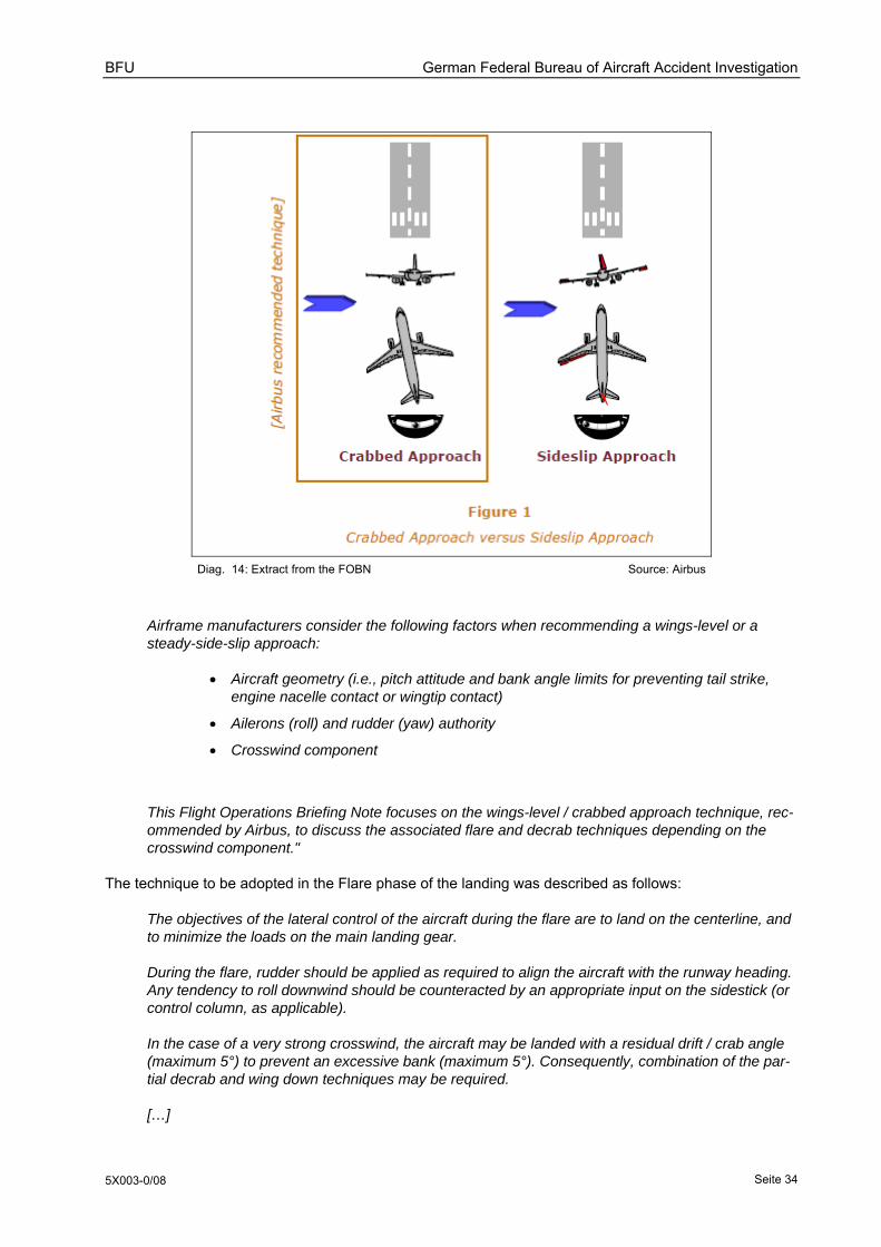
BFU German Federal Bureau of Aircraft Accident Investigation
5X003-0/08 Seite 34
Diag. 14: Extract from the FOBN Source: Airbus
Airframe manufacturers consider the following factors when recommending a wings-level or a steady-side-slip approach:
• Aircraft geometry (i.e., pitch attitude and bank angle limits for preventing tail strike, engine nacelle contact or wingtip contact)
• Ailerons (roll) and rudder (yaw) authority
• Crosswind component
This Flight Operations Briefing Note focuses on the wings-level / crabbed approach technique, rec-ommended by Airbus, to discuss the associated flare and decrab techniques depending on the crosswind component."
The technique to be adopted in the Flare phase of the landing was described as follows:
The objectives of the lateral control of the aircraft during the flare are to land on the centerline, and to minimize the loads on the main landing gear.
During the flare, rudder should be applied as required to align the aircraft with the runway heading. Any tendency to roll downwind should be counteracted by an appropriate input on the sidestick (or control column, as applicable).
In the case of a very strong crosswind, the aircraft may be landed with a residual drift / crab angle (maximum 5°) to prevent an excessive bank (maximum 5°). Consequently, combination of the par-tial decrab and wing down techniques may be required.
[…]
BFU German Federal Bureau of Aircraft Accident Investigation
5X003-0/08 Seite 35
1.18.4 Crosswind landing operational limitations
1.18.4.1 FCOM Airbus A319/A320/A321
The following values were documented in the manufacturer's FCOM for Airbus A319/A320/A321 in the chapter OPERATING LIMITATIONS (Appendix 6):
• Wind for takeoff and landing:
• Maximum crosswind demonstrated for takeoff: 29 knots gusting up to 38 knots
• Maximum crosswind demonstrated for landing: 33 knots gusting up to 38 knots
1.18.4.2 OM/B Quick Reference Handbook
Under the heading Wind Limitation for Crosswind, the operator's OM/B Chapter Wind Limitations and Quick Reference Handbook specified (Appendix 4):
Crosswind:
• The maximum crosswind (dry and wet) is:
For takeoff and manual landing: 30 kt Note: Max. demonstrated crosswind is:
• for stabilized conditions: takeoff: 29 kt, landing: 33 kt
• gust (takeoff and landing): 38 kt
1.18.4.3 OM/A Operating Manual (crosswind)
Section 8.3.4.5.2 of the operator's OM/A made the following observation with respect to crosswinds:
The steady crosswind and gust component for take-off and landing must not exceed the values specified in OM/B and OM/C. Where no gust limit is specified, gust exceeding crosswind limitations must be considered whenever judged operationally significant.
1.18.5 Aircraft type certification
During the Airbus A320 Type Certification process the aircraft manufacturer set the 'maximum crosswind demonstrated for landing' at 38 kt gust included.
1.18.5.1 Type Certificate
During the type certification of the Airbus A320 the design orgnaisation had to demonstrated compliance with construction regulations JAR 25 (Change 10) and FAR 25 as these related to crosswind landings. JAR 25 was in force at the time the type certificate was issued, but was subsequently replaced by European Aviation Safety Agency (EASA) Regulation CS 25. However, EASA reports that the crosswind landing compliance requirements were unchanged and incorporated the following requirements:

BFU German Federal Bureau of Aircraft Accident Investigation
5X003-0/08 Seite 36
CS 25.21 Proof of compliance
(f) In meeting the requirements of CS 25.105(d), 25.125, 25.233 and 25.237, the wind velocity must be measured at a height of 10 metres above the surface, or corrected for the difference between the height at which the wind velocity is measured and the 10-metre height.
CS 25.233 Directional stability and control
(a) There may be no uncontrollable ground looping tendency in 90º cross winds, up to a wind velocity of 37 km/h (20 kt) or 0·2 VSR0 (kritsche Geschwindigkeit in Landekonfiguration), whichever is greater, except that the wind velocity need not exceed 46 km/h (25 kt) at any speed at which the aeroplane may be expected to be operated on the ground. This may be shown while establishing the 90º cross component of wind velocity required by CS 25.237.
CS 25.237 Wind velocities
(a) The following applies:
(1) A 90º cross component of wind velocity, demonstrated to be safe for take-off and landing, must be established for dry runways and must be at least 37 km/h (20 kt) or 0·2 VSR0, whichever is greater, except that it need not exceed 46 km/h (25 kt).
Flight test guide material
Flight test guide material was provided to ascertain the application and implementation of the above-mentioned building regulations, and these now remain in force for type certification of new aircraft designs.
The flight test guide material called for the crosswind components for take-off and landing to be described and determined as demonstrated or limiting values.
The minimum crosswind requirements of CS 25.237 could be described as demonstrated values, which should be incorporated in the Flight Manual as 'information'.
Alternatively, the flight test guide material crosswind requirement could be defined as a limiting value, if it demonstrates meeting the minimum requirements of CS 25.237. This requirement should be itemised in the FM Operating Limitations as a limiting value.
Three take-offs and landings were required to demonstrate compliance; the 90° crosswind component had to be at least 20 kt or 0. 2 VSRO. Following a landing, the aircraft had to come to a full stop. The pilot had to evaluate the controls and handling characteristics under these test conditions, if possible in gusty weather conditions. To pass the test, the aircraft had to be judged satisfactory and require no special piloting skills.
For both compliance test flights the flight test guide material required that during take-off the wind was to be measured at up to 50 ft above ground; during landings the wind was to be measured at less than 50 ft above ground, with wind data and times to be recorded during the tests. The procedure called for a measurement of the crosswind component 10 ft above ground, though a calculated correction was allowed if the instrument was not at this height.
By arrangement with the Certification Authority it was acceptable to use wind measurements provided by the control tower to demonstrate compliance.
The aircraft manufacturer reported that the technical equipment and procedures used during the A320 certification were of a higher standard than required by the certification authority. Compliance was not checked in detail by the BFU.
BFU German Federal Bureau of Aircraft Accident Investigation
5X003-0/08 Seite 37
To comply with Airbus A320 type certification a value of 38 kt (gust included) was determined as a maximum crosswind demonstrated for landing and documented in Chapter Performance, General. (Appendix 6)
1.18.6 The Tasks of the air traffic controller (Tower)
The Air Traffic Controller (Tower) responsibilities and tasks are specified under item 221 in the Standard Operating Procedure Betriebsanweisung für den Flugverkehrskontrolldienst (BA-FVK).
The Tower Air Traffic Controller provides a service to:
• Aircraft taking off and landing
• Aircraft on the landing area
The Tower Air Traffic Controller has the following tasks:
• Observation of all visible flight movements on or in the vicinity of the aerodrome, also aircraft, vehicles and persons on parking ramps and taxiways
• Provision of clearances or instructions by radio or optical signals to facilitate the safe and expedi-tious aircraft movements e.g.:
• Instructions as to the sequence of take-offs and landings
• Directions for aircraft to taxi to the runway hold point
• Take-off and landing clearances
Passing messages that promote the safe, orderly and expeditious conduct of flights e.g.:
• Information relating to local traffic
• Weather information
Other tasks, unless other local arrangements are in place:
• Determination of the runway in use
• Issue of alerts to rescue services
• Activation of airfield lighting
• Maintaining close contact with a nominated representative of the airport management, in particu-lar with respect to the daily inspection of surface movement areas, aerodrome lighting and ob-struction markings.
1.18.7 Noise abatement at Hamburg Airport
Noise abatement procedures at Hamburg Airport were specified in part FVK Nr. 02/95 of the Standard Operating Procedures (BAO).
Section 2 entitled Choice and Use of Runway specified that the decision was to be made by PL1 in consultation with the Head of Watch. Section 2.2 of the same document stated that in the period 0600-2100 UTC (0500-2000 UTC during Summer Time), as a general rule take-offs were to be from Runway

BFU German Federal Bureau of Aircraft Accident Investigation
5X003-0/08 Seite 38
33 and landings were to be on Runway 05 or 23. These arrangements were to have priority over any other. Against this background the choice of runway combination was to be determined by the closest approximation of runway alignment to wind direction, provided that there were no other overriding factors influencing the choice.
Section 2.2.1.1 of the same document contains the following diagram (Appendix 1 of BAO Standard Operating Procedures):
Diag. 15: Diagram to determine choice of runway Source: DFS
Paragraph 2.2.2 allowed for deviation from the general rule stated in paragraph 2.2 for reasons of traffic orderliness or safety, in particular weather or runway condition. Paragraph 2.2.2.1 stated that take-off from Runway 15 and landings on Runway 33 were only permitted for reasons of flight safety, in particular weather or runway condition. The subsequent paragraph 2.2.3 of the BAO states: If a pilot requests the use of a runway other than that already in use, it is to be assigned.

BFU German Federal Bureau of Aircraft Accident Investigation
5X003-0/08 Seite 39
1.19 Useful or effective investigation techniques
1.19.1 Analysis of the flight sequence by the aircraft manufacturer
In the course of the investigation into this serious incident, the aircraft manufacturer Airbus was asked to undertake a second study of the sequence of landing events using the raw data from the Flight Data Recorder, and independently of the BFU investigation.
The objectives were:
• To describe the aircraft behaviour and the crew control inputs as seen by the aircraft manufacturer. • Using the aircraft behaviour data, to infer the actual wind conditions in the landing phase during the
descent from 200 ft to touchdown.
The wind velocity is measured at airports as described in paragraph 1.7 of this report, but this only provides average values for wind speed and direction, which is insufficient for this investigation. The attempt was therefore made to determine the true continual value of wind speed and direction, using the aircraft manufacturer's comprehensive aircraft behaviour data and record of sidestick inputs.
The aircraft manufacturer evaluated the data using a special computer program. The results were documented in the form of a power point presentation made available to the BFU and representatives of the operator.
Reconstruction of the flight and description of events
The aircraft manufacturer sub-divided the approach and landing into individual phases and reconstructed the events as follows:
1. Between 100 ft and 50 ft above ground • A gust caused the aircraft to drift left • The co-pilot gave a sidestick correction to the right • The aircraft adopted a 10° right wing down attitude
2. From 50 ft until shortly before touchdown • The co-pilot gave a sidestick control input towards the left • Simultaneously, the rudder was deflected left • The aircraft changed from 10° right wing down to 4° left wing down • The co-pilot initiated the round-out phase; the angle of attack changed from 0° to 5° • Shortly before the left main landing gear made contact with the runway, the power lever
was reduced to idle and the captain made a sidestick input to the right.
3. Touchdown • The aircraft was 4° left wing down at the time the left main landing gear made contact
with the runway • The horizontal acceleration was 0.17g to the right, the vertical acceleration was 1.68 g • The rudder was deflected about three quarters of maximum throw to the left. At this time
the yaw rate was about 6° per second.
BFU German Federal Bureau of Aircraft Accident Investigation
5X003-0/08 Seite 40
4. Between contact by the left main landing gear and contact between the left wingtip and ground: • The aircraft rolled towards the left • Both the captain and co-pilot gave sidestick inputs to the right • The left wing down attitude reached a maximum of 23°, whereupon the left wingtip
touched the ground • The rudder was deflected about one third of its full throw to the right
5. Go-around • Both power levers were advanced forward to TOGA • The 23° left wing down attitude changed to 10° right wing down • Full right deflection of both sidesticks changed to left deflection: 14° by the captain and 4°
by the co-pilot • Three seconds after initiating the go-around procedure, the captain assumed priority by
operation of the "Take Over PB" • The trailing edge flaps and leading edge slats were returned to Config 3; shortly after-
wards the landing gear was retracted.
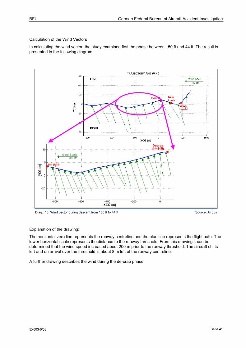
BFU German Federal Bureau of Aircraft Accident Investigation
5X003-0/08 Seite 41
Calculation of the Wind Vectors
In calculating the wind vector, the study examined first the phase between 150 ft und 44 ft. The result is presented in the following diagram.
Diag. 16: Wind vector during descent from 150 ft to 44 ft Source: Airbus
Explanation of the drawing:
The horizontal zero line represents the runway centreline and the blue line represents the flight path. The lower horizontal scale represents the distance to the runway threshold. From this drawing it can be determined that the wind speed increased about 200 m prior to the runway threshold. The aircraft shifts left and on arrival over the threshold is about 8 m left of the runway centreline.
A further drawing describes the wind during the de-crab phase.
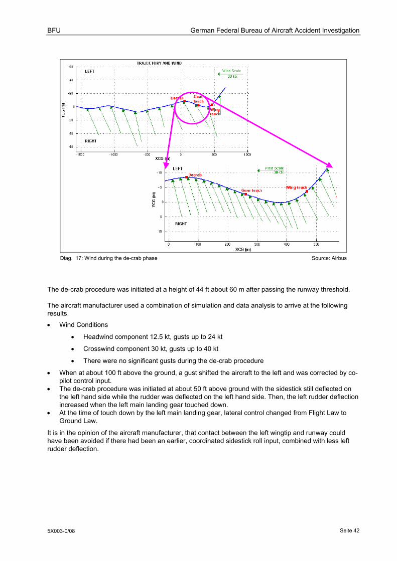
BFU German Federal Bureau of Aircraft Accident Investigation
5X003-0/08 Seite 42
Diag. 17: Wind during the de-crab phase Source: Airbus
The de-crab procedure was initiated at a height of 44 ft about 60 m after passing the runway threshold.
The aircraft manufacturer used a combination of simulation and data analysis to arrive at the following results.
• Wind Conditions
• Headwind component 12.5 kt, gusts up to 24 kt
• Crosswind component 30 kt, gusts up to 40 kt
• There were no significant gusts during the de-crab procedure
• When at about 100 ft above the ground, a gust shifted the aircraft to the left and was corrected by co-pilot control input.
• The de-crab procedure was initiated at about 50 ft above ground with the sidestick still deflected on the left hand side while the rudder was deflected on the left hand side. Then, the left rudder deflection increased when the left main landing gear touched down.
• At the time of touch down by the left main landing gear, lateral control changed from Flight Law to Ground Law.
It is in the opinion of the aircraft manufacturer, that contact between the left wingtip and runway could have been avoided if there had been an earlier, coordinated sidestick roll input, combined with less left rudder deflection.
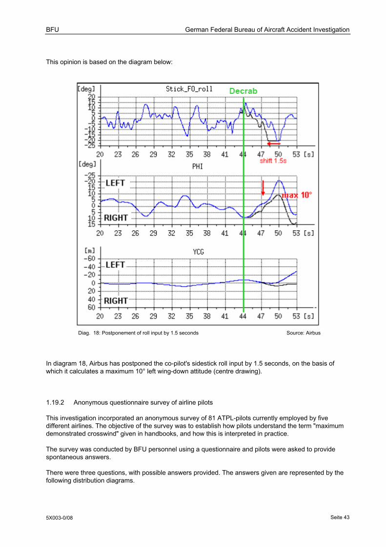
BFU German Federal Bureau of Aircraft Accident Investigation
5X003-0/08 Seite 43
This opinion is based on the diagram below:
Diag. 18: Postponement of roll input by 1.5 seconds Source: Airbus
In diagram 18, Airbus has postponed the co-pilot's sidestick roll input by 1.5 seconds, on the basis of which it calculates a maximum 10° left wing-down attitude (centre drawing).
1.19.2 Anonymous questionnaire survey of airline pilots
This investigation incorporated an anonymous survey of 81 ATPL-pilots currently employed by five different airlines. The objective of the survey was to establish how pilots understand the term "maximum demonstrated crosswind" given in handbooks, and how this is interpreted in practice.
The survey was conducted by BFU personnel using a questionnaire and pilots were asked to provide spontaneous answers.
There were three questions, with possible answers provided. The answers given are represented by the following distribution diagrams.

BFU German Federal Bureau of Aircraft Accident Investigation
5X003-0/08 Seite 44
Question 1: What is the practical meaning for you in normal flight operations of the term "maximum demonstrated crosswind", as stated in OM/B? a) This value is a limit. b) This value is a guide. c) Right now, I am not sure.
Diagram 1: Percentage distribution of answers to question one
Question 2: "Maximum demonstrated crosswind" is the
a) maximum crosswind speed at which the authority of control sur-faces can be maintained during a crosswind landing.
b) maximum crosswind speed that could be demonstrated during Type Certification test flying, due to the weather conditions.
c) maximum crosswind speed that, following test flying, has been set as a representative limiting value for line pilots.
d) Right now, I am not sure.
Diagram 2: Percentage distribution of answers to question two
Question 3: The handbook sets the "maximum demonstrated crosswind" at 33 kt, gusting 38 kt. The crosswind component (gust) for the approach is 40 kt. Which of the following responses is correct:
a) The aircraft may land, if the gusts are assessed as not operationally relevant.
b) The aircraft may not land, be-cause this would exceed the air-craft's operational limitations.
c) Gusts are not to be considered when calculating crosswinds, only the steady wind counts.
d) Right now, I am not sure. Diagram 3: Percentage distribution of answers to question three

BFU German Federal Bureau of Aircraft Accident Investigation
5X003-0/08 Seite 45
2. Analysis
The flight from Munich to Hamburg was a scheduled flight by an air operator conducted in accordance with the legal requirements of JAR-OPS 1 (now EU-OPS). This is intended to set a flight safety standard that ensures the safe conduct of the flight, including unusual weather situations.
The central point of the investigation into this event classified as a Serious Incident, was clarification of the question as to how the aircraft left wingtip could touch the ground during the landing. In this context, the analysis examines those aspects and factors that could have had a direct or indirect effect upon the occurrence: Determination and communication of meteorological information; aircraft handling character-istics during crosswind approaches and landings; flight operations procedures; basic training and refresher training procedures; decision taking processes employed by flight crews and air operators.
The landing was undertaken in the presence of a strong, gusting crosswind; it was a very dynamic situation calling for a high level of flying skill and airmanship.
The investigation showed that wingtip contact with the runway was not due to a single human error, a malfunction of the aircraft or inadequate organisation; rather, it was due to a combination of several factors.
2.1 Operational aspects and history of the flight
2.1.1 Analysis of the flight from the operational viewpoint
From the operational point of view the approach was stable until about eight seconds before touch down. The parameters logged by the flight data recorder and video recording showed no significant wing down attitude by the aircraft. Until the aircraft had descended through 80 ft above ground (radio altimeter) no rudder deflection was required and there was little operation of the ailerons.
As also seen in the video recordings of preceding landing aircraft, the Airbus thereafter drifted to the left under the influence of the crosswind. The co-pilot reacted with right sidestick correction. On descending through 50 ft over the runway threshold, the heading changed 10° right. This correction was appropriate to return the aircraft to the runway centreline.
It was then necessary to counteract this correction so that the aircraft should track along the centreline and avoid a further shift to the right. For this reason, the co-pilot made a left correction with the sidestick; at a height of 20 ft the aircraft was approximately over the centreline with wings level. At the same time, she began the progressive application of left rudder to bring the fuselage into line with the runway (about 70% pedal deflection in the five seconds prior to first touchdown. The combined dynamics of the yaw and roll axes then lowered the left wing until the left main landing gear touched the runway.
Between 30 ft and 25 ft above ground, the co-pilot initiated the flare manoeuvre commensurate with the situation.
On descending through 20 ft the captain reacted to the increasing left wing-down attitude with right sidestick correction. At the same time, the co-pilot shifted her sidestick input from left to right.
BFU German Federal Bureau of Aircraft Accident Investigation
5X003-0/08 Seite 46
The aircraft touched down shortly after the 1,000 ft marker in the touchdown zone, about 2 m left of the runway centreline lights with the left wing 4° down and the fuselage pointed 2° to the right of runwayal-lignment, whereupon the rudder pedals were returned to the neutral position.
The aircraft yawed towards the left, thereby increasing the lift from the right wing and decreasing that from the left wing. In spite of the co-pilot's right sidestick correction, this resulted in unintended contact between the downwind main landing gear and the runway. The objective had been to land with wings level. This was confirmed by the correct application of right sidestick prior to touchdown, which was intuitively supported by the Captain's sidestick (dual input).
After touchdown the aircraft yawed a further 5° to the left. The left main landing gear lost contact with the runway. At no time did the right main landing gear make contact with the runway. Lift dumpers (partial spoiler extension) remained inactive, because the necessary prerequisites were absent.
During the next few seconds the aircraft rolled to a 23° left wing down attitude in spite of the full right deflection of both sidesticks and application of right rudder. The switch to Ground Law limited the effect of roll control corrections. The left main landing gear again made contact with the runway. At about the same instant, the left wingtip made contact with the runway.
Given the high roll rate of the aircraft, the co-pilot made the correct decision to go around and initiated the procedure. She advanced both thrust levers to maximum thrust (TOGA) and correctly called out "Go around" in line with the procedure. This was confirmed by the captain who responded: "Go-around - I have control", as he assumed control of the aircraft.
In the following five seconds the aircraft drifted left over the runway edge with the wings rocking from 23° left wing down to 15° right wing down. The drift terminated with the fuselage over the left edge of the runway. The video film shows water spray thrown up by the efflux from increasing engine thrust. At this time, the height was recorded as 2 ft. The captain stabilised the attitude; the aircraft then made the transition to a slow initial climb above the left half of the runway.
As seen by the BFU this brief period was packed with a complex sequence of events. In this situation, the decision to "Go-Around" and its execution were professional, logical and correct.
The BFU is also of the opinion that, given the crosswind landing technique adopted, the co-pilot was correct in her decision to realign the aircraft fuselage with the runway direction, to touch down with the main gear aligned as near as possible to the direction of motion and with minimum drift. This procedure conforms to the manufacturer's recommendation and the operator's training procedures.
To de-crab the aircraft and bring the fuselage into line with the runway she had to use about 70% full rudder deflection. The value was the result of the drift when approaching touchdown. In crosswind landings it is always a function of aircraft speed, crosswind intensity, and position of the aircraft versus centerline.
It is also possible that her operation of the rudder may have been influenced by what was for her an unusual aircraft attitude during touch down. The possibility cannot be excluded that, from her seat, the right hand runway edge appeared to be directly in front; and her intuitive operation of the rudder was intended to prevent the aircraft running over the edge of the runway.
Ignoring the captain's simultaneous intervention during the landing, the data record shows that during the approach, there were brief sidestick interventions from the left hand side at 110 ft, 100 ft and 75 ft. These may have been barely quantifiable, but they were analogous to the co-pilot's sidestick inputs. The assumption can be made that these inputs were not consciously induced, since the operator's standard procedure on this aircraft type is, that during take-off and approach, the PNF (pilot non flying) should maintain a loose hold of the sidestick in order to be able to take over at any time. At the same time, he used the press-to-talk button incorporated in the sidestick to acknowledge instructions received from air traffic control.

BFU German Federal Bureau of Aircraft Accident Investigation
5X003-0/08 Seite 47
2.1.1 Results - Analysis of the results by the aircraft manufacturer
Essentially, the sequence of events reconstructed by the aircraft manufacturer on the basis of the flight data record, and the account by the flight crew of their control inputs, both agree with the BFU assess-ment.
Within this investigation the wind conditions derived by simulation and calculation were used as additional factual information. This enabled the BFU to work on the assumption that the actual crosswind compo-nent was about 30 kt gusting up to 40 kt. The fact that there were no significant gusts during the de-crab procedure explains that the aircraft was not brought to this unusual and critical attitude by direct external influence.
In this instance, the aircraft was in the classic coordinated cross control situation with simultaneous opposite application of the ailerons and rudder.
However, in this particular case, the ailerons should have been operated prior to the rudder.
The exemplary account of the aircraft manufacturer that, if the co-pilot's sidestick input had been delayed by 1.5 seconds the result would have been a maximum of 10° left wing down -- and would thus have avoided wingtip contact with the ground -- is theoretically understandable. However, from the practical point of view of a pilot, this assessment can be queried. With the aircraft under manual control, a time period of about 1.5 seconds would have been difficult to coordinate precisely. Further, it should be noted that in this specific case a reduction of the wing-down angle to a maximum of 10° would have prevented wingtip contact with the ground; but also that pilots are enjoined to avoid unintended changes in attitude just prior to touchdown. Any unintended wing drop to the left was unacceptable.
The aircraft manufacturer arranged for a simulation and it showed that the wing drop to the ground was prevented by an earlier sidestick input. The evaluation of the simulation's result by the aircraft manufac-turer is plausible and understandable for the BFU.
However, the BFU is still of the opinion that, a crosswind landing procedure requiring the timed and coordinated use of sidestick and measured application of rudder, can only be accomplished with the proper landing technique which should be suitably documented and practised within the pilot training programme.
2.2 Specific Conditions
2.2.1 Flight Crew and Flight Operations
Both pilots were properly licensed and qualified for the flight in question.
The captain as the pilot-in-command was highly experienced, with a total flight time of more than 10,000 hours and over 4, 000 hours on the Airbus A320.
The co-pilot was relatively inexperienced, having a total flight time of 579 hours with 327 hours on the Airbus A320. However, this was commensurate with here age and stage of career. She had concluded a full course of training as an airline transport pilot, passing seamlessly from ab-initio to type-specific training for the Airbus A320 with commensurate simulator check-flights. Not only did she meet the formal requirements; she was also qualified to fly the aeroplane in the normal practical sense for regular line operations. At the time of the incident, she had successfully concluded a course of education and training which suited her for employment in line operations.

BFU German Federal Bureau of Aircraft Accident Investigation
5X003-0/08 Seite 48
The cockpit crew composition was in line with the company's rules and practice, and the requirements of aviation law. From the safety point of view, the relevant factors were sound basic training, the successful completion of training on the Airbus A320, plus the line checks that are standard practice for all commercial pilots. The disparity of experience between the captain and the co-pilot was not unusual, and of itself had no negative influence on the safe conduct of the flight.
Both pilots had experience of crosswind landings during their flying training and in line operations. As a result of his many years experience, the captain also had experience of landings with stronger cross-winds, while it for the co-pilot was the first landing under such crosswind conditions. The general weather situation and the unusually strong gusts represented an exceptional situation for both members of the crew. Neither crew member had previously had the targeted opportunity to practice crosswind landings of this kind under real life conditions in basic flying training, simulator training or check flights. Landings under different crosswind conditions can only take up a limited amount of simulator time because these are just one aspect of the training programme, which also embraces emergencies, unusual situations and system failures. In addition, there are technical limits to the simulator's ability to provide a realistic
During their pre-flight preparation the crew had prepared themselves mentally for the forecast weather conditions. The pilots were well aware and prepared for the situation, thanks to media weather reports with general warnings of strong winds, current weather reports and aviation weather forecasts. During the flight the crew discussed the wind several times. Given the weather situation, the aircraft had been well fuelled (to storm level) and there was no time pressure to make a prompt landing. The fuel on board was sufficient to reach an alternate aerodrome or return to Munich.
The standard weather information was available. In the opinion of the BFU, the captain under-estimated the effect of the crosswind and the possible effect of gusts on the aircrafts controllability in the phase representation of strong crosswinds comparable to these conditions near the ground after a short touch down.
This evaluation needs to take into account, however, that the approach with crosswind information with gusts up to 47 kt was not aborted.
The investigation showed that the pilots could not have been aware of the crosswind flight control characteristics in close proximity to the ground and which were dependent upon the aircraft design. It is impossible to clarify whether the pilots would have taken a decision for a go-around procedure earlier had there been a risk evaluation that included aircraft system behaviour, then unknown to the crew, in this wind situation with the possible effects of gusts. The BFU is of the opinion, that the respective knowledge would probably have influenced the decision.
Up until 20 ft above ground the approach was stabil and exhibited aeronautically no reason for a go-around procedure.
The workload was high for both crew members during the approach to Runway 23, the go-around and the second approach. As pilot flying (PF) the co-pilot had to concentrate upon manual control of the aircraft. The cockpit voice recordings made during the approach indicated that, for at least brief periods, she had almost exhausted her mental resources for further actions and decisions. During the approach, the captain observed her actions and aircraft response. During this period, the captain shared the cockpit workload, confirmed her actions, gave advice and motivational support.
From the voice recording it was evident that the captain was confident in the co-pilot's ability to make a safe landing. There was no discussion of basic matters, such as the choice of a suitable landing technique. The co-pilot used the "wings level" with "de-crab" crosswind landing technique as described in the Handbook (OM/B).
In a subsequent interview with the BFU the captain based his decisions almost completely on the criteria stated in the company's CRM philosophy. In line with this he strived for cockpit teamwork making use of all available resources, and saw himself in the role of monitoring pilot.

BFU German Federal Bureau of Aircraft Accident Investigation
5X003-0/08 Seite 49
His decisions were based on the criteria, requirements and duties given in section 8.3.2 of the company's OM/A setting out flight crew cockpit duties.
The CVR record was evidence of the fact that the core elements behind the company's CRM philosophy were properly implemented:
• Communication
• Leadership and Teamwork
• Workload Management
• Situation Awareness and Decision Making
Given the company's CRM guidelines, the captain's decision to allow the co-pilot to fly the approach was understandable. However, bearing in mind the guidelines contained in OM/A 1.6.1, the BFU views the landing should have been regarded as critical in view of the forecast weather situation. The reason for this is, that the forecast regard to wind called for a landing under conditions defined in OM/B as maximum demonstrated crosswind. Had the captain come to this conclusion, he would have had to undertake the landing himself.
2.2.2 Air traffic controllers
The two air traffic controllers had the required licenses and ratings. In accordance with the standard operating procedures, during the approach of the A320, the aerodrome controller provided the crew with repeated fresh wind reports by radio using the wind values indicated to the tower by the Information Data Processing System.
2.2.3 Decision-taking processes
Given the unusual weather conditions, this flight called for a series of important decisions. The crew had to make a series of rational decisions, some of which were spontaneous and whose consequences were of considerable relevance to the safety of passengers and crew. The investigation, therefore, looked more closely at the following decision processes:
• Pre-flight preparation
• Choice of landing direction
• Go-around
• Alternate airports
• Approach and landing to Runway 33
The investigators considered at the basis on which decisions were taken, the possible alternatives, and peripheral conditions.
2.2.3.1 Pre-flight preparation
In Munich, prior to the flight the crew had access to the usual weather information (METAR, TAF, SIGMET, etc.) enabling them to decide on the feasibility of the flight to Hamburg.
At the departure time, originally planned for 1035 hrs, the then current 1020 hrs routine METAR weather report gave the wind as 280° at 25 kt gusting 45 kt; the published TAF warned of the possibility that gusts
BFU German Federal Bureau of Aircraft Accident Investigation
5X003-0/08 Seite 50
might increase to 45 kt. Armed with this information and the METAR report at the actual departure time of 1150 hrs -- which warned that the wind might gust up to 45 kt -- the crew could assume that a landing at the destination airport was uncertain, and that a diversion to another airport was therefore a possibility.
In addition, the crew had to assume that the wind might temporarily (TEMPO) worsen, because the Aerodrome Forecast (TAF) for the entire afternoon indicated a temporary increase in wind speeds to 30 kt gusting up to 55 kt.
Prior to the departure the DWD had issued a SIGMET report for the Bremen FIR, from which could be seen there was a possibility that the wind and gusts might exceed the values specified in the Limitations chapter of OM/B as the maximum crosswind demonstrated for landing.
An Aerodrome Weather Warning also alerted to a strong wind blowing from west to northwest with speeds of 25 to 30 kt, gusting up to 45 kt and up to 55 kt during the afternoon. This information was not available to the crew since, in accordance with ICAO requirements, it did not form part of the standard briefing package.
The crew decided to proceed with the flight. At any time they had the option to abandon the flight or to fly to one of the planned alternate airports. The operator regarded this procedure and the decision as usual; common the investigation team viewed it as acceptable.
Interpreting the value of maximum crosswind demonstrated for landing given in FCOM as the operating limit for the aircraft -- and noting the fact that wind information does not specify the gust direction (AIP GEN 3.5 Appendix 3) -- in the presence of forecast wind gusts of 55 kt, a landing would not have been permissible on any runway.
A simplified view is that in our latitudes wind in a gust veers 10° to 20° to the right in comparison to the surface wind; in this case, given the wind information quoted in the METAR and the TAF, the crosswind component taken into account for the approach to Runway 23, would have exceeded the maximum crosswind demonstrated for landing speed specified for the aircraft.
Nevertheless it would still have been possible to embark upon the flight to Hamburg. Taking this view, the crosswind component on Runway 33 would have been lower.
The BFU is of the opinion that, the captain as pilot-in-command did not reach his decision using this reasoning, because he did not regard the value maximum crosswind demonstrated for landing as an operational limit for the aircraft. Civil air transport pilots were generally poorly informed about the effects of crosswinds in weather conditions such as these.
Given this unusual weather situation, there was no company operational management support for the crew in their decision taking process prior to or during the flight.
If the company operational management had undertaken a risk evaluation, it would have been able to take into account the weather reports from MAB-Hamburg and the GAMET area forecast produced by the DWD. A detailed description of the general weather pattern and its effects upon lower airspace and near the surface, would possibly have greatly clarified the risk situation.
2.2.3.2 Choice of landing direction
In accordance with the Manual of Operations for Air Traffic Control (BA-FVK) and the criteria in the Standard Operating Procedures (BAO), the air traffic controller had decided that Runway 23 was in use.
The final responsibility for the choice of runway was that of the pilot-in-command. He decided on an approach to Runway 23 even though Air Traffic Control offered Runway 33 as an alternative. He incorporated the co-pilot in the decision process.

BFU German Federal Bureau of Aircraft Accident Investigation
5X003-0/08 Seite 51
The main reasons for this decision were the wind information available, and the values documented in the Chapter Operating Limitations of OM/B A319/A320/A321, and given as "maximum crosswind demon-strated for landing 33 knots gusting up to 38 knots".
Because of the general weather situation, during the cruise phase of the flight the crew obtained repeated weather updates by listening to the Hamburg ATIS to follow the current situation. The broadcast ATIS "W" transmitted at 1250 hrs was one of the main reasons for their choice of Runway 23, which reported the wind as 280° / 23 kt, gusting up to 37 kt, with good visibility occasionally reduced to 4 km. The same ATIS broadcast "W" obtained in preparation for the landing reported the wind might increase from time to time from 25 kt in gusts to 45 kt with the direction unchanged at 280°, and that the ILS was in operation for Runway 23.
Given the wind information then available, the choice of Runway 23 was logical. If the approach had instead been made to Runway 33 using the wind information broadcast in ATIS "W" the aircraft would have suffered the same crosswind component but from the left side.
Likewise, the decision to land on Runway 23 was further justified by the fact that the published approach procedure Runway 33 was a non-precision procedure. An approach to Runway 23 with vertical ILS guidance guaranteed a more stable approach. The aircraft was not equipped and certified for GPS guidance
During the cruise phase of the flight and when preparing their decision on the choice of landing direction, the ATIS "W" broadcast forecast a surface wind for Runway 23 of 280° / 23 kt gusting up to 37 kt. The wind values were below the maximum values specified in OM/B. Given these conditions, the decision was understandable.
2.2.3.3 Go-around
Using all the available known and published information, the crew decided upon an ILS approach to Runway 23.
However, the ATIS "W" information giving the wind strength as 25 kt and the remark that there could be gusts up to 45 kt, might have raised a question against their decision to land on Runway 23. The crew did not regard the values 33 knots gusting up to 38 knots given in OM/B as a flight operations limit and therefore began their approach.
The next ATIS "Y" broadcast at 1320 hrs reported the wind as 290°/28 kt gusting up to 48 kt, temporarily 35 kt and gusting up to 55 kt; but this broadcast was not heard by the crew because the aircraft was already under radar control and positioned downwind for an approach to runway 23. Likewise, they did not notice the subsequent non-routine ATIS "Z" broadcast, which differed from that of ATIS "Y" in bearing the message that Runway 33 was also now available for use.
When on approach to Runway 23 the Tower passed messages giving the wind as 300°/28 kt gusting up to 47 kt, and 290°/29 kt gusting up to 47 kt, from which it was self-evident that during the entire approach the crew could expect gust speeds above the maximum crosswind demonstrated for landing of 38 kt published in OM/B.
From the question put to the Aerodrome controller as to the proportion of go-arounds -- to which the answer was 50% -- the BFU refers that the captain was aware that that the approach and landing were demanding. He decided to make an approach, with the option of a go-around at any time. During the final phase of the approach the wind veered to 300°, so that at this time the wind direction was more favourable for Runway 33.
In the opinion of the BFU, the approach briefing should have been determined when and under what crosswind conditions the go-around must be initiated. If the requirement had been that the crew must regard the demonstrated crosswind for landing as a limit, the go-around would have been initiated prior to
BFU German Federal Bureau of Aircraft Accident Investigation
5X003-0/08 Seite 52
the landing, because the wind report given by the tower exceeded these limits. During the approach briefing, discussion was limited to the possibility of a go-around but without setting minima, which are a requirement for a go-around in bad weather.
The BFU estimates the crew did not interpret the maximum crosswind demonstrated for landing given in OM/B and the Limitations chapter of FCOM as being prescribed operating limits for the aircraft, or as company limitations. Nor was consideration given to the fact that the value quoted for gusts did not fall within the classification of the two-minute average value (e.g. 290°/29 kt) -- and in accordance with current teaching, in our latitudes could be an additional 20° to the right -- but was the maximum value for the past previous ten minutes. Because the crosswind was from the right for the intended landing, the crosswind component was increased during the gusts. This inference was justified by the captain's statement, that in his perception the effect of the gusts was greater than expected and forecast. Also, with the benefit of hindsight, the aircraft had been close to its operating limits.
For an assessment within the context of this investigation, the following aspects were relevant:
• In order to incorporate the reported gusts into the decision taking process to make an approach to land a comparison of the approach requirements set out by the operator (in OM/B) and the aircraft manufacturer (in FCOM) was nessecary.
• In the opinion of the BFU, there are three possible variants: 1. A consideration limited solely to the numerical value of gust speeds. 2. The assumption that gusts are from the same direction as the surface wind. 3. The assumption that gusts are from the same direction as the surface wind plus 10-20° (North-
ern hemisphere). In all three cases, the gust speeds and crosswind components, respectively, were between 41 and 48 kt, and, therefore, clearly above the speed of 38 kt.
2.2.3.4 Alternate diversion airports
The flight plan gave Billund Airport in Denmark as the diversion airport. The Billun runway direction is 09/27 and the wind there was West to Northwest, making it suitable for a diversion.
From the interview with the crew and the CVR recording it was evident that they had not considered a diversion to Billun. The aircraft had been refuelled in Düsseldorf with additional reserves in view of the weather conditions; it is more probable that the aircraft would have diverted to Southern Germany. Given these ample fuel reserves, the crew was not under any time pressure.
In the the opinion of the BFU, the crew did not regard the wind situation as being so critical that they could not attempt an approach. However, the crew did see the landing as demanding and were more prepared than usual to initiate a go-around, as was discussed in considerable detail at the approach briefing.
2.2.3.5 Approach and Landing to Runway 33
After the go-around from Runway 23, the crew decided to land on runway 33 because the change in wind direction then appeared to make the conditions more favourable. The crew disregarded the issue of gusts, which by then had increased to 40 kt and were therefore beyond the demonstrated crosswind limitations for this approach, when treated without directions.
The winds reported by the Tower during the approach to Runway 33 (300°/ 33 maximum 50; 290°/ 32 maximum 49; 290°/28 maximum 49; and 290°/27 maximum 49 knots) were again well above 38 kt. However, given the different wind directions reported (300° and 290°) and the assumption that the gusts were from the same direction, the crosswind components were between 8.7 kt and 31.5 kt, i.e. values well below 38 kt.
BFU German Federal Bureau of Aircraft Accident Investigation
5X003-0/08 Seite 53
The approach and landing were flown by the co-pilot, who was well aware that this would be a demanding task and expressed her reservations to the captain. From the CVR voice recording the BFU gained the impression that she would have preferred to leave the landing to the captain. After he assured her of his support and assistance, she agreed to do the landing.
2.2.4 Aircraft design-dependent system behaviour (Control Laws)
During this occurrence, aircraft lateral control behaviour (control about the longitudinal roll axis) was determined by the transition from Flight Mode to Ground Mode when the left main landing gear touched down. The moment the left main landing gear touched down the two LGCIUs detected that the gear was lowered and loaded. Also, at the same moment the radar height altimeter detected that the aircraft was less than 50 ft above ground.
The lateral control system condition thus met all the requirements for the transition from Flight Mode to Ground Mode, so, the system switched from lateral Flight Mode to lateral Ground Mode. The system was so designed that when in lateral Ground Mode the ailerons/spoilers kinematics are modified as a function of speed, in the sense to reduce the maximum available ailerondeflection by half (at high speed: > 80k)t. This was also confirmed by the Flight Data Recorderparameter traces, in which aileron deflection was reduced to about half of full travel in responseto full sidestick deflection. The preexisting Yaw-Compensation was not functional anymore. The BFU is of the opinion that this system arrangement was part of the reason why the aircraft could enter an unintended and unforeseen flight attitude and why the situation could not be prevented through counteractive sidestick control input. The activated sensor on the left main landing gear (ground sensor) signalled the system that the aircraft was in a flight attitude in which it was not. The system switched in lateral control into Ground Mode, although the aircraft was still in the air. This produced a situation in which the system functionality was not unambiguous.The BFU regards this as safety relevant.
Evaluating the flight operations documentation it was noted that the description given in FCOM "The lateral control mode does not change until the wheels are on the ground, so there is no discontinuity in the control laws" is inaccurate. The investigation into this occurrence has determined that the switch in Control Laws takes place when a single main landing gear touches down.
Activation of the ground spoilers would have required both main landing gears to touch the ground.
Operational consequences
It can be assumed that the one-sided touchdown with the left main landing gear was not intended. This is confirmed by the correct reactive operation of the sidestick prior to touchdown.
After the aircraft lost contact with the runway and then suddenly adopted a 23° left wing down attitude, the co-pilot and captain reacted immediately with application of full right sidestick and up to 14° right rudder. It is possible that rudder operation was intuitive reinforcement, because the aircraft was moving towards the left side-edge of the runway and sidestick operation had no visible effect in halting this drift. The effect was not that which the pilots had expected. The Flight Data Recorder trace showed that the right aileron was raised up to 6°, the left aileron lowered as far as 15°, and the right roll spoiler was raised only up to 8°. The reason for this is to be found in the aileron control system mentioned above; the control system was in Ground Law mode, as a result of which control surface deflection was limited by the Flight Control System logic.
The manufacturer justified the system design with the argument that, unless the effect of the flight controls was limited, the landing could result in pilot induced oscillation. The BFU regards this as

BFU German Federal Bureau of Aircraft Accident Investigation
5X003-0/08 Seite 54
understandable, but criticises the fact that the logic and system description are not described in any handbook, and were thus unknown to pilots or training departments.
The BFU views the system design described as a design-dependent problem for landings with strong crosswinds, especially when making the transition from Flight Mode to Ground Mode and the aircraft touches down and then loses contact with the ground again. This situation is not at all unusual in crosswind landings. To ensure absolute clarity of lateral control -- i.e. Flight Mode in the air and Ground Mode on the runway -- simultaneous touchdown of both main landing gears has be a mandatory requirement. In regular operations, especially under crosswind conditions, this requirement would not always be easily met. Also, the simultaneous touchdown of both main landing gears would be in conflict with the crosswind landing technique described by the manufacturer after this occurrence
2.2.5 Weather
Weather forecast
On the day in question the weather forecast products required under ICAO Annex 3 were supplied by the DWD and were available to aviator customers.
The air operator's dispatch department handed over a compilation of aviation weather information as described in ICAO Annex3, Chapter 9 to the crew, to prepare the meteorological aspects of their flight planning.
The forecasts (TAFand GAMET) essentially agreed with the actual weather conditions at the time of the occurrence. The TAF wind speeds of up to 55 kt were clearly above the actual wind at the time of the occurrence.
The sub-FL100 FIR Bremen GAMET area forecast valid for the period between pre-flight preparation and the incident incorporated – in addition to the information in Section I, notification of potentially dangerous weather en route – in section II PHYS, details of the pressure system such as its position and direction of movement (1200 UTC, low 964 hPa southern of Sweden moving south east, weakening, 1200 UTC moving south east through line Denmark-Netherlands, no change, 1200 UTC occlusion line south of Sweden-Lithuania –– east of Poland – Switzerland, moving south east no change). The DWD advises that AIRMETs are only issued if there are one or more weather hazards that are not forecast in the routine GAMET. For the period of the flight in question, the information was published in the GAMET, for which reason the DWD did not issue an AIRMET.
The crew did not have the information from the GAMET forecast.
Given the presence of turbulence classified as severe, the DWD issued SIGMETS at 0900 and 1229.
Although the air operator's subsidiary companies were equipped with the pc_met system, at the time of the incident, the parent company did not. Nor were the Fax-Download or INFOMETservices called upon on the day in question.
The BFU is of the opinion that, it would have been helpful to make use of the weather data to supplement that contained in Chapter 9 of ICAO Annex 3. The BFU formed the opinion that, the provision of GAMET forecasts would have been the only way in which the crew would have received the weather warnings contained in Section I for those sections of the flight conducted below FL100 (FL150). The BFU further concludes that, the detailed description of the pressure system contained in Section II would have been useful to the crew in regard to the decision taking process.
The general requirements stated in the Air Operator's OM/A said that the crew could consult an aviation weather forecaster for a personal briefing upon request. In addition, the crew was required to obtain a personal or telephone briefing from an aviation weather forecaster if there was a threat of a typhoon or

BFU German Federal Bureau of Aircraft Accident Investigation
5X003-0/08 Seite 55
hurricane. The BFU is of the opinion that, consideration should be given to the possibility of a weather briefing from the appropriate weather service in the face of extreme weather conditions.
The reason given as to why the crew was not provided with the GAMET forecast, is viewed by the BFU as a discrepancy in ICAO Annex 3.
Within the meaning of Annex 3, AIRMET warnings and GAMET forecasts are meteorological products for lower airspace up to FL100/FL150 and are not intended to be for a particular target group. Many pilots regard GAMET forecasts as being intended solely for General Aviation. There is a similar perception for AIRMET. However, the BFU holds that, AIRMET warnings and GAMET forecasts, SECN I are relevant to all aircraft flying through the airspace concerned. Whilst AIRMET reports are listed in Chapter 9 as being part of the material required for preparation of the meteorological aspects of a flight, GAMET forecasts are not listed. This could result in the loss of important items of meteorological information.
Limiting the issue of AIRMETs to those instances in which the significant weather features have not yet been forecast in GAMET SECN I requires, in the view of the BFU, instructions that ensure the content of the GAMET forecast is known to all pilots. This could be achieved by adding the GAMET forecast to the meteorological information listed in ICAO Annex 3, Chapter 9.
Wind
The table for Hamburg Airport gives an overview of the number of days each month in which the wind speed reached 41knots or more (storm). It shows that in the years 1993 to 2007 there was an average of 7.4 days per year in which the wind reached such speeds. There were five such days in the period 1 January to 1 March 2008. The wind conditions pertaining on the day of the incident were significant, but not unusual.
Gusts
ICAO Annex 3 and AIP Chapter GEN 3.5, Appendix 3, state that in general no direction is given for gusts. It is understandable that, given the definition of gusts and the measuring method described in Annex 3, it is not possible to state the accurate direction from which gusts may be expected.
The three variants listed in section 2.2.3.3 of this report, describe how the pilots could have interpreted the gust information on the day of the occurrence and are valid in a general sense. However, in the opinion of the investigation team, each one is problematic in line operations with strong crosswind conditions.
Taken by itself, the numerical value of the gust speed is academic, because whenever a gust is forecast it could occur as a tailwind. Only gusts exceeding 10 kt have to be reported. As a precautionary measure, one would have to assume that each gust could occur as a tailwind and therefore all landings would have to be ruled out.
From the point of view of the aviation meteorologist and the measuring method, the assumption that a gust might come from the same direction as the current surface wind is incorrect. The wind report given by the Tower is always a two-minute average value. If a gust speed is quoted, it is the strongest value to have occurred in the previous ten-minute window. Gusts happen –– provided they are not linked with synoptic weather events or orographic features –– as a result of air mixing in the vertical plane. Although in everyday operations many pilots seek to determine the direction from which gusts may arise, this method is questionable, in particular in the presence of stormy conditions and strong crosswinds.
Similarly, the assumption that the gust direction would be that of the current surface wind plus 10-20° is of little use in practice because in general this only holds good in the Northern hemisphere, but is invalid for terrain with sharp orographic features, thunderstorms, thermal weather conditions or during the passage of fronts. Pilots cannot always be informed in detail about peripheral conditions such as the orographic circumstances of individual airports.

BFU German Federal Bureau of Aircraft Accident Investigation
5X003-0/08 Seite 56
In the absence of advice on how to deal with gusts, in everyday operations the worldwide practice is to assume that gusts will arise from the same direction as the current wind.
The BFU formed the opinion that, the question of how to deal with gusts in everyday operations has not yet been sufficiently explained in a manner that would help pilots in practice.
2.3 Defences
Defences are measures to protect a system from the consequences of technical and/or human error. In this system, the human does not operate in isolation, but is one element in a complex socio-technical system.
During the analysis of this Serious Incident, the data stated in the aircraft operating limitations, the data in the crosswind landing documentation, and the landing technique specified by the aircraft manufacturer and air operator, were viewed and evaluated as essential safety mechanism.
2.3.1 The air operator's crosswind landing requirements
The requirements stated in OM/A, OM/B and OM/C were binding for pilots. The air operator had issued general instructions with respect to flight limits under crosswind landing conditions.
The formulation: “The steady crosswind and gust component for take-off and landing must not exceed the values specified in OM-B and OM-C. Where no gust limit is specified, gust exceeding crosswind limitations must be considered whenever judged operationally significant.” was not interpreted by the crew as a flight operations limit.
An anonymous survey of more than 80 pilots revealed that about half regarded the numerical value of the maximum demonstrated crosswind stated in OM/B as a limit, while the other half regarded the numerical value as a guide; this indicates to the BFU that there is a need for clarification. Likewise, the distribution of answers to question three, as to whether a landing should be allowed in the presence of a 40 kt gust report, highlights pilot uncertainty about the application and interpretation of the numerical value of the maximum demonstrated crosswind.
The BFU views one possible reason for uncertainty in the use of the numerical value of maximum demonstrated crosswind as the way in which this is presented in OM/B, where the value of 33 kt gusting 38 kt is associated with the observation maximum demonstrated crosswind for landing, but like FCOM was included in the Chapter Operating Limitations.
There was no explanation or definition given for the term maximum demonstrated crosswind for landing.
2.3.2 The aircraft manufacturer's requirements for crosswind landings
The aircraft manufacturer set out the flight limitations, operating instructions and descriptions for the aircraft type in the Flight Crew Operating Manual (FCOM) and Flight Crew Trainings Manual (FCTM). The information contained in these manuals formed the basis for the contents of Operating Manuals OM/A to OM/D set out by the operator in accordance with the requirements of EU-OPS.

BFU German Federal Bureau of Aircraft Accident Investigation
5X003-0/08 Seite 57
With respect to crosswind landing limitations, the aircraft manufacturer stated:
“Wind for takeoff and landing:
Maximum crosswind demonstrated for takeoff: 29 knots gusting up to 38 knots
Maximum crosswind demonstrated for landing: 33 knots gusting up to 38 knots”
documented in the Chapter on Operating Limitations in FCOM, Vol 3.
This description and its position within FCOM was adopted by the Air Operator as part of Operating Manual OM/B; thus, for this aircraft, it represented the basis of information for pilots and the training department
It is the opinion of the BFU, that the term maximum crosswind demonstrated for landing was not defined or described in any detail in FCOM. This led to different interpretations and misunderstandings. Misinterpretation was aided by use of the word "demonstrated" in association with the numerical value 33 knots gusting up to 38 knots, although this numerical value was placed in the Chapter Operational Limitations.
From the entry in the FCOM manual it was not clear that from the point of view of the aircraft manufac-turer, this was solely an item of information with respect to the speed value flown (demonstrated) during flying while in pursuit of the Type Certificate. The aircraft manufacturer's explanation, that the air operator should set an internal company limit in accordance with his own general conditions and spectrum of operations, was not clearly spelled out and no part of the formal aeronautical regulation process.
In the Flight Manual (FM), which should be, among other things, basis for the FCOM showed in chapter Performance, General for maximum demonstrated crosswind at takeoff and landing: 38 kt (gust included) the indication ”This value is not considered limiting”.
It is logical from the aircraft manufacturer's standpoint that the aircraft operator should define his own maximum value for crosswind take-offs and landings in the OM/B, since this enables the operator to set limits on his own responsibility that accord with his own operational aspects, plus the possible difference in training and qualifications of the crews.
The differences in the descriptions given for crosswind landing values across the Airbus fleet, and for a single type, are a disadvantage. The value quoted for the Airbus A320 is 33 kt, gust 38, while for the Airbus A340 it is 40 kt including gust.
2.3.3 Demonstration of compliance during type certification (Certification Specification)
The investigation into this Serious Incident and the associated anonymous survey of licensed commercial pilots revealed that the maximum crosswind demonstrated for landing documented in the FCOM and OM/B standard handbooks are interpreted differently and can be misunderstood. The fact that about one half of all respondents viewed this value as a limit, and the other half viewed it as a guideline, is evidence of a considerable information deficit. Likewise, the answers to the questions on the permissibility of landings in gusty conditions call for clarification.
The different descriptions and explanations given by the operator and aircraft manufacturer in a range of operating and training manuals, were partly due to the inadequate definition and explanation of the term maximum crosswind demonstrated for landing given in the Certification Specification and in the instructions for their implementation.
During the course of this investigation it was not retraced in detail, how the A320 aircraft manufacturer demonstrated practical compliance for the maximum crosswind demonstrated for landing. The aircraft

BFU German Federal Bureau of Aircraft Accident Investigation
5X003-0/08 Seite 58
manufacturer explained that demonstration of compliance was carried out using technical equipment and procedures of a higher standard than required in the Certification Specification and Flight Test Guide Material.
Nevertheless, the BFU regards this subject as a fundamental problem in the Certification Regulation and instructions for their implementation. The choice to verify and display a value for the maximale crosswind component as demonstrated or limiting led to discrepancies in their implementation and applicationn.of value for the maximum crosswind component to document compliance as demonstrated or limiting, has led to distractions in their implementation and application. A value that was quoted for compliance within the framework of Type Certification as demonstrated, was also published in the Limitations chapter of FCOM. The situation is that the maximum crosswind value given for some types of aircraft is seen as a limit not to be exceeded, while on other aircraft this same speed is documented solely as a demonstrated value, led to different interpretations by the respondent pilots in different airlines.
This event brought to light the safety-relevant aspects of crosswinds. The BFU holds that, the expression "33 kt with gusts up to 38 kt" was also problematic. The Certification Specification allowed for this type of description, although to show compliance there was no requirement that gusts up to this value actually occurred during the certification process. The definition of gusts and the associated measuring methods allowed safety relevant inaccuracies, especially when wind reports were given by the tower. For example, using this method no reports would be given or taken into account of gusts less than 10 kt. So, it was quite possible that a wind 33 kt (average wind) report with gusts up to 38 kt (including gusts) would be of little practical value.
The different descriptions given for maximum crosswind demonstrated for landing with respect to the different types of aircraft within the Airbus family gave further rise to confusion among pilots. The crosswind values for several aircraft types were given as two values (average wind speed and gust), while for others the value was given as a single value (average wind speed including gust) (Appendix 10). Both forms were allowed under the construction regulations.
2.3.4 Manufacturer's description of crosswind landing procedures
The landing incident that is the subject of this investigation took place in a strong and gusty crosswind; it was a highly dynamic manoeuvre calling for a high degree of pilot handling skill and airmanship. Given this situation it was essential that the landing technique prescribed by the aircraft manufacturer for this aircraft should be presented uniformly, comprehensively, clearly and intelligibly in all flight operations documentation.
The description of the crosswind landing technique to be adopted should form the basis for crew training. Because landings in very strong and gusty crosswinds are not an everyday occurrence in scheduled operations, a clear description of the procedure to be adopted by flight crews and for the basis of training purposes was of great importance. For this reason the landing procedure described in the Flight Crew OperationsMmanual (FCOM) should be identical with that given in the Flight Crew Training Manual (FCTM).
The same holds true for other publications such as the FCOM bulletin, FOBNs and other documentation. In addition, the descriptions given in FCOM and in FCTM served the operator as the basis upon which to issue the instructions contained in Operations Manuals OM/B and OM/D.
The investigation showed that the crosswind landing procedure descriptions (crab-angle, sideslip or a combination) given in the flight operations documentation FCOM, FCTM, FCOM bulletins and FOBN, were not uniform and partly contradictory.
BFU German Federal Bureau of Aircraft Accident Investigation
5X003-0/08 Seite 59
For example, there were different descriptions given as to use of rudder. FCOM-Bulletin No. 827/1 stated:
• “Use of rudder, combined with roll inputs, should be avoided, since this may significantly increase the pilot’s lateral handling tasks. Rudder use should be limited to the “de-crab” maneuver in case of crosswind, while maintaining the wings level, with the sidestick in the roll axis.”
FCOM Bulletin No. 828/1 commented on the use of rudder as follows:
• “[…]
• During landing flare with crosswind, for decrab purposes.
• During the landing roll, when on ground.
In these circumstances, large and even rapid rudder inputs may be necessary to maintain control of the aircraft.”
Rudder inputs were in the case at hand of importance because the aircraft manufacturer had determined during their analysis that the rudder inputs had been too fierce and abrupt. This result contravenes with the descriptions in some operational manuals.
IIt is the opinion of the BFU that, the crosswind landing technique prescribed in FCOM and FCTM – and hence also in OM/B – was less suitable for strong crosswind conditions. In the presence of a crosswind greater than 20 kt, this landing technique with the fuselage longitudinal axis aligned with the runway and wings level resulted in the aircraft drifting away from the runway centreline.
The Flight Operation Briefing Notes (FOBNs) contained the description of a landing technique that would have been suitable for use in a strong crosswind such as that in Hamburg. In the case of a crosswind greater than 20 kt, the FOBN recommends an approach with the right wing slightly down (5°) and the fuselage angled about 5° into the wind; this prevents the aircraft drifting away from the runway centreline and ensures that the aircraft touches down first with the windward main landing gear. However, this procedure was not found in the FCOM. The description given in the FOBN was clear and concise, but was in contradiction to the descriptions given in other flight operations documentation. This FOBN was not known to all pilots; within the context of the flight operations documentation it was merely of an informative nature.
After the Serious Incident in Hamburg there was a discussion of crosswind landing technique between the aircraft manufacturer, the operator and the BFU, following which the manufacturer declared its intention to re-word the description of the landing technique and amend all relevant flight documentation accordingly (Appendix 10).
2.3.5 The Air Operator's description of crosswind landing procedure
The Operations Manuals (OM) required by the approval and monitoring authorities in accordance with EU-OPS were of great and outstanding importance for the operation of this aircraft by the company. The OMs have the status of type-related non-discretionary working instructions for the crew, and describe the processes required for safe conduct of the flight. This includes the description of the crosswind landing technique.
The investigation showed that the description of the crosswind landing technique stated in OM/B and OM/D did not completely match the description given in the manufacturer's documentation. There were also differences between the descriptions given in OM/B and OM/D.

BFU German Federal Bureau of Aircraft Accident Investigation
5X003-0/08 Seite 60
The analysis of the company's flight operations documentation determined that the instructions
• ”In strong crosswind conditions, small amounts of lateral control may be used to maintain the wings level.”
• ”This lateral stick input must be reduced to zero at first main landing gear touchdown.”
were documented in OM/B, but these instructions were not given in the aircraft manufacturer's FCOM, Vol 3.
The BFU is of the opinion that if the crew had followed the company's flight operations instruction "This lateral stick input must be reduced to zero at first main landing gear touchdown", it would have resulted in an even greater left wing-down attitude in the particular circumstances of this landing.
Research by the BFU indicates that the above-mentioned instruction formed part of A320-FCOM 3, Revision 38. The aircraft manufacturer cancelled this in the next revision, but there followed no such change to OM/B.
Further instructions within OM/B are based on FCOM-Bulletins, from which individual sections or sentences were abstracted.
It was not completely clear from the available documentation which of the FCOM bulletins or parts thereof were incorporated into OM/B. Likewise, the background and reasons for the changes to OM/B were unclear.
The crosswind landing technique described in OM/B and FCOM was less suitable for use in very strong crosswind conditions. The landing technique described was to align the fuselage longitudinal axis with the runway, keeping the wings level. If the crosswind were greater than 20 kt this resulted in the aircraft drifting from the runway centreline.
The crosswind landing technique described by the operator's training syllabus OM/D was the combined wings low with crabbed approach. This would have been more suitable for a landing in a strong crosswind.
Although this landing technique was not documented in the OM/B, the operator advised the BFU that it was taught and practised in the simulator.
It is the opinion of the BFU that, it was inappropriate, in terms of safe conduct of the flight, for pilots to select a personal preference from the range of crosswind landing techniques published in different parts of the flight documentation

BFU German Federal Bureau of Aircraft Accident Investigation
5X003-0/08 Seite 61
2.4 Organisational aspects
On the day of the occurence the weather situation was significant and represented a challenge to the flight crew that was well above normal. On the other hand, the weather situation was not so unusual as to have been classified as an unforeseeable event.
Other than the standard instructions Handling of airplane on the ramp in strong wind conditions, the flight crew were provided with no situational aids to pre-flight preparation or in-flight operation. Nor was there any organised unit within the company to provide crews with specialist advice relating to this particular weather situation in Germany and Europe, or to make decisions based on the company's central overall view and responsibilities.
Neither the aviation regulations, nor the company's internal procedures and policies, envisaged the provision of specialist advice or instructions that could be superimposed on decisions by the pilot-in-command.
The BFU holds that, this Serious Incident showed that for example, the following infrastructure measures could have contributed towards the safe conduct of the flight:
• Definition of extreme weather conditions (e.g. surface wind with gusts > xx kt, typhoon, heavy rain etc.)
• Extended weather briefing (e.g. GAMET, MAB, ….)
• Requiring the nomination of additional alternate airfields
• Supplementary despatch services (including during the flight)
• The assembly of specialist teams (MET, ATC, OPS) in the face of extreme weather situations
• Creation of a management-level decision-taking arrangement (temporary cessation of flight op-erations by the company's aircraft; cancellation of flights)
• Operational rules for extreme weather situations (Captain is PF, …)
BFU German Federal Bureau of Aircraft Accident Investigation
5X003-0/08 Seite 62
3. Conclusions
3.1 Findings
Flightpath reconstruction
• The approach was stable up to about eight seconds before touchdown. Given the effect of the wind, the sidestick inputs were logical.
• Given the situation, the flare was initiated correctly at a height of between 30 ft and 25 ft above ground.
• The left main landing gear touched down first with the fuselage about 2 m left of the runway centre-line; the left wing was 4° down, and the fuselage offset 2° into wind from the right.
• The left main landing gear lifted off again. At no time did the right main landing gear touch the ground.
• The aircraft left wing dropped to an angle of about 23° in spite of full right sidestick deflection by both pilots and right rudder..
• The left main landing gear touched down again and the left wing made contact with the ground.
• Given the high rate of roll, the co-pilot initiated the go-around.
• The aircraft manufacturer simulated and calculated the incident, and concluded that there had been no significant gusts during the de-crab procedure.
Crew and flight operational aspects
• The crew was properly licensed and qualified for the flight.
• By virtue of his many years of flying, the captain had previous experience with strong crosswind situations.
• This was the first occasion on which the co-pilot had landed an Airbus A320 under such large crosswind influence.
• The weather situation with unusually strong gusts was an exceptional situation for both members of the flight crew.
• There was no basic training exercise, or simulator training and check procedure, in which real life situations could be practised.
• Prior to the flight, the crew had mentally prepared themselves for the weather situation.
• The aircraft had ample fuel reserves and the flight crew was under no pressure to make an early landing.
• The usual weather briefing services were available both prior to the flight and during the approach.
• The pilots could not have been aware of the specific flight system control response characteristics during a landing with a gusty crosswind und were, therefore, unable to incorporate it into their deci-sion taking process.
• The workload was very high for both members of the crew during the approach to Runway 23 and go-around. At times during the approach, the co-pilot almost reached the limit of her mental re-serves for further actions and decisions.
BFU German Federal Bureau of Aircraft Accident Investigation
5X003-0/08 Seite 63
• The co-pilot decided to adopt the "Wings Level" and "De-crab" crosswind approach technique. This crosswind landing technique was described in OM/B.
• The captain cited instructions given in the company's CRM philosophy as the principal reason for his actions in the cockpit and decisions.
• The elements making up the company's defined requirements for CRM interpersonal competence were applied and implemented.
• In this instance it would have been appropriate to classify this landing as a "critical landing" within the meaning of the description given in OM/A 1.6.1. So that, the captain would have been person-ally tasked with making the landing as pilot flying (PF).
• During the final approach to land the tower reported the crosswind as gusting up to 47 knots, and the aircraft continued the approach. In view of the maximum crosswind demonstrated for landing, a Go-Around would have been reasonable.
• Up until about 20 ft above ground and based on the progress of the approach, the crew saw no reason to abort it.
• Provoked by the significant bank angle in close proximity to the ground, the go-around was initiated immediately.
ATC
• The air traffic controller had the necessary licenses and ratings for the task in hand.
Aircraft (Lateral control)
• When the left main landing gear first touched the runway, the lateral control system condition thus met all the requirements for the transition from Flight Mode to Ground Mode, so, the system switched from lateral Flight Mode to lateral Ground Mode even though the aircraft was once again in the air.
• The aircraft was designed so that the effect of lateral controls (along the longitudinal axis) would reduce by about one half of full deflection as soon as one main landing gear touched down.
• The reduced effect of controls was not documented in the system description and was unknown to pilots or the training department.
• During the landing, the aircraft's system behaviour contributed to a flight attitude which was unintended and undesired by the pilots and ground contact with the wingtip could not be prevented anymore.
Manuals and type certification
• The crew did not interpret the formulation given in the OM/A instruction “The steady crosswind and gust component for take-off and landing must not exceed the values specified in OM/B and OM/C. Where no gust limit is specified, gust exceeding crosswind limitations must be considered when-ever judged operationally significant.” as a flight operational limit. The gusts were not viewed as a limiting factor.
• The survey of commercial pilots showed that there are very different interpretations of the cross-wind information given in OM/A, and that there is a considerable information deficit with respect to the term maximum crosswind demonstrated for landing.
• OM/B and FCOM Vol. 3 described "33 kt gusting up to 38 kt", was described as the maximum crosswind demonstrated for landing, but was positioned in the chapter Operating Limitations.
• In the FM, 33 knots gusting up to 38 knots was denoted as demonstrated and accorded the signifi-cance of "Information".
BFU German Federal Bureau of Aircraft Accident Investigation
5X003-0/08 Seite 64
• In the FM and FCOM the term maximum crosswind demonstrated for landing was not defined or explained.
• The air operator had not laid down a specific gust speed as the ultimate limit for crosswind landings in the Airbus A320.
• The instructions for implementation of the construction regulations CS 25.233 (Directional stability and control) und CS 25.237 (Wind velocities) allowed for demonstration of compliance both for a defined limit and as a guideline (demonstrated).
• The construction implementation instructions stated that the use of the term demonstrated was to be accorded the status of "information".
• The construction implementation instructions for setting the crosswind landing limits or guidelines, respectively, permitted a method of compliance demonstration which did not take into full account the real effect of crosswinds.
• The values for maximum crosswind demonstrated were presented differently for different types within the Airbus family (average wind speed plus gusts, average wind speed including gusts).
Landing techniques
• The description of different crosswind landing techniques (crab-angle, sideslip or a combination) contained in flight operations documentation FCOM, FCTM, FCOM Bulletins and FOBN were not uniform and in part contradictory.
• The crosswind landing description given in FCOM was less suitable for use in very strong cross-winds, because it could result in the aircraft drifting from the runway centreline.
• There were different descriptions given in the aircraft manufacturer's flight documentation with respect to the use of rudder in crosswind conditions.
• One Flight Operation Briefing Note (FOBN) described a technique for landing in strong cross-winds that would have been suitable for the Hamburg landing in question.
• The Flight Operation Briefing Note was not part of the official operating manuals. • The description of the crosswind landing technique given in the company's OM/B and OM/D
manuals did not match completely the one given by the aircraft manufacturer in the FCOM. • There were differences between the landing techniques described in OM/B and OM/D. • Under strong crosswind conditions the wings low with crabbed approach technique described in
OM/D would have been more suitable. • The landing technique described in OM/D was taught and practised in the simulator.
Weather
• The weather information prescribed for pre-flight preparation was provided by the DWD and available to the crew.
• The weather conditions at the time of the occurrence essentially matched those of the forecast. • The wind conditions on the day of the occurrence were significant but not unusual. • The reported wind speeds were not viewed as a limiting factor during the descicion taking proc-
ess regarding the continuation of the approach. • Wind reports given to landing aircraft incorporate no indication of the direction from which gusts
may arise. • A gust speed report (without indication of the direction) is open to different interpretations by
pilots. • Because of the ambiguous formulation given in ICAO Annex 3, the crew did not receive the
meteorological information contained in the GAMET forecast.
Organisational aspects
• In spite of the significant weather situation, the crew was not provided with any supplementary help in making their decisions.

BFU German Federal Bureau of Aircraft Accident Investigation
5X003-0/08 Seite 65
• The company did not have an internal organisation to provide the crew with additional advice in the face of unusual weather conditions, and which could take decisions based on company policy and internal perception of its own responsibilities.
• A special weather advisory unit within the company was not called for, provided or required by law, nor by the company's internal rules.

BFU German Federal Bureau of Aircraft Accident Investigation
5X003-0/08 Seite 66
3.2 Causes
This serious landing incident took place in the presence of a significant crosswind and immediated causes are as follows:
• The sudden left wing down attitude was not expected by the crew during the landing and re-sulted in contact between the wingtip and the ground.
• During the final approach to land the tower reported the crosswind as gusting up to 47 knots, and the aircraft continued the approach. In view of the maximum crosswind demonstrated for landing, a go-around would have been reasonable.
The following systematic causes led to this serious incident:
• The terminology maximum crosswind demonstrated for landing was not defined in the Operating Manual (OM/A) and in the Flight Crew Operating Manual (FCOM), Vol. 3, and the description given was misleading.
• The recommended crosswind landing technique was not clearly described in the aircraft standard documentation.
• The limited effect of lateral control was unknown.
4. Safety Recommendations
On 20 March 2009 the BFU issued the following safety recommendations to the aircraft manufacturer:
Recommendation No.: 12/2009
The aircraft manufacturer should take immediate steps to ensure that the landing technique most recently described (March 2009) should be incorporated in the flight operations documentation for the Airbus Types A318/A319/A320/A321. The descriptions given in FCOM, FCTM, in the FCOM Bulletins, FOBNs and all other documents should be uniform, clear and understandable without any contradictions.
Recommendation No.: 13/2009
Should it not be possible to implement recommendation 12/09 without delay for editorial reasons, or for reasons of unalterable amendment procedures for the respective flight documents, the aircraft manufacturer should inform all operators of the Airbus Types A318/A319/A320/A321 without delay and in suitable form, about the circumstances of this serious Serious Incident and the planned changes.
BFU German Federal Bureau of Aircraft Accident Investigation
5X003-0/08 Seite 67
On 20 March 2009 the BFU made the following safety recommendation to the operator:
The operator advised the BFU in writing on 7 April 2009 that Safety Recommendations No. 14/2009 and No. 15/2009 would be applied with immediate effect.
On 20.03.2009 the BFU made the following Safety Recommendation to the Luftfahrt-Bundesamt (German Civil Aviation Authority):
Recommendation No.: 14/2009
It must be ensured that the crosswind landing technique described in the Operations Manual, Part B (OM/B), Chapter 2, is the same as the instructions and descriptions given by the aircraft manufacturer.
When incorporating supplements and background information that are not incorporated in the aircraft manufacturer's FCOM documentation into the description of crosswind landing techniques, the working process and an associated quality assurance (QA) procedure should be described and applied; the QA procedure should ensure plausibility and correctness of the instructions and check for the absence of instructions and descriptions that are contrary to those of the aircraft manufacturer.
Recommendation No.: 15/2009
It must be ensured that the crosswind landing technique given in the Operations Manual, Part D (OM/D) is not in conflict with that described in OM/B.
Recommendation No.16/2009
The Luftfahrt-Bundesamt should ensure that maximum crosswind take-off and landing speeds are set for German Air Operators.
Within the context of flight operations management, all air operators should examine the handbooks provided by different aircraft manufacturers for different aircraft types and study how the handbook wording maximum crosswind demonstrated is interpreted and acted upon.
Whren indicated, an instruction should be issued based on EU-OPS 1.015 to require that maximum crosswind values be set for crosswind take-offs and landings.

BFU German Federal Bureau of Aircraft Accident Investigation
5X003-0/08 Seite 68
The BFU has issued the following Safety Recommendations:
Recommendation No.: 01/2010
The aircraft manufacturer should initiate an assessment for the Aircraft Type A320 and Series with the aim that the transition logic Flight Mode/Ground Mode of the lateral control system switches into Ground Mode only if the aircraft is indeed on the ground.
At the same time the updated landing technique in strong crosswind conditions should be taken into account. Furthermore, it should be ensured that such a change will not limit or impede existing system functionalities for other situations.
Recommendation No.: 02/2010
The aircraft manufacturer should, as a transitory action (until the Safety Recommendation No. 01/2010 has come into effect), amend the system descriptions for the lateral control in the flight operations documentation (FCOM, etc.) and training documentation for the Aircraft Type A320 and Series indicating that under certain circumstances limited rudder deflection may occur during landings.
The explanation in the system description for the transition logic Flight Mode/Ground Mode in the FCOM “The lateral control mode does not change until the wheels are on the ground, so there is no discontinuity in the control laws.“ should be rectified.
Recommendation No.: 03/2010
The aircraft manufacturer of the Aircraft Type A320 and Series should remove the term maximum crosswind demonstrated for landing from the chapter Operating Limitations, also from the respective Flight Crew Operating Manuals (FCOM), all other flight operation instructions and information references, and place this elsewhere.
The aircraft manufacturer’s flight operations documentation should incorporate the guidance that this value bears the character of ’Information’.
The aircraft manufacturer should adopt a uniform presentation of maximum crosswind demonstrated for landing for the entire range of the same series of aircraft. The maximum crosswind demonstrated for landing should be described either as a dual value (average wind speed and gust) or as a single value (average wind speed including gusts).
Manufacturers should make recommendations to air operators as to the suitable maximum crosswind component for landings.

BFU German Federal Bureau of Aircraft Accident Investigation
5X003-0/08 Seite 69
Recommendation No.: 04/2010
EASA should revise the Flight Test Guide Material requirements contained in the Certifica-tion Specifications CS 25.233 (Directional stability and control) and CS 25.237 (Wind velocities) to define and elucidate the term maximum crosswind demonstrated for landing. The definition adopted should make clear that this value has the character of ‘Information’, and that the same uniform terminology is adopted throughout all instruction documentation relating to flight operations.
Air operators should be advised to set operational crosswind limits for their own specific operations.
The value should be described either as a dual value (average wind speed and gust) or as a single value (average wind speed including gusts).
Recommendation No.: 05/2010
EASA should initiate an amendment to EU No. 859/2008 (EU-OPS) requiring special operating procedures for for the operation of civil aircraft by airlines engaged in public transport activities in the presence of extreme weather situations
In addition to provisions and decision guidance air operators should establish an organisa-tional structure or unit to provide assistance to crews for pre-flight preparation and in-flight support, when faced with defined (extreme) weather conditions. If necessary, the organisa-tional structure or unit must take the decision to cancel a flight for reasons of weather.
In this context, the pilot-in-command's power of decision should remain unaffected.
Recommendation: 06/2010
EASA should place a contract with a suitable research institute (DLR, University or similar) to determine what measuring systems are suitable to detect the presence of near-surface gusts on airports, and how the resulting gust data and wind direction information should be processed and communicated to pilots. The results should lead to a process through which the information so obtained can be standardised and incorporated into the regulations governing air operations.
Recommendation No.: 07/2010
The International Civil Aviation Organisation (ICAO) should amend Annex 3 to require the incorporation of GAMET and AIRMET meteorological services in Chapter 9, to ensure the optimum provision of meteorological information to crews engaged in public transport duties for pre-flight preparation.
BFU German Federal Bureau of Aircraft Accident Investigation
5X003-0/08 Seite 70
Braunschweig, March 2010
On behalf of the Federal German Aircraft Accident Investigation Bureau
Johann Reuss
Investigator-in-charge
The following persons took part in the investigation:
Operations / Human Factors specialists: Lothar Müller / Karsten Severin
Airport/ATC / Meteorology specialists: Jens Friedemann
Data specialist: George Blau

BFU German Federal Bureau of Aircraft Accident Investigation
5X003-0/08 Seite 71
5. Appendices
Appendix 1: Excerpt video recording
Appendix 2: Measured wind values, Anemometer Runway 15
Appendix 3: Measured wind values, Anemometer Runways 23 and 33
Appendix 4: Calculated crosswind components
Appendix 5: FDR data
Appendix 6: Flight Manual (Maximum demonstrated crosswind at takeoff and landing)
Appendix 7: FCOM (Maximum demonstrated crosswind at takeoff and landing)
Appendix 8: OM/B (Maximum demonstrated crosswind at takeoff and landing)
Appendix 9: Maximum demonstrated crosswind at takeoff and landing within the Airbus Family
Appendix 10: Amended description of crosswind landing technique
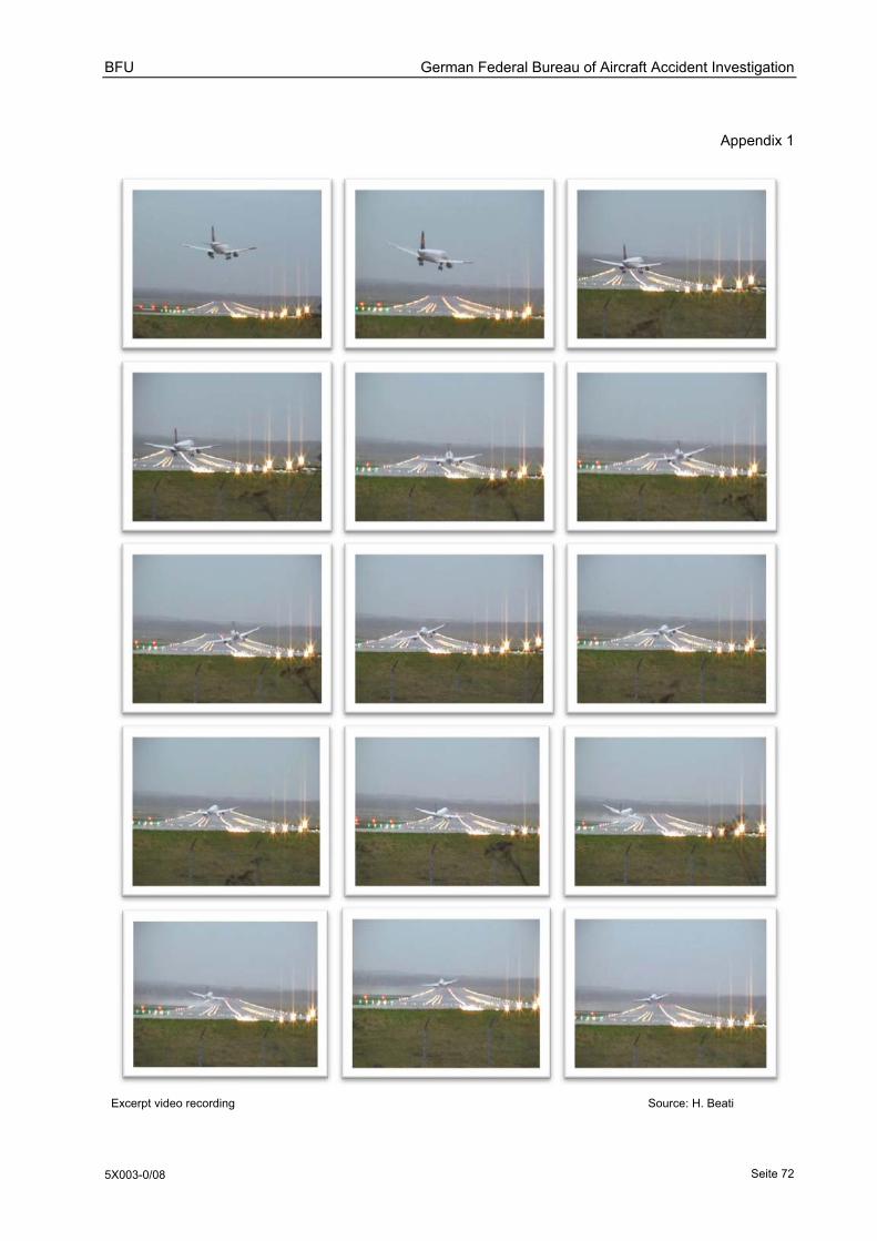
BFU German Federal Bureau of Aircraft Accident Investigation
5X003-0/08 Seite 72
Appendix 1
Excerpt video recording Source: H. Beati

BFU German Federal Bureau of Aircraft Accident Investigation
5X003-0/08 Seite 73
Appendix 2
Wind 10 min. Highest Values Wind 2 min. Mean Value
Time Wind Direction between (°)
Wind Speed min. (kt)
Wind Speed max. (kt)
Wind Direction (°)
Wind Speed (kt)
13:31:00 323 268 18 47 296 27
13:31:10 323 268 18 47 295 37
13:31:20 323 268 18 47 294 27
13:31:30 323 268 18 47 292 28
13:31:40 323 268 18 47 293 29
13:31:50 323 268 18 47 294 29
13:32:00 323 268 18 47 295 29
13:32:10 323 268 18 47 294 30
13:32:20 323 268 18 47 25 31
13:32:30 323 268 18 47 295 32
13:32:40 323 268 18 47 296 32
13:32:50 323 268 18 47 297 33
13:33:00 323 268 18 47 298 33
13:33:10 323 268 18 47 299 33
13:33:20 323 268 18 47 299 33
13:33:30 323 268 18 47 300 33
13:33:40 323 268 18 47 299 32
13:33:50 323 268 18 47 300 32
13:34:00 323 268 18 47 299 32
13:34:10 323 268 18 45 300 32
13:34:20 323 268 18 45 300 32
13:34:30 323 268 18 45 300 32
13:34:40 323 268 18 45 299 32
13:34:50 323 268 18 45 299 31
13:35:00 323 268 18 45 298 32
Anemometer wind measurements in the area of thresholds Runways 23 and 33 on 1 March 2008 between 13:31:00 hrs and 13:35:00 hrs

BFU German Federal Bureau of Aircraft Accident Investigation
5X003-0/08 Seite 74
Appendix 3
Wind 10 min. Highest Values Wind 2 min. Mean Value
Time Wind Direction between (°)
Wind Speed min. (kt)
Wind Speed max. (kt)
Wind Direction (°)
Wind speed (kt)
13:31:00 338 242 8 38 294 21
13:31:10 338 242 8 38 292 22
13:31:20 338 242 8 38 291 22
13:31:30 338 242 8 38 293 22
13:31:40 338 242 8 38 295 22
13:31:50 338 248 8 38 296 21
13:32:00 338 248 8 38 297 21
13:32:10 338 248 8 38 297 20
13:32:20 338 248 8 38 295 21
13:32:30 338 248 8 38 293 22
13:32:40 338 248 8 38 290 23
13:32:50 338 248 8 43 288 24
13:33:00 338 248 8 43 289 24
13:33:10 338 248 8 43 289 24
13:33:20 338 248 8 43 290 25
13:33:30 338 248 8 43 292 24
13:33:40 338 248 8 43 291 26
13:33:50 338 248 8 43 290 26
13:34:00 338 248 8 43 290 27
13:34:10 338 248 8 43 290 28
13:34:20 338 248 10 43 290 28
13:34:30 338 248 18 43 291 27
13:34:40 338 248 18 43 292 27
13:34:50 338 248 18 43 294 26
13:35:00 338 248 18 43 294 26
Anemometer wind measurements in the area of threshold Runway 15 on 1 March 2008 between 13:31:00 hrs and 13:35:00 hrs

BFU German Federal Bureau of Aircraft Accident Investigation
5X003-0/08 Seite 75
Appendix 4

BFU German Federal Bureau of Aircraft Accident Investigation
5X003-0/08 Seite 76
Appendix 5
Diagram of relevant FDR data Source: BFU

BFU German Federal Bureau of Aircraft Accident Investigation
5X003-0/08 Seite 77
Appendix 6
Maximum demonstrated crosswind for takeoff and landing in the FM Source: Airbus
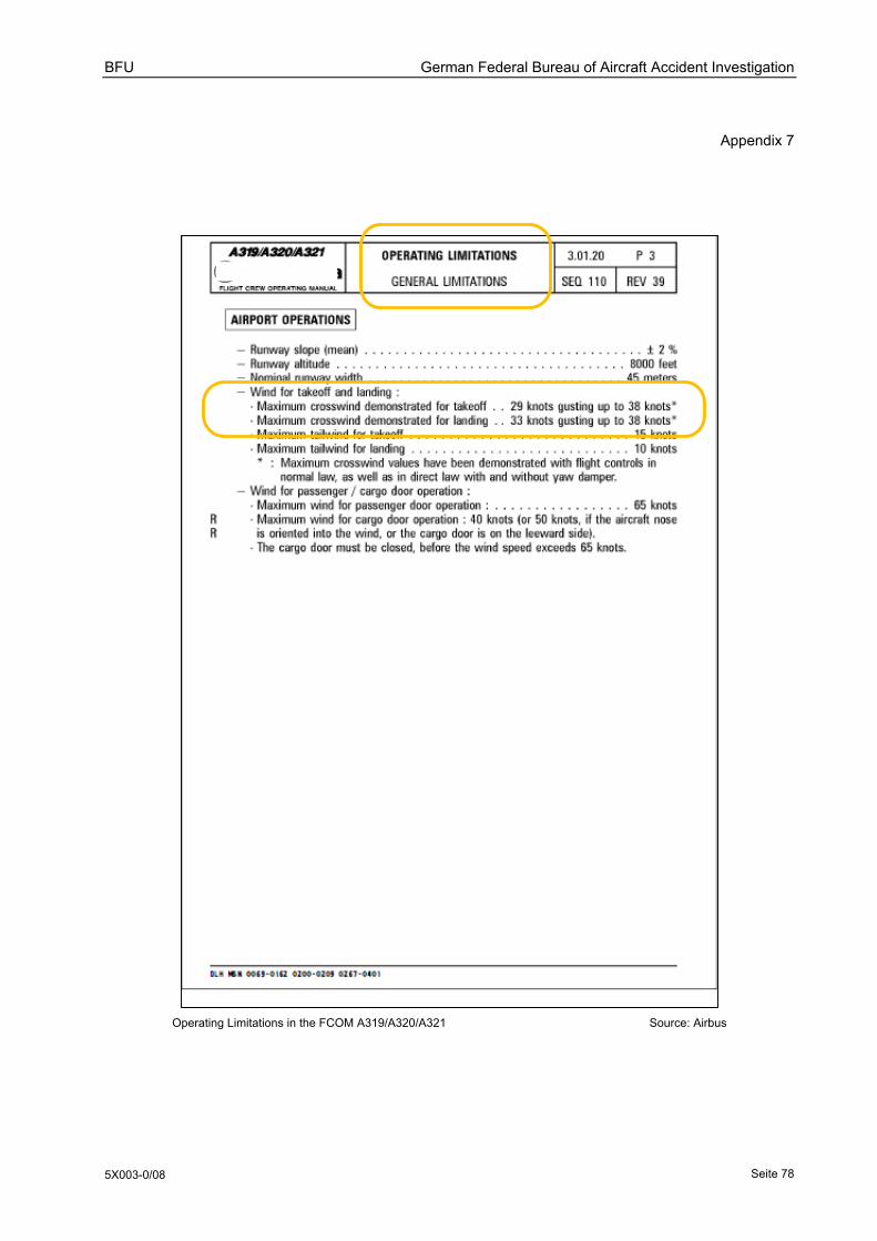
BFU German Federal Bureau of Aircraft Accident Investigation
5X003-0/08 Seite 78
Appendix 7
Operating Limitations in the FCOM A319/A320/A321 Source: Airbus
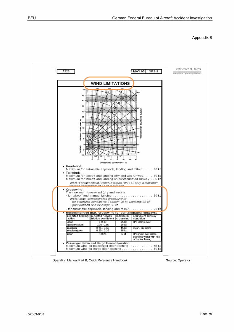
BFU German Federal Bureau of Aircraft Accident Investigation
5X003-0/08 Seite 79
Appendix 8
Operating Manual Part B, Quick Reference Handbook Source: Operator

BFU German Federal Bureau of Aircraft Accident Investigation
5X003-0/08 Seite 80
Appendix 9
Aircraft Flight Manual
A318/319/320/321
Certification: A319/320/321
MAXIMUM DEMONSTRATED CROSSWIND
• Stabilized conditions Take-off 29 kt Landing 33 kt
• gust (T/O and LD) 38 kt
A318/319/320/321
Certification: A318
MAXIMUM DEMONSTRATED CROSSWIND AT TAKEOFF AND LANDING
• At takeoff: 39 kt(gust included) • At landing: 38,5 kt (gust included)
These values are not considered limiting.
A330
Certification: A330
MAXIMUM DEMONSTRATED CROSSWIND AT TAKEOFF AND LANDING
• stabilized conditions: 32 kt (T/O and LD) • gust: 40 kt (T/O and LD) These values are not considered limiting.
A340
Certification: A340-200/-300
MAXIMUM DEMONSTRATED CROSSWIND AT TAKEOFF AND LANDING
• stabilized conditions: 27 kt • gust (T/O and LD): 33 kt These values are not considered limiting.
A340
Certification: A340-500/-600
WIND SPEED LIMITS
The maximum tail wind component is 10 kt
The maximum crosswind component for takeoff is 35 kt (stabilized and gust)
MAXIMUM DEMONSTRATED CROSSWIND AT LANDING
At Landing: 37 kt (gust included)
This value is not considered limiting.
Maximum demonstrated crosswind at takeoff and landing within the Airbus- Family Source: BFU

BFU German Federal Bureau of Aircraft Accident Investigation
5X003-0/08 Seite 81
Appendix 10
Amended description of the crosswind landing technique Source: Airbus