investigation report - asc.gov.tw · investigation report ... the cabin pressure control was...
TRANSCRIPT

Aviation Safety Council
Investigation Report
Korean Air Flight 691
AIRBUS A300-B4-622R, HL-7297
Loss Cabin Pressure at FL320, 30 NM South of Waypoint SALMI
On Route B-576, Taipei FIR
On May 11, 2006
ASC-AOR-07-10-001
OCTOBER 01, 2007

This Page Intentionally Left Blank
ii ii
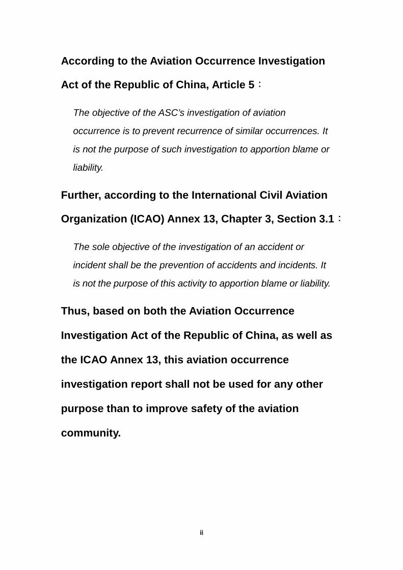
According to the Aviation Occurrence Investigation
Act of the Republic of China, Article 5:
The objective of the ASC’s investigation of aviation
occurrence is to prevent recurrence of similar occurrences. It
is not the purpose of such investigation to apportion blame or
liability.
Further, according to the International Civil Aviation
Organization (ICAO) Annex 13, Chapter 3, Section 3.1:
The sole objective of the investigation of an accident or
incident shall be the prevention of accidents and incidents. It
is not the purpose of this activity to apportion blame or liability.
Thus, based on both the Aviation Occurrence
Investigation Act of the Republic of China, as well as
the ICAO Annex 13, this aviation occurrence
investigation report shall not be used for any other
purpose than to improve safety of the aviation
community.

iii iii
This Page Intentionally Left Blank

i i
Executive Summary
On May 11, 2006 at 0046 UTC1 (Coordinated Universal Time), Korean
Air (KAL) flight number KE0691, an AIRBUS A300-B4-622R aircraft with
registration number HL-7297, departed from Incheon International Airport,
Republic of Korea to Chiang Kai Shek International (CKS) Airport, Taipei,
Taiwan, Republic of China (ROC) The flight departed with128 occupants
on board including 117 passengers, 9 cabin crew members and 2 flight
crew members.
About 0217 UTC, the KE0691 encountered the situation of loss of cabin
pressure while cruised at FL 320, 30 NM south of SALMI2 on route
B576,Taipei Flight Information Region(FIR). The flight crew executed
emergency descent by following the QRH (Quick Reference Handbook).
The 230 out of 267 passenger oxygen masks were dropped automatically
during emergency descent. The aircraft was level-off at 10,000 feet and
the cabin pressure control was recovered after flight crew reset the
system. The aircraft landed safely at CKS airport. No aircraft damage and
occupants on board sustained injury in this occurrence.
According to the Aviation Occurrence Investigation Act, and Annex 13 to
the Convention on International Civil Aviation (Chicago Convention),
which is administered by the International Civil Aviation Organization
(ICAO), the Aviation Safety Council (ASC), an independent agency of the
ROC government responsible for civil aviation occurrence investigation,
composed a team to conduct the investigation of this occurrence. The
investigation team included members from the ROC Civil Aeronautical
Administration (CAA), the Korean Air, the Bureau D’enquetes et
D’analyses pour la Securite de L’aviation Civile (BEA) the state of
1 Taipei Local Time is UTC +8 hrs, and Incheon Local Time is UTC +9 hrs. 2 SALMI: Way point on route B-576, Taipei FIR.

ii ii
manufacture, the Korean Aviation and Railway Accident Investigation
Board (Korean ARAIB) the state of operator, were invited as the
Accredited Representatives (AR) of this investigation based on ICAO
Annex 13.
The investigation was accomplished on 01 August 2007, based upon the
analysis by the Safety Council, the following are the key findings of the
KE0691 accident investigation.
Findings as the result of this Investigation
The Safety Council presents the findings derived from the factual
information gathered during the investigation and the analysis of the
KE691 accident. The findings are presented in three categories: findings
related to probable causes, findings related to risk, and other
findings.
The findings related to the probable causes identify elements that
have been shown to have operated in the occurrence, or almost certainly
to have operated in the occurrence. These findings are associated with
unsafe acts, unsafe conditions, or safety deficiencies that are associated
with safety significant events that played a major role in the
circumstances leading to the occurrence.
The findings related to risk that have the potential to degrade aviation
safety. Some of the findings in this category identify unsafe acts, unsafe
conditions, and safety deficiencies that made this occurrence more likely;
however, they can not be clearly shown to have operated in the
occurrence. They also identify risks that increase the possibility of
property damage and personnel injury and death. Further, some of the
findings in this category identify risks that are unrelated to the occurrence,

iii iii
but nonetheless were safety deficiencies that may warrant future safety
actions.
Other findings identify elements that have the potential to enhance
aviation safety, resolve an issue of controversy, or clarify an issue of
unresolved ambiguity. Some of these findings are of general interest and
are not necessarily analytical, but they are often included in ICAO format
occurrence reports for informational, safety awareness, education, and
improvement purposes
The findings related to the probable causes
1. A broken flange in the automatic mode motor drive component
caused the FWD outflow valve failed and the subsequent failure
of both auto modes in driving the FWD outflow valve. The failed
valve in both auto modes caused the cabin pressure loss.
2. The flight crew did not apply the manual mode to control the
cabin pressure.
3. There is no integrated procedures defined when both of cabin
pressure regulators failed and rapid decompression happened,
whether the flight crew shall continuously complete the “CABIN
PRESS REG FAULT” procedure or direct to the “EMERGENCY
DESCENT” procedure.
The findings related to risk
1. The flight crew did not follow the standard procedure to initiate a
turn when conducted the “EMER DESCENT” procedure.
Other findings
1. The flight crew members were properly certified and qualified in
accordance with applicable Korean Civil Aviation Regulations.

iv iv
2. There was no evidence indicating the crew had any physical or
psychological problems, nor any use of alcohol or drugs.
3. The aircraft was operated within allowable weight and balance
limitations.
4. There were no adverse weather conditions at the time of the
occurrence.
5. The LIEBHERR AEROSPACE did not conduct more detailed
exploration on that damaged flange of the motor drive
component.
Safety recommendations
To Korean Air
1. Ensure the flight crew to follow the specific emergency
procedures and enhance the operating proficiency.
(ASC-ASR-07-10-001)
2. Review and integrate the related emergency procedures to the
loss of cabin pressure. (ASC-ASR-07-10-002)
To Korean Minstry of Construction & Transportation
1. Monitor and survey the safety recommendation #1 and #2 to
Korean Air. (ASC-ASR-07-10-003)
To LIEBHERR-AEROSPACE/France
1. Conduct more detailed exploration on the damaged flange of the
motor drive component(ASC-ASR-07-10-004)
v v
Contents
Executive Summary ..................................................................... i
Contents ...................................................................................... v
Tables ........................................................................................ vii
Figures........................................................................................ ix
1 Factual Information......................................................... 1
1.1 History of Flight .............................................................. 1
1.2 Injury to Persons ............................................................ 2
1.3 Personnel Information .................................................... 3
1.3.1 Background and Experience of Flight Crew ................ 3 1.3.1.1 The Captain (CM-1)........................................ 3 1.3.1.2 The First Officer (CM-2).................................. 3
1.3.2 Flight Crew’s Medical Conditions ................................ 4 1.3.2.1 The Captain (CM-1)........................................ 4 1.3.2.2 The First Officer (CM-2).................................. 4
1.3.3 72 Hour History........................................................... 4 1.3.3.1 The Captain (CM-1)........................................ 4 1.3.3.2 The First Officer (CM-2).................................. 5
1.4 Aircraft Information ......................................................... 5
1.4.1 General Information .................................................... 5 1.4.2 Maintenance Records ................................................. 6
1.4.2.1 Outflow valves maintenance Requirements.... 6 1.4.2.2 Malfunction records ........................................ 7
1.4.3 Maintenance Action..................................................... 7 1.4.4 Related Systems......................................................... 8
1.4.4.1 Cabin Pressure Control System ..................... 8 1.4.4.2 Cockpit Warning System .............................. 11 1.4.4.3 Passenger Oxygen System.......................... 12 1.4.4.4 Prerecorded Announcements ....................... 13
1.4.5 Weight and Balance.................................................. 14
1.5 Meteorological Information ........................................... 14
1.6 Flight Recorders ........................................................... 15
1.6.1 Cockpit Voice Recorder............................................. 15 1.6.2 Flight Data Recorder................................................. 15 1.6.3 Radar Track .............................................................. 15

vi vi
1.7 Survival Aspects ........................................................... 16
1.8 Test and Research ....................................................... 17
1.8.1 Inspection of FWD out flow valve assembly .............. 17
1.9 Additional Information................................................... 19
1.9.1 Summary of Interview with Flight Crew ..................... 19 1.9.1.1 Flight crew.................................................... 19
1.9.2 Summary of Operation Manuals................................ 22 1.9.2.1 Flight Operations Manual ............................. 22 1.9.2.2 Flight Crew Operating Manual...................... 25
1.9.3 Summary of Quick Reference Hand Book................. 30
2 Analysis ......................................................................... 33
2.1 General ........................................................................ 33
2.2 Related factors ............................................................. 33
2.2.1 Cabin pressure control .............................................. 33 2.2.2 Flight crew disposition procedures ............................ 34
2.3 Others .......................................................................... 36
2.3.1 Emergency descent procedure ................................. 36
3 Conclusions .................................................................. 37
3.1 The findings related to the probable causes ................. 38
3.2 The findings related to risk............................................ 38
3.3 Other findings ............................................................... 38
4 Safety recommendations ............................................. 41
4.1 Safety recommendations.............................................. 41
Appendix1 DFDR tabular data and plots...................... 43
Appendix2 Radar track and plots ................................. 47
Appendix3 Out Flow Valve Assembly Test Result ...... 57

vii vii
Tables
Table 1.2-1 Injury table .................................................................. 2
Table 1.3-1 Basic Information of Flight Crew ................................. 3
Table 1.4-1 Basic information of the aircraft .................................. 5
Table 1.4-2 Basic information of the engines................................. 6
Table 1.4-3 Maintenance Requirements of out flow valve.............. 6
Table 1.4-4 Basic information of the FWD out flow valve............... 7
Table 1.4-5 KE0691 Weight and Balance Data............................ 14

viii viii
This Page Intentionally Left Blank

ix ix
Figures
Figure 1.1-1 Flight path of the KE0691.......................................... 2
Figure 1.4-1 BITE test results........................................................ 7
Figure 1.4-2 Pressure Control System .......................................... 9
Figure 1.4-3 Motor drive components.......................................... 10
Figure 1.4-4 Out flow valve control modes .................................. 11
Figure 1.4-5 Priority Block Diagram............................................. 14
Figure 1.8-1 Normal flange.......................................................... 18
Figure 1.8-2 Damaged flange...................................................... 18

x x
This Page Intentionally Left Blank

1 1
1 Factual Information
1.1 History of Flight
On May 11, 2006 at 0046 UTC3 (Coordinated Universal Time), Korean
Air (KAL) flight number KE0691, an AIRBUS A300-B4-622R aircraft with
registration number HL-7297, departed from Incheon International Airport,
Republic of Korea to Chiang Kai Shek International (CKS) Airport, Taipei,
Taiwan, Republic of China (ROC) The flight departed with128 occupants
on board including 117 passengers, 9 cabin crew members and 2 flight
crew members.
About 0217 UTC, the KE0691 cruised at FL 320, 30 NM south of SALMI4
(Figure 1.1-1) on route B-576, Taipei Flight Information Region(FIR). The
“CAB PRESS REG #2 FAULT” message appeared on ECAM (Electronic
Centralized Aircraft Monitoring) accompanied with chime signal. The
message confirmed by flight crew from the indicated cabin vertical speed
which showed +1,000 feet per minute and the cabin altitude continually
increasing passed 9,000 feet. After the CM-2 switched off the SYS 2 by
following the “ECAM Action”, the “CAB PRESS REG #1 FAULT”
message appeared on ECAM. The cabin vertical speed increased to
+3,000 feet per minute and cabin altitude passed over 10,000 feet. And
then flight crew executed emergency descent by following the QRH
(Quick Reference Handbook). The 230 out of 267 passenger oxygen
masks dropped out automatically during emergency descent. The aircraft
was level-off at 10,000 feet and the cabin pressure control was recovered
after flight crew reset the system. The aircraft landed at about 0302 UTC
safely at CKS airport. No aircraft damage and occupants on board
sustained injury in this occurrence.
3 Taipei Local Time is UTC +8 hrs, and Incheon Local Time is UTC +9 hrs. 4 SALMI: Way point on route B-576, Taipei FIR.

2 2
Figure 1.1-1 Flight path of the KE0691
1.2 Injury to Persons
There were 2 flight crew members, 9 cabin crew members and 117
passengers on board. Non of the occupants on board sustained injury in
this occurrence.
The injury distribution is summarized in Table 1.2-1.
Table 1.2-1 Injury table
Injuries Crew Passengers Others Total
Fatal 0 0 0 0
Serious 0 0 0 0
Minor/None 0/11 0/117 0/0 0/128

3 3
Total 11 117 0 128
1.3 Personnel Information
1.3.1 Background and Experience of Flight Crew
1.3.1.1 The Captain (CM-1)
CM-1 is a nationality of the Republic of Korea who had served in military
as a pilot and no records of flight time history during his military service.
He joined KAL in Feb. 1996. He completed and passed the first officer
flight check of A300-600 in May 2004, and was promoted to a captain of
A300-600 in March 2005. His total flight time to date of the occurrence
was 6,688:00 hours which included 1,320:00 hours on A300-600.
1.3.1.2 The First Officer (CM-2)
CM-2 is a nationality of the Republic of Korea. He joined KAL in April
2005 and started the initial training of A300-600 in April 2005. He
completed and passed the first officer flight check of A300-600 in April
2006. His total flight time to date of the occurrance was 533:00 hours
which included 172:00 hours on A300-600.
Table 1.3-1 Basic Information of Flight Crew
Item CM-1 CM-2
Gender Male Male
Age as of Occurrence 42 30
Date of joining in KAL Feb. 12,1996 Apr. 25, 2005
License type Airline Transport Pilot
No.1623
Commercial Pilot
No. 5012
Type rating
Expiry date
A300-600
Oct. 31, 2006
A300-600 F/O
Aug. 31, 2006

4 4
Medical class
Expiry date
1st class airman
Oct. 31, 2006
1st class airman
Aug. 03, 2006
Latest flight check Sep. 01, 2005 Apr. 13, 2006
Total flight time 6688:00 533:00
Flight time in last 12 months 610:00 175:00
Flight time in last 90 days 161:00 122:00
Flight time in last 30 days 30:00 30:00
Flight time in last 7 days 5:47 12:17
A300-B600 flight time 1320:00 172:00
Flight time on the day of occurrence 2:20 2:20
Rest time before Occurrence Over 24 hrs 13 hrs
1.3.2 Flight Crew’s Medical Conditions
1.3.2.1 The Captain (CM-1)
There is no limitation note on the Airman Medical Certificate issued by
Korea authorities.
1.3.2.2 The First Officer (CM-2)
There is no limitation note on the Airman Medical Certificate issued by
Korea authorities.
1.3.3 72 Hour History
1.3.3.1 The Captain (CM-1)
CM-1 conducted local flight from 1810(0910 UTC) to 2130(1230 UTC) on
May 09 and stayed at home for rest on May 10. He departed from home

5 5
to Incheon International Airport at around 0600 local time on May 11(2100
UTC on May 10) to perform KE0691 Flight.
1.3.3.2 The First Officer (CM-2)
CM-2 conducted duty flight from 0930 (0030 UTC) to 1710 (0810 UTC) on
May 09, received simulator training from 1100 (0200 UTC) to 1700 (0800
UTC) on May 10. He departed from home to Incheon International Airport
at around 0600 local time on May 11 (2100 UTC on May 10) to perform
KE0691 Flight.
1.4 Aircraft Information
1.4.1 General Information
The basic information of the occurrence aircraft are shown in Table 1.4-1.
Table 1.4-1 Basic information of the aircraft No. Item Description
1 Aircraft Registration Number Republic of Korea-registered
HL7297
2 Type of Aircraft A300-B4-622R
3 Manufacturer Airbus Industries
4 Serial Number 609
5 Date of Manufacturing April 19, 1991
6 Delivering Date July 05, 1991
7 Operator Korean Air
8 Owner Korean Air
9 Certificate of Airworthiness
(Effective Date) February 15, 2005 ~ N/A
10 Total Flight Hours 28,526
11 Total Cycles 24,400
12 C Check Interval 15 Flight Months (FM)
13 Type and Date of the Latest Heavy
maintenance
5 year, 3,000 FC and 30 FM
checks on June 07, 2005

6 6
There were two Pratt & Whitney PW4158 engines installed on the
occurrence aircraft. The basic information of the engines are shown in
Table 1.4-2.
Table 1.4-2 Basic information of the engines
Description No. 1(L/H) No.2(R/H)
Serial No. P724871CN P724019CN
Date of Manufacturing September 04, 1993 July 19, 1989
Date of Installation September 16, 2004 April 19, 2005
Flight Hours after installed 3,481 2,480
Total Flight Hours 18,483 23,755
Total cycles 20,484 23,454
1.4.2 Maintenance Records
1.4.2.1 Outflow valves maintenance Requirements
There are 4 related maintenance tasks to out flow valve assemblies in
KAL’s A300-600 Maintenance Program Document ( MPD ). The details
are shown in Table 1.4-3
Table 1.4-3 Maintenance Requirements of out flow valve No. Task Interval 1 Operation test of auto system controls
(1, 2 and manual, and automatic transfer)
1C (15 flight months)
2 Remove, clean and reinstall out flow valves
1C
3 Operation test of out flow valves in “ MAN PRESS” control mode
2C
4 Operation test of out flow valves in ditching configuration
2C

7 7
1.4.2.2 Malfunction records
No cabin pressurization control system malfunction had been recorded
since January 1, 2006.
1.4.3 Maintenance Action
The contracted maintenance staff in Taipei (China Airlines, CAL ground
staff) performed the Built in Test Equipment (BITE) test in accordance
with Aircraft Maintenance Manual (AMM) to FWD out flow valve on Cabin
Pressure Controller panel after the aircraft landed at CKS International
Airport. The result showed the valve was failed (shown as Figure 1.4-1).
The function of the Cabin Pressure Control System met the operational
requirements after the replacement of the FWD out flow valve.
Figure 1.4-1 BITE test results
The basic information of the FWD out flow valve is shown in Table 1.4-4
Table 1.4-4 Basic information of the FWD out flow valve
Part No. 88005B0306

8 8
Serial No. 693
Installed Date 2005.07.26
Removal Date 2006.05.11
Time Since Installed (TSI) 1,870 Hrs
Time Since Overhaul (TSO) 28,175 Hrs
Time Since New (TSN) 28,175 Hrs
Repair Vendor LIEBHERR AEROSPACE
1.4.4 Related Systems
1.4.4.1 Cabin Pressure Control System
In accordance with A300-600 AMM dated on June 01, 2005:
The pressure control system is a fully automatic, electrically operated
system. It consists of two identical independent automatic systems
operating two out flow valves only. One situated forward of the air
conditioning bay and the other aft of the bulk cargo compartment(shown
as Figure 1.4-2).
Each valve is operated by one of three motors, two of these motors are
controlled independent by the two automatic systems and the third (the
manual system) is controlled by a toggle switch located on the overhead
panel in the cockpit. In each valve, the drive mechanism and butterfly
valve are common to either system, and the two automatic systems will
alternately operate both valves. Each system is used alternately for each
flight, the changeover being affected automatically between flights. In the
event of a system failure, automatic transfer to the other system occurs.

9 9
The system function is dependent on pre-programmed cabin altitude,
aircraft altitude and pre-select landing altitude, this information is related
to the pressurization controller of either of the two systems selected. The
system also control automatically pressurization and depressurization
procedures.
The control box comprises microprocessor controlled digital circuitry and
BITE.
Figure 1.4-2 Pressure Control System
There are two automatic modes and one manual mode to control the out
flow valve. The function is to control cabin air evacuation. The
components of out flow valve are listed as follows:
Valve assembly,

10 10
Valve control box,
Reduction gearbox consists of DC electric motor and brushless
motor.
The operating principle of reduction gearbox valve is based upon the
application of a triple actuator system including:
A planetary type reduction gearbox with two irreversible drives, A double-rotor, brushless DC motor powers one drive for the
automatic control system 1 and 2, A standard DC motor powers the other drive for the manual
emergency control mode.
When operating in the normal automatic mode (SYS 1 or SYS 2), the
appropriate motor on the double motor drive is activated with the input
gear wheel of both automatic modes on reduction gearbox. The input
drive shaft consists of two bearings, 4 play adjustment shims, a bushing,
and a rotor position indicating flange with stop pin. The detail is shown in
Figure 1.4-3.
Figure 1.4-3 Motor drive components

11 11
The double motor drives the irreversible worm gear. This drives the ring
gear and the sun gear remains stationary, the planet gear assembly
rotates driving the output gear, which is connected to the butterfly valve
by a linkage coupling. Should both automatic systems fail, operating the
manual toggle switch located on the cockpit overhead panel activates the
single motor drive. Manual control mode is backup by an electric system
entirely independent of system 1 and 2 automatic modes. This motor
drive a second irreversible worm gear, which drives the tangent gear that
connected to the sun gear. Since the ring gear is now stationary, the sun
gear drives the planet gear assembly producing the same function as in
the automatic mode. Inputs to out flow valve from auto and manual
modes are shown in Figure 1.4-4
Figure 1.4-4 Out flow valve control modes
1.4.4.2 Cockpit Warning System
Cabin Altitude Warning
In accordance with A300-600 AMM dated on June 01, 2005:
“EXCESS CABIN ALT” message indicates cabin pressure altitude above
9,950 feet. According to the classfication, urgent correction action is

12 12
required. Excessive cabin altitude message is classified as level 3
warning5.
This corresponds to an emergency configuration. Corrective or palliative
action must be taken immediately by the crew.
These warnings are provided by a continuous repetitive chime (CRC) or
by specific aural warnings and illuminates the MASTER WARNING lights.
They lead to a display on the CRT.
1.4.4.3 Passenger Oxygen System
Each of passenger and cabin attendant’s emergency oxygen are supplied
by oxygen containers fitted above the passenger seats, in the lavatory
ceiling and in the galley areas. The system is activated in two ways:
By the altitude pressure switch, closing automatically at a cabin
pressure corresponding to 14000+0/–500 ft.
By pressing the MAN OVRD switch in the cockpit.
In accordance with A300-600 AMM dated on June 01, 2005:
If the cabin pressure corresponding to 14000+0/–500 ft. The altitude
switch closes:
The oxygen container doors open.
The oxygen mask fall out and hang by the lanyards within reach
of the user passengers and cabin attendents.
5 Level 3 warning:
The warnings are classified in 4 levels according to the importance and urgency of the corrective
action required. Level 3 has priority over level 2 which in turn has priority over level 1. Level 1 has
priority over level 0.

13 13
When a mask is pulled towards the face of the user, the release
pin is withdrawn from its housing by the lanyard attached to the
mask. This release striker which ignites the percussion cap to
start a chemical reaction in the generator core. Oxygen is
produced and is delivered through the flexible hose to the mask.
A chemical oxygen generator is used to give oxygen supply for at least 13
minutes. The oxygen generator is started mechanically when the oxygen
mask is pulled towards the user’s face.
1.4.4.4 Prerecorded Announcements
In the event of cabin depressurization condition, activation of passenger
oxygen system starts the announcement reproducer. The emergency
announcement is automatically broadcast and overrides all other
prerecorded announcements, the passenger entertainment and boarding
music.
In accordance with A300-600 AMM dated on March 01, 2003:
The number of times that the announcement is played back depends on
the position of the DIP (Dual Inline Package)switch in the announcement
reproducer.
The audio input control circuit provides the interface, priority switching
logic and level control for the input singals from the filght crew and
attendants handsets, inputs 1,2 and 2a, prerecorded
annoucements/music and video reproducers input 3 and passenger
entertailment reproducer, input 4. The control input lines are used to drive
the logic control circuitry for priority switching. The order of priority from
the highest to lowest is input 1, 2/2a, 3 and 4 respectively( Ref. Fig. 1.4-5)

14 14
Figure 1.4-5 Priority Block Diagram
1.4.5 Weight and Balance
The maximum takeoff weight of this aircraft is 378,500 lbs, the maximum
landing weight is 308,600 lbs, the maximum zero fuel weight is 286,600
lbs. The center gravity of takeoff is 25.4 MAC( Mean Aerodynamics
Center). See Table 1.4-5 for weight and balance data.
Table 1.4-5 KE0691 Weight and Balance Data
Zero Fuel Weight 238,248 lbs
Takeoff Fuel 40,399 lbs
Takeoff Weight 278,648 lbs
Center of Gravity at Takeoff 25.4% M.A.C.
Consumed Fuel in Flight 24,400 lbs
Landing Weight 254,247 lbs
1.5 Meteorological Information

15 15
The weather in the area of occurrence was visual meteorological
conditions and there was no any significant weather phenomenon nearby.
According to the forecast of Washington World Area Forecast Center,the
upper level wind and temperature were about 25 knots western and
minus 40 degrees Celsius respectively at FL340,
1.6 Flight Recorders
1.6.1 Cockpit Voice Recorder
Not available
1.6.2 Flight Data Recorder
The aircraft was equipped with a magnetic tape-based Digital Flight Data
Recorder (DFDR), manufactured by the AlliedSignal Inc, part number
980-4100-DXUS, serial number 11219, and with flight data record
capacity of 25 hours.
The DFDR raw data and engineering parameters were provided by
ARAIB(Aviation and Railway Accident Investigation Board), Korea, there
are totally 117 parameters and the time format is synchronized to UTC6.
The data parameters and the plots are shown as Appendix 1.
1.6.3 Radar Track
The secondary surveillance RADAR data was provided by Taipei Air
Control Center of Civil Aviation Adminstration (TACC/CAA). The
parameters of data includes RADAR time, longitude, latitude, and
Mode-C altitude. The relevant data were in tabular and plots as in
Appendix 2.
6 The FDR were synchronized by VHF key. The time format for the transcript has been transferred to Taipei local time while the DFDR data were described in UTC format.

16 16
The time format of DFDR and RADAR were synchronized by pressure
altitude and Mode-C altitude. The time synchronization formula is: DFDR
UTC time + 16 sec = TACC/CAA Radar time.
1.7 Survival Aspects
According to the purser report and the questionnaire response of the
cabin crew, the overall summary are shown as below:
During the occurrence happening, all cabin services were finished, some
cabin crew were carrying out the walk around, and the other crew were
seated at their jump seats. After seat belt sign illuminated and the oxygen
masks dropped, the automatic emergency announcement in cabin began
at 42 minutes before arrival. Cabin crew donned oxygen masks after
sitting at the nearest seats and shouted on passengers to don their
oxygen masks. After communicating with captain, the purser then made
the PA announcement for asking passengers to don their oxygen masks
and to fasten their seat belt. About 5 minutes later after descent, Captain
gave permission to remove oxygen masks and announced the
emergency descent was caused by the pressurization problem. All cabin
crew informed the captain’s illustration to all passengers. The captain
made an announcement about the pressurization system failure and
apologized to passengers at 30 minutes before arrival. The purser made
an announcement with same contents about 5 minutes later. The cabin
crew checked all lavatories immediately after the purser’s announcement
and check each passenger’s condition.
A male passenger suffered from a headache and felt heavy in his chest.
Cabin crew provided him oxygen from a portable oxygen bottle stored in
R2 side. Cabin crew provided medical assistance information to him upon
arrival. This passenger refused to be treated as illness passenger and
insisted that he felt better. There was no other passenger with any pain

17 17
or anomalies other than the passenger mentioned above. Some cabin
crew felt nauseous, heavy in chest, and headaches.
The automatic emergency announcement was activated totally three
times. The first time occurred during the emergency descent, the second
time occurred when the captain was making his announcement about 20
minutes before the arrival and overrode the captain’s announcement, the
last time occurred when the seat belt sign was turned off after engine shut
down.
1.8 Test and Research
1.8.1 Inspection of FWD out flow valve assembly
On June 12, 2006, the FWD out flow valve assembly (S/N 0693) was sent
to LIEBHERR-AEROSPACE in France for further examination. The
detailed test results are shown in Appendix 3.
The following paragraphs summarized the results of the inspection:
Operation in Manual mode was satisfactory, Operations in Auto modes (1 & 2) were failed. In both auto
systems, the butterfly valve did not rotate correctly, During the test, an over consumption of the “AUTO” electrical
motor that drives the butterfly valve was noted in both auto systems: around 1.5 Amp instead of 0.9 Amp.
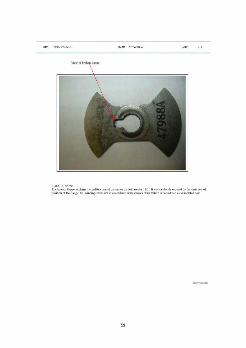
After further dismantling of the motor (P/N S4090, S/N 815D), the flange
was found free on the shaft(item 220 of Figure 1.8-1). The stop pin of the
flange was broken. Figure 1.8-1 and 1.8-2 illustrate the differences.

18 18
Figure 1.8-1 Normal flange
Figure 1.8-2 Damaged flange
The test report concluded that the broken pin on the flange explained the
malfunction of the motor on both modes 1 & 2. It was randomly ordered
by the variation of position of the flange.

19 19
1.9 Additional Information
1.9.1 Summary of Interview with Flight Crew
1.9.1.1 Flight crew
At 02:17(UTC), about an hour and half after take off, the aircraft was
cruising at way point, 30NM south “SALMI” at an altitude of 32,000 feet,
and a speed of 0.77M.
At that moment, "CAB PRESS REG 2 FAULT" message suddenly
appeared on ECAM, accompanying chime signals. And the flight crew
confirmed synoptic displayed automatically, which indicated cabin vertical
speed +1,000 feet per minute, showing cabin pressure altitude continually
increasing passed 9,000 feet.
In accordance with the pertaining procedure, the Captain (PF) instructed
the First Officer (PM) to carry out "ECAM Action," and the First Officer
switched off SYS 2, following the Captain's instruction.
As soon as SYS 2 was switched off, "CAB PRESS REG 1 FAULT"
message appeared on ECAM, and upon verifying synoptic, it was shown
that cabin vertical speed was increasing from +2,000 to +3,000 feet per
minute, with cabin pressure altitude passing over 10,000 feet, and CRC
(continuous repeated chime) warnings were activated.
The Captain instructed the First Officer to continually carry out "ECAM
Action," and accordingly the First Officer switched off SYS 1.
When SYS 1 was switched off, an ECAM Message to manually control
cabin pressure was displayed, however, when the flight crew noticed
cabin pressure altitude was passing over 12,000 feet, they decided to
execute an emergency descent rather than the manual control.

20 20
The flight crew remembered the circumstance and the actions taken as
follows:
Oxygen Masks – On
Crew Communication – Established
Emergency Descent - Executed.
The flight crew obtained a permission from the Taipei Air Control to
execute an emergency descent, maintaining en-route Transponder code
7700 was set due to the sudden cabin decompression to the extent of
suspecting of a structural damage (e.g.: door opened, etc) to the aircraft
at first, the flight crew maintained the descending speed at 280 knots, and
upon verification of no structural damage, they increased the speed to
315 knots. The items conducted by the flight crew during descent were as
following:
The flight crew used speed brake in air.
The flight crew confirmed P.A broadcasting automatically in
English and Korean.
The flight crew confirmed cabin oxygen masks dropped
automatically from overhead panels.
The flight crew carried out checklist items following memory
items.
The cabin crew called, asking whether to don on oxygen
masks in cabin, and the flight crew instructed to do so, as it
was a real decompression situation.
The flight crew confirmed cabin pressure altitude at 10,000
feet, taking off oxygen masks, and the Captain made a P.A.
and the Captain instructed to check the cabin situation.

21 21
Upon confirmation that there was no problem with continuing the flight at
an altitude of 10,000 feet to the destination with the remaining fuel (fuel
remained after completion of the flight: 13,200 lbs), the flight was
continued at an altitude of 10,000 feet and a speed of 315 knots (VMO 335
knots).
When SYS 1 and 2 switches, which had been turned off, were on again
for the confirmation of operation, cabin altimeter indicated normally at
about 1,200 feet, and the landing was made with the systems on. The
cockpit voice recorder C/B (Circuit Breaker) was not pulled out after
landing.
Open/close status of outflow valves were not confirmed in the air, while it
was shown after landing that forward valve was 1/4 open, with aft valve
3/4 open, and it was told by the Taipei ground engineer that according to
the function check result, forward valve was stuck open.
About 6 hours after landing, FWD outflow valve was replaced, and the
aircraft returned to Incheon International Airport as ferry flight

22 22
1.9.2 Summary of Operation Manuals
1.9.2.1 Flight Operations Manual

23 23

24 24

25 25
1.9.2.2 Flight Crew Operating Manual The related contents of Flight Crew Operating manual (FCOM)
are summary as following:

26 26

27 27

28 28

29 29
30 30
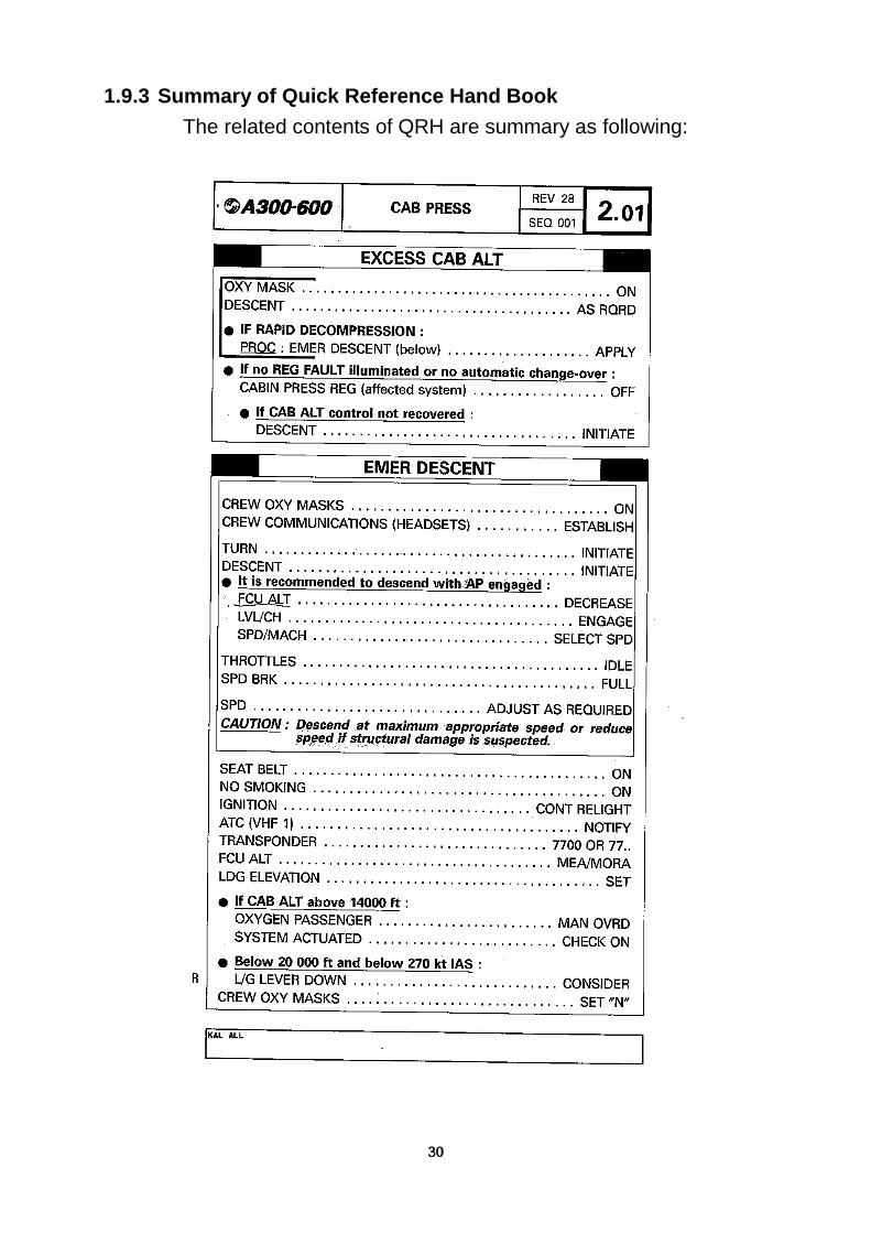
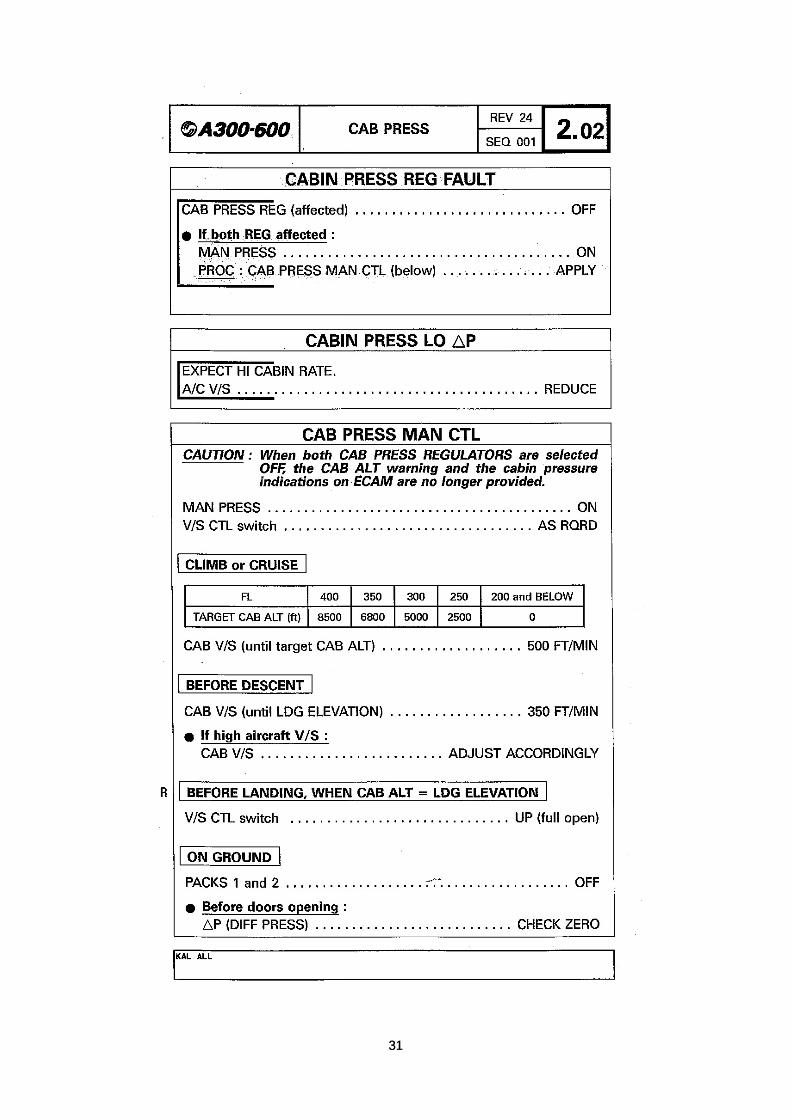
1.9.3 Summary of Quick Reference Hand Book The related contents of QRH are summary as following:
31 31

32 32
This Page Intentionally Left Blank

33 33
2 Analysis
2.1 General
The KE691 flight crew members were properly certificated and qualified
in accordance with the applicable Korean Civil Aviation Regulations.
The flight crew’s duty and rest periods were normal within the 72 hours
prior to the occurrence. There was no evidence indicating the crew had
any physical or psychological problems, nor any use of alcohol or drugs.
The aircraft was operated within allowable weight and balance limitations.
Based on the meteorological information contained in Section 1.5, there
was no adverse weather condition at the time of the occurrence.
2.2 Related factors
Based on the factual data collected during the investigation, the cabin
pressure loss occurred at about FL 320 and the flight crew conducted an
emergency descent. The cabin pressure loss resulted in the passenger
oxygen masks dropped automatically, however there was no crew and
passenger on board sustained injury. The related factors include cabin
pressure control and the flight crew disposition procedures are presented
as follows.
2.2.1 Cabin pressure control
The function of the cabin pressure system is dependent on
pre-programmed cabin altitude, aircraft altitude and pre-selected landing
altitude. The system is designed to ensure that during normal operation,
the cabin altitude will not exceed 8,000 ft within the aircraft’s maximum
cruising altitude. Maintaining a constant cabin altitude is a balance
between the entry of conditioned air from packs and the cabin air
evacuation to the ambient via out flow valves. If any out flow valve failed

34 34
to operate properly during flight, the cabin altitude would not be
maintained at the desired level.
The cabin pressure control system is composed of two independent
automatic control systems and a manual control system. The aircraft
maintenance manual (AMM) shows that there are two outflow valves
(FWD and AFT) which are operated by three electric motors and
controlled independently by one of the two automatic systems or the
manual system.
In accordance with the inspection of the failed FWD outflow valve, it
showed that a flange in the reduction gearbox which drived the FWD
outflow valve was broken (Ref. Fig1.4-3 and 1.4-4). That damaged flange
resulted in the malfunction of both auto modes input to drive the FWD
outflow valve.
The maintenance records of the system were reviewed and no anomalies
had been found. It was possible that the flange in the reduction gearbox
probably was broken accidentally during cruise. The AMM and FCOM
indicate that in this case even both of the auto modes failed to control the
outflow valves; the manual mode still could properly control the outflow
valves. The test result of that failed FWD outflow valve from LIEBHERR
AEROSPACE confirmed that both of the auto modes were malfunctioned
due to that broken flange, however, the manual mode to control the FWD
outflow valve was still operated.
The test report has no further description and analysis about the causes
of that failed flange. It would be better, for the operator’s privilege, to
know the rationale of the flange failure if the LIEBHERR AEROSPACE
could conduct more detailed exploration on that specific item.
2.2.2 Flight crew disposition procedures

35 35
In accordance with related flight operation manuals, there are three
emergency procedures related to the “Loss of Cabin Pressure” in this
event, which are “CABIN PRESS REG FAULT”, “EXCESS CAB ALT” and
“EMER DESCENT” (Ref. 1.9.2).
The “CABIN PRESS REG FAULT” procedures define that the flight crew
shall turn off the affected regulator and apply the manual control if both of
the regulators failed. The “EXCESS CAB ALT” procedures define that
flight crew shall turn off the affected regulator and conduct descent if the
cabin pressure could not be recovered; The procedures also define the
flight crew shall conduct emergency descent if a rapid decompression
happened.
The flight crew interview records indicated: At the moment of the “CAB
PRESS REG 2 FAULT” message appeared on ECAM in this occurrence,
the CM2 switched off the system 2 by following the “CABIN PRESS REG
FAULT” procedure provided on the QRH, as soon as the “CAB PRESS
REG 1 FAULT” message appeared on ECAM, the CM2 switched off the
system 1 by following the QRH action, but the flight crew found that the
cabin altitude increased rapidly and decided to conduct the emergency
descent procedure and neglected to complete the rest of the “CABIN
PRESS REG FAULT” procedures of using manual mode to control the
cabin pressure.
The flight crew dealt with this malfunction by following part of the QRH. In
accordance with the test results of the FWD outflow valve assembly, the
function of the manual mode of the system is normal. The emergency
descent took about 5 minutes from FL 320 to 10,000 ft, if the flight crew
continuously completed the rest of the “CABIN PRESS REG FAULT”
procedure, which was applied the manual mode to control the cabin
pressure simultaneously with the “EMERGENCY DESCENT” procedure,

36 36
the cabin pressure probably could be recovered before the aircraft
reaching the altitude of 10,000 ft.
If there were an integrated procedure to remind the flight crew to
continuously complete the “CABIN PRESS REG FAULT” procedures and
the “EMERGENCY DESCENT” procedures, the cabin altitude might be
controlled before the aircraft reaching the altitude of 10,000 ft..
2.3 Others
2.3.1 Emergency descent procedure
The “EMER DESCENT” procedure in A300-600 FCOM states that the
decent is initiated in a turn maneuver after the flight crew put on the
oxygen masks and established the communications. The maximum bank
angle is limited to 30°(Ref. 1.9.2.2). The rationale for the flight crew to
initiate the turning is trying to deviate the aircraft from the route to avoid
interfering with other traffic; it also could increase the descent rate to
arrive a safer altitude quicker and to diminish the negative G force during
the descent push down maneuver for prevent the passenger from being
injury.
The DFDR data shows that the aircraft initiated descent from FL320 at
02:17 UTC and leveled off at 10,000 ft at 02:22 UTC. It took about 5
minutes for the decent. The average decent rate was over 6,000 FPM.
During this period, the aircraft constantly kept the heading at around 220
without turning. It revealed that the flight crew did not follow the standard
procedure to conduct the emergency descent.

37 37
3 Conclusions
The Aviation Safety Council presents the findings derived from the factual
information gathered during the investigation of the KE0691 occurrence.
The findings are categorized as follows:
The findings related to the probable causes
The findings identify elements that have been shown to have operated in
the occurrence, or almost certainly to have operated in the occurrence.
These findings are associated with unsafe acts, unsafe conditions, or
safety deficiencies that are associated with safety significant events that
played a major role in the circumstances leading to the occurrence.
The findings related to risk
The findings identify elements of risk that have the potential to degrade
aviation safety. Some of the findings in this category identify unsafe acts,
unsafe conditions, and safety deficiencies that made this occurrence
more likely; however, they can not be clearly shown to have operated in
the occurrence. They also identify risks that increase the possibility of
property damage and personnel injury and death. Further, some of the
findings in this category identify risks that are unrelated to the occurrence,
but nonetheless were safety deficiencies that may warrant future safety
actions.
Other findings
Other findings identify elements that have the potential to enhance
aviation safety, resolve an issue of controversy, or clarify an issue of
unresolved ambiguity. Some of these findings are of general interest and
are not necessarily analytical, but they are often included in ICAO format

38 38
occurrence reports for informational, safety awareness, education, and
improvement purposes.
3.1 The findings related to the probable causes
1. A broken flange in the automatic mode motor drive component
caused the FWD outflow valve failed and the subsequent failure
of both auto modes in driving the FWD outflow valve. The failed
valve in both auto modes caused the cabin pressure loss. (2.2.1)
2. The flight crew did not apply the manual mode to control the
cabin pressure. (2.2.2)
3. There is no integrated procedures defined when both of cabin
pressure regulators failed and rapid decompression happened,
whether the flight crew shall continuously complete the “CABIN
PRESS REG FAULT” procedure or direct to the “EMERGENCY
DESCENT” procedure. (2.2.2)
3.2 The findings related to risk
1. The flight crew did not follow the standard procedures to initiate a
turn when conducted the “EMER DESCENT” procedures. (2.3)
3.3 Other findings
1. The flight crew members were properly certified and qualified in
accordance with the applicable Korean Civil Aviation Regulations.
(2.1)
2. There was no evidence indicating the crew had any physical or
psychological problems, nor any use of alcohol or drugs. (2.1)
3. The aircraft was operated within allowable weight and balance
limitations. (2.1)
4. There were no adverse weather conditions at the time of the
occurrence. (2.1)

39 39
5. The LIEBHERR AEROSPACE did not conduct more detailed
exploration on that specific damaged flange of the motor drive
component. (2.2.1)

40 40
This Page Intentionally Left Blank

41 41
4 Safety recommendations
4.1 Safety recommendations
To Korean Air
1. Ensure the flight crew to follow the specific emergency
procedures and enhance the operating proficiency.
(ASC-ASR-07-10-001)
2. Review and integrate the related emergency procedures to the
loss of cabin pressure. (ASC-ASR-07-10-002)
To Korean Ministry of Construction & Transportation
1. Monitor and survey the safety recommendation #1 and #2 to
Korean Air. (ASC-ASR-07-xx-003)
To LIEBHERR-AEROSPACE/France
1. Conduct more detailed exploration on the damaged flange of the
motor drive component(ASC-ASR-07-10-004)

42 42
This Page Intentionally Left Blank

43 43
Appendix1 DFDR tabular data and plots
Appendix 1a KE691 DFDR recorded parameters List
Appendix 1b KE691 relevant DFDR parameters plot2

44 44
(1a) KE691 DFDR recorded parameters List
Korean Air (A300-600, HL7297) FDR Parameters No. Parameters No. Parameters 1 ACID DOC A/C TAILNO 2 AFTCG AFT CG WARN 3 AILL AILRON LH +=RWD 4 AILR AILRON RH +=RWD 5 ALT PRESS ALT 6 AOA ANG OFATTACK (IND) 7 AP1CM A/P CMD #1 8 AP1CW A/P CWS #1 9 AP2CM A/P CMD #2 10 AP2CW A/P CWS #2 11 APUBV APU BLDVLVNOOPEN 12 BV1 BLEED VALVE ENG #1 13 BV2 BLEED VALVE ENG #2 14 CAL DFDAU CAL 15 CAS COMP AIRSPD 16 CG CENTRE OF GRAVTY 17 DAY DATE: DAY 18 DBASE DATA BASE UPDATE 19 DBASEC DATA BASE CYCLE 20 DBITE DFDAU BITE 21 EGT1 EGT ENG 1 22 EGT2 EGT ENG 2 23 ELEV ELEV POSN +=TED 24 EPR1 EPR ACTUALENG 1 25 EPR2 EPR ACTUALENG 2 26 EVENT EVENT BUTTON 27 FF1 FUEL FLOW ENG 1 28 FF2 FUEL FLOW ENG 2 29 FLAP FLAP POS 30 FLAPF FLAPS FAULT ASSYM 31 FLEET DOC FLEET ID 32 FLT DOC FLIGHTNUMBER 33 GSD1 GLIDE SLOPE +=FDN 34 HDGM MAG HEADNG 35 HF1 HF 1 KEYED
61 PACK1 PACK MANUALSEL #1 62 PACK2 PACK MANUALSEL #2 63 PITCH PITCH ANGLE +=N/UP 64 PROG DFDAU PROG IDENT 65 PTWS PITCH TRIM WHEEL 66 RALT RADIO HEIGHT 67 ROLL ROLL ANGLE +=RWD 68 RUDD RUDDERPOSN +=N/RT 69 SLAT SLAT POS 70 SLATF SLATS FAULT ASSYM 71 SPF14 SPOILR#1+#4 FAULT 72 SPF32 SPOILR#3+#2 FAULT 73 SPF5 SPOILR #5 FAULT 74 SPF6 SPOILR #6 FAULT 75 SPF7 SPOILR #7 FAULT 76 SRL1 SPOILR LH #1 77 SRL2 SPOILR LH #2 78 SRL3 SPOILR LH #3 79 SRL4 SPOILR LH #4 80 SRL5 SPOILR LH #5 81 SRL6 SPOILR LH #6 82 SRL7 SPOILR LH #7 83 SRR1 SPOILR RH #1 84 SRR2 SPOILR RH #2 85 SRR3 SPOILR RH #3 86 SRR4 SPOILR RH #4 87 SRR5 SPOILR RH #5 88 SRR6 SPOILR RH #6 89 SRR7 SPOILR RH #7 90 STAB STAB POS 91 STV1 START VALVE ENG #1 92 STV2 START VALVE ENG #2 93 SUP SUPER FRAME 94 SYNC SYNCH WORD 95 TAT TOTAL AIR TEMP

45 45
36 HF2 HF 2 KEYED 37 IAV1 INLET AI VLVENG #1 38 IAV2 INLET AI VLVENG #2 39 IM INNERMARKER 40 K_PHA_03 ROLLINPOWER 41 LAND1 A/P 1LAND TRACK 42 LAND2 A/P 2LAND TRACK 43 LATG LAT ACCEL 44 LGDLL LDG LH DOWN LOCKED 45 LGDLN LDG NS DOWN LOCKED 46 LGDLR LDG RH DOWN LOCKED 47 LGSQL LDG SQUAT SW LH 48 LGSQN LDG SQUAT SW NOS 49 LGSQR LDG SQUAT SW RH 50 LOC1 LOC DEVN 1 +=RT 51 LONG LONG ACCEL 52 MACH MACH NUMBER 53 MAIAS MAX ALLOW AIRSPD 54 MM MIDDLEMARKER 55 MON DATE: MONTH 56 N21 N2 ENG 1 57 N22 N2 ENG 2 58 OM OUTERMARKER 59 OQ1 OIL QTY ENG #1 60 OQ2 OIL QTY ENG #2
96 TRA1 THROTLRESLVRANG #1 97 TRA2 THROTLRESLVRANG #2 98 TRP1 T/R IN POSENG #1 99 TRP2 T/R IN POSENG 2 100 TRU1 T/R UNLOCKENG #1 101 TRU2 T/R UNLOCKENG #2 102 TYPE DOC A/C TYPE 103 UTC UNIVER TIME CLOCK 104 VHF1 VHF 1 KEYED 105 VHF2 VHF 2 KEYED 106 VHF3 VHF 3 KEYED 107 VIBF1 EVM FAN ENG #1 108 VIBF2 EVM FAN ENG #2 109 VIBT1 EVM TURBINENG #1 110 VIBT2 EVM TURBINENG #2 111 VMO VMO/ MMO OVRSPD 112 VRTG NORMALACCEL 113 WAIAL WING ANTICEALT L 114 WAIAR WING ANTICEALT R 115 WAINL WING ANTICENORM L 116 WAINR WING ANTICENORM R 117 XFV X-FEEDVALVE

46 46
(1b) KE691 relevant DFDR parameters plot
Fig. 1 KE691 relevant DFDR parameters plot (3,3000ft ~ landing roll)
Fig. 2 KE691 relevant DFDR parameters plot (4,000ft ~ landing roll)
47 47
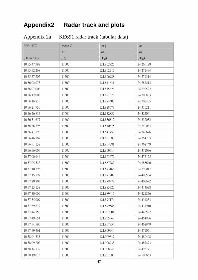
Appendix2 Radar track and plots
Appendix 2a KE691 radar track (tabular data)
FDR UTC Mode-C Long Lat
Alt Pos. Pos.
(Hh:mm:ss) (Ft) (Deg) (Deg)
10:55:47.398 11500 121.802725 24.265129
10:55:52.268 11500 121.802217 24.271434
10:55:57.202 11500 121.806988 24.279314
10:56:02.073 11500 121.811641 24.287213
10:56:07.008 11500 121.815626 24.292522
10:56:12.008 11500 121.821376 24.300833
10:56:16.815 11500 121.824407 24.308405
10:56:21.750 11500 121.828679 24.316211
10:56:26.815 11600 121.832832 24.324041
10:56:31.657 11600 121.836812 24.332032
10:56:36.396 11600 121.840675 24.340034
10:56:41.396 11600 121.847758 24.346676
10:56:46.267 11500 121.851380 24.354703
10:56:51.138 11500 121.854881 24.362749
10:56:56.009 11500 121.859514 24.371076
10:57:00.944 11500 121.863672 24.377125
10:57:05.528 11500 121.867982 24.385640
10:57:10.396 11500 121.873166 24.392017
10:57:15.397 11500 121.877207 24.400564
10:57:20.203 11600 121.879979 24.408672
10:57:25.138 11500 121.883722 24.414628
10:57:30.009 11500 121.889416 24.421856
10:57:35.009 11500 121.895174 24.431253
10:57:39.879 11500 121.899586 24.437910
10:57:44.750 11500 121.902804 24.446522
10:57:49.654 11500 121.905963 24.454986
10:57:54.590 11500 121.907954 24.462949
10:57:59.461 11500 121.909744 24.471051
10:58:04.333 11600 121.909347 24.480408
10:58:09.202 11600 121.908935 24.487473
10:58:14.139 11600 121.908348 24.496771
10:58:19.073 11600 121.907880 24.503653

48 48
10:58:23.944 11600 121.906154 24.512403
10:58:28.879 11500 121.905283 24.521609
10:58:33.815 11600 121.904591 24.528442
10:58:38.525 11600 121.901716 24.536622
10:58:43.510 11600 121.898788 24.544781
10:58:48.332 11600 121.895809 24.552919
10:58:53.267 11500 121.893648 24.561502
10:58:58.141 11500 121.889704 24.569118
10:59:03.009 11600 121.886561 24.577204
10:59:07.879 11600 121.884541 24.583548
10:59:12.944 11600 121.879687 24.590658
10:59:17.750 11600 121.876432 24.598677
10:59:22.750 11500 121.872350 24.606210
10:59:27.750 11500 121.869410 24.612043
10:59:32.750 11500 121.865272 24.619567
10:59:37.526 11500 121.861109 24.627077
10:59:42.461 11500 121.856921 24.634576
10:59:47.332 11500 121.853995 24.640227
10:59:52.209 11600 121.849751 24.647717
10:59:57.203 11600 121.844788 24.654769
11:00:02.073 11600 121.841207 24.662631
11:00:06.944 11600 121.838198 24.668241
11:00:11.880 11600 121.833198 24.675274
11:00:16.815 11600 121.828856 24.682695
11:00:21.719 11600 121.824488 24.690104
11:00:26.591 11600 121.821305 24.695816
11:00:31.526 11600 121.816268 24.702830
11:00:36.461 11600 121.811842 24.710209
11:00:41.332 11600 121.806792 24.717217
11:00:46.202 11600 121.802954 24.722543
11:00:51.138 11600 121.797325 24.729208
11:00:56.008 11600 121.791719 24.735888
11:01:00.944 11600 121.786135 24.742584
11:01:05.879 11600 121.781327 24.747142
11:01:10.721 11600 121.775259 24.753561
11:01:15.655 11600 121.768709 24.759706
11:01:20.525 11600 121.762741 24.766197
11:01:25.527 11600 121.758090 24.770870
11:01:30.332 11600 121.751709 24.777139

49 49
11:01:35.203 11600 121.745395 24.783456
11:01:40.138 11600 121.740296 24.788099
11:01:45.137 11600 121.733639 24.794250
11:01:49.944 11600 121.727072 24.800468
11:01:54.944 11600 121.721707 24.805006
11:01:59.750 11600 121.715308 24.811345
11:02:04.668 11500 121.709015 24.817722
11:02:09.591 11500 121.703967 24.822276
11:02:14.396 11400 121.697435 24.828563
11:02:19.396 11400 121.692138 24.833029
11:02:24.332 11300 121.685819 24.839462
11:02:29.202 11300 121.680234 24.844025
11:02:34.073 11200 121.673770 24.850437
11:02:39.008 11200 121.668410 24.855157
11:02:43.944 11100 121.663253 24.859767
11:02:48.815 11100 121.657479 24.864178
11:02:53.526 11000 121.651438 24.868667
11:02:58.400 11000 121.645476 24.870890
11:03:03.396 10900 121.638150 24.874841
11:03:08.750 10800 121.630787 24.876908
11:03:13.461 10800 121.624103 24.876886
11:03:18.397 10700 121.616832 24.876826
11:03:23.203 10600 121.609578 24.877149
11:03:28.073 10600 121.603297 24.875669
11:03:33.007 10500 121.596148 24.876402
11:03:38.073 10500 121.589183 24.875170
11:03:42.798 10400 121.582528 24.876198
11:03:47.815 10300 121.575900 24.875362
11:03:52.750 10300 121.569242 24.874750
11:03:57.750 10200 121.562448 24.876309
11:04:02.750 10100 121.556161 24.876042
11:04:07.750 10100 121.549204 24.875983
11:04:12.750 10000 121.542829 24.874044
11:04:17.750 9900 121.536140 24.874319
11:04:22.592 9900 121.529799 24.874790
11:04:27.396 9800 121.523138 24.875430
11:04:32.396 9700 121.516153 24.874257
11:04:37.204 9700 121.509818 24.875258
11:04:42.203 9600 121.503330 24.874184

50 50
11:04:47.009 9500 121.496410 24.873365
11:04:52.008 9400 121.489784 24.872824
11:04:56.815 9300 121.483423 24.872373
11:05:01.815 9200 121.476598 24.872035
11:05:06.657 9100 121.469703 24.871891
11:05:11.590 8900 121.463475 24.871825
11:05:16.815 8800 121.457210 24.871948
11:05:21.657 8700 121.450486 24.872220
11:05:26.658 8600 121.444390 24.872379
11:05:31.461 8500 121.436985 24.871202
11:05:36.397 8400 121.430765 24.871695
11:05:41.332 8300 121.424848 24.872167
11:05:46.202 8300 121.417870 24.871219
11:05:51.073 8200 121.411857 24.871994
11:05:56.008 8100 121.404940 24.871029
11:06:01.073 8000 121.399285 24.872036
11:06:05.815 7900 121.392114 24.871260
11:06:10.655 7900 121.387086 24.872110
11:06:15.592 7800 121.379891 24.871786
11:06:20.463 7700 121.373297 24.871151
11:06:25.461 7600 121.368161 24.872340
11:06:30.461 7500 121.361340 24.871850
11:06:35.267 7400 121.354696 24.871765
11:06:40.202 7300 121.349703 24.872906
11:06:45.073 7200 121.343186 24.872678
11:06:50.008 7100 121.336616 24.872586
11:06:55.202 6900 121.331546 24.874038
11:07:00.073 6800 121.325369 24.874004
11:07:05.012 6600 121.318869 24.873847
11:07:09.815 6400 121.312594 24.874043
11:07:14.879 6300 121.306023 24.874150
11:07:19.662 6200 121.300022 24.874254
11:07:24.647 6100 121.293708 24.874246
11:07:29.461 6000 121.287641 24.874564
11:07:34.332 5900 121.281259 24.874779
11:07:39.268 5800 121.275133 24.875314
11:07:44.202 5700 121.269022 24.875359
11:07:49.073 5500 121.262502 24.876501
11:07:54.073 5400 121.256337 24.876757

51 51
11:07:58.879 5300 121.251260 24.879726
11:08:03.879 5200 121.245896 24.883218
11:08:08.529 5200 121.240434 24.886734
11:08:13.464 5100 121.237023 24.891524
11:08:18.331 5000 121.233404 24.896808
11:08:23.333 4900 121.229893 24.902153
11:08:28.138 4800 121.228575 24.908617
11:08:33.138 4800 121.229466 24.915492
11:08:37.944 4700 121.228711 24.921444
11:08:42.815 4600 121.230305 24.927816
11:08:47.750 4500 121.234658 24.934160
11:08:52.750 4500 121.237036 24.938962
11:08:57.750 4400 121.241606 24.945097
11:09:02.750 0 121.246266 24.950592
11:09:07.525 4300 121.248934 24.955668
11:09:12.750 4300 121.253837 24.961468
11:09:17.750 4200 121.258839 24.967136
11:09:22.527 4200 121.261727 24.971439
11:09:27.526 4100 121.266758 24.977279
11:09:32.332 4000 121.269659 24.982248
11:09:37.269 4000 121.274755 24.987772
11:09:42.138 3900 121.277895 24.992963
11:09:47.138 3800 121.283077 24.998581
11:09:51.944 3800 121.286275 25.003484
11:09:56.944 3700 121.291761 25.009206
11:10:01.750 3700 121.294998 25.013816
11:10:06.750 3600 121.298583 25.018746
11:10:11.590 3600 121.304263 25.023942
11:10:16.526 3500 121.308038 25.027874
11:10:21.332 3500 121.314108 25.032767
11:10:26.333 3400 121.317860 25.036420
11:10:31.141 3400 121.324177 25.040653
11:10:36.138 3400 121.328120 25.045021
11:10:40.944 3400 121.332242 25.048636
11:10:45.879 3400 121.338775 25.052652
11:10:50.750 3400 121.342801 25.056549
11:10:55.815 3400 121.347279 25.060327
11:11:00.590 3400 121.351486 25.063654
11:11:05.597 3400 121.356106 25.067403

52 52
11:11:10.400 3400 121.360445 25.070711
11:11:15.590 3400 121.365216 25.073611
11:11:20.461 3400 121.369660 25.075865
11:11:25.332 3400 121.374479 25.077257
11:11:30.396 3400 121.378914 25.077862
11:11:35.202 3300 121.385872 25.077420
11:11:40.202 3200 121.390434 25.076839
11:11:45.008 3200 121.395011 25.076066
11:11:49.879 3100 121.399578 25.075543
11:11:54.815 3000 121.406354 25.075009
11:11:59.815 2900 121.411113 25.074736
11:12:04.599 2800 121.415504 25.074481
11:12:09.529 2700 121.420264 25.074234
11:12:14.396 2500 121.427028 25.073978
11:12:19.396 2400 121.431605 25.073762
11:12:24.202 2300 121.436184 25.073719
11:12:29.073 2200 121.440761 25.073522
11:12:33.398 2200 121.445358 25.073338
11:12:38.459 2100 121.449936 25.073167
11:12:43.277 2000 121.454515 25.073143
11:12:48.267 1900 121.459093 25.072991
11:12:53.269 1900 121.463691 25.072852
11:12:58.079 1800 121.466063 25.072609
11:13:02.944 1700 121.470458 25.072499
11:13:07.815 1700 121.475241 25.072402
11:13:12.884 1600 121.477429 25.072306
11:13:17.750 1600 121.482030 25.072135
11:13:22.750 1500 121.484401 25.072153
11:13:27.655 1500 121.486611 25.071990
11:13:32.532 1400 121.491194 25.071787
11:13:37.464 1400 121.493589 25.071661
11:13:42.269 1300 121.497987 25.071589
11:13:47.202 1300 121.500383 25.071496
11:13:52.138 1200 121.502759 25.071349
11:13:57.008 1200 121.507182 25.071285
11:14:01.944 1100 121.509560 25.071129
11:14:06.815 1100 121.514175 25.071043
11:14:11.815 1000 121.516373 25.070850
11:14:16.655 1000 121.518780 25.070752

53 53
11:14:21.525 900 121.523373 25.070755
11:14:26.461 0 121.525467 25.070544
11:14:31.460 800 121.528013 25.070372
11:14:36.267 0 121.532502 25.070407
11:14:41.138 700 121.534908 25.070183
11:14:46.073 600 121.537375 25.069929
11:14:51.075 600 121.542123 25.070149
11:14:55.882 0 121.543721 25.072490
54 54
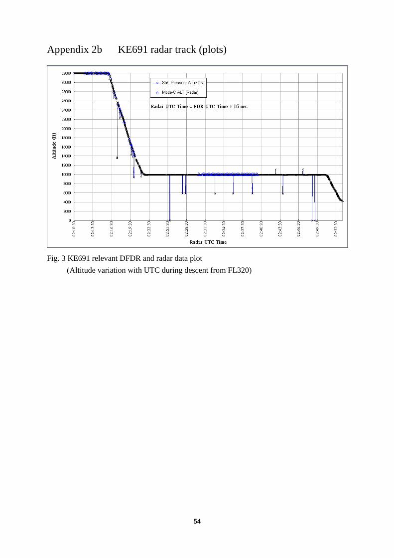
Appendix 2b KE691 radar track (plots)
Fig. 3 KE691 relevant DFDR and radar data plot
(Altitude variation with UTC during descent from FL320)

55 55
Fig. 4 Superposition of KE691 radar track and Taipei FIR chart
(UTC 1055~1114, descent from FL320, approach, and Landing)

56 56
This Page Intentionally Left Blank

57 57
Appendix3 Out Flow Valve Assembly Test Result

58 58
59 59

60 60

61 61